1
1
DVG-2032S
VOIP Gateway
User Manual
Version 1.0
Contents
1. Introduction....................................................................................................1
Product Overview .......................................................................................................................................... 1
Product Features........................................................................................................................................... 2
Hardware Description.................................................................................................................................... 3
2. Installation and Applications ........................................................................4
Network Interface .......................................................................................................................................... 4
Gateway Assigned with a Public IP Address...................................................................................... 4
Gateway in a NAT network ................................................................................................................. 5
Telephone Interface Description.................................................................................................................... 6
Example for DVG-2032S:................................................................................................................... 6
3. Setting the Gateway through IVR.................................................................7
IVR (Interactive Voice Response) ................................................................................................................. 7
IVR Functions Table: .......................................................................................................................... 9
IP Configuration Settings—Setting IP Configuration of WAN Port................................................... 11
1. Setting a Gateway with WEB Browser.......................................................14
Network Settings (WAN) ............................................................................................................................. 14
Network Settings (LAN)............................................................................................................................... 19
QoS Settings ............................................................................................................................................... 20
NAT/DDNS .................................................................................................................................................. 21
Telephony Settings ...................................................................................................................................... 23
SIP............................................................................................................................................................... 25
Calling Features .......................................................................................................................................... 29
Advanced Options ....................................................................................................................................... 31
Line Settings..................................................................................................................................... 32
Codec ............................................................................................................................................... 32
Fax Settings...................................................................................................................................... 33
Digit Map ..................................................................................................................................................... 35
Phone Book................................................................................................................................................. 35
Speed Dial ................................................................................................................................................... 35
Caller Filter .................................................................................................................................................. 36
ACL for Management .................................................................................................................................. 36
CDR Settings............................................................................................................................................... 37
Language .................................................................................................................................................... 37
CPT/Cadence Settings................................................................................................................................ 37
System Information ..................................................................................................................................... 38
RTP Packet Summary................................................................................................................................. 39
STUN Inquiry............................................................................................................................................... 39
Ping Test...................................................................................................................................................... 39
SNMP .......................................................................................................................................................... 40
NTP ............................................................................................................................................................. 40
Backup/Restore........................................................................................................................................... 40
Provision Settings........................................................................................................................................ 41
System Operations (Save Settings) ............................................................................................................ 41
Software Upgrade ....................................................................................................................................... 42
Logout ......................................................................................................................................................... 42
2. IP Sharing Functions...................................................................................43
2
3. Coding Principle ..........................................................................................46
Instruction.................................................................................................................................................... 46
Dialed Number Processing Flow................................................................................................................. 46
1
1. Introduction
Product Overview
The stand-alone VoIP Gateway carries both voice and facsimile over the IP network. It supports
SIP industry standard call control protocol to be compatible with free registration services or VoIP
service providers’ systems. It works in two different modes: UA (User Agent) or Server. As a
standard user agent, it is compatible to all well-known Soft Switches and SIP proxy servers.
While running the optional server software, the gateway can be configured to establish a private
VoIP network over the Internet without a 3rd party SIP Proxy Server.
The gateway can be seamlessly integrated to existing network by connecting to a phone set,
PBX, key telephone system, fax machine or PSTN line. With only a broadband connection such
as ADSL bridge/router, Cable Modem or leased line router, it allows you to gain access to voice
and fax services over IP in order to reduce the cost of international and long distance calls.
With the support of DDNS, it makes the gateway reachable by its domain name where the ISP
dynamically assigns the IP address. It helps users to host a web site or mail server in a PPPoE
or DHCP network. By enabling the CDR function & setting up a simple server, administrators are
allowed to log and view all call records such as call duration, time and date of calls and latency,
etc.
The gateway can be assigned with fixed IP address or by DHCP, PPPoE. It adopts the G.711,
G.726, G.729A or G.723.1 voice compression format to save the network bandwidth while
providing real-time and toll quality voice.
2
Product Features
● SIP (RFC 3261) compliant
● Optional server enables small businesses to build up private VoIP network (SIP model)
● QoS support guarantees voice bandwidth in a busy network
● Supports IP TOS (Type Of Service)
● T.30 (G III) / Real Time T.38 / Secured T.38 Fax Relay
● Feasible for Fixed IP address or dynamic IP address network ( PPPoE / DHCP client, support
DDNS)
● Configurable Hot Line feature
● Supports IP-to-PSTN / PSTN-to-IP applications
● NAT traversal - STUN and UPnP (optional)
● Pass through NAT
● Call Detailed Records (CDR)
● Web-based firmware upgrade
● Caller ID Delivery
● Easy Configuration by IVR and Web-based GUI
● Greeting message
● Echo Cancellation: G.168 compliant
● Voice Activity Detection (VAD) & Comfort Noise Generation (CNG)
● Dialing: DTMF, PULSE (optional)
● Signaling Protocol: Loop Start
● Adaptive Jitter Buffer and Programmable Gain Control
CALL features (optional)
● Call hold
● Call waiting
● Call forward
- Unconditional (follow me)
- Busy forward
- No answer forward
● Call transfer
3
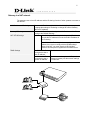
Hardware Description
Front Panel
Power Indicator: Green light indicates a normal power supply.
Run Indicator: Blinking green light indicates normal operation.
Alarm Indicator: When the system starts up, the red light will blink. It also indicates the
gateway’s abnormal operation.
P1 – P32 stands for Port 1 – Port 32: Connect to your analog telephone.
WAN stands for the WAN Port Indicator.
LAN stands for the LAN Port Indicator.
When starting up the system, the Alarm, Run, and Power indicators will light up.
After about 40 seconds, the Alarm indicator will go off, the Run indicator will blink
in green, and the Power indicator will stay green under normal operational
conditions. If the Alarm indicator continues to blink, it means the system is
currently communicating with ISP and has yet to obtain an IP address.
When the WAN is connected, the WAN indicator will light up in green and if data is
being transmitted over the Internet, the indicator blinks in green and orange.
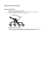
Rear Panel
NOTE: Do not connect Phone ports to each other. Also, do not connect any Phone ports
directly to a PSTN line or internal PBX. If any of these are done, your DVG-2032S may be
damaged.
Restore to factory default: (IP address, User’s. Name and Password)
(1) Pull off the power plug.
(2) Press reset (do not let go of the reset button).
(3) Plug the plug back into the socket (do not let go of the reset button).
(4) Let go of the reset button after 6 seconds. Factory settings will be restored.
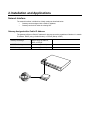
2. Installation and Applications
Network Interface
The network interface is divided into 3 basic modes as described below:
Gateway can be assigned with a Public IP Address
Gateway can be built under the existing NAT
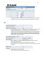
Gateway Assigned with a Public IP Address
The gateway will have a Public IP address for Internet connection regardless of whether it is a static
IP address, DHCP (using a Cable Modem), or PPPoE (Dialup / ADSL).
Gateway IP Settings
Need to set up as static IP,
DHCP, or PPPoE
NAT/STUN Settings
Unnecessary (Disabled)
DDNS Settings
Unnecessary (Disabled)
5
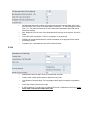
Gateway in a NAT network
The gateway uses a virtual IP address and the IP sharing function of other systems to connect to
the Internet.
LAN IP address of IP sharing
Please avoid IP address 192.168.0.1-192.168.8.254 (You may need
to change the settings of IP sharing or change SIP series Gateway
LAN Port IP address)
Gateway IP Settings
Set as static IP address, and assign the LAN IP address of the IP
sharing to the Default Gateway.
NAT /STUN Settings
Enable
If the WAN of the IP sharing device has static IP address,
then the NAT IP address is set as the Public IP address of
the IP sharing.
If the WAN of the IP sharing device uses a dynamic IP
address, then it has to comply with the DDNS settings.
When suing NAT, you must enter the URL (Uniform
Resource Locator) that is registered to the DDNS server.
DDNS Settings
The WAN of the IP
sharing device has a
static IP address.
Disabled
The WAN of the IP
sharing device has a
dynamic IP address.
Enabled: enter the registered URL (Uniform
Resource Locator) into the network settings
-> under NAT
Telephone Interface Description
Example for DVG-2032S:
DVG-2032S connecting directly to phone sets
After connecting telephone sets to P1-P32, users can make direct calls, (P1-P32 are FXS
interfaces). Each set acts as an independent extension line.
Integrating the DVG-2032S with PBX
P1-P32 is FXS interfaces, and some of them can be connected to telephone sets for direct calls.
Others can be connected to the PBX so other extension lines can make VoIP calls.
7
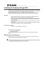
3. Setting the Gateway through IVR
VoIP transmits voice data (packet) via the Internet to achieve telecommunications. This means that
the telecommunication quality is closely related to the whole network environment. If any one of the
telecommunicating parties has insufficient bandwidth or frequent packet loss, the
telecommunication quality will be poor. Therefore, an excellent telecommunication can only be
created when Gateway is connected to the Internet and when network environment is stable.
Preparation
Install the Gateway according to instructions. Connect the power supply, telephone set,
telephone cable, and network cable properly as described in Chapter 2.
If a static IP is used, confirm the desired IP settings of the WAN Port (IP address, Subnet
Mask, and Default gateway). Please contact your local Internet Service Provider (ISP) if you
have any questions.
If using dialup ADSL (PPPoE) for network connection, confirm the dialup account number
and password.
If users wish to build Gateway under the NAT, Gateway WAN Port IP address and LAN Port
should not use the same range. This is to avoid phone failures.
Basic Settings of a Gateway
IP Settings— Connecting Gateway to the Internet.
Gateway provides two setting modes:
1. Telephone IVR Setting Mode
2. Browser Setting Mode
The IVR provides basic query and setting functions, while the browser provides a full setting
function.
IVR (Interactive Voice Response)
Gateway provides convenient IVR functions. Users only need to pick up a handset and enter the
function code for the query and setting without using a PC.
NOTE: After finishing the settings, make sure the new settings are saved. This is so that the
new settings will take effect after the system is restarted.
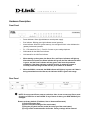
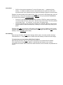
Instructions
FXS Port: Connected to telephones. To enter IVR mode, enter “ * * password #” after
hearing the dial tone. When you hear a second dial tone, the system is in IVR mode,
enter the function code. (Please refer to the Advanced Settings on page 35 for these codes)
Example: The factory default code is blank. Enter “**#”. You are now in IVR setting mode, enter the
desired code. E.g.: if the code is 1234, then enter “**1234#”. Or If your password is abc123 then
you access IVR by pressing ***414243010203#
FXO Port: to use IVR functions, dial the phone number of FXO Port using an external line.
You will hear the instruction “enter value”, and then enter a PIN number. The factory default
code is blank. Enter “**#” as above. You are now in IVR setting mode.
Once the first setting or query has been completed, you will hear a dial tone. Then use the
same procedure to make a second query or setting. To exit IVR mode, simply hang up the
phone.
Example: enter “**#” (You are now in IVR mode) enter 101 (to query IP address)
the system
responds with an IP address you can continue with more settings or queries: enter 111 (to set IP
address) enter 192*168*1*2 (IP number).
Save Settings
After entering IVR mode, dial 509 (Save Settings). Wait for about 3 seconds and after hearing a
confirmation tone “1”, hang up the phone. Please reboot the Gateway to enable the new settings.
To inquire about current Gateway’s WAN Port IP address
After entering IVR mode, dial 101. The system will repeat the current WAN Port IP address.
If the system does not repeat the IP address, it indicates that the Gateway is not currently
connected to the Internet. Please check if the cable connection, account number, and password are
correct.
9
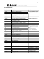
IVR Functions Table:
Function Code
Description
Example
111/101
WAN Port IP address Set/Query
112/102
WAN Port Subnet Mask Set/Query
113/103
WAN Port Default Gateway Set/Query
Use in conjunction with function
code 114, select 1 for a Static IP
function.
114/104
Current Network IP Access Set/Query (1: Static IP,
2.DHCP, 3.PPPoE)
115/105
DNS IP address Set/Query
116/106
Phone books manager IP address Set/Query
117/107
Set/Query whether or not to use Public Telephone
Book (0: Disable 1:Enable)
199/099
Set/Query whether or not this Gateway acts as the
phone books manager (0: Disable 1: Enable)
066
Querying the connection to Phone books manager
118
Restart
121
Setting PPPoE Account
122
Setting PPPoE Password
123
Setting NAT IP address
124
Uses NAT (0: Disable 1: Enable)
151/141
Register to Proxy Server Set/Query (0: Disable 1:
Enable)
152/142
Proxy Server IP address Set/Query
153/143
Proxy Server Port Set/Query
125
Set Proxy Server account
126
Set Proxy Server password
154/144
Uses STUN Set/Query (0: Disable 1: Enable)
155/145
STUN IP address Set/Query
156/146
STUN Port Set/Query
Must use 116/106, 117/107 in
conjunction with each other.
Use in conjunction with function
code 114, select 3 for a PPPoE
function
Must use 123 and 124 in
conjunction with each other.
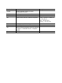
311/301
312/302
131/132
133
Saving greeting message
211/201
Set/Query International Prefix code
Prefix dialed before making an
international call e.g. 002 and 005.
212/202
Set/Query Country Code
Setting country code, e.g. 886
213/203
Set/Query Area Prefix Code (Long-Distance Prefix Prefix dialed before making a
Code)
long-distance call e.g. 0.
214/204
Set/Query Area Code
eg. “2” for Node B area.
Function Code
Description
215/205
Set/Query Gateway Telephone Number
(Representative Number)
216/206
Set/Query the extension number of Line 1.
Example
217/207
109
Restoring factory default IP address configuration
409
Restoring factory default settings
509
Save settings
900
Setting IVR and the language used on the Web GUI
(1: English, 2: Traditional Chinese, 3: Simplified
Chinese)
209
Soft Upgrade
A static IP address for WAN Port
IP:192.168.1.2
Mask:255.255.255.0
Gateway:192.168.1.254
11
IP Configuration Settings—Setting IP Configuration of WAN Port
Static IP Settings
NOTE: Complete static IP settings should include a static IP (Option 1 under114), IP address
(111), Subnet Mask (112), and Default Gateway (113). Please contact your local Internet
Service Provider (ISP) if you have any questions.
Function
Command
Select a Static IP
After entering IVR mode, dial 114.
After hearing “Enter value”, dial 1 (to select static IP)
IP address Settings
After entering IVR mode, dial 111. After hearing “Enter value”, enter your IP
address, followed by “#”.
Example: If the IP address is 192.168.1.200, dial 192*168*1*200#.
Subnet Mask Settings
After entering IVR mode, dial 112. After hearing “Enter value”, enter your
subnet mask, followed by “#”.
Example: If the mask value is 255.255.255.0, dial 255*255*255*0#.
Default Gateway Settings
After entering IVR mode, dial 113. After hearing “Enter value”, enter your
default gateway’s IP address, followed by “#”.
Example: If the Default Gateway is 192.168.1.254, dial 192*168*1*254#.
Save Settings and Restart
To save settings, dial 509 (Save Settings). The system will save the
settings. Please restart the system. Wait for about 40 seconds for the
system to restart, and then enter 101 to check if the IP address is retained.
If the IP address is not repeated, it indicates that Gateway has not been
properly connected, please check if the cable connection, account, or
password are correct.
Dynamic IP (DHCP) Settings
After entering IVR mode, dial 114.
After hearing “Enter value”, dial 2 (to select DHCP).
Saving settings –press 509 (Save Settings). Please restart the system. After the system is restarted,
press 101 to check if the IP address is retained.
If the system does not repeat the IP address, it indicates Gateway has not been properly
connected to the Internet. Please check the cable connection.
ADSL PPPoE Settings
NOTE: Complete PPPoE settings should include: Select PPPoE (Option 3 of 114), PPPoE
account (121) and PPPoE password (122).
Please contact your local Internet Service Provider (ISP) if you have any questions.
Select a PPPoE
After entering IVR mode, dial 114.
After hearing “Enter value”, dial 3 (to select PPPoE).
PPPoE Account Settings
After entering IVR mode, dial 121.
After hearing “Enter value”, enter the account number, followed by ”#”.
Example: If the account is “84943122 @ hinet.net”, please enter 08 04 09 04 03 01 02 02 71 48 49 54 45 60
72 54 45 60 #.
Please note that it is necessary to enter two digits for each character/number; for example,
enter “01” for “1” and “11” for “A”.
PPPoE Password Setting
After entering IVR mode, dial 122 after hearing “enter value” followed by “#”.
Example: If the password is “3ttixike”, please enter “03 60 60 49 64 49 51 45#”.
Save Settings and Restart
To save settings, dial 509 (Save Settings). The system will save the settings. Please restart the
system. Wait for about 40 seconds for the system to restart, and then enter 101 to check if the IP
address is retained. If the IP address is not repeated, it indicates that Gateway has not been
properly connected, please check if the cable connection, account, or password are correct.
13
PPPoE Character Conversion Table
Number
Input Key
Upper Case Input Key
Letter
Lower Case Input Key
Letter
Symbol
Input Key
0
00
A
11
a
41
@
71
1
01
B
12
b
42
•
72
2
02
C
13
c
43
!
73
3
03
D
14
d
44
"
74
4
04
E
15
e
45
$
75
5
05
F
16
f
46
%
76
6
06
G
17
g
47
&
77
7
07
H
18
h
48
'
78
8
08
I
19
i
49
(
79
9
09
J
20
j
50
)
80
K
21
k
51
+
81
L
22
l
52
,
82
M
23
m
53
-
83
N
24
n
54
/
84
O
25
o
55
:
85
P
26
p
56
;
86
Q
27
q
57
<
87
R
28
r
58
=
88
S
29
s
59
>
89
T
30
t
60
?
90
U
31
u
61
[
91
V
32
v
62
\
92
W
33
w
63
]
93
X
34
x
64
^
94
Y
35
y
65
_
95
Z
36
z
66
{
96
|
97
}
98
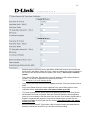
1. Setting a Gateway with WEB Browser
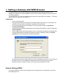
The gateway allows users to make settings using a web browser. After opening a browser, enter
Gateway’s IP address as the website address in order to enter the Web configuration screen as shown in
the following diagram.
You can also enter ”101” from the handset to inquire about the current WAN Port IP address. The factory
default LAN Port IP address is 192.168.8.254.
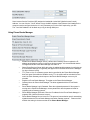
Instructions
Open an Internet browser.
Enter gateway’s WAN Port IP address in the website address area (If the PC is connected to the
LAN Port, enter the LAN Port IP address. The default is 192.168.8.254)
The following registration screen will appear (The factory default settings for Login ID and
Password are left blank).
Change the default settings of Administrator’s Name, Password and Web UI Login ID, Password in
Advanced Options.
After completing and confirming the settings, some of the settings will take effect immediately. But
network related settings would take effect after the gateway is restarted. Please go to System
Operation to save the settings before restarting the system.
The gateway doesn’t allow multiple people to configure the gateway at same time. If a user logs into
the system, other users from different IP addresses cannot login at the same time. Please
remember to logout or restart the system if not using the web configuration function.
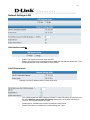
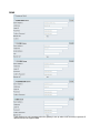
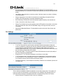
Network Settings (WAN)
The network settings are used to set the gateway’s communication ports, IP configurations, and Phone
Books Manager IP etc.
15
Listen Port UDP: It is not necessary to change the protocol of the communication port used
by the gateway.
RTP Starting Port UDP: The initial value of port number for transmitting voice data among
Gateway(s). Each line requires 2 ports (RTP/RTCP). It is not necessary to change these.
For example: If the starting port is 9000, then Line 1 is using 9000(RTP) and 9001(RTCP),
and Line 2 is using 9002 and 9003, and so forth.
IP Configuration (Setting WAN Port)
There are four methods of obtaining a WAN port IP address:
1. Static IP
2. DHCP, means a Dynamic IP (Cable Modem)
3. PPPoE (Dialup ADSL)
4. PPTP.
Using the DHCP and PPPoE for obtaining an IP address may vary. If not familiar with the network
connection, please contact your local ISP.
Setting Dynamic IP (DHCP)
Click “DHCP” to obtain a Dynamic IP address, then click the “Accept” button at the bottom of the screen.
Save the settings: Click System Operation to select “Save Settings”,
”Restart”, and then click the ”Accept” button. Wait for a while (about 40 seconds), and the system will
obtain the related IP value from the DHCP Server.
NOTE: After the system has obtained a new IP address, if using WAN Port to enter the Web Configuration
Screen, a new IP address has to be used. The same applies to the following two settings.
Setting Static IP
Select “Static IP” and enter the IP address, Subnet Mask and Default Gateway values. Then click the
“Accept” button at the bottom of the screen.
Save the settings, and then restart the system. Wait for about 40 seconds for the system to restart.
ADSL PPPoE Settings
Select “PPPoE” Enter the Account Number, Password and Reenter Password to confirm. Then click the
“Accept” button at the bottom.
Save the settings, and then restart the system. The system will take about 49 seconds to restart.
PPTP※
17
Select “PPTP” and enter the IP Address, Subnet mask, PPTP Server, PPTP ID and Password. Then click
the “Accept” button at the bottom.
BigPond (for Australia use only)
Click “BigPond Cable” Enter User Name and Password. Login Server is optional. Then click the “Accept”
button at the bottom.
(DNS) Settings
Domain Name Server (DNS): While a gateway is accessing another gateway or computer with a hostname,
it will look up the IP address from the DNS provided by ISP. The ISP whilst negotiating with PPPoE or
DHCP usually assigns the DNS information. In the case that the DNS is not assigned automatically or
WAN port is assigned with a static IP address, the DNS information must be assigned manually.
Auto : Gateway learns primary & secondary addresses from ISP’s DHCP server or PPPoE server.
Manual
: Enter the primary & secondary addresses manually. Please be sure the IP addresses are
correct otherwise the gateway will not be able to access hosts with its hostname.
Clone MAC
Some Internet Service Providers (ISP) assigns the bandwidth via the MAC (Media Access Control)
Address. You can click the " Clone" button to copy the MAC address of the Ethernet Card installed in the
computer used to configure the device. It is only necessary to fill in the field if required by your ISP.
The “Your MAC Address” will be blank as you log in through WAN port.
Using Phone Books Manager
Enable Phone Books Manager Server: It allows other Gateway users to register the IP
address and telephone number in this Phone books manager. It is recommended that the
unit appointed as the Phone Book Manager use static IP.
Share Phone Book to Clients: While this option is enabled and the gateway is performing as
a Phone Books Manager, this gateway will append its Phone Book entries to the Manager
for other clients to lookup.
TTL (Time to Live): If a Gateway system that is controlled by the Phone Books Manager
does not report back within the deadline set by TTL, the system will be excluded from the
user’s list. Each Gateway should report to the Phone Books Manager once every 30
seconds.
Register to Phone Books Manager: To register to the Phone Books Manager.
Gateway Name for Phone Book Manager: The alias registered with the Phone Books
Manager.
Phone Books Manager Login Password: Enter the registered password. If this system is
serving as the Phone Books Manager, the set password is also the password used for
registering other Gateway systems.
Phone Books Manager IP/Domain: Enter the IP address for the Phone Books Manager. It
supports URL (Uniform Resource Locator).
Phone Books Manager Server Listen Port: The protocol communication port for transmitting
signals between the Phone Books Manager and other Gateway systems. Please confirm
whether the setting is the same as that of the Phone Books Manager.
19
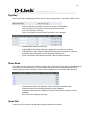
Network Settings (LAN)
LAN interface mode※
Router: The system serves as a router with NAT.
Bridge: The system serves as a bridge between WAN port and LAN port without NAT. (LAN
default gateway will still be accessible for configuration).
LAN IP/Subnet mask
Gateway LAN Port IP address and the subnet mask value.
Port of Web Access from WAN: Http port for WAN. To make this setting, the LAN Port must
be used. WAN Port cannot make this setting. Always use port 80 when connecting to
LAN port. 0 is to disable http port for WAN.
Enable Web UI: It disables any access from WAN and LAN if ticked.
Enable Telnet Service: It allows user to make settings from Telnet.
QoS Settings
WAN QoS
QoS (Quality of Service): Sets an external bandwidth to ensure sound quality during
transmission (When this function is enabled, the voice packet has the highest priority to
ensure telecommunication quality while less bandwidth is assigned for data transmission).
Some models of the gateway without this function can adjust the bandwidth automatically.
ToS/DiffServ (Type of Service/DSCP): The voice packet has the highest priority to ensure
telecommunication quality; the larger the value you set, the higher priority you will get.
21
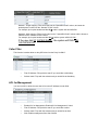
NAT/DDNS
NAT Traversal
If a Gateway is set up under an IP sharing setting, you can select either the NAT or STUN
protocol.
NAT Public IP: The IP address used by the gateway should be a virtual address. Further
more, users must set the Virtual Server Mapping in the NAT Server (A virtual server is
defined as a Service Port, and all requests to this port will be redirected to this specified the
server IP address).
The default port is listed below:
Listen Port (UDP): 5060
RTP Starting Port (UDP): 9000~9031 (Listen Port used for telephone communication).
Http Port (TCP): 80
NAT IP/Domain: Enter the NAT Server IP address (Real External IP address of NAT Server)
then fill in the URL (Uniform Resource Locator). If using DDNS, please refer to the next
setting item
Enable STUN Client: Using STUN protocol prevents problems with setting the IP sharing
function, but some NAT do not support this protocol.
STUN Server IP/Domain and Port: Enter the STUN server IP address and Listen Port
number. You can set 2 STUN server spread by semicolon.
Enable UPnP Control Point: To enable the gateway’s IP traffic to pass through a NAT
server. This function only works when the NAT server supports UPnP and has it enabled.
DDNS
These settings are only necessary when the gateway is set up under a NAT that uses a dynamic IP
address and do not support DDNS.
23
Choose a DDNS Server: The current system allows users to choose either DynDNS、TZO、3322.org、
PeanutHull or a private server. Please apply for a user account before choosing a service provider.
Server address: Sets up the IP address or URL (Uniform Resource Locator) of the DDNS
Server.
Hostname: The URL of the system (or NAT) – apply from a domain name registration
providers.
Login ID and Password: The ID and password are used to log into the DDNS server.
Behind NAT: Select only when the system is set up under NAT.
Note: If the Gateway is set up under NAT, then enter the hostname into the NAT IP/Domain that is the
same with Hostname of DDNS.
Example:
NAT
DDNS
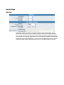
Telephony Settings
FXS Caller ID Generation: Select this option to enable the caller ID display function. When
enabled, the caller’s phone number will be displayed on your phone set when the call
comes through. FSK is preferred in some countries.
FSK Caller ID Type: Select FSK type. In most cases, Bellcore is preferred in North America
and ETSI in Europe.
Anonymous Caller ID (CLIR): When enabled, the caller’s phone set will not display your
number.
Note: If you register the gateway to a Proxy, you may be unable to make a call. This is due
to the fact that the gateway doesn’t send the number for authorization.
Enable: Enable a line; if some lines are not used, disable them (Pause Function) to avoid
unnecessary waiting when an incoming call is diverting to this line.
Hotline Functions
FXS port: When the user picks up the phone, the gateway automatically dials your assigned
hotline number. When in hotline mode, other lines cannot be used.
Hot Line No.: Enter the hot line number for an automatic dialing function.
Warm Line: When the warm line function is in use, user can dial a number. Otherwise the
system will divert incoming calls from an outside line to the Hot Line Number after a set wait
time.
FXS Group: Select group hunting when there is an incoming call, the gateway will
automatically assign an unassigned call according to Hunting Priority. If Line 2 does not
want to be set as an assigned line to receive any inbound calls, the function can be disabled.
Users can also use the Up or Down key to adjust hunting priority.
Enable FAX: Enable this line to detect if there is a FAX tone to transfer the Codec.
Ring Time Limit(10 - 600secs):The timeout to cancel a call when no one answers.
Enable End of Digit Tone:The gateway will play a “Beep-Beep” tone to notify the call is in
progress.
VoIP Calling Notification: The gateway will play a tone to notify the call is through VoIP.
Force Calling Thru PSTN code: Dial the code to get a PSTN line for dial out. For example: If
you would like dial “23456789” through PSTN and Force Calling Thru PSTN code is *33,
just dial “*33 23456789”
Early Media Treatment: If it is disabled, the system will send RTP immediately when the
connection with Proxy is set up. The default is enabled. If communicating with other
Gateway has problem, please disable this function.
25
Hunting/Ring: It is able to set FXS group hunting using simultaneous ring or sequential ring.
Sequential Ring Time: To set the ring time of each port, when sequential ring is chosen.
SIP
All Call through OutBound Proxy:An outbound proxy server handles SIP call signaling as a
standard SIP proxy server would. Furthermore, it receives and transmits phone
conversation traffic (media) in between two talking gateways. This option tells the gateway
to send and receive all SIP packets to the destined outbound proxy server rather than the
remote gateway. This helps VoIP calls to pass through any NAT protected network without
additional settings or techniques. Please make sure your VoIP service provider supports
outbound proxy services before enable it.
Session Expiration: It is to avoid the billing of abnormal dropping the call because of
Internet. The default is disabled.
Session Refresh Request: to send the packet of UPDATE or re-INVITE to
Session Refresher: It is the gateway’s role in Session Timer. UAS is an originator, and UAC
is a replier.
Enable P-Assert: It is for caller id protect.
Privacy Type: Privacy requested for Third-Party Asserted.
SIP Message Resend Timer Base: SIP packet will resend if response didn't arrive in the
base time set in this column. It will send again at "base time" * 2, and send again at "base
time" *2 *2. The max of resend time is 4 sec. Resend will stop/restart when total resend
20sec has reached.
Max. Response Time for Invite: If the destination does not reply in the set time, this call is
failed.
Invite URL need ‘user=phone’: There is ‘user=phone’ in invite packet.
Reliability of Provisional Responses: Provide information on the progress of the request
processing if ticked.
Compact Form: It decreases the size of SIP header if ticked.
E.164
International Call Prefix Digit: Enter the International call prefix.
Country Code: Users please select the desired country code.
Long Distance Call prefix Digit: The long-distance prefix digit for making a long-distance
call.
Area Code: Please enter the area code.
E.164 Numbering: To invite Proxy to follow the E.164 rule. It depends on the Proxy. If you
fail to make a call, please contact your ITSP.
27
Enable Support of SIP Proxy Server / Soft Switch: Enable the functions to inter-work with
Proxy Server / Soft Switch. When SIP Proxy 1 and 2 are enabled, the system will register to
SIP Proxy 2 after all lines are failed to register to SIP Proxy 1. SIP Proxy 2 is a backup
system.
Proxy Server IP/Domain: Enter the Proxy Server IP address or URL (Uniform Resource
Locator). You can set 3 redundant Proxy spread by semicolon.
EX: 61.123.231.1;12.34.56.78;proxy.sip.sip
Proxy Server Port: Enter the Proxy Server listen port number. (The factory default value is
5060)
Proxy Server Realm: Enter the correct registered Proxy Server Realm name to avoid
registration failure. If you fail to make a call, please contact your ITSP.
TTL: Enter the desired time interval at which the gateway will report to you Proxy Server.
SIP Domain/Use Domain to Register: Enter the correct SIP domain to avoid registration
failure (it is not necessary to set with some Proxy Servers). If you enable “Uses Domain to
Register” the gateway will register to Proxy with the domain name you filed. Else, the
gateway will register to a Proxy with the IP it resolves. If you fail to make a call, please
contact your ITSP.
Bind Proxy Interval for NAT: This function is able to keep the binding is existed when the
gateway is behind NAT and SIP Proxy is not able to keep the binding.
Initial Unregister: After rebooting, it is unregistered first and then do the general registry
process.
Enable Message Waiting Indication: The system will play a tone to remind users that there
are messages in SIP Server.
Proxy-Require: Some SIP Sever need SIP UA to add this header to it's sip message.
FXS Representative number registers to Proxy:
Assuming that your registered ID and password are individual, the settings should be as above.
FXS Representative Number: Register all FXS ports as a hunting group.
Register: Register to Proxy if ticked.
Invite with ID / Account: DVG-2032S can be invited to a VoIP trunk gateway w/o register to
a Proxy. Please contact your ITSP
NOTE: Please ensure that if Proxy Server allows one account for many ports using before using
representative number to register.
Each line registers to Proxy independently:
Invite with ID / Account: The gateway can be invited to a VoIP trunk gateway w/o register to
a Proxy. Please contact your ITSP
As there are various Proxy Server providers, our company has designed the gateway to be compatible with
them, and according to RFC standards. If any registration problem occurs, please consult your Proxy
Server provider.
29
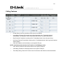
Calling Features
Do Not Disturb: It will only be able to call out when it is enabled.
Unconditional Forward: All incoming calls will be forwarded to the “Forwarding Number”
automatically. If it forwards to FXO, it only make FXO hook off, not make FXO dial out.
Busy Forward: Forward the incoming call to “Forwarding Number” when the port is busy.
No Answer Forward: Forward the incoming call to “Forwarding Number” after ring timeout expires
without answer.
Call Hold: Enable the call hold feature on the specific FXS port.
NOTE: Call Hold must be checked; Call Transfer or Call Waiting is active.
Call Transfer: Enable the call transfer feature on the specific FXS port.
Call Waiting: Enable the call waiting feature on the specific FXS port.
Three-Way Calling / Service ID: Feature code of conference call defined on Nortel Soft Switch.
Calling Feature Instructions:
Call Hold: Ongoing call will be put on hold after FLASH button pressed on the phone set. The
gateway will play a repeating music to the remote end.
Call Transfer: Ongoing call will be put on hold after FLASH button pressed on local phone set
(gateway plays a repeating music to the remote end). Meanwhile, local user can dial out to
another number after dial tone observed. After the handset is back on the hook, the call on hold
will then be transferred to the new call regardless of the status of the new call. If wrong number is
dialed for the new call, just press the FLASH button to get back the call on hold. In another case,
if the local user doesn’t hang up the phone after new call sets up, press FLASH button to switch
between the first call and the new call. Please be informed that PBX between phone sets and the
gateway must support FLASH features to make this function work correctly. If a phone set is
connecting directly to the FXS port of the gateway and not functioning to FLASH, please adjust
the settings in “Flash Detect Time” in category “Advanced Options”.
Example of a Three-Way calling:
1.
2.
3.
Or
4.
5.
6.
Alex dials to Bob, Bob answers that call.
Alex presses Flash and call to Coral (Bob is on hold), Coral answers that call.
Alex dials *61 then presses Flash, thus conference call is created.
Alex dials to Bob, Bob answers that call.
Coral dials to Alex (Call Waiting), Alex presses Flash to pick the second call and talk to
Coral.
Alex dials *61 then presses Flash, thus conference call is created.
31
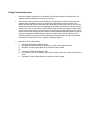
Advanced Options
There are two levels to enter Web. Administrator is able to change all settings. Web UI only
changes some settings.
NOTE: Enter new Login ID and password for two levels.
Web UI auto log out: When logging in a web page, if a user does not act within the effective
time range, the user will be disconnected from the web page to allow others to login.
Dial Wait Timeout: Use it to set the waiting time for the user’s first key pressing when dialing
a number. The user will hear a busy tone if he/she does not press the first key within the set
time frame.
Inter Digits Timeout: Set the waiting time between each key pressing. The inputted
numbers will be dialed after the timeout.
Minimum DTMF ON Length (Dial on)/ Minimum DTMF OFF Length (Dial off - between
tones): Used to set dial tone when a call is being diverted to another extension.
DTMF Detection Sensitivity: Used to adjust the sensitivity of the telephone keys.
FXS Impedance: Choose correct impedance in your country/area. ※
Enable Out-of-Band DTMF: To send DTMF keys (0~9, *, #,) follow the RFC2833 rules or via
SIP Info.
Enable Hook Flash Event: The gateway will deliver the flash signal to remote party via
RFC2833 or SIP Info.
Payload Type:Payload type of RFC2833.
Uses Second CPT for VoIP Call: This function is usually applied when the user selects VoIP
as the primary path for outgoing calls and PSTN as the backup. By enabling this function,
the gateway will generate a different set of tones to inform the user that VoIP is in service.
Should VoIP fails and fallback to PSTN, the user will hear PSTN tones instead of the
second set CPT. (for CPT related settings, please refer to Trunk Management -> CPT
Settings)
Line Settings
Listening Volume: Adjusts the hearing volume.
Speaking Volume: Adjusts the speaking volume.
Tone Volume: Adds a new option to make tone volume adjustable. This setting will be
applied to all tones generated by the gateway including Dial Tone, Busy Tone, and so on.
Flash Time: Used to adjust the detecting period of flash signal from the phone set
connected to the FXS port. For example, if pressing the HOLD key will disconnect a call,
increase the “Flash Detect Time” should fix this issue.
Enable Polarity Reversal: As the remote site answer this call or hook on the FXS port will
reverse the polarity.
Codec
Preferred Codec Type: Since different voice codec have different compression ratios, so
33
the sound quality and occupied bandwidths are also different. It is recommended to use the
default provided (G.723.1) because it occupies less bandwidth and will provide better sound
quality.
Jitter Buffer: Adjusts the jitter to receive a packet. If the jitter range is too wide, it will delay
voice transmission.
Silence Suppression: If one side of a connection is not speaking, the system will stop
sending voice data (package) to decrease bandwidth usage.
Echo Canceling: Prevents poor telecommunication quality caused by echo interference.
Codec: Choose the codec that you needs.
Packet Time: Defines how long the gateway sends a RTP packet-voice packet- to the other
side. The smaller the value, the more bandwidth usage. The larger the value, the more
voice delay.
Approximate Bandwidth Require: The bandwidth required varies with Codec format and
packet time.
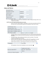
Fax Settings
T.38: The T.38 protocol is used for better and faster facsimile transmission. When this
function is enabled, the following fax and voice parameter settings will be disabled, so it is
recommended to enable this function to gain better fax quality. When this function is
enabled, please select UDP, TCP, or AUTO. If selecting TCP and some routers cannot use
the Fax function, please select UDP instead.
Enable High Quality: The system sends the same FAX frame twice to get a high quality of
the FAX. It requires more bandwidth.
Enable Secure T.38: This allows gateways to send faxes on both sides.
T.30: The system uses T.30 as the protocol for fax transmission. The parameter settings
are the same as for voice transmission. However, enabling the fax function will consume
more network resources and will affect transmission quality.
FAX Detect sensitivity:Used to adjust the sensitivity of detection as to whether a phone call
is a FAX or not.
This is used as a standard to determine whether or not to hang up the phone. The system will
hang up the phone automatically to avoid keeping the line engaged if the detected volume is
below the Silence Detection Threshold and the time exceeds the Drop Silent Call Timeout.
Silence Detection Threshold: Set the volume as a standard.
Drop Silent Call Timeout: Set the time to hang up the phone.
35
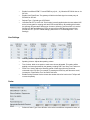
Digit Map
There are 50 sets of leading digit entries to choose voice routing interface – Auto select, PSTN or VoIP.
Default Call Route: The default call route can be Auto, VoIP and Deny.
Auto (VoIP first): The call route is VoIP first, and the next is Deny.
VoIP: The call route is VoIP only.
Deny: The call will be deny if the dial-out number is not in the table.
Enable: Enable detection of this entry.
Leading Digits: The leading digits for the gateway to scan while user is dialing.
Total Digit Count: Total number of digits that the gateway should accept. 0 is that the
gateway scans leading digits only and disregards total digit count.
Route: The interface calls should go through if above conditions satisfied.
Phone Book
This system can set up and store 100 phone numbers into a phone book and provides an IP address query
when calling to other gateway(s). If no Phone books manager is set within a gateway group, then all
Gateway systems have to set up phone data for each the gateway to communicate with each other.
Gateway Name: Enter other gateways’ code or an easy-to-remember name.
Gateway Number: Enter the desired number of other Gateways.
IP/Domain Name: Enter the IP address or URL (Uniform Resource Locator) of other
gateways.
Port: Enter other Gateways’ listen port.
Speed Dial
It can set up 100 numbers for speed dialing. Setting methods are as follows.
Method 1- Single mapping: Fill a short code into the “Speed Dial Code” column, and enter the
desired phone number into the “Number To Dial” column.
For example, pick up the handset and dial 55# and the system will dial 32568791.
Method 2- Multi mapping; Fill the prefix code into the ” Speed Dial Code” column and the format to
transfer into the “Number To Dial” column.
For example, pick up the handset and dial 301#, and the system will dial 521301.
If the user dial 00 1657987456321, the system will DIAL 856
1657987456321
Caller Filter
This function is used at allow or deny SIP Invite from the Proxy list ONLY.
Filter IP Address: Fill up with the start IP you would like to allow/deny.
Subnet mask: Fill up with the subnet mask you would like to allow/deny.
ACL for Management
You can use ACL to allow the user that is from some IP address to enter Web.
Enable ACL for Management: Enable ACL for Management if ticked.
Filter IP Address: Fill up with the start IP you would like to allow.
Subnet mask: Fill up with the subnet mask you would like to allow.
Web: Enable management from Web if ticked.
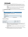
37
CDR Settings
The user can set up a CDR Server to record call details for every phone call.
The present CDR provides the call detail recording in a text file and if needed. it can be imported to prepare
for an analysis report.
Send record to CDR Server: Enables the call detail recording function.
CDR Server IP: Enter the IP address of the CDR server.
Port: Enter the listen port of the CDR server.
Language
The system provides English, Traditional Chinese, and Simplified Chinese to display text on Web pages.
Meanwhile, it will change the language for IVR (Interactive Voice Response).
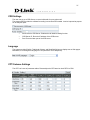
CPT/Cadence Settings
The CPT has 3 sets of parameter tables. Please adjust the CPT based on local PSTN or PBX.
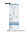
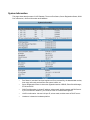
System Information
This page shows that the status of VoIP Gateway. There are Port Status, Server Registration Status, WAN
Port Information, LAN Port Information and Hardware.
Port Status: It includes if each port registers to Proxy successfully, the lasted dialed number,
how many calls each port had since the system is start, etc.
Server Registration Status: It shows the registration status of DDNS, Phone Book Manager,
STUN and UPnP.
WAN Port Information: It shows IP address, subnet mask, default gateway and DNS server.
If you use PPPoE to obtain IP, you can know if the IP is obtained through this.
LAN Port Information: It shows LAN port IP, subnet mask, and the status of DHCP server.
Hardware: It shows the hardware platform.
39
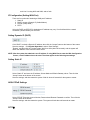
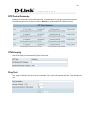
RTP Packet Summary
Displays the information of the last finished call. It contains peer IP, peer port, packets sent, packet
received and packet lost. Press the button of Refresh to get the latest RTP Packet Summary.
STUN Inquiry
Use STUN Inquiry to know what NAT type of the router.
Ping Test
Use “ping” to identify if the remote peer is reachable. Fill in remote IP address and click “Test” will start the
test.
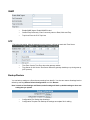
SNMP
Enable SNMP Agent: Enable SNMP if ticked.
Get/Set/Trap Community: Enter Community name to Read, Write and Trap.
Trap Host: Enter the IP of Trap Host.
NTP
This is the time setting. After the gateway is on the Internet, it will set its watch with Time Server.
Time Zone: Set the Time Zone where the gateway resides.
Time Server #1~#3: Set the Time Server where the gateway should sync up during start up.
(NTP protocol)
Backup/Restore
You can backup settings to a file and restore settings from that file. You also can restore all settings back to
default by selecting Restore Default Configurations and click Restore.
Note: It needs to Save Settings and Restart, and all settings will back up default settings or have new
setting that you upload.
Configuration File: Backup the all settings.
Configuration Template File: Backup the settings as template file for editing.
41
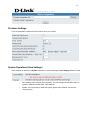
Provision Settings
Fill in the parameters needed of Provision Server from your provider.
System Operations (Save Settings)
Some settings are effective by Restart. Remember to save all settings by Save Settings before to restart.
Save Settings: Save settings after completing. The new settings will take effect after the
system is restarted. Please select “Save Settings”.
Restart: If it is necessary to restart the system, please select “Restart” and click the
“Accept” button.
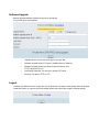
Software Upgrade
Gateway provides software upgrade function for a remote end.
Your provider gives all parameters.
Upgrade Server: Choose the server type of your provider.
Software Upgrade Server IP: Enter the software server IP address.
Software Upgrade Server Port: Enter the port that server uses.
TFTP is 69, and FTP is 21.
User Name/ Password: The account to access FTP server.
Directory: The path of TFTP or FTP.
Logout
Gateway only allows one user to login at a time, so whenever a change is made, please save the settings,
restart the system, or logout to avoid the situation where other users cannot login to change settings.
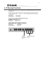
43
2. IP Sharing Functions
All Gateway series have a built-in IP sharing function. The settings and instructions at a PC end are
described below:
Current Intranet only supports static IP mode, and the settings at the PC end are as follow:
Available IP address Range : 192.168.8.1 – 192.168.8.253 (default address of Gateway is
192.168.8.254)
Subnet Mask
: 255.255.255.0
Default Gateway
: 192.168.8.254
The above values vary with different LAN Port Settings.
Assume Gateway’s LAN settings are,
IP address : 192.168.3.1
Subnet Mask
: 255.255.255.0
Then, the settings at PC end should be as follows:
Valid IP address range : 192.168.3.2 – 192.168.3.254
Subnet Mask
: 255.255.255.0
Default Gateway
: 192.168.3.1
WAN Port
Connected to
Internet
LAN Port connected to
Intranet
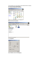
The IP settings on PC are as follows (using Windows 2000 for example)
Open Start->Settings->Control Panel
Open Network and Dial-up Connection
Open Local Area Connection
Click Properties
Select TCP/IP, and then click Properties.
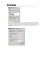
45
Select “Use the following IP Address ” and enter IP address, Subnet Mask, and Default Gateway.
Please note that an IP address in the same domain cannot be reused. Then, enter the DNS server
IP address (varies in different networks. consult your ISP’s service for information). Click the “OK”
button and after completing the settings, users can use both the VoIP and network services
concurrently.
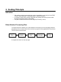
3. Coding Principle
Instruction
After a phone number is entered, dial # to call out immediately or, wait until the “Inter DTMF
Timeout” expires (defined in “Advanced Options”, default=4 seconds).
If the phone number fits the setting of Digit Map, the gateway dials out the phone number
through the assigned interface automatically.
The phone number should have at least 2 digits (not including * and #).
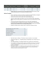
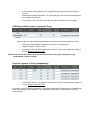
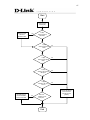
Dialed Number Processing Flow
To maintain maximum flexibility, the number dialed will be looked up from several tables defined in
the gateway. Once no match can be found, it will look up again from the registered SIP Proxy Server.
The look up flow is shown below:
Speed Dial
Table
Extension
Number
Local Phone
Book
A complete flow chart is on the next page.
Phone Book
Manager
SIP
Proxy
47
Start
Enter a phone
number (D#)
Dial the number
defined in
SpeedDial table
Yes
Is (D#)
defined in Speed
Dial table?
No
Is (D#)
defined in Extension
table?
Yes
No
Is (D#)
defined in Phonebook
table?
Yes
No
Is (D#)
defined in Phonebook
Manager?
Yes
No
Is (D#)
defined in SIP proxy
server?
Yes
No
Dial (D#) through
the first available
FXO port to PSTN
Yes
Does this
gateway has an
FXO port?
No
End
Dial out as defined
in the first match
case through the
gateway