1
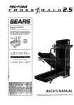
Model No. WLTL42570
_;eria[ No.
Serial
Number
Decal
QUESTIONS?
As a manufacturer, we are comrn_ed to providing complete
customer satisfaction. If you
have questions, or if there are
mLssJng or damaged parts, we
will guarantee complete s_tisfaction through direct assistance
from our factory.
TO AVOID UNNECESSARY
DELAYS, PLEASE CALL DIRECT TO
OUR TOLL-FREE CUSTOMER
HOT LINE. The trained technicians on our Customer Hot Line
will provide immediate assista_ce_ free of charge to you.
CUSTOMER
HOT LINE:
1-800-999-3756
Mon.-FrL,
6 a.m.-6
p.rn, MST
USER'S MANUAL
TABLE OF CONTENTS
IMPORTANT PRECAUTIONS
.................................................................
BEFORE YOU BEGIN .......................................................................
ASSEMBLY
...............................................................................
OPERATION AND ADJUSTMENT
.............................................................
HOW TO FOLD AND MOVE THE TREADMILL
MAINTENANCE
AND TROUBLE-SHOOTiNG
2
4
5
7
..................................................
...................................................
10
12
CONDITIONING
GUIDELINES
...............................................................
ORDERING REPLACEMENT
PARTS ..................................................
LIMITED WARRANTY
...............................................................
14
gsck Cover
Back Cover
Note: An EXPLODED DRAWING and a PART LIST are attached to the center of this manual
EXPLODED DRAWING and PART LIST for future reference,
iMPORTANT
Save the
PRECAUTIONS
extension
_e_d.
12, Keep the power _ord arid _he surge protector
6. Ke_p_hfldren
ur_derthe _ge of 12 and pets
avl_y f_t
at 811times.
the treadmill
away from heate_lsurfaces_
13. Neve? move the walldng
7. Tt_ treadmill _hould be used only by persons
weighing 250 pounds or less.
8,
Neveralfowntorethanonepersononthe
treadmill at a tlm_.
belt whil_
the power
is turned off, Do not operate the treadmil_ if
the. power cord or plt_J is damaged= or If the
treadmill is not working properly. (See
REFORE YOU BEGtN on pagr8 4 if the treadmill is not working properly.)
The deca! shown below has been placed on your treadmill.
If the decal IS miss'rig, or If d "s no! legible
please call our Customer s_rvice Department, toll-free, to order a |ree repla_em_t_t decat (.see ORDERING
REPLACEMENT
pARTS on the back cover of this manual). Apply the decal in t_e Iccatlon shown.
BEFORE YOU BEGIN
Thank you for select[ng the WESLO CADENC_
LX25
lreedmill, Tile CADENCE LX25 treadmill combines advanced technology witr_ innovative design to let you
enjoy an excellent form of cardiovascular exercise in
the convenience and privacy of your home. And when
you're not exercising, the unique CADENCE LX25 can
be folded up, requiring less than halt the floor spaca of
other treadmills.
For your benefit, read this manual carefully before
using the treadmill, Lfyou have additional questions,
please calf our Customer S_ice
Department toLl-tree
at 1-800-999-3758,
Monday through Friday, 6 a.m.
until 6 p.m. Mountain Time (excluding holidays). To
help us assist you, please note the product model
number and serial number betor_ calling. The model
number of the treadmill is WLTL42570. The sedal
number can be found on a decal attached to the treadmill (see the front cover of this manual for the location).
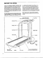
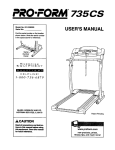
Before reading further, please review the drawing
below and familiarize yourself with the parts that are
labeled.
Water Bottle Holder
IWater Bcttfe is not
Towel
Rack
Accesso W Tray
Storage L
Mandmils
RtGHT SIDE
Waikin
Circuit
Breaker
Power
CoG
BACK
Incline Leg
Cushioned
for maximum
Walkit'_j Platform
ex_l'cise comfort
ASSEMBLY
.... two people Set the treadmlg In a cteared arsa and remove all packing maten_ is . Done
Assembly requires
dispose of the packing materials until assembly is completed. Refer to the drawings below to }denfify the parts
Used.in assembly: Assembly
phghp" ._=rewdr,ver _
requires the fo!lowing tools: The include_
and adjustable
wrench _
alien wtenchnch_ and your own
.
U©
Handrai_ Screw (32)-2
Handrail Washer (16)-2
L_.tch Screw (13)-2
Console pJate Screw (89)-8
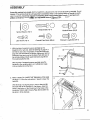
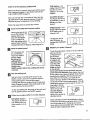
1. W_th the help of a second person, carefulfy Jay the
treadmill on its right side. (See the drawing _n page 4 to
identify the dghl side, if necessary.) Insert the Extension
Legs (41) into the treadmill as shown. Make sure that the
Extension Legs are turned so the Base Pads (36) are on
the indicated sides. Attach each Exlension Leg with an
Extension Leg Screw (34).
Extension Leg Screw (34)-2
41
With the help of B second person, carefully raise the
treadmill to the upright position se the ExtensTon Legs
(41) are resting flat on the floor.
2, Refer to HOW TO LOWER THE TREADMILL
FOR USE
on page 11. Foflow the irlstr_ctions in step 2 to lower the
treadmill.
i
•
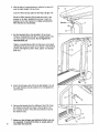
Wgh the help of a second person, insert a Henchalt (2)
into each side of the Oonsore (11) as shown. Align the
holes in the bottom of the Console with the holes in the
Handrails. Tighten eight Console Plate Screws (89) into
the bottom of the Console,
2
11
3. With the help of a second person, hold the Console (11 )
near the right Upright (14) as shown.
Insert the Wire Harness (26) into the Right Upright (14).
Route the Wire Harness (26) through the notch in the
bracket on the dght Handrail (2) as shown. Insert the
bracket into the right Upright (14). Make sure that the
Wire Harness is not pinched.
Bracket.
4. Set the Handrails (2) on the Uprights (14) as shown.
Thread a Handrail Bolt (15) with a Handrail Washer (16)
into each Upright and Handrail. Do not tighter= the
Hsndrail Bolts yet.
Tighten a Handrail Screw (32) into the lower end ol each
Handrail (2), Be sure to push on the heads of the Handrail
Screws while tightening them. Next. tighte_ the Handrail
Bolts (15).
5. Attach the Storage Latch (12) 1o the left Upright (14) with
two Latch Screws (13). Be careful not to overtighten the
Latch Screws.
6. Remove the backing from the Adhesive Clip (74). Press
the Adhesive Clip onto the base of the Uprights (14} in
the indicated location. Press the AIMn Wrench (73) into
the Adhesive Clip.
7.
B
Make sure that all parts
are tightened
the treadmill,
TO protect
mat under the treadmgl.
the floor
before
or carpet,
you use
place
a
4
_
12
OPERATION AND ADJUSTMENT
THE PERFORMANT
LUBE
TM
WALKING
BELT
Your treadmill features a walking belt coated with
PERFORMANT LUBE TM, a high-performance
lubricant.
Important:
Never apply silicone spray or other sub*
stances to the walking belt or the walking platform.
They wgl deteriorate the walking belt and cause excessive wear.
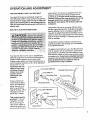
electric shock, This product is equipped with a cord
having an equipment-grounding
conductor and a
grounding plug. Plug the power cord into a surge
protector, and plug the surge protector into an appropriate outlet that is properly installed and
grounded in accordance with all Ioca! codes and
ordinances.
This product is for use on a nominal 120-volt cimuit,
and has a grounding plug that looks like the plug illustrated in drawing 1 berow. A temporary adapter that
looks like the adapter glustrated in drawing 2 may he
used to connect the surge protector to a 2-pole receptacle as shown in drawing 2 if a properly grounded outlet is not available.
HOW TO PLUG IN THE POWER CORD
The temporary adapter should be used only until a
propedy grounded outlet (drawing 1) can be insta!led
by a qualified electrician.
not fit the O_ et t'm_,e a proper Outlet _1
s tailed by a icJ_an_
q ua_lf,_d _lect r
.....
The green-colored rigid ear, lug, orthe like extending
from the adapter must be connected to a permanent
ground such as a properly grounded outlet box cover,
Whenever the adapter is used it must be held in place
by a metal screw, Some 2-pole receptacle outlet box
covers 8r_ Rot grounded. Contact a qualified electribian to determine if the outlet box cover is
Your treadmill, like any ether type of sophisticated
electronic equipment, can be seriously damaged fay
sudden voltage changes in your home's power,
Voltage surges, spikes, and noise interference can regrounded before using an adapter.
sult from weather conditions or from other appli_.nces
being turned on or off.
To decrease the possibigty of your tread/Grounded
Outlet Box
mill being damaged,
Treadmill Power Cord_
atways use a surge
protector (not in/Grounding
Pi.n
cluded) with your
Groundin
treadmgl.
_undlng
Surge prolectors are
sold at most hardware
stores and department
stores, Use onty a ULlisted surge p_ctector,
rated at 15 amps, with a
14-gauge cord Qf five
feet or tess in length.
_munded Outlet
2
Grounded
This product must be
grounded. If ft should
malfunction or break
down, grounding provides a path of least resistance for electric current to reduce the risk of
Plug
Grounding
Pin,_
Outlet Box
'Surge
MetJ
Protector
DIAGRAM
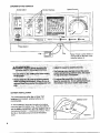
OF THE CONSOLE
Inct_eSu(ton
Speed Cont_l
Monitor Disp(ays
Key
BA'R'ERY
INSTALLATION
The co_oJe requires either two Dr three "AA"
batteries (not included); alkaline batte es a e
recommended.
To install batteries, first press the tab on the batte_
cover atld o_etl the balte_j cover. Press the batteries
intothebatterycompartment,
withthenegativeendsof
the
batteries
(m_rked
"-")
touching
the springs.
Press
the tab on the battery cover and cio_e the battery
cover.
Note: If there is a thin sheet _f
clear plastic on the face of the
_nsole, remove it.
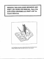
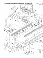
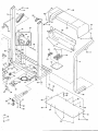
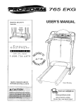
REMOVE THIS EXPLODED DRAWING AND
PART LIST FROM THE MANUAL. Save this
EXPLODED DRAWING and PART LIST for
future reference.
Note: Specifications are subject to change without notice. For information about
ordering replacement parts, sea the back cover of the User's Manual.
EXPLODED DRAWiNG--Model
No. WLTL42570
RO997B
87 86
39
63
32
22
67
75
74
51
72
i.
46
13
16
71
39
71
16
15
15
16
28
29
13
• 47
35
41
39"
37
54
/52
35
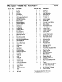
PART LIST--Model No, WLTL42570
Key No. Qty.
1
2
3
4
5
6
7
8
9
10
11"
12
13
14
15
16
17
18
1g*
20
21
22
23
24
25
26
27
28
29
30
31
32
33
34
35
36
37
38
39
4O
41
42
43
44
45
46
47
48
49
50
1
2
2
t
4
t
1
1
1
1
!
1
6
1
2
5
1
1
1
1
1
4
1
1
1
1
3
1
1
2
1
2
2
2
40
4
2
2
7
1
2
1
1
1
2
4
16
f
1
2
DescripUon
Key/Clip
Handrail
Cage Nut
Incline Motor
Rear Isolator Screw
Left Console Attachment
Speed Control Knob
Speed Potengometer
Battery Cover
Electronic Bracket
Console Assembly
Storage Latch
Latch Screw
Upright Base
Handrail Bolt
Handrail Washer
Motor Belt
Motor Swivel Nut
MotodPulley/F_ywheeliFan
Pulley/Flywheel/Fan
Motor
Motor Tension Bolt
Motor Tension Washer
Motor Tension Star Washer
Meter Swivel Bolt
Wire Harness
Ground Wire Screw
Hood
Hood Shield
Screw
Latch Decal
H&ndrail Screw
Frame Pivot Bolt
Extension Leg Screw
Utility Screw
Base Pad
Wheel Bolt
Wheel
Wheel Nut
Controller
Extension Leg
Circuit Breaker
Power Cord Grommet
Power Cord
Upright Spacer
isolator
Belly Pan Fastener
Choke
Motor Locknut
Belt Guide
B09gTB
Key No, Qty.
51
52
53
54
55
56
57
58
59
6O
61
62
63
64
65
66
67
88
89
70
71
72
73
74
75
76
77
78
79
80
81
82
83
84
85
86
87
SS
89
9O
91
92
93
#
#
#
#
#
1
1
1
1
1
4
1
2
1
1
1
2
1
2
2
4
1
f
Description
2
2
1
1
1
1
1
4
1
1
1
1
1
1
1
1
1
Belly Pan
Releasable Tie
Cable Tie Clamp
Motor Belly Pan
Circuit Beard
8" Cable Tie
Incline Control
Incline Leg Bolt
Ground Nut
Console Ground Screw
Strain Relief
Sclid Isolator
Reed Switch Screw
Incline Wheel Bolt
Incline Wheel
Incline Whee! Nut
Incline Leg Plate
Ground Wire
Incline Leg
Upright Pivot Washer
Rear Roller Adj. Bolt
Rear Roller Endcap
Allen Wrench
Adhesive C_ip
Left Foot Rail
Rear Roller
Platform Screw
Latch Catch
Walking Platform
Walking Belt
Front Roller Adjustment
Lift Assist Cylinder
Right Foot Rail
Sensor Clip
Front Roller/Pulley
Reed Switch
1
4
8
1
1
t
1
1
1
1
1
1
Magnet
Plastic Stand-Off
Console Plate Screw
4" Wire Tie
Right Console Attachment
Console Plate
Frame
14" White Wire, Male/Female
8" White Wire, 2 Female
9" Black Wire, Male/Female
8" Blue W_re, 2 Female
User's Manual
* Includes all parts shown in the box
# These parts are not illustrated
Bolt
STEP BY STEP CONSOLE
OPERATION
TIME disptay--This
display shows the total
time that you have
walked or run on the
treadmW.
Belor_ opeta_ing the c_nso_e, rr_ke sure that the power
cord is properly plugged in. (S_e HOW TO PLUG IN
THE POWER CORD on page 7.)
CALORIES
This display
approximate
calodes you
burned.
Step onto the foot rails of the treadmill. Next, find the
cllp aftached to the key (see the drawing on page SI.
Slide the clip onto the waistband of your clothing.
Follow the steps below to operate the console.
[]
installed batteries, the displays will already be on.
[]
¢ont_i,
[]
pUIS_ sensor
_spressure-ac_tvatad; fully pres_
down the pu_se
sensor. Do not
belt can be
Sterl the walking belt.
To stop the walking belt, step onto the foot rails _nd
turn the speed control to the RESET position.
Follow your progress with the monitor dlsplays.
DISTANCE display-This display shows the
total distance that you
have walked or run, in
relies.
your pulse, if desired.
.The
After you have |urged the speed control to the
RESET position, slowly turn it clockwise until the
walking belt begins to move at slow speed.
Carefully step onto the walking bell and begin exercising. Change the speed of the walking belt as desired by tumi_g the speed control.
[]
Measure
To use the pulse sensor, stand on the foot rails and
place your thumb
on the pulse 8er_sol 88 shown.
Turn the speed ccrJtrol counterclockwise to the RESET
pos_tior=. Note:
I_ach time the
wafting belt is
=topped, the speed
control must be
turned to the
RESET position before the walking
restarted,
I
The displays can be
reset, if desired, by
pressing the ON/RESET
button,
button is pressed or
when the walking bell is
started. Note: If you just
Reset the speed
display-shows the
number of
have
SPEED display--This
display shows the speed
of the walking beft, in
miles per hour.
Insert the key tully into the power switch,
inserting the key will not
turn or the displays. The
_ispt_ys wilt f_m on
when the ON/RESET
[]
7_4_
press too hard,
or the circulation in your thumb will be restricted, at3d your
pulme wilt not be detected. Next, slightly raise your
thumb until the heatt-shaped indicator in the PULSE
display flashes steadliy. Hold your thumb at this
level. After 5 to 10 seconds, your pulse will be
shown. Hold your thumb on the sensor for another
15 seconds for the most accurate reading. If the displayed pulse appears to be too high or toe low, or if
your pulse is not displayed, lift your th0mb
off the sensor and
allow the display to
reset. Press down
ag&in on the sensor as
descdbed above.
Make sure that your thumb is positioned as shown,
and that you are _pp/y_ng the proper amount of _essure to the pulse sensor. Try the sensor several
times until you become fami[ier with it. Remember to
stand still while measuhng your pulse.
[]
Change the incline of the treadmill,
if desired.
]
To increase or decrease
the incline, hold down the
top or bottom of the incline
burton, Important: DO not
change the incline of the
treadmill by placing objects under the treadmill,
Change the incline only
as described above.
When you are finished exercising,
walldng belt and remove the key,
stop the
Step onto the foot rails,
stop the walking belt,
and remove the key
from the console. Store
the key in a secure
place. After the key is
removed, the displays
will remain on for
about five minutes.
Note: Any time that the walking belt is stopped
and no console buttons are pressed for five minutes, the displays will automatically turn off,
HOW TO FOLD AND MOVE THE TREADMILL
HOW TO FOLD THE TREADMILL
FOR STORAGE
Before folding he readmill, unplug the power cord. Caut on
YOU must be able to safely lift 45 pounds (20 kg) in order
to raise, lower, or move the treadmill.
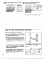
1. Hold thB treedmi]l with your hands in the locations shown
at the right. To decrease the possibility of injury, bend
your legs and keep your back straight. As you raise
the treadmill, make sure to lift with your legs rather
than your back. Raise the treadmill about halfway to the
vertical position.
2. Move your right hand to the position shown and hold the
treadmill firmly. Raise the treadmill until the storage latch
closes over the catch. Make sure that the storage latch
is fully engaged over the catch.
To Frotect the floor or carpet from damage, place a
mat under the treadmill.
Keep the treadmill out of
direct sunlight. Do not leave the treadmill in the storage position in temperatures above 85 ° Fahrenheit.
10
HOW TO MOVE THE TREADMILL
Before moving the treadmill, convert the treadmill to the storage position as descTibed above. Make sLIre that the storage latch is closed fully over the catch.
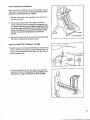
1. Hold the upper ends of the handrails,
the base as shown.
Place one foot on
2. Tilt the treadm[l] back until If rolls freely on the front
wheels, Carefully move the treadmill to the desired location• Never move the treadmill without tipping it back,
or the b_se pads may come off. TO reduce the risk of
injury, us_ extreme caution while moving the treadmill. Do not move the treadmill over an uneven
surface.
3. Place one foot on the base, and carefully lower the treadmill until it is testMg Jnthe _tcrage pDs_gon.
HOW TO LOWER THE TREADMILL
FOR USE
1. Hold the upper end of the treadmiU with your r_ght hand as
shown. Using your ]eft thumb, press the storage latch and
hold it. Pivot the treadmill Lmtil the frame and foot rail are
past the storage latch.
2. Hold the treadmill firmly with both hands, and lower the
treadmill to the floor. To decrease the possibility of injury, bend your IDgs and keep your back straight.
11
m
MAINTENANCE
AND TROUBLE-SHOOTING
Most treadmill problems can be solved by following the steps below. Find the symptom that applies, and
follow the steps listed, if furlher assistance is needed, please call our Customer Service Department togfree at 1-800-999-3756,
Monday through Friday, 6 a.m. until 6 p.m. Mountain Time (excluding holidays).
1. SYMPTOM:
THE POWER DOES NOT TURN ON
a. Make sure that the power cord is plugged into a surge protector, and that the surge protector is plugged into
a properly grounded outlet. (See HOW TO PLUG IN THE POWER CORD on page 7) Use only a ULdisfed
surge protector, rated at 15 amps, with a 14-gauge cord of five feet or less in length.
b. After the power cord has been plugged
in, make sure that the key is fully inserted
into the console.
(See step
1 on page g.)
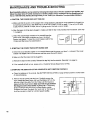
c. Check the circuit breaker located on the treadmill
near the
power cord. If the switch protrudes as shown, the circuit
breaker has tripped. TO reset the clrcuit breaker, wait for five
minutes and then press the switch back in.
2. SYMPTOM:
THE POWER TURNS OFF DURING
USE
a. Check the circuit breaker located on the treadmill frame near the power cord (see 1. c. above). If the circuit
breaker has tdppod, wait for five minutes and then press the switch back in.
b, Make sure that the power cord is plugged in.
c. Remove the key from the console.
Reinsert the key fully into the console.
d If the treadmill still will not run, please call our Customer
3. SYMPTOM;
THE DISPLAYS
OF THE CONSOLE
a. Check the batteries in the console.
of drained batteries
Service Department,
DO NOT FUNCTION
See BATTERY
INSTALLATION
h. Remove the six screws from the hood. Carefully remove the
hood. Locate the Reed Switch (86) and the Magnet (67) on the
left side of the Pulley (85). Turn the Pulley until the Magnet is
aligned with the Reed Switch. Make sure that the gap between
the Magnet and the Reed Switch is about 1/8". If necessary,
loosen the Screw (63) and move the Reed Switch slightly.
Retighten the Screw. Re-attach the hood, and run the treadmill
for a few minutes to check for a correct speed reading.
12
(See step 1 on page 9.)
toll-free.
PROPERLY
on page 8. Most problems
are the result
i
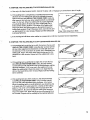
4. SYMPTOM: THE WALKING BELT SLOWS WHEN WALKED ON
a. Use only a ULdisted surge protector, rated at 15 arnp8, with a 14-gauge cord of five feet or less in length.
b. If the walking belt is o_,edlghtened, treadmill performance may
decrease and the walking belt may be perrnanenlty d_roaged.
Remove the key and UNPLUG THE POWER CORD. Using the
allen wrench, turn both rear roller adjustment bolts counterclockwise, 1/4 of a turn. When the walking belt is properly tightened,
you should be able to lift each side of the walking belt 3 to 4
inches off the walking platform. The center Of the walking belt
should just touch the walking platform. Be careful to keep the
walking belt centered. Plug in the power cord, insert the key and
run the treadmilr for a few minute@. Repeat until the walking belt
is properly tightened.
¢. If the walking
5. SYMPTOM:
belt still alows when walked on, please call our toll-free Customer
THE WALKING
BELT IS OFF-CENTER
WHEN WALKED
Service Depadment.
ON
a. If the walking belt has shifted to the left, first remove the key and
UNPLUG THE POWER CORD. Using the allen wrench, turn the
left rear roller adjustment bolt c]ockwise, and the dgth bolt counterclockwise, 1/4 of a turn each. Be carefur not to overtlghten the
walking belt. Plug in the power cord, insert the key and run the
treagroiil for a few roinutes. Repeat until the walking bait is centered.
b. If the walking belt has shifted to the dght, first remove the key
and UNPLUG THE POWER CORD. Using the allen wrench,
turn the left rear miler adjustroect bolt counterclockwise, and the
right bolt clockwise, 1/4 of a turn each. Be careful not to overtighten the walking belt, Plug in the power cord, insert the key
and run the treadmill for a few minutes. Repeat until the walkthg
belt is centered.
¢. If the walking belt allpo when walked on, first remove the key
and UNPLUG
THE POWER
CORD, Using the allenwrench,
turnbeth rear roller
adjustmect beltsclocl_'_ise,
I/4 of a turn,
When the walking beltIscorreclly
tightened,you should be able
to lift
each side of the walkingbelt3 to4 inches of_the waI_ng
platform.
Tn_ centerofthe walking bertshould justtouch the
welkingpi_orm. Be carefulto Keep the walking beltcentered.
Plug inthe power oord,Insert
the key and ru_ the treadmill
fora
few minutes.Repeat _nltt
the wa_ing belt_ pmpo_y tightened.
I@
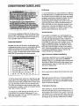
CONDiTiONiNG GUIDELINES
Fat Burning
To burn fat effectively, you must exercise at a relatively
low intensity level for a sustained period of time. During
the first few minutes of exercise, your body uses easily
accessible carbehydrate calories for energy. Orgy after
the first few minutes does your body begin to use
stored fat calories for energy. If your goal is to burn fat,
adjust the speed and incline of the treadmill until your
heart rate is near one of the lower two numbers in your
training zone. It may also be helpful to set the speed
control on the console to FAT BURN to help you maintain the proper intensity level. (See page 9.)
Aerobic Exercise
The following guidelines will help you to plan your exercise program. Remember--these
&re genera] guidelines only. For more detailed exemlse information, obtain a reputable book or consult your physician.
EXERCISE
INTENSITY
Whether your goal is to burn fat or to strengthen your
cardiovascu]ar system, the key ta achieving the desired
results _sto exercise with the proper intensity. The
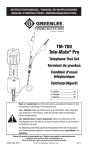
proper intensity level can be found by using your heart
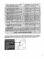
rate as a guide. The chart below shows recommended
hear[ rates for fat burning and aerobic exercise.
ECCC}
ECCC]EC3
CC C]CC]
I
A3e
II
20
ECCCC]
ii ECCCC3
I1--11
A0
50
I e_
Athletfo Conditioning
If your goal is high performance athletic conditioning,
set the speed control on the conso]e to PERFORMANCE to help you maintain the proper intensity level.
(See page 9.) Note: During the first few weeks of your
exercise p_ogram, keep your heart rate near the low
end of your training zone,
4*0
70
Each workout should include the following
80
TO find the proper head rate for you, first find your age
at the bottom of the chart (ages are rounded off to the
nearest ten years). Next, find the three numbers above
your age. The three numbers are your '1raining zone. _
The lower two numbers are recommended
heart rates
for fat burning; the higher number is the recommended
heart rate for aerobic exercise•
To measure your hear[ rate during exercise, use the
pulse sensor on the eonsole_ (See page 9.) P your
heart rate is too high or too low, adiuat the speed or incline of the treadmill as needed,
14
High Parfonnance
WORKOUT GUIDELINES
II
30
[f your goal is to strengthen your cardiovascular
system, your exercise must be "aerobic," Aerobic exercise
is activity that requires large amounts of oxygen for
prolonged periods of time. This increases the demand
on the heart to pump blood to the muscles, and on the
lungs to oxygenate the blood, For aerobic exercise,
adjust the speed and incline of the treadmill until your
heart rate is near the higher number in your training
zone. It may also be helpful to set the speed control on
the console to AEROBIC to help you maintain the
proper int e n si'_y level. (See page 9.)
three pads:
A Warm-up
Start each workout with 5 to 10 mlnutes of stretching
and light exercise. A proper warm-up increases your
body temperature, heart rate, and circulation in preparation for strenuous exercise.
Training
Zone Exercise
After warming up, increase the intensity of your exercise until your heart rate is in your training zone for 20
to 60 minutes. (During the first few weeks of your exer
cise program, do not keep your heart rate in your training zone for longer then 20 minutes.) Breathe regularly
and deeply as you exercisemnever
hold your breath.
A Cool-down
Exercise Frequency
Finish each workout with 5 to 10 minutes of stretching
TO maintain or improve your condition, complete three
workouts each week, with at least one day of rest be*
tween workouts. After _.few mor3ths of regular exercise, you may complete up to f_veworkouts each week
if desired. The key to success is to make exercise a
regular and enjoyable part of your _verydey life.
to cool down. This will increase the flexibility of your
muscJes and wJ]l heJp to prevent post-exercise problems.
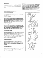
SUGGESTED
STRETCHES
The correct form for several basic stretches
drawings
is shown in the
below. Move slowly as you stretch--no€or
bounce.
1. Toe Touch Stretch
Stand with your knees bent slightly and slowly bend forward
from your hips. AIIow your back and shoulders to relax as you
reach down toward your toes as far as possible. Hold for 15
counts, then relax. Repeat 3 times. Stretches: Hamstrings,
back of knees and back.
2. Hamstring
t
2
Stretch
Sit with one leg extended. Bdng the sole of the opposite foot
toward you and rest it agafnst the inner thigh of your extended
leg. Reach toward your toes as far as bossible. Hold for 15
counts, then relax. Repeat 3 times for each leg. Stretches:
Hamstrings, lower back and groin.
3, Calf/Achilles
Stretch
With one leg in front of the other, reach fo_,,'ard and place your
hands against a wall. Keep your beck leg straight and your
back rapt fl_t on the floor. Bend your front leg, lean forward and
move your hips toward the wall. Hold for 15 counts, then relax.
Repeat 3 times fat each leg. To cause further stretching of the
achilles tendons, bend your back leg as well. Stretches:
Calves, aohilles tendons and ankle_.
4. Quadrieeps
t
4
Stretch
With one hand against a wall for balance, reach back and
grasp one toot with your other hand. Bring y_ur heel a_ close
to your buttocks as pos_lble. Hold for 15 counts, ther_ relax.
Repeat 3 times for each leg. Stretches: Quadriceps and hip
m{Jsoies.
5. Inner Thigh Stretch
Sit with the soles of your feet together and your knees outward.
Pull your feet toward your groin area as far as possible. Hold
{or 15 counts, then rela_x. F::lepest3 times. Strelches:
QuaG'rlcep$ and hip muscles
15
ORDERING REPLACEMENT
PARTS
To order replacement parts, call our Customer Service Department toll-tree at 1=80g-999-3756, Monday through
Friday, 6 a,m. until 6 p.m. Mountain Time (e×ciuding hondays). When ordering parts, please be prepared to gwe
the following information:
• The MODEL NUMBER
OF THE PRODUCT
• The NAME OF THE PRODUCT
• The SERIAL NUMBER
• The KEY NUMBER
(WLTL42570).
(WESLO CADENCE _ LX25 treadmill).
OF THE PRODUCT
(see the front cover of this manual).
OF THE PART(S)
(see the EXPLODED
OF THE PART(S)
(see the EXPLODED
DRAWING
and PART L]ST attached
to the center
of this manual).
= The DESCRIPTION
of this manual).
If possible,
place the treadmill near your telephone
WESLO is a registered
DRAWING
for easy reference
trademark
and PART LIST attached to the center
when calling,
of ICON Health & Fitness, Inc.
LIMITED WARRANTY
ICON Health & Fitness, Inc. (ICON), warrants this product to be free from detects in workmanship and
matedel, under normal use and service conditions, for a period of ninety (90) days from the date of put:base. This warranty extends only to the odgina] purchaser. ICON's obligation under this warranty is limited to replacing or repairing, at ICON's option, the product at one of its authorized sewice centers. All
iroduuts for which warranty claim is made must be received by [CON at one of its authorized service
centers with all freight and other transportation
charges prepaid, accompanied by sufficient proof of purchase, All returns must be pre-authodzed
by ICON. This warranty does not extend to any product or
damage to a product caused by or attributable to freight damage, abuse, misuse, improper or abnormal
usage or repairs not provided by an lOON authodzed service center, to products used for commercial or
rental purposes, or to products used as stere display models. No other warranty beyond that 8pecitically
set forth above is authorized by ICON.
ICON is not responsible or liable for indirect, special or consequential damages arising out of or in connection with the use or performance of the product or damages with respect to any economic loss. loss
of property, less of revenues or profits, loss of enjoyment or use, costs of removal, installation or other
consequential damages of whatsoever nature. Some states do not allow the exclusion or limitation of incidental or consequential damages. Accordingly, the above limitation may not apply to you.
The warranty extended hereunder is in lieu of any and all other warranties and any implied warranties of
merchantability
or fitness for a particular puq3ose is limited in its scope and duration to the terms set
forth herein. Some states do not allow limitations on how long an implied warranty lasts. Accordingly,
the above limitation
may not apply to you.
This warranty gives you specific legal rights. YOU may also have other rights which vary from state to state.
ICON HEALTH
Part No. 140263
G0300'2AC
& FITNESS,
R0997B
INC., 1500 S. 1000 W., LOGAN,
UT 84321"9813
Printed in USA © 1997 ICON Health & Fitness, Inc.