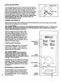
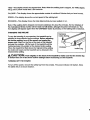
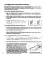
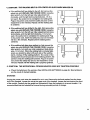
1
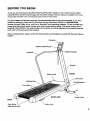
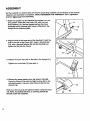
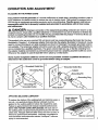
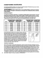
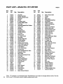
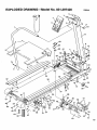
®
0-8MPH° 1.5HP° ADJUSTABLE
INCLINE
OWNER'S MANUAL
°
Model No. 831.297420
Serial No.
The serial number can be found in the
location shown below. Write the serial
number in the space above.
I
Sedal Number Decal
_l_CAUTION!:
Read all safety
and instructions
precautions
in this
manual
using
before
equipment.
Keep
this
this
manual
in a safe place
future
reference.
for
SEARS,
ROEBUCK
AND CO., HOFFMAN
ESTATES,
IL 60179
FULL 90 DAY WARRANTY
For 90 days from the date of purchase, when proper assembly and maintenance procedures
detailed in the Owner's Manual are followed, SEARS will, free of charge, repair or replace and
install a replacement
part for any defective part, when this treadmill is used in a normal manner.
This warranty does not apply when this treadmill is used for commercial or rental purposes.
SERVICE IS AVAILABLE
CENTEPJDEPARTMENT
SIMPLY BY CONTACTING
IN THE UNITED STATES.
YOUR NEAREST
SEARS
SERVICE
This warranty gives you specific legal rights, and you may also have other rights which vary
from state to state.
SEARS,
ROEBUCK AND CO., DEPT. 817WA,
HOFFMAN ESTATES, IL 60179
®
0-8MPH• 1.5HP* ADJUSTABLE
INCLINE
TABLE OF CONTENTS
IMPORTANT SAFETY
BEFORE YOU BEGIN
PRECAUTIONS
.................................................
.....
".........................................................
4
5
ASSEMBLY
.......................................................................
OPERATION
AND ADJUSTMENT
.....................................................
TROUBLE-SHOOTING
AND STORAGE
......................................
CONDITIONING
GUIDELINES
...................................................
PART LIST ......................................................................
EXPLODED
DRAWING
............................................................
ORDERING
REPLACEMENT
_I_WARNING:
This is especially
PARTS
:..
.........................................
Before beginning
important
•.........
for persons
this or any exercise
6
7
10
12
14
15
Back Cover
program,
over the age of 35 or persons
consult your physician.
with pre-existing
problems.
Read all instructions before using. SEARS assumes no responsibility
injury or property damage sustained by or through the use of this product.
health
for personal
3
IMPORTANT SAFETY PRECAUTIONS
WARNING:
To reduce the risk of burns, fire, electric shock or injury to persons,
read the following important safety precautions and information before operating the treadmill.
1. Position the treadmill on a level surface, with at least 8 feet of clearance behind the treadmill. Do not place the treadmill near water, outdoors or on a surface that blocks any air
opening. Do not operate where aerosol products are used or where oxygen is being administered.
2. When connecting the power cord (see OPERATION
power cord directly into s grounded circuit capable
appliances should be on the same circuit. Keep the
If an extension cord is needed, use only a 14-gauge
in length with a three-wire conductor.
AND ADJUSTMENT on page 7), plug the
of carrying 12 or more amps. No other
power cord away from heated surfaces.
general-purpose cord of five feet or less
3. Never move the walking belt while the power is turned off. Do not operate the treadmill if the
power cord or plug is damaged, or if the treadmill is not working properly. (See BEFORE
YOU BEGIN on page 5 if the treadmill is not working properly.)
4. The roller guards must be 1/8 inch from the rear roller. Turn the power off and adjust the
roller guards, if necessary.
5. Wear appropriate exercise attire when using the treadmill. Do not wear loose clothing that
could become caught in the treadmill. Always wear running shoes. Never use the treadmill
with bare feet, wearing only stockings or in sandals. Athletic support clothes are recommended for both men and women.
6. Never allow more than one person on the treadmill at a time. The treadmill should be used
only by persons weighing 250 pounds or less.
7. Never start the treadmill while you are standing on the walking belt. Always hold the
handrail when exercising on the treadmill.
8. Keep small children away from the treadmill at all times. Never leave the treadmill unattended while it is running. Always remove the safety key when the treadmill is not in use.
9. Never drop or insert any object into any opening.
10. To reduce the possibility of overheating, do not operate the treadmill continuously for
longer than I hour.
11. The treadmill is capable of high speeds. Adjust the speed slowly to avoid sudden jumps in
speed.
12. Use the treadmill only as described in this manual.
13. Always unplug the power cord before performing the maintenance and adjustment procedures described in this manual. Never remove the motor hood unless instructed to do so by
an authorized service representative. Servicing other than the procedures in this manual
should be performed by an authorized service representative only.
4
SAVE THESE INSTRUCTIONS
BEFORE
YOU
BEGIN
Thank you for selecting the SEARS LIFESTYLEFP 8.0 MPH treadmill. The LIFESTYLER 8.0 MPH
treadmill blends advanced technology with innovative design to let you enjoy an excellent form of cardiovascular exercise in the convenience and privacy of your home.
For your safety and benefit, read this manual carefully before using the treadmill, if you have
additional questions, please call our Customer Service Department toll-free at 1-800-999-3756,
Monday through Friday, 6 a.m. until 6 p.m. Mountain Time (excluding holidays). To help us assist you,
please note the product model number and serial number before calling. The model number of the
treadmill is 831.297420.
The serial number can be found on a decal attached to the treadmill (see the
front cover of this manual for the location).
Before reading further, please review the drawing below and familiarize
labeled.
yourself with the parts that are
Speed
FRONT
Motor Hood
Walking
Circuit Breaker
•
Foot Rails.
RIGHT
SIDE
Power Cord
BACK
Rear Roller
Adjustment Bolts
Incline Leg
5
ASSEMBLY
Set the treadmill in a cleared area and remove all packing materials. Donot dispose of the packing
materials until assembly is completed. TOOLS REQUIRED FOR ASSEMBLY: An 8 = adjustable
wrench
_
(not included).
1. Raise the Upright (11) and Handrail (not shown), to a vertical position. Insert the Lock Knob (13), with the Lock
Knob Washer (14), into the Upright and turn the Knob
clockwise until it is almost tight. Leave a little play in the
Upright for the following steps.
2. Align the hole in the lower end of the Handrail (1) with the
hole in the side of the Frame (37). Insert a Handrail Bolt
(74), with a Handrail Washer (9), into the Handrail and
tighten the Bolt into the Frame.
1
3. "13ghtenthe Acorn Nut (10) on the side of the Upright (11).
"13ghtenthe Lock Knob (13) (see step 1).
11
4. Remove the paper backing from the Wrench Clip (68).
Press the Wrench Clip onto the Right Endcap (64) in the
indicated location. Press the Alien Wrench (66) into the
Wrench Clip.
Make sure that all parts are tightened before using the treadmill. Note: To protect the floor, a covering should be
placed under the treadmill.
6
68
66
37
OPERATION AND ADJUSTMENT
PLUGGING IN THE POWER CORD
This product must be grounded.
If it should malfunction or break down, grounding provides a path of
least resistance for electric current to reduce the risk of electric shock. This producLis equipped with a
cord having an equipment-grounding
appropriate
outlet
and ordinances.
that is properly
DANGER:
conductor and a grounding plug. Plug the power cord into an
Installed
and grounded
in accordance
with all local codes
Improper connection of the equipment-grounding conductor can result in a risk
of electric shock. Check with a qualified electrician or serviceman if you are in doubt as to whether the
product is propedy grounded. Do not modify the plug provided with the product--if it will not fit the outlet, have a proper outlet installed by a qualified electdcian.
This product is for use on a nominal 120-volt circuit, and has a grounding plug that looks like the plug
illustrated in Drawing 1. A temporary adapter that looks like the adapter illustrated in Drawing 2 may be
used to connect this plug to a 2-pole receptacle as shown in Drawing 2 if a propedy grounded outlet is
not available. The temporary adapter should be used only until a properly grounded outlet (Drawing 1)
can be installed by a qualified electdcian. The green colored rigid ear, lug, or the like extending from
the adapter must be connected to a permanent ground such as a propedy grounded outlet box cover.
Whenever the adapter is used it must be held in place by a metal screw.
Some 2-pole receptacle Outlet box covers are not grounded. Contact a qualified electrician to
determine if theoutlet box cover is grounded before using an adapter.
Grounded Outlet Box
2
_munded
Outlet Box
Grounding Plug
Grounding Pin
Grounding Plug
=gPin
•Grounded Outlet
APPLYING
SILICONE
LUBRICANT
To reduce the friction of the walking belt and minimize wear, a
non-oil-, non-petroleum-base
silicone lubricant must be
Apply lubricant
to the entire
shaded area.
applied to the walking platform before the treadmill is used.
Failure to apply lubricant will reduce treadmill performance.
WITH THE POWER CORD UNPLUGGED,
lift each side of
the walking belt and spray lubricant generously onto the indicated area. Reapply lubricant after every ten hours of use, or
whenever performance decreases. Lubricant is available at
most hardware and automotive stores. Uni°Sport TM silicone
spray is recommended.
Silicone
Lubricant
7
INSTALLING BAI-rERIES
Battery Cover
The motivational fitness monitor requires two "AA" batteries
(not included); alkaline batteries are recommended. Slide the
battery cover open. Remove the battery clip from the console. Find the markings inside the battery clip showing which
direction the batteries should be tumed. Press the batteries
into the battery clip• Replace the battery clip in the console
and close the battery cover. Note: If there is a sheet of protective plastic on the face of the console, peel it off
before operating the console.
Battery Clip
TURNING THE POWER ON
Step onto the foot rails of the treadmill. Locate the clip attached by a cord to the safety key, and slide
the c!ip onto the waistband of your clothing.
a= CAUTION:
oo not stand on the walking
belt while turning
the power on. Always
the clip while operating the treadmill; if you fall, the safety key will be pulled from the power
switch, Instantly turning the power off.
Insert the safety key into the power switch.
The power indicator will light. The four displays of the motivational fitness monitor will
not appear until the ON/RESET button is
pressed, or the walking belt begins to move
(see CONTROLLING THE SPEED below).
Note: If batteries were just installed, the four
displays will already appear.
CONTROLLING
THESPEED
ACCUSMART
Mo'rlvA_O_L
Motivational
Fitness _
Monitor
To start the walking belt, first turn the speed
control knob to "RESET." Then, turn the
knob slowly clockwise until the walking belt
begins to move at slow speed.
a= CAUTION:
After the knob is
turned, there will be a pause before the
walking belt begins to move• Adjust the
speed slowly until you are familiar with the
operation of the treadmill.
Carefully step onto the walking belt and begin
exercising. Change the speed of the walking
belt as desired by tuming the speed control
knob• To stop the walking belt, turn the knob
to "RESET."
Speed
Control Knob
Power Switch
Power
MOTIVATIONAL RTNESS MONITOR
The four displays of the motivational fitness
monitor provide continuous exercise feed-
8
backl The displays can be reset by pressing
the ON/RESET
button. The four displays are
described below:
Safety
FITNESS
MONIll_R
wear
TIME--This
display shows the elapsed time. Note: When the walking belt is stopped, the TIME display
will go into a pause mode after a few seconds.
CALORIE--This
SPEED--This
display
display
DISTANCE--This
shows the approximate
number of nutritional Calories
that you have burned.
shows the current speed of the walking belt.
display shows the total distance that you have walked or run.
Note: If the walking belt is stopped and remains stationary for about five minutes, the four displays of
the motivational fitness monitor will be reset and will darken, although the power will remain on. The
four displays will appear again when the ON/RESET button is pressed, or the walking belt is restarted.
CHANGING THE INCLINE
Decrease
To vary the intensity of your exercise, the treadmill can be
adjusted to three different "incline settings. Before adjusting
the incline setting, turn off the power and unplug the
power cord. Stand on the floor at the back of the treadmill
and grip the endceps. Lift the back of the treadmill until the
incline leg locks into position at the desired incline setting.
When the treadmill is lifted above the highest incline setting,
the incline will reset and the treadmill can be lowered to the
lowest incline setting.
Incline Setting
CAUTION:
Push slightly on the back of the treadmill to make sure that the incline leg
is locked into one of the three Incline settings before exercising on the treadmill.
TURNING
OFF THE
POWER
To turn off the power, remove the safety key from the console. The power indicator will darken. Store
the safety key in a secure location.
9
TROUBLE-SHOOTING AND STORAGE
Most treadmill problems can be solved by following the simple steps below, Find the symptom
that applies to your treadmill and follow the steps listed. If further assistance is needed, please call our
Customer Sewice Department toll-free at 1-800-999-3756,
Mountain Time (excluding holidays).
1. SYMPTOM:
Monday through Friday, 6 a.m. until 6 p.m.
THE POWER DOES NOT TURN ON
d, Make sure that the power cord is plugged into a properly grounded outlet. (See OPERATION
_'_AND ADJUSTMENT on page 7.) If an extension cord is needed, use only a 14-gauge generalpurpose cord of five feet or less in length.
b. After the power cord has been plugged in, make sure that the safety key is fully inserted into the
console. Various indicators on the console should light. (See OPERATION AND ADJUSTMENT
on parle 7.)
C,
Check the circuitbreaker located on the treadmill
frame near the power cord. If the switch protrudes as
shown, the circuit breaker has tripped. To reset the circuit breaker, wait for five minutes and then press the
switch back in.
Tripped
2. SYMPTOM:
THE POWER
TURNS
OFF DURING
Reset
USE
a. Check the circuit breaker located on the treadmill frame near the power cord. If the circuit breaker
has tripped, the switch will protrude. (See the drawing above.) To reset the circuit breaker, wait
for five minutes and then press the switch back in.
b. Make sure that the power cord is plugged in.
c. Remove the safety key from the console. Reinsert the safety key fully into the console. Various
indicators on the console should light.
3. SYMPTOM:
THE WALKING BELT SLOWS WHEN WALKED ON
a. Apply silicone lubricant to the walking platform before use. Reapply
lubricant after every 10 hours
of use, and whenever a decrease in performance is noticed. (Uni.Sport silicone spray is recommended.) CAUTION:
UNPLUG THE POWER CORD WHEN APPLYING LUBRICANT.
(See
OPERATION
AND ADJUSTMENT
on page 7 application instructions.)
b. If an extension
cord is needed, use only a 14-gauge general-purpose
c. If the walking belt is overtightened,
treadmill
cord of five feet or less in length.
performance
may decrease and the walking belt may be permanently
damaged. Remove the safety key and UNPLUG THE
POWER CORD. Using the allen wrench, turn both rear
roller adjustment
bolts counterclockwise,
1/4 of a turn.
When the walking belt is properly tightened, you should
be able to lift each side of the walking belt 3-4 inches off
10
the walking platform. The center of the walking belt should
be just above the walking platform. Be careful to keep the
walking belt centered. Plug in the power cord, insert the
safety key and run the treadmill for a few minutes. Repeat
until the walking belt is properly tightened.
Rear Roller Adjustment
Bolts
4. SYMPTOM:
THE WALKING BELT IS OFF-CENTER OR SLIPS WHEN WALKED ON
a. If the walking belt has shifted to the left, first remove the
safety key and UNPLUG THE POWER CORD. Using the
allen wrench, turn the left rear roller adjustment bolt
clockwise, and the right bolt counterclockwise, 1/4 of a
turn each. Be careful not to overtighten the walking belt.
Plug in the power cord, insert the safety key and run the
treadmill for a few minutes. Repeat untilthe walking belt
is centered.
b. If the walking belt has shifted to the dght, first remove the
safety key and UNPLUG THE POWER CORD. Using the
allen wrench, tum the left rear roller adjustment bolt coun*
terclockwise, and the right bolt clockwise, 114 of a turn
each. Be careful not to overtighten the walking belt. Plug
in the power cord, insert the safety key and run the treadmill for a few minutes. Repeat until the walking belt is
centered.
a
b
c. If the walking belt slips when walked on, first remove the
safety key and UNPLUG THE POWER CORD. Using the
allen wrench, turn both rear roller adjustment bolts clockwise, 1/4 of a turn. When the walking belt is correctlytightened, you should be able to lift each side of the walking
belt 3-4 inches off the walking platform. The center of the
walking belt should be just above the walking platform. Be
careful to keep the walking belt centered. Plug in the power
cord, insert the safety key and run the treadmill for a few
minutes. Repeat untilthe walking belt is properly tightened.
5. SYMPTOM:
THE MOTIVATIONAL
FITNESS
MONITOR
DOES NOT FUNCTION
PROPERLY
a. Check the batteries in the console. (See INSTALLING BA'n'ERIES on page 8.) Most problems
are the result of drained batteries.
STORAGE
Unplug the power cord when the treadmill is not in use. Remove the bolt and washer from the lower
end of the handrail. Loosen the nut at the upper end of the handrail. Loosen the lock knob at the front
of the upright. Carefully lay the upright on the treadmill. Keep the hardware in a secure location. It is
recommended that the treadmill be covered during extended periods of storage.
11
CONDITIONING
GUIDELINES
The following guidelines will help you to plan your exercise program. Remember that proper nutrition
and adequate rest are essential for successful results.
I WARNING:
Before beginning this or any exercise program, consult your physician.
This is especially important for individuals over the age of 35 or individuals with pre-existing
health problems.
EXERCISE INTENSITY
To maximize the benefits of exercising, it is important to exercise with the proper intensity. The proper
intensity can be found by using your heart rata as a guide, For effective aerobic exercise, your heart
rate should be maintained at a level between 70% and 85% of your maximum heart rate as you exercise. This is known as your training zone. You can find your training zone in the table below.
Training zones are listed for both unconditioned and conditioned persons according to age.
AGE
UNCONDITIONED
TRAINING ZONE
(BEATS/MIN)
CONDITIONED
TRAINING ZONE
(BEATS/MIN)
2O
136-167
25
AGE
UNCONDITIONED
TRAINING ZONE
(BEATS/MIN)
CONDITIONED
TRAINING ZONE
(BEATS/MIN)
133-162
55
127-155
122-149
136-166
132-160
• 60
126-153
121-147
30
135-164
130-158
65
125-151
119-145
35
134-162
129-156
70
123-150
118-144
40
132-161
127-155
75
122-147
117-142
45
131-159
125-153
80
120..146
115-140
50
129-156
124-150
85
118-144
114-139
During the first few months of your exercise program, keep yOur
heart rate near the low end of your training zone as you exercise.
After a few months, your heart rate can be increased gradually
until it is near the middle of your training zone as you exercise. To
measure your heart rate, stop exercising and place two fingers on
your wdst. Take a six-second heartbeat count, and multiply the
result by 10 to find your heart rate. For example, if your six-second
heartbeat count is 14, your heart rate is 140 beats per minute. (A
six-second count is used because your heart rate will drop rapidly
when you stop exercising.) Adjust the intensity of your exercise
until your heart rate is at the proper level.
"-_._._/
_._
WORKOUT GUIDELINES
Each workout should consist of three basic parts: a warm-up, 20 to 30 minutes of training zone exercise, and a cool-down. Warming up prepares the body for exercise by increasing circulation, delivering
more oxygen to the muscles and raising the body temperature. Begin each workout with 5 to 10 minutes of stretching and light exercise to warm up. Then, increase the intensity of your exercise to raise
your heart rate to your training zone for 20 to 30 minutes. Breathe regularly and deeply as you exercise-never
hold your breath. Finish each workout with 5 to 10 minutes of stretching to cool down. This
12
will increase the flexibility of the muscles, and reduce soreness and other post-exercise problems.
To maintain or improve your condition, complete three workouts each week, with at least one day of
rest between workouts. After a few months of regular exercise, you may complete up to five workouts
each week, if desired. The key to success is CONSISTENCY.
SUGGESTEDSTRETCHES
The followingstretchescan providea goodwarm-upor cool-down.Correctformfor eachstretchis
shownin the drawingsbelow.Moveslowly as you stretch---never bounce.
TOE TOUCH
STRETCH
Stand with your knees bent slightly and slowly bend forward from your hips. Allow your back and shoulders to
relax as you reach down toward your toes as far as possible. Hold for 15 counts, then relax. Repeat 3 times.
Stretches: Hamstrings, back of knees and back.
HAMSTRING
STRETCH
Sit with one leg extended. Bring the sole of the opposite
foot toward you and rest it against the inner thigh of your
extended leg. Reach toward your toes as far as possible.
Hold for 15 counts, then relax. Repeat 3 times for both
legs.
Stretches: Hamstrings, lower back and groin.
CALF/ACHILLES
STRETCH
With one leg in front of the other, reach forward and place
your hands against a wall. Keep your back leg straight
and your back foot flat on the floor. Bend your front leg,
lean forward and move your hips toward the wall. Hold for
15 counts, then relax. Repeat 3 times for both legs. To
cause further stretching of the achilles tendons, bend
your back leg as well.
Stretches:
Calves,
QUADRICEPS
achilles tendons
and ankles.
STRETCH
With one hand against a wall for balance, reach back and
grasp one foot with your other hand. Bring your heel as
Close to your buttocks as possible. Hold for 15 counts,
then relax. Repeat 3 times for both legs.
Stretches:
INNER
Quadriceps
THIGH
and hip muscles.
STRETCH
Sit with the soles of your feet together
and your knees
outward. Pull your feet toward your groin area as far as
possible. Hold for 15 counts, then relax. Repeat 3 times.
Stretches:
Quadriceps
and hip muscles.
13
PART LISTuModel
14
No, 831.297420
R894A
Key
No,
Pa_
No.
Qty.
Handrail
44
100541
2
Motor Swivel Bolt
1
1
1
9
Safety Key/Clip
Speed Control Knob
Console
Screw
45
46
47
48
031238
120647
105477
1
1
2
Choke
Motor
Motor Nut
113203
116131
1
1
6" Cable Loom
Power Switch Wire
49
50
108276
102959
1
2
Pulley/Flywheel/Fan
Small Bolt
8
9
10
012149
014132
114268
1
5
1
Pivot Nut
Handrail Washer/Pivot Washer
Acorn Nut
51
52
53
013547
120655
012152
4
2
4
incline Leg Bolt
incline Leg Spring
Small Nut
11
12
119350
120003
1
1
Upright
Pivot Bolt
54
55
014087
120663
013300
4
2
5
incline Leg Washer
incline Leg Latch
Hood Bracket Screw
13
14
15
017088
014156
012056
1
1
2
Upright Knob
Upright Washer
Lock Nut
56
57
58
120656
4
incline Leg Spacer
012108
120746
4
2
Incline Leg Nut
incline Leg Cap
16
17
18
031229
113204
019084
1
1
1
Power Cord
12" Cable Loom
Grommet
59
60
61
120657
119503
1
1
incline Leg
Controller/Choke
19
20
21
111869
109382
113106
1
1
5
Upright Cage Nut
Circuit Breaker
Hood Anchor
62
63
64
114261
016057
016029
1
4
2
Ground Wire
8" Cable "lJe
4" Cable "lJe
22
23
24
25
26
013088
112609
014127
052014
117806
10
1
2
2
2
Safety Cover Screw
Front Roller Adj. Bolt
Adjustment Washer
Front Wheel
Front Wheel Bolt
65
66
67
68
69
119348
013206
045010
1
2
1
Right Endcap
Rear Roller Adj. Bolts
Allen Wrench
119347
016028
1
2
Left Endcap
Wrench Clip
27
28
012082
118153
1
1
Tension Nut
Reed Switch/Sensor
70
71
113050
109788
010206
2
1
2
Rear Roller Spacer
Rear Roller
Roller Guard
29
30
118332
109265
1
2
Extension Wire
Belt Guide
72
73
013162
100691
2
6
Roller Guard Screw
Platform Screw
31
32
013423
120649
8
2
Guide Screw/Leg
Foot Rail
74
75
112001
120645
1
1
Handrail Bolt
Motor Hood w/Decal
33
117841
1
Safety Cover
76
34
35
117273
120526
1
1
Front Roller/Pulley
Walking Platform
77
78
111430
114355
115809
1
1
1
Handrail Cage Nut
Front Roller Spacer
Belt
36
37
120525
NSP
1
1
Walking Belt
Frame
79
80
016055
116890
1
1
Wire Clip
Tabbed Washer
38
39
40
41
103855
121637
100994
108080
1
1
2
8
J-Bolt
Motor Swivel
Motor Bolt
Small Screw
81
82
83
#
014041
2
Tension Washer
104514
120527
1
2
Tension Spring
Platform Shim
42
43
109786
014073
1
2
Controller
Motor Swivel Washer
118204
119407
1
1
8" Blue Jumper Wire
Owner's Manual
Key
No.
Pad
No.
Qty.
1
114218
1
2
3
4
5
114575
110000
120650
108404
6
7
Description
Wire
Screw
Note: "#" indicates a non-illustrated
part. Specifications
back cover for information about ordering replacement
#
are subject
parts.
Description
Plate
to change without notice. See the
EXPLODED DRAWING-:-' Model No. 831.297420
R894A
5_
9
,10
_11
9
12
7
13
19
17
77
74
75
2O
9
i
35
32
36
23
!
8O
\
30
15
26
37
70
31
71
24
66
52
59
58
31 54
15
ORDERING REPLACEMENT
PARTS
Each TREADMILL has its own MODEL NUMBER. Always mention this MODEL NUMBER when
requesting service or repair parts for your TREADMILL.
All parts listed herein can be ordered through SEARS, ROEBUCK AND CO. SERVICE CENTERS and
most SEARS RETAIL STORES. If parts you need are not stocked locally, your order will be tiansmitted
to a SEARS PARTS DISTRIBUTION CENTER for handling.
WHEN ORDERING REPAIR PARTS, ALWAYS GIVE THE FOLLOWING INFORMATION:
1. The MODEL NUMBER of the product (831.297420).
2. The NAME of the product (SEARS LIFESTYLER ° 10.0 treadmill).
3. The PART NUMBER of the part(s) from page 14 of this owner's manual.
4. The DESCRIPTION of the part(s) from page 14 of this owner's manual.
Your SEARS TREADMILL has added value when you consider that SEARS has service units nationwide, staffed with SEARS trained technicians specifically trained on SEARS products, having the parts,
tools and equipment to ensure that we meet our pledge to you: "We service what we sell."
Should you ever need repair service or parts, call toll free:
For repair service: 1-800-4-REPAIR (1-800-473-7247)
For repair parts: 1-800-FON-PART (1-800-366-7278)
Part No. 119407 R894A
Printed in USA
© 1994 Sears, Roebuck
and Co.