1
Simulink® Verification and Validation™
Reference
R2015a
How to Contact MathWorks
Latest news:
www.mathworks.com
Sales and services:
www.mathworks.com/sales_and_services
User community:
www.mathworks.com/matlabcentral
Technical support:
www.mathworks.com/support/contact_us
Phone:
508-647-7000
The MathWorks, Inc.
3 Apple Hill Drive
Natick, MA 01760-2098
Simulink® Verification and Validation™ Reference
© COPYRIGHT 2004–2015 by The MathWorks, Inc.
The software described in this document is furnished under a license agreement. The software may be used
or copied only under the terms of the license agreement. No part of this manual may be photocopied or
reproduced in any form without prior written consent from The MathWorks, Inc.
FEDERAL ACQUISITION: This provision applies to all acquisitions of the Program and Documentation
by, for, or through the federal government of the United States. By accepting delivery of the Program
or Documentation, the government hereby agrees that this software or documentation qualifies as
commercial computer software or commercial computer software documentation as such terms are used
or defined in FAR 12.212, DFARS Part 227.72, and DFARS 252.227-7014. Accordingly, the terms and
conditions of this Agreement and only those rights specified in this Agreement, shall pertain to and
govern the use, modification, reproduction, release, performance, display, and disclosure of the Program
and Documentation by the federal government (or other entity acquiring for or through the federal
government) and shall supersede any conflicting contractual terms or conditions. If this License fails
to meet the government's needs or is inconsistent in any respect with federal procurement law, the
government agrees to return the Program and Documentation, unused, to The MathWorks, Inc.
Trademarks
MATLAB and Simulink are registered trademarks of The MathWorks, Inc. See
www.mathworks.com/trademarks for a list of additional trademarks. Other product or brand
names may be trademarks or registered trademarks of their respective holders.
Patents
MathWorks products are protected by one or more U.S. patents. Please see
www.mathworks.com/patents for more information.
Revision History
September 2010
April 2011
September 2011
March 2012
September 2012
March 2013
September 2013
March 2014
October 2014
March 2015
Online only
Online only
Online only
Online only
Online only
Online only
Online only
Online only
Online only
Online only
New for Version 3.0 (Release 2010b)
Revised for Version 3.1 (Release 2011a)
Revised for Version 3.2 (Release 2011b)
Revised for Version 3.3 (Release 2012a)
Revised for Version 3.4 (Release 2012b)
Revised for Version 3.5 (Release 2013a)
Revised for Version 3.6 (Release 2013b)
Revised for Version 3.7 (Release 2014a)
Revised for Version 3.8 (Release 2014b)
Revised for Version 3.9 (Release 2015a)
Contents
1
2
3
Functions — Alphabetical List
Block Reference
Model Advisor Checks
Simulink Verification and Validation Checks . . . . . . . . . . . .
Simulink Verification and Validation Checks . . . . . . . . . . . .
Modeling Standards Checks . . . . . . . . . . . . . . . . . . . . . . . . .
Modeling Standards for MAAB . . . . . . . . . . . . . . . . . . . . . . .
Naming Conventions . . . . . . . . . . . . . . . . . . . . . . . . . . . . . . .
Model Architecture . . . . . . . . . . . . . . . . . . . . . . . . . . . . . . . .
Model Configuration Options . . . . . . . . . . . . . . . . . . . . . . . .
Simulink . . . . . . . . . . . . . . . . . . . . . . . . . . . . . . . . . . . . . . . .
Stateflow . . . . . . . . . . . . . . . . . . . . . . . . . . . . . . . . . . . . . . . .
MATLAB Functions . . . . . . . . . . . . . . . . . . . . . . . . . . . . . . .
3-2
3-2
3-3
3-3
3-4
3-4
3-4
3-5
3-5
3-5
DO-178C/DO-331 Checks . . . . . . . . . . . . . . . . . . . . . . . . . . . . . .
DO-178C/DO-331 Checks . . . . . . . . . . . . . . . . . . . . . . . . . . .
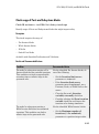
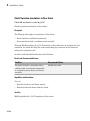
Check safety-related optimization settings . . . . . . . . . . . . . .
Check safety-related diagnostic settings for solvers . . . . . . .
Check safety-related diagnostic settings for sample time . . .
Check safety-related diagnostic settings for signal data . . . .
Check safety-related diagnostic settings for parameters . . .
Check safety-related diagnostic settings for data used for
debugging . . . . . . . . . . . . . . . . . . . . . . . . . . . . . . . . . . . .
3-7
3-8
3-9
3-13
3-16
3-19
3-22
3-24
v
Check safety-related diagnostic settings for data store
memory . . . . . . . . . . . . . . . . . . . . . . . . . . . . . . . . . . . . . .
Check safety-related diagnostic settings for type conversions
Check safety-related diagnostic settings for signal
connectivity . . . . . . . . . . . . . . . . . . . . . . . . . . . . . . . . . . .
Check safety-related diagnostic settings for bus connectivity
Check safety-related diagnostic settings that apply to functioncall connectivity . . . . . . . . . . . . . . . . . . . . . . . . . . . . . . . .
Check safety-related diagnostic settings for compatibility . .
Check safety-related diagnostic settings for model
initialization . . . . . . . . . . . . . . . . . . . . . . . . . . . . . . . . . .
Check safety-related diagnostic settings for model
referencing . . . . . . . . . . . . . . . . . . . . . . . . . . . . . . . . . . .
Check safety-related model referencing settings . . . . . . . . .
Check safety-related code generation settings . . . . . . . . . . .
Check safety-related diagnostic settings for saving . . . . . . .
Check for blocks that do not link to requirements . . . . . . . .
Check state machine type of Stateflow charts . . . . . . . . . . .
Check Stateflow charts for ordering of states and transitions
Check Stateflow debugging options . . . . . . . . . . . . . . . . . . .
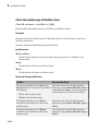
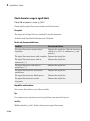
Check usage of lookup table blocks . . . . . . . . . . . . . . . . . . .
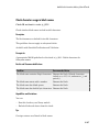
Check MATLAB Code Analyzer messages . . . . . . . . . . . . . .
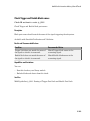
Check MATLAB code for global variables . . . . . . . . . . . . . .
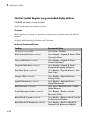
Check for inconsistent vector indexing methods . . . . . . . . .
Check for MATLAB Function interfaces with inherited
properties . . . . . . . . . . . . . . . . . . . . . . . . . . . . . . . . . . . .
Check MATLAB Function metrics . . . . . . . . . . . . . . . . . . . .
Check for blocks not recommended for C/C++ production code
deployment . . . . . . . . . . . . . . . . . . . . . . . . . . . . . . . . . . .
Check Stateflow charts for uniquely defined data objects . . .
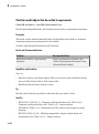
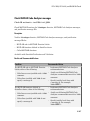
Check usage of Math Operations blocks . . . . . . . . . . . . . . .
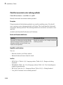
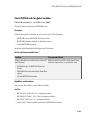
Check usage of Signal Routing blocks . . . . . . . . . . . . . . . . .
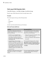
Check usage of Logic and Bit Operations blocks . . . . . . . . .
Check usage of Ports and Subsystems blocks . . . . . . . . . . .
Display model version information . . . . . . . . . . . . . . . . . . .
IEC 61508, ISO 26262, and EN 50128 Checks . . . . . . . . . . . .
IEC 61508, ISO 26262, and EN 50128 Checks . . . . . . . . . . .
Display model metrics and complexity report . . . . . . . . . . .
Check for unconnected objects . . . . . . . . . . . . . . . . . . . . . . .
Check for root Inports with missing properties . . . . . . . . . .
Check for MATLAB Function interfaces with inherited
properties . . . . . . . . . . . . . . . . . . . . . . . . . . . . . . . . . . . .
Check MATLAB Function metrics . . . . . . . . . . . . . . . . . . . .
vi
Contents
3-25
3-27
3-29
3-31
3-33
3-35
3-37
3-40
3-43
3-45
3-51
3-53
3-54
3-56
3-58
3-60
3-62
3-64
3-65
3-66
3-68
3-70
3-71
3-72
3-75
3-76
3-78
3-81
3-82
3-82
3-84
3-86
3-87
3-89
3-91
Check for root Inports with missing range definitions . . . . .
Check for root Outports with missing range definitions . . . .
Check for blocks not recommended for C/C++ production code
deployment . . . . . . . . . . . . . . . . . . . . . . . . . . . . . . . . . . .
Check usage of Stateflow constructs . . . . . . . . . . . . . . . . . .
Check state machine type of Stateflow charts . . . . . . . . . .
Check for model objects that do not link to requirements . .
Check for inconsistent vector indexing methods . . . . . . . . .
Check MATLAB Code Analyzer messages . . . . . . . . . . . . .
Check MATLAB code for global variables . . . . . . . . . . . . .
Check usage of Math Operations blocks . . . . . . . . . . . . . .
Check usage of Signal Routing blocks . . . . . . . . . . . . . . . .
Check usage of Logic and Bit Operations blocks . . . . . . . .
Check usage of Ports and Subsystems blocks . . . . . . . . . . .
Display configuration management data . . . . . . . . . . . . . .
MathWorks Automotive Advisory Board Checks . . . . . . . .
MathWorks Automotive Advisory Board Checks . . . . . . . .
Check font formatting . . . . . . . . . . . . . . . . . . . . . . . . . . . .
Check Transition orientations in flow charts . . . . . . . . . . .
Check for nondefault block attributes . . . . . . . . . . . . . . . .
Check signal line labels . . . . . . . . . . . . . . . . . . . . . . . . . . .
Check for propagated signal labels . . . . . . . . . . . . . . . . . .
Check default transition placement in Stateflow charts . . .
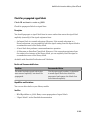
Check return value assignments of graphical functions in
Stateflow charts . . . . . . . . . . . . . . . . . . . . . . . . . . . . . .
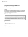
Check entry formatting in State blocks in Stateflow charts
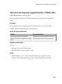
Check usage of return values from a graphical function in
Stateflow charts . . . . . . . . . . . . . . . . . . . . . . . . . . . . . .
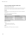
Check for pointers in Stateflow charts . . . . . . . . . . . . . . . .
Check for event broadcasts in Stateflow charts . . . . . . . . .
Check transition actions in Stateflow charts . . . . . . . . . . .
Check for MATLAB expressions in Stateflow charts . . . . .
Check for indexing in blocks . . . . . . . . . . . . . . . . . . . . . . .
Check file names . . . . . . . . . . . . . . . . . . . . . . . . . . . . . . . .
Check folder names . . . . . . . . . . . . . . . . . . . . . . . . . . . . . .
Check for prohibited blocks in discrete controllers . . . . . . .
Check for prohibited sink blocks . . . . . . . . . . . . . . . . . . . .
Check positioning and configuration of ports . . . . . . . . . . .
Check for matching port and signal names . . . . . . . . . . . .
Check whether block names appear below blocks . . . . . . .
Check for mixing basic blocks and subsystems . . . . . . . . .
Check for unconnected ports and signal lines . . . . . . . . . .
Check position of Trigger and Enable blocks . . . . . . . . . . .
3-93
3-95
3-97
3-98
3-102
3-104
3-106
3-107
3-109
3-110
3-112
3-113
3-115
3-118
3-119
3-121
3-122
3-124
3-125
3-127
3-129
3-130
3-131
3-132
3-133
3-134
3-135
3-136
3-137
3-138
3-140
3-141
3-142
3-143
3-144
3-146
3-147
3-148
3-149
3-150
vii
Check usage of tunable parameters in blocks . . . . . . . . . .
Check Stateflow data objects with local scope . . . . . . . . . .
Check for Strong Data Typing with Simulink I/O . . . . . . .
Check usage of exclusive and default states in state
machines . . . . . . . . . . . . . . . . . . . . . . . . . . . . . . . . . . . .
Check Implement logic signals as Boolean data (vs. double)
Check model diagnostic parameters . . . . . . . . . . . . . . . . .
Check the display attributes of block names . . . . . . . . . . .
Check display for port blocks . . . . . . . . . . . . . . . . . . . . . .
Check subsystem names . . . . . . . . . . . . . . . . . . . . . . . . . .
Check port block names . . . . . . . . . . . . . . . . . . . . . . . . . .
Check character usage in signal labels . . . . . . . . . . . . . . .
Check character usage in block names . . . . . . . . . . . . . . .
Check Trigger and Enable block names . . . . . . . . . . . . . . .
Check for Simulink diagrams using nonstandard display
attributes . . . . . . . . . . . . . . . . . . . . . . . . . . . . . . . . . . . .
Check MATLAB code for global variables . . . . . . . . . . . . .
Check visibility of block port names . . . . . . . . . . . . . . . . .
Check orientation of Subsystem blocks . . . . . . . . . . . . . . .
Check usage of Relational Operator blocks . . . . . . . . . . . .
Check usage of Switch blocks . . . . . . . . . . . . . . . . . . . . . .
Check usage of buses and Mux blocks . . . . . . . . . . . . . . . .
Check for bitwise operations in Stateflow charts . . . . . . . .
Check for comparison operations in Stateflow charts . . . . .
Check for unary minus operations on unsigned integers in
Stateflow charts . . . . . . . . . . . . . . . . . . . . . . . . . . . . . .
Check for equality operations between floating-point
expressions in Stateflow charts . . . . . . . . . . . . . . . . . . .
Check input and output settings of MATLAB Functions . .
Check MATLAB Function metrics . . . . . . . . . . . . . . . . . . .
Check for mismatches between names of Stateflow ports and
associated signals . . . . . . . . . . . . . . . . . . . . . . . . . . . . .
Check scope of From and Goto blocks . . . . . . . . . . . . . . . .
Requirements Consistency Checks . . . . . . . . . . . . . . . . . . .
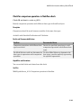
Identify requirement links with missing documents . . . . .
Identify requirement links that specify invalid locations within
documents . . . . . . . . . . . . . . . . . . . . . . . . . . . . . . . . . . .
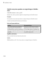
Identify selection-based links having descriptions that do not
match their requirements document text . . . . . . . . . . . .
Identify requirement links with path type inconsistent with
preferences . . . . . . . . . . . . . . . . . . . . . . . . . . . . . . . . . .
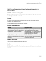
Identify IBM Rational DOORS objects linked from Simulink
that do not link to Simulink . . . . . . . . . . . . . . . . . . . . .
viii
Contents
3-151
3-152
3-153
3-154
3-156
3-157
3-160
3-162
3-163
3-165
3-166
3-167
3-169
3-170
3-172
3-173
3-175
3-176
3-177
3-178
3-179
3-181
3-182
3-183
3-184
3-186
3-188
3-189
3-190
3-191
3-192
3-193
3-195
3-197
1
Functions — Alphabetical List
1
Functions — Alphabetical List
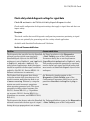
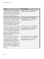
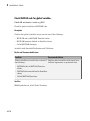
actionCallback
Class: Advisor.authoring.CustomCheck
Package: Advisor.authoring
Register action callback for model configuration check
Syntax
Advisor.authoring.CustomCheck.actionCallback(task)
Description
Advisor.authoring.CustomCheck.actionCallback(task) is used as the action
callback function when registering custom checks that use an XML data file to specify
check behavior.
Examples
This sl_customization.m file registers the action callback for configuration parameter
checks with fix actions.
function defineModelAdvisorChecks
rec = ModelAdvisor.Check('com.mathworks.Check1');
rec.Title = 'Test: Check1';
rec.setCallbackFcn(@(system)(Advisor.authoring.CustomCheck.checkCallback(system)), …
'None', 'StyleOne');
rec.TitleTips = 'Example check for check authoring infrastructure.';
% --- data file input parameters
rec.setInputParametersLayoutGrid([1 1]);
inputParam1 = ModelAdvisor.InputParameter;
inputParam1.Name = 'Data File';
inputParam1.Value = 'Check1.xml';
inputParam1.Type = 'String';
inputParam1.Description = 'Name or full path of XML data file.';
inputParam1.setRowSpan([1 1]);
inputParam1.setColSpan([1 1]);
rec.setInputParameters({inputParam1});
% -- set fix operation
1-2
actionCallback
act = ModelAdvisor.Action;
act.setCallbackFcn(@(task)(Advisor.authoring.CustomCheck.actionCallback(task)));
act.Name = 'Modify Settings';
act.Description = 'Modify model configuration settings.';
rec.setAction(act);
mdladvRoot = ModelAdvisor.Root;
mdladvRoot.register(rec);
end
See Also
Advisor.authoring.DataFile |
Advisor.authoring.CustomCheck.checkCallback |
Advisor.authoring.generateConfigurationParameterDataFile
How To
•
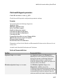
“Create Check for Model Configuration Parameters”
1-3
1
Functions — Alphabetical List
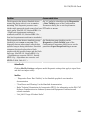
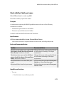
addCheck
Class: ModelAdvisor.FactoryGroup
Package: ModelAdvisor
Add check to folder
Syntax
addCheck(fg_obj, check_ID)
Description
addCheck(fg_obj, check_ID) adds checks, identified by check_ID, to the folder
specified by fg_obj, which is an instantiation of the ModelAdvisor.FactoryGroup
class.
Examples
Add three checks to rec:
% --- sample factory group
rec = ModelAdvisor.FactoryGroup('com.mathworks.sample.factorygroup');
.
.
.
addCheck(rec, 'com.mathworks.sample.Check1');
addCheck(rec, 'com.mathworks.sample.Check2');
addCheck(rec, 'com.mathworks.sample.Check3');
1-4
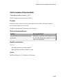
addGroup
addGroup
Class: ModelAdvisor.Group
Package: ModelAdvisor
Add subfolder to folder
Syntax
addGroup(group_obj, child_obj)
Description
addGroup(group_obj, child_obj) adds a new subfolder, identified by
child_obj, to the folder specified by group_obj, which is an instantiation of the
ModelAdvisor.Group class.
Examples
Add three checks to rec:
group_obj = ModelAdvisor.Group('com.mathworks.sample.group');
.
.
.
addGroup(group_obj, 'com.mathworks.sample.subgroup1');
addGroup(group_obj, 'com.mathworks.sample.subgroup2');
addGroup(group_obj, 'com.mathworks.sample.subgroup3');
To add ModelAdvisor.Task objects to a group using addGroup:
mdladvRoot = ModelAdvisor.Root();
% MAT1, MAT2, and MAT3 are registered ModelAdvisor.Task objects
% Create the group 'My Group'
MAG = ModelAdvisor.Group('com.mathworks.sample.GroupSample');
MAG.DisplayName='My Group';
1-5
1
Functions — Alphabetical List
% Add the first task to the 'My Group' folder
MAG.addTask(MAT1);
% Create a subfolder 'Folder1'
MAGSUB1 = ModelAdvisor.Group('com.mathworks.sample.Folder1');
MAGSUB1.DisplayName='Folder1';
% Add the second task to Folder1
MAGSUB1.addTask(MAT2);
% Create a subfolder 'Folder2'
MAGSUB2 = ModelAdvisor.Group('com.mathworks.sample.Folder2');
MAGSUB2.DisplayName='Folder2';
% Add the third task to Folder2
MAGSUB2.addTask(MAT3);
% Register the two subfolders. This must be done before calling addGroup
mdladvRoot.register(MAGSUB1);
mdladvRoot.register(MAGSUB2);
% Invoke addGroup to place the subfolders under 'My Group'
MAG.addGroup(MAGSUB1);
MAG.addGroup(MAGSUB2);
mdladvRoot.publish(MAG); % publish under Root
1-6
addItem
addItem
Class: ModelAdvisor.List
Package: ModelAdvisor
Add item to list
Syntax
addItem(element)
Description
addItem(element) adds items to the list created by the ModelAdvisor.List
constructor.
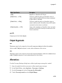
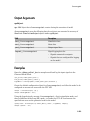
Input Arguments
element
Specifies an element to be added to a list in one of the following:
• Element
• Cell array of elements. When you add a cell array to a list,
they form different rows in the list.
• String
Examples
subList = ModelAdvisor.List();
setType(subList, 'numbered')
addItem(subList, ModelAdvisor.Text('Sub entry 1', {'pass','bold'}));
addItem(subList, ModelAdvisor.Text('Sub entry 2', {'pass','bold'}));
See Also
“Model Advisor Customization”
1-7
1
Functions — Alphabetical List
How To
•
1-8
“Create Model Advisor Checks”
addItem
addItem
Class: ModelAdvisor.Paragraph
Package: ModelAdvisor
Add item to paragraph
Syntax
addItem(text, element)
Description
addItem(text, element) adds an element to text. element is one of the following:
• String
• Element
• Cell array of elements
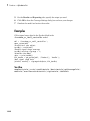
Examples
Add two lines of text:
result = ModelAdvisor.Paragraph;
addItem(result, [resultText1 ModelAdvisor.LineBreak resultText2]);
See Also
“Model Advisor Customization”
How To
•
“Create Model Advisor Checks”
1-9
1
Functions — Alphabetical List
addProcedure
Class: ModelAdvisor.Group
Package: ModelAdvisor
Add procedure to folder
Syntax
addProcedure(group_obj, procedure_obj)
Description
addProcedure(group_obj, procedure_obj) adds a procedure, specified by
procedure_obj, to the folder group_obj. group_obj is an instantiation of the
ModelAdvisor.Group class.
Examples
Add three procedures to MAG.
MAG = ModelAdvisor.Group('com.mathworks.sample.GroupSample');
MAP1=ModelAdvisor.Procedure('com.mathworks.sample.procedure1');
MAP2=ModelAdvisor.Procedure('com.mathworks.sample.procedure2');
MAP3=ModelAdvisor.Procedure('com.mathworks.sample.procedure3');
addProcedure(MAG, MAP1);
addProcedure(MAG, MAP2);
addProcedure(MAG, MAP3);
1-10
addProcedure
addProcedure
Class: ModelAdvisor.Procedure
Package: ModelAdvisor
Add subprocedure to procedure
Syntax
addProcedure(procedure1_obj, procedure2_obj)
Description
addProcedure(procedure1_obj, procedure2_obj) adds a procedure, specified
by procedure2_obj, to the procedure procedure1_obj. procedure2_obj and
procedure1_obj are instantiations of the ModelAdvisor.Procedure class.
Examples
Add three procedures to MAP.
MAP = ModelAdvisor.Procedure('com.mathworks.sample.ProcedureSample');
MAP1=ModelAdvisor.Procedure('com.mathworks.sample.procedure1');
MAP2=ModelAdvisor.Procedure('com.mathworks.sample.procedure2');
MAP3=ModelAdvisor.Procedure('com.mathworks.sample.procedure3');
addProcedure(MAP, MAP1);
addProcedure(MAP, MAP2);
addProcedure(MAP, MAP3);
1-11
1
Functions — Alphabetical List
addRow
Class: ModelAdvisor.FormatTemplate
Package: ModelAdvisor
Add row to table
Syntax
addRow(ft_obj, {item1, item2, ..., itemn})
Description
addRow(ft_obj, {item1, item2, ..., itemn}) is an optional method that
adds a row to the end of a table in the result. ft_obj is a handle to the template object
previously created. {item1, item2, ..., itemn} is a cell array of strings and objects
to add to the table. The order of the items in the array determines which column the item
is in. If you do not add data to the table, the Model Advisor does not display the table in
the result.
Note: Before adding rows to a table, you must specify column titles using the
setColTitle method.
Examples
Find all of the blocks in the model and create a table of the blocks:
% Create FormatTemplate object, specify table format
ft = ModelAdvisor.FormatTemplate('TableTemplate');
% Add information to the table
setTableTitle(ft, {'Blocks in Model'});
setColTitles(ft, {'Index', 'Block Name'});
% Find all the blocks in the system and add them to a table.
allBlocks = find_system(system);
for inx = 2 : length(allBlocks)
% Add information to the table
addRow(ft, {inx-1,allBlocks(inx)});
1-12
addRow
end
See Also
“Model Advisor Customization”
How To
•
“Create Model Advisor Checks”
•
“Format Model Advisor Results”
1-13
1
Functions — Alphabetical List
addTask
Class: ModelAdvisor.Group
Package: ModelAdvisor
Add task to folder
Syntax
addTask(group_obj, task_obj)
Description
addTask(group_obj, task_obj) adds a task, specified by task_obj, to the folder
group_obj.group_obj is an instantiation of the ModelAdvisor.Group class.
Examples
Add three tasks to MAG.
MAG = ModelAdvisor.Group('com.mathworks.sample.GroupSample');
addTask(MAG, MAT1);
addTask(MAG, MAT2);
addTask(MAG, MAT3);
1-14
addTask
addTask
Class: ModelAdvisor.Procedure
Package: ModelAdvisor
Add task to procedure
Syntax
addTask(procedure_obj, task_obj)
Description
addTask(procedure_obj, task_obj) adds a task, specified by task_obj, to
procedure_obj.procedure_obj is an instantiation of the ModelAdvisor.Procedure
class.
Examples
Add three tasks to MAP.
MAP = ModelAdvisor.Procedure('com.mathworks.sample.ProcedureSample');
MAT1=ModelAdvisor.Task('com.mathworks.sample.task1');
MAT2=ModelAdvisor.Task('com.mathworks.sample.task2');
MAT3=ModelAdvisor.Task('com.mathworks.sample.task3');
addTask(MAP, MAT1);
addTask(MAP, MAT2);
addTask(MAP, MAT3);
1-15
1
Functions — Alphabetical List
Advisor.authoring.generateConfigurationParameterDataFile
Package: Advisor.authoring
Generate XML data file for custom configuration parameter check
Syntax
Advisor.authoring.generateConfigurationParameterDataFile(dataFile,
source)
Advisor.authoring.generateConfigurationParameterDataFile(dataFile,
source,Name,Value)
Description
Advisor.authoring.generateConfigurationParameterDataFile(dataFile,
source) generates an XML data file named dataFile specifying the configuration
parameters for source. The data file uses tagging to specify the configuration parameter
settings you want. When you create a check for configuration parameters, you use the
data file. Each model configuration parameter specified in the data file is a subcheck.
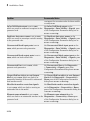
Advisor.authoring.generateConfigurationParameterDataFile(dataFile,
source,Name,Value) generates an XML data file named dataFile specifying the
configuration parameters for source. It also specifies additional options by one or more
optional Name,Value arguments. The data file uses tagging to specify the configuration
parameter settings you want. When you create a check for configuration parameters,
you use the data file. Each model configuration parameter specified in the data file is a
subcheck.
Examples
Create data file for configuration parameter check
Create a data file with all the configuration parameters. You use the data file to create a
configuration parameter.
1-16
Advisor.authoring.generateConfigurationParameterDataFile
model = 'vdp';
dataFile = 'myDataFile.xml';
Advisor.authoring.generateConfigurationParameterDataFile( ...
dataFile, model);
Data file myDataFile.xml has tagging specifying subcheck information for each
configuration parameter. myDataFile.xml specifies the configuration parameters
settings you want. The following specifies XML tagging for configuration parameter
AbsTol. If the configuration parameter is set to 1e-6, the configuration parameter
subcheck specified in myDataFile.xml passes.
<!-- Absolute tolerance: (AbsTol)-->
<PositiveModelParameterConstraint>
<parameter>AbsTol</parameter>
<value>1e-6</value>
</PositiveModelParameterConstraint>
Create data file for Solver pane configuration parameter check with fix action
Create a data file with configuration parameters for the Solver pane. You use the data
file to create a Solver pane configuration parameter check with fix actions.
model = 'vdp';
dataFile = 'myDataFile.xml';
Advisor.authoring.generateConfigurationParameterDataFile( ...
dataFile, model, 'Pane', 'Solver', 'FixValues', true);
Data file myDataFile.xml has tagging specifying subcheck information for each
configuration parameter. myDataFile.xml specifies the configuration parameters
settings that you want. The following specifies XML tagging for configuration parameter
AbsTol. If the configuration parameter is set to 1e-6, the configuration parameter
subcheck specified in myDataFile.xml passes. If the subcheck does not pass, the check
fix action modifies the configuration parameter to 1e-6.
<!-- Absolute tolerance: (AbsTol)-->
<PositiveModelParameterConstraint>
<parameter>AbsTol</parameter>
<value>1e-6</value>
<fixvalue>1e-6</fixvalue>
</PositiveModelParameterConstraint>
•
“Create Check for Model Configuration Parameters”
1-17
1
Functions — Alphabetical List
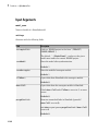
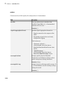
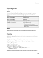
Input Arguments
dataFile — Name of data file to create
string
Name of XML data file to create, specified as a string.
Example: 'myDataFile.xml'
source — Name of model or configuration set
string | Simulink.ConfigSet
Name of model or Simulink.ConfigSet object used to specify configuration parameters
Example: 'vdp'
Name-Value Pair Arguments
Specify optional comma-separated pairs of Name,Value arguments. Name is the
argument name and Value is the corresponding value. Name must appear inside single
quotes (' '). You can specify several name and value pair arguments in any order as
Name1,Value1,...,NameN,ValueN.
Example: 'Pane', 'Solver', 'FixValues', true specifies a dataFile with Solver
pane configuration parameters and fix tagging.
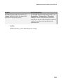
'Pane' — Limit the configuration parameters in the dataFile
Solver | Data Import/Export | Optimization | Diagnostics | Hardware
Implementation | Model Referencing | Code Generation
Option to limit the configuration parameters in the data file to the pane specified as the
comma-separated pair of 'Pane' and one of the following:
• Solver
• Data Import/Export
• Optimization
• Diagnostics
• Hardware Implementation
• Model Referencing
• Code Generation
1-18
Advisor.authoring.generateConfigurationParameterDataFile
Example: 'Pane','Solver' limits the dataFile to configuration parameters on the
Solver pane.
Data Types: char
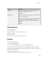
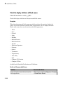
'FixValues' — Create fix tagging in the dataFile
false | true
Setting FixValues to true provides the dataFile with fix tagging. When you generate
a custom configuration parameter check using a dataFile with fix tagging, each
configuration parameter subcheck has a fix action. Specified as the comma-separated
pair of 'FixValues' and either true or false.
Example: 'FixValues,true specifies fix tagging in the dataFile.
Data Types: logical
More About
•
“Data File for Configuration Parameter Check”
1-19
1
Functions — Alphabetical List
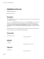
Advisor.authoring.CustomCheck class
Package: Advisor.authoring
Define custom check
Description
Instances of the Advisor.authoring.CustomCheck class provide a container for static
methods used as callback functions when defining a configuration parameter check. The
configuration parameter check is defined in an XML data file.
Methods
actionCallback
Register action callback for model
configuration check
checkCallback
Register check callback for model
configuration check
Copy Semantics
Handle. To learn how this affects your use of the class, see Copying Objects in the
MATLAB® Programming Fundamentals documentation.
See Also
Advisor.authoring.DataFile |
Advisor.authoring.generateConfigurationParameterDataFile
How To
•
1-20
“Create Check for Model Configuration Parameters”
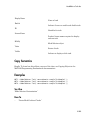
Advisor.authoring.DataFile class
Advisor.authoring.DataFile class
Package: Advisor.authoring
Interact with data file for model configuration checks
Description
The Advisor.authoring.DataFile class provides a container for a static method used
when interacting with the data file for configuration parameter checks.
Methods
validate
Validate XML data file used for model
configuration check
Copy Semantics
Handle. To learn how this affects your use of the class, see Copying Objects in the
MATLAB Programming Fundamentals documentation.
See Also
Advisor.authoring.CustomCheck |
Advisor.authoring.generateConfigurationParameterDataFile
How To
•
“Create Check for Model Configuration Parameters”
1-21
1
Functions — Alphabetical List
allNames
Class: cv.cvdatagroup
Package: cv
Get names of all models associated with cvdata objects in cv.cvdatagroup
Syntax
models = allNames(cvdg)
Description
models = allNames(cvdg) returns a cell array of strings identifying all model names
associated with the cvdata objects in cvdg, an instantiation of the cv.cvdatagroup
class.
Examples
Add three cvdata objects to cvdg and return a cell array of model names:
a = cvdata;
b = cvdata;
c = cvdata;
cvdg = cv.cvdatagroup;
add (cvdg, a, b, c);
model_names = allNames(cvdg)
1-22
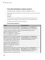
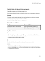
checkCallback
checkCallback
Class: Advisor.authoring.CustomCheck
Package: Advisor.authoring
Register check callback for model configuration check
Syntax
Advisor.authoring.CustomCheck.checkCallback(system)
Description
Advisor.authoring.CustomCheck.checkCallback(system) is used as the check
callback function when registering custom checks that use an XML data file to specify
check behavior.
Examples
This sl_customization.m file registers a configuration parameter check using
Advisor.authoring.CustomCheck.checkCallback(system).
function defineModelAdvisorChecks
rec = ModelAdvisor.Check('com.mathworks.Check1');
rec.Title = 'Test: Check1';
rec.setCallbackFcn(@(system)(Advisor.authoring.CustomCheck.checkCallback(system)), …
'None', 'StyleOne');
rec.TitleTips = 'Example check for check authoring infrastructure.';
% --- data file input parameters
rec.setInputParametersLayoutGrid([1 1]);
inputParam1 = ModelAdvisor.InputParameter;
inputParam1.Name = 'Data File';
inputParam1.Value = 'Check1.xml';
inputParam1.Type = 'String';
inputParam1.Description = 'Name or full path of XML data file.';
inputParam1.setRowSpan([1 1]);
inputParam1.setColSpan([1 1]);
rec.setInputParameters({inputParam1});
% -- set fix operation
1-23
1
Functions — Alphabetical List
act = ModelAdvisor.Action;
act.setCallbackFcn(@(task)(Advisor.authoring.CustomCheck.actionCallback(task)));
act.Name = 'Modify Settings';
act.Description = 'Modify model configuration settings.';
rec.setAction(act);
mdladvRoot = ModelAdvisor.Root;
mdladvRoot.register(rec);
end
See Also
Advisor.authoring.DataFile |
Advisor.authoring.CustomCheck.actionCallback |
Advisor.authoring.generateConfigurationParameterDataFile
How To
•
1-24
“Create Check for Model Configuration Parameters”
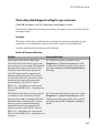
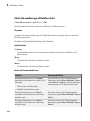
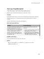
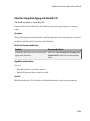
complexityinfo
complexityinfo
Retrieve cyclomatic complexity coverage information from cvdata object
Syntax
complexity = complexityinfo(cvdo, object)
Description
complexity = complexityinfo(cvdo, object) returns complexity coverage
results from the cvdata object cvdo for the model component object.
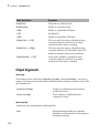
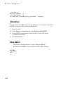
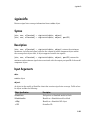
Input Arguments
cvdo
cvdata object
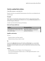
object
The object argument specifies an object in the model or Stateflow® chart that received
decision coverage. Valid values for object include the following:
Object Specification
Description
BlockPath
Full path to a model or block
BlockHandle
Handle to a model or block
slObj
Handle to a Simulink® API object
sfID
Stateflow ID
sfObj
Handle to a Stateflow API object from a singly
instantiated Stateflow chart
{BlockPath, sfID}
Cell array with the path to a Stateflow chart or
atomic subchart and the ID of an object contained
in that chart or subchart
1-25
1
Functions — Alphabetical List
Object Specification
Description
{BlockPath, sfObj}
Cell array with the path to a Stateflow chart
or subchart and a Stateflow object API handle
contained in that chart or subchart
[BlockHandle, sfID]
Array with a handle to a Stateflow chart or
atomic subchart and the ID of an object contained
in that chart or subchart
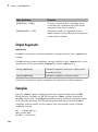
Output Arguments
complexity
If cvdo does not contain cyclomatic complexity coverage results for object, complexity
is empty.
If cvdo contains cyclomatic complexity coverage results for object, complexity is a twoelement vector of the form [total_complexity local_complexity]:
total_complexity
Cyclomatic complexity coverage for object and its
descendants (if any)
local_complexity
Cyclomatic complexity coverage for object
If object has variable-size signals, complexity also contains the variable complexity.
Examples
Open the sldemo_fuelsys model and create the test specification object testObj.
Enable decision, condition, and MCDC coverage for sldemo_fuelsys and execute
testObj using cvsim. Use complexityinfo to retrieve cyclomatic complexity results
for the Throttle subsystem. The Throttle subsystem itself does not record cyclomatic
complexity coverage results, but the contents of the subsystem do record cyclomatic
complexity coverage.
mdl = 'sldemo_fuelsys';
open_system(mdl);
testObj = cvtest(mdl)
1-26
complexityinfo
testObj.settings.decision = 1;
testObj.settings.condition = 1;
testObj.settings.mcdc = 1;
data = cvsim(testObj);
blk_handle = get_param([mdl, ...
'/Engine Gas Dynamics/Throttle & Manifold/Throttle'],...
'Handle');
coverage = complexityinfo(data, blk_handle);
coverage
Alternatives
Use the Coverage Settings dialog box to collect and display cyclomatic complexity
coverage results in the coverage report:
1
Open the model.
2
In the Model Editor, select Analysis > Coverage > Settings.
3
On the Coverage tab, select Coverage for this model.
4
Under Coverage metrics, select:
• Decision
• Condition
• MCDC
5
On the Reporting tab, click HTML Settings.
6
In the HTML Settings dialog box, select:
• Include cyclomatic complexity numbers in summary
• Include cyclomatic complexity numbers in block details
7
Click OK to close the HTML Settings dialog box and save your changes.
8
Click OK to close the Coverage Settings dialog box and save your changes.
9
Simulate the model and review the results in the HTML report.
More About
•
“Cyclomatic Complexity”
1-27
1
Functions — Alphabetical List
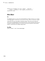
See Also
conditioninfo | cvsim | decisioninfo | getCoverageInfo | mcdcinfo |
sigrangeinfo | sigsizeinfo | tableinfo
1-28
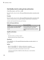
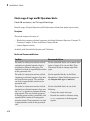
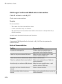
conditioninfo
conditioninfo
Retrieve condition coverage information from cvdata object
Syntax
coverage = conditioninfo(cvdo, object)
coverage = conditioninfo(cvdo, object, ignore_descendants)
[coverage, description] = conditioninfo(cvdo, object)
Description
coverage = conditioninfo(cvdo, object) returns condition coverage results from
the cvdata object cvdo for the model component specified by object.
coverage = conditioninfo(cvdo, object, ignore_descendants) returns
condition coverage results for object, depending on the value of ignore_descendants.
[coverage, description] = conditioninfo(cvdo, object) returns condition
coverage results and textual descriptions of each condition in object.
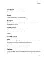
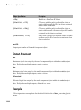
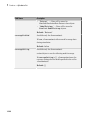
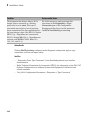
Input Arguments
cvdo
cvdata object
object
An object in the Simulink model or Stateflow diagram that receives decision coverage.
Valid values for object are as follows:
BlockPath
Full path to a Simulink model or block
BlockHandle
Handle to a Simulink model or block
slObj
Handle to a Simulink API object
sfID
Stateflow ID
1-29
1
Functions — Alphabetical List
sfObj
Handle to a Stateflow API object
{BlockPath, sfID}
Cell array with the path to a Stateflow
chart or atomic subchart and the ID of an
object contained in that chart or subchart
{BlockPath, sfObj}
Cell array with the path to a Stateflow
chart or atomic subchart and a Stateflow
object API handle contained in that chart
or subchart
[BlockHandle, sfID]
Array with a handle to a Stateflow chart
or atomic subchart and the ID of an object
contained in that chart or subchart
ignore_descendants
Logical value that specifies whether to ignore the coverage of descendant objects
1 to ignore coverage of descendant objects
0 (default) to collect coverage of descendant objects
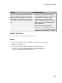
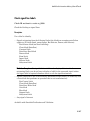
Output Arguments
coverage
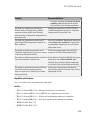
The value of coverage is a two-element vector of form [covered_outcomes
total_outcomes]. coverage is empty if cvdo does not contain condition coverage
results for object. The two elements are:
covered_outcomes
Number of condition outcomes satisfied for
object
total_outcomes
Total number of condition outcomes for
object
description
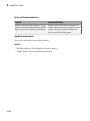
A structure array with the following fields:
text
1-30
String describing a condition or the block
port to which it applies
conditioninfo
trueCnts
Number of times the condition was true in
a simulation
falseCnts
Number of times the condition was false in
a simulation
Examples
The following example opens the slvnvdemo_cv_small_controller example model,
creates the test specification object testObj, enables condition coverage for testObj,
and executes testObj. Then retrieve the condition coverage results for the Logic block
(in the Gain subsystem) and determine its percentage of condition outcomes covered:
mdl = 'slvnvdemo_cv_small_controller';
open_system(mdl)
testObj = cvtest(mdl)
testObj.settings.condition = 1;
data = cvsim(testObj)
blk_handle = get_param([mdl, '/Gain/Logic'], 'Handle');
cov = conditioninfo(data, blk_handle)
percent_cov = 100 * cov(1) / cov(2)
Alternatives
Use the Coverage Settings dialog box to collect condition coverage for a model:
1
Open the model for which you want to collect condition coverage.
2
In the Model Editor, select Analysis > Coverage > Settings.
3
On the Coverage tab, select Coverage for this model.
4
Under Coverage metrics, select Condition.
5
On the Results and Reporting tabs, specify the output you need.
6
Click OK to close the Coverage Settings dialog box and save your changes.
7
Simulate the model and review the results.
More About
•
“Condition Coverage (CC)”
1-31
1
Functions — Alphabetical List
See Also
complexityinfo | cvsim | decisioninfo | getCoverageInfo | mcdcinfo |
overflowsaturationinfo | sigrangeinfo | sigsizeinfo | tableinfo
1-32
cv.cvdatagroup class
cv.cvdatagroup class
Package: cv
Collection of cvdata objects
Description
Instances of this class contain a collection of cvdata objects. Each cvdata object
contains coverage results for a particular model in the model hierarchy.
Construction
cv.cvdatagroup
Create collection of cvdata objects for
model reference hierarchy
Methods
allNames
Get names of all models associated with
cvdata objects in cv.cvdatagroup
get
Get cvdata object
getAll
Get all cvdata objects
Properties
name
cv.cvdatagroup object name
1-33
1
Functions — Alphabetical List
Copy Semantics
Handle. To learn how this affects your use of the class, see Copying Objects in the
MATLAB Programming Fundamentals documentation.
1-34
cv.cvdatagroup
cv.cvdatagroup
Class: cv.cvdatagroup
Package: cv
Create collection of cvdata objects for model reference hierarchy
Syntax
cvdg = cv.cvdatagroup(cvdo1, cvdo2,...)
Description
cvdg = cv.cvdatagroup(cvdo1, cvdo2,...) creates an instantiation of the
cv.cvdatagroup class (cvdg) that contains the cvdata objects cvdo1, cvdo2, etc. A
cvdata object contains results of the simulation runs.
Examples
Create an instantiation of the cv.cvdatagroup class and add two cvdata objects to it:
a = cvdata;
b = cvdata;
cvdg = cv.cvdatagroup(a, b);
1-35
1
Functions — Alphabetical List
cvexit
Exit model coverage environment
Syntax
cvexit
Description
cvexit exits the model coverage environment. Issuing this command closes the
Coverage Display window and removes coloring from a block diagram that displays its
model coverage results.
1-36
cvhtml
cvhtml
Produce HTML report from model coverage objects
Syntax
cvhtml(file,
cvhtml(file,
cvhtml(file,
cvhtml(file,
cvdo)
cvdo1, cvdo2, ...)
cvdo1, cvdo2, ..., options)
cvdo1, cvdo2, ..., options, detail)
Description
cvhtml(file, cvdo) creates an HTML report of the coverage results in the cvdata
or cv.cvdatagroup object cvdo when you run model coverage in simulation. cvhtml
saves the coverage results in file. The model must be open when you use cvhtml to
generate its coverage report.
cvhtml(file, cvdo1, cvdo2, ...) creates a combined report of several cvdata
objects. The results from each object appear in a separate column of the HTML report.
Each cvdata object must correspond to the same root model or subsystem. Otherwise,
the function fails.
cvhtml(file, cvdo1, cvdo2, ..., options) creates a combined report of several
cvdata objects using the report options specified by options.
cvhtml(file, cvdo1, cvdo2, ..., options, detail) creates a combined
coverage report for several cvdata objects and specifies the detail level of the report with
the value of detail.
Input Arguments
cvdo
A cv.cvdatagroup object
1-37
1
Functions — Alphabetical List
detail
Specifies the level of detail in the report. Set detail to an integer from 0 to 3. Greater
numbers for detail indicate greater detail.
Default: 2
file
String specifying the HTML file in the MATLAB current folder where cvhtml stores the
results
Default: []
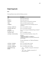
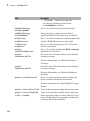
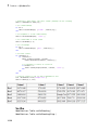
options
Specify the report options that you specify in options:
• To enable an option, set it to 1 (e.g., '-hTR=1').
• To disable an option, set it to 0 (e.g., '-bRG=0').
• To specify multiple report options, list individual options in a single options string
separated by commas or spaces (e.g., '-hTR=1 -bRG=0 -scm=0').
1-38
Option
Description
Default
-sRT
Show report
on
-sVT
Web view mode
off
-aTS
Include each test in the model summary
on
-bRG
Produce bar graphs in the model summary
on
-bTC
Use two color bar graphs (red, blue)
on
-hTR
Display hit/count ratio in the model summary
off
-nFC
Do not report fully covered model objects
off
-scm
Include cyclomatic complexity numbers in summary
on
-bcm
Include cyclomatic complexity numbers in block
details
on
-xEv
Filter Stateflow events from report
off
cvhtml
Examples
Make sure you have write access to the default MATLAB folder. Create a cumulative
coverage report for the slvnvdemo_cv_small_controller mode and save it as
ratelim_coverage.html:
model = 'slvnvdemo_cv_small_controller';
open_system(model);
cvt = cvtest(model);
cvd = cvsim(cvt);
outfile = 'ratelim_coverage.html';
cvhtml(outfile, cvd);
Alternatives
Use the Coverage Settings dialog box to create a model coverage report in an HTML file:
1
Open the model for which you want a model coverage report.
2
In the Simulink Editor, select Analysis > Coverage > Settings.
3
On the Coverage tab, select Coverage for this model.
4
On the Report tab, select Generate HTML report.
5
Click OK to close the Coverage Settings dialog box and save your changes.
6
Simulate the model and review the generated report.
More About
•
“Create HTML Reports with cvhtml”
See Also
cv.cvdatagroup | cvsim | cvmodelview
1-39
1
Functions — Alphabetical List
cvload
Load coverage tests and stored results into memory
Syntax
[tests, data] = cvload(filename)
[tests, data] = cvload(filename, restoretotal)
Description
[tests, data] = cvload(filename) loads the tests and data stored in the text
file filename.cvt. tests is a cell array of cvtest objects that are loaded. data is a
cell array of cvdata objects that are loaded. data has the same size as tests, but if a
particular test has no results, data can contain empty elements.
[tests, data] = cvload(filename, restoretotal) restores or clears the
cumulative results from prior runs, depending on the value of restoretotal. If
restoretotal is 1, cvload restores the cumulative results from prior runs. If
restoretotal is unspecified or 0, cvload clears the model's cumulative results.
The following are special considerations for using the cvload command:
• If a model with the same name exists in the coverage database, the software loads
only the compatible results that reference the existing model to prevent duplication.
• If the Simulink models referenced from the file are open but do not exist in the
coverage database, the coverage tool resolves the links to the existing models.
• When you are loading several files that reference the same model, the software loads
only the results that are consistent with the earlier files.
Examples
Store coverage results in cvtest and cvdata objects:
[test_objects, data_objects] = cvload(test_results, 1);
1-40
cvload
More About
•
“Load Stored Coverage Test Results with cvload”
See Also
cvsave
1-41
1
Functions — Alphabetical List
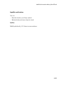
cvmodelview
Display model coverage results with model coloring
Syntax
cvmodelview(cvdo)
Description
cvmodelview(cvdo) displays coverage results from the cvdata object cvdo by coloring
the objects in the model that have model coverage results.
Examples
Open the slvnvdemo_cv_small_controller example model, create the test
specification object testObj, and execute testObj to collect model coverage.
Run cvmodelview to color the model objects for which you collect model coverage
information:
mdl = 'slvnvdemo_cv_small_controller';
open_system(mdl)
testObj = cvtest(mdl)
data = cvsim(testObj)
cvmodelview(data)
Alternatives
Use the Coverage Settings dialog box to display model coverage results by coloring
objects:
1-42
1
Open the model.
2
Select Analysis > Coverage > Settings.
3
On the Coverage tab, select Coverage for this model.
cvmodelview
4
On the Results tab, select Display coverage results using model coloring.
5
Click OK to close the Coverage Settings dialog box and save your changes.
6
Simulate the model and review the results.
More About
•
“View Coverage Results in a Model”
See Also
cvhtml | cvsim
1-43
1
Functions — Alphabetical List
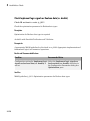
cvsave
Save coverage tests and results to file
Syntax
cvsave(filename, model)
cvsave(filename, cvto1, cvto2, ...)
cvsave(filename, cell_array{ :})
Description
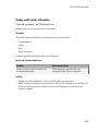
cvsave(filename, model) saves all the tests (cvtest objects) and results (cvdata
objects) related to model in the text file filename.cvt. model is a handle to or name of
a Simulink model.
cvsave(filename, cvto1, cvto2, ...) saves multiple cvtest objects in the text
file filename.cvt. cvsave also saves information about any referenced models.
cvsave(filename, cell_array{ :}) saves the test results stored in each element
of cell_array to the file filename.cvt. Each element in cell_array contains test
results for a cvdata object.
Input Arguments
filename
String containing the name of the file in which to save the data. cvsave appends the
extension .cvt to the string when saving the file.
model
Handle to a Simulink model
cvto
cvtest object
1-44
cvsave
cell_array
Cell array of cvtest objects
Examples
Save coverage results for the slvnvdemo_cv_small_controller model in
ratelim_testdata.cvt:
model = 'slvnvdemo_cv_small_controller';
open_system(model);
cvt = cvtest(model);
cvd = cvsim(cvt);
cvsave('ratelim_testdata', model);
Save cumulative coverage results for the Adjustable Rate Limiter subsystem in the
slvnvdemo_ratelim_harness model from two simulations:
% Open model and subsystem
mdl = 'slvnvdemo_ratelim_harness';
mdl_subsys = ...
'slvnvdemo_ratelim_harness/Adjustable Rate Limiter';
open_system(mdl);
open_system(mdl_subsys);
% Create data files
t_gain = (0:0.02:2.0)';
u_gain = sin(2*pi*t_gain);
t_pos = [0;2];
u_pos = [1;1];
t_neg = [0;2];
u_neg = [-1;-1];
save('within_lim.mat','t_gain','u_gain','t_pos','u_pos', ...
't_neg', 'u_neg');
t_gain = [0;2];
u_gain = [0;4];
t_pos = [0;1;1;2];
u_pos = [1;1;5;5]*0.02;
t_neg = [0;2];
u_neg = [0;0];
save('rising_gain.mat','t_gain','u_gain','t_pos','u_pos', ...
't_neg', 'u_neg');
1-45
1
Functions — Alphabetical List
% Specify coverage options in cvtest object
testObj1 = cvtest(mdl_subsys);
testObj1.label = 'Gain within slew limits';
testObj1.setupCmd = 'load(''within_lim.mat'');';
testObj1.settings.mcdc = 1;
testObj1.settings.condition = 1;
testObj1.settings.decision = 1;
testObj2 = cvtest(mdl_subsys);
testObj2.label = ...
'Rising gain that temporarily exceeds slew limit';
testObj2.setupCmd = 'load(''rising_gain.mat'');';
testObj2.settings.mcdc = 1;
testObj2.settings.condition = 1;
testObj2.settings.decision = 1;
% Simulate the model with both cvtest objects
[dataObj1,simOut1] = cvsim(testObj1);
[dataObj2,simOut2] = cvsim(testObj2,[0 2]);
cumulative = dataObj1+dataObj2;
cvsave('ratelim_testdata',cumulative);
As in the preceding example, save cumulative coverage results for the Adjustable Rate
Limiter subsystem in the slvnvdemo_ratelim_harness model from two simulations.
Save the results in a cell array and then save the data to a file:
% Open model and subsystem
mdl = 'slvnvdemo_ratelim_harness';
mdl_subsys = ...
'slvnvdemo_ratelim_harness/Adjustable Rate Limiter';
open_system(mdl);
open_system(mdl_subsys);
% Create data files
t_gain = (0:0.02:2.0)';
u_gain = sin(2*pi*t_gain);
t_pos = [0;2];
u_pos = [1;1];
t_neg = [0;2];
u_neg = [-1;-1];
save('within_lim.mat','t_gain','u_gain','t_pos','u_pos', ...
't_neg', 'u_neg');
1-46
cvsave
t_gain = [0;2];
u_gain = [0;4];
t_pos = [0;1;1;2];
u_pos = [1;1;5;5]*0.02;
t_neg = [0;2];
u_neg = [0;0];
save('rising_gain.mat','t_gain','u_gain','t_pos','u_pos', ...
't_neg', 'u_neg');
% Specify coverage options in cvtest object
testObj1 = cvtest(mdl_subsys);
testObj1.label = 'Gain within slew limits';
testObj1.setupCmd = 'load(''within_lim.mat'');';
testObj1.settings.mcdc = 1;
testObj1.settings.condition = 1;
testObj1.settings.decision = 1;
testObj2 = cvtest(mdl_subsys);
testObj2.label = ...
'Rising gain that temporarily exceeds slew limit';
testObj2.setupCmd = 'load(''rising_gain.mat'');';
testObj2.settings.mcdc = 1;
testObj2.settings.condition = 1;
testObj2.settings.decision = 1;
% Simulate the model with both cvtest objects
[dataObj1,simOut1] = cvsim(testObj1);
[dataObj2,simOut2] = cvsim(testObj2,[0 2]);
% Save the results in the cell array
cov_results{1} = dataObj1;
cov_results{2} = dataObj2;
% Save the results to a file
cvsave('ratelim_testdata', cov_results{ :});
Alternatives
Use the Coverage Settings dialog box to save cumulative coverage results for a model:
1
2
Open the model for which you want to save cumulative coverage results.
In the Model Editor, select Analysis > Coverage > Settings.
1-47
1
Functions — Alphabetical List
3
On the Coverage tab, select Coverage for this model.
4
On the Results tab:
a
Select Save cumulative results in workspace variable.
b
Select Save last run in workspace variable.
5
Click OK to close the Coverage Settings dialog box and save your changes.
6
Simulate the model and review the results.
More About
•
“Save Test Runs to File with cvsave”
See Also
cvload
1-48
cvsim
cvsim
Simulate and return model coverage results for test objects
Syntax
cvdo = cvsim(modelName)
cvdo = cvsim(cvto)
[cvdo,simOut] = cvsim(cvto,Name1,Value1,Name2,Value2,...)
[cvdo,simOut] = cvsim(cvto,ParameterStruct)
[cvdo1,cvdo2,...] = cvsim(cvto1,cvto2,...)
Description
cvdo = cvsim(modelName) simulates the model and returns the coverage results
for the model. cvsim saves the coverage results in the cvdata object, cvdo. However,
when recording coverage for multiple models in a hierarchy, cvsim returns the coverage
results in a cv.cvdatagroup object.
cvdo = cvsim(cvto) simulates the model and returns the coverage results for the
cvtest object, cvto. cvsim saves the coverage results in the cvdata object, cvdo.
However, when recording coverage for multiple models in a hierarchy, cvsim returns the
coverage results in a cv.cvdatagroup object.
[cvdo,simOut] = cvsim(cvto,Name1,Value1,Name2,Value2,...) specifies
the model parameters and simulates the model. cvsim returns the coverage
results in the cvdata object, cvdo, and returns the simulation outputs in the
Simulink.SimulationOutput class object, simOut.
[cvdo,simOut] = cvsim(cvto,ParameterStruct) sets the model parameters
specified in a structure ParameterStruct, simulates the model, returns the coverage
results in cvdo, and returns the simulation outputs in simOut.
[cvdo1,cvdo2,...] = cvsim(cvto1,cvto2,...) simulates the model and returns
the coverage results for the test objects, cvto1, cvto2, .... cvdo1 contains the
coverage results for cvto1, cvdo2 contains the coverage results for cvto2, and so on.
1-49
1
Functions — Alphabetical List
Note: Even if you have not enabled coverage recording for the model, you can execute the
cvsim command to record coverage for your model.
Input Arguments
modelName
Name of model specified as a string
cvto
cvtest object that specifies coverage options for the simulation
ParameterStruct
Model parameters specified as a structure
Name-Value Pair Arguments
Specify optional comma-separated pairs of Name,Value arguments. Name is the
argument name and Value is the corresponding value. Name must appear inside single
quotes (' '). You can specify several name and value pair arguments in any order as
Name1,Value1,...,NameN,ValueN.
'ParameterName'
Name of the model parameter to be specified for simulation
'ParameterValue'
Value of the model parameter
Note: For a complete list of model parameters, see “Model Parameters” in the Simulink
documentation.
Output Arguments
cvdo
cvdata object
1-50
cvsim
simOut
A Simulink.SimulationOutput class object that contains the simulation outputs.
Examples
Open the sldemo_engine example model, create the test object, set the model
parameters, and simulate the model. cvsim returns the coverage data in cvdo and the
simulation outputs in the Simulink.SimulationOutput object, simOut:
model = 'sldemo_engine';
open_system(model);
testObj = cvtest(model);
% Get test data
testObj.settings.decision = 1;
paramStruct.AbsTol
= '1e-5';
paramStruct.SaveState
= 'on';
paramStruct.StateSaveName
= 'xoutNew';
paramStruct.SaveOutput
= 'on';
paramStruct.OutputSaveName
= 'youtNew';
[cvdo,simOut] = cvsim(testObj,paramStruct); % Get coverage
cvhtml('CoverageReport.html', cvdo);
% Create HTML Report
See Also
cv.cvdatagroup | cvtest | sim
1-51
1
Functions — Alphabetical List
cvtest
Create model coverage test specification object
Syntax
cvto = cvtest(root)
cvto = cvtest(root, label)
cvto = cvtest(root, label, setupcmd)
Description
cvto = cvtest(root) creates a test specification object with the handle cvto.
Simulate cvto with the cvsim command.
cvto = cvtest(root, label) creates a test object with the label label, which is
used for reporting results.
cvto = cvtest(root, label, setupcmd) creates a test object with the setup
command setupcmd.
Input Arguments
root
Name or handle for a Simulink model or a subsystem. Only the specified model or
subsystem and its descendants are subject to model coverage testing.
label
Label for test object
setupcmd
Setup command for creating test object. The setup command is executed in the base
MATLAB workspace just prior to running the simulation. This command is useful for
loading data prior to a test.
1-52
cvtest
Output Arguments
cvto
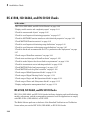
A test specification object with the following structure.
Field
Description
id
Read-only internal ID
modelcov
Read-only internal ID
rootPath
Name of system or subsystem for analysis
label
String used when reporting results
setupCmd
Command executed in base workspace prior to
simulation
settings.condition
Set to 1 for condition coverage.
settings.decision
Set to 1 for decision coverage.
settings.
designverifier
Set to 1 for coverage for Simulink Design Verifier™
blocks.
settings.mcdc
Set to 1 for MCDC coverage.
settings.relationalop
Set to 1 for relational boundary coverage. Use
options.
covBoundaryAbsTol and options.
covBoundaryRelTol for specifying tolerances for
this coverage.
For more information, see “Relational Boundary
Coverage”.
settings.sigrange
Set to 1 for signal range coverage.
settings.sigsize
Set to 1 for signal size coverage.
settings.tableExec
Set to 1 for lookup table coverage.
modelRefSettings.
enable
• 'off' — Disables coverage for all referenced
models.
• 'all' or on — Enables coverage for all
referenced models.
1-53
1
Functions — Alphabetical List
Field
Description
• 'filtered' — Enables coverage only
for referenced models not listed in the
excludedModels subfield.
modelRefSettings.
excludeTopModel
Set to 1 to exclude coverage for the top model
modelRefSettings.
excludedModels
String specifying a comma-separated list of
referenced models for which coverage is disabled.
emlSettings.
enableExternal
Set to 1 to enable coverage for external program files
called by MATLAB functions in your model.
sfcnSettings.
enableSfcn
Set to 1 to enable coverage for C/C++ S-Function
blocks in your model.
options.
forceBlockReduction
Set to 1 to override the Simulink Block reduction
parameter if it is enabled.
options.
covBoundaryRelTol
Set to the value of relative tolerance for relational
boundary coverage.
For more information, see “Relational Boundary
Coverage”.
options.
covBoundaryAbsTol
Set to the value of absolute tolerance for relational
boundary coverage.
For more information, see “Relational Boundary
Coverage”.
options.useTimeInterval
Set to 1 to restrict model coverage recording only
inside a specified simulation time interval.
For more information see “Specify Model Coverage
Options”.
1-54
options.intervalStartTime
Value of the coverage recording interval start time.
options.intervalStopTime
Value of the coverage recording interval stop time.
filter.fileName
String specifying name of coverage filter file, if you
have excluded objects from coverage recording. See
“Coverage Filter Rules and Files”.
cvtest
Examples
Create a cvtest object for the Adjustable Rate Limiter block in the
slvnvdemo_ratelim_harness model. Simulate and get coverage data using cvsim.
open_system('slvnvdemo_ratelim_harness');
testObj = cvtest(['slvnvdemo_ratelim_harness', ...
'/Adjustable Rate Limiter']);
testObj.label = 'Gain within slew limits';
testObj.setupCmd = ...
'load(''slvnvdemo_ratelim_harness_data.mat'');';
testObj.settings.decision = 1;
testObj.settings.overflowsaturation = 1;
cvdo = cvsim(testObj);
More About
•
“Create Tests with cvtest”
See Also
cvsim | cv.cvdatagroup
1-55
1
Functions — Alphabetical List
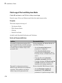
decisioninfo
Retrieve decision coverage information from cvdata object
Syntax
coverage = decisioninfo(cvdo, object)
coverage = decisioninfo(cvdo, object, ignore_descendants)
[coverage, description] = decisioninfo(cvdo, object)
Description
coverage = decisioninfo(cvdo, object) returns decision coverage results from
the cvdata object cvdo for the model component specified by object.
coverage = decisioninfo(cvdo, object, ignore_descendants) returns
decision coverage results for object, depending on the value of ignore_descendants.
[coverage, description] = decisioninfo(cvdo, object) returns decision
coverage results and text descriptions of decision points associated with object.
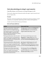
Input Arguments
cvdo
cvdata object
object
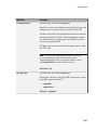
The object argument specifies an object in the model or Stateflow chart that received
decision coverage. Valid values for object include the following:
1-56
Object Specification
Description
BlockPath
Full path to a model or block
decisioninfo
Object Specification
Description
BlockHandle
Handle to a model or block
slObj
Handle to a Simulink API object
sfID
Stateflow ID
sfObj
Handle to a Stateflow API object from a singly
instantiated Stateflow chart
{BlockPath, sfID}
Cell array with the path to a Stateflow chart or
atomic subchart and the ID of an object contained
in that chart or subchart
{BlockPath, sfObj}
Cell array with the path to a Stateflow chart
or subchart and a Stateflow object API handle
contained in that chart or subchart
[BlockHandle, sfID]
Array with a handle to a Stateflow chart or
atomic subchart and the ID of an object contained
in that chart or subchart
ignore_descendants
Specifies to ignore the coverage of descendant objects if ignore_descendants is set to
1.
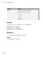
Output Arguments
coverage
The value of coverage is a two-element vector of the form [covered_outcomes
total_outcomes].coverage is empty if cvdo does not contain decision coverage
results for object. The two elements are:
covered_outcomes
Number of decision outcomes satisfied for
object
total_outcomes
Number of decision outcomes for object
description
description is a structure array containing the following fields:
1-57
1
Functions — Alphabetical List
decision.text
String describing a decision point, e.g., 'U
> LL'
decision.outcome.text
String describing a decision outcome, i.e.,
'true' or 'false'
decision.outcome.
executionCount
Number of times a decision outcome
occurred in a simulation
Examples
Open the slvnvdemo_cv_small_controller model and create the test specification
object testObj. Enable decision coverage for slvnvdemo_cv_small_controller and
execute testObj using cvsim. Use decisioninfo to retrieve the decision coverage
results for the Saturation block and determine the percentage of decision outcomes
covered:
mdl = 'slvnvdemo_cv_small_controller';
open_system(mdl)
testObj = cvtest(mdl)
testObj.settings.decision = 1;
data = cvsim(testObj)
blk_handle = get_param([mdl, '/Saturation'], 'Handle');
cov = decisioninfo(data, blk_handle)
percent_cov = 100 * cov(1) / cov(2)
Alternatives
Use the Coverage Settings dialog box to collect and display decision coverage results:
1-58
1
Open the model.
2
In the Model Editor, select Analysis > Coverage > Settings.
3
On the Coverage tab, select Coverage for this model.
4
Under Coverage metrics, select Decision.
5
On the Results and Reporting tabs, specify the output you need.
6
Click OK to close the Coverage Settings dialog box and save your changes.
7
Simulate the model and review the results.
decisioninfo
More About
•
“Decision Coverage (DC)”
See Also
complexityinfo | cvsim | conditioninfo | getCoverageInfo | mcdcinfo |
overflowsaturationinfo | sigrangeinfo | sigsizeinfo | tableinfo
1-59
1
Functions — Alphabetical List
get
Class: cv.cvdatagroup
Package: cv
Get cvdata object
Syntax
get(cvdg, model_name)
Description
get(cvdg, model_name) returns the cvdata object in the cv.cvdatagroup object
cvdg that corresponds to the model specified in model_name.
Examples
Get a cvdata object from the specified Simulink model:
get(cvdg, 'slvnvdemo_cv_small_controller');
1-60
getAll
getAll
Class: cv.cvdatagroup
Package: cv
Get all cvdata objects
Syntax
getAll(cvdo)
Description
getAll(cvdo) returns all cvdata objects in the cv.cvdatagroup object cvdo.
Examples
Return all cvdata objects from the specified Simulink model:
getAll(cvdg, 'slvnvdemo_cv_small_controller');
1-61
1
Functions — Alphabetical List
getCoverageInfo
Retrieve coverage information for Simulink Design Verifier blocks from cvdata object
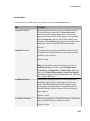
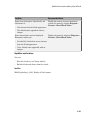
Syntax
[coverage, description] = getCoverageInfo(cvdo, object)
[coverage, description] = getCoverageInfo(cvdo, object, metric)
[coverage, description] = getCoverageInfo(cvdo, object, metric,
ignore_descendants)
Description
[coverage, description] = getCoverageInfo(cvdo, object) collects Simulink
Design Verifier coverage for object, based on coverage results in cvdo. object is a handle
to a block, subsystem, or Stateflow chart. getCoverageData returns coverage data only
for Simulink Design Verifier library blocks in object's hierarchy.
[coverage, description] = getCoverageInfo(cvdo, object, metric)
returns coverage data for the block type specified in metric. If object does not match the
block type, getCoverageInfo does not return data.
[coverage, description] = getCoverageInfo(cvdo, object, metric,
ignore_descendants) returns coverage data about object, omitting coverage data for
its descendant objects if ignore_descendants equals 1.
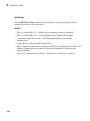
Input Arguments
cvdo
cvdata object
object
In the model or Stateflow chart, object that received Simulink Design Verifier coverage.
The following are valid values for object.
BlockPath
1-62
Full path to a model or block
getCoverageInfo
BlockHandle
Handle to a model or block
slObj
Handle to a Simulink API object
sfID
Stateflow ID from a singly instantiated Stateflow
chart
sfObj
Handle to a Stateflow API object from a singly
instantiated Stateflow chart
{BlockPath, sfID}
Cell array with the path to a Stateflow chart or
atomic subchart and the ID of an object contained
in that chart or subchart
{BlockPath, sfObj}
Cell array with the path to a Stateflow chart
or atomic subchart and a Stateflow object API
handle contained in that chart or subchart
[BlockHandle, sfID]
Array with a handle to a Stateflow chart or
atomic subchart and the ID of an object contained
in that chart or subchart
Default:
metric
cvmetric.Sldv enumeration object with values that correspond to Simulink Design
Verifier library blocks.
test
Test Objective block
proof
Proof Objective block
condition
Test Condition block
assumption
Proof Assumption block
ignore_descendants
Boolean value that specifies to ignore the coverage of descendant objects if set to 1.
Output Arguments
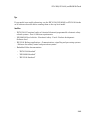
coverage
Two-element vector of the form [covered_outcomes total_outcomes].
1-63
1
Functions — Alphabetical List
covered_outcomes
Number of test objectives satisfied for
object
total_outcomes
Total number of test objectives for object
coverage is empty if cvdo does not contain decision coverage results for object.
description
Structure array containing descriptions of each test objective, and descriptions and
execution counts for each outcome within object.
Examples
Collect and display coverage data for the Test Objective block named True in the
sldvdemo_debounce_testobjblks model:
mdl = 'sldvdemo_debounce_testobjblks';
open_system(mdl)
testObj = cvtest(mdl)
testObj.settings.designverifier = 1;
data = cvsim(testObj)
blk_handle = get_param([mdl, '/True'], 'Handle');
getCoverageInfo(data, blk_handle)
Alternatives
Use the Coverage Settings dialog box to collect and display coverage results for Simulink
Design Verifier library blocks:
1
Open the model.
2
In the Model Editor, select Analysis > Coverage > Settings.
3
On the Coverage tab, select Coverage for this model.
4
Under Coverage metrics, select Simulink Design Verifier.
5
Click OK to close the Coverage Settings dialog box and save your changes.
6
Simulate the model and review the results.
More About
•
1-64
“Simulink Design Verifier Coverage”
getCoverageInfo
See Also
complexityinfo | cvsim | conditioninfo | decisioninfo | mcdcinfo |
overflowsaturationinfo | sigrangeinfo | sigsizeinfo | tableinfo
1-65
1
Functions — Alphabetical List
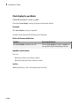
getEntry
Class: ModelAdvisor.Table
Package: ModelAdvisor
Get table cell contents
Syntax
content = getEntry(table, row, column)
Description
content = getEntry(table, row, column) gets the contents of the specified cell.
Input Arguments
table
Instantiation of the ModelAdvisor.Table class
row
An integer specifying the row
column
An integer specifying the column
Output Arguments
content
An element object or object array specifying the content of the
table entry
Examples
Get the content of the table cell in the third column, third row:
table1 = ModelAdvisor.Table(4, 4);
1-66
getEntry
.
.
.
content = getEntry(table1, 3, 3);
See Also
“Model Advisor Customization”
How To
•
“Create Model Advisor Checks”
1-67
1
Functions — Alphabetical List
getID
Class: ModelAdvisor.Check
Package: ModelAdvisor
Return check identifier
Syntax
id = getID(check_obj)
Description
id = getID(check_obj) returns the ID of the check check_obj. id is a unique string
that identifies the check.
You create this unique identifier when you create the check. This unique identifier is the
equivalent of the ModelAdvisor.Check ID property.
See Also
“Model Advisor Customization”
How To
1-68
•
“Define Custom Checks”
•
“Create Model Advisor Checks”
mcdcinfo
mcdcinfo
Retrieve modified condition/decision coverage information from cvdata object
Syntax
coverage = mcdcinfo(cvdo, object)
coverage = mcdcinfo(cvdo, object, ignore_descendants)
[coverage, description] = mcdcinfo(cvdo, object)
Description
coverage = mcdcinfo(cvdo, object) returns modified condition/decision coverage
(MCDC) results from the cvdata object cvdo for the model component specified by object.
coverage = mcdcinfo(cvdo, object, ignore_descendants) returns MCDC
results for object, depending on the value of ignore_descendants.
[coverage, description] = mcdcinfo(cvdo, object) returns MCDC results
and text descriptions of each condition/decision in object.
Input Arguments
cvdo
cvdata object
ignore_descendants
Logical value specifying whether to ignore the coverage of descendant objects
1 — Ignore coverage of descendant objects
0 — Collect coverage for descendant objects
object
The object argument specifies an object in the Simulink model or Stateflow diagram that
receives decision coverage. Valid values for object include the following:
1-69
1
Functions — Alphabetical List
Object Specification
Description
BlockPath
Full path to a model or block
BlockHandle
Handle to a model or block
slObj
Handle to a Simulink API object
sfID
Stateflow ID
sfObj
Handle to a Stateflow API object
{BlockPath, sfID}
Cell array with the path to a Stateflow chart
or atomic subchart and the ID of an object
contained in that chart or subchart
{BlockPath, sfObj}
Cell array with the path to a Stateflow chart
or atomic subchart and a Stateflow object API
handle contained in that chart or subchart
[BlockHandle, sfID]
Array with a handle to a Stateflow chart
or atomic subchart and the ID of an object
contained in that chart or subchart
Output Arguments
coverage
Two-element vector of the form [covered_outcomes total_outcomes]. coverage is
empty if cvdo does not contain modified condition/decision coverage results for object. The
two elements are:
covered_outcomes
Number of condition/decision outcomes
satisfied for object
total_outcomes
Total number of condition/decision
outcomes for object
description
A structure array containing the following fields:
text
1-70
String denoting whether the condition/
decision is associated with a block output or
Stateflow transition
mcdcinfo
condition.text
String describing a condition/decision or
the block port to which it applies
condition.achieved
Logical array indicating whether a
condition case has been fully covered
condition.trueRslt
String representing a condition case
expression that produces a true result
condition.falseRslt
String representing a condition case
expression that produces a false result
Examples
Collect MCDC coverage for the slvnvdemo_cv_small_controller model and
determine the percentage of MCDC coverage collected for the Logic block in the Gain
subsystem:
mdl = 'slvnvdemo_cv_small_controller';
open_system(mdl)
%Create test specification object
testObj = cvtest(mdl)
%Enable MCDC coverage
testObj.settings.mcdc = 1;
%Simulate model
data = cvsim(testObj)
%Retrieve MCDC results for Logic block
blk_handle = get_param([mdl, '/Gain/Logic'], 'Handle');
cov = mcdcinfo(data, blk_handle)
%Percentage of MCDC outcomes covered
percent_cov = 100 * cov(1) / cov(2)
Alternatives
Use the Coverage Settings dialog box to collect MCDC coverage for a model:
1
Open the model.
2
In the Model Editor, select Analysis > Coverage > Settings.
3
On the Coverage tab, select Coverage for this model.
4
Under Coverage metrics, select MCDC.
1-71
1
Functions — Alphabetical List
5
On the Results and Reporting tabs, specify the output you need.
6
Click OK to close the Coverage Settings dialog box and save your changes.
7
Simulate the model and review the MCDC coverage results.
More About
•
“Modified Condition/Decision Coverage (MCDC)”
•
“MCDC Analysis”
See Also
complexityinfo | cvsim | conditioninfo | decisioninfo | getCoverageInfo |
overflowsaturationinfo | sigrangeinfo | sigsizeinfo | tableinfo
1-72
ModelAdvisor.Action class
ModelAdvisor.Action class
Package: ModelAdvisor
Add actions to custom checks
Description
Instances of this class define actions you take when the Model Advisor checks do not
pass. Users access actions by clicking the Action button that you define in the Model
Advisor window.
Construction
ModelAdvisor.Action
Add actions to custom checks
Methods
setCallbackFcn
Specify action callback function
Properties
Description
Message in Action box
Name
Action button label
Copy Semantics
Handle. To learn how this affects your use of the class, see Copying Objects in the
MATLAB Programming Fundamentals documentation.
1-73
1
Functions — Alphabetical List
Examples
% define action (fix) operation
myAction = ModelAdvisor.Action;
myAction.Name='Fix block fonts';
myAction.Description=...
'Click the button to update all blocks with specified font';
See Also
“Model Advisor Customization”
How To
•
1-74
“Create Model Advisor Checks”
ModelAdvisor.Action
ModelAdvisor.Action
Class: ModelAdvisor.Action
Package: ModelAdvisor
Add actions to custom checks
Syntax
action_obj = ModelAdvisor.Action
Description
action_obj = ModelAdvisor.Action creates a handle to an action object.
Note:
• Include an action definition in a check definition.
• Each check can contain only one action.
Examples
% define action (fix) operation
myAction = ModelAdvisor.Action;
See Also
“Model Advisor Customization”
How To
•
“Create Model Advisor Checks”
1-75
1
Functions — Alphabetical List
ModelAdvisor.Check class
Package: ModelAdvisor
Create custom checks
Description
The ModelAdvisor.Check class creates a Model Advisor check object. Checks must
have an associated ModelAdvisor.Task object to be displayed in the Model Advisor
tree.
You can use one ModelAdvisor.Check object in multiple ModelAdvisor.Task objects,
allowing you to place the same check in multiple locations in the Model Advisor tree.
For example, Check for implicit signal resolution is displayed in the By Product >
Simulink folder and in the By Task > Model Referencing folder in the Model Advisor
tree.
When you use checks in task definitions, the following rules apply:
• If you define the properties of the check in the check definition and the task
definition, the task definition takes precedence. The Model Advisor displays the
information contained in the task definition. For example, if you define the name
of the check in the task definition using the ModelAdvisor.Task.DisplayName
property and in the check definition using the ModelAdvisor.Check.Title
property, the Model Advisor displays the information provided in
ModelAdvisor.Task.DisplayName.
• If you define the properties of the check in the check definition but not the task
definition, the task uses the properties from the check. For example, if you define the
name of the check in the check definition using the ModelAdvisor.Check.Title
property, and you register the check using a task definition, the Model Advisor
displays the information provided in ModelAdvisor.Check.Title.
• If you define the properties of the check in the task definition but not the check
definition, the Model Advisor displays the information as long as you register the
task with the Model Advisor instead of the check. For example, if you define the name
of the check in the task definition using the ModelAdvisor.Task.DisplayName
property instead of the ModelAdvisor.Check.Title property, and you register the
check using a task definition, the Model Advisor displays the information provided in
ModelAdvisor.Task.DisplayName.
1-76
ModelAdvisor.Check class
Construction
ModelAdvisor.Check
Create custom checks
Methods
getID
Return check identifier
setAction
Specify action for check
setCallbackFcn
Specify callback function for check
setInputParameters
Specify input parameters for check
setInputParametersLayoutGrid
Specify layout grid for input parameters
Properties
CallbackContext
Specify when to run check
CallbackHandle
Callback function handle for check
CallbackStyle
Callback function type
EmitInputParametersToReport
Display check input parameters in the
Model Advisor report
Enable
Indicate whether user can enable or disable
check
ID
Identifier for check
1-77
1
Functions — Alphabetical List
LicenseName
Product license names required to display
and run check
ListViewVisible
Status of Explore Result button
Result
Results cell array
supportExclusion
Set to support exclusions
SupportLibrary
Set to support library models
Title
Name of check
TitleTips
Description of check
Value
Status of check
Visible
Indicate to display or hide check
Copy Semantics
Handle. To learn how this affects your use of the class, see Copying Objects in the
MATLAB Programming Fundamentals documentation.
Examples
rec = ModelAdvisor.Check('com.mathworks.sample.Check1');
See Also
“Model Advisor Customization”
How To
•
1-78
“Create Model Advisor Checks”
ModelAdvisor.Check
ModelAdvisor.Check
Class: ModelAdvisor.Check
Package: ModelAdvisor
Create custom checks
Syntax
check_obj = ModelAdvisor.Check(check_ID)
Description
check_obj = ModelAdvisor.Check(check_ID) creates a check object, check_obj,
and assigns it a unique identifier, check_ID. check_ID must remain constant.
To display checks in the Model Advisor tree, checks must have an associated
ModelAdvisor.Task or ModelAdvisor.Root object.
Note: You can use one ModelAdvisor.Check object in multiple ModelAdvisor.Task
objects, allowing you to place the same check in multiple locations in the Model Advisor
tree. For example, Check for implicit signal resolution appears in the By Product
> Simulink folder and in the By Task > Model Referencing folder in the Model
Advisor tree.
Examples
rec = ModelAdvisor.Check('com.mathworks.sample.Check1');
See Also
“Model Advisor Customization”
How To
•
“Create Model Advisor Checks”
1-79
1
Functions — Alphabetical List
ModelAdvisor.FactoryGroup class
Package: ModelAdvisor
Define subfolder in By Task folder
Description
The ModelAdvisor.FactoryGroup class defines a new subfolder to add to the By Task
folder.
Construction
ModelAdvisor.FactoryGroup
Define subfolder in By Task folder
Methods
addCheck
Add check to folder
Properties
1-80
Description
Description of folder
DisplayName
Name of folder
ID
Identifier for folder
MAObj
Model Advisor object
ModelAdvisor.FactoryGroup class
Copy Semantics
Handle. To learn how this affects your use of the class, see Copying Objects in the
MATLAB Programming Fundamentals documentation.
Examples
% --- sample factory group
rec = ModelAdvisor.FactoryGroup('com.mathworks.sample.factorygroup');
See Also
“Model Advisor Customization”
How To
•
“Create Model Advisor Checks”
1-81
1
Functions — Alphabetical List
ModelAdvisor.FactoryGroup
Class: ModelAdvisor.FactoryGroup
Package: ModelAdvisor
Define subfolder in By Task folder
Syntax
fg_obj = ModelAdvisor.FactoryGroup(fg_ID)
Description
fg_obj = ModelAdvisor.FactoryGroup(fg_ID) creates a handle to a factory group
object, fg_obj, and assigns it a unique identifier, fg_ID. fg_ID must remain constant.
Examples
% --- sample factory group
rec = ModelAdvisor.FactoryGroup('com.mathworks.sample.factorygroup');
See Also
“Model Advisor Customization”
How To
•
1-82
“Create Model Advisor Checks”
ModelAdvisor.FormatTemplate class
ModelAdvisor.FormatTemplate class
Package: ModelAdvisor
Template for formatting Model Advisor analysis results
Description
Use the ModelAdvisor.FormatTemplate class to format the result of a check in the
analysis result pane of the Model Advisor for a uniform look and feel among the checks
you create. There are two formats for the analysis result:
• Table
• List
Construction
ModelAdvisor.FormatTemplate
Construct template object for formatting
Model Advisor analysis results
Methods
addRow
Add row to table
setCheckText
Add description of check to result
setColTitles
Add column titles to table
setInformation
Add description of subcheck to result
setListObj
Add list of hyperlinks to model objects
setRecAction
Add Recommended Action section and text
1-83
1
Functions — Alphabetical List
setRefLink
Add See Also section and links
setSubBar
Add line between subcheck results
setSubResultStatus
Add status to check or subcheck result
setSubResultStatusText
Add text below status in result
setSubTitle
Add title for subcheck in result
setTableInfo
Add data to table
setTableTitle
Add title to table
Copy Semantics
Handle. To learn how this affects your use of the class, see Copying Objects in the
MATLAB Programming Fundamentals documentation.
Examples
The following code creates two template objects, ft1 and ft2, and uses them to format
the result of running the check in a table and a list. The result identifies the blocks in
the model. The graphics following the code display the output as it appears in the Model
Advisor when the check passes and fails.
function sl_customization(cm)
% register custom checks
cm.addModelAdvisorCheckFcn(@defineModelAdvisorChecks);
% register custom factory group
cm.addModelAdvisorTaskFcn(@defineModelAdvisorTasks);
% ----------------------------% defines Model Advisor Checks
% ----------------------------function defineModelAdvisorChecks
1-84
ModelAdvisor.FormatTemplate class
% Define and register a sample check
rec = ModelAdvisor.Check('mathworks.example.SampleStyleOne');
rec.Title = 'Sample check for Model Advisor using the ModelAdvisor.FormatTemplate';
setCallbackFcn(rec, @SampleStyleOneCallback,'None','StyleOne');
mdladvRoot = ModelAdvisor.Root;
mdladvRoot.register(rec);
% ----------------------------% defines Model Advisor Tasks
% ----------------------------function defineModelAdvisorTasks
mdladvRoot = ModelAdvisor.Root;
% --- sample factory group
rec = ModelAdvisor.FactoryGroup('com.mathworks.sample.factorygroup');
rec.DisplayName='My Group 1';
rec.Description='Demo Factory Group';
rec.addCheck('mathworks.example.SampleStyleOne');
mdladvRoot.publish(rec); % publish inside By Group list
% ----------------------------% Sample Check With Subchecks Callback Function
% ----------------------------function ResultDescription = SampleStyleOneCallback(system)
mdladvObj = Simulink.ModelAdvisor.getModelAdvisor(system); % get object
%Initialize variables
ResultDescription={};
ResultStatus = false; % Default check status is 'Warning'
mdladvObj.setCheckResultStatus(ResultStatus);
% Create FormatTemplate object for first subcheck, specify table format
ft1 = ModelAdvisor.FormatTemplate('TableTemplate');
% Add information describing the overall check
setCheckText(ft1, ['Find and report all blocks in the model. '...
'(setCheckText method - Description of what the check reviews)']);
% Add information describing the subcheck
setSubTitle(ft1, 'Table of Blocks (setSubTitle method - Title of the subcheck)');
setInformation(ft1, ['Find and report all blocks in a table. '...
'(setInformation method - Description of what the subcheck reviews)']);
% Add See Also section for references to standards
setRefLink(ft1, {{'Standard 1 reference (setRefLink method)'},
{'Standard 2 reference (setRefLink method)'}});
% Add information to the table
setTableTitle(ft1, {'Blocks in the Model (setTableTitle method)'});
setColTitles(ft1, {'Index (setColTitles method)',
'Block Name (setColTitles method)'});
1-85
1
Functions — Alphabetical List
% Perform the check actions
allBlocks = find_system(system);
if length(find_system(system)) == 1
% Add status for subcheck
setSubResultStatus(ft1, 'Warn');
setSubResultStatusText(ft1, ['The model does not contain blocks. '...
'(setSubResultStatusText method - Description of result status)']);
setRecAction(ft1, {'Add blocks to the model. '...
'(setRecAction method - Description of how to fix the problem)'});
ResultStatus = false;
else
% Add status for subcheck
setSubResultStatus(ft1, 'Pass');
setSubResultStatusText(ft1, ['The model contains blocks. '...
'(setSubResultStatusText method - Description of result status)']);
for inx = 2 : length(allBlocks)
% Add information to the table
addRow(ft1, {inx-1,allBlocks(inx)});
end
ResultStatus = true;
end
% Pass table template object for subcheck to Model Advisor
ResultDescription{end+1} = ft1;
% Create FormatTemplate object for second subcheck, specify list format
ft2 = ModelAdvisor.FormatTemplate('ListTemplate');
% Add information describing the subcheck
setSubTitle(ft2, 'List of Blocks (setSubTitle method - Title of the subcheck)');
setInformation(ft2, ['Find and report all blocks in a list. '...
'(setInformation method - Description of what the subcheck reviews)']);
% Add See Also section for references to standards
setRefLink(ft2, {{'Standard 1 reference (setRefLink method)'},
{'Standard 2 reference (setRefLink method)'}});
% Last subcheck, supress line
setSubBar(ft2, false);
% Perform the subcheck actions
if length(find_system(system)) == 1
% Add status for subcheck
setSubResultStatus(ft2, 'Warn');
setSubResultStatusText(ft2, ['The model does not contain blocks. '...
'(setSubResultStatusText method - Description of result status)']);
setRecAction(ft2, {'Add blocks to the model. '...
'(setRecAction method - Description of how to fix the problem)'});
ResultStatus = false;
else
% Add status for subcheck
setSubResultStatus(ft2, 'Pass');
setSubResultStatusText(ft2, ['The model contains blocks. '...
'(setSubResultStatusText method - Description of result status)']);
% Add information to the list
1-86
ModelAdvisor.FormatTemplate class
setListObj(ft2, allBlocks);
end
% Pass list template object for the subcheck to Model Advisor
ResultDescription{end+1} = ft2;
% Set overall check status
mdladvObj.setCheckResultStatus(ResultStatus);
The following graphic displays the output as it appears in the Model Advisor when the
check passes.
1-87
1
Functions — Alphabetical List
1-88
ModelAdvisor.FormatTemplate class
The following graphic displays the output as it appears in the Model Advisor when the
check fails.
1-89
1
Functions — Alphabetical List
Alternatives
Use the Model Advisor Formatting API to format check analysis results. However, use
the ModelAdvisor.FormatTemplate class for a uniform look and feel among the
checks you create.
See Also
“Model Advisor Customization”
How To
1-90
•
“Create Model Advisor Checks”
•
“Format Model Advisor Results”
ModelAdvisor.FormatTemplate
ModelAdvisor.FormatTemplate
Class: ModelAdvisor.FormatTemplate
Package: ModelAdvisor
Construct template object for formatting Model Advisor analysis results
Syntax
obj = ModelAdvisor.FormatTemplate('type')
Description
obj = ModelAdvisor.FormatTemplate('type') creates a handle, obj, to an
object of the ModelAdvisor.FormatTemplate class. type is a string identifying the
format type of the template, either list or table. Valid values are ListTemplate and
TableTemplate.
You must return the result object to the Model Advisor to display the formatted result in
the analysis result pane.
Note: Use the ModelAdvisor.FormatTemplate class in check callbacks.
Examples
Create a template object, ft, and use it to create a list template:
ft = ModelAdvisor.FormatTemplate('ListTemplate');
See Also
“Model Advisor Customization”
How To
•
“Create Model Advisor Checks”
1-91
1
Functions — Alphabetical List
•
1-92
“Format Model Advisor Results”
ModelAdvisor.Group class
ModelAdvisor.Group class
Package: ModelAdvisor
Define custom folder
Description
The ModelAdvisor.Group class defines a folder that is displayed in the Model Advisor
tree. Use folders to consolidate checks by functionality or usage.
Construction
ModelAdvisor.Group
Define custom folder
Methods
addGroup
Add subfolder to folder
addProcedure
Add procedure to folder
addTask
Add task to folder
Properties
Description
Description of folder
DisplayName
Name of folder
ID
Identifier for folder
1-93
1
Functions — Alphabetical List
MAObj
Model Advisor object
Copy Semantics
Handle. To learn how this affects your use of the class, see Copying Objects in the
MATLAB Programming Fundamentals documentation.
See Also
“Model Advisor Customization”
How To
•
1-94
“Create Model Advisor Checks”
ModelAdvisor.Group
ModelAdvisor.Group
Class: ModelAdvisor.Group
Package: ModelAdvisor
Define custom folder
Syntax
group_obj = ModelAdvisor.Group(group_ID)
Description
group_obj = ModelAdvisor.Group(group_ID) creates a handle to a group object,
group_obj, and assigns it a unique identifier, group_ID. group_ID must remain
constant.
Examples
MAG = ModelAdvisor.Group('com.mathworks.sample.GroupSample');
See Also
“Model Advisor Customization”
How To
•
“Create Model Advisor Checks”
1-95
1
Functions — Alphabetical List
ModelAdvisor.Image class
Package: ModelAdvisor
Include image in Model Advisor output
Description
The ModelAdvisor.Image class adds an image to the Model Advisor output.
Construction
ModelAdvisor.Image
Include image in Model Advisor output
Methods
setHyperlink
Specify hyperlink location
setImageSource
Specify image location
Copy Semantics
Handle. To learn how this affects your use of the class, see Copying Objects in the
MATLAB Programming Fundamentals documentation.
See Also
“Model Advisor Customization”
How To
•
1-96
“Create Model Advisor Checks”
ModelAdvisor.Image class
•
“Format Model Advisor Results”
1-97
1
Functions — Alphabetical List
ModelAdvisor.Image
Class: ModelAdvisor.Image
Package: ModelAdvisor
Include image in Model Advisor output
Syntax
object = ModelAdvisor.Image
Description
object = ModelAdvisor.Image creates a handle to an image object, object, that the
Model Advisor displays in the output. The Model Advisor supports many image formats,
including, but not limited to, JPEG, BMP, and GIF.
Examples
image_obj = ModelAdvisor.Image;
See Also
“Model Advisor Customization”
How To
1-98
•
“Create Model Advisor Checks”
•
“Format Model Advisor Results”
ModelAdvisor.InputParameter class
ModelAdvisor.InputParameter class
Package: ModelAdvisor
Add input parameters to custom checks
Description
Instances of the ModelAdvisor.InputParameter class specify the input parameters a
custom check uses in analyzing the model. Access input parameters in the Model Advisor
window.
Construction
ModelAdvisor.InputParameter
Add input parameters to custom checks
Methods
setColSpan
Specify number of columns for input
parameter
setRowSpan
Specify rows for input parameter
Properties
Description
Description of input parameter
Entries
Drop-down list entries
Name
Input parameter name
1-99
1
Functions — Alphabetical List
Type
Input parameter type
Value
Value of input parameter
Copy Semantics
Handle. To learn how this affects your use of the class, see Copying Objects in the
MATLAB Programming Fundamentals documentation.
See Also
“Model Advisor Customization”
How To
•
1-100
“Create Model Advisor Checks”
ModelAdvisor.InputParameter
ModelAdvisor.InputParameter
Class: ModelAdvisor.InputParameter
Package: ModelAdvisor
Add input parameters to custom checks
Syntax
input_param = ModelAdvisor.InputParameter
Description
input_param = ModelAdvisor.InputParameter creates a handle to an input
parameter object, input_param.
Note: You must include input parameter definitions in a check definition.
Examples
Note: The following example is a fragment of code from the sl_customization.m file
for the example model, slvnvdemo_mdladv. The example does not execute as shown
without the additional content found in the sl_customization.m file.
1-101
1
Functions — Alphabetical List
rec = ModelAdvisor.Check('com.mathworks.sample.Check1');
rec.setInputParametersLayoutGrid([3 2]);
% define input parameters
inputParam1 = ModelAdvisor.InputParameter;
inputParam1.Name = 'Skip font checks.';
inputParam1.Type = 'Bool';
inputParam1.Value = false;
inputParam1.Description = 'sample tooltip';
inputParam1.setRowSpan([1 1]);
inputParam1.setColSpan([1 1]);
inputParam2 = ModelAdvisor.InputParameter;
inputParam2.Name = 'Standard font size';
inputParam2.Value='12';
inputParam2.Type='String';
inputParam2.Description='sample tooltip';
inputParam2.setRowSpan([2 2]);
inputParam2.setColSpan([1 1]);
inputParam3 = ModelAdvisor.InputParameter;
inputParam3.Name='Valid font';
inputParam3.Type='Combobox';
inputParam3.Description='sample tooltip';
inputParam3.Entries={'Arial', 'Arial Black'};
inputParam3.setRowSpan([2 2]);
inputParam3.setColSpan([2 2]);
rec.setInputParameters({inputParam1,inputParam2,inputParam3});
See Also
“Model Advisor Customization”
How To
•
1-102
“Create Model Advisor Checks”
ModelAdvisor.LineBreak class
ModelAdvisor.LineBreak class
Package: ModelAdvisor
Insert line break
Description
Use instances of the ModelAdvisor.LineBreak class to insert line breaks in the Model
Advisor outputs.
Construction
ModelAdvisor.LineBreak
Insert line break
Copy Semantics
Handle. To learn how this affects your use of the class, see Copying Objects in the
MATLAB Programming Fundamentals documentation.
See Also
“Model Advisor Customization”
How To
•
“Create Model Advisor Checks”
•
“Format Model Advisor Results”
1-103
1
Functions — Alphabetical List
ModelAdvisor.LineBreak
Class: ModelAdvisor.LineBreak
Package: ModelAdvisor
Insert line break
Syntax
ModelAdvisor.LineBreak
Description
ModelAdvisor.LineBreak inserts a line break into the Model Advisor output.
Examples
Add a line break between two lines of text:
result = ModelAdvisor.Paragraph;
addItem(result, [resultText1 ModelAdvisor.LineBreak resultText2]);
See Also
“Model Advisor Customization”
How To
1-104
•
“Create Model Advisor Checks”
•
“Format Model Advisor Results”
ModelAdvisor.List class
ModelAdvisor.List class
Package: ModelAdvisor
Create list class
Description
Use instances of the ModelAdvisor.List class to create list-formatted outputs.
Construction
ModelAdvisor.List
Create list class
Methods
addItem
Add item to list
setType
Specify list type
Copy Semantics
Handle. To learn how this affects your use of the class, see Copying Objects in the
MATLAB Programming Fundamentals documentation.
See Also
“Model Advisor Customization”
How To
•
“Create Model Advisor Checks”
1-105
1
Functions — Alphabetical List
•
1-106
“Format Model Advisor Results”
ModelAdvisor.List
ModelAdvisor.List
Class: ModelAdvisor.List
Package: ModelAdvisor
Create list class
Syntax
list = ModelAdvisor.List
Description
list = ModelAdvisor.List creates a list object, list.
Examples
subList = ModelAdvisor.List();
setType(subList, 'numbered')
addItem(subList, ModelAdvisor.Text('Sub entry 1', {'pass','bold'}));
addItem(subList, ModelAdvisor.Text('Sub entry 2', {'pass','bold'}));
See Also
“Model Advisor Customization”
How To
•
“Create Model Advisor Checks”
•
“Format Model Advisor Results”
1-107
1
Functions — Alphabetical List
ModelAdvisor.ListViewParameter class
Package: ModelAdvisor
Add list view parameters to custom checks
Description
The Model Advisor uses list view parameters to populate the Model Advisor Result
Explorer. Access the information in list views by clicking Explore Result in the Model
Advisor window.
Construction
ModelAdvisor.ListViewParameter
Add list view parameters to custom checks
Properties
Attributes
Attributes to display in Model Advisor
Report Explorer
Data
Objects in Model Advisor Result Explorer
Name
Drop-down list entry
Copy Semantics
Handle. To learn how this affects your use of the class, see Copying Objects in the
MATLAB Programming Fundamentals documentation.
1-108
ModelAdvisor.ListViewParameter class
Examples
Note: The following example is a fragment of code from the sl_customization.m file
for the example model, slvnvdemo_mdladv. The example does not execute as shown
without the additional content found in the sl_customization.m file.
mdladvObj = Simulink.ModelAdvisor.getModelAdvisor(system);
mdladvObj.setCheckResultStatus(true);
% define list view parameters
myLVParam = ModelAdvisor.ListViewParameter;
myLVParam.Name = 'Invalid font blocks'; % the name appeared at pull down filter
myLVParam.Data = get_param(searchResult,'object')';
myLVParam.Attributes = {'FontName'}; % name is default property
mdladvObj.setListViewParameters({myLVParam});
See Also
“Model Advisor Customization”
How To
•
“Create Model Advisor Checks”
1-109
1
Functions — Alphabetical List
ModelAdvisor.ListViewParameter
Class: ModelAdvisor.ListViewParameter
Package: ModelAdvisor
Add list view parameters to custom checks
Syntax
lv_param = ModelAdvisor.ListViewParameter
Description
lv_param = ModelAdvisor.ListViewParameter defines a list view, lv_param.
Note: Include list view parameter definitions in a check definition.
See Also
“Model Advisor Customization”
How To
1-110
•
“Define Model Advisor Result Explorer Views”
•
“Create Model Advisor Checks”
•
“Batch-Fix Warnings or Failures”
•
“Customization Example”
•
“getListViewParameters”
•
“setListViewParameters”
ModelAdvisor.lookupCheckID
ModelAdvisor.lookupCheckID
Package: ModelAdvisor
Look up Model Advisor check ID
Syntax
NewID = ModelAdvisor.lookupCheckID('OldCheckID')
Description
NewID = ModelAdvisor.lookupCheckID('OldCheckID') returns the check ID of
the check specified by OldCheckID. OldCheckID is the ID of a check prior to R2010b.
Input Arguments
OldCheckID
OldCheckID is the ID of a check prior to R2010b.
Output Arguments
NewID
Check ID that corresponds to the previous check ID identified by OldCheckID.
Examples
Look up the check ID for By Product > Simulink Verification and Validation
> Modeling Standards > DO-178C/DO-331 Checks > Check safety-related
optimization settings using the previous ID DO178B:OptionSet:
NewID = ModelAdvisor.lookupCheckID('DO178B:OptionSet');
1-111
1
Functions — Alphabetical List
Alternatives
“Archive and View Results”
More About
•
“Archive and View Results”
See Also
ModelAdvisor.run
1-112
ModelAdvisor.Paragraph class
ModelAdvisor.Paragraph class
Package: ModelAdvisor
Create and format paragraph
Description
The ModelAdvisor.Paragraph class creates and formats a paragraph object.
Construction
ModelAdvisor.Paragraph
Create and format paragraph
Methods
addItem
Add item to paragraph
setAlign
Specify paragraph alignment
Copy Semantics
Handle. To learn how this affects your use of the class, see Copying Objects in the
MATLAB Programming Fundamentals documentation.
Examples
% Check Simulation optimization setting
ResultDescription{end+1} = ModelAdvisor.Paragraph(['Check Simulation '...
'optimization settings:']);
1-113
1
Functions — Alphabetical List
See Also
“Model Advisor Customization”
How To
1-114
•
“Create Model Advisor Checks”
•
“Format Model Advisor Results”
ModelAdvisor.Paragraph
ModelAdvisor.Paragraph
Class: ModelAdvisor.Paragraph
Package: ModelAdvisor
Create and format paragraph
Syntax
para_obj = ModelAdvisor.Paragraph
Description
para_obj = ModelAdvisor.Paragraph defines a paragraph object para_obj.
Examples
% Check Simulation optimization setting
ResultDescription{end+1} = ModelAdvisor.Paragraph(['Check Simulation '...
'optimization settings:']);
See Also
“Model Advisor Customization”
How To
•
“Create Model Advisor Checks”
1-115
1
Functions — Alphabetical List
ModelAdvisor.Procedure class
Package: ModelAdvisor
Define custom procedures
Description
The ModelAdvisor.Procedure class defines a procedure that is displayed in the Model
Advisor tree. Use procedures to organize additional procedures or checks by functionality
or usage.
Construction
ModelAdvisor.Procedure
Define custom procedures
Properties
Description
Provides information about the procedure. Details about the procedure are displayed in
the right pane of the Model Advisor.
Default: ' ' (null string)
Name
Specifies the name of the procedure that is displayed in the Model Advisor.
Default: ' ' (null string)
ID
Specifies a permanent, unique identifier for the procedure.
Note:
1-116
ModelAdvisor.Procedure class
• You must specify this field.
• The value of ID must remain constant.
• The Model Advisor generates an error if ID is not unique.
• Procedure definitions must refer to other procedures by ID.
MAObj
Specifies a handle to the current Model Advisor object.
Methods
addProcedure
Add subprocedure to procedure
addTask
Add task to procedure
Copy Semantics
Handle. To learn how this affects your use of the class, see Copying Objects in the
MATLAB Programming Fundamentals documentation.
See Also
“Model Advisor Customization”
How To
•
“Create Procedures”
•
“Create a Procedural-Based Configuration”
•
“Create Model Advisor Checks”
1-117
1
Functions — Alphabetical List
ModelAdvisor.Procedure
Class: ModelAdvisor.Procedure
Package: ModelAdvisor
Define custom procedures
Syntax
procedure_obj = ModelAdvisor.Procedure(procedure_ID)
Description
procedure_obj = ModelAdvisor.Procedure(procedure_ID) creates a handle to
a procedure object, procedure_obj, and assigns it a unique identifier, procedure_ID.
procedure_ID must remain constant.
Examples
MAP = ModelAdvisor.Procedure('com.mathworks.sample.ProcedureSample');
See Also
“Model Advisor Customization”
How To
1-118
•
“Create Procedures”
•
“Create a Procedural-Based Configuration”
•
“Create Model Advisor Checks”
ModelAdvisor.Root class
ModelAdvisor.Root class
Package: ModelAdvisor
Identify root node
Description
The ModelAdvisor.Root class returns the root object.
Construction
ModelAdvisor.Root
Identify root node
Methods
publish
Publish object in Model Advisor root
register
Register object in Model Advisor root
Copy Semantics
Handle. To learn how this affects your use of the class, see Copying Objects in the
MATLAB Programming Fundamentals documentation.
See Also
“Model Advisor Customization”
How To
•
“Create Model Advisor Checks”
1-119
1
Functions — Alphabetical List
ModelAdvisor.Root
Class: ModelAdvisor.Root
Package: ModelAdvisor
Identify root node
Syntax
root_obj = ModelAdvisor.Root
Description
root_obj = ModelAdvisor.Root creates a handle to the root object, root_obj.
Examples
mdladvRoot = ModelAdvisor.Root;
See Also
“Model Advisor Customization”
How To
•
1-120
“Create Model Advisor Checks”
ModelAdvisor.run
ModelAdvisor.run
Package: ModelAdvisor
Run Model Advisor checks on systems
Syntax
SysResultObjArray = ModelAdvisor.run(SysList,CheckIDList,Name,Value)
SysResultObjArray = ModelAdvisor.run(SysList,'Configuration',
FileName,Name,Value)
Description
SysResultObjArray = ModelAdvisor.run(SysList,CheckIDList,Name,Value)
runs the Model Advisor on the systems provided by SysList with additional options
specified by one or more optional Name,Value pair arguments. CheckIDList contains cell
array of check IDs to run.
SysResultObjArray = ModelAdvisor.run(SysList,'Configuration',
FileName,Name,Value) runs the Model Advisor on the systems provided by SysList.
The list of checks to run is specified using a Model Advisor configuration file, specified by
FileName.
Input Arguments
SysList
Cell array of systems to run.
CheckIDList
Cell array of check IDs to run. For details on how to find check IDs, see “Finding Check
IDs”.
CheckIDList optionally can include input parameters for specific checks using the
following syntax; {'CheckID','InputParam',{'IP','IPV'}}, where IP is the input parameter
1-121
1
Functions — Alphabetical List
name and IPV is the corresponding input parameter value. You can specify several input
parameter name and value pair arguments in any order as IP1,IPV1,…,IPN,IPVN.
FileName
Name of the Model Advisor configuration file. For details on creating a configuration file,
see “Organize Checks and Folders Using the Model Advisor Configuration Editor”.
Name-Value Pair Arguments
Specify optional comma-separated pairs of Name,Value arguments. Name is the
argument name and Value is the corresponding value. Name must appear inside single
quotes (' '). You can specify several name and value pair arguments in any order as
Name1,Value1,...,NameN,ValueN.
'DisplayResults'
Setting DisplayResults to 'Summary' displays a summary of the system results in the
Command Window. Setting DisplayResults to 'Details' displays the following in the
Command Window:
• Which system the Model Advisor is checking while the run is in progress.
• For each system, the pass and fail results of each check.
• A summary of the system results.
Setting DisplayResults to 'None' displays no information in the Command Window.
Default: 'Summary'
'Force'
Setting Force to 'On' removes existing modeladvisor/system folders. Setting Force to
'Off' prompts you before removing existing modeladvisor/system folders.
Default: 'Off'
'ParallelMode'
Setting ParallelMode to 'On' runs the Model Advisor in parallel mode if you have a
Parallel Computing Toolbox license and a multicore machine. For an example, see
“Create a Function for Checking Multiple Systems in Parallel”.
Default: 'Off'
1-122
ModelAdvisor.run
'TempDir'
Setting TempDir to 'On' runs the Model Advisor from a temporary working folder, to
avoid concurrency issues when running using a parallel pool. For more information, see
“Resolving Data Concurrency Issues”. Setting TempDir to 'Off' runs the Model Advisor in
the current working folder.
Default: 'Off'
'ShowExclusions'
Setting ShowExclusions to 'On' lists Model Advisor check exclusions in the report.
Setting ShowExclusions to ‘Off’ does not list Model Advisor check exclusion in the report.
Default: 'On'
Output Arguments
SysResultObjArray
Cell array of ModelAdvisor.SystemResult objects, one for each model specified
in SysList. Each ModelAdvisor.SystemResult object contains an array of
CheckResultObj objects. Save SysResultObjArray to review results at a later time
without having to rerun the Model Advisor (see “Save and Load Process”).
CheckResultObj
Array of ModelAdvisor.CheckResult objects, one for each check that runs.
Examples
Runs the Model Advisor checks Check model diagnostic parameters and Check for
fully defined interface on the sldemo_auto_climatecontrol/Heater Control
and sldemo_auto_climatecontrol/AC Control subsystems:
% Create list of checks and models to run.
CheckIDList ={'mathworks.maab.jc_0021',...
'mathworks.iec61508.RootLevelInports'};
SysList={'sldemo_auto_climatecontrol/Heater Control',...
'sldemo_auto_climatecontrol/AC Control'};
1-123
1
Functions — Alphabetical List
% Run the Model Advisor.
SysResultObjArray = ModelAdvisor.run(SysList,CheckIDList);
Runs the Model Advisor configuration file slvnvdemo_mdladv_config.mat
on the sldemo_auto_climatecontrol/Heater Control and
sldemo_auto_climatecontrol/AC Control subsystems:
% Identify Model Advisor configuration file.
% Create list of models to run.
fileName = 'slvnvdemo_mdladv_config.mat';
SysList={'sldemo_auto_climatecontrol/Heater Control',...
'sldemo_auto_climatecontrol/AC Control'};
% Run the Model Advisor.
SysResultObjArray = ModelAdvisor.run(SysList,'Configuration',fileName);
Alternatives
• Use the Model Advisor GUI to run each system, one at a time.
• Create a script or function using the Simulink.ModelAdvisor class to run each
system, one at a time.
More About
Tips
• If you have a Parallel Computing Toolbox™ license and a multicore machine, Model
Advisor can run on multiple systems in parallel. You can run the Model Advisor in
parallel mode by using ModelAdvisor.run with ‘ParallelMode’ set to ‘On’. By
default, ‘ParallelMode’ is set to ‘Off’. When you use ModelAdvisor.run with
‘ParallelMode’ set to ‘On’, MATLAB automatically creates a parallel pool.
•
“Automate Model Advisor Check Execution”
•
“Finding Check IDs”
•
“Organize Checks and Folders Using the Model Advisor Configuration Editor”
•
“Save and Load Process”
See Also
ModelAdvisor.summaryReport | view | viewReport |
ModelAdvisor.lookupCheckID
1-124
ModelAdvisor.summaryReport
ModelAdvisor.summaryReport
Package: ModelAdvisor
Open Model Advisor Command-Line Summary report
Syntax
ModelAdvisor.summaryReport(SysResultObjArray)
Description
ModelAdvisor.summaryReport(SysResultObjArray) opens the Model Advisor
Command-Line Summary report in a web browser. SysResultObjArray is a cell array
of ModelAdvisor.SystemResult objects returned by ModelAdvisor.run.
Input Arguments
SysResultObjArray
Cell array of ModelAdvisor.SystemResult objects returned by ModelAdvisor.run.
Examples
Opens the Model Advisor Command-Line Summary report after running the Model
Advisor:
% Identify Model Advisor configuration file.
% Create list of models to run.
fileName = 'slvnvdemo_mdladv_config.mat';
SysList={'sldemo_auto_climatecontrol/Heater Control',...
'sldemo_auto_climatecontrol/AC Control'};
% Run the Model Advisor.
SysResultObjArray = ModelAdvisor.run(SysList,'Configuration',fileName);
% Open the Model Advisor Command-Line Summary report.
ModelAdvisor.summaryReport(SysResultObjArray)
1-125
1
Functions — Alphabetical List
Alternatives
“View Results in Model Advisor Command-Line Summary Report”
More About
•
“Automate Model Advisor Check Execution”
•
“Archive and View Model Advisor Run Results”
See Also
ModelAdvisor.run | view | viewReport
1-126
ModelAdvisor.Table class
ModelAdvisor.Table class
Package: ModelAdvisor
Create table
Description
Instances of the ModelAdvisor.Table class create and format a table. Specify the
number of rows and columns in a table, excluding the table title and table heading row.
Construction
ModelAdvisor.Table
Create table
Methods
getEntry
Get table cell contents
setColHeading
Specify table column title
setColHeadingAlign
Specify column title alignment
setColHeadingValign
Specify column title vertical alignment
setColWidth
Specify column widths
setEntries
Set contents of table
setEntry
Add cell to table
1-127
1
Functions — Alphabetical List
setEntryAlign
Specify table cell alignment
setEntryValign
Specify table cell vertical alignment
setHeading
Specify table title
setHeadingAlign
Specify table title alignment
setRowHeading
Specify table row title
setRowHeadingAlign
Specify table row title alignment
setRowHeadingValign
Specify table row title vertical alignment
Copy Semantics
Handle. To learn how this affects your use of the class, see Copying Objects in the
MATLAB Programming Fundamentals documentation.
See Also
“Model Advisor Customization”
How To
1-128
•
“Create Model Advisor Checks”
•
“Format Model Advisor Results”
ModelAdvisor.Table
ModelAdvisor.Table
Class: ModelAdvisor.Table
Package: ModelAdvisor
Create table
Syntax
table = ModelAdvisor.Table(row, column)
Description
table = ModelAdvisor.Table(row, column) creates a table object (table). The
Model Advisor displays the table object containing the number of rows (row) and columns
(column) that you specify.
Examples
Create two table objects
Create two table objects, table1 and table2. The Model Advisor displays table1 in the
results as a table with one row and one column. The Model Advisor display table2 in
the results as a table with two rows and three columns.
table1 = ModelAdvisor.Table(1,1);
table2 = ModelAdvisor.Table(2,3);
Create table with five rows and five columns
Create a table with five rows and five columns containing randomly generated numbers.
Use the following MATLAB code in a callback function. The Model Advisor displays
table1 in the results.
% ModelAdvisor.Table example
matrixData = rand(5,5) * 10^5;
1-129
1
Functions — Alphabetical List
% initialize a table with 5 rows and 5 columns (heading rows not counting)
table1 = ModelAdvisor.Table(5,5);
% set column headings
for n=1:5
table1.setColHeading(n, ['Column ', num2str(n)]);
end
% set alignment of second column heading
table1.setColHeadingAlign(2, 'center');
% set column width of second column
table1.setColWidth(2, 3);
% set row headings
for n=1:5
table1.setRowHeading(n, ['Row ', num2str(n)]);
end
% set Table content
for rowIndex=1:5
for colIndex=1:5
table1.setEntry(rowIndex, colIndex, ...
num2str(matrixData(rowIndex, colIndex)));
% set alignment of entries in second row
if colIndex == 2
table1.setEntryAlign(rowIndex, colIndex, 'center');
end
end
end
% overwrite content of cell 3,3 with a ModelAdvisor.Text
text = ModelAdvisor.Text('Example Text');
table1.setEntry(3,3, text)
See Also
ModelAdvisor.Table.setColHeading |
ModelAdvisor.Table.setColHeadingAlign |
1-130
ModelAdvisor.Table
ModelAdvisor.Table.setColWidth | ModelAdvisor.Table.setRowHeading
| ModelAdvisor.Table.setEntry | ModelAdvisor.Table.setEntryAlign |
ModelAdvisor.Text
How To
•
“Create Callback Functions and Results”
1-131
1
Functions — Alphabetical List
ModelAdvisor.Task class
Package: ModelAdvisor
Define custom tasks
Description
The ModelAdvisor.Task class is a wrapper for a check so that you can access the check
with the Model Advisor.
You can use one ModelAdvisor.Check object in multiple ModelAdvisor.Task objects,
allowing you to place the same check in multiple locations in the Model Advisor tree.
For example, Check for implicit signal resolution is displayed in the By Product >
Simulink folder and in the By Task > Model Referencing folder in the Model Advisor
tree.
When adding checks as tasks, the Model Advisor uses the task properties instead of the
check properties, except for Visible and LicenseName.
Construction
ModelAdvisor.Task
Define custom tasks
Methods
setCheck
Specify check used in task
Properties
Description
1-132
Description of task
ModelAdvisor.Task class
DisplayName
Name of task
Enable
Indicate if user can enable and disable task
ID
Identifier for task
LicenseName
Product license names required to display
and run task
MAObj
Model Advisor object
Value
Status of task
Visible
Indicate to display or hide task
Copy Semantics
Handle. To learn how this affects your use of the class, see Copying Objects in the
MATLAB Programming Fundamentals documentation.
Examples
MAT1 = ModelAdvisor.Task('com.mathworks.sample.TaskSample1');
MAT2 = ModelAdvisor.Task('com.mathworks.sample.TaskSample2');
MAT3 = ModelAdvisor.Task('com.mathworks.sample.TaskSample3');
See Also
“Model Advisor Customization”
How To
•
“Create Model Advisor Checks”
1-133
1
Functions — Alphabetical List
ModelAdvisor.Task
Class: ModelAdvisor.Task
Package: ModelAdvisor
Define custom tasks
Syntax
task_obj = ModelAdvisor.Task(task_ID)
Description
task_obj = ModelAdvisor.Task(task_ID) creates a task object, task_obj, with
a unique identifier, task_ID. task_ID must remain constant. If you do not specify
task_ID, the Model Advisor assigns a random task_ID to the task object.
You can use one ModelAdvisor.Check object in multiple ModelAdvisor.Task objects,
allowing you to place the same check in multiple locations in the Model Advisor tree.
For example, Check for implicit signal resolution appears in the By Product
> Simulink folder and in the By Task > Model Referencing folder in the Model
Advisor tree.
When adding checks as tasks, the Model Advisor uses the task properties instead of the
check properties, except for Visible and LicenseName.
Examples
In the following example, you create three task objects, MAT1, MAT2, and MAT3.
MAT1 = ModelAdvisor.Task('com.mathworks.sample.TaskSample1');
MAT2 = ModelAdvisor.Task('com.mathworks.sample.TaskSample2');
MAT3 = ModelAdvisor.Task('com.mathworks.sample.TaskSample3');
See Also
“Model Advisor Customization”
1-134
ModelAdvisor.Task
How To
•
“Create Model Advisor Checks”
1-135
1
Functions — Alphabetical List
ModelAdvisor.Text class
Package: ModelAdvisor
Create Model Advisor text output
Description
Instances of ModelAdvisor.Text class create formatted text for the Model Advisor
output.
Construction
ModelAdvisor.Text
Create Model Advisor text output
Methods
1-136
setBold
Specify bold text
setColor
Specify text color
setHyperlink
Specify hyperlinked text
setItalic
Italicize text
setRetainSpaceReturn
Retain spacing and returns in text
setSubscript
Specify subscripted text
setSuperscript
Specify superscripted text
ModelAdvisor.Text class
setUnderlined
Underline text
Copy Semantics
Handle. To learn how this affects your use of the class, see Copying Objects in the
MATLAB Programming Fundamentals documentation.
Examples
t1 = ModelAdvisor.Text('This is some text');
See Also
“Model Advisor Customization”
How To
•
“Create Model Advisor Checks”
•
“Format Model Advisor Results”
1-137
1
Functions — Alphabetical List
ModelAdvisor.Text
Class: ModelAdvisor.Text
Package: ModelAdvisor
Create Model Advisor text output
Syntax
text = ModelAdvisor.Text(content, {attribute})
Description
text = ModelAdvisor.Text(content, {attribute}) creates a text object for the
Model Advisor output.
Input Arguments
content
Optional string specifying the content of the text object. If
content is empty, empty text is output.
attribute
Optional cell array of strings specifying the formatting of the
content. If no attribute is specified, the output text has default
coloring with no formatting. Possible formatting options include:
• normal (default) — Text is default color and style.
• bold — Text is bold.
• italic — Text is italicized.
• underline — Text is underlined.
• pass — Text is green.
• warn — Text is yellow.
• fail — Text is red.
• keyword — Text is blue.
• subscript — Text is subscripted.
• superscript — Text is superscripted.
1-138
ModelAdvisor.Text
Output Arguments
text
The text object you create
Examples
text = ModelAdvisor.Text('Sub entry 1', {'pass','bold'})
See Also
“Model Advisor Customization”
How To
•
“Create Model Advisor Checks”
•
“Format Model Advisor Results”
1-139
1
Functions — Alphabetical List
overflowsaturationinfo
Retrieve saturation on integer overflow coverage from cvdata object
Syntax
coverage = overflowsaturationinfo(covdata, object)
coverage = overflowsaturationinfo(covdata, object,
ignore_descendants)
[coverage, description] = overflowsaturationinfo(covdata, object)
Description
coverage = overflowsaturationinfo(covdata, object) returns saturation on
integer overflow coverage results from the cvdata object covdata for the model object
specified by object and its descendants.
coverage = overflowsaturationinfo(covdata, object,
ignore_descendants) returns saturation on integer overflow coverage results from
the cvdata object covdata for the model object specified by object and, depending on the
value of ignore_descendants, descendant objects.
[coverage, description] = overflowsaturationinfo(covdata, object)
returns saturation on integer overflow coverage results from the cvdata object covdata
for the model object specified by object, and textual descriptions of each coverage
outcome.
Examples
Collect Saturation on Integer Overflow Coverage for MinMax Block
Collect saturation on integer overflow coverage information for a MinMax block in the
example model sldemo_fuelsys.
Open the sldemo_fuelsys example model. Create a model coverage test specification
object for the Mixing & Combustion subsystem of the Engine Gas Dynamics subsystem.
open_system('sldemo_fuelsys');
1-140
overflowsaturationinfo
testObj = cvtest('sldemo_fuelsys/Engine Gas Dynamics/' ...
'Mixing & Combustion');
In the model coverage test specification object, specify to collect saturation on overflow
coverage.
testObj.settings.overflowsaturation = 1;
Simulate the model and collect coverage results in a new cvdata object.
dataObj = cvsim(testObj);
Get the saturation on overflow coverage results for the MinMax block in the Mixing &
Combustion subsystem. The coverage results are stored in a two-element vector of the
form [covered_outcomes total_outcomes].
blockHandle = get_param('sldemo_fuelsys/' ...
'Engine Gas Dynamics/Mixing & Combustion/MinMax','Handle');
covResults = overflowsaturationinfo(dataObj, blockHandle)
covResults =
1
2
One out of two saturation on integer overflow decision outcomes were satisfied for the
MinMax block in the Mixing & Combustion subsystem, so it received 50% saturation on
integer overflow coverage.
Collect Saturation on Integer Overflow Coverage and Description for Example Model
Collect saturation on integer overflow coverage for the example model
slvnvdemo_saturation_on_overflow_coverage. Review collected coverage results
and description for Sum block in Controller subsystem.
Open the slvnvdemo_saturation_on_overflow_coverage example model.
open_system('slvnvdemo_saturation_on_overflow_coverage');
Simulate the model and collect coverage results in a new cvdata object.
dataObj = cvsim('slvnvdemo_saturation_on_overflow_coverage');
Retrieve saturation on integer overflow coverage results and description for the Sum
block in the Controller subsystem of the Test Unit subsystem.
[covResults covDesc] = overflowsaturationinfo(dataObj, ...
'slvnvdemo_saturation_on_overflow_coverage/Test Unit /' ...
1-141
1
Functions — Alphabetical List
'Controller/Sum')
covResults =
1
2
covDesc =
isFiltered: 0
decision: [1x1 struct]
One out of two saturation on integer overflow decision outcomes were satisfied for the
Sum block, so it received 50% saturation on integer overflow coverage.
Review the number of times the Sum block evaluated to each saturation on integer
overflow outcome during simulation.
covDesc.decision.outcome(1)
ans =
executionCount: 3
text: 'false'
covDesc.decision.outcome(2)
ans =
executionCount: 0
text: 'true'
During simulation, integer overflow did not occur in the Sum block.
If integer overflow is not possible for a block in your model, consider clearing the
Saturate on integer overflow block parameter to optimize efficiency of your generated
code.
•
“Command Line Verification Tutorial”
Input Arguments
covdata — Coverage results data
cvdata object
1-142
overflowsaturationinfo
Coverage results data, specified as a cvdata object.
object — Model or model component
full path | handle
Model or model component, specified as a full path, handle, or array of paths or handles.
Object Specification
Description
BlockPath
Full path to a model or block
BlockHandle
Handle to a model or block
slObj
Handle to a Simulink API object
sfID
Stateflow ID
sfObj
Handle to a Stateflow API object
{BlockPath, sfID}
Cell array with the path to a Stateflow chart
or atomic subchart and the ID of an object
contained in that chart or subchart
{BlockPath, sfObj}
Cell array with the path to a Stateflow chart
or atomic subchart and a Stateflow object API
handle contained in that chart or subchart
[BlockHandle, sfID]
Array with a handle to a Stateflow chart
or atomic subchart and the ID of an object
contained in that chart or subchart
Example: 'slvnvdemo_saturation_on_overflow_coverage'
Example: get_param('slvnvdemo_cv_small_controller/Saturation',
'Handle')
ignore_descendants — Preference to ignore coverage of descendant objects
0 (default) | 1
Preference to ignore coverage of descendant objects, specified as a logical value.
1 — Ignore coverage of descendant objects
0 — Collect coverage for descendant objects
Data Types: logical
1-143
1
Functions — Alphabetical List
Output Arguments
coverage — Saturation on overflow coverage results for object
numerical vector
Saturation on overflow coverage results, stored in a two-element vector of the form
[covered_outcomes total_outcomes]. The two elements are:
covered_outcomes
Number of saturation on integer overflow
outcomes satisfied for object
total_outcomes
Total number of saturation on integer
overflow outcomes for object
Data Types: double
description — Textual description of coverage outcomes
structure array
Textual description of coverage outcomes for the model component specified by object,
returned as a structure array. Depending on the types of model coverage collected, the
structure array can have different fields. If only saturation on overflow coverage is
collected, the structure array contains the following fields:
isFiltered
0 if the model component specified by object
is not excluded from coverage recording. 1
if the model component specified by object
is excluded from coverage recording. For
more information about excluding objects
from coverage, see “Coverage Filtering”.
decision.text
'Saturate on integer overflow'
decision.outcome
Structure array containing two fields for
each coverage outcome:
executionCount
1-144
Number of times
saturation on
integer overflow for
object evaluated
to the outcome
described by text.
overflowsaturationinfo
text
'true' or 'false'
Saturation on integer overflow has two
possible outcomes, 'true' and 'false'.
decision.isFiltered
0 if the model component specified by object
is not excluded from coverage recording. 1
if the model component specified by object
is excluded from coverage recording. For
more information about excluding objects
from coverage, see “Coverage Filtering”.
decision.filterRationale
Rationale for filtering the model component
specified by object, if object is excluded
from coverage and a rationale is specified.
For more information about excluding
objects from coverage, see “Coverage
Filtering”.
Data Types: struct
More About
•
“Saturate on Integer Overflow Coverage”
See Also
complexityinfo | conditioninfo | cvsim | cvtest | decisioninfo |
getCoverageInfo | mcdcinfo | sigrangeinfo | sigsizeinfo | tableinfo
1-145
1
Functions — Alphabetical List
relationalboundaryinfo
Retrieve relational boundary coverage from cvdata object
Syntax
coverage = relationalboundaryinfo(covdata, object)
coverage = relationalboundaryinfo(covdata, object,
ignore_descendants)
[coverage, description] = relationalboundaryinfo(covdata, object)
Description
coverage = relationalboundaryinfo(covdata, object) returns relational
boundary coverage results from the cvdata object covdata for the model object specified
by object and its descendants.
coverage = relationalboundaryinfo(covdata, object,
ignore_descendants) returns relational boundary coverage results from the cvdata
object covdata for the model object specified by object and, depending on the value of
ignore_descendants, descendant objects.
[coverage, description] = relationalboundaryinfo(covdata, object)
returns relational boundary coverage results from the cvdata object covdata for the
model object specified by object, and textual descriptions of each coverage outcome.
Examples
Collect Relational Boundary Coverage for Supported Block in Model
This example shows how to collect relational boundary coverage information for a
Saturation block in a model. For more information on blocks supported for relational
boundary coverage, see “Model Objects That Receive Coverage”.
Open the slvnvdemo_cv_small_controller model. Create a model coverage test
specification object for the model.
1-146
relationalboundaryinfo
open_system('slvnvdemo_cv_small_controller');
testObj = cvtest('slvnvdemo_cv_small_controller');
In the model coverage test specification object, activate relational boundary coverage.
testObj.settings.relationalop = 1;
Simulate the model and collect coverage results in a cvdata object.
dataObj = cvsim(testObj);
Obtain relational boundary coverage results for the Saturation block in
slvnvdemo_cv_small_controller. The coverage results are stored in a two-element
vector of the form [covered_outcomes total_outcomes].
blockHandle = get_param('slvnvdemo_cv_small_controller/Saturation','Handle');;
[covResults covDesc] = relationalboundaryinfo(dataObj, blockHandle)
covResults =
2
4
covDesc =
isFiltered: 0
decision: [1x2 struct]
The field decision is a 1 X 2 structure. Each element of decision corresponds to a
relational operation in the block. The Saturation block contains two comparisons. The
first comparison is with a lower limit and the second with an upper limit. Therefore,
decision is a 2-element structure.
View the first operation in the block that receives relational boundary coverage. For the
Saturation block, the first relational operation is input > lowerlimit.
covDesc.decision(1)
ans =
outcome: [1x2 struct]
text: 'input - lowerlimit'
isFiltered: 0
1-147
1
Functions — Alphabetical List
filterRationale: ''
The text field shows the two operands. The isFiltered field is set to 1 if the block
is filtered from relational boundary coverage. For more information, see “Coverage
Filtering”.
View results for the first relational operation in the block.
for(i=1:2)
covDesc.decision(1).outcome(i)
end
ans =
isActive: 1
execCount: 0
text: '[-tol..0]'
ans =
isActive: 1
execCount: 0
text: '(0..tol]'
View the second operation in the block that receives relational boundary coverage. For
the Saturation block, the second relational operation is input < upperlimit.
covDesc.decision(2)
ans =
outcome:
text:
isFiltered:
filterRationale:
[1x2 struct]
'input - upperlimit'
0
''
View results for the second relational operation in the block.
for(i=1:2)
covDesc.decision(2).outcome(i)
end
ans =
1-148
relationalboundaryinfo
isActive: 1
execCount: 1
text: '[-tol..0)'
ans =
isActive: 1
execCount: 2
text: '[0..tol]'
•
“Command Line Verification Tutorial”
Input Arguments
covdata — Coverage results data
cvdata object
Coverage results data, specified as a cvdata object.
object — Model or model component
full path | handle
Model or model component, specified as a full path, handle, or array of paths or handles.
Object Specification
Description
BlockPath
Full path to a model or block
BlockHandle
Handle to a model or block
slObj
Handle to a Simulink API object
sfID
Stateflow ID
sfObj
Handle to a Stateflow API object
{BlockPath, sfID}
Cell array with the path to a Stateflow chart
or atomic subchart and the ID of an object
contained in that chart or subchart
{BlockPath, sfObj}
Cell array with the path to a Stateflow chart
or atomic subchart and a Stateflow object API
handle contained in that chart or subchart
1-149
1
Functions — Alphabetical List
Object Specification
Description
[BlockHandle, sfID]
Array with a handle to a Stateflow chart
or atomic subchart and the ID of an object
contained in that chart or subchart
Example: get_param('slvnvdemo_cv_small_controller/Saturation',
'Handle')
ignore_descendants — Preference to ignore coverage of descendant objects
0 (default) | 1
Preference to ignore coverage of descendant objects, specified as a logical value.
1 — Ignore coverage of descendant objects
0 — Collect coverage for descendant objects
Data Types: logical
Output Arguments
coverage — Relational boundary coverage results for object
numerical vector
Relational boundary coverage results, stored in a two-element vector of the form
[covered_outcomes total_outcomes]. The two elements are:
covered_outcomes
Number of relational boundary outcomes
satisfied for object
total_outcomes
Total number of relational boundary
outcomes for object
Data Types: double
description — Textual description of coverage outcomes
structure array
Textual description of coverage outcomes for the model component specified by object,
returned as a structure array. Depending on the types of model coverage collected, the
1-150
relationalboundaryinfo
structure array can have different fields. If only relational boundary coverage is collected,
the structure array contains the following fields:
isFiltered
0 if the model component specified by object
is not excluded from coverage recording. 1
if the model component specified by object
is excluded from coverage recording. For
more information about excluding objects
from coverage, see “Coverage Filtering”.
decision.text
String of the form:
op_1-op_2
• op_1 is the left operand in the
relational operation.
• op_2 is the right operand in the
relational operation.
decision.outcome
Structure array containing two fields for
each coverage outcome:
isActive
Boolean variable.
If this variable is
false, it indicates
that decisions were
not evaluated during
simulation due to
variable signal size.
execCount
Number of times
op_1-op_2 fell in
the range described
by text
text
The range around
the relational
boundary considered
for coverage. For
more information,
see “Relational
Boundary”.
1-151
1
Functions — Alphabetical List
decision.isFiltered
0 if the model component specified by object
is not excluded from coverage recording. 1
if the model component specified by object
is excluded from coverage recording. For
more information about excluding objects
from coverage, see “Coverage Filtering”.
decision.filterRationale
Rationale for filtering the model component
specified by object, if object is excluded
from coverage and a rationale is specified.
For more information about excluding
objects from coverage, see “Coverage
Filtering”.
Data Types: struct
More About
•
“Relational Boundary Coverage”
See Also
complexityinfo | conditioninfo | cvsim | cvtest | decisioninfo |
getCoverageInfo | mcdcinfo | overflowsaturationinfo | sigrangeinfo |
sigsizeinfo | tableinfo
1-152
publish
publish
Class: ModelAdvisor.Root
Package: ModelAdvisor
Publish object in Model Advisor root
Syntax
publish(root_obj,
publish(root_obj,
publish(root_obj,
publish(root_obj,
check_obj, location)
group_obj)
procedure_obj)
fg_obj)
Description
publish(root_obj, check_obj, location) specifies where the Model Advisor
places the check in the Model Advisor tree. location is either one of the subfolders
in the By Product folder, or the name of a new subfolder to put in the By Product
folder. Use a pipe-delimited string to indicate multiple subfolders. For example, to add a
check to the Simulink Verification and Validation > Modeling Standards folder,
use the following string: 'Simulink Verification and Validation|Modeling
Standards'.
If the By Product is not displayed in the Model Advisor window, select Show By
Product Folder from the Settings > Preferences dialog box.
publish(root_obj, group_obj) specifies the ModelAdvisor.Group object to
publish as a folder in the Model Advisor Task Manager folder.
publish(root_obj, procedure_obj) specifies the ModelAdvisor.Procedure
object to publish.
publish(root_obj, fg_obj) specifies the ModelAdvisor.FactoryGroup object to
publish as a subfolder in the By Task folder.
1-153
1
Functions — Alphabetical List
Examples
% publish check into By Product > Demo group.
mdladvRoot.publish(rec, 'Demo');
How To
1-154
•
“Define Where Custom Checks Appear”
•
“Define Where Tasks Appear”
•
“Define Where Custom Folders Appear”
register
register
Class: ModelAdvisor.Root
Package: ModelAdvisor
Register object in Model Advisor root
Syntax
register(MAobj, obj)
Description
register(MAobj, obj) registers the object, obj, in the root object MAobj.
In the Model Advisor memory, the register method registers the following types of
objects:
• ModelAdvisor.Check
• ModelAdvisor.FactoryGroup
• ModelAdvisor.Group
• ModelAdvisor.Procedure
• ModelAdvisor.Task
The register method places objects in the Model Advisor memory that you use in other
functions. The register method does not place objects in the Model Advisor tree.
Examples
mdladvRoot = ModelAdvisor.Root;
MAT1 = ModelAdvisor.Task('com.mathworks.sample.TaskSample1');
MAT1.DisplayName='Example task with input parameter and auto-fix ability';
MAT1.setCheck('com.mathworks.sample.Check1');
mdladvRoot.register(MAT1);
MAT2 = ModelAdvisor.Task('com.mathworks.sample.TaskSample2');
MAT2.DisplayName='Example task 2';
1-155
1
Functions — Alphabetical List
MAT2.setCheck('com.mathworks.sample.Check2');
mdladvRoot.register(MAT2);
MAT3 = ModelAdvisor.Task('com.mathworks.sample.TaskSample3');
MAT3.DisplayName='Example task 3';
MAT3.setCheck('com.mathworks.sample.Check3');
mdladvRoot.register(MAT3)
1-156
rmi
rmi
Interact programmatically with Requirements Management Interface
Syntax
reqlinks = rmi('createEmpty')
reqlinks = rmi('get', model)
reqlinks = rmi('get', sig_builder, group_idx)
rmi('set', model, reqlinks)
rmi('set', sig_builder, reqlinks, group_idx)
rmi('cat', model, reqlinks)
cnt = rmi('count', model)
rmi('clearAll', object)
rmi('clearAll', object, 'deep')
rmi('clearAll', object, 'noprompt')
rmi('clearAll', object, 'deep', 'noprompt')
cmdStr = rmi('navCmd', object)
[cmdStr, titleStr] = rmi('navCmd', object)
object = rmi('guidlookup', model, guidStr)
rmi('highlightModel', object)
rmi('unhighlightModel', object)
rmi('view', object, index)
dialog = rmi('edit', object)
guidStr = rmi('guidget', object)
rmi('report', model)
rmi('report', matlabfilepath)
rmi('projectreport')
rmi
rmi
rmi
rmi
setup
register linktypename
unregister linktypename
linktypelist
number_problems = rmi('checkdoc')
number_problems = rmi('checkdoc', docName)
1-157
1
Functions — Alphabetical List
rmi('check', matlabfilepath)
rmi('doorssync', model)
rmi('setDoorsLabelTemplate', template)
template = rmi('getDoorsLabelTemplate')
label = rmi('doorsLabel', moduleID, objectID)
totalModifiedLinks = rmi('updateDoorsLabels', model)
Description
reqlinks = rmi('createEmpty') creates an empty instance of the requirement links
data structure.
reqlinks = rmi('get', model) returns the requirement links data structure for
model.
reqlinks = rmi('get', sig_builder, group_idx) returns the requirement links
data structure for the Signal Builder group specified by the index group_idx.
rmi('set', model, reqlinks) sets reqlinks as the requirements links for model.
rmi('set', sig_builder, reqlinks, group_idx) sets reqlinks as the
requirements links for the signal group group_idx in the Signal Builder block sig_builder.
rmi('cat', model, reqlinks) adds the requirements links in reqlinks to existing
requirements links for model.
cnt = rmi('count', model) returns the number of requirements links for model.
rmi('clearAll', object) deletes all requirements links for object.
rmi('clearAll', object, 'deep') deletes all requirements links in the model
containing object.
rmi('clearAll', object, 'noprompt') deletes all requirements links for object
and does not prompt for confirmation.
rmi('clearAll', object, 'deep', 'noprompt') deletes all requirements links in
the model containing object and does not prompt for confirmation.
1-158
rmi
cmdStr = rmi('navCmd', object) returns the MATLAB command string cmdStr
used to navigate to object.
[cmdStr, titleStr] = rmi('navCmd', object) returns the MATLAB command
string cmdStr and the title string titleStr that provides descriptive text for object.
object = rmi('guidlookup', model, guidStr) returns the object name in
model that has the globally unique identifier guidStr.
rmi('highlightModel', object) highlights all of the objects in the parent model of
object that have requirement links.
rmi('unhighlightModel', object) removes highlighting of objects in the parent
model of object that have requirement links.
rmi('view', object, index) accesses the requirement numbered index in the
requirements document associated with object.
dialog = rmi('edit', object) displays the Requirements dialog box for object and
returns the handle of the dialog box.
guidStr = rmi('guidget', object) returns the globally unique identifier for
object. A globally unique identifier is created for object if it lacks one.
rmi('report', model) generates a Requirements Traceability report in HTML format
for model.
rmi('report', matlabfilepath) generates a Requirements Traceability report in
HTML format for the MATLAB code file specified by matlabfilepath.
rmi('projectreport') generates a Requirements Traceability report in HTML format
for the current Simulink Project. The master page of this report has HTTP links to
reports for each project item that has requirements traceability associations. For more
information, see “Create Requirements Traceability Report for Simulink Project”.
rmi setup configures RMI for use with your MATLAB software and installs the
interface for use with the IBM® Rational® DOORS® software.
rmi register linktypename registers the custom link type specified by the function
linktypename. For more information, see “Custom Link Type Registration”.
rmi unregister linktypename removes the custom link type specified by the
function linktypename. For more information, see “Custom Link Type Registration”.
1-159
1
Functions — Alphabetical List
rmi linktypelist displays a list of the currently registered link types. The list
indicates whether each link type is built-in or custom, and provides the path to the
function used for its registration.
number_problems = rmi('checkdoc') checks validity of links to Simulink from
a requirements document in Microsoft® Word, Microsoft Excel®, or IBM Rational
DOORS. It prompts for the requirements document name, returns the total number of
problems detected, and opens an HTML report in the MATLAB Web browser. For more
information, see “Validate Requirements Links in a Requirements Document”.
number_problems = rmi('checkdoc', docName) checks validity of links to
Simulink from the requirements document specified by docName. It returns the total
number of problems detected and opens an HTML report in the MATLAB Web browser.
For more information, see “Validate Requirements Links in a Requirements Document”.
rmi('check', matlabfilepath) checks consistency of traceability links associated
with MATLAB code lines in the .m file matlabfilepath, and opens an HTML report in the
MATLAB Web browser.
rmi('doorssync', model) opens the DOORS synchronization settings dialog box,
where you can customize the synchronization settings and synchronize your model
with an open project in an IBM Rational DOORS database. See rmi.doorssync for
information about synchronizing your model with DOORS at the MATLAB command
line.
rmi('setDoorsLabelTemplate', template) specifies a new custom
template for labels of requirements links to IBM Rational DOORS. The default
label template contains the section number and object heading for the DOORS
requirement link target. To revert the link label template back to the default, enter
rmi('setDoorsLabelTemplate', '') at the MATLAB command prompt.
template = rmi('getDoorsLabelTemplate') returns the currently specified
custom template for labels of requirements links to IBM Rational DOORS.
label = rmi('doorsLabel', moduleID, objectID) generates a label for the
requirements link to the IBM Rational DOORS object specified by objectID in the
DOORS module specified by moduleID, according to the current template.
totalModifiedLinks = rmi('updateDoorsLabels', model) updates all IBM
Rational DOORS requirements links labels in model according to the current template.
1-160
rmi
Examples
Requirements Links Management in Example Model
Get a requirement associated with a block in the slvnvdemo_fuelsys_htmreq model,
change its description, and save the requirement back to that block. Define a new
requirement link and add it to the existing requirements links in the block.
Get requirement link associated with the Airflow calculation block in the
slvnvdemo_fuelsys_htmreq example model.
slvnvdemo_fuelsys_htmreq;
blk_with_req = ['slvnvdemo_fuelsys_htmreq/fuel rate' 10 'controller/...
Airflow calculation'];
reqts = rmi('get', blk_with_req);
Change the description of the requirement link.
reqts.description = 'Mass airflow estimation';
Save the changed requirement link description for the Airflow calculation block.
rmi('set', blk_with_req, reqts);
Create new requirement link to example document fuelsys_requirements2.htm.
new_req = rmi('createempty');
new_req.doc = 'fuelsys_requirements2.htm';
new_req.description = 'A new requirement';
Add new requirement link to existing requirements links for the Airflow calculation
block.
rmi('cat', blk_with_req, new_req);
Requirements Traceability Report for Example Model
Create HTML report of requirements traceability data in example model.
Create an HTML requirements report for the slvnvdemo_fuelsys_htmreq example
model.
rmi('report', 'slvnvdemo_fuelsys_htmreq');
1-161
1
Functions — Alphabetical List
The MATLAB Web browser opens, showing the report.
Labels for Requirements Links to IBM Rational DOORS
Specify a new label template for links to requirements in DOORS, and update labels of
all DOORS requirements links in your model to fit the new template.
Specify a new label template for requirements links to IBM Rational DOORS so that new
links to DOORS objects are labeled with the corresponding module ID, object absolute
number, and the value of the ‘Backup’ attribute.
rmi('setDoorsLabelTemplate', '%m:%n [backup=%<Backup>]');
Update existing DOORS requirements link labels to match the new specified template
in your model example_model. When updating labels, DOORS must be running and all
linked modules must be accessible for reading.
rmi('updateDoorsLabels', example_model);
Input Arguments
model — Simulink or Stateflow model with which requirements can be associated
name | handle
Simulink or Stateflow model with which requirements can be associated, specified as a
string or handle.
Example: 'slvnvdemo_officereq'
Data Types: char
object — Model object with which requirements can be associated
name | handle
Model object with which requirements can be associated, specified as a string or handle.
Example: 'slvnvdemo_fuelsys_htmreq/fuel rate controller/Airflow
calculation'
Data Types: char
sig_builder — Signal Builder block containing signal group with requirements traceability
associations
name | handle
1-162
rmi
Signal Builder block containing signal group with requirements traceability associations,
specified as a string or handle.
Data Types: char
group_idx — Signal Builder group index
integer
Signal Builder group index, specified as a scalar.
Example: 2
Data Types: char
matlabfilepath — MATLAB code file with requirements traceability associations
path
MATLAB code file with requirements traceability associations, specified as the path to
the file.
Example:
Data Types: char
guidStr — Globally unique identifier for model object
string
Globally unique identifier for model object object, specified as a string.
Example: GIDa_59e165f5_19fe_41f7_abc1_39c010e46167
Data Types: char
index — Index number of requirement linked to model object
integer
Index number of requirement linked to model object, specified as an integer.
docName — Requirements document in external application
file name | path
Requirements document in external application, specified as a string that represents one
of the following:
• IBM Rational DOORS module ID.
1-163
1
Functions — Alphabetical List
• path to Microsoft Word requirements document.
• path to Microsoft Excel requirements document.
For more information, see “Validate Requirements Links in a Requirements Document”.
label — Label for links to requirements in IBM Rational DOORS
string
Example:
Data Types: char
template — Template label for links to requirements in IBM Rational DOORS
string
Template label for links to requirements in IBM Rational DOORS, specified as a string.
You can use the following format specifiers to include the associated DOORS information
in your requirements links labels:
%h
Object heading
%t
Object text
%p
Module prefix
%n
Object absolute number
%m
Module ID
%P
Project name
%M
Module name
%U
DOORS URL
%<ATTRIBUTE_NAME>
Other DOORS attribute you specify
Example: '%m:%n [backup=%<Backup>]'
Data Types: char
moduleID — IBM Rational DOORS module
DOORS module ID
IBM Rational DOORS module, specified as the unique DOORS module ID.
Example:
1-164
rmi
Data Types: char
objectID — IBM Rational DOORS object
DOORS object ID
IBM Rational DOORS object in the DOORS module moduleID, specified as the locally
unique DOORS ID.
Example:
Data Types: char
Output Arguments
reqlinks — Requirement links data
struct
Requirement links data, returned as a structure array with the following fields:
doc
String identifying requirements document
id
String defining location in requirements document. The first
character specifies the identifier type:
First
Character
Identifier
Example
?
Search text, the first
occurrence of which is
located in requirements
document
'?Requirement 1'
@
Named item, such as
'@my_req'
bookmark in a Microsoft
Word file or an anchor in an
HTML file
#
Page or item number
'#21'
>
Line number
'>3156'
$
Worksheet range in a
spreadsheet
'$A2:C5'
1-165
1
Functions — Alphabetical List
linked
Boolean value specifying whether the requirement link is accessible
for report generation and highlighting:
1 (default). Highlight model object and include requirement link in
reports.
0
description
String describing the requirement
keywords
Optional string supplementing description
reqsys
String identifying the link type registration name; 'other' for
built-in link types
cmdStr — Command string used to navigate to model object
string
Command string used to navigate to model object object, returned as a string.
Example: rmiobjnavigate('slvnvdemo_fuelsys_officereq.slx',
'GIDa_59e165f5_19fe_41f7_abc1_39c010e46167');
titleStr — Textual description of model object with requirements links
string
Textual description of model object with requirements links, returned as a string.
Example: slvnvdemo_fuelsys_officereq/.../Airflow calculation/Pumping
Constant (Lookup2D)
guidStr — Globally unique identifier for model object
string
Globally unique identifier for model object object, returned as a string.
Example: GIDa_59e165f5_19fe_41f7_abc1_39c010e46167
dialog — Requirements dialog box for model object
handle
Requirements dialog box for model object object, returned as a handle to the dialog box.
number_problems — Total count of invalid links detected in external document
integer
Total count of invalid links detected in external document docName.
1-166
rmi
For more information, see “Validate Requirements Links in a Requirements Document”.
totalModifiedLinks — Total count of DOORS requirements links updated with new label
template
integer
Total count of DOORS requirements links updated with new label template.
More About
•
“Requirements Management Interface Setup”
•
“Maintenance of Requirements Links”
See Also
rmi.doorssync | rmidata.default | rmidocrename | rmimap.map |
rmiobjnavigate | rmipref | rmitag | RptgenRMI.doorsAttribs
1-167
1
Functions — Alphabetical List
rmidata.default
Specify default storage location of requirements traceability data for new models
Syntax
rmidata.default(storage_setting)
Description
rmidata.default(storage_setting) specifies whether requirements traceability
data for new Simulink models is stored in the model file or in an external .req file. This
function does not affect models that already have saved requirements traceability data.
Input Arguments
storage_setting
String that specifies where requirements traceability data for a model is stored:
• 'internal' — Store requirements traceability data in the model file.
• 'external' — Store requirements traceability data in a separate file. The default
name for this file is model_name.req.
Examples
Specify to store requirements traceability data in the model file:
rmidata.default('internal');
Specify to store requirements traceability data in an external .req file:
rmidata.default('external);
1-168
rmidata.default
Alternatives
To set the storage location from the Simulink Editor:
1
Select Analysis > Requirements > Settings.
2
Select the Storage tab.
3
Select one of the following options:
• Store internally (embedded in a model file)
• Store externally (in a separate *.req file)
More About
•
“Specify Storage for Requirements Links”
•
“Requirements Link Storage”
See Also
rmi | rmidata.export | rmimap.map | rmidata.save
1-169
1
Functions — Alphabetical List
rmidata.export
Move requirements traceability data to external .req file
Syntax
[total_linked,total_links] = rmidata.export
[total_linked,total_links] = rmidata.export(model)
Description
[total_linked,total_links] = rmidata.export moves requirements
traceability data associated with the current Simulink model to an external file named
model_name.req. rmidata.export saves the file in the same folder as the model.
rmidata.export deletes the requirements traceability data stored in the model and
saves the modified model.
[total_linked,total_links] = rmidata.export(model) moves requirements
traceability data associated with model to an external file named model_name.req.
rmidata.export saves the file in the same folder as model. rmidata.export deletes
the requirements traceability data stored in the model and saves the modified model.
Input Arguments
model
Name or handle of a Simulink model
Output Arguments
total_linked
Integer indicating the number of objects in the model that have linked requirements
total_links
Integer indicating the total number of requirements links in the model
1-170
rmidata.export
Examples
Move the requirements traceability data from the slvnvdemo_fuelsys_officereq
model to an external file:
rmidata.export('slvnvdemo_fuelsys_officereq');
More About
•
“Specify Storage for Requirements Links”
•
“Requirements Link Storage”
See Also
rmi | rmidata.save | rmidata.default | rmimap.map
1-171
1
Functions — Alphabetical List
rmimap.map
Associate externally stored requirements traceability data with model
Syntax
rmimap.map(model,reqts_file)
rmimap.map(model,'undo')
rmimap.map(model,'clear')
Description
rmimap.map(model,reqts_file) associates the requirements traceability data from
reqts_file with the Simulink model model.
rmimap.map(model,'undo') removes from the .req file associated with model the
requirements traceability data that was most recently saved in the .req file.
rmimap.map(model,'clear') removes from the .req file associated with model all
requirements traceability data.
Input Arguments
model
Name, handle, or full path for a Simulink model
reqts_file
Full path to the .req file that contains requirements traceability data for the model
Alternatives
To load a file that contains requirements traceability data for a model:
1
1-172
Open the model.
rmimap.map
2
Select Analysis > Requirements > Load Links.
Note: The Load Links menu item appears only when your model is configured to
store requirements data externally. To specify external storage of requirements data
for your model, in the Requirements Settings dialog box under Storage > Default
storage location for requirements links data, select Store externally (in a
separate *.req file).
3
Browse to the .req file that contains the requirements links.
4
Click OK.
Examples
Associate an external requirements traceability data file with a Simulink model. After
associating the information with the model, view the objects with linked requirements by
highlighting the model.
open_system('slvnvdemo_powerwindowController');
reqFile = fullfile(matlabroot, 'toolbox', 'slvnv', ...
'rmidemos', 'powerwin_reqs', ...
'slvnvdemo_powerwindowRequirements.req');
rmimap.map('slvnvdemo_powerwindowController', reqFile);
rmi('highlightModel', 'slvnvdemo_powerwindowController');
To clear the requirements you just associated with that model, run this rmimap.map
command:
rmimap.map('slvnvdemo_powerwindowController','clear');
More About
•
“Specify Storage for Requirements Links”
•
“Requirements Link Storage”
See Also
rmi | rmidata.save | rmidata.default | rmidata.export
1-173
1
Functions — Alphabetical List
rmidata.save
Save requirements traceability data in external .req file
Syntax
rmidata.save(model)
Description
rmidata.save(model) saves requirements traceability data for a model in an external
.req file. The model must be configured to store requirements traceability data
externally. This function is equivalent to Analysis > Requirements > Save Links in
the Simulink Editor.
Examples
Create New Requirement Link and Save Externally
Add a requirement link to an existing example model, and save the model requirements
traceability data in an external file.
Open the example model, slvnvdemo_powerwindowController.
open_system('slvnvdemo_powerwindowController');
Specify that the model store requirements data externally.
rmidata.default('external');
Create a new requirements link structure.
newReqLink = rmi('createEmpty');
newReqLink.description = 'newReqLink';
Specify the requirements document that you want to link to from the model. In this case,
an example requirements document is provided.
1-174
rmidata.save
newReqLink.doc = [matlabroot '\toolbox\slvnv\rmidemos\' ...
'powerwin_reqs\PowerWindowSpecification.docx'];
Specify the text of the requirement within the document to which you want to link.
newReqLink.id = '?passenger input consists of a vector' ...
'with three elements';
Specify that the new requirements link that you created be attached to the Mux4 block of
the slvnvdemo_powerwindowController example model.
rmi('set', 'slvnvdemo_powerwindowController/Mux4', newReqLink);
Save the new requirement link that you just created in an external .req file associated
with the model.
rmidata.save('slvnvdemo_powerwindowController');
This function is equivalent to the Simulink Editor option Analysis > Requirements >
Save Links.
To highlight the Mux4 block, turn on requirements highlighting for the
slvnvdemo_powerwindowController example model.
rmi('highlightModel', 'slvnvdemo_powerwindowController');
You can test your requirements link by right-clicking the Mux4 block. In the context
menu, select Requirements > 1. “newReqLink”.
Close the example model.
close_system('slvnvdemo_powerwindowController', 0);
You are not prompted to save unsaved changes because you saved the requirements link
data outside the model file. The model file remains unchanged.
•
“Managing Requirements Without Modifying Simulink Model Files”
Input Arguments
model — Name or handle of model with requirements links
string | handle
1-175
1
Functions — Alphabetical List
Name of model with requirements links, specified as a string, or handle to model with
requirements links. The model must be loaded into memory and configured to store
requirements traceability data externally.
If you have a new model with no existing requirements links, configure it for external
storage as described in “Specify Storage for Requirements Links”. You can also use the
rmidata.default command to specify storage settings.
If you have an existing model with internally stored requirements traceability
data, convert that data to external storage as described in “Move Internally Stored
Requirements Links to External Storage”. You can also use the rmidata.export
command to convert existing requirements traceability data to external storage.
Example: 'slvnvdemo_powerwindowController'
Example: get_param(gcs,'Handle')
More About
•
“Requirements Link Storage”
See Also
rmidata.default | rmidata.export | rmimap.map
1-176
rmidocrename
rmidocrename
Update model requirements document paths and file names
Syntax
rmidocrename(model_handle, old_path, new_path)
rmidocrename(model_name, old_path, new_path)
Description
rmidocrename(model_handle, old_path, new_path) collectively updates the links
from a Simulink model to requirements files whose names or locations have changed.
model_handle is a handle to the model that contains links to the files that you have
moved or renamed. old_path is a string that contains the existing full or partial file or
path name. new_path is a string with the new full or partial file or path name.
rmidocrename(model_name, old_path, new_path) updates the links to
requirements files associated with model_name. You can pass rmidocrename a model
handle or a model file name.
When using the rmidocrename function, make sure to enter specific strings for the old
document name fragments so that you do not inadvertently modify other links.
Examples
For the current Simulink model, update all links to requirements files that contain the
string 'project_0220', replacing them with 'project_0221':
rmidocrename(gcs, 'project_0220', 'project_0221')
Processed 6 objects with requirements, 5 out of 13 links were modified.
Alternatives
To update the requirements links one at a time, for each model object that has a link:
1-177
1
Functions — Alphabetical List
1
For each object with requirements, open the Requirements Traceability Link Editor
by right-clicking and selecting Requirements Traceability > Open Link Editor.
2
Edit the Document field for each requirement that points to a moved or renamed
document.
3
Click Apply to save the changes.
See Also
rmi
1-178
rmi.doorssync
rmi.doorssync
Synchronize model with DOORS surrogate module
Syntax
rmi.doorssync(model_name)
rmi.doorssync(model_name, settings)
current_settings = rmi.doorssync(model_name, 'settings')
current_settings = rmi.doorssync(model_name, [])
default_settings = rmi.doorssync([])
Description
rmi.doorssync(model_name) opens the DOORS synchronization settings dialog
box. Select the options for synchronizing model_name with an IBM Rational DOORS
surrogate module and click Synchronize.
Synchronizing a Simulink model with a DOORS surrogate module is a user-initiated
process that creates or updates a surrogate module in a DOORS database. A surrogate
module is a DOORS formal module that is a representation of a Simulink model
hierarchy. When you first synchronize a model, the DOORS software creates a surrogate
module. Depending on your synchronization settings, the surrogate module contains a
representation of the model.
rmi.doorssync(model_name, settings) synchronizes model_name with a DOORS
surrogate module using the options that settings specifies.
current_settings = rmi.doorssync(model_name, 'settings') returns the
current settings for model_name, but does not synchronize the model with the DOORS
surrogate module.
current_settings = rmi.doorssync(model_name, []) performs synchronization
with current settings known for model_name. If the RMI has not synchronized the model
previously, rmi.doorssync uses the default settings.
default_settings = rmi.doorssync([]) returns a settings object with the
default values.
1-179
1
Functions — Alphabetical List
Input Arguments
model_name
Name or handle of a Simulink model
settings
Structure with the following fields.
Field
Description
surrogatePath
Path to a DOORS project in the form '/PROJECT/
FOLDER/MODULE'.)
The default, './$ModelName$', resolves to the given
model name under the current DOORS project.
saveModel
Saves the model after synchronization.
Default: 1
saveSurrogate
Saves the modified surrogate module.
Default: 1
slToDoors
Copies links from Simulink to the surrogate module.
Default: 0
doorsToSl
Copies links from the surrogate module to Simulink.
If both doorsToSl and slToDoors are set to 1, an error
occurs.
Default: 0
purgeSimulink
Removes unmatched links in Simulink (ignored if
doorsToSl is set to 0).
rmi.doorssync ignores purgeSimulink if doorsToSl
is set to 0.
Default: 0
1-180
rmi.doorssync
Field
Description
purgeDoors
Removes unmatched links in the surrogate module
(ignored if slToDoors is set to 0).
Default: 0
detailLevel
Specifies which objects with no links to DOORS to include
in the surrogate module.
Valid values are 1 through 6. 1 includes only objects with
requirements, for fast synchronization. 6 includes all
model objects, for complete model representation in the
surrogate.
Default: 1
Output Arguments
current_settings
The current values of the synchronization settings
default_settings
The default values of the synchronization settings
Examples
Before running this example:
1
Start the DOORS software.
2
Create a new DOORS project or open an existing DOORS project.
After you complete the preceding steps, open the slvnvdemo_fuelsys_officereq
model, specify to copy the links from the model to DOORS, and synchronize the model to
create the surrogate module:
slvnvdemo_fuelsys_officereq;
settings = rmi.doorssync('slvnvdemo_fuelsys_officereq', ...
1-181
1
Functions — Alphabetical List
'settings');
settings.slToDoors = 1;
setting.purgeDoors = 1;
rmi.doorssync('slvnvdemo_fuelsys_officereq', settings);
Alternatives
Instead of using rmi.doorssync, you can synchronize your Simulink model with a
DOORS surrogate module from the Simulink Editor:
1
Open the model.
2
Select Analysis > Requirements > Synchronize with DOORS.
3
In the DOORS synchronization settings dialog box, select the desired
synchronization settings.
4
Click Synchronize.
More About
•
“Synchronize a Simulink Model to Create a Surrogate Module”
•
“Resynchronize DOORS Surrogate Module to Reflect Model Changes”
See Also
rmi
1-182
rmi.objinfo
rmi.objinfo
Return navigation information for model object
Syntax
[navCmd, dispString] = rmi.objinfo(obj)
Description
[navCmd, dispString] = rmi.objinfo(obj) returns navigation information for
the Simulink model object obj.
Input Arguments
obj
Name or handle of a Simulink or Stateflow object.
Default:
Output Arguments
navCmd
String that contains the MATLAB command that navigates to the model object obj. Pass
this command to the MATLAB Automation server to highlight obj.
dispString
String that contains the name and path to the model object obj.
Examples
Open the slvnvdemo_fuelsys_officereq example model, get the unique identifier for
the MAP Sensor block, and navigate to that block using the rmiobjnavigate function:
1-183
1
Functions — Alphabetical List
slvnvdemo_fuelsys_officereq;
gcb = ...
'slvnvdemo_fuelsys_officereq/MAP sensor';
[navCmdString, objPath] = rmi.objinfo(gcb);
See Also
rmi | rmiobjnavigate
1-184
% Open example model
% Make current block
% Get rmiobjnavigate command
% and path
rmiobjnavigate
rmiobjnavigate
Navigate to model objects using unique Requirements Management Interface identifiers
Syntax
rmiobjnavigate(modelPath, guId)
rmiobjnavigate(modelPath, guId, grpNum)
Description
rmiobjnavigate(modelPath, guId) navigates to and highlights the specified object
in a Simulink model.
rmiobjnavigate(modelPath, guId, grpNum) navigates to the signal group number
grpNum of a Signal Builder block identified by guId in the model modelPath.
Input Arguments
modelPath
A full path to a Simulink model file, or a Simulink model file name that can be resolved
on the MATLAB path.
guId
A unique string that the RMI uses to identify a Simulink or Stateflow object.
grpNum
Integer indicating a signal group number in a Signal Builder block
Examples
Open the slvnvdemo_fuelsys_officereq example model, get the unique identifier for
the MAP Sensor block:
1-185
1
Functions — Alphabetical List
slvnvdemo_fuelsys_officereq;
gcb = ...
'slvnvdemo_fuelsys_officereq/MAP sensor';
navCmdString = rmi.objinfo(gcb)
% Open example model
% Make current block
% Get rmoobjnavigate command
% with model name and object ID
rmi.objinfo returns the following value for navCmdString:
navCmdString =
rmiobjnavigate('slvnvdemo_fuelsys_officereq.mdl', ...
'GIDa_9fc2c968_6068_49c6_968d_b08e363248b9');
Navigate to that block using the rmiobjnavigate command that rmi.objinfo
returned:
eval(navCmdString);
More About
•
“Use the rmiobjnavigate Function”
See Also
rmi | rmi.objinfo
1-186
% Execute rmiobjnavigate command
rmipref
rmipref
Get or set RMI preferences stored in prefdir
Syntax
rmipref
currentVal = rmipref(prefName)
previousVal = rmipref(Name,Value)
Description
rmipref returns list of Name,Value pairs corresponding to Requirements Management
Interface (RMI) preference names and accepted values for each preference.
currentVal = rmipref(prefName) returns the current value of the preference
specified by prefName.
previousVal = rmipref(Name,Value) sets a new value for the RMI preference
specified by Name, and returns the previous value of that RMI preference.
Examples
References to Simulink Model in External Requirements Documents
Choose the type of reference that the RMI uses when it creates links to your model from
external requirements documents. The reference to your model can be either the model
file name or the full absolute path to the model file.
The value of the 'ModelPathReference' preference determines how the RMI stores
references to your model in external requirements documents. To view the current value
of this preference, enter the following code at the MATLAB command prompt.
currentVal = rmipref('ModelPathReference')
1-187
1
Functions — Alphabetical List
The default value of the 'ModelPathReference' preference is 'none'.
currentVal =
none
This default value specifies that the RMI uses only the model file name in references to
your model that it creates in external requirements documents.
Automatic Application of User Tags to Selection-Based Requirements Links
Configure the RMI to automatically apply a specified list of user tag keywords to new
selection-based requirements links that you create.
Specify that the user tags design and reqts apply to new selection-based requirements
links that you create.
previousVal = rmipref('SelectionLinkTag','design,reqts')
When you specify a new value for an RMI preference, rmipref returns the previous
value of that RMI preference. In this case, previousVal is an empty string, the default
value of the 'SelectionLinkTag' preference.
previousVal =
''
View the currently specified value for the 'SelectionLinkTag' preference.
currentVal = rmipref('SelectionLinkTag')
The function returns the currently specified comma-separated list of user tags.
currentVal =
design,reqts
These user tags apply to all new selection-based requirements links that you create.
External Storage of Requirements Traceability Data
Configure the RMI to store requirements links data in a separate .req file, instead of
embedded in the model file.
1-188
rmipref
Note: If you have existing requirements links for your model that are stored internally,
you need to move these links into an external .req file before you change the
storage settings for your requirements traceability data. See “Move Internally Stored
Requirements Links to External Storage” for more information.
If you would like to store requirements traceability data in a separate .req file, set the
'StoreDataExternally' preference to 1.
previousVal = rmipref('StoreDataExternally',1)
When you specify a new value for an RMI preference, rmipref returns the previous
value of that RMI preference. By default, the RMI stores requirements links data
internally with the model, so the previous value of this preference was 0.
previousVal =
0
After you set the 'StoreDataExternally' preference to 1, your requirements links are
stored externally, in a separate .req file.
currentVal = rmipref('StoreDataExternally')
currentVal =
1
Input Arguments
prefName — RMI preference name
'BiDirectionalLinking' | 'FilterRequireTags' | 'CustomSettings' | ...
RMI preference name, specified as the corresponding Name string listed in “Name-Value
Pair Arguments” on page 1-189.
Name-Value Pair Arguments
Specify optional comma-separated pairs of Name,Value arguments. Name is the
argument name and Value is the corresponding value. Name must appear inside single
quotes (' ').
1-189
1
Functions — Alphabetical List
Example: 'BiDirectionalLinking',true enables bi-directional linking for your
model, so that when you create a selection-based link to a requirements document, the
RMI creates a corresponding link to your model from the requirements document.
'BiDirectionalLinking' — Bi-directional selection linking preference
false (default) | true
Bi-directional selection linking preference, specified as a logical value.
This preference specifies whether to simultaneously create return link from target
to source when creating link from source to target. This setting applies only for
requirements document types that support selection-based linking.
Data Types: logical
'DocumentPathReference' — Preference for path format of links to requirements
documents from model
'modelRelative' (default) | 'absolute' | 'pwdRelative' | 'none'
Preference for path format of links to requirements documents from model, specified as
one of the following strings.
String
Document reference contains...
'absolute'
full absolute path to requirements
document.
'pwdRelative'
path relative to MATLAB current folder.
'modelRelative'
path relative to model file.
'none'
document file name only.
For more information, see “Document Path Storage”.
Data Types: char
'ModelPathReference' — Preference for path format in links to model from requirements
documents
'none' (default) | 'absolute'
Preference for path format in links to model from requirements documents, specified as
one of the following strings.
1-190
rmipref
String
Model reference contains...
'absolute'
full absolute path to model.
'none'
model file name only.
Data Types: char
'LinkIconFilePath' — Preference to use custom image file as requirements link icon
empty string (default) | full image file path
Preference to use custom image file as requirements link icon, specified as full path
to icon or small image file. This image will be used for requirements links inserted in
external documents.
Data Types: char
'FilterEnable' — Preference to enable filtering by user tag keywords
false (default) | true
Preference to enable filtering by user tag keywords, specified as a logical value. When
you filter by user tag keywords, you can include or exclude subsets of requirements links
in highlighting or reports. You can specify user tag keywords for requirements links
filtering in the 'FilterRequireTags' and 'FilterExcludeTags' preferences. For
more information about requirements filtering, see “Filter Requirements with User
Tags”.
Data Types: logical
'FilterRequireTags' — Preference for user tag keywords for requirements links
empty string (default) | comma-separated list of user tag keywords
Preference for user tag keywords for requirements links, specified as a comma-separated
list of words or phrases in a string. These user tags apply to all new requirements links
you create. Requirements links with these user tags are included in model highlighting
and reports. For more information about requirements filtering, see “Filter Requirements
with User Tags”.
Data Types: char
'FilterExcludeTags' — Preference to exclude certain requirements links from model
highlighting and reports
empty string (default) | comma-separated list of user tag keywords
1-191
1
Functions — Alphabetical List
Preference to exclude certain requirements links from model highlighting and reports,
specified as a comma-separated list of user tag keywords. Requirements links with these
user tags are excluded from model highlighting and reports. For more information about
requirements filtering, see “Filter Requirements with User Tags”.
Data Types: char
'FilterMenusByTags' — Preference to disable labels of requirements links with designated
user tags
false (default) | true
Preference to disable labels of requirements links with designated user tags, specified
as a logical value. When set to true, if a requirement link has a user tag designated
in 'FilterExcludeTags' or 'FilterRequireTags', that requirements link will be
disabled in the Requirements context menu. For more information about requirements
filtering, see “Filter Requirements with User Tags”.
Data Types: logical
'FilterConsistencyChecking' — Preference to filter Model Advisor requirements
consistency checks with designated user tags
false (default) | true
Preference to filter Model Advisor requirements consistency checks with designated
user tags, specified as a logical value. When set to true, Model Advisor requirements
consistency checks include requirements links with user tags designated in
'FilterRequireTags' and excludes requirements links with user tags designated in
'FilterExcludeTags'. For more information about requirements filtering, see “Filter
Requirements with User Tags”.
Data Types: logical
'KeepSurrogateLinks' — Preference to keep DOORS surrogate links when deleting all
requirements links
empty (default) | false | true
Preference to keep DOORS surrogate links when deleting all requirements links,
specified as a logical value. When set to true, selecting Requirements > Delete All
Links deletes all requirements links including DOORS surrogate module requirements
links. When not set to true or false, selecting Requirements > Delete All Links
opens a dialog box with a choice to keep or delete DOORS surrogate links.
Data Types: logical
1-192
rmipref
'ReportFollowLibraryLinks' — Preference to include requirements links in referenced
libraries in generated report
false (default) | true
Preference to include requirements links in referenced libraries in generated report,
specified as a logical value. When set to true, generated requirements reports include
requirements links in referenced libraries.
Data Types: logical
'ReportHighlightSnapshots' — Preference to include highlighting in model snapshots in
generated report
true (default) | false
Preference to include highlighting in model snapshots in generated report, specified as
a logical value. When set to true, snapshots of model objects in generated requirements
reports include highlighting of model objects with requirements links.
Data Types: logical
'ReportNoLinkItems' — Preference to include model objects with no requirements links in
generated requirements reports
false (default) | true
Preference to include model objects with no requirements links in generated
requirements reports, specified as a logical value. When set to true, generated
requirements reports include lists of model objects that have no requirements links.
Data Types: logical
'ReportUseDocIndex' — Preference to include short document ID instead of full path to
document in generated requirements reports
false (default) | true
Preference to include short document ID instead of full path to document in generated
requirements reports, specified as a logical value. When set to true, generated
requirements reports include short document IDs, when specified, instead of full paths to
requirements documents.
Data Types: logical
'ReportIncludeTags' — Preference to list user tags for requirements links in generated
reports
false (default) | true
1-193
1
Functions — Alphabetical List
Preference to list user tags for requirements links in generated reports, specified as
a logical value. When set to true, generated requirements reports include user tags
specified for each requirement link. For more information about requirements filtering,
see “Filter Requirements with User Tags”.
Data Types: logical
'ReportDocDetails' — Preference to include extra detail from requirements documents in
generated reports
false (default) | true
Preference to include extra detail from requirements documents in generated reports,
specified as a logical value. When set to true, generated requirements reports load
linked requirements documents to include additional information about linked
requirements. This preference applies to Microsoft Word, Microsoft Excel, and IBM
Rational DOORS requirements documents only.
Data Types: logical
'ReportLinkToObjects' — Preference to include links to model objects in generated
requirements reports
false (default) | true
Preference to include links to model objects in generated requirements reports, specified
as a logical value. When set to true, generated requirements reports include links to
model objects. These links work only if the MATLAB internal HTTP server is active.
Data Types: logical
'SelectionLinkWord' — Preference to include Microsoft Word selection link option in
Requirements context menu
true (default) | false
Preference to include Microsoft Word selection link option in Requirements context
menu, specified as a logical value.
Data Types: logical
'SelectionLinkExcel' — Preference to include Microsoft Excel selection link option in
Requirements context menu
true (default) | false
Preference to include Microsoft Excel selection link option in Requirements context
menu, specified as a logical value.
1-194
rmipref
Data Types: logical
'SelectionLinkDoors' — Preference to include IBM Rational DOORS selection link option
in Requirements context menu
true (default) | false
Preference to include IBM Rational DOORS selection link option in Requirements
context menu, specified as a logical value.
Data Types: logical
'SelectionLinkTag' — Preference for user tags to apply to new selection-based
requirements links
empty string (default) | comma-separated list of user tag keywords
Preference for user tags to apply to new selection-based requirements links, specified as
a comma-separated list of words or phrases in a string. These user tags automatically
apply to new selection-based requirements links that you create. For more information
about requirements filtering, see “Filter Requirements with User Tags”.
Data Types: char
'StoreDataExternally' — Preference to store requirements links data in external .req
file
false (default) | true
Preference to store requirements links data in external .req file, specified as a logical
value. This setting applies to all new models and to existing models that do not yet have
requirements links. For more information about storage of requirements links data, see
“Requirements Link Storage” and “Specify Storage for Requirements Links”.
Data Types: logical
'UseActiveXButtons' — Preference to use legacy ActiveX® buttons in Microsoft Office
requirements documents
false (default) | true
Preference to use legacy ActiveX buttons in Microsoft Office requirements documents,
specified as a logical value. The default value of this preference is false; requirements
links are URL-based by default. ActiveX requirements navigation is supported for
backward compatibility. For more information on legacy ActiveX navigation, see
“Navigate with Objects Created Using ActiveX in Microsoft Office 2007 and 2010”.
1-195
1
Functions — Alphabetical List
Data Types: logical
'CustomSettings' — Preference for storing custom settings
inUse: 0 (default) | structure array of custom field names and settings
Preference for storing custom settings, specified as a structure array. Each field of the
structure array corresponds to the name of your custom preference, and each associated
value corresponds to the value of that custom preference.
Data Types: struct
Output Arguments
currentVal — Current value of the RMI preference specified by prefName
true | false | 'absolute' | 'none' | ...
Current value of the RMI preference specified by prefName. RMI preference names and
their associated possible values are listed in “Name-Value Pair Arguments” on page
1-189.
previousVal — Previous value of the RMI preference specified by prefName
true | false | 'absolute' | 'none' | ...
Previous value of the RMI preference specified by prefName. RMI preference names
and their associated possible values are listed in “Name-Value Pair Arguments” on page
1-189.
More About
•
“Requirements Settings”
See Also
rmi
1-196
rmiref.insertRefs
rmiref.insertRefs
Insert links to models into requirements documents
Syntax
[total_links, total_matches, total_inserted] = rmiref.insertRefs(
model_name, doc_type)
Description
[total_links, total_matches, total_inserted] = rmiref.insertRefs(
model_name, doc_type) inserts ActiveX controls into the open, active requirements
document of type doc_type. These controls correspond to links from model_name to the
document. With these controls, you can navigate from the requirements document to the
model.
Input Arguments
model_name
Name or handle of a Simulink model
doc_type
A string that indicates the requirements document type:
• 'word'
• 'excel'
Examples
Remove the links in an example requirements document, and then reinsert them:
1
Open the example model:
1-197
1
Functions — Alphabetical List
slvnvdemo_fuelsys_officereq
2
Open the example requirements document:
open([matlabroot strcat('/toolbox/slvnv/rmidemos/fuelsys_req_docs/',...
'slvnvdemo_FuelSys_DesignDescription.docx')])
3
Remove the links from the requirements document:
rmiref.removeRefs('word')
4
Enter y to confirm the removal.
5
Reinsert the links from the requirements document to the model:
[total_links, total_matches, total_inserted] = ...
rmiref.insertRefs(gcs, 'word')
See Also
rmiref.removeRefs
1-198
rmiref.removeRefs
rmiref.removeRefs
Remove links to models from requirements documents
Syntax
rmiref.removeRefs(doc_type)
Description
rmiref.removeRefs(doc_type) removes all links to models from the open, active
requirements document of type doc_type.
Input Arguments
doc_type
A string that indicates the requirements document type:
• 'word'
• 'excel'
• 'doors'
Examples
Remove the links in this example requirements document:
open([matlabroot strcat('/toolbox/slvnv/rmidemos/fuelsys_req_docs/', ...
'slvnvdemo_FuelSys_DesignDescription.docx')])
rmiref.removeRefs('word')
See Also
rmiref.insertRefs
1-199
1
Functions — Alphabetical List
rmitag
Manage user tags for requirements links
Syntax
rmitag(model,
rmitag(model,
rmitag(model,
rmitag(model,
rmitag(model,
rmitag(model,
rmitag(model,
rmitag(model,
rmitag(model,
'list')
'add', tag)
'add', tag, doc_pattern)
'delete', tag)
'delete', tag, doc_pattern)
'replace', tag, new_tag)
'replace', tag, new_tag, doc_pattern)
'clear', tag)
'clear', tag, doc_pattern)
Description
rmitag(model, 'list') lists all user tags in model.
rmitag(model, 'add', tag) adds a string tag as a user tag for all requirements links
in model.
rmitag(model, 'add', tag, doc_pattern) adds tag as a user tag for all links
in model, where the full or partial document name matches the regular expression
doc_pattern.
rmitag(model, 'delete', tag) removes the user tag, tag from all requirements
links in model.
rmitag(model, 'delete', tag, doc_pattern) removes the user tag, tag, from
all requirements links in model, where the full or partial document name matches
doc_pattern.
rmitag(model, 'replace', tag, new_tag) replaces tag with new_tag for all
requirements links in model.
1-200
rmitag
rmitag(model, 'replace', tag, new_tag, doc_pattern) replaces tag with
new_tag for links in model, where the full or partial document name matches the regular
expression doc_pattern.
rmitag(model, 'clear', tag) deletes all requirements links that have the user tag,
tag.
rmitag(model, 'clear', tag, doc_pattern) deletes all requirements links
that have the user tag, tag, and link to the full or partial document name specified in
doc_pattern.
Input Arguments
model
Name of or handle to Simulink or Stateflow model with which requirements are
associated.
tag
String specifying user tag for requirements links.
doc_pattern
Regular expression to match in the linked requirements document name. Not case
sensitive.
new_tag
String that indicates the name of a user tag for a requirements link. Use this argument
when replacing an existing user tag with a new user tag.
Examples
Open the slvnvdemo_fuelsys_officereq example model, and add the user tag
tmptag to all objects with requirements links:
open_system('slvnvdemo_fuelsys_officereq');
rmitag(gcs, 'add', 'tmptag');
1-201
1
Functions — Alphabetical List
Remove the user tag test from all requirements links:
open_system('slvnvdemo_fuelsys_officereq');
rmitag(gcs, 'delete', 'test');
Delete all requirements links that have the user tag design:
open_system('slvnvdemo_fuelsys_officereq');
rmitag(gcs, 'clear', 'design');
Change all instances of the user tag tmptag to safety requirement, where the
document filename extension is .docx:
open_system('slvnvdemo_fuelsys_officereq');
rmitag(gcs, 'replace', 'tmptag', ...
'safety requirements', '\.docx');
More About
•
“User Tags and Requirements Filtering”
See Also
rmi | rmidocrename
1-202
RptgenRMI.doorsAttribs
RptgenRMI.doorsAttribs
IBM Rational DOORS attributes in requirements report
Syntax
RptgenRMI.doorsAttribs (action,attribute)
Description
RptgenRMI.doorsAttribs (action,attribute) specifies which DOORS object
attributes to include in the generated requirements report.
Input Arguments
action
String that specifies the desired action for what content to include from a DOORS record
in the generated requirements report. Valid values for this argument are as follows.
Value
Description
'default'
Restore the default settings for the DOORS system attributes
to include in the report.
The default configuration includes the Object Heading and
Object Text attributes, and all other attributes, except:
• Created Thru
• System attributes with empty string values
• System attributes that are false
'show'
Display the current settings for the DOORS attributes to
include in the report.
'type'
Include or omit groups of DOORS attributes from the report.
1-203
1
Functions — Alphabetical List
Value
Description
If you specify 'type' for the first argument, valid values for
the second argument are:
• 'all' — Include all DOORS attributes in the report.
• 'user' — Include only user-defined DOORS in the
report.
• 'none' — Omit all DOORS attributes from the report.
'remove'
Omit specified DOORS attributes from the report.
'all'
Include specified DOORS attributes in the report, even if
that attribute is currently excluded as part of a group.
'nonempty'
Enable or disable the empty attribute filter:
• Enter RptgenRMI.doorsAttribs('nonempty',
'off') to omit all empty attributes from the report.
• Enter RptgenRMI.doorsAttribs('nonempty', 'on')
to include empty user-defined attributes. The report never
includes empty system attributes.
Default:
attribute
String that qualifies the action argument.
Output Arguments
result
• True if RptgenRMI.doorsAttribs modifies the current settings.
• For RptgenRMI.doorsAttribs('show'), this argument is a cell array of strings
that indicate which DOORS attributes to include in the requirements report, for
example:
>> RptgenRMI.doorsAttribs('show')
ans =
1-204
RptgenRMI.doorsAttribs
'Object Heading'
'Object Text'
'$AllAttributes$'
'$NonEmpty$'
'-Created Thru'
• The Object Heading and Object Text attributes are included by default.
• '$AllAttributes$' specifies to include all attributes associated with each
DOORS object.
• '$Nonempty$' specifies to exclude all empty attributes.
• '-Created Thru' specifies to exclude the Created Thru attribute for each
DOORS object.
Examples
Limit the DOORS attributes in the requirements report to user-defined attributes:
RptgenRMI.doorsAttribs('type', 'user');
Omit the content of the Last Modified By attribute from the requirements report:
RptgenRMI.doorsAttribs('remove', 'Last Modified By');
Include the content of the Last Modified On attribute in the requirements report, even
if system attributes are not included as a group:
RptgenRMI.doorsAttribs('add', 'Last Modified On');
Include empty system attributes in the requirements report:
RptgenRMI.doorsAttribs('nonempty', 'off');
Omit the Object Heading attribute from the requirements report. Use this option when
the link label is always the same as the Object Heading for the target DOORS object
and you do not want duplicate information in the requirements report:
RptgenRMI.doorsAttribs('remove', 'Object Heading');
See Also
rmi
1-205
1
Functions — Alphabetical List
setAction
Class: ModelAdvisor.Check
Package: ModelAdvisor
Specify action for check
Syntax
setAction(check_obj, action_obj)
Description
setAction(check_obj, action_obj) returns the action object action.obj to use in
the check check_obj. The setAction method identifies the action you want to use in a
check.
See Also
ModelAdvisor.Action | “Model Advisor Customization”
How To
•
1-206
“Create Model Advisor Checks”
setAlign
setAlign
Class: ModelAdvisor.Paragraph
Package: ModelAdvisor
Specify paragraph alignment
Syntax
setAlign(paragraph, alignment)
Description
setAlign(paragraph, alignment) specifies the alignment of text. Possible values
are:
• 'left' (default)
• 'right'
• 'center'
Examples
report_paragraph = ModelAdvisor.Paragraph;
setAlign(report_paragraph, 'center');
See Also
“Model Advisor Customization”
How To
•
“Create Model Advisor Checks”
1-207
1
Functions — Alphabetical List
setBold
Class: ModelAdvisor.Text
Package: ModelAdvisor
Specify bold text
Syntax
setBold(text, mode)
Description
setBold(text, mode) specifies whether text should be formatted in bold font.
Input Arguments
text
Instantiation of the ModelAdvisor.Text class
mode
A Boolean value indicating bold formatting of text:
• true — Format the text in bold font.
• false — Do not format the text in bold font.
Examples
t1 = ModelAdvisor.Text('This is some text');
setBold(t1, 'true');
See Also
“Model Advisor Customization”
How To
•
1-208
“Create Model Advisor Checks”
setCallbackFcn
setCallbackFcn
Class: ModelAdvisor.Action
Package: ModelAdvisor
Specify action callback function
Syntax
setCallbackFcn(action_obj, @handle)
Description
setCallbackFcn(action_obj, @handle) specifies the handle to the callback
function, handle, to use with the action object, action_obj.
Examples
Note: The following example is a fragment of code from the sl_customization.m file
for the example model, slvnvdemo_mdladv. The example does not execute as shown
without the additional content found in the sl_customization.m file.
rec = ModelAdvisor.Check('mathworks.example.optimizationSettings');
% Define an automatic fix action for this check
modifyAction = ModelAdvisor.Action;
modifyAction.setCallbackFcn(@modifyOptmizationSetting);
modifyAction.Name = 'Modify Settings';
modifyAction.Description = ['Modify model configuration optimization' ...
' settings that can impact safety'];
modifyAction.Enable = true;
rec.setAction(modifyAction);
See Also
“Model Advisor Customization”
How To
•
“Define Check Actions”
1-209
1
Functions — Alphabetical List
1-210
•
“Create Model Advisor Checks”
•
“setActionEnable”
setCallbackFcn
setCallbackFcn
Class: ModelAdvisor.Check
Package: ModelAdvisor
Specify callback function for check
Syntax
setCallbackFcn(check_obj, @handle, context, style)
Description
setCallbackFcn(check_obj, @handle, context, style) specifies the callback
function to use with the check, check_obj.
Input Arguments
check_obj
Instantiation of the ModelAdvisor.Check class
handle
Handle to a check callback function
context
Context for checking the model or subsystem:
• 'None' — No special requirements.
• 'PostCompile' — The model must be compiled.
style
Type of callback function:
• 'StyleOne' — Simple check callback function, for formatting
results using template
• 'StyleTwo' — Detailed check callback function
• 'StyleThree' — Check callback functions with hyperlinked
results
Examples
% --- sample check 1
1-211
1
Functions — Alphabetical List
rec = ModelAdvisor.Check('com.mathworks.sample.Check1');
rec.Title = 'Check Simulink block font';
rec.TitleTips = 'Example style three callback';
rec.setCallbackFcn(@SampleStyleThreeCallback,'None','StyleThree');
See Also
“Model Advisor Customization”
How To
1-212
•
“Create Callback Functions and Results”
•
“Create Model Advisor Checks”
setCheck
setCheck
Class: ModelAdvisor.Task
Package: ModelAdvisor
Specify check used in task
Syntax
setCheck(task, check_ID)
Description
setCheck(task, check_ID) specifies the check to use in the task.
You can use one ModelAdvisor.Check object in multiple ModelAdvisor.Task objects,
allowing you to place the same check in multiple locations in the Model Advisor tree.
For example, Check for implicit signal resolution appears in the By Product
> Simulink folder and in the By Task > Model Referencing folder in the Model
Advisor tree.
When adding checks as tasks, the Model Advisor uses the task properties instead of the
check properties, except for Visible and LicenseName.
Input Arguments
task
Instantiation of the ModelAdvisor.Task class
check_ID
A unique string that identifies the check to use in the task
Examples
MAT1 = ModelAdvisor.Task('com.mathworks.sample.TaskSample1');
setCheck(MAT1, 'com.mathworks.sample.Check1');
1-213
1
Functions — Alphabetical List
setCheckText
Class: ModelAdvisor.FormatTemplate
Package: ModelAdvisor
Add description of check to result
Syntax
setCheckText(ft_obj, text)
Description
setCheckText(ft_obj, text) is an optional method that adds text or a model
advisor template object as the first item in the report. Use this method to add
information describing the overall check.
Input Arguments
ft_obj
A handle to a template object.
text
A string or a handle to a formatting object.
Valid formatting objects are: ModelAdvisor.Image, ModelAdvisor.LineBreak,
ModelAdvisor.List, ModelAdvisor.Paragraph, ModelAdvisor.Table, and
ModelAdvisor.Text.
text appears as the first line in the analysis result.
Examples
Create a list object, ft, and add a line of text to the result:
1-214
setCheckText
ft = ModelAdvisor.FormatTemplate('ListTemplate');
setCheckText(ft, ['Identify unconnected lines, input ports,'...
'and output ports in the model']);
See Also
“Model Advisor Customization”
How To
•
“Create Model Advisor Checks”
•
“Format Model Advisor Results”
1-215
1
Functions — Alphabetical List
setColHeading
Class: ModelAdvisor.Table
Package: ModelAdvisor
Specify table column title
Syntax
setColHeading(table, column, heading)
Description
setColHeading(table, column, heading) specifies that the column header of
column is set to heading.
Input Arguments
table
Instantiation of the ModelAdvisor.Table class
column
An integer specifying the column number
heading
A string, element object, or object array specifying the table
column title
Examples
table1 = ModelAdvisor.Table(2, 3);
setColHeading(table1, 1, 'Header 1');
setColHeading(table1, 2, 'Header 2');
setColHeading(table1, 3, 'Header 3');
See Also
“Model Advisor Customization”
1-216
setColHeading
How To
•
“Create Model Advisor Checks”
1-217
1
Functions — Alphabetical List
setColHeadingAlign
Class: ModelAdvisor.Table
Package: ModelAdvisor
Specify column title alignment
Syntax
setColHeadingAlign(table, column, alignment)
Description
setColHeadingAlign(table, column, alignment) specifies the alignment of the
column heading.
Input Arguments
table
Instantiation of the ModelAdvisor.Table class
column
An integer specifying the column number
alignment
Alignment of the column heading. alignment can have one of the
following values:
• left (default)
• right
• center
Examples
table1 = ModelAdvisor.Table(2, 3);
setColHeading(table1, 1, 'Header 1');
setColHeadingAlign(table1, 1, 'center');
setColHeading(table1, 2, 'Header 2');
setColHeadingAlign(table1, 2, 'center');
1-218
setColHeadingAlign
setColHeading(table1, 3, 'Header 3');
setColHeadingAlign(table1, 3, 'center');
See Also
“Model Advisor Customization”
How To
•
“Create Model Advisor Checks”
1-219
1
Functions — Alphabetical List
setColHeadingValign
Class: ModelAdvisor.Table
Package: ModelAdvisor
Specify column title vertical alignment
Syntax
setColHeadingValign(table, column, alignment)
Description
setColHeadingValign(table, column, alignment) specifies the vertical
alignment of the column heading.
Input Arguments
table
Instantiation of the ModelAdvisor.Table class
column
An integer specifying the column number
alignment
Vertical alignment of the column heading. alignment can have
one of the following values:
• top (default)
• middle
• bottom
Examples
table1 = ModelAdvisor.Table(2, 3);
setColHeading(table1, 1, 'Header 1');
setColHeadingValign(table1, 1, 'middle');
setColHeading(table1, 2, 'Header 2');
setColHeadingValign(table1, 2, 'middle');
1-220
setColHeadingValign
setColHeading(table1, 3, 'Header 3');
setColHeadingValign(table1, 3, 'middle');
See Also
“Model Advisor Customization”
How To
•
“Create Model Advisor Checks”
1-221
1
Functions — Alphabetical List
setColor
Class: ModelAdvisor.Text
Package: ModelAdvisor
Specify text color
Syntax
setColor(text, color)
Description
setColor(text, color) sets the text color to color.
Input Arguments
text
Instantiation of the ModelAdvisor.Text class
color
An enumerated string specifying the color of the text. Possible
formatting options include:
• normal (default) — Text is default color.
• pass — Text is green.
• warn — Text is yellow.
• fail — Text is red.
• keyword — Text is blue.
Examples
t1 = ModelAdvisor.Text('This is a warning');
setColor(t1, 'warn');
1-222
setColSpan
setColSpan
Class: ModelAdvisor.InputParameter
Package: ModelAdvisor
Specify number of columns for input parameter
Syntax
setColSpan(input_param, [start_col end_col])
Description
setColSpan(input_param, [start_col end_col]) specifies the number of
columns that the parameter occupies. Use the setColSpan method to specify where
you want an input parameter located in the layout grid when there are multiple input
parameters.
Input Arguments
input_param
Instantiation of the ModelAdvisor.InputParameter class
start_col
A positive integer representing the first column that the input
parameter occupies in the layout grid
end_col
A positive integer representing the last column that the input
parameter occupies in the layout grid
Examples
inputParam2 = ModelAdvisor.InputParameter;
inputParam2.Name = 'Standard font size';
inputParam2.Value='12';
inputParam2.Type='String';
inputParam2.Description='sample tooltip';
inputParam2.setRowSpan([2 2]);
1-223
1
Functions — Alphabetical List
inputParam2.setColSpan([1 1]);
1-224
setColTitles
setColTitles
Class: ModelAdvisor.FormatTemplate
Package: ModelAdvisor
Add column titles to table
Syntax
setColTitles(ft_obj, {col_title_1, col_title_2, ...})
Description
setColTitles(ft_obj, {col_title_1, col_title_2, ...}) is method you must
use when you create a template object that is a table type. Use it to specify the titles of
the columns in the table.
Note: Before adding data to a table, you must specify column titles.
Input Arguments
ft_obj
A handle to a template object.
col_title_N
A cell of strings or handles to formatting objects, specifying the column titles.
Valid formatting objects are: ModelAdvisor.Image, ModelAdvisor.LineBreak,
ModelAdvisor.List, ModelAdvisor.Paragraph, ModelAdvisor.Table, and
ModelAdvisor.Text.
The order of the col_title_N inputs determines which column the title is in. If you do
not add data to the table, the Model Advisor does not display the table in the result.
1-225
1
Functions — Alphabetical List
Examples
Create a table object, ft, and specify two column titles:
ft = ModelAdvisor.FormatTemplate('TableTemplate');
setColTitles(ft, {'Index', 'Block Name'});
See Also
“Model Advisor Customization”
How To
1-226
•
“Create Model Advisor Checks”
•
“Format Model Advisor Results”
setColWidth
setColWidth
Class: ModelAdvisor.Table
Package: ModelAdvisor
Specify column widths
Syntax
setColWidth(table, column, width)
Description
setColWidth(table, column, width) specifies the column.
The setColWidth method specifies the table column widths relative to the entire table
width. If column widths are [1 2 3], the second column is twice the width of the first
column, and the third column is three times the width of the first column. Unspecified
columns have a default width of 1. For example:
setColWidth(1, 1);
setColWidth(3, 2);
specifies [1 1 2] column widths.
Input Arguments
table
Instantiation of the ModelAdvisor.Table class
column
An integer specifying column number
width
An integer or array of integers specifying the column widths,
relative to the entire table width
Examples
table1 = ModelAdvisor.Table(2, 3)
1-227
1
Functions — Alphabetical List
setColWidth(table1, 1, 1);
setColWidth(table1, 3, 2);
See Also
“Model Advisor Customization”
How To
•
1-228
“Create Model Advisor Checks”
setEntries
setEntries
Class: ModelAdvisor.Table
Package: ModelAdvisor
Set contents of table
Syntax
setEntries(content)
Description
setEntries(content) sets content of the table.
Input Arguments
content
A 2–D cell array containing the contents of the table. Each
item of the cell array must be either a string or an instance
of ModelAdvisor.Element. The size of the cell array must be
equal to the size of the table specified in the ModelAdvisor.Table
constructor.
Examples
table = ModelAdvisor.Table(4,3);
contents = cell(4,3); % 4 by 3 table
for k=1:4
for m=1:3
contents{k,m} = ['Contents for row-' num2str(k) ' column-' num2str(m)];
end
end
table.setEntries(contents);
See Also
“Model Advisor Customization”
1-229
1
Functions — Alphabetical List
How To
•
1-230
“Create Model Advisor Checks”
setEntry
setEntry
Class: ModelAdvisor.Table
Package: ModelAdvisor
Add cell to table
Syntax
setEntry(table, row, column, string)
setEntry(table, row, column, content)
Description
setEntry(table, row, column, string) adds a string to a cell in a table.
setEntry(table, row, column, content) adds an object specified by content to a
cell in a table.
Input Arguments
table
Instantiation of the ModelAdvisor.Table class
row
An integer specifying the row
column
An integer specifying the column
string
A string representing the contents of the entry
content
An element object or object array specifying the content of the
table entries
Examples
Create two tables and insert table2 into the first cell of table1:
table1 = ModelAdvisor.Table(1, 1);
1-231
1
Functions — Alphabetical List
table2 = ModelAdvisor.Table(2, 3);
.
.
.
setEntry(table1, 1, 1, table2);
See Also
“Model Advisor Customization”
How To
•
1-232
“Create Model Advisor Checks”
setEntryAlign
setEntryAlign
Class: ModelAdvisor.Table
Package: ModelAdvisor
Specify table cell alignment
Syntax
setEntryAlign(table, row, column, alignment)
Description
setEntryAlign(table, row, column, alignment) specifies the cell alignment of
the designated cell.
Input Arguments
table
Instantiation of the ModelAdvisor.Table class
row
An integer specifying row number
column
An integer specifying column number
alignment
A string specifying the cell alignment. Possible values are:
• left (default)
• right
• center
Examples
table1 = ModelAdvisor.Table(2,3);
setHeading(table1, 'New Table');
.
.
1-233
1
Functions — Alphabetical List
.
setEntry(table1, 1, 1, 'First Entry');
setEntryAlign(table1, 1, 1, 'center');
See Also
“Model Advisor Customization”
How To
•
1-234
“Create Model Advisor Checks”
setEntryValign
setEntryValign
Class: ModelAdvisor.Table
Package: ModelAdvisor
Specify table cell vertical alignment
Syntax
setEntryValign(table, row, column, alignment)
Description
setEntryValign(table, row, column, alignment) specifies the cell alignment of
the designated cell.
Input Arguments
table
Instantiation of the ModelAdvisor.Table class
row
An integer specifying row number
column
An integer specifying column number
alignment
A string specifying the cell vertical alignment. Possible values
are:
• top (default)
• middle
• bottom
Examples
table1 = ModelAdvisor.Table(2,3);
setHeading(table1, 'New Table');
.
1-235
1
Functions — Alphabetical List
.
.
setEntry(table1, 1, 1, 'First Entry');
setEntryValign(table1, 1, 1, 'middle');
See Also
“Model Advisor Customization”
How To
•
1-236
“Create Model Advisor Checks”
setHeading
setHeading
Class: ModelAdvisor.Table
Package: ModelAdvisor
Specify table title
Syntax
setHeading(table, title)
Description
setHeading(table, title) specifies the table title.
Input Arguments
table
Instantiation of the ModelAdvisor.Table class
title
A string, element object, or object array that specifies the table
title
Examples
table1 = ModelAdvisor.Table(2, 3);
setHeading(table1, 'New Table');
See Also
“Model Advisor Customization”
How To
•
“Create Model Advisor Checks”
1-237
1
Functions — Alphabetical List
setHeadingAlign
Class: ModelAdvisor.Table
Package: ModelAdvisor
Specify table title alignment
Syntax
setHeadingAlign(table, alignment)
Description
setHeadingAlign(table, alignment) specifies the alignment for the table title.
Input Arguments
table
Instantiation of the ModelAdvisor.Table class
alignment
A string specifying the table title alignment. Possible values are:
• left (default)
• right
• center
Examples
table1 = ModelAdvisor.Table(2, 3);
setHeading(table1, 'New Table');
setHeadingAlign(table1, 'center');
See Also
“Model Advisor Customization”
1-238
setHeadingAlign
How To
•
“Create Model Advisor Checks”
1-239
1
Functions — Alphabetical List
setHyperlink
Class: ModelAdvisor.Image
Package: ModelAdvisor
Specify hyperlink location
Syntax
setHyperlink(image, url)
Description
setHyperlink(image, url) specifies the target location of the hyperlink associated
with image.
Input Arguments
image
Instantiation of the ModelAdvisor.Image class
url
A string specifying the target URL
Examples
matlab_logo=ModelAdvisor.Image;
setHyperlink(matlab_logo, 'http://www.mathworks.com');
See Also
“Model Advisor Customization”
How To
•
1-240
“Create Model Advisor Checks”
setHyperlink
setHyperlink
Class: ModelAdvisor.Text
Package: ModelAdvisor
Specify hyperlinked text
Syntax
setHyperlink(text, url)
Description
setHyperlink(text, url) creates a hyperlink from the text to the specified URL.
Input Arguments
text
Instantiation of the ModelAdvisor.Text class
url
A string that specifies the target location of the URL
Examples
t1 = ModelAdvisor.Text('MathWorks home page');
setHyperlink(t1, 'http://www.mathworks.com');
See Also
“Model Advisor Customization”
How To
•
“Create Model Advisor Checks”
1-241
1
Functions — Alphabetical List
setImageSource
Class: ModelAdvisor.Image
Package: ModelAdvisor
Specify image location
Syntax
setImageSource(image_obj, source)
Description
setImageSource(image_obj, source) specifies the location of the image.
Input Arguments
image_obj
Instantiation of the ModelAdvisor.Image class
source
A string specifying the location of the image file
See Also
“Model Advisor Customization”
How To
•
1-242
“Create Model Advisor Checks”
setInformation
setInformation
Class: ModelAdvisor.FormatTemplate
Package: ModelAdvisor
Add description of subcheck to result
Syntax
setInformation(ft_obj, text)
Description
setInformation(ft_obj, text) is an optional method that adds text as the
first item after the subcheck title. Use this method to add information describing the
subcheck.
Input Arguments
ft_obj
A handle to a template object.
text
A string or a handle to a formatting object, that describes the subcheck.
Valid formatting objects are: ModelAdvisor.Image, ModelAdvisor.LineBreak,
ModelAdvisor.List, ModelAdvisor.Paragraph, ModelAdvisor.Table, and
ModelAdvisor.Text.
The Model Advisor displays text after the title of the subcheck.
Examples
Create a list object, ft, and specify a subcheck title and description:
1-243
1
Functions — Alphabetical List
ft = ModelAdvisor.FormatTemplate('ListTemplate');
setSubTitle(ft, ['Check for constructs in the model '...
'that are not supported when generating code']);
setInformation(ft, ['Identify blocks that should not '...
'be used for code generation.']);
See Also
“Model Advisor Customization”
How To
1-244
•
“Create Model Advisor Checks”
•
“Format Model Advisor Results”
setInputParameters
setInputParameters
Class: ModelAdvisor.Check
Package: ModelAdvisor
Specify input parameters for check
Syntax
setInputParameters(check_obj, params)
Description
setInputParameters(check_obj, params) specifies
ModelAdvisor.InputParameter objects (params) to be used as input parameters to a
check (check_obj).
Input Arguments
check_obj
Instantiation of the ModelAdvisor.Check class
params
A cell array of ModelAdvisor.InputParameters objects
Examples
rec = ModelAdvisor.Check('com.mathworks.sample.Check1');
inputParam1 = ModelAdvisor.InputParameter;
inputParam2 = ModelAdvisor.InputParameter;
inputParam3 = ModelAdvisor.InputParameter;
setInputParameters(rec, {inputParam1,inputParam2,inputParam3});
See Also
“Model Advisor Customization” | ModelAdvisor.InputParameter
1-245
1
Functions — Alphabetical List
How To
•
1-246
“Create Model Advisor Checks”
setInputParametersLayoutGrid
setInputParametersLayoutGrid
Class: ModelAdvisor.Check
Package: ModelAdvisor
Specify layout grid for input parameters
Syntax
setInputParametersLayoutGrid(check_obj, [row col])
Description
setInputParametersLayoutGrid(check_obj, [row col]) specifies the layout grid
for input parameters in the Model Advisor. Use the setInputParametersLayoutGrid
method when there are multiple input parameters.
Input Arguments
check_obj
Instantiation of the ModelAdvisor.Check class
row
Number of rows in the layout grid
col
Number of columns in the layout grid
Examples
% --- sample check 1
rec = ModelAdvisor.Check('com.mathworks.sample.Check1');
rec.Title = 'Check Simulink block font';
rec.TitleTips = 'Example style three callback';
rec.setCallbackFcn(@SampleStyleThreeCallback,'None','StyleThree');
rec.setInputParametersLayoutGrid([3 2]);
See Also
“Model Advisor Customization” | ModelAdvisor.InputParameter
1-247
1
Functions — Alphabetical List
How To
•
1-248
“Create Model Advisor Checks”
setItalic
setItalic
Class: ModelAdvisor.Text
Package: ModelAdvisor
Italicize text
Syntax
setItalic(text, mode)
Description
setItalic(text, mode) specifies whether text should be italicized.
Input Arguments
text
Instantiation of the ModelAdvisor.Text class
mode
A Boolean value indicating italic formatting of text:
• true — Italicize the text.
• false — Do not italicize the text.
Examples
t1 = ModelAdvisor.Text('This is some text');
setItalic(t1, 'true');
See Also
“Model Advisor Customization”
How To
•
“Create Model Advisor Checks”
1-249
1
Functions — Alphabetical List
setListObj
Class: ModelAdvisor.FormatTemplate
Package: ModelAdvisor
Add list of hyperlinks to model objects
Syntax
setListObj(ft_obj, {model_obj})
Description
setListObj(ft_obj, {model_obj}) is an optional method that generates a
bulleted list of hyperlinks to model objects. ft_obj is a handle to a list template object.
model_obj is a cell array of handles or full paths to blocks, or model objects that the
Model Advisor displays as a bulleted list of hyperlinks in the report.
Examples
Create a list object, ft, and add a list of the blocks found in the model:
ft = ModelAdvisor.FormatTemplate('ListTemplate');
% Find all the blocks in the system
allBlocks = find_system(system);
% Add the blocks to a list
setListObj(ft, allBlocks);
See Also
“Model Advisor Customization”
How To
1-250
•
“Create Model Advisor Checks”
•
“Format Model Advisor Results”
setRecAction
setRecAction
Class: ModelAdvisor.FormatTemplate
Package: ModelAdvisor
Add Recommended Action section and text
Syntax
setRecAction(ft_obj, {text})
Description
setRecAction(ft_obj, {text}) is an optional method that adds a Recommended
Action section to the report. Use this method to describe how to fix the check.
Input Arguments
ft_obj
A handle to a template object.
text
A cell array of strings or handles to formatting objects, that describes the recommended
action to fix the issues reported by the check.
Valid formatting objects are: ModelAdvisor.Image, ModelAdvisor.LineBreak,
ModelAdvisor.List, ModelAdvisor.Paragraph, ModelAdvisor.Table, and
ModelAdvisor.Text.
The Model Advisor displays the recommended action as a separate section below the list
or table in the report.
Examples
Create a list object, ft, find Gain blocks in the model, and recommend changing them:
1-251
1
Functions — Alphabetical List
ft = ModelAdvisor.FormatTemplate('ListTemplate');
% Find all Gain blocks
gainBlocks = find_system(gcs, 'BlockType','Gain');
% Find Gain blocks
for idx = 1:length(gainBlocks)
gainObj = get_param(gainBlocks(idx), 'Object');
setRecAction(ft, {'If you are using these blocks '...
'as buffers, you should replace them with '...
'Signal Conversion blocks'});
end
See Also
“Model Advisor Customization”
How To
1-252
•
“Create Model Advisor Checks”
•
“Format Model Advisor Results”
setRefLink
setRefLink
Class: ModelAdvisor.FormatTemplate
Package: ModelAdvisor
Add See Also section and links
Syntax
setRefLink(ft_obj, {{'standard'}})
setRefLink(ft_obj, {{'url', 'standard'}})
Description
setRefLink(ft_obj, {{'standard'}}) is an optional method that adds a See
Also section above the table or list in the result. Use this method to add references to
standards. ft_obj is a handle to a template object. standard is a cell array of strings
that you want to display in the result. If you include more than one cell, the Model
Advisor displays the strings in a bulleted list.
setRefLink(ft_obj, {{'url', 'standard'}}) generates a list of links in the See
Also section. url is a string that indicates the location to link to. You must provide the
full link including the protocol. For example, http:\\www.mathworks.com is a valid
link, while www.mathworks.com is not a valid link. You can create a link to a protocol
that is valid URL, such as a web site address, a full path to a file, or a relative path to a
file.
Note: setRefLink expects a cell array of cell arrays for the second input.
Examples
Create a list object, ft, and add a related standard:
ft = ModelAdvisor.FormatTemplate('ListTemplate');
setRefLink(ft, {{'IEC 61508-3, Table A.3 (3) ''Language subset'''}});
Create a list object, ft, and add a list of related standards:
1-253
1
Functions — Alphabetical List
ft = ModelAdvisor.FormatTemplate('ListTemplate');
setRefLink(ft, {
{'IEC 61508-3, Table A.3 (2) ''Strongly typed programming language'''},...
{'IEC 61508-3, Table A.3 (3) ''Language subset'''}});
See Also
“Model Advisor Customization”
How To
1-254
•
“Create Model Advisor Checks”
•
“Format Model Advisor Results”
setRetainSpaceReturn
setRetainSpaceReturn
Class: ModelAdvisor.Text
Package: ModelAdvisor
Retain spacing and returns in text
Syntax
setRetainSpaceReturn(text, mode)
Description
setRetainSpaceReturn(text, mode) specifies whether the text must retain the
spaces and carriage returns.
Input Arguments
text
Instantiation of the ModelAdvisor.Text class
mode
A Boolean value indicating whether to preserve spaces and
carriage returns in the text:
• true (default) — Preserve spaces and carriage returns.
• false — Do not preserve spaces and carriage returns.
Examples
t1 = ModelAdvisor.Text('MathWorks home page');
setRetainSpaceReturn(t1, 'true');
See Also
“Model Advisor Customization”
1-255
1
Functions — Alphabetical List
How To
•
1-256
“Create Model Advisor Checks”
setRowHeading
setRowHeading
Class: ModelAdvisor.Table
Package: ModelAdvisor
Specify table row title
Syntax
setRowHeading(table, row, heading)
Description
setRowHeading(table, row, heading) specifies a title for the designated table row.
Input Arguments
table
Instantiation of the ModelAdvisor.Table class
row
An integer specifying row number
heading
A string, element object, or object array specifying the table row
title
Examples
table1 = ModelAdvisor.Table(2,3);
setRowHeading(table1, 1, 'Row 1 Title');
setRowHeading(table1, 2, 'Row 2 Title');
See Also
“Model Advisor Customization”
How To
•
“Create Model Advisor Checks”
1-257
1
Functions — Alphabetical List
setRowHeadingAlign
Class: ModelAdvisor.Table
Package: ModelAdvisor
Specify table row title alignment
Syntax
setRowHeadingAlign(table, row, alignment)
Description
setRowHeadingAlign(table, row, alignment) specifies the alignment for the
designated table row.
Input Arguments
table
Instantiation of the ModelAdvisor.Table class
row
An integer specifying row number.
alignment
A string specifying the cell alignment. Possible values are:
• left (default)
• right
• center
Examples
table1 = ModelAdvisor.Table(2, 3);
setRowHeading(table1, 1, 'Row 1 Title');
setRowHeadingAlign(table1, 1, 'center');
setRowHeading(table1, 2, 'Row 2 Title');
setRowHeadingAlign(table1, 2, 'center');
1-258
setRowHeadingAlign
See Also
“Model Advisor Customization”
How To
•
“Create Model Advisor Checks”
1-259
1
Functions — Alphabetical List
setRowHeadingValign
Class: ModelAdvisor.Table
Package: ModelAdvisor
Specify table row title vertical alignment
Syntax
setRowHeadingValign(table, row, alignment)
Description
setRowHeadingValign(table, row, alignment) specifies the vertical alignment
for the designated table row.
Input Arguments
table
Instantiation of the ModelAdvisor.Table class
row
An integer specifying row number.
alignment
A string specifying the cell vertical alignment. Possible values
are:
• top (default)
• middle
• bottom
Examples
table1 = ModelAdvisor.Table(2, 3);
setRowHeading(table1, 1, 'Row 1 Title');
setRowHeadingValign(table1, 1, 'middle');
setRowHeading(table1, 2, 'Row 2 Title');
setRowHeadingValign(table1, 2, 'middle');
1-260
setRowHeadingValign
See Also
“Model Advisor Customization”
How To
•
“Create Model Advisor Checks”
1-261
1
Functions — Alphabetical List
setRowSpan
Class: ModelAdvisor.InputParameter
Package: ModelAdvisor
Specify rows for input parameter
Syntax
setRowSpan(input_param, [start_row end_row])
Description
setRowSpan(input_param, [start_row end_row]) specifies the number of rows
that the parameter occupies. Specify where you want an input parameter located in the
layout grid when there are multiple input parameters.
Input Arguments
input_param
The input parameter object
start_row
A positive integer representing the first row that the input
parameter occupies in the layout grid
end_row
A positive integer representing the last row that the input
parameter occupies in the layout grid
Examples
inputParam2 = ModelAdvisor.InputParameter;
inputParam2.Name = 'Standard font size';
inputParam2.Value='12';
inputParam2.Type='String';
inputParam2.Description='sample tooltip';
inputParam2.setRowSpan([2 2]);
inputParam2.setColSpan([1 1]);
1-262
setSubBar
setSubBar
Class: ModelAdvisor.FormatTemplate
Package: ModelAdvisor
Add line between subcheck results
Syntax
setSubBar(ft_obj, value)
Description
setSubBar(ft_obj, value) is an optional method that adds lines between results
for subchecks. ft_obj is a handle to a template object. value is a boolean value that
specifies when the Model Advisor includes a line between subchecks in the check results.
By default, the value is true, and the Model Advisor displays the bar. The Model Advisor
does not display the bar when you set the value to false.
Examples
Create a list object, ft, turn off the subbar:
ft = ModelAdvisor.FormatTemplate('ListTemplate');
setSubBar(ft, false);
See Also
“Model Advisor Customization”
How To
•
“Create Model Advisor Checks”
•
“Format Model Advisor Results”
1-263
1
Functions — Alphabetical List
setSubResultStatus
Class: ModelAdvisor.FormatTemplate
Package: ModelAdvisor
Add status to check or subcheck result
Syntax
setSubResultStatus(ft_obj, 'status')
Description
setSubResultStatus(ft_obj, 'status') is an optional method that displays the
status in the result. Use this method to display the status of the check or subcheck in the
result. ft_obj is a handle to a template object. status is a string identifying the status
of the check. Valid strings are:
Pass
Warn
Fail
Examples
Create a list object, ft, and add a passing status:
ft = ModelAdvisor.FormatTemplate('ListTemplate');
setSubResutlStatus(ft, 'Pass');
See Also
“Model Advisor Customization”
How To
1-264
•
“Create Model Advisor Checks”
•
“Format Model Advisor Results”
setSubResultStatusText
setSubResultStatusText
Class: ModelAdvisor.FormatTemplate
Package: ModelAdvisor
Add text below status in result
Syntax
setSubResultStatusText(ft_obj, message)
Description
setSubResultStatusText(ft_obj, message) is an optional method that displays
text below the status in the result. Use this method to describe the status.
Input Arguments
ft_obj
A handle to a template object.
message
A string or a handle to a formatting object that the Model Advisor displays below the
status in the report.
Valid formatting objects are: ModelAdvisor.Image, ModelAdvisor.LineBreak,
ModelAdvisor.List, ModelAdvisor.Paragraph, ModelAdvisor.Table, and
ModelAdvisor.Text.
Examples
Create a list object, ft, add a passing status and a description of why the check passed:
ft = ModelAdvisor.FormatTemplate('ListTemplate');
1-265
1
Functions — Alphabetical List
setSubResutlStatus(ft, 'Pass');
setSubResultStatusText(ft, ['Constructs that are not supported when '...
'generating code were not found in the model or subsystem']);
See Also
“Model Advisor Customization”
How To
1-266
•
“Model Advisor Customization”
•
“Format Model Advisor Results”
setSubscript
setSubscript
Class: ModelAdvisor.Text
Package: ModelAdvisor
Specify subscripted text
Syntax
setSubscript(text, mode)
Description
setSubscript(text, mode) indicates whether to make text subscript.
Input Arguments
text
Instantiation of the ModelAdvisor.Text class
mode
A Boolean value indicating subscripted formatting of text:
• true — Make the text subscript.
• false — Do not make the text subscript.
Examples
t1 = ModelAdvisor.Text('This is some text');
setSubscript(t1, 'true');
See Also
“Model Advisor Customization”
How To
•
“Create Model Advisor Checks”
1-267
1
Functions — Alphabetical List
setSuperscript
Class: ModelAdvisor.Text
Package: ModelAdvisor
Specify superscripted text
Syntax
setSuperscript(text, mode)
Description
setSuperscript(text, mode) indicates whether to make text superscript.
Input Arguments
text
Instantiation of the ModelAdvisor.Text class
mode
A Boolean value indicating superscripted formatting of text:
• true — Make the text superscript.
• false — Do not make the text superscript.
Examples
t1 = ModelAdvisor.Text('This is some text');
setSuperscript(t1, 'true');
See Also
“Model Advisor Customization”
How To
•
1-268
“Create Model Advisor Checks”
setSubTitle
setSubTitle
Class: ModelAdvisor.FormatTemplate
Package: ModelAdvisor
Add title for subcheck in result
Syntax
setSubTitle(ft_obj, title)
Description
setSubTitle(ft_obj, title) is an optional method that adds a subcheck result title.
Use this method when you create subchecks to distinguish between them in the result.
Input Arguments
ft_obj
A handle to a template object.
title
A string or a handle to a formatting object specifying the title of the subcheck.
Valid formatting objects are: ModelAdvisor.Image, ModelAdvisor.LineBreak,
ModelAdvisor.List, ModelAdvisor.Paragraph, ModelAdvisor.Table, and
ModelAdvisor.Text.
Examples
Create a list object, ft, and add a subcheck title:
ft = ModelAdvisor.FormatTemplate('ListTemplate');
setSubTitle(ft, ['Check for constructs in the model '...
1-269
1
Functions — Alphabetical List
'that are not supported when generating code']);
See Also
“Model Advisor Customization”
How To
1-270
•
“Create Model Advisor Checks”
•
“Format Model Advisor Results”
setTableInfo
setTableInfo
Class: ModelAdvisor.FormatTemplate
Package: ModelAdvisor
Add data to table
Syntax
setTableInfo(ft_obj, {data})
Description
setTableInfo(ft_obj, {data}) is an optional method that creates a table. ft_obj
is a handle to a table template object. data is a cell array of strings or objects specifying
the information in the body of the table. The Model Advisor creates hyperlinks to objects.
If you do not add data to the table, the Model Advisor does not display the table in the
result.
Note: Before creating a table, you must specify column titles using the setColTitle
method.
Examples
Create a table object, ft, add column titles, and add data to the table:
ft = ModelAdvisor.FormatTemplate('TableTemplate');
setColTitle(ft, {'Index', 'Block Name'});
setTableInfo(ft, {'1', 'Gain'});
See Also
“Model Advisor Customization”
How To
•
“Create Model Advisor Checks”
1-271
1
Functions — Alphabetical List
•
1-272
“Format Model Advisor Results”
setTableTitle
setTableTitle
Class: ModelAdvisor.FormatTemplate
Package: ModelAdvisor
Add title to table
Syntax
setTableTitle(ft_obj, title)
Description
setTableTitle(ft_obj, title) is an optional method that adds a title to a table.
Input Arguments
ft_obj
A handle to a template object.
title
A string or a handle to a formatting object specifying the title of the table.
Valid formatting objects are: ModelAdvisor.Image, ModelAdvisor.LineBreak,
ModelAdvisor.List, ModelAdvisor.Paragraph, ModelAdvisor.Table, and
ModelAdvisor.Text.
The title appears above the table. If you do not add data to the table, the Model Advisor
does not display the table and title in the result.
Examples
Create a table object, ft, and add a table title:
1-273
1
Functions — Alphabetical List
ft = ModelAdvisor.FormatTemplate('TableTemplate');
setTableTitle(ft, 'Table of fonts and styles used in model');
See Also
“Model Advisor Customization”
How To
1-274
•
“Create Model Advisor Checks”
•
“Format Model Advisor Results”
setType
setType
Class: ModelAdvisor.List
Package: ModelAdvisor
Specify list type
Syntax
setType(list_obj, listType)
Description
setType(list_obj, listType) specifies the type of list the ModelAdvisor.List
constructor creates.
Input Arguments
list_obj
Instantiation of the ModelAdvisor.List class
listType
Specifies the list type:
• numbered
• bulleted
Examples
subList = ModelAdvisor.List();
subList.setType('numbered')
subList.addItem(ModelAdvisor.Text('Sub entry 1', {'pass','bold'}));
subList.addItem(ModelAdvisor.Text('Sub entry 2', {'pass','bold'}));
See Also
“Model Advisor Customization”
1-275
1
Functions — Alphabetical List
How To
•
1-276
“Create Model Advisor Checks”
setUnderlined
setUnderlined
Class: ModelAdvisor.Text
Package: ModelAdvisor
Underline text
Syntax
setUnderlined(text, mode)
Description
setUnderlined(text, mode) indicates whether to underline text.
Input Arguments
text
Instantiation of the ModelAdvisor.Text class
mode
A Boolean value indicating underlined formatting of text:
• true — Underline the text.
• false — Do not underline the text.
Examples
t1 = ModelAdvisor.Text('This is some text');
setUnderlined(t1, 'true');
See Also
“Model Advisor Customization”
How To
•
“Create Model Advisor Checks”
1-277
1
Functions — Alphabetical List
sigrangeinfo
Retrieve signal range coverage information from cvdata object
Syntax
[min, max] = sigrangeinfo(cvdo, object)
[min, max] = sigrangeinfo(cvdo, object, portID)
Description
[min, max] = sigrangeinfo(cvdo, object) returns the minimum and maximum
signal values output by the model component object within the cvdata object cvdo.
[min, max] = sigrangeinfo(cvdo, object, portID) returns the minimum and
maximum signal values associated with the output port portID of the Simulink block
object.
Input Arguments
cvdo
cvdata object
object
An object in the model or Stateflow chart that receives signal range coverage. Valid
values for object include the following:
1-278
Object Specification
Description
BlockPath
Full path to a model or block
BlockHandle
Handle to a model or block
slObj
Handle to a Simulink API object
sfID
Stateflow ID
sigrangeinfo
Object Specification
Description
sfObj
Handle to a Stateflow API object
{BlockPath, sfID}
Cell array with the path to a Stateflow chart or
atomic subchart and the ID of an object contained
in that chart or subchart
{BlockPath, sfObj}
Cell array with the path to a Stateflow chart or
atomic subchart and a Stateflow object API handle
contained in that chart or subchart
[BlockHandle, sfID]
Array with a handle to a Stateflow chart or atomic
subchart and the ID of an object contained in that
chart or subchart
portID
Output port of the block object
Output Arguments
max
Maximum signal value output by the model component object within the cvdata
object, cvdo. If object outputs a vector, min and max are also vectors.
min
Minimum signal value output by the model component object within the cvdata object,
cvdo. If object outputs a vector, min and max are also vectors.
Alternatives
Use the Coverage Settings dialog box to collect signal range coverage for a model:
1
Open the model for which you want to collect signal range coverage.
2
In the Model Editor, select Analysis > Coverage > Settings.
3
On the Coverage tab, select Coverage for this model.
4
Under Coverage metrics, select Signal Range.
1-279
1
Functions — Alphabetical List
5
On the Results and Reporting tabs, specify the output you need.
6
Click OK to close the Coverage Settings dialog box and save your changes.
7
Simulate the model and review the results.
Examples
Collect signal range data for the Product block in the
slvnvdemo_cv_small_controller model:
mdl = 'slvnvdemo_cv_small_controller';
open_system(mdl)
%Create test spec object
testObj = cvtest(mdl)
%Enable signal range coverage
testObj.settings.sigrange = 1;
%Simulate the model
data = cvsim(testObj)
blk_handle = get_param([mdl, '/Product'], 'Handle');
%Get signal range data
[minVal, maxVal] = sigrangeinfo(data, blk_handle)
See Also
complexityinfo | cvsim | conditioninfo | decisioninfo | getCoverageInfo |
mcdcinfo | overflowsaturationinfo | sigsizeinfo | tableinfo
1-280
sigsizeinfo
sigsizeinfo
Retrieve signal size coverage information from cvdata object
Syntax
[min, max, allocated] = sigsizeinfo(data, object)
[min, max, allocated] = sigsizeinfo(data, object, portID)
Description
[min, max, allocated] = sigsizeinfo(data, object) returns the minimum,
maximum, and allocated signal sizes for the outputs of model component object within
the coverage data object data, if object supports variable size signals.
[min, max, allocated] = sigsizeinfo(data, object, portID) returns the
minimum and maximum signal sizes associated with the output port portID of the model
component object.
Input Arguments
data
cvdata object
object
An object in the model or Stateflow chart that receives signal size coverage. Valid values
for object include the following:
Object Specification
Description
BlockPath
Full path to a Simulink model or block
BlockHandle
Handle to a Simulink model or block
slObj
Handle to a Simulink API object
sfID
Stateflow ID
1-281
1
Functions — Alphabetical List
Object Specification
Description
sfObj
Handle to a Stateflow API object
{BlockPath, sfID}
Cell array with the path to a Stateflow chart or
atomic subchart and the ID of an object contained
in that chart or subchart
{BlockPath, sfObj}
Cell array with the path to a Stateflow chart or
atomic subchart and a Stateflow object API handle
contained in that chart or subchart
[BlockHandle, sfID]
Array with a handle to a Stateflow chart or atomic
subchart and the ID of an object contained in that
chart or subchart
portID
Output port number of the model component object
Output Arguments
max
Maximum signal size output by the model component object within the cvdata object
data. If object has multiple outputs, max is a vector.
min
Minimum signal size output by the model component object within the cvdata object
data. If object has multiple outputs, min is a vector.
allocated
Allocated signal size output by the model component object within the cvdata object
data. If object has multiple outputs, allocated is a vector.
Examples
Collect signal size coverage data for the Switch block in the sldemo_varsize_basic
model:
1-282
sigsizeinfo
mdl = 'sldemo_varsize_basic';
open_system(mdl);
%Create test spec object
testObj = cvtest(mdl);
%Enable signal size coverage
testObj.settings.sigsize=1;
%Simulate the model
data = cvsim(testObj);
%Set the block handle
blk_handle = get_param([mdl, '/Switch'], 'Handle');
%Get signal size data
[minVal, maxVal, allocVal] = sigsizeinfo(data, blk_handle);
Alternatives
Use the Coverage Settings dialog box to collect signal size coverage for a model:
1
Open the model for which you want to collect signal size coverage.
2
In the Simulink Editor, select Analysis > Coverage > Settings.
3
On the Coverage tab, select Coverage for this model.
4
Under Coverage metrics, select Signal Size.
5
On the Results and Reporting tabs, specify the output you need.
6
Click OK to close the Coverage Settings dialog box and save your changes.
7
Simulate the model and review the results.
See Also
complexityinfo | cvsim | conditioninfo | decisioninfo | mcdcinfo |
sigrangeinfo | tableinfo
1-283
1
Functions — Alphabetical List
slvnvextract
Extract subsystem or subchart contents into new model
Syntax
newModel
newModel
newModel
newModel
=
=
=
=
slvnvextract(subsystem)
slvnvextract(subchart)
slvnvextract(subsystem, showModel)
slvnvextract(subchart, showModel)
Description
newModel = slvnvextract(subsystem) extracts the contents of the Atomic
Subsystem block subsystem and creates a new model. slvnvextract returns the name
of the new model in newModel. slvnvextract uses the subsystem name for the model
name, appending a numeral to the model name if that model name already exists.
newModel = slvnvextract(subchart) extracts the contents of the atomic subchart
subchart and creates a new model. subchart should specify the full path of the atomic
subchart. slvnvextract uses the subchart name for the model name, appending a
numeral to the model name if that model name already exists.
Note: If the atomic subchart calls an exported graphical function that is outside the
subchart, slvnvextract creates the model, but the new model will not compile.
newModel = slvnvextract(subsystem, showModel) and newModel =
slvnvextract(subchart, showModel) open the extracted model if you set
showModel to true. The extracted model is only loaded if showModel is set to false.
Input Arguments
subsystem
Full path to the atomic subsystem
1-284
slvnvextract
subchart
Full path to the atomic subchart
showModel
Boolean indicating whether to display the extracted model
Default: True
Output Arguments
newModel
Name of the new model
Examples
Extract the Atomic Subsystem block, Bus Counter, from the
sldemo_mdlref_conversion model and copy it into a new model:
open_system('sldemo_mdlref_conversion');
newmodel = slvnvextract('sldemo_mdlref_conversion/Bus Counter', true);
Extract the Atomic Subchart block, Sensor1, from the sf_atomic_sensor_pair model
and copy it into a new model:
open_system('sf_atomic_sensor_pair');
newmodel = ...
slvnvextract('sf_atomic_sensor_pair/RedundantSensors/Sensor1', true);
1-285
1
Functions — Alphabetical List
slvnvharnessopts
Generate default options for slvnvmakeharness
Syntax
harnessopts = slvnvharnessopts
Description
harnessopts = slvnvharnessopts generates the default configuration for running
slvnvmakeharness.
Output Arguments
harnessopts
A structure whose fields specify the default configuration for slvnvmakeharness. The
harnessopts structure can have the following fields. Default values are used if not
specified.
Field
Description
harnessFilePath
Specifies the file path for creating the harness model.
If an invalid path is specified, slvnvmakeharness
does not save the harness model, but it creates and
opens the harness model. If this option is not specified,
slvnvmakeharness generates a new harness model and
saves it in the MATLAB current folder.
Default: ''
modelRefHarness
Generates the test harness model that includes model
in a Model block. When false, the test harness model
includes a copy of model.
Default: true
1-286
slvnvharnessopts
Field
Description
usedSignalsOnly
When true, the Signal Builder block in the harness
model has signals only for input signals used in the
model. The Simulink Design Verifier software must
be available, and model must be compatible with the
Simulink Design Verifier software to detect the used
input signals.
Default: false
systemTestHarness
When true, generates a SystemTest™ harness. This
option requires dataFile path in addition to model.
Default: false
Examples
Create a test harness for the sldemo_mdlref_house model using the default options:
open_system('sldemo_mdlref_house');
harnessOpts = slvnvharnessopts;
[harnessfile] = slvnvmakeharness('sldemo_mdlref_house',...
'', harnessOpts);
See Also
slvnvmakeharness
1-287
1
Functions — Alphabetical List
slvnvlogsignals
Log test data for component or model during simulation
Syntax
data = slvnvlogsignals(model_block)
data = slvnvlogsignals(harness_model)
data = slvnvlogsignals(harness_model, test_case_index)
Description
data = slvnvlogsignals(model_block) simulates the model that contains
model_block and logs the input signals to the model_block block. model_block must be a
Simulink Model block. slvnvlogsignals records the logged data in the structure data.
data = slvnvlogsignals(harness_model) simulates every test case in
harness_model and logs the input signals to the Test Unit block in the harness model.
You must generate harness_model using the Simulink Design Verifier analysis,
sldvmakeharness, or slvnvmakeharness.
data = slvnvlogsignals(harness_model, test_case_index) simulates every
test case in the Signal Builder block of the harness_model specified by test_case_index.
slvnvlogsignals logs the input signals to the Test Unit block in the harness model.
If you omit test_case_index, slvnvlogsignals simulates every test case in the Signal
Builder.
Input Arguments
model_block
Full block path name or handle to a Simulink Model block
harness_model
Name or handle to a harness model that the Simulink Design Verifier software,
sldvmakeharness, or slvnvmakeharness creates
1-288
slvnvlogsignals
test_case_index
Array of integers that specifies which test cases in the Signal Builder block of the
harness model to simulate
Output Arguments
data
Structure that contains the logged data
Examples
Log simulation data for a Model block. Use the logged data to create a harness model and
visualize the data in the referenced model.
1
Simulate the CounterB Model block, which references the
sldemo_mdlref_counter model, in the context of the sldemo_mdlref_basic
model and log the data:
open_system('sldemo_mdlref_basic');
data = slvnvlogsignals('sldemo_mdlref_basic/CounterB');
2
Create a harness model for sldemo_mdlref_counter using the logged data and the
default harness options:
load_system('sldemo_mdlref_counter');
harnessOpts = slvnvharnessopts
[harnessFilePath] = ...
slvnvmakeharness('sldemo_mdlref_counter', data, ...
harnessOpts);
See Also
sldvmakeharness | slvnvruncgvtest | slvnvruntest | slvnvmakeharness
1-289
1
Functions — Alphabetical List
slvnvmakeharness
Generate Simulink Verification and Validation harness model
Syntax
[harnessFilePath] = slvnvmakeharness(model)
[harnessFilePath] = slvnvmakeharness(model, dataFile)
[harnessFilePath] = slvnvmakeharness(model, dataFile, harnessOpts)
Description
[harnessFilePath] = slvnvmakeharness(model) generates a test harness
from model, which is a handle to a Simulink model or a string with the model name.
slvnvmakeharness returns the path and file name of the generated harness model in
harnessFilePath. slvnvmakeharness creates an empty harness model; the test harness
includes one default test case that specifies the default values for all input signals.
[harnessFilePath] = slvnvmakeharness(model, dataFile) generates a test
harness from the data file dataFile.
[harnessFilePath] = slvnvmakeharness(model, dataFile, harnessOpts)
generates a test harness from model using the dataFile and harnessOpts, which specifies
the harness creation options. Requires '' for dataFile if dataFile is not available.
Input Arguments
model
Handle to a Simulink model or a string with the model name
dataFile
Name of the file containing the data.
Default: ''
1-290
slvnvmakeharness
harnessOpts
A structure whose fields specify the configuration for slvnvmakeharness:
Field
Description
harnessFilePath
Specifies the file path for creating the harness model.
If an invalid path is specified, slvnvmakeharness
does not save the harness model, but it creates and
opens the harness model. If this option is not specified,
the slvnvoptions object is used. If this option is not
specified, slvnvmakeharness generates a new harness
model and saves it in the MATLAB current folder.
Default: ''
modelRefHarness
Generates the test harness model that includes model
in a Model block. When false, the test harness model
includes a copy of model.
Default: true
Note: If your model contains bus objects and you set
modelRefHarness to true, in the Configuration
Parameters > Diagnostics > Connectivity pane, you
must set the Mux blocks used to create bus signals
parameter to error. For more information, see “Prevent
Bus and Mux Mixtures”.
usedSignalsOnly
When true, the Signal Builder block in the harness
model has signals only for input signals used in the
model. The Simulink Design Verifier software must
be available, and model must be compatible with the
Simulink Design Verifier software to detect the used
input signals.
Default: false
systemTestHarness
When true, generates a SystemTest harness. This option
requires dataFile path in addition to model.
Default: false
1-291
1
Functions — Alphabetical List
Note: To create a default harnessOpts object, at the MATLAB command prompt, type:
slvnvharnessopts
Output Arguments
harnessFilePath
String containing the path and file name of the generated harness model
Examples
Create a test harness for the sldemo_mdlref_house model using the default options:
open_system('sldemo_mdlref_house');
[harnessfile] = slvnvmakeharness('sldemo_mdlref_house', '', harnessOpts);
See Also
slvnvharnessopts | slvnvmergeharness
1-292
slvnvmergedata
slvnvmergedata
Combine test data from data files
Syntax
merged_data = slvnvmergedata(data1,data2,...)
Description
merged_data = slvnvmergedata(data1,data2,...) combines two or more test
cases and counterexamples data into a single test case data structure merged_data.
Input Arguments
data
Structure that contains test case or counterexample data. Generate this structure by
running slvnvlogsignals, or by running a Simulink Design Verifier analysis.
Output Arguments
merged_data
Structure that contains the merged test cases or counterexamples
Examples
Open the sldemo_mdlref_basic model, which contains three Model blocks that
reference the model sldemo_mdlref_counter. Log the input signals to the three Model
blocks and merge the logged data using slvnvmergedata. Simulate the referenced
model, sldemo_mdlref_counter, for coverage with the merged data and display the
coverage results in an HTML file.
1-293
1
Functions — Alphabetical List
sldemo_mdlref_basic;
data1 = slvnvlogsignals('sldemo_mdlref_basic/CounterA');
data2 = slvnvlogsignals('sldemo_mdlref_basic/CounterB');
data3 = slvnvlogsignals('sldemo_mdlref_basic/CounterC');
merged_data = slvnvmergedata(data1, data2, data3);
open_system('sldemo_mdlref_counter');
runOpts = slvnvruntestopts;
runOpts.coverageEnabled = true;
[ outData, initialCov ] = slvnvruntest('sldemo_mdlref_counter', ...
merged_data, runOpts);
cvhtml('Initial coverage', initialCov);
See Also
slvnvlogsignals | slvnvmakeharness | slvnvruncgvtest | slvnvruntest |
sldvrun
1-294
slvnvmergeharness
slvnvmergeharness
Combine test data from harness models
Syntax
status = slvnvmergeharness(name, models, initialization_commands)
Description
status = slvnvmergeharness(name, models, initialization_commands)
collects the test data and initialization commands from each test harness model in
models. slvnvharnessmerge saves the data and initialization commands in name,
which is a handle to the new model.
initialization_commands is a cell array of strings the same length as models. It defines
parameter settings for the test cases of each test harness model.
If name does not exist, slvnvmergeharness creates it as a copy of the first model in
models. slvnvmergeharness then merges data from other models listed in models into
this model. If you create name from a previous slvnvmergeharness run, subsequent
runs of slvnvmergeharness for name maintain the structure and initialization from
the earlier run. If name matches an existing Simulink model, slvnvmergeharness
merges the test data from models into name.
slvnvmergeharness assumes that name and the rest of the models in models have
only one Signal Builder block on the top level. If a model in models does not meet this
restriction or its top-level Signal Builder block does not have the same number of signals
as the top-level Signal Builder block in name, slvnvmergeharness does not merge that
model's test data into name.
Input Arguments
name
Name of the new harness model, to be stored in the default MATLAB folder
1-295
1
Functions — Alphabetical List
Default:
models
A cell array of strings that represent harness model names
initialization_commands
A cell array of strings the same length as models. initialization_commands defines
parameter settings for the test cases of each test harness model.
Output Arguments
status
If the function saves the data and initialization commands in name,
slvnvmergeharness returns a status of 1. Otherwise, it returns 0.
Examples
Log the input signals to the three Model blocks in the sldemo_mdlref_basic example
model that each reference the same model. Make three test harnesses using the logged
signals and merge the three test harnesses:
open_system('sldemo_mdlref_basic');
data1 = slvnvlogsignals('sldemo_mdlref_basic/CounterA');
data2 = slvnvlogsignals('sldemo_mdlref_basic/CounterB');
data3 = slvnvlogsignals('sldemo_mdlref_basic/CounterC');
open_system('sldemo_mdlref_counter');
harness1FilePath = slvnvmakeharness('sldemo_mdlref_counter', data1);
harness2FilePath = slvnvmakeharness('sldemo_mdlref_counter', data2);
harness3FilePath = slvnvmakeharness('sldemo_mdlref_counter', data3)
[~, harness1] = fileparts(harness1FilePath);
[~, harness2] = fileparts(harness2FilePath);
[~, harness3] = fileparts(harness3FilePath);
slvnvmergeharness('new_harness_model',{harness1, harness2, harness3});
See Also
slvnvlogsignals | slvnvmakeharness
1-296
slvnvruncgvtest
slvnvruncgvtest
Invoke Code Generation Verification (CGV) API and execute model
Syntax
cgvObject = slvnvruncgvtest(model, dataFile)
cgvObject = slvnvruncgvtest(model, dataFile, runOpts)
Description
cgvObject = slvnvruncgvtest(model, dataFile) invokes the Code Generation
Verification (CGV) API methods and executes the model using all test cases in dataFile.
cgvObject is a cgv.CGV object that slvnvruncgvtest creates during the execution of
the model. slvnvruncgvtest sets the execution mode for cgvObject to'sim' by default.
cgvObject = slvnvruncgvtest(model, dataFile, runOpts) invokes CGV API
methods and executes the model using test cases in dataFile. runOpts defines the options
for executing the test cases. The settings in runOpts determine the configuration of
cgvObject.
Input Arguments
model
Name of the Simulink model to execute
dataFile
Name of the data file or a structure that contains the input data. Data can be generated
either by:
• Analyzing the model using the Simulink Design Verifier software.
• Using the slvnvlogsignals function.
1-297
1
Functions — Alphabetical List
runOpts
A structure whose fields specify the configuration of slvnvruncgvtest.
Field Name
Description
testIdx
Test case index array to simulate from dataFile.
If testIdx = [] (the default), slvnvruncgvtest simulates
all test cases.
allowCopyModel
Specifies to create and configure the model if you have not
configured it for executing test cases with the CGV API.
If true and you have not configured your model to execute
test cases with the CGV API, slvnvruncgvtest copies the
model, fixes the configuration, and executes the test cases on
the copied model.
If false (the default), an error occurs if the tests cannot
execute with the CGV API.
Note: If you have not configured the top-level model or any
referenced models to execute test cases, slvnvruncgvtest
does not copy the model, even if allowCopyModel is true. An
error occurs.
cgvCompType
Defines the software-in-the-loop (SIL) or processor-in-the-loop
(PIL) approach for CGV:
• 'topmodel' (default)
• 'modelblock'
cgvConn
Specifies mode of execution for CGV:
• 'sim' (default)
• 'sil'
• 'pil'
Note: runOpts = slvnvruntestopts('cgv') returns a runOpts structure with the
default values for each field.
1-298
slvnvruncgvtest
Output Arguments
cgvObject
cgv.CGV object that slvnvruncgvtest creates during the execution of model.
slvnvruncgvtest saves the following data for each test case executed in an array of
Simulink.SimulationOutput objects inside cgvObject.
Field
Description
tout_slvnvruncgvtest
Simulation time
xout_slvnvruncgvtest
State data
yout_slvnvruncgvtest
Output signal data
logsout_slvnvruncgvtest
Signal logging data for:
• Signals connected to outports
• Signals that are configured for logging
on the model
Examples
Open the sldemo_mdlref_basic example model and log the input signals to the
CounterA Model block.
open_system('sldemo_mdlref_basic');
load_system('sldemo_mdlref_counter');
loggedData = slvnvlogsignals('sldemo_mdlref_basic/CounterA');
Create the default configuration object for slvnvruncgvtest, and allow the model to be
configured to execute test cases with the CGV API.
runOpts = slvnvruntestopts('cgv');
runOpts.allowCopyModel = true;
Using the logged signals, execute slvnvruncgvtest—first in simulation mode, and
then in Software-in-the-Loop (SIL) mode—to invoke the CGV API and execute the
specified test cases on the generated code for the model.
cgvObjectSim = slvnvruncgvtest('sldemo_mdlref_counter', loggedData, runOpts);
runOpts.cgvConn = 'sil';
1-299
1
Functions — Alphabetical List
cgvObjectSil = slvnvruncgvtest('sldemo_mdlref_counter', loggedData, runOpts);
Use the CGV API to compare the results of the first test case.
simout = cgvObjectSim.getOutputData(1);
silout = cgvObjectSil.getOutputData(1);
[matchNames, ~, mismatchNames, ~ ] = cgv.CGV.compare(simout, silout);
fprintf('\nTest Case: %d Signals match, %d Signals mismatch', ...
length(matchNames), length(mismatchNames));
More About
Tips
To run slvnvruncgvtest, you must have a Embedded Coder® license.
If your model has parameters that are not configured for executing test cases with the
CGV API, slvnvruncgvtest reports warnings about the invalid parameters. If you see
these warnings, do one of the following:
• Modify the invalid parameters and rerun slvnvruncgvtest.
• Set allowCopyModel in runOpts to be true and rerun slvnvruncgvtest.
slvnvruncgvtest makes a copy of your model configured for executing test cases,
and invokes the CGV API.
See Also
cgv.CGV | slvnvlogsignals | slvnvruntest | slvnvruntestopts
1-300
slvnvruntest
slvnvruntest
Simulate model using input data
Syntax
outData = slvnvruntest(model, dataFile)
outData = slvnvruntest(model, dataFile, runOpts)
[outData, covData] = slvnvruntest(model, dataFile, runOpts)
Description
outData = slvnvruntest(model, dataFile) simulates model using all the test
cases in dataFile. outData is an array of Simulink.SimulationOutput class objects.
Each array element contains the simulation output data of the corresponding test case.
outData = slvnvruntest(model, dataFile, runOpts) simulates model using all
the test cases in dataFile. runOpts defines the options for simulating the test cases.
[outData, covData] = slvnvruntest(model, dataFile, runOpts) simulates
model using the test cases in dataFile. When the runOpts field coverageEnabled
is true, the Simulink Verification and Validation™ software collects model coverage
information during the simulation. slvnvruntest returns the coverage data in the
cvdata object covData.
Input Arguments
model
Name or handle of the Simulink model to simulate
dataFile
Name of the data file or structure that contains the input data. You can generate
dataFile using the Simulink Design Verifier software, or by running the
slvnvlogsignals function.
1-301
1
Functions — Alphabetical List
runOpts
A structure whose fields specify the configuration of slvnvruntest.
Field
Description
testIdx
Test case index array to simulate from
dataFile. If testIdx is [], slvnvruntest
simulates all test cases.
Default: []
signalLoggingSaveFormat
Specifies signal logging data format for:
• Signals connected to the outports of the
model
• Intermediate signals that are already
configured for logging
Valid values are:
• 'Dataset' (default) —
slvnvruntest stores the data in
Simulink.SimulationData.Dataset class
objects.
• 'ModelDataLogs' —
slvnvruntest stores the data in
Simulink.ModelDataLogs objects.
coverageEnabled
If true, specifies that the Simulink
Verification and Validation software collect
model coverage data during simulation.
Default: false
coverageSetting
cvtest object for collecting model coverage. If
[], slvnvruntest uses the existing coverage
settings for model.
Default: []
1-302
slvnvruntest
Output Arguments
outData
An array of Simulink.SimulationOutput objects that simulating the test cases
generates. Each Simulink.SimulationOutput object has the following fields.
Field Name
Description
tout_slvnvruntest
Simulation time
xout_slvnvruntest
State data
yout_slvnvruntest
Output signal data
logsout_slvnvruntest
Signal logging data for:
• Signals connected to outports
• Signals that are configured for logging
on the model
covData
cvdata object that contains the model coverage data collected during simulation.
Examples
Analyze the sldemo_mdlref_basic model and log the input signals to the CounterA
Model block:
open_system('sldemo_mdlref_basic');
loggedData = slvnvlogsignals('sldemo_mdlref_basic/CounterA');
Using the logged signals, simulate the model referenced in the Counter block
(sldemo_mdlref_counter):
runOpts = slvnvruntestopts;
runOpts.coverageEnabled = true;
open_system('sldemo_mdlref_counter');
[ outData ] = slvnvruntest('sldemo_mdlref_counter',...
loggedData, runOpts);
Examine the output data from the first test case using the Simulation Data Inspector:
1-303
1
Functions — Alphabetical List
Simulink.sdi.createRun('Test Case 1 Output', 'namevalue',...
{'output'}, {outData(1).find('logsout_slvnvruntest')});
Simulink.sdi.view;
More About
Tips
The dataFile that you create with a Simulink Design Verifier analysis or by running
slvnvlogsignals contains time values and data values. When you simulate a model
using these test cases, you might see missing coverage. This issue occurs when the
time values in the dataFile are not aligned with the current simulation time step due
to numeric calculation differences. You see this issue more frequently with multirate
models—models that have multiple sample times.
See Also
cvsim | cvtest | sim | slvnvruntestopts
1-304
slvnvruntestopts
slvnvruntestopts
Generate simulation or execution options for slvnvruntest or slvnvruncgvtest
Syntax
runOpts = slvnvruntestopts
runOpts = slvnvruntestopts('cgv')
Description
runOpts = slvnvruntestopts generates a runOpts structure for slvnvruntest.
runOpts = slvnvruntestopts('cgv') generates a runOpts structure for
slvnvruncgvtest.
Output Arguments
runOpts
A structure whose fields specify the configuration of slvnvruntest or
slvnvruncgvtest. runOpts can have the following fields. If you do not specify a field,
slvnvruncgvtest or slvnvruntest uses the default value.
Field Name
Description
testIdx
Test case index array to simulate or execute from data file.
If testIdx = [], all test cases are simulated or executed.
Default: []
SignalLogging
SaveFormat
Available only for slvnvruntest.
Specifies format for signal logging data for signals
connected to the outports of the model and for
intermediate signals configured for logging.
1-305
1
Functions — Alphabetical List
Field Name
Description
• 'Dataset' — Data will be stored in
Simulink.SimulationData.Dataset class objects.
• 'ModelDataLogs' — Data will be stored in
Simulink.ModelDataLogs objects.
Default: 'Dataset'
coverageEnabled
Available only for slvnvruntest.
If true, slvnvruntest collects model coverage data
during simulation.
Default: false
coverageSetting
Available only for slvnvruntest.
cvtest object to use for collecting model coverage.
If coverageSetting is [], slvnvruntest uses the
coverage settings for the model specified in the call to
slvnvruntest.
Default: []
1-306
slvnvruntestopts
Field Name
Description
allowCopyModel
Available only for slvnvruncgvtest.
Specifies to create and configure the model if you have not
configured it to execute test cases with the CGV API.
If true and you have not configured the model to execute
test cases with the CGV API, slvnvruncgvtest copies
the model, fixes the configuration, and executes the test
cases on the copied model.
If false, an error occurs if the tests cannot execute with
the CGV API.
Note: If you have not configured the top-level model
or any referenced models to execute test cases,
slvnvruncgvtest does not copy the model, even if
allowCopyModel is true. An error occurs.
Default:false
cgvCompType
Available only for slvnvruncgvtest.
Defines the software-in-the-loop (SIL) or processor-in-theloop (PIL) approach for CGV:
• 'topmodel'
• 'modelblock'
Default:'topmodel'
1-307
1
Functions — Alphabetical List
Field Name
Description
cgvConn
Available only for slvnvruncgvtest.
Specifies mode of execution for CGV:
• 'sim'
• 'sil'
• 'pil'
Default:'sim'
Examples
Create runOpts objects for slvnvruntest and slvnvruncgvtest:
%Create options for slvnvruntest
runtest_opts = slvnvruntestopts;
%Create options for slvnvruncgvtest
runcgvtest_opts = slvnvruntestopts('cgv')
Alternatives
Create a runOpts object at the MATLAB command line.
See Also
slvnvruncgvtest | slvnvruntest
1-308
slwebview_cov
slwebview_cov
Export Simulink models to Web views with coverage
Syntax
filename = slwebview_cov(sysname)
filename = slwebview_cov(sysname,Name,Value)
Description
Note: You can use slwebview_cov only if you have also installed Simulink Report
Generator™.
filename = slwebview_cov(sysname) exports the system sysname and all of its
children to a web page filename with contextual coverage information for the system
displayed on a separate panel of the layered model structure Web view.
filename = slwebview_cov(sysname,Name,Value) uses additional options
specified by one or more Name,Value pair arguments.
Examples
Export All Layers
Export all the layers (including libraries and masks) from the system gcs to the file
filename
filename = slwebview_cov(gcs, 'LookUnderMasks', 'all', 'FollowLinks', 'on')
Input Arguments
sysname — The system to export to a Web view file
string containing the path to the system | handle to a subsystem or block diagram |
handle to a chart or subchart
1-309
1
Functions — Alphabetical List
Exports the specified system or subsystem and its child systems to a Web view file, with
contextual coverage information for the system displayed on a separate panel of the
layered model structure Web view. By default, child systems of the sysname system
are also exported. Use the SearchScope name-value pair to export other systems, in
relation to sysname.
Example: ‘sysname’
Name-Value Pair Arguments
Specify optional comma-separated pairs of Name,Value arguments. Name is the
argument name and Value is the corresponding value. Name must appear inside single
quotes (' '). You can specify several name and value pair arguments in any order as
Name1,Value1,...,NameN,ValueN.
Example:
'SearchScope' — Systems to export, relative to the sysname system
'CurrentAndBelow' (default) | 'Current' | 'CurrentAndAbove' | 'All'
'CurrentAndBelow' exports the Simulink system or the Stateflow chart specified by
sysname and all systems or charts that it contains.
'Current' exports only the Simulink system or the Stateflow chart specified by
sysname.
'CurrentAndAbove' exports the Simulink system or the Stateflow chart specified by
the sysname and all systems or charts that contain it.
'All' exports all Simulink systems or Stateflow charts in the model that contains the
system or chart specified by sysname.
Data Types: char
'LookUnderMasks' — Specifies whether to export the ability to interact with masked blocks
'none' (default) | 'all'
'none' does not export masked blocks in the Web view. Masked blocks are included in
the exported systems, but you cannot access the contents of the masked blocks.
'all' exports all masked blocks.
Data Types: char
1-310
slwebview_cov
'FollowLinks' — Specifies whether to follow links into library blocks
'off' (default) | 'on'
'off' does not allow you to follow links into library blocks in a Web view.
'on' allows you to follow links into library blocks in a Web view.
Data Types: char
'FollowModelReference' — Specifies whether to access referenced models in a Web view
'off' (default) | 'on'
'off' does not allow you to access referenced models in a Web view.
'on' allows you to access referenced models in a Web view.
Data Types: char
'ViewFile' — Specifies whether to display the Web view in a Web browser when you
export the Web view
'on' (default) | 'off'
'on' displays the Web view in a Web browser when you export the Web view.
'off' does not display the Web view in a Web browser when you export the Web view.
Data Types: char
'ShowProgressBar' — Specifies whether to display the status bar when you export a Web
view
'on' (default) | 'off'
'on' displays the status bar when you export a Web view.
'off' does not display the status bar when you export a Web view.
Data Types: char
'CovData' — cvdata objects to use
cvdata
The coverage data to use, specified as the comma-separated pair consisting of
'CovData' and the cvdata objects to use.
Example: 'CovData', covdata
1-311
1
Functions — Alphabetical List
Output Arguments
filename — The name of the HTML file for displaying the Web view
string
Reports the name of the HTML file for displaying the Web view. Exporting a Web view
creates the supporting files, in a folder.
More About
Tips
A Web view is an interactive rendition of a model that you can view in a Web browser.
You can navigate a Web view hierarchically to examine specific subsystems and to see
properties of blocks and signals.
You can use Web views to share models with people who do not have Simulink installed.
Web views require a Web browser that supports Scalable Vector Graphics (SVG).
See Also
slwebview_req
1-312
slwebview_req
slwebview_req
Export Simulink system to web views with requirements
Syntax
filename = slwebview_req(sysname)
filename = slwebview_req(sysname,Name,Value)
Description
Note: You can use slwebview_req only if you have also installed Simulink Report
Generator.
filename = slwebview_req(sysname) exports the system sysname and all of its
children to a web page filename with contextual requirements information for the system
displayed on a separate panel of the layered model structure Web view.
filename = slwebview_req(sysname,Name,Value) uses additional options
specified by one or more Name,Value pair arguments.
Examples
Export All Layers
Export all the layers (including libraries and masks) from the system gcs to the file
filename
filename = slwebview_req(gcs, 'LookUnderMasks', 'all', 'FollowLinks', 'on')
Input Arguments
sysname — The system to export to a Web view file
string containing the path to the system | handle to a subsystem or block diagram |
handle to a chart or subchart
1-313
1
Functions — Alphabetical List
Exports the specified system or subsystem and its child systems to a Web view file, with
contextual requirements information for the system displayed on a separate panel of
the layered model structure Web view. By default, child systems of the sysname system
are also exported. Use the SearchScope name-value pair to export other systems, in
relation to sysname.
Example: ‘sysname’
Name-Value Pair Arguments
Specify optional comma-separated pairs of Name,Value arguments. Name is the
argument name and Value is the corresponding value. Name must appear inside single
quotes (' '). You can specify several name and value pair arguments in any order as
Name1,Value1,...,NameN,ValueN.
Example:
'SearchScope' — Systems to export, relative to the sysname system
'CurrentAndBelow' (default) | 'Current' | 'CurrentAndAbove' | 'All'
'CurrentAndBelow' exports the Simulink system or the Stateflow chart specified by
sysname and all systems or charts that it contains.
'Current' exports only the Simulink system or the Stateflow chart specified by
sysname.
'CurrentAndAbove' exports the Simulink system or the Stateflow chart specified by
the sysname and all systems or charts that contain it.
'All' exports all Simulink systems or Stateflow charts in the model that contains the
system or chart specified by sysname.
Data Types: char
'LookUnderMasks' — Specifies whether to export the ability to interact with masked blocks
'none' (default) | 'all'
'none' does not export masked blocks in the Web view. Masked blocks are included in
the exported systems, but you cannot access the contents of the masked blocks.
'all' exports all masked blocks.
Data Types: char
1-314
slwebview_req
'FollowLinks' — Specifies whether to follow links into library blocks
'off' (default) | 'on'
'off' does not allow you to follow links into library blocks in a Web view.
'on' allows you to follow links into library blocks in a Web view.
Data Types: char
'FollowModelReference' — Specifies whether to access referenced models in a Web view
'off' (default) | 'on'
'off' does not allow you to access referenced models in a Web view.
'on' allows you to access referenced models in a Web view.
Data Types: char
'ViewFile' — Specifies whether to display the Web view in a Web browser when you
export the Web view
'on' (default) | 'off'
'on' displays the Web view in a Web browser when you export the Web view.
'off' does not display the Web view in a Web browser when you export the Web view.
Data Types: char
'ShowProgressBar' — Specifies whether to display the status bar when you export a Web
view
'on' (default) | 'off'
'on' displays the status bar when you export a Web view.
'off' does not display the status bar when you export a Web view.
Data Types: char
Output Arguments
filename — The name of the HTML file for displaying the Web view
string
1-315
1
Functions — Alphabetical List
Reports the name of the HTML file for displaying the Web view. Exporting a Web view
creates the supporting files, in a folder.
More About
Tips
A Web view is an interactive rendition of a model that you can view in a Web browser.
You can navigate a Web view hierarchically to examine specific subsystems and to see
properties of blocks and signals.
You can use Web views to share models with people who do not have Simulink installed.
Web views require a Web browser that supports Scalable Vector Graphics (SVG).
See Also
slwebview_cov
1-316
tableinfo
tableinfo
Retrieve lookup table coverage information from cvdata object
Syntax
coverage =
coverage =
[coverage,
[coverage,
tableinfo(cvdo, object)
tableinfo(cvdo, object, ignore_descendants)
exeCounts] = tableinfo(cvdo, object)
exeCounts, brkEquality] = tableinfo(cvdo, object)
Description
coverage = tableinfo(cvdo, object) returns lookup table coverage results from
the cvdata object cvdo for the model component object.
coverage = tableinfo(cvdo, object, ignore_descendants) returns lookup
table coverage results for object, depending on the value of ignore_descendants.
[coverage, exeCounts] = tableinfo(cvdo, object) returns lookup table
coverage results and the execution count for each interpolation/extrapolation interval in
the lookup table block object.
[coverage, exeCounts, brkEquality] = tableinfo(cvdo, object) returns
lookup table coverage results, the execution count for each interpolation/extrapolation
interval, and the execution counts for breakpoint equality.
Input Arguments
cvdo
cvdata object
ignore_descendants
Logical value specifying whether to ignore the coverage of descendant objects
1 — Ignore coverage of descendant objects
1-317
1
Functions — Alphabetical List
0 — Collect coverage for descendant objects
object
Full path or handle to a lookup table block or a model containing a lookup table block.
Output Arguments
brkEquality
A cell array containing vectors that identify the number of times during simulation that
the lookup table block input was equivalent to a breakpoint value. Each vector represents
the breakpoints along a different lookup table dimension.
coverage
The value of coverage is a two-element vector of form [covered_intervals
total_intervals], the elements of which are:
covered_intervals
Number of interpolation/extrapolation
intervals satisfied for object
total_intervals
Total number of interpolation/extrapolation
intervals for object
coverage is empty if cvdo does not contain lookup table coverage results for object.
exeCounts
An array having the same dimensionality as the lookup table block; its size has been
extended to allow for the lookup table extrapolation intervals.
Examples
Collect lookup table coverage for the slvnvdemo_cv_small_controller model and
determine the percentage of interpolation/extrapolation intervals coverage collected for
the Gain Table block in the Gain subsystem:
mdl = 'slvnvdemo_cv_small_controller';
open_system(mdl)
1-318
tableinfo
%Create test spec object
testObj = cvtest(mdl)
%Enable lookup table coverage
testObj.settings.tableExec = 1;
%Simulate the model
data = cvsim(testObj)
blk_handle = get_param([mdl, '/Gain/Gain Table'], 'Handle');
%Retrieve l/u table coverage
cov = tableinfo(data, blk_handle)
%Percent MC/DC outcomes covered
percent_cov = 100 * cov(1) / cov(2)
Alternatives
Use the Coverage Settings dialog box to collect lookup table coverage for a model:
1
Open the model.
2
In the Model Editor, select Analysis > Coverage > Settings.
3
On the Coverage tab, select Coverage for this model.
4
Under Coverage metrics, select Lookup Table.
5
On the Results and Reporting tabs, specify the output you need.
6
Click OK to close the Coverage Settings dialog box and save your changes.
7
Simulate the model and review the results.
More About
•
“Lookup Table Coverage”
See Also
complexityinfo | cvsim | conditioninfo | decisioninfo | getCoverageInfo |
mcdcinfo | overflowsaturationinfo | sigrangeinfo | sigsizeinfo
1-319
1
Functions — Alphabetical List
Attributes property
Class: ModelAdvisor.ListViewParameter
Package: ModelAdvisor
Attributes to display in Model Advisor Report Explorer
Values
Cell array
Default: {} (empty cell array)
Description
The Attributes property specifies the attributes to display in the center pane of the
Model Advisor Results Explorer.
Examples
% define list view parameters
myLVParam = ModelAdvisor.ListViewParameter;
myLVParam.Name = 'Invalid font blocks'; % the name appeared at pull down filter
myLVParam.Data = get_param(searchResult,'object')';
myLVParam.Attributes = {'FontName'}; % name is default property
1-320
CallbackContext property
CallbackContext property
Class: ModelAdvisor.Check
Package: ModelAdvisor
Specify when to run check
Values
'PostCompile'
'None' (default)
Description
The CallbackContext property specifies the context for checking the model or
subsystem.
'None'
No special requirements for the model before checking.
'Postcompile'
The model must be compiled.
1-321
1
Functions — Alphabetical List
CallbackHandle property
Class: ModelAdvisor.Check
Package: ModelAdvisor
Callback function handle for check
Values
Function handle.
An empty handle [ ] is the default.
Description
The CallbackHandle property specifies the handle to the check callback function.
1-322
CallbackStyle property
CallbackStyle property
Class: ModelAdvisor.Check
Package: ModelAdvisor
Callback function type
Values
'StyleOne' (default)
'StyleTwo'
'StyleThree'
Description
The CallbackStyle property specifies the type of the callback function.
'StyleOne'
Simple check callback function
'StyleTwo'
Detailed check callback function
'StyleThree'
Check callback function with hyperlinked results
1-323
1
Functions — Alphabetical List
EmitInputParametersToReport property
Class: ModelAdvisor.Check
Package: ModelAdvisor
Display check input parameters in the Model Advisor report
Values
'true' (default)
'false'
Description
The EmitInputParametersToReport property specifies the display of check input
parameters in the Model Advisor report.
1-324
'true'
Display check input parameters in the Model Advisor
report
'false'
Do not display check input parameters in the Model
Advisor report
Data property
Data property
Class: ModelAdvisor.ListViewParameter
Package: ModelAdvisor
Objects in Model Advisor Result Explorer
Values
Array of Simulink objects
Default: [] (empty array)
Description
The Data property specifies the objects displayed in the Model Advisor Result Explorer.
Examples
% define list view parameters
myLVParam = ModelAdvisor.ListViewParameter;
myLVParam.Name = 'Invalid font blocks'; % the name appeared at pull down filter
myLVParam.Data = get_param(searchResult,'object')';
1-325
1
Functions — Alphabetical List
Description property
Class: ModelAdvisor.Action
Package: ModelAdvisor
Message in Action box
Values
String
Default:'' (null string)
Description
The Description property specifies the message displayed in the Action box.
Examples
% define action (fix) operation
myAction = ModelAdvisor.Action;
%Specify a callback function for the action
myAction.setCallbackFcn(@sampleActionCB);
myAction.Name='Fix block fonts';
myAction.Description=...
'Click the button to update all blocks with specified font';
1-326
Description property
Description property
Class: ModelAdvisor.FactoryGroup
Package: ModelAdvisor
Description of folder
Values
String
Default: '' (null string)
Description
The Description property provides information about the folder. Details about the
folder are displayed in the right pane of the Model Advisor.
Examples
% --- sample factory group
rec = ModelAdvisor.FactoryGroup('com.mathworks.sample.factorygroup');
rec.Description='Sample Factory Group';
1-327
1
Functions — Alphabetical List
Description property
Class: ModelAdvisor.Group
Package: ModelAdvisor
Description of folder
Values
String
Default: '' (null string)
Description
The Description property provides information about the folder. Details about the
folder are displayed in the right pane of the Model Advisor.
Examples
MAG = ModelAdvisor.Group('com.mathworks.sample.GroupSample');
MAG.Description='This is my group';
1-328
Description property
Description property
Class: ModelAdvisor.InputParameter
Package: ModelAdvisor
Description of input parameter
Values
String.
Default: '' (null string)
Description
The Description property specifies a description of the input parameter. Details about
the check are displayed in the right pane of the Model Advisor.
Examples
% define input parameters
inputParam2 = ModelAdvisor.InputParameter;
inputParam2.Name = 'Standard font size';
inputParam2.Value='12';
inputParam2.Type='String';
inputParam2.Description='sample tooltip';
1-329
1
Functions — Alphabetical List
Description property
Class: ModelAdvisor.Task
Package: ModelAdvisor
Description of task
Values
String
Default: '' (null string)
Description
The Description property is a description of the task that the Model Advisor displays
in the Analysis box.
When adding checks as tasks, the Model Advisor uses the task Description property
instead of the check TitleTips property.
Examples
MAT1 = ModelAdvisor.Task('com.mathworks.sample.TaskSample1');
MAT1.DisplayName='Example task 1';
MAT1.Description='This is the first example task.'
MAT2 = ModelAdvisor.Task('com.mathworks.sample.TaskSample2');
MAT2.DisplayName='Example task 2';
MAT2.Description='This is the second example task.'
MAT3 = ModelAdvisor.Task('com.mathworks.sample.TaskSample3');
MAT3.DisplayName='Example task 3';
MAT3.Description='This is the third example task.'
1-330
DisplayName property
DisplayName property
Class: ModelAdvisor.FactoryGroup
Package: ModelAdvisor
Name of folder
Values
String
Default:'' (null string)
Description
The DisplayName specifies the name of the folder that is displayed in the Model
Advisor.
Examples
% --- sample factory group
rec = ModelAdvisor.FactoryGroup('com.mathworks.sample.factorygroup');
rec.DisplayName='Sample Factory Group';
1-331
1
Functions — Alphabetical List
DisplayName property
Class: ModelAdvisor.Group
Package: ModelAdvisor
Name of folder
Values
String
Default:'' (null string)
Description
The DisplayName specifies the name of the folder that is displayed in the Model
Advisor.
Examples
MAG = ModelAdvisor.Group('com.mathworks.sample.GroupSample');
MAG.DisplayName='My Group';
1-332
DisplayName property
DisplayName property
Class: ModelAdvisor.Task
Package: ModelAdvisor
Name of task
Values
String
Default: '' (null string)
Description
The DisplayName property specifies the name of the task. The Model Advisor displays
each custom task in the tree using the name of the task. Therefore, you should specify
a unique name for each task. When you specify the same name for multiple tasks, the
Model Advisor generates a warning.
When adding checks as tasks, the Model Advisor uses the task DisplayName property
instead of the check Title property.
Examples
MAT1 = ModelAdvisor.Task('com.mathworks.sample.TaskSample1');
MAT1.DisplayName='Example task with input parameter and auto-fix ability';
MAT2 = ModelAdvisor.Task('com.mathworks.sample.TaskSample2');
MAT2.DisplayName='Example task 2';
MAT3 = ModelAdvisor.Task('com.mathworks.sample.TaskSample3');
MAT3.DisplayName='Example task 3';
1-333
1
Functions — Alphabetical List
Enable property
Class: ModelAdvisor.Check
Package: ModelAdvisor
Indicate whether user can enable or disable check
Values
true (default)
false
Description
The Enable property specifies whether the user can enable or disable the check.
1-334
true
Display the check box control
false
Hide the check box control
Enable property
Enable property
Class: ModelAdvisor.Task
Package: ModelAdvisor
Indicate if user can enable and disable task
Values
true (default)
false
Description
The Enable property specifies whether the user can enable or disable a task.
true (default)
Display the check box control for task
false
Hide the check box control for task
When adding checks as tasks, the Model Advisor uses the task Enable property instead
of the check Enable property.
Examples
MAT1 = ModelAdvisor.Task('com.mathworks.sample.TaskSample1');
MAT1.Enable ='false';
1-335
1
Functions — Alphabetical List
Entries property
Class: ModelAdvisor.InputParameter
Package: ModelAdvisor
Drop-down list entries
Values
Depends on the value of the Type property.
Description
The Entries property is valid only when the Type property is one of the following:
• Enum
• ComboBox
• PushButton
Examples
inputParam3 = ModelAdvisor.InputParameter;
inputParam3.Name='Valid font';
inputParam3.Type='Combobox';
inputParam3.Description='sample tooltip';
inputParam3.Entries={'Arial', 'Arial Black'};
1-336
ID property
ID property
Class: ModelAdvisor.Check
Package: ModelAdvisor
Identifier for check
Values
String
Default: '' (null string)
Description
The ID property specifies a permanent, unique identifier for the check. Note the following
about the ID property:
• You must specify this property.
• The value of ID must remain constant.
• The Model Advisor generates an error if ID is not unique.
• Tasks and factory group definitions must refer to checks by ID.
1-337
1
Functions — Alphabetical List
ID property
Class: ModelAdvisor.FactoryGroup
Package: ModelAdvisor
Identifier for folder
Values
String
Description
The ID property specifies a permanent, unique identifier for the folder.
Note:
• You must specify this field.
• The value of ID must remain constant.
• The Model Advisor generates an error if ID is not unique.
• Group definitions must refer to other groups by ID.
1-338
ID property
ID property
Class: ModelAdvisor.Group
Package: ModelAdvisor
Identifier for folder
Values
String
Description
The ID property specifies a permanent, unique identifier for the folder.
Note:
• You must specify this field.
• The value of ID must remain constant.
• The Model Advisor generates an error if ID is not unique.
• Group definitions must refer to other groups by ID.
1-339
1
Functions — Alphabetical List
ID property
Class: ModelAdvisor.Task
Package: ModelAdvisor
Identifier for task
Values
String
Default: '' (null string)
Description
The ID property specifies a permanent, unique identifier for the task.
Note:
• The Model Advisor automatically assigns a string to ID if you do not specify it.
• The value of ID must remain constant.
• The Model Advisor generates an error if ID is not unique.
• Group definitions must refer to tasks using ID.
Examples
MAT1 = ModelAdvisor.Task('com.mathworks.sample.TaskSample1');
MAT1.ID='Task_ID_1234';
1-340
LicenseName property
LicenseName property
Class: ModelAdvisor.Check
Package: ModelAdvisor
Product license names required to display and run check
Values
Cell array of product license names
{}(empty cell array) (default)
Description
The LicenseName property specifies a cell array of names for product licenses required
to display and run the check.
When the Model Advisor starts, it tests whether the product license exists. If you do not
meet the license requirements, the Model Advisor does not display the check.
The Model Advisor performs a checkout of the product licenses when you run the custom
check. If you do not have the product licenses available, you see an error message that
the required license is not available.
Tip To find the text for license strings, type help license at the MATLAB command
line.
1-341
1
Functions — Alphabetical List
LicenseName property
Class: ModelAdvisor.Task
Package: ModelAdvisor
Product license names required to display and run task
Values
Cell array of product license names
Default: {} (empty cell array)
Description
The LicenseName property specifies a cell array of names for product licenses required
to display and run the check.
When the Model Advisor starts, it tests whether the product license exists. If you do not
meet the license requirements, the Model Advisor does not display the check.
The Model Advisor performs a checkout of the product licenses when you run the custom
check. If you do not have the product licenses available, you see an error message that
the required license is not available.
If you specify ModelAdvisor.Check.LicenseName, the Model Advisor displays the
check when the union of both properties is true.
Tip To find the text for license strings, type help license at the MATLAB command
line.
1-342
ListViewVisible property
ListViewVisible property
Class: ModelAdvisor.Check
Package: ModelAdvisor
Status of Explore Result button
Values
false (default)
true
Description
The ListViewVisible property is a Boolean value that sets the status of the Explore
Result button.
true
Display the Explore Result button.
false
Hide the Explore Result button.
Examples
% add 'Explore Result' button
rec.ListViewVisible = true;
1-343
1
Functions — Alphabetical List
MAObj property
Class: ModelAdvisor.FactoryGroup
Package: ModelAdvisor
Model Advisor object
Values
Handle to a Simulink.ModelAdvisor object
Description
The MAObj property specifies a handle to the current Model Advisor object.
1-344
MAObj property
MAObj property
Class: ModelAdvisor.Group
Package: ModelAdvisor
Model Advisor object
Values
Handle to Simulink.ModelAdvisor object
Description
The MAObj property specifies a handle to the current Model Advisor object.
1-345
1
Functions — Alphabetical List
MAObj property
Class: ModelAdvisor.Task
Package: ModelAdvisor
Model Advisor object
Values
Handle to a Simulink.ModelAdvisor object
Description
The MAObj property specifies the current Model Advisor object.
When adding checks as tasks, the Model Advisor uses the task MAObj property instead of
the check MAObj property.
1-346
name property
name property
Class: cv.cvdatagroup
Package: cv
cv.cvdatagroup object name
Values
name
Description
The name property specifies the name of the cv.cvdatagroup object.
Examples
cvdg = cvsim(topModelName);
cvdg.name = 'My_Data_Group';
1-347
1
Functions — Alphabetical List
Name property
Class: ModelAdvisor.Action
Package: ModelAdvisor
Action button label
Values
String
Default: '' (null string)
Description
The Name property specifies the label for the action button. This property is required.
Examples
% define action (fix) operation
myAction = ModelAdvisor.Action;
%Specify a callback function for the action
myAction.setCallbackFcn(@sampleActionCB);
myAction.Name='Fix block fonts';
1-348
Name property
Name property
Class: ModelAdvisor.InputParameter
Package: ModelAdvisor
Input parameter name
Values
String.
Default: '' (null string)
Description
The Name property specifies the name of the input parameter in the custom check.
Examples
inputParam2 = ModelAdvisor.InputParameter;
inputParam2.Name = 'Standard font size';
inputParam2.Value='12';
inputParam2.Type='String';
inputParam2.Description='sample tooltip';
1-349
1
Functions — Alphabetical List
Name property
Class: ModelAdvisor.ListViewParameter
Package: ModelAdvisor
Drop-down list entry
Values
String
Default: '' (null string)
Description
The Name property specifies an entry in the Show drop-down list in the Model Advisor
Result Explorer.
Examples
% define list view parameters
myLVParam = ModelAdvisor.ListViewParameter;
myLVParam.Name = 'Invalid font blocks'; % the name appeared at pull down filter
1-350
Result property
Result property
Class: ModelAdvisor.Check
Package: ModelAdvisor
Results cell array
Values
Cell array
Default: {} (empty cell array)
Description
The Result property specifies the cell array for storing the results that are returned by
the callback function specified in CallbackHandle.
Tip To set the icon associated with the check, use the Simulink.ModelAdvisor
setCheckResultStatus and setCheckErrorSeverity methods.
1-351
1
Functions — Alphabetical List
supportExclusion property
Class: ModelAdvisor.Check
Package: ModelAdvisor
Set to support exclusions
Values
Boolean value specifying that the check supports exclusions.
true The check supports exclusions.
false (default). The check does not support exclusions.
Description
The supportExclusion property specifies whether the check supports exclusions.
'true'
Check supports exclusions.
'false'
Check does not support exclusions.
Examples
% specify that a check supports exclusions
rec = ModelAdvisor.Check('com.mathworks.sample.Check1');
rec.supportExclusion = true;
1-352
SupportLibrary property
SupportLibrary property
Class: ModelAdvisor.Check
Package: ModelAdvisor
Set to support library models
Values
Boolean value specifying that the check supports library models.
true. The check supports library models.
false (default). The check does not support library models.
Description
The SupportLibrary property specifies whether the check supports library models.
'true'
Check supports library models.
'false'
Check does not support library models.
Examples
% specify that a check supports library models
rec = ModelAdvisor.Check('com.mathworks.sample.Check1');
rec.SupportLibrary = true;
1-353
1
Functions — Alphabetical List
Title property
Class: ModelAdvisor.Check
Package: ModelAdvisor
Name of check
Values
String
Default: '' (null string)
Description
The Title property specifies the name of the check in the Model Advisor. The Model
Advisor displays each custom check in the tree using the title of the check. Therefore, you
should specify a unique title for each check. When you specify the same title for multiple
checks, the Model Advisor generates a warning.
Examples
rec = ModelAdvisor.Check('com.mathworks.sample.Check1');
rec.Title = 'Check Simulink block font';
1-354
TitleTips property
TitleTips property
Class: ModelAdvisor.Check
Package: ModelAdvisor
Description of check
Values
String
Default: '' (null string)
Description
The TitleTips property specifies a description of the check. Details about the check are
displayed in the right pane of the Model Advisor.
Examples
rec = ModelAdvisor.Check('com.mathworks.sample.Check1');
rec.Title = 'Check Simulink block font';
rec.TitleTips = 'Example style three callback';
1-355
1
Functions — Alphabetical List
Type property
Class: ModelAdvisor.InputParameter
Package: ModelAdvisor
Input parameter type
Values
String.
Default: '' (null string)
Description
The Type property specifies the type of input parameter.
Use the Type property with the Value and Entries properties to define input
parameters.
Valid values are listed in the following table.
Type
Data Type
Default Value
Description
Bool
Boolean
false
A check box
ComboBox
Cell array
First entry in the A drop-down menu
list
• Use Entries to define the entries
in the list.
• Use Value to indicate a specific
entry in the menu or to enter a
value not in the list.
Enum
Cell array
First entry in the A drop-down menu
list
• Use Entries to define the entries
in the list.
• Use Value to indicate a specific
entry in the list.
1-356
Type property
Type
Data Type
Default Value
Description
PushButton
N/A
N/A
A button
When you click the button, the
callback function specified by
Entries is called.
String
String
'' (null string)
A text box
Examples
% define input parameters
inputParam1 = ModelAdvisor.InputParameter;
inputParam1.Name = 'Skip font checks.';
inputParam1.Type = 'Bool';
inputParam1.Value = false;
1-357
1
Functions — Alphabetical List
validate
Class: Advisor.authoring.DataFile
Package: Advisor.authoring
Validate XML data file used for model configuration check
Syntax
msg = Advisor.authoring.DataFile.validate(dataFile)
Description
msg = Advisor.authoring.DataFile.validate(dataFile) validates the syntax
of the XML data file used for model configuration checks.
Input Arguments
dataFile
XML data file name (string)
Examples
dataFile = 'myDataFile.xml';
msg = Advisor.authoring.DataFile.validate(dataFile);
if isempty(msg)
disp('Data file passed the XSD schema validation.');
else
disp(msg);
end
See Also
Advisor.authoring.CustomCheck |
Advisor.authoring.generateConfigurationParameterDataFile
1-358
validate
How To
•
“Create Check for Model Configuration Parameters”
1-359
1
Functions — Alphabetical List
Value property
Class: ModelAdvisor.Check
Package: ModelAdvisor
Status of check
Values
'true' (default)
'false'
Description
The Value property specifies the initial status of the check.
'true'
Check is enabled
'false'
Check is disabled
When you use the Value property to specify the initial status of the check, you enable or
disable Run This Check in the Model Advisor window.
Examples
% hide all checks that do not belong to Demo group
if ~(strcmp(checkCellArray{i}.Group, 'Demo'))
checkCellArray{i}.Visible = false;
checkCellArray{i}.Value = false;
end
1-360
Value property
Value property
Class: ModelAdvisor.InputParameter
Package: ModelAdvisor
Value of input parameter
Values
Depends on the Type property.
Description
The Value property specifies the initial value of the input parameter. This property is
valid only when the Type property is one of the following:
• 'Bool'
• 'String'
• 'Enum'
• 'ComboBox'
Examples
% define input parameters
inputParam1 = ModelAdvisor.InputParameter;
inputParam1.Name = 'Skip font checks.';
inputParam1.Type = 'Bool';
inputParam1.Value = false;
1-361
1
Functions — Alphabetical List
Value property
Class: ModelAdvisor.Task
Package: ModelAdvisor
Status of task
Values
'true' (default) — Initial status of task is enabled
'false' — Initial status of task is disabled
Description
The Value property indicates the initial status of a task—whether it is enabled or
disabled.
When adding checks as tasks, the Model Advisor uses the task Value property instead of
the check Value property.
Examples
MAT1 = ModelAdvisor.Task('com.mathworks.sample.TaskSample1');
MAT1.Value ='false';
1-362
slcovmex
slcovmex
Build coverage-compatible MEX-function from C/C++ code
Syntax
slcovmex(sourceFile1,...,sourceFileN)
slcovmex(sourceFile1,...,sourceFileN,Name,Value)
slcovmex(argumentSet1,...,argumentSetN)
Description
slcovmex(sourceFile1,...,sourceFileN) compiles level 2 C/C++ MEX S-Function
to work with coverage.
slcovmex(sourceFile1,...,sourceFileN,Name,Value) uses additional options
specified by one or more Name,Value pair arguments.
slcovmex(argumentSet1,...,argumentSetN) combines several mex function calls,
each with one set of arguments.
Input Arguments
sourceFile1,...,sourceFileN — One or more file names
Strings
Comma-separated source file names with each name specified as a string.
If the files are not in the current folder, the file names must include the full path or
relative path. Use pwd to find the current folder and cd to change the current folder.
Example: 'file1.c', 'file1.c','file2.c'
argumentSet1,...,argumentSetN — One or more set of mex arguments
Cell arrays of strings
Comma-separated mex argument sets, with each set specified as a cell array.
1-363
1
Functions — Alphabetical List
If you invoke mex multiple times, you can invoke slcovmex once and pass the arguments
for each mex invocation as a cell array of strings.
For example, if you use the following sequence of mex commands:
mex -c file1.c
mex -c file2.c
mex file1.o file2.o -output sfcnOutput
You can replace the sequence with one slcovmex invocation:
slcovmex({'-c','file1.c'},{'-c','file2.c'},{'file1.o','file2.o','-output','sfcnOutput'}
Example: {'-c','file1.c'},{'-c','file2.c'},{'file1.o','file2.o','output','sfcnOutput'}
Name-Value Pair Arguments
Specify optional comma-separated pairs of Name,Value arguments. Name is the
argument name and Value is the corresponding value. Name must appear inside single
quotes (' '). You can specify several name and value pair arguments in any order as
Name1,Value1,...,NameN,ValueN.
Example: You can use all the name-value pair arguments that are allowed for the
mex function. In addition, you can use the following options that are specific to model
coverage.
'-ifile' — File ignored for coverage
String
File name, specified as a string.
Example: 'myFile.c'
'-ifcn' — Function ignored for coverage
String
Function name, specified as a string.
Example: 'myFunc'
'-idir' — Folder ignored for coverage
String
Folder name, specified as a string.
1-364
slcovmex
All files in the folder are ignored for coverage.
Example: 'C:\Libraries\'
More About
•
“Basic C MEX S-Function”
•
“Templates for C S-Functions”
•
“Model Coverage for C and C++ S-Functions”
•
“View Coverage Results for C/C++ Code in S-Function Blocks”
Introduced in R2015a
1-365
1
Functions — Alphabetical List
view
View Model Advisor run results for checks
Syntax
view(CheckResultObj)
Description
view(CheckResultObj) opens a web browser and displays the results of the check
specified by CheckResultObj. CheckResultObj is a ModelAdvisor.CheckResult
object returned by ModelAdvisor.run.
Input Arguments
CheckResultObj
ModelAdvisor.CheckResult object which is a part of a
ModelAdvisor.SystemResult object returned by ModelAdvisor.run.
Examples
View the Model Advisor run results for the first check in the
slvnvdemo_mdladv_config configuration file:
% Identify Model Advisor configuration file.
% Create list of models to run.
fileName = 'slvnvdemo_mdladv_config.mat';
SysList={'sldemo_auto_climatecontrol/Heater Control',...
'sldemo_auto_climatecontrol/AC Control'};
% Run the Model Advisor.
SysResultObjArray = ModelAdvisor.run(SysList,'Configuration',fileName);
% View the 'Identify unconnected...' check result.
view(SysResultObjArray{1}.CheckResultObjs(1))
1-366
view
Alternatives
“View Model Advisor Report”
More About
•
“Automate Model Advisor Check Execution”
•
“Archive and View Model Advisor Run Results”
See Also
ModelAdvisor.run | ModelAdvisor.summaryReport | viewReport
1-367
1
Functions — Alphabetical List
viewReport
View Model Advisor run results for systems
Syntax
viewReport(SysResultObjArray)
viewReport(SysResultObjArray,'MA')
viewReport(SysResultObjArray,'Cmd')
Description
viewReport(SysResultObjArray) opens the Model Advisor Report for
the system specified by SysResultObjArray. SysResultObjArray is a
ModelAdvisor.SystemResult object returned by ModelAdvisor.run.
viewReport(SysResultObjArray,'MA') opens the Model Advisor and displays the
results of the run for the system specified by SysResultObjArray.
viewReport(SysResultObjArray,'Cmd') displays the Model Advisor run summary
in the Command Window for the systems specified by SysResultObjArray.
Input Arguments
SysResultObjArray
ModelAdvisor.SystemResult object returned by ModelAdvisor.run.
Default:
Examples
Open the Model Advisor report for sldemo_auto_climatecontrol/Heater Control.
% Identify Model Advisor configuration file.
% Create list of models to run.
fileName = 'slvnvdemo_mdladv_config.mat';
SysList={'sldemo_auto_climatecontrol/Heater Control',...
1-368
viewReport
'sldemo_auto_climatecontrol/AC Control'};
% Run the Model Advisor.
SysResultObjArray = ModelAdvisor.run(SysList,'Configuration',fileName);
% Open the Model Advisor report.
viewReport(SysResultObjArray{1})
Open Model Advisor and display results for sldemo_auto_climatecontrol/Heater
Control.
% Identify Model Advisor configuration file.
% Create list of models to run.
fileName = 'slvnvdemo_mdladv_config.mat';
SysList={'sldemo_auto_climatecontrol/Heater Control',...
'sldemo_auto_climatecontrol/AC Control'};
% Run the Model Advisor.
SysResultObjArray = ModelAdvisor.run(SysList,'Configuration',fileName);
% Open the Model Advisor and display results.
viewReport(SysResultObjArray{1}, 'MA')
Display results in the Command Window for sldemo_auto_climatecontrol/Heater
Control.
% Identify Model Advisor configuration file.
% Create list of models to run.
fileName = 'slvnvdemo_mdladv_config.mat';
SysList={'sldemo_auto_climatecontrol/Heater Control',...
'sldemo_auto_climatecontrol/AC Control'};
% Run the Model Advisor.
SysResultObjArray = ModelAdvisor.run(SysList,'Configuration',fileName);
% Display results in the Command Window.
viewReport(SysResultObjArray{1}, 'Cmd')
Alternatives
• “View Model Advisor Report”
• “View Results in Model Advisor GUI”
• “View Results in Command Window”
More About
•
“Automate Model Advisor Check Execution”
1-369
1
Functions — Alphabetical List
•
“Archive and View Model Advisor Run Results”
See Also
ModelAdvisor.run | ModelAdvisor.summaryReport | view
1-370
Visible property
Visible property
Class: ModelAdvisor.Check
Package: ModelAdvisor
Indicate to display or hide check
Values
'true' (default)
'false'
Description
The Visible property specifies whether the Model Advisor displays the check.
'true'
Display the check
'false'
Hide the check
Examples
% hide all checks that do not belong to Demo group
if ~(strcmp(checkCellArray{i}.Group, 'Demo'))
checkCellArray{i}.Visible = false;
checkCellArray{i}.Value = false;
end
1-371
1
Functions — Alphabetical List
Visible property
Class: ModelAdvisor.Task
Package: ModelAdvisor
Indicate to display or hide task
Values
'true' (default) — Display task in the Model Advisor
'false' — Hide task
Description
The Visible property specifies whether the Model Advisor displays the task.
Caution When adding checks as tasks, you cannot specify both the task and check
Visible properties, you must specify one or the other. If you specify both properties, the
Model Advisor generates an error when the check Visible property is false.
Examples
MAT1 = ModelAdvisor.Task('com.mathworks.sample.TaskSample1');
MAT1.Visible ='false';
1-372
2
Block Reference
2
Block Reference
System Requirements
List system requirements in Simulink diagrams
Library
Simulink Verification and Validation
Description
The System Requirements block lists all the system requirements associated with the
model or subsystem depicted in the current diagram. It does not list requirements
associated with individual blocks in the diagram.
You can place this block anywhere in a diagram. It is not connected to other Simulink
blocks. You can only have one System Requirements block in a diagram.
When you drag the System Requirements block from the Library Browser into your
Simulink diagram, it is automatically populated with the system requirements, as
shown.
2-2
System Requirements
Each of the listed requirements is an active link to the actual requirements document.
When you double-click on a requirement name, the associated requirements document
opens in its editor window, scrolled to the target location.
If the System Requirements block exists in a diagram, it automatically updates the
requirements listing as you add, modify, or delete requirements for the model or
subsystem.
Dialog Box and Parameters
To access the Block Parameters dialog box for the System Requirements block, rightclick on the System Requirements block and, from the context menu, select Mask
Parameters. The Block Parameters dialog box opens, as shown.
The Block Parameters dialog box for the System Requirements block contains one
parameter.
Block Title
The title of the system requirements list in the diagram. The default title is
System Requirements. You can type a customized title, for example, Engine
Requirements.
2-3
3
Model Advisor Checks
• “Simulink Verification and Validation Checks” on page 3-2
• “DO-178C/DO-331 Checks” on page 3-7
• “IEC 61508, ISO 26262, and EN 50128 Checks” on page 3-82
• “MathWorks Automotive Advisory Board Checks” on page 3-119
• “Requirements Consistency Checks” on page 3-190
3
Model Advisor Checks
Simulink Verification and Validation Checks
In this section...
“Simulink Verification and Validation Checks” on page 3-2
“Modeling Standards Checks” on page 3-3
“Modeling Standards for MAAB” on page 3-3
“Naming Conventions” on page 3-4
“Model Architecture” on page 3-4
“Model Configuration Options” on page 3-4
“Simulink” on page 3-5
“Stateflow” on page 3-5
“MATLAB Functions” on page 3-5
Simulink Verification and Validation Checks
Simulink Verification and Validation checks facilitate designing and troubleshooting
models from which code is generated for applications that must meet safety or missioncritical requirements, modeling guidelines, or requirements consistency.
The Model Advisor performs a checkout of the Simulink Verification and Validation
license when you run the Simulink Verification and Validation checks.
For descriptions of the modeling standards checks, see
• “DO-178C/DO-331 Checks” on page 3-7
• “IEC 61508, ISO 26262, and EN 50128 Checks” on page 3-82
• “MathWorks Automotive Advisory Board Checks” on page 3-119
For descriptions of the requirements consistency checks, see “Requirements Consistency
Checks” on page 3-190.
See Also
• “Run Model Checks”
• “Simulink Checks”
3-2
Simulink Verification and Validation Checks
• “Simulink Coder Checks”
Modeling Standards Checks
Modeling standards checks facilitate designing and troubleshooting models from which
code is generated for applications that must meet safety or mission-critical requirements
or MathWorks® Automotive Advisory Board (MAAB) modeling guidelines.
The Model Advisor performs a checkout of the Simulink Verification and Validation
license when you run the modeling standards checks.
For descriptions of the modeling standards checks, see
• “DO-178C/DO-331 Checks” on page 3-7
• “IEC 61508, ISO 26262, and EN 50128 Checks” on page 3-82
• “MathWorks Automotive Advisory Board Checks” on page 3-119
See Also
• “Run Model Checks”
• “Simulink Checks”
• “Simulink Coder Checks”
Modeling Standards for MAAB
Group of MathWorks Automotive Advisory Board (MAAB) checks. MAAB checks
facilitate designing and troubleshooting models from which code is generated for
automotive applications.
The Model Advisor performs a checkout of the Simulink Verification and Validation
license when you run the modeling standards for MAAB checks.
See Also
• “Run Model Checks”
• “Simulink Checks”
• “Simulink Coder Checks”
• “MAAB Control Algorithm Modeling” guidelines
3-3
3
Model Advisor Checks
Naming Conventions
Group of MathWorks Automotive Advisory Board (MAAB) checks related to naming
conventions.
The Model Advisor performs a checkout of the Simulink Verification and Validation
license when you run the naming conventions checks.
See Also
• “Run Model Checks”
• “Simulink Checks”
• “Simulink Coder Checks”
• “MAAB Control Algorithm Modeling” guidelines
Model Architecture
Group of MathWorks Automotive Advisory Board (MAAB) checks related to model
architecture.
The Model Advisor performs a checkout of the Simulink Verification and Validation
license when you run the model architecture checks.
See Also
• “Run Model Checks”
• “Simulink Checks”
• “Simulink Coder Checks”
• “MAAB Control Algorithm Modeling” guidelines
Model Configuration Options
Group of MathWorks Automotive Advisory Board (MAAB) checks related to model
configuration options.
The Model Advisor performs a checkout of the Simulink Verification and Validation
license when you run the model configuration options checks.
See Also
• “Run Model Checks”
3-4
Simulink Verification and Validation Checks
• “Simulink Checks”
• “Simulink Coder Checks”
• “MAAB Control Algorithm Modeling” guidelines
Simulink
Group of MathWorks Automotive Advisory Board (MAAB) checks related to the Simulink
product.
The Model Advisor performs a checkout of the Simulink Verification and Validation
license when you run the MAAB checks related to the Simulink product.
See Also
• “Run Model Checks”
• “Simulink Checks”
• “Simulink Coder Checks”
• “MAAB Control Algorithm Modeling” guidelines
Stateflow
Group of MathWorks Automotive Advisory Board (MAAB) checks related to the Stateflow
product.
The Model Advisor performs a checkout of the Simulink Verification and Validation
license when you run the MAAB checks related to the Stateflow product.
See Also
• “Run Model Checks”
• “Simulink Checks”
• “Simulink Coder Checks”
• “MAAB Control Algorithm Modeling” guidelines
MATLAB Functions
MathWorks Automotive Advisory Board (MAAB) checks related to MATLAB functions.
3-5
3
Model Advisor Checks
The Model Advisor performs a checkout of the Simulink Verification and Validation
license when you run the MAAB checks related to MATLAB functions.
See Also
• “Run Model Checks”
• “Simulink Checks”
• “Simulink Coder Checks”
• “MAAB Control Algorithm Modeling” guidelines
3-6
DO-178C/DO-331 Checks
DO-178C/DO-331 Checks
In this section...
“DO-178C/DO-331 Checks” on page 3-8
“Check safety-related optimization settings” on page 3-9
“Check safety-related diagnostic settings for solvers” on page 3-13
“Check safety-related diagnostic settings for sample time” on page 3-16
“Check safety-related diagnostic settings for signal data” on page 3-19
“Check safety-related diagnostic settings for parameters” on page 3-22
“Check safety-related diagnostic settings for data used for debugging” on page 3-24
“Check safety-related diagnostic settings for data store memory” on page 3-25
“Check safety-related diagnostic settings for type conversions” on page 3-27
“Check safety-related diagnostic settings for signal connectivity” on page 3-29
“Check safety-related diagnostic settings for bus connectivity” on page 3-31
“Check safety-related diagnostic settings that apply to function-call connectivity” on
page 3-33
“Check safety-related diagnostic settings for compatibility” on page 3-35
“Check safety-related diagnostic settings for model initialization” on page 3-37
“Check safety-related diagnostic settings for model referencing” on page 3-40
“Check safety-related model referencing settings” on page 3-43
“Check safety-related code generation settings” on page 3-45
“Check safety-related diagnostic settings for saving” on page 3-51
“Check for blocks that do not link to requirements” on page 3-53
“Check state machine type of Stateflow charts” on page 3-54
“Check Stateflow charts for ordering of states and transitions” on page 3-56
“Check Stateflow debugging options” on page 3-58
“Check usage of lookup table blocks” on page 3-60
“Check MATLAB Code Analyzer messages” on page 3-62
“Check MATLAB code for global variables” on page 3-64
“Check for inconsistent vector indexing methods” on page 3-65
3-7
3
Model Advisor Checks
In this section...
“Check for MATLAB Function interfaces with inherited properties” on page 3-66
“Check MATLAB Function metrics” on page 3-68
“Check for blocks not recommended for C/C++ production code deployment” on page
3-70
“Check Stateflow charts for uniquely defined data objects” on page 3-71
“Check usage of Math Operations blocks” on page 3-72
“Check usage of Signal Routing blocks” on page 3-75
“Check usage of Logic and Bit Operations blocks” on page 3-76
“Check usage of Ports and Subsystems blocks” on page 3-78
“Display model version information” on page 3-81
DO-178C/DO-331 Checks
DO-178C/DO-331 checks facilitate designing and troubleshooting models from which code
is generated for applications that must meet safety or mission-critical requirements.
The Model Advisor performs a checkout of the Simulink Verification and Validation
license when you run the DO-178C/DO-331 checks.
See Also
• “Simulink Checks”
• “Simulink Coder Checks”
• Radio Technical Commission for Aeronautics (RTCA) for information on the DO-178C
Software Considerations in Airborne Systems and Equipment Certification and
related standards
3-8
DO-178C/DO-331 Checks
Check safety-related optimization settings
Check ID: mathworks.do178.OptionSet
Check model configuration for optimization settings that can impact safety.
Description
This check verifies that model optimization configuration parameters are set optimally
for generating code for a safety-related application. Although highly optimized code is
desirable for most real-time systems, some optimizations can have undesirable side
effects that impact safety.
Available with Simulink Verification and Validation.
Results and Recommended Actions
Condition
Recommended Action
Block reduction optimization is selected.
This optimization can remove blocks from
generated code, resulting in requirements
without associated code and violations for
traceability requirements. (See DO-331,
Section MB.6.3.4.e—Source code is traceable
to low-level requirements.)
Clear the Block reduction check box on the
Optimization pane of the Configuration
Parameters dialog box or set the parameter
BlockReduction to off.
Implementation of logic signals as Boolean
data is cleared. Strong data typing is
recommended for safety-related code. (See
DO-331, Section MB.6.3.1.e—High-level
requirements conform to standards, DO-331,
Section MB.6.3.2.e—Low-level requirements
conform to standards, and MISRA-C:2004,
Rule 12.6.)
Select Implement logic signals as boolean data
(vs. double) on the Optimization pane of the
Configuration Parameters dialog box or set the
parameter BooleanDataType to on.
The model includes blocks that depend on
elapsed or absolute time and is configured to
minimize the amount of memory allocated
for the timers. Such a configuration limits
the number of days the application can
execute before a timer overflow occurs.
Many aerospace products are powered on
Set Application lifespan (days) on the
Optimization pane of the Configuration
Parameters dialog box or set the parameter
LifeSpan to inf.
3-9
3
Model Advisor Checks
Condition
continuously and timers should not assume
a limited lifespan. (See DO-331, Section
MB.6.3.1.g—Algorithms are accurate,
DO-331, Section MB.6.3.2.g—Algorithms are
accurate, and MISRA-C:2004, Rule 12.11.)
Recommended Action
The optimization that suppresses the
generation of initialization code for root-level
inports and outports that are set to zero is
selected. For safety-related code, you should
explicitly initialize all variables. (See DO-331,
Section MB.6.3.3.b—Software architecture is
consistent and MISRA-C:2004, Rule 9.1.)
If you have a Embedded Coder license, and you
are using an ERT-based system target file, clear
the Remove root level I/O zero initialization
check box on the Optimization pane of the
Configuration Parameters dialog box or set the
parameter ZeroExternalMemoryAtStartup
to on. Alternatively, integrate external, handwritten code that initializes all I/O variables to zero
explicitly.
The optimization that suppresses the
generation of initialization code for internal
work structures, such as block states and
block outputs that are set to zero, is selected.
For safety-related code, you should explicitly
initialize every variable. (See DO-331,
Section MB.6.3.3.b—Software architecture is
consistent and MISRA-C:2004, Rule 9.1.)
If you have a Embedded Coder license, and you
are using an ERT-based system target file, clear
the Remove internal data zero initialization
check box on the Optimization pane of the
Configuration Parameters dialog box or set the
parameter ZeroInternalMemoryAtStartup to
on. Alternatively, integrate external, hand-written
code that initializes every state variable to zero
explicitly.
The optimization that suppresses generation
of code resulting from floating-point to
integer conversions that wrap out-ofrange values is cleared. You must avoid
overflows for safety-related code. When
this optimization is off and your model
includes blocks that disable the Saturate
on overflow parameter, the code generator
wraps out-of-range values for those blocks.
This can result in unreachable and, therefore,
untestable code. (See DO-331, Section
MB.6.3.1.g—Algorithms are accurate,
DO-331, Section MB.6.3.2.g—Algorithms are
accurate, and MISRA-C:2004, Rule 12.11.)
If you have a Simulink Coder™ license, select
Remove code from floating-point to integer
conversions that wraps out-of-range values on
the Optimization pane of the Configuration
Parameters dialog box or set the parameter
EfficientFloat2IntCast to on.
3-10
DO-178C/DO-331 Checks
Condition
Recommended Action
The optimization that suppresses generation
of code that guards against division by zero
for fixed-point data is selected. You must
avoid division-by-zero exceptions in safetyrelated code. (See DO-331, Section MB.6.3.1.g
—Algorithms are accurate, DO-331, Section
MB.6.3.2.g—Algorithms are accurate, and
MISRA-C:2004, Rule 21.1.)
If you have a Embedded Coder license, and
you are using an ERT-based system target file,
clear the Remove code that protects against
division arithmetic exceptions check box on
the Optimization pane of the Configuration
Parameters dialog box or set the parameter
NoFixptDivByZeroProtection to off.
The optimization that uses the specified
minimum and maximum values for signals
and parameters to optimize the generated
code is selected. This might result in
requirements without traceable code. (See
DO-331 Section MB.6.3.4.e - Source code is
traceable to low-level requirements.)
If you have a Embedded Coder license, and
you are using an ERT-based system target
file, clear the “Optimize using the specified
minimum and maximum values” check box
on the Optimization pane of the Configuration
Parameters dialog box.
Action Results
Clicking Modify Settings configures model optimization settings that can impact safety.
Subchecks depend on the results of the subchecks noted with D in the results table in the
Model Advisor window.
See Also
• “Optimization Pane: General” in the Simulink graphical user interface documentation
• “Optimize Buffers in the Generated Code” in the Simulink Coder documentation
• “Optimize Generated Code Using Minimum and Maximum Values” in the Embedded
Coder documentation
• Radio Technical Commission for Aeronautics (RTCA) for information on the DO-178C
Software Considerations in Airborne Systems and Equipment Certification and
related standards
• “hisl_0018: Usage of Logical Operator block”
• “hisl_0045: Configuration Parameters > Optimization > Implement logic signals as
Boolean data (vs. double)”
• “hisl_0046: Configuration Parameters > Optimization > Block reduction”
• “hisl_0048: Configuration Parameters > Optimization > Application lifespan (days)”
3-11
3
Model Advisor Checks
• “hisl_0052: Configuration Parameters > Optimization > Data initialization”
• “hisl_0053: Configuration Parameters > Optimization > Remove code from floatingpoint to integer conversions that wraps out-of-range values”
• “hisl_0054: Configuration Parameters > Optimization > Remove code that protects
against division arithmetic exceptions”
3-12
DO-178C/DO-331 Checks
Check safety-related diagnostic settings for solvers
Check ID: mathworks.do178.SolverDiagnosticsSet
Check model configuration for diagnostic settings that apply to solvers and that can
impact safety.
Description
This check verifies that model diagnostic configuration parameters pertaining to solvers
are set optimally for generating code for a safety-related application.
Available with Simulink Verification and Validation.
Results and Recommended Actions
Condition
Recommended Action
The diagnostic for detecting automatic
breakage of algebraic loops is set to none or
warning. The breaking of algebraic loops can
affect the predictability of the order of block
execution. For safety-related applications,
a model developer needs to know when
such breaks occur. (See DO-331, Section
MB.6.3.3.e – Software architecture conforms
to standards.)
Set Algebraic loop on the Diagnostics > Solver
pane of the Configuration Parameters dialog
box or set the parameter AlgebraicLoopMsg to
error. Consider breaking such loops explicitly with
Unit Delay blocks so that the execution order is
predictable. At a minimum, verify that the results
of loops breaking automatically are acceptable.
The diagnostic for detecting automatic
breakage of algebraic loops for Model blocks,
atomic subsystems, and enabled subsystems
is set to none or warning. The breaking of
algebraic loops can affect the predictability
of the order of block execution. For safetyrelated applications, a model developer
needs to know when such breaks occur.
(See DO-331, Section MB.6.3.3.e – Software
architecture conforms to standards.)
Set Minimize algebraic loop on the Diagnostics
> Solver pane of the Configuration
Parameters dialog box or set the parameter
ArtificialAlgebraicLoopMsg to error.
Consider breaking such loops explicitly with
Unit Delay blocks so that the execution order is
predictable. At a minimum, verify that the results
of loops breaking automatically are acceptable.
The diagnostic for detecting potential conflict Set Block priority violation on the Diagnostics
in block execution order is set to none or
> Solver pane of the Configuration
Parameters dialog box or set the parameter
warning. For safety-related applications,
BlockPriorityViolationMsg to error.
3-13
3
Model Advisor Checks
Condition
Recommended Action
block execution order must be predictable.
A model developer needs to know when
conflicting block priorities exist. (See DO-331,
Section MB.6.3.3.b – Software architecture is
consistent.)
The diagnostic for detecting whether a model
contains an S-function that has not been
specified explicitly to inherit sample time
is set to none or warning. These settings
can result in unpredictable behavior. A
model developer needs to know when such
an S-function exists in a model so it can be
modified to produce predictable behavior.
(See DO-331, Section MB.6.3.3.e – Software
architecture conforms to standards.)
Set Unspecified inheritability of sample times
on the Diagnostics > Solver pane of the
Configuration Parameters dialog box or set the
parameter UnknownTsInhSupMsg to error.
The diagnostic for detecting whether the
Simulink software automatically modifies
the solver, step size, or simulation stop time
is set to none or warning. Such changes
can affect the operation of generated code.
For safety-related applications, it is better
to detect such changes so a model developer
can explicitly set the parameters to known
values. (See DO-331, Section MB.6.3.3.e –
Software architecture conforms to standards.)
Set Automatic solver parameter selection on the
Diagnostics > Solver pane of the Configuration
Parameters dialog box or set the parameter
SolverPrmCheckMsg to error.
The diagnostic for detecting when a name
is used for more than one state in the
model is set to none. State names within a
model should be unique. For safety-related
applications, it is better to detect name
clashes so a model developer can fix them.
(See DO-331, Section MB.6.3.3.b – Software
architecture is consistent.)
Set State name clash on the Diagnostics > Solver
pane of the Configuration Parameters dialog box
or set the parameter StateNameClashWarn to
warning.
Action Results
Clicking Modify Settings configures model diagnostic settings that apply to solvers and
that can impact safety.
3-14
DO-178C/DO-331 Checks
See Also
• “Diagnostics Pane: Solver” in the Simulink graphical user interface documentation
• “View Errors and Warnings” in the Simulink documentation
• Radio Technical Commission for Aeronautics (RTCA) for information on the DO-178C
Software Considerations in Airborne Systems and Equipment Certification and
related standards
• “hisl_0043: Configuration Parameters > Diagnostics > Solver”
3-15
3
Model Advisor Checks
Check safety-related diagnostic settings for sample time
Check ID: mathworks.do178.SampleTimeDiagnosticsSet
Check model configuration for diagnostic settings that apply to sample time and that can
impact safety.
Description
This check verifies that model diagnostic configuration parameters pertaining to sample
times are set optimally for generating code for a safety-related application.
Available with Simulink Verification and Validation.
Results and Recommended Actions
Condition
Recommended Action
The diagnostic for detecting when a source
block, such as a Sine Wave block, inherits a
sample time (specified as -1) is set to none or
warning. The use of inherited sample times
for a source block can result in unpredictable
execution rates for the source block and
blocks connected to it. For safety-related
applications, source blocks should have
explicit sample times to prevent incorrect
execution sequencing. (See DO-331, Section
MB.6.3.3.e – Software architecture conforms
to standards.)
Set Source block specifies -1 sample time on
the Diagnostics > Sample Time pane of the
Configuration Parameters dialog box or set the
parameter InheritedTslnSrcMsg to error.
The diagnostic for detecting whether the
input for a discrete block, such as the
Unit Delay block, is a continuous signal
is set to none or warning. Signals with
continuous sample times should not be used
for embedded real-time code. (See DO-331,
Section MB.6.3.3.e – Software architecture
conforms to standards.)
Set Discrete used as continuous on the
Diagnostics > Sample Time pane of the
Configuration Parameters dialog box or set the
parameter DiscreteInheritContinuousMsg to
error.
The diagnostic for detecting invalid rate
Set Multitask rate transition on the Diagnostics
transitions between two blocks operating in
> Sample Time pane of the Configuration
multitasking mode is set to none or warning.
3-16
DO-178C/DO-331 Checks
Condition
Recommended Action
Such rate transitions should not be used
Parameters dialog box or set the parameter
for embedded real-time code. (See DO-331,
MultiTaskRateTransMsg to error.
Section MB.6.3.3.b – Software architecture is
consistent.)
The diagnostic for detecting subsystems
that can cause data corruption or
nondeterministic behavior is set to none
or warning. This diagnostic detects
whether conditionally executed multirate
subsystems (enabled, triggered, or functioncall subsystems) operate in multitasking
mode. Such subsystems can corrupt data
and behave unpredictably in real-time
environments that allow preemption. (See
DO-331, Section MB.6.3.3.b – Software
architecture is consistent.)
Set Multitask conditionally executed subsystem
on the Diagnostics > Sample Time pane of the
Configuration Parameters dialog box or set the
parameter MultiTaskCondExecSysMsg to error.
The diagnostic for checking sample time
consistency between a Signal Specification
block and the connected destination block is
set to none or warning. An over-specified
sample time can result in an unpredictable
execution rate. (See DO-331, Section
MB.6.3.3.e – Software architecture conforms
to standards.)
Set Enforce sample times specified by Signal
Specification blocks on the Diagnostics >
Sample Time pane of the Configuration
Parameters dialog box or set the parameter
SigSpecEnsureSampleTimeMsg to error.
Action Results
Clicking Modify Settings configures model diagnostic settings that apply to sample
time and that can impact safety.
See Also
• “Diagnostics Pane: Sample Time” in the Simulink graphical user interface
documentation
• “View Errors and Warnings” in the Simulink documentation
• Radio Technical Commission for Aeronautics (RTCA) for information on the DO-178C
Software Considerations in Airborne Systems and Equipment Certification and
related standards
3-17
3
Model Advisor Checks
• “hisl_0044: Configuration Parameters > Diagnostics > Sample Time”
3-18
DO-178C/DO-331 Checks
Check safety-related diagnostic settings for signal data
Check ID: mathworks.do178.DataValiditySignalsDiagnosticsSet
Check model configuration for diagnostic settings that apply to signal data and that can
impact safety.
Description
This check verifies that model diagnostic configuration parameters pertaining to signal
data are set optimally for generating code for a safety-related application.
Available with Simulink Verification and Validation.
Results and Recommended Actions
Condition
Recommended Action
The diagnostic that specifies how the Simulink
software resolves signals associated with
Simulink.Signal objects in the MATLAB
workspace is set to Explicit and implicit
or Explicit and warn implicit. For
safety-related applications, model developers
should be required to define signal resolution
explicitly. (See DO-331, Section MB.6.3.3.b –
Software architecture is consistent.)
Set Signal resolution on the Diagnostics
> Data Validity pane of the Configuration
Parameters dialog box or set the parameter
SignalResolutionControl to Explicit only.
This provides predictable operation by requiring
users to define each signal and block setting that
must resolve to Simulink.Signal objects in the
workspace.
The Product block diagnostic that detects
a singular matrix while inverting one of its
inputs in matrix multiplication mode is set
to none or warning. Division by a singular
matrix can result in numeric exceptions
when executing generated code. This is not
acceptable in safety-related systems. (See
DO-331, Section MB.6.3.1.g – Algorithms
are accurate, DO-331, Section MB.6.3.2.g –
Algorithms are accurate, and MISRA-C:2004,
Rule 21.1.)
Set Division by singular matrix on the
Diagnostics > Data Validity pane of the
Configuration Parameters dialog box or set the
parameter CheckMatrixSingularityMsg to
error.
The diagnostic that detects when the Simulink Set Underspecified data types on the Diagnostics
software cannot infer the data type of a signal > Data Validity pane of the Configuration
during data type propagation is set to none
3-19
3
Model Advisor Checks
Condition
Recommended Action
or warning. For safety-related applications,
Parameters dialog box or set the parameter
UnderSpecifiedDataTypeMsg to error.
model developers must verify the data types
of signals. (See DO-331, Section MB.6.3.1.e –
High-level requirements conform to standards,
and DO-331, Section MB.6.3.2.e – Low-level
requirements conform to standards.)
The diagnostic that detects whether the value
of a signal is too large to be represented by the
signal data type is set to none or warning.
Undetected numeric overflows can result in
unexpected application behavior. (See DO-331,
Section MB.6.3.1.g – Algorithms are accurate,
DO-331, Section MB.6.3.2.g – Algorithms are
accurate, and MISRA-C:2004, Rule 21.1.)
Set Wrap on overflow on the Diagnostics
> Data Validity pane of the Configuration
Parameters dialog box or set the parameter
IntegerOverflowMsg to error.
The diagnostic that detects whether the value
of a signal is too large to be represented by the
signal data type, resulting in a saturation, is
set to none or warning. Undetected numeric
overflows can result in unexpected application
behavior. (See DO-331, Section MB.6.3.1.g
– Algorithms are accurate, DO-331, Section
MB.6.3.2.g – Algorithms are accurate, and
MISRA-C:2004, Rule 21.1.)
Set Saturate on overflow on the Diagnostics
> Data Validity pane of the Configuration
Parameters dialog box or set the parameter
IntegerSaturationMsg to error.
The diagnostic that detects when the value
of a block output signal is Inf or NaN at
the current time step is set to none or
warning. When this type of block output
signal condition occurs, numeric exceptions
can result, and numeric exceptions are not
acceptable in safety-related applications. (See
DO-331, Section MB.6.3.1.g – Algorithms
are accurate, DO-331, Section MB.6.3.2.g –
Algorithms are accurate, and MISRA-C:2004,
Rule 21.1.)
Set Inf or NaN block output on the Diagnostics
> Data Validity pane of the Configuration
Parameters dialog box or set the parameter
SignalInfNanChecking to error.
3-20
DO-178C/DO-331 Checks
Condition
Recommended Action
The diagnostic that detects Simulink object
names that begin with rt is set to none or
warning. This diagnostic prevents name
clashes with generated signal names that have
an rt prefix. (See DO-331, Section MB.6.3.1.e
– High-level requirements conform to
standards, and DO-331, Section MB.6.3.2.e –
Low-level requirements conform to standards.)
Set "rt" prefix for identifiers on the Diagnostics
> Data Validity pane of the Configuration
Parameters dialog box or set the parameter
RTPrefix to error.
The diagnostic that detects simulation range
checking is set to none or warning. This
diagnostic detects when signals exceed their
specified ranges during simulation. Simulink
compares the signal values that a block
outputs with the specified range and the block
data type. (See DO-331, Section MB.6.3.1.g
– Algorithms are accurate, DO-331, Section
MB.6.3.2.g – Algorithms are accurate, and
MISRA-C:2004, Rule 21.1.)
Set Simulation range checking on the
Diagnostics > Data Validity pane of the
Configuration Parameters dialog box or set the
parameter SignalRangeChecking to error.
Action Results
Clicking Modify Settings configures model diagnostic settings that apply to signal data
and that can impact safety.
See Also
• “ Diagnostics Pane: Data Validity” in the Simulink graphical user interface
documentation
• “View Errors and Warnings” in the Simulink documentation
• Radio Technical Commission for Aeronautics (RTCA) for information on the DO-178C
Software Considerations in Airborne Systems and Equipment Certification and
related standards
• “hisl_0005: Usage of Product blocks”
3-21
3
Model Advisor Checks
Check safety-related diagnostic settings for parameters
Check ID: mathworks.do178.DataValidityParamDiagnosticsSet
Check model configuration for diagnostic settings that apply to parameters and that can
impact safety.
Description
This check verifies that model diagnostic configuration parameters pertaining to
parameters are set optimally for generating code for a safety-related application.
Available with Simulink Verification and Validation.
Results and Recommended Actions
Condition
Recommended Action
The diagnostic that detects when a parameter
downcast occurs is set to none or warning.
A downcast to a lower signal range can result
in numeric overflows of parameters, resulting
in unexpected behavior. (See DO-331, Section
MB.6.3.1.g – Algorithms are accurate,
DO-331, Section MB.6.3.2.g – Algorithms are
accurate, and MISRA-C:2004, Rule 21.1.)
Set Detect downcast on the Diagnostics >
Data Validity pane of the Configuration
Parameters dialog box or set the parameter
ParameterDowncastMsg to error.
The diagnostic that detects when a parameter
underflow occurs is set to none or warning.
When the data type of a parameter does not
have enough resolution, the parameter value
is zero instead of the specified value. This
can lead to incorrect operation of generated
code. (See DO-331, Section MB.6.3.1.g –
Algorithms are accurate, DO-331, Section
MB.6.3.2.g – Algorithms are accurate, and
MISRA-C:2004, Rule 21.1.)
Set Detect underflow on the Diagnostics
> Data Validity pane of the Configuration
Parameters dialog box or set the parameter
ParameterUnderflowMsg to error.
The diagnostic that detects when a parameter
overflow occurs is set to none or warning.
Numeric overflows can result in unexpected
application behavior and should be detected
and fixed in safety-related applications. (See
Set Detect overflow on the Diagnostics >
Data Validity pane of the Configuration
Parameters dialog box or set the parameter
ParameterOverflowMsg to error.
3-22
DO-178C/DO-331 Checks
Condition
Recommended Action
DO-331, Section MB.6.3.1.g – Algorithms
are accurate, DO-331, Section MB.6.3.2.g –
Algorithms are accurate, and MISRA-C:2004,
Rule 21.1.)
The diagnostic that detects when a parameter
loses precision is set to none or warning.
Not detecting such errors can result in a
parameter being set to an incorrect value
in the generated code. (See DO-331, Section
MB.6.3.1.g – Algorithms are accurate,
DO-331, Section MB.6.3.2.g – Algorithms are
accurate, and MISRA-C:2004, Rules 10.1,
10.2, 10.3, and 10.4.)
Set Detect precision loss on the Diagnostics
> Data Validity pane of the Configuration
Parameters dialog box or set the parameter
ParameterPrecisionLossMsg to error.
The diagnostic that detects when an
expression with tunable variables is reduced
to its numerical equivalent is set to none
or warning. This can result in a tunable
parameter unexpectedly not being tunable
in generated code. (See DO-331, Section
MB.6.3.1.g – Algorithms are accurate and
DO-331, Section MB.6.3.2.g – Algorithms are
accurate.)
Set Detect loss of tunability on the Diagnostics
> Data Validity pane of the Configuration
Parameters dialog box or set the parameter
ParameterTunabilityLossMsg to error.
Action Results
Clicking Modify Settings configures model diagnostic settings that apply to parameters
and that can impact safety.
See Also
• “ Diagnostics Pane: Data Validity” in the Simulink graphical user interface
documentation
• “View Errors and Warnings” in the Simulink documentation
• Radio Technical Commission for Aeronautics (RTCA) for information on the
DO-178C, Software Considerations in Airborne Systems and Equipment Certification
and related standards
• “hisl_0302: Configuration Parameters > Diagnostics > Data Validity > Parameters”
3-23
3
Model Advisor Checks
Check safety-related diagnostic settings for data used for debugging
Check ID: mathworks.do178.DataValidityDebugDiagnosticsSet
Check model configuration for diagnostic settings that apply to data used for debugging
and that can impact safety.
Description
This check verifies that model diagnostic configuration parameters pertaining to
debugging are set optimally for generating code for a safety-related application.
Available with Simulink Verification and Validation.
Results and Recommended Actions
Condition
Recommended Action
The diagnostic that enables model
verification blocks is set to Use local
settings or Enable all. Such blocks
should be disabled because they are assertion
blocks, which are for verification only. Model
developers should not use assertions in
embedded code.
Set Model Verification block enabling on the
Diagnostics > Data Validity pane of the
Configuration Parameters dialog box or set the
parameter AssertControl to Disable All.
Action Results
Clicking Modify Settings configures model diagnostic settings that apply to data used
for debugging and that can impact safety.
See Also
• DO-331, Section MB.6.3.1.e – High-level requirements conform to standards
• DO-331, Section MB.6.3.2.e – Low-level requirements conform to standards
• “ Diagnostics Pane: Data Validity” in the Simulink graphical user interface
documentation
• Radio Technical Commission for Aeronautics (RTCA) for information on the DO-178C
Software Considerations in Airborne Systems and Equipment Certification and
related standards
3-24
DO-178C/DO-331 Checks
Check safety-related diagnostic settings for data store memory
Check ID: mathworks.do178.DataStoreMemoryDiagnosticsSet
Check model configuration for diagnostic settings that apply to data store memory and
that can impact safety.
Description
This check verifies that model diagnostic configuration parameters pertaining to data
store memory are set optimally for generating code for a safety-related application.
Available with Simulink Verification and Validation.
Results and Recommended Actions
Condition
Recommended Action
The diagnostic that detects whether the
model attempts to read data from a data
store in which it has not stored data in the
current time step is set to a value other than
Enable all as errors. Reading data
before it is written can result in use of stale
data or data that is not initialized.
Set Detect read before write on the Diagnostics
> Data Validity pane of the Configuration
Parameters dialog box or set the parameter
ReadBeforeWriteMsg to Enable all as
errors.
The diagnostic that detects whether the
model attempts to store data in a data store,
after previously reading data from it in the
current time step, is set to a value other than
Enable all as errors. Writing data after
it is read can result in use of stale or incorrect
data.
Set Detect write after read on the Diagnostics
> Data Validity pane of the Configuration
Parameters dialog box or set the parameter
WriteAfterReadMsg to Enable all as errors.
The diagnostic that detects whether the
model attempts to store data in a data store
twice in succession in the current time step
is set to a value other than Enable all as
errors. Writing data twice in one time step
can result in unpredictable data.
Set Detect write after write on the Diagnostics
> Data Validity pane of the Configuration
Parameters dialog box or set the parameter
WriteAfterWriteMsg to Enable all as
errors.
The diagnostic that detects when one task
reads data from a Data Store Memory block
Set Multitask data store on the Diagnostics
> Data Validity pane of the Configuration
3-25
3
Model Advisor Checks
Condition
Recommended Action
to which another task writes data is set to
Parameters dialog box or set the parameter
none or warning. Reading or writing data in MultiTaskDSMMsg to error.
different tasks in multitask mode can result
in corrupted or unpredictable data.
Action Results
Clicking Modify Settings configures model diagnostic settings that apply to data store
memory and that can impact safety.
See Also
• DO-331, Section MB.6.3.3.b – Software architecture is consistent
• “ Diagnostics Pane: Data Validity” in the Simulink graphical user interface
documentation
• Radio Technical Commission for Aeronautics (RTCA) for information on the DO-178C
Software Considerations in Airborne Systems and Equipment Certification and
related standards
• “hisl_0013: Usage of data store blocks”
3-26
DO-178C/DO-331 Checks
Check safety-related diagnostic settings for type conversions
Check ID: mathworks.do178.TypeConversionDiagnosticsSet
Check model configuration for diagnostic settings that apply to type conversions and that
can impact safety.
Description
This check verifies that model diagnostic configuration parameters pertaining to type
conversions are set optimally for generating code for a safety-related application.
Available with Simulink Verification and Validation.
Results and Recommended Actions
Condition
Recommended Action
The diagnostic that detects Data Type
Conversion blocks used where there is not
type conversion is set to none. The Simulink
software might remove unnecessary Data
Type Conversion blocks from generated
code. This might result in requirements
without corresponding code. The removal
of such blocks need to be detected so model
developers can remove the unnecessary
blocks explicitly. (See DO-331, Section
MB.6.3.1.g – Algorithms are accurate and
DO-331, Section MB.6.3.2.g – Algorithms are
accurate.)
Set Unnecessary type conversions on the
Diagnostics > Type Conversion pane of the
Configuration Parameters dialog box or set the
parameter UnnecessaryDatatypeConvMsg to
warning.
The diagnostic that detects vector-to-matrix
or matrix-to-vector conversions at block
inputs is set to none or warning. When the
Simulink software automatically converts
between vector and matrix dimensions,
unintended operations or unpredictable
behavior can occur. (See DO-331, Section
MB.6.3.1.g – Algorithms are accurate and
DO-331, Section MB.6.3.2.g – Algorithms are
accurate.)
Set Vector/matrix block input conversion on the
Diagnostics > Type Conversion pane of the
Configuration Parameters dialog box or set the
parameter VectorMatrixConversionMsg to
error.
3-27
3
Model Advisor Checks
Condition
Recommended Action
The diagnostic that detects when a 32-bit
integer value is converted to a floatingpoint value is set to none. This type of
conversion can result in a loss of precision
due to truncation of the least significant bits
for large integer values. (See DO-331, Section
MB.6.3.1.g – Algorithms are accurate and
DO-331, Section MB.6.3.2.g – Algorithms are
accurate, and MISRA-C:2004, Rules 10.1,
10.2, 10.3, and 10.4.)
Set 32-bit integer to single precision float
conversion on the Diagnostics > Type
Conversion pane of the Configuration
Parameters dialog box or set the parameter
Int32ToFloatConvMsg to warning.
Action Results
Clicking Modify Settings configures model diagnostic settings that apply to type
conversions and that can impact safety.
See Also
• “ Diagnostics Pane: Type Conversion” in the Simulink graphical user interface
documentation
• Radio Technical Commission for Aeronautics (RTCA) for information on the DO-178C
Software Considerations in Airborne Systems and Equipment Certification and
related standards
• “hisl_0309: Configuration Parameters > Diagnostics > Type Conversion”
3-28
DO-178C/DO-331 Checks
Check safety-related diagnostic settings for signal connectivity
Check ID: mathworks.do178.ConnectivitySignalsDiagnosticsSet
Check model configuration for diagnostic settings that apply to signal connectivity and
that can impact safety.
Description
This check verifies that model diagnostic configuration parameters pertaining to signal
connectivity are set optimally for generating code for a safety-related application.
Available with Simulink Verification and Validation.
Results and Recommended Actions
Condition
Recommended Action
The diagnostic that detects virtual signals
that have a common source signal but
different labels is set to none or warning.
This diagnostic pertains to virtual signals
only and has no effect on generated code.
However, signal label mismatches can lead to
confusion during model reviews.
Set Signal label mismatch on the Diagnostics
> Connectivity pane of the Configuration
Parameters dialog box or set the parameter
SignalLabelMismatchMsg to error.
The diagnostic that detects when the model
contains a block with an unconnected input
signal is set to none or warning. This must
be detected because code is not generated for
unconnected block inputs.
Set Unconnected block input ports on the
Diagnostics > Connectivity pane of the
Configuration Parameters dialog box or set the
parameter UnconnectedInputMsg to error.
The diagnostic that detects when the model
contains a block with an unconnected output
signal is set to none or warning. This must
be detected because dead code can result from
unconnected block output signals.
Set Unconnected block output ports on the
Diagnostics > Connectivity pane of the
Configuration Parameters dialog box or set the
parameter UnconnectedOutputMsg to error.
The diagnostic that detects unconnected
signal lines and unmatched Goto or From
blocks is set to none or warning. This
error must be detected because code is not
generated for unconnected lines.
Set Unconnected line on the Diagnostics
> Connectivity pane of the Configuration
Parameters dialog box or set the parameter
UnconnectedLineMsg to error.
3-29
3
Model Advisor Checks
Action Results
Clicking Modify Settings configures model diagnostic settings that apply to signal
connectivity and that can impact safety.
See Also
• DO-331, Section MB.6.3.1.e – High-level requirements conform to standards
• DO-331, Section MB.6.3.2.e – Low-level requirements conform to standards
• “ Diagnostics Pane: Connectivity” in the Simulink graphical user interface
documentation
• “Signal Basics” in the Simulink documentation
• Radio Technical Commission for Aeronautics (RTCA) for information on the DO-178C
Software Considerations in Airborne Systems and Equipment Certification and
related standards
• “hisl_0306: Configuration Parameters > Diagnostics > Connectivity > Signals”
3-30
DO-178C/DO-331 Checks
Check safety-related diagnostic settings for bus connectivity
Check ID: mathworks.do178.ConnectivityBussesDiagnosticsSet
Check model configuration for diagnostic settings that apply to bus connectivity and that
can impact safety.
Description
This check verifies that model diagnostic configuration parameters pertaining to bus
connectivity are set optimally for generating code for a safety-related application.
Available with Simulink Verification and Validation.
Results and Recommended Actions
Condition
Recommended Action
The diagnostic that detects whether a Model
block's root Outport block is connected to a
bus but does not specify a bus object is set to
none or warning. For a bus signal to cross a
model boundary, the signal must be defined
as a bus object for compatibility with higher
level models that use a model as a reference
model.
Set Unspecified bus object at root Outport block
on the Diagnostics > Connectivity pane of the
Configuration Parameters dialog box or set the
parameter RootOutportRequireBusObject to
error.
The diagnostic that detects whether the name
of a bus element matches the name specified
by the corresponding bus object is set to none
or warning. This diagnostic prevents the use
of incompatible buses in a bus-capable block
such that the output names are inconsistent.
Set Element name mismatch on the Diagnostics
> Connectivity pane of the Configuration
Parameters dialog box or set the parameter
BusObjectLabelMismatch to error.
The diagnostic that detects when some blocks • Set Mux blocks used to create bus signals on
treat a signal as a mux/vector, while other
the Diagnostics > Connectivity pane of
blocks treat the signal as a bus, is set to none
the Configuration Parameters dialog box to
error, or set the parameter StrictBusMsg to
or warning. When the Simulink software
ErrorOnBusTreatedAsVector.
automatically converts a muxed signal to a
bus, it is possible for an unintended operation • Set “Bus signal treated as vector” on the
or unpredictable behavior to occur.
Diagnostics > Connectivity pane of the
Configuration Parameters dialog box to
3-31
3
Model Advisor Checks
Condition
Recommended Action
error, or the parameter StrictBusMsg to
ErrorOnBusTreatedAsVector.
You can use the Model Advisor or the
slreplace_mux utility function to replace all
Mux block used as bus creators with a Bus Creator
block.
Action Results
Clicking Modify Settings configures model diagnostic settings that apply to bus
connectivity and that can impact safety.
See Also
• DO-331, Section MB.6.3.3.b – Software architecture is consistent
• “ Diagnostics Pane: Connectivity” in the Simulink graphical user interface
documentation
• Simulink.Bus in the Simulink reference documentation
• Radio Technical Commission for Aeronautics (RTCA) for information on the DO-178C
Software Considerations in Airborne Systems and Equipment Certification and
related standards
• “hisl_0307: Configuration Parameters > Diagnostics > Connectivity > Buses”
3-32
DO-178C/DO-331 Checks
Check safety-related diagnostic settings that apply to function-call
connectivity
Check ID: mathworks.do178.FcnCallDiagnosticsSet
Check model configuration for diagnostic settings that apply to function-call connectivity
and that can impact safety.
Description
This check verifies that model diagnostic configuration parameters pertaining to
function-call connectivity are set optimally for generating code for a safety-related
application.
Available with Simulink Verification and Validation.
Results and Recommended Actions
Condition
Recommended Action
The diagnostic that detects incorrect use of
a function-call subsystem is set to none or
warning. If this condition is undetected,
incorrect code might be generated.
Set Invalid function-call connection on the
Diagnostics > Connectivity pane of the
Configuration Parameters dialog box or set the
parameter InvalidFcnCallConMsg to error.
The diagnostic that specifies whether the
Simulink software has to compute inputs of a
function-call subsystem directly or indirectly
while executing the subsystem is set to
Use local settings or Disable all.
This diagnostic detects unpredictable data
coupling between a function-call subsystem
and the inputs of the subsystem in the
generated code.
Set Context-dependent inputs on the Diagnostics
> Connectivity pane of the Configuration
Parameters dialog box or set the parameter
FcnCallInpInsideContextMsg to Enable all.
Action Results
Clicking Modify Settings configures model diagnostic settings that apply to functioncall connectivity and that can impact safety.
See Also
• DO-331, Section MB.6.3.3.b – Software architecture is consistent
3-33
3
Model Advisor Checks
• “ Diagnostics Pane: Connectivity” in the Simulink graphical user interface
documentation
• Radio Technical Commission for Aeronautics (RTCA) for information on the DO-178C
Software Considerations in Airborne Systems and Equipment Certification and
related standards
• “hisl_0308: Configuration Parameters > Diagnostics > Connectivity > Function calls”
3-34
DO-178C/DO-331 Checks
Check safety-related diagnostic settings for compatibility
Check ID: mathworks.do178.CompatibilityDiagnosticsSet
Check model configuration for diagnostic settings that affect compatibility and that
might impact safety.
Description
This check verifies that model diagnostic configuration parameters pertaining to
compatibility are set optimally for generating code for a safety-related application.
Available with Simulink Verification and Validation.
Results and Recommended Actions
Condition
Recommended Action
The diagnostic that detects when a block
has not been upgraded to use features of the
current release is set to none or warning.
An S-function written for an earlier version
might not be compatible with the current
version and generated code could operate
incorrectly.
Set S-function upgrades needed on the
Diagnostics > Compatibility pane of the
Configuration Parameters dialog box or set the
parameter SFcnCompatibilityMsg to error.
Action Results
Clicking Modify Settings configures model diagnostic settings that affect compatibility
and that might impact safety.
See Also
• DO-331, Section MB.6.3.3.b – Software architecture is consistent
• MISRA-C:2004, Rule 9.1
• “View Errors and Warnings” in the Simulink documentation
• “ Diagnostics Pane: Compatibility” in the Simulink graphical user interface
documentation
• Radio Technical Commission for Aeronautics (RTCA) for information on the DO-178C
Software Considerations in Airborne Systems and Equipment Certification and
related standards
3-35
3
Model Advisor Checks
• “hisl_0301: Configuration Parameters > Diagnostics > Compatibility”
3-36
DO-178C/DO-331 Checks
Check safety-related diagnostic settings for model initialization
Check ID: mathworks.do178.InitDiagnosticsSet
In the model configuration, check diagnostic settings that affect model initialization and
might impact safety.
Description
This check verifies that model diagnostic configuration parameters for initialization are
optimally set to generate code for a safety-related application.
Available with Simulink Verification and Validation.
Results and Recommended Actions
Condition
Recommended Action
In the Configuration Parameters dialog
box, on the Diagnostics > Data Validity
pane, the “Underspecified initialization
detection” diagnostic is set to Classic,
ensuring compatibility with previous releases of
Simulink. The “Check undefined subsystem
initial output” diagnostic is cleared. This
diagnostic specifies whether Simulink displays
a warning if the model contains a conditionally
executed subsystem, in which a block with a
specified initial condition drives an Outport
block with an undefined initial condition. A
conditionally executed subsystem could have
an output that is not initialized. If undetected,
this condition can produce behavior that is
nondeterministic.
Do one of the following:
• In the Configuration Parameters dialog
box, on the Diagnostics > Data Validity
pane, set “Underspecified initialization
detection” to Simplified.
• In the Configuration Parameters dialog
box, on the Diagnostics > Data Validity
pane, set “Underspecified initialization
detection” to Classic and select “Check
undefined subsystem initial output”.
• Set the parameter
CheckSSInitialOutputMsg to on.
In the Configuration Parameters dialog
Do one of the following:
box, on the Diagnostics > Data Validity
• In the Configuration Parameters dialog
pane, the “Underspecified initialization
box, on the Diagnostics > Data Validity
detection” diagnostic is set to Classic,
pane, set “Underspecified initialization
ensuring compatibility with previous releases of
detection” to Simplified.
Simulink. The “Check preactivation output
of execution context” diagnostic is cleared.
3-37
3
Model Advisor Checks
Condition
Recommended Action
This diagnostic detects potential initial output
• In the Configuration Parameters dialog
differences from earlier releases. A conditionally
box, on the Diagnostics > Data Validity
executed subsystem could have an output that is
pane, set “Underspecified initialization
not initialized. If undetected, this condition can
detection” to Classic and select “Check
produce behavior that is nondeterministic.
preactivation output of execution
context”.
• Set the parameter
CheckExecutionContextPreStartOutputMsg
to on.
In the Configuration Parameters dialog
box, on the Diagnostics > Data Validity
pane, the “Underspecified initialization
detection” diagnostic is set to Classic,
ensuring compatibility with previous releases
of Simulink. The “Check runtime output of
execution context” diagnostic is cleared. This
diagnostic detects potential output differences
from earlier releases. A conditionally executed
subsystem could have an output that is not
initialized and feeds into a block with a tunable
parameter. If undetected, this condition can
cause the behavior of the downstream block to
be nondeterministic.
Do one of the following:
• In the Configuration Parameters dialog
box, on the Diagnostics > Data Validity
pane, set “Underspecified initialization
detection” to Simplified.
• In the Configuration Parameters dialog
box, on the Diagnostics > Data Validity
pane, set “Underspecified initialization
detection” to Classic and select “Check
runtime output of execution context”.
• Set the parameter
CheckExecutionContextRuntimeOutputMsg
to on.
Action Results
To configure the diagnostic settings that affect model initialization and might impact
safety, click Modify Settings.
Subchecks depend on the results of the subchecks noted with D in the results table in the
Model Advisor window.
See Also
• DO-331, Section MB.6.3.3.b – Software architecture is consistent
• MISRA-C:2004, Rule 9.1
• “View Errors and Warnings” in the Simulink documentation
3-38
DO-178C/DO-331 Checks
• “ Diagnostics Pane: Data Validity” in the Simulink graphical user interface
documentation
• Radio Technical Commission for Aeronautics (RTCA) for information on the DO-178C
Software Considerations in Airborne Systems and Equipment Certification and
related standards
• “hisl_0304: Configuration Parameters > Diagnostics > Data Validity > Model
Initialization”
3-39
3
Model Advisor Checks
Check safety-related diagnostic settings for model referencing
Check ID: mathworks.do178.MdlrefDiagnosticsSet
Check model configuration for diagnostic settings that apply to model referencing and
that can impact safety.
Description
This check verifies that model diagnostic configuration parameters pertaining to model
referencing are set optimally for generating code for a safety-related application.
Available with Simulink Verification and Validation.
Results and Recommended Actions
Condition
Recommended Action
The diagnostic that detects a mismatch
between the version of the model that creates
or refreshes a Model block and the current
version of the referenced model is set to
error or warning. The detection occurs
during load and update operations. When you
get the latest version of the referenced model
from the software configuration management
system, rather than an older version that
was used in a previous simulation, if this
diagnostic is set to error, the simulation is
aborted. If the diagnostic is set to warning,
a warning message is issued. To resolve the
issue, the user must resave the model being
simulated, which may not be the desired
action. (See DO-331, Section MB.6.3.3.b –
Software architecture is consistent.)
Set Model block version mismatch on
the Diagnostics > Model Referencing
pane of the Configuration Parameters
dialog box or set the parameter
ModelReferenceVersionMismatchMessage to
none.
The diagnostic that detects port and
parameter mismatches during model loading
and updating is set to none or warning.
If undetected, such mismatches can lead
to incorrect simulation results because the
parent and referenced models have different
Set Port and parameter mismatch on the
Diagnostics > Model Referencing pane of the
Configuration Parameters dialog box or set the
parameter ModelReferenceIOMismatchMessage
to error.
3-40
DO-178C/DO-331 Checks
Condition
Recommended Action
interfaces. (See DO-331, Section MB.6.3.3.b –
Software architecture is consistent.)
The diagnostic that detects invalid internal
connections to the current model's root-level
Inport and Outport blocks is set to none or
warning. When this condition is detected,
the Simulink software might automatically
insert hidden blocks into the model to
fix the condition. The hidden blocks can
result in generated code without traceable
requirements. Setting the diagnostic to
error forces model developers to fix the
referenced models manually. (See DO-331,
Section MB.6.3.3.b – Software architecture is
consistent.)
Set Invalid root Inport/Outport block connection on
the Diagnostics > Model Referencing pane of
the Configuration Parameters dialog box or set the
parameter ModelReferenceIOMessage to error.
The diagnostic that detects whether To
Workspace or Scope blocks are logging
data in a referenced model is set to none or
warning. Data logging is not supported for
To Workspace and Scope blocks in referenced
models. (See DO-331, Section MB.6.3.1.d
– High-level requirements are verifiable
and DO-331, Section MB.6.3.2.d – Low-level
requirements are verifiable.)
Set Unsupported data logging on the Diagnostics
> Model Referencing pane of the Configuration
Parameters dialog box or set the parameter
ModelReferenceDataLoggingMessage to error.
To log data, remove the blocks and log the
referenced model signals. For more information, see
“Logging Referenced Model Signals”.
Action Results
Clicking Modify Settings configures model diagnostic settings that apply to model
referencing and that can impact safety.
See Also
• “View Errors and Warnings” in the Simulink documentation
• “Diagnostics Pane: Model Referencing” in the Simulink graphical user interface
documentation
• Radio Technical Commission for Aeronautics (RTCA) for information on the DO-178C
Software Considerations in Airborne Systems and Equipment Certification and
related standards
3-41
3
Model Advisor Checks
• “Logging Referenced Model Signals” in the Simulink documentation
• “hisl_0310: Configuration Parameters > Diagnostics > Model Referencing”
3-42
DO-178C/DO-331 Checks
Check safety-related model referencing settings
Check ID: mathworks.do178.MdlrefOptSet
Check model configuration for model referencing settings that can impact safety.
Description
This check verifies that model configuration parameters for model referencing are set
optimally for generating code for a safety-related application.
Available with Simulink Verification and Validation.
Results and Recommended Actions
Condition
Recommended Action
The referenced model is configured such
that its target is rebuilt whenever you
update, simulate, or generate code for
the model, or if the Simulink software
detects changes in known dependencies.
These configuration settings can result
in unnecessary regeneration of the code,
resulting in changing only the date of the file
and slowing down the build process when
using model references. (See DO-331, Section
MB.6.3.1.b – High-level requirements are
accurate and consistent and DO-331, Section
MB.6.3.2.b – Low-level requirements are
accurate and consistent.)
Set “Rebuild” on the Model Referencing pane of
the Configuration Parameters dialog box or set the
parameter UpdateModelReferenceTargets to
Never or If any changes detected.
The diagnostic that detects whether a target
needs to be rebuilt is set to None or Warn
if targets require rebuild. For
safety-related applications, an error should
alert model developers that the parent and
referenced models are inconsistent. This
diagnostic parameter is available only if
Rebuild is set to Never. (See DO-331,
Section MB.6.3.1.b – High-level requirements
are accurate and consistent and DO-331,
Set “Never rebuild diagnostic” on the Model
Referencing pane of the Configuration
Parameters dialog box or set the parameter
CheckModelReferenceTargetMessage to error.
3-43
3
Model Advisor Checks
Condition
Section MB.6.3.2.b – Low-level requirements
are accurate and consistent.)
Recommended Action
The ability to pass scalar root input by
value is off. This capability should be off
because scalar values can change during a
time step and result in unpredictable data.
(See DO-331, Section MB.6.3.3.b – Software
architecture is consistent.)
Set “Pass fixed-size scalar root inputs by
value for code generation” on the Model
Referencing pane of the Configuration
Parameters dialog box or set the parameter
ModelReferencePassRootInputsByReference
to off.
The model is configured to minimize
algebraic loop occurrences. This configuration
is incompatible with the recommended
setting of Single output/update function
for embedded systems code. (See DO-331,
Section MB.6.3.3.b – Software architecture is
consistent.)
Set “Minimize algebraic loop occurrences” on the
Model Referencing pane of the Configuration
Parameters dialog box or set the parameter
ModelReferenceMinAlgLoopOccurrences to
off.
Action Results
Clicking Modify Settings configures model referencing settings that can impact safety.
Subchecks depend on the results of the subchecks noted with D in the results table in the
Model Advisor window.
See Also
• “Analyze Model Dependencies” in the Simulink documentation
• “Model Referencing Pane” in the Simulink graphical user interface documentation
• Radio Technical Commission for Aeronautics (RTCA) for information on the DO-178C
Software Considerations in Airborne Systems and Equipment Certification and
related standards
3-44
DO-178C/DO-331 Checks
Check safety-related code generation settings
Check ID: mathworks.do178.CodeSet
Check model configuration for code generation settings that can impact safety.
Description
This check verifies that model configuration parameters for code generation are set
optimally for a safety-related application.
Available with Simulink Verification and Validation.
Results and Recommended Actions
Condition
Recommended Action
The option to include comments in the
generated code is cleared. Comments provide
good traceability between the code and the
model. (See DO-331, Section MB.6.3.4.e
– Source code is traceable to low-level
requirements.)
Select Include comments on the Code Generation
> Comments pane of the Configuration
Parameters dialog box or set the parameter
GenerateComments to on.
The option to include comments that describe
the code for blocks is cleared. Comments
provide good traceability between the
code and the model. (See DO-331, Section
MB.6.3.4.e – Source code is traceable to lowlevel requirements.)
Select Simulink block / Stateflow object comments
on the Code Generation > Comments pane of
the Configuration Parameters dialog box or set the
parameter SimulinkBlockComments to on.
The option to include comments that describe
the code for blocks eliminated from a model is
cleared. Comments provide good traceability
between the code and the model. (See
DO-331, Section MB.6.3.4.e – Source code is
traceable to low-level requirements.)
Select Show eliminated blocks on the Code
Generation > Comments pane of the
Configuration Parameters dialog box or set the
parameter ShowEliminatedStatement to on.
The option to include the names of parameter
variables and source blocks as comments in
the model parameter structure declaration in
model_prm.h is cleared. Comments provide
good traceability between the code and the
model. (See DO-331, Section MB.6.3.4.e
Select Verbose comments for SimulinkGlobal
storage class on the Code Generation
> Comments pane of the Configuration
Parameters dialog box or set the parameter
ForceParamTrailComments to on.
3-45
3
Model Advisor Checks
Condition
– Source code is traceable to low-level
requirements.)
Recommended Action
The option to include requirement
descriptions assigned to Simulink blocks as
comments is cleared. Comments provide good
traceability between the code and the model.
(See DO-331, Section MB.6.3.4.e – Source
code is traceable to low-level requirements.)
Select Requirements in block comments on the
Code Generation > Comments pane of the
Configuration Parameters dialog box or set the
parameter ReqsInCode to on.
The option to generate nonfinite data and
operations is selected. Support for nonfinite
numbers is inappropriate for real-time
embedded systems. (See DO-331, Section
MB.6.3.1.c – High-level requirements are
compatible with target computer and DO-331,
Section MB.6.3.2.c – Low-level requirements
are compatible with target computer.)
Clear Support: non-finite numbers on the Code
Generation > Interface pane of the Configuration
Parameters dialog box or set the parameter
SupportNonFinite to off.
The option to generate and maintain integer
counters for absolute and elapsed time
is selected. Support for absolute time is
inappropriate for real-time safety-related
systems. (See DO-331, Section MB.6.3.1.c
– High-level requirements are compatible
with target computer and DO-331, Section
MB.6.3.2.c – Low-level requirements are
compatible with target computer.)
Clear Support: absolute time on the Code
Generation > Interface pane of the Configuration
Parameters dialog box or set the parameter
SupportAbsoluteTime to off.
The option to generate code for blocks that
use continuous time is selected. Support for
continuous time is inappropriate for real-time
safety-related systems. (See DO-331, Section
MB.6.3.1.c – High-level requirements are
compatible with target computer and DO-331,
Section MB.6.3.2.c – Low-level requirements
are compatible with target computer.)
Clear Support: continuous time on the Code
Generation > Interface pane of the Configuration
Parameters dialog box or set the parameter
SupportContinuousTime to off.
3-46
DO-178C/DO-331 Checks
Condition
Recommended Action
The option to generate code for noninlined
S-functions is selected. This option requires
support of nonfinite numbers, which is
inappropriate for real-time safety-related
systems. (See DO-331, Section MB.6.3.1.c
– High-level requirements are compatible
with target computer and DO-331, Section
MB.6.3.2.c – Low-level requirements are
compatible with target computer.)
Clear Support: non-inlined S-functions on the Code
Generation > Interface pane of the Configuration
Parameters dialog box or set the parameter
SupportNonInlinedSFcns to off.
The option to generate model function calls
compatible with the main program module
of the pre-R2012a GRT target is selected.
This option is inappropriate for real-time
safety-related systems. (See DO-331, Section
MB.6.3.1.c – High-level requirements are
compatible with target computer and DO-331,
Section MB.6.3.2.c – Low-level requirements
are compatible with target computer.)
Clear Classic call interface on the Code
Generation > Interface pane of the Configuration
Parameters dialog box or set the parameter
GRTInterface to off.
The option to generate the model_update
function is cleared. Having a single call to
the output and update functions simplifies
the interface to the real-time operating
system (RTOS) and simplifies verification
of the generated code. (See DO-331, Section
MB.6.3.1.c – High-level requirements are
compatible with target computer and DO-331,
Section MB.6.3.2.c – Low-level requirements
are compatible with target computer.)
Select Single output/update function on the Code
Generation > Interface pane of the Configuration
Parameters dialog box or set the parameter
CombineOutputUpdateFcns to on.
The option to generate the
model_terminate function is selected. This
function deallocates dynamic memory, which
is unsuitable for real-time safety-related
systems. (See DO-331, Section MB.6.3.1.c
– High-level requirements are compatible
with target computer and DO-331, Section
MB.6.3.2.c – Low-level requirements are
compatible with target computer.)
Clear Terminate function required on the Code
Generation > Interface pane of the Configuration
Parameters dialog box or set the parameter
IncludeMdlTerminateFcn to off.
3-47
3
Model Advisor Checks
Condition
Recommended Action
The option to log or monitor error status is
cleared. If you do not select this option, the
Simulink Coder product generates extra
code that might not be reachable for testing.
(See DO-331, Section MB.6.3.1.c – High-level
requirements are compatible with target
computer and DO-331, Section MB.6.3.2.c –
Low-level requirements are compatible with
target computer.)
Select Suppress error status in real-time model
data structure on the Code Generation
> Interface pane of the Configuration
Parameters dialog box or set the parameter
SuppressErrorStatus to on.
MAT-file logging is selected. This option
adds extra code for logging test points
to a MAT-file, which is not supported by
embedded targets. Use this option only in test
harnesses. (See DO-331, Section MB.6.3.1.c
– High-level requirements are compatible
with target computer and DO-331, Section
MB.6.3.2.c – Low-level requirements are
compatible with target computer.)
Clear MAT-file logging on the Code Generation
> Interface pane of the Configuration Parameters
dialog box or set the parameter MatFileLogging
to off.
The option that specifies the style for
parenthesis usage is set to Minimum (Rely
on C/C++ operators precedence) or to
Nominal (Optimize for readability).
For safety-related applications, explicitly
specify precedence with parentheses. (See
DO-331, Section MB.6.3.1.c – High-level
requirements are compatible with target
computer, DO-331, Section MB.6.3.2.c – Lowlevel requirements are compatible with target
computer, and MISRA-C:2004, Rule 12.1.)
Set Parenthesis level on the Code Generation >
Code pane of the Configuration Parameters dialog
box or set the parameter ParenthesesLevel
to Maximum (Specify precedence with
parentheses).
The option that specifies whether to preserve
operand order is cleared. This option
increases the traceability of the generated
code. (See DO-331, Section MB.6.3.4.e
– Source code is traceable to low-level
requirements.)
Select Preserve operand order in expression
on the Code Generation > Code pane of the
Configuration Parameters dialog box or set the
parameter PreserveExpressionOrder to on.
3-48
DO-178C/DO-331 Checks
Condition
Recommended Action
The option that specifies whether to preserve
empty primary condition expressions in if
statements is cleared. This option increases
the traceability of the generated code. ( See
DO-331, Section MB.6.3.4.e – Source code is
traceable to low-level requirements.)
Select Preserve condition expression in if statement
on the Code Generation > Code pane of the
Configuration Parameters dialog box or set the
parameter PreserveIfCondition to on.
The option that specifies whether to generate
preprocessor conditional directives is set to
generate code for nonactive variants. This
might result in generating code that does not
trace to the active variant of a variant model
block or a variant subsystem. (See DO-331
Section MB.6.3.4.e — Source code is traceable
to low-level requirements.)
Set “Generate preprocessor conditionals” on
the Code Generation > Interface pane of the
Configuration Parameters dialog box to Disable
All.
The minimum number of characters specified
for generating name mangling strings is
less than four. You can use this option to
minimize the likelihood that parameter
and signal names will change during code
generation when the model changes. Use
of this option assists with minimizing code
differences between file versions, decreasing
the effort to perform code reviews. (See
DO-331, Section MB.6.3.4.e – Source code is
traceable to low-level requirements.)
Set Minimum mangle length on the Code
Generation > Symbols pane of the Configuration
Parameters dialog box or the parameter
MangleLength to a value of 4 or greater.
Action Results
Clicking Modify Settings configures model code generation settings that can impact
safety.
Subchecks depend on the results of the subchecks noted with D in the results table in the
Model Advisor window.
See Also
• “Code Generation Pane: Comments”“Code Generation Pane: Comments” in the
Simulink Coder reference documentation
3-49
3
Model Advisor Checks
• “Code Generation Pane: Symbols” in the Simulink Coder reference documentation
• “Code Generation Pane: Interface” in the Simulink Coder reference documentation
• “Code Generation Pane: Code Style” in the Embedded Coder reference documentation
• Radio Technical Commission for Aeronautics (RTCA) for information on the DO-178C
Software Considerations in Airborne Systems and Equipment Certification and
related standards
3-50
DO-178C/DO-331 Checks
Check safety-related diagnostic settings for saving
Check ID: mathworks.do178.SavingDiagnosticsSet
Check model configuration for diagnostic settings that apply to saving model files
Description
This check verifies that model configuration parameters are set optimally for saving a
model for a safety-related application.
Available with Simulink Verification and Validation.
Results and Recommended Actions
Condition
Recommended Action
The diagnostic that detects whether a model
contains disabled library links before the
model is saved is set to none or warning. If
this condition is undetected, incorrect code
might be generated.
Set Block diagram contains disabled library
links on the Diagnostics > Saving> pane of the
Configuration Parameters dialog box or set the
parameter SaveWithDisabledLinkMsg to error.
The diagnostic that detects whether a
model contains library links that are using
parameters not in a mask before the model
is saved is set to none or warning. If this
condition is undetected, incorrect code might
be generated.
Set Block diagram contains parameterized library
links on the Diagnostics > Saving> pane of the
Configuration Parameters dialog box or set the
parameter SaveWithParameterizedLinkMsg to
error.
Action Results
Clicking Modify Settings configures model diagnostic settings that apply to saving a
model file.
See Also
• DO-331, Section MB.6.3.3.b - Software architecture is consistent
• “Disable Links to Library Blocks” in the Simulink documentation
• “Identify disabled library links” in the Simulink documentation
• “Save a Model ” in the Simulink documentation
3-51
3
Model Advisor Checks
• “Model Parameters” in the Simulink documentation
• “ Diagnostics Pane: Saving” in the Simulink documentation
3-52
DO-178C/DO-331 Checks
Check for blocks that do not link to requirements
Check ID: mathworks.do178.RequirementInfo
Check whether Simulink blocks and Stateflow objects link to a requirements document.
Description
This check verifies whether Simulink blocks and Stateflow objects link to a document
containing engineering requirements for traceability.
Available with Simulink Verification and Validation.
Results and Recommended Actions
Condition
Recommended Action
Blocks do not link to a requirements
document.
Link to requirements document. See
“Link to Requirements Document Using
Selection-Based Linking”.
Capabilities and Limitations
You can:
• Run this check on your library models. When you run this check, the Model Advisor
does not follow library links or look under masks.
• Exclude blocks and charts from this check.
Tip
Run this check from the top model or subsystem that you want to check.
See Also
• DO-331, Section MB.6.3.1.f - High-level requirements trace to system requirements
• DO-331, Section MB.6.3.2.f - Low-level requirements trace to high-level requirements
• “Requirements Traceability”
3-53
3
Model Advisor Checks
Check state machine type of Stateflow charts
Check ID: mathworks.do178.hisf_0001
Identify whether Stateflow charts are all Mealy or all Moore charts.
Description
Compares the state machine type of all Stateflow charts to the type that you specify in
the input parameters.
Available with Simulink Verification and Validation.
Input Parameters
Common
Check whether charts use the same state machine type, and are all Mealy or all
Moore charts.
Mealy
Check whether all charts are Mealy charts.
Moore
Check whether all charts are Moore charts.
Results and Recommended Actions
Condition
Recommended Action
The input parameter is set to Common
and charts in the model use either of the
following:
For each chart, in the Chart Properties
dialog box, specify State Machine Type to
either Mealy or Moore. Use the same state
machine type for all charts in the model.
• Classic state machine types.
• Multiple state machine types.
3-54
The input parameter is set to Mealy
and charts in the model use other state
machine types.
For each chart, in the Chart Properties
dialog box, specify State Machine Type to
Mealy.
The input parameter is set to Moore
and charts in the model use other state
machine types.
For each chart, in the Chart Properties
dialog box, specify State Machine Type to
Moore.
DO-178C/DO-331 Checks
Capabilities and Limitations
You can:
• Run this check on your library models.
• Exclude blocks and charts from this check.
See Also
• DO-331, Section MB.6.3.1.b - High-level requirements are accurate and consistent
• DO-331, Section MB.6.3.1.e - High-level requirements conform to standards
• DO-331, Section MB.6.3.2.b - Low-level requirements are accurate and consistent
• DO-331, Section MB.6.3.2.e - Low-level requirements conform to standards
• DO-331, Section MB.6.3.3.b - Software architecture is consistent
• DO-331, Section MB.6.3.3.e - Software architecture conform to standards
• “hisf_0001: Mealy and Moore semantics”
• “Overview of Mealy and Moore Machines”
• “Chart Properties”
• “Chart Architecture”
3-55
3
Model Advisor Checks
Check Stateflow charts for ordering of states and transitions
Check ID: mathworks.do178.hisf_0002
Identify Stateflow charts that have User specified state/transition execution order
cleared.
Description
Identify Stateflow charts that have User specified state/transition execution order
cleared, and therefore do not use explicit ordering of parallel states and transitions.
Available with Simulink Verification and Validation.
Results and Recommended Actions
Condition
Recommended Action
Stateflow charts have User specified
state/transition execution order
cleared.
For the specified charts, in the Chart
Properties dialog box, select User
specified state/transition execution
order.
Capabilities and Limitations
You can:
• Run this check on your library models.
• Exclude blocks and charts from this check.
Action Results
Clicking Modify selects User specified state/transition execution order for the
specified charts.
See Also
• DO-331, Section MB.6.3.3.b - Software architecture is consistent
• DO-331, Section MB.6.3.3.e - Software architecture conform to standards
• “hisf_0002: User-specified state/transition execution order”
“Transition Testing Order in Multilevel State Hierarchy” in the Stateflow
documentation.
3-56
DO-178C/DO-331 Checks
• “Execution Order for Parallel States” in the Stateflow documentation.
• “Chart Properties”
• “Chart Architecture”
3-57
3
Model Advisor Checks
Check Stateflow debugging options
Check ID: mathworks.do178.hisf_0011
Identify whether Stateflow debugging options are cleared.
Description
Identify whether the following debugging options are cleared, which might lead to
unreachable code and indeterminate execution time:
• Detect wrap on overflow
• Transition Conflict
• Detect Cycles
• Data Range
Available with Simulink Verification and Validation.
Results and Recommended Actions
Condition
Recommended Action
Any of the following debugging options are
cleared:
Select the debugging options.
• Detect wrap on overflow
• Transition Conflict
• Detect Cycles
• Data Range
In the Configuration Parameters dialog
box, select:
• Simulation Target > Detect wrap on
overflow
In the Stateflow Debugging dialog box,
select:
• Transition Conflict
• Detect Cycles
• Data Range
Capabilities and Limitations
You can exclude blocks and charts from this check.
3-58
DO-178C/DO-331 Checks
Action Results
Clicking Modify selects the specified debugging options.
See Also
• DO-331, Section MB.6.3.1.b - High-level requirements are accurate and consistent
• DO-331, Section MB.6.3.1.e - High-level requirements conform to standards
• DO-331, Section MB.6.3.2.b - Low-level requirements are accurate and consistent
• DO-331, Section MB.6.3.2.e - Low-level requirements conform to standards
• “hisf_0011: Stateflow debugging settings”
• “Chart Properties”
• “Chart Architecture”
3-59
3
Model Advisor Checks
Check usage of lookup table blocks
Check ID: mathworks.do178.LUTRangeCheckCode
Check for lookup table blocks that do not generate out-of-range checking code.
Description
This check verifies that the following blocks generate code to protect against inputs that
fall outside the range of valid breakpoint values:
• 1-D Lookup Table
• 2-D Lookup Table
• n-D Lookup Table
• Prelookup
This check also verifies that Interpolation Using Prelookup blocks generate code to
protect against inputs that fall outside the range of valid index values.
Available with Simulink Verification and Validation.
Results and Recommended Actions
Condition
Recommended Action
The lookup table block does not generate
out-of-range checking code.
Change the setting on the block dialog
box so that out-of-range checking code is
generated.
• For the 1-D Lookup Table, 2-D Lookup
Table, n-D Lookup Table, and Prelookup
blocks, clear the check box for Remove
protection against out-of-range
input in generated code.
• For the Interpolation Using Prelookup
block, clear the check box for Remove
protection against out-of-range
index in generated code.
Capabilities and Limitations
You can:
3-60
DO-178C/DO-331 Checks
• Run this check on your library models.
• Exclude blocks and charts from this check.
Action Results
Clicking Modify verifies that lookup table blocks are set to generate out-of-range
checking code.
See Also
• DO-331, Sections MB.6.3.1.g and MB.6.3.2.g - Algorithms are accurate
• n-D Lookup Table block in the Simulink documentation
• Prelookup block in the Simulink documentation
• Interpolation Using Prelookup block in the Simulink documentation
3-61
3
Model Advisor Checks
Check MATLAB Code Analyzer messages
Check ID: mathworks.do178.himl_0004
Check MATLAB Functions for %#codegen directive, MATLAB Code Analyzer messages,
and justification message IDs.
Description
Verifies %#codegen directive, MATLAB Code Analyzer messages, and justification
message IDs for:
• MATLAB code in MATLAB Function blocks
• MATLAB functions defined in Stateflow charts
• Called MATLAB functions
Available with Simulink Verification and Validation.
Results and Recommended Actions
Condition
Recommended Action
For MATLAB code in MATLAB Function
blocks, either of the following:
• Implement MATLAB Code Analyzer
recommendations.
• Code lines are not justified with a %#ok • Justify not following MATLAB Code
Analyzer recommendations with a %#ok
comment.
comment.
• Codes lines justified with %#ok do not
• Specify justified code lines with
specify a message id.
a message id. For example,
%#ok<NOPRT>.
For MATLAB functions defined in
Stateflow charts, either of the following:
• Implement MATLAB Code Analyzer
recommendations.
• Code lines are not justified with a %#ok • Justify not following MATLAB Code
Analyzer recommendations with a %#ok
comment.
comment.
• Codes lines justified with %#ok do not
• Specify justified code lines with
specify a message id.
a message id. For example,
%#ok<NOPRT>.
3-62
DO-178C/DO-331 Checks
Condition
Recommended Action
For called MATLAB functions:
• Insert %#codegen directive in the
MATLAB code.
• Code does not have the %#codegen
directive.
• Implement MATLAB Code Analyzer
recommendations.
• Code lines are not justified with a %#ok
• Justify not following MATLAB Code
comment.
Analyzer recommendations with a %#ok
• Codes lines justified with %#ok do not
comment.
specify a message id.
• Specify justified code lines with
a message id. For example,
%#ok<NOPRT>.
Capabilities and Limitations
You can run this check on your library models.
See Also
• DO-331, Sections MB.6.3.1.b and MB.6.3.2.b - Accuracy and consistency
• “Check Code for Errors and Warnings”
• “himl_0004: MATLAB Code Analyzer recommendations for code generation”
3-63
3
Model Advisor Checks
Check MATLAB code for global variables
Check ID: mathworks.do178.himl_0005
Check for global variables in MATLAB code.
Description
Verifies that global variables are not used in any of the following:
• MATLAB code in MATLAB Function blocks
• MATLAB functions defined in Stateflow charts
• Called MATLAB functions
Available with Simulink Verification and Validation.
Results and Recommended Actions
Condition
Recommended Action
Global variables are used in one or more of Replace global variables with signal lines,
the following:
function arguments, or persistent data.
• MATLAB code in MATLAB Function
blocks
• MATLAB functions defined in Stateflow
charts
• Called MATLAB functions
Capabilities and Limitations
You can run this check on your library models.
See Also
• DO-331, Sections MB.6.3.3.b ‘Consistency’
• “himl_0005: Usage of global variables in MATLAB functions”
3-64
DO-178C/DO-331 Checks
Check for inconsistent vector indexing methods
Check ID: mathworks.do178.hisl_0021
Identify blocks with inconsistent indexing method.
Description
Using inconsistent block indexing methods can result in modeling errors. You should
use a consistent vector indexing method for all blocks. This check identifies blocks with
inconsistent indexing methods. The indexing methods are zero-based, one-based or userspecified.
Available with Simulink Verification and Validation.
Results and Recommended Actions
Condition
Recommended Action
The model or subsystem contains blocks
with inconsistent indexing methods. The
indexing methods are zero-based, onebased or user-specified.
Modify the model to use a single consistent
indexing method.
Capabilities and Limitations
You can:
• Run this check on your library models.
• Exclude blocks and charts from this check.
See Also
• DO-331, Section MB.6.3.2.b - Low-level requirements are accurate and consistent
• “hisl_0021: Consistent vector indexing method”
3-65
3
Model Advisor Checks
Check for MATLAB Function interfaces with inherited properties
Check ID: mathworks.do178.himl_0002
Identify MATLAB Functions that have inputs, outputs or parameters with inherited
complexity or data type properties.
Description
The check identifies MATLAB Functions with inherited complexity or data type
properties. A results table provides links to MATLAB Functions that do not pass the
check, along with conditions triggering the warning.
Available with Simulink Verification and Validation.
Results and Recommended Actions
Condition
Recommended Action
MATLAB Functions have inherited
interfaces.
Explicitly define complexity and data
type properties for inports, outports,
and parameters of MATLAB Functions
identified in the results.
If applicable, using the “MATLAB
Function Block Editor”, make the following
modifications in the “Ports and Data
Manager”:
• Change Complexity from Inherited
to On or Off.
• Change Type from Inherit: Same as
Simulink to an explicit type.
Capabilities and Limitations
You can:
• Run this check on your library models.
• Exclude blocks and charts from this check.
3-66
DO-178C/DO-331 Checks
See Also
• DO-331, Section MB.6.3.2.b - Low-level requirements are accurate and consistent
• “himl_0002: Strong data typing at MATLAB function boundaries”
3-67
3
Model Advisor Checks
Check MATLAB Function metrics
Check ID: mathworks.do178.himl_0003
Display complexity and code metrics for MATLAB Functions. Report metric violations.
Description
This check provides complexity and code metrics for MATLAB Functions. The check
additionally reports metric violations.
A results table provides links to MATLAB Functions that violate the complexity input
parameters.
Available with Simulink Verification and Validation.
Input Parameters
Maximum effective lines of code per function
Provide the maximum effective lines of code per function. Effective lines do not
include empty lines, comment lines, or lines with a function end keyword.
Minimum density of comments
Provide minimum density of comments. Density is ratio of comment lines to total
lines of code.
Maximum cyclomatic complexity per function
Provide maximum cyclomatic complexity per function. Cyclomatic complexity is the
number of linearly independent paths through the source code.
Results and Recommended Actions
Condition
Recommended Action
MATLAB Function violates the complexity For the MATLAB Function:
input parameters.
• If effective lines of code is too high,
further divide the MATLAB Function.
• If comment density is too low, add
comment lines.
• If cyclomatic complexity per function is
too high, further divide the MATLAB
Function.
3-68
DO-178C/DO-331 Checks
Capabilities and Limitations
You can:
• Run this check on your library models.
• Exclude blocks and charts from this check.
See Also
• DO-331, Sections MB.6.3.1.e - High-level requirements conform to standards
• DO-331, Sections MB.6.3.2.e - Low-level requirements conform to standards
• “himl_0003: Limitation of MATLAB function complexity”
3-69
3
Model Advisor Checks
Check for blocks not recommended for C/C++ production code
deployment
Check ID: mathworks.do178.PCGSupport
Identify blocks not supported by code generation or not recommended for C/C++
production code deployment.
Description
This check partially identifies model constructs that are not recommended for C/C+
+ production code generation as identified in the Simulink Block Support tables for
Simulink Coder and Embedded Coder. If you are using blocks with support notes for code
generation, review the information and follow the given advice.
Available with Simulink Verification and Validation and Embedded Coder.
Results and Recommended Actions
Condition
Recommended Action
The model or subsystem contains blocks
Consider replacing the blocks listed in the
that should not be used for production code results. Click an element from the list of
deployment.
questionable items to locate condition.
Capabilities and Limitations
You can:
• Run this check on your library models.
• Exclude blocks and charts from this check.
See Also
• DO-331, Section MB.6.3.2.b - Low-level requirements are accurate and consistent
• MISRA-C: 2004, Rule 5.6
• “Supported Products and Block Usage”
3-70
DO-178C/DO-331 Checks
Check Stateflow charts for uniquely defined data objects
Check ID: mathworks.do178.hisl_0061
Identify Stateflow charts that include data objects that are not uniquely defined.
Description
This check searches your model for local data in Stateflow charts that is not uniquely
defined.
Available with Simulink Verification and Validation.
Results and Recommended Actions
Condition
Recommended Action
The Stateflow chart contains a data object
identifier defined in two or more scopes.
For the identified chart, do one of the
following:
• Create a unique data object identifier
within each of the scopes.
• Create a unique data object identifier
within the chart, at the parent level.
Capabilities and Limitations
You can run this check on your library models.
See Also
• DO-331, Section MB.6.3.2.b - Low-level requirements are accurate and consistent
• MISRA-C: 2004, Rule 5.6
• “hisl_0061: Unique identifiers for clarity”
3-71
3
Model Advisor Checks
Check usage of Math Operations blocks
Check ID: mathworks.do178.MathOperationsBlocksUsage
Identify usage of Math Operation blocks that might impact safety.
Description
This check inspects the usage of the following blocks:
• Abs
• Gain
• Math Function
• Natural logarithm
• Common (base 10) logarithm
• Remainder after division
• Reciprocal
• Assignment
Available with Simulink Verification and Validation.
Results and Recommended Actions
Condition
Recommended Action
The model or subsystem contains an
Absolute Value block that is operating on
one of the following:
If the identified Absolute Value block is
operating on a boolean or unsigned data
type, do one of the following:
• A boolean or an unsigned input
data type. This condition results in
unreachable simulation pathways
through the model and might result in
unreachable code
• Change the input of the Absolute Value
block to a signed input type.
• A signed integer value with the
Saturate on integer overflow check
box not selected. For signed data types,
the absolute value of the most negative
value is problematic because it is not
3-72
• Remove the Absolute Value block from
the model.
If the identified Absolute Value block is
operating on a signed data type, in the
Block Parameters > Signal Attributes
dialog box, select Saturate on integer
overflow.
DO-178C/DO-331 Checks
Condition
representable by the data type. This
condition results in an overflow in the
generated code.
Recommended Action
The model or subsystem contains Gain
blocks with a of value 1 or an identity
matrix.
If you are using Gain blocks as buffers,
consider replacing them with Signal
Conversion blocks.
The model or subsystem contains Math
Function - Natural logarithm (log)
blocks that might result in non-finite
output signals. Non-finite signals are not
supported in real-time embedded systems.
When using the Math Function block with
a log function, protect the input to the
block from being less than or equal to zero.
Otherwise, the output can produce a NaN or
-Inf and result in a run-time error in the
generated code.
The model or subsystem contains Math
Function - Common (base 10)(base 10
logarithm) blocks that might result in
non-finite output signals. Non-finite signals
are not supported in real-time embedded
systems.
When using the Math Function block with
a log10 function, protect the input to the
block from being less than or equal to zero.
Otherwise, the output can produce a NaN or
-Inf and result in a run-time error in the
generated code.
The model or subsystem contains Math
Function - Remainder after division(rem)
blocks that might result in non-finite
output signals. Non-finite signals are not
supported in real-time embedded systems.
When using the Math Function block
with a rem function, protect the second
input to the block from being equal to zero.
Otherwise the output can produce a Inf or
-Inf and result in a run-time error in the
generated code.
The model or subsystem contains Math
Function - Reciprocal (reciprocal)
blocks that might result in non-finite
output signals. Non-finite signals are not
supported in real-time embedded systems.
When using the Math Function block
with a reciprocal function, protect the
input to the block from being equal to zero.
Otherwise the output can produce a Inf or
-Inf and result in a run-time error in the
generated code.
The model or subsystem might contain
Assignment blocks with incomplete array
initialization that do not have block
parameter Action if any output element
is not assigned set to Error.
When using the Assignment block with
incompleted array initialization, set block
parameter Action if any output element
is not assigned to Error.
3-73
3
Model Advisor Checks
Capabilities and Limitations
You can exclude blocks and charts from this check.
See Also
• DO-331 Section MB.6.3.1.d – High-level requirements are verifiable
• DO-331 Section MB.6.3.2.d – Low-level requirements are verifiable
• MISRA-C:2004, Rule 14.1
• MISRA-C:2004, Rule 21.1
• “hisl_0001: Usage of Abs block”
• “hisl_0002: Usage of Math Function blocks (rem and reciprocal)”
• “hisl_0004: Usage of Math Function blocks (natural logarithm and base 10
logarithm)”
• “hisl_0029: Usage of Assignment blocks”
3-74
DO-178C/DO-331 Checks
Check usage of Signal Routing blocks
Check ID: mathworks.do178.SignalRoutingBlockUsage
Identify usage of Signal Routing blocks that might impact safety.
Description
This check identifies model or subsystem Switch blocks that might generate code with
inequality operations (~=) in expressions that contain a floating-point variable or
constant.
Available with Simulink Verification and Validation.
Results and Recommended Actions
Condition
Recommended Action
The model or subsystem contains a Switch
block that might generate code with
inequality operations (~=) in expressions
where at least one side of the expression
contains a floating-point variable or
constant. The Switch block might cause
floating-point inequality comparisons in
the generated code.
For the identified block, do one of the
following:
• For the control input block, change the
Data type parameter setting.
• Change the Switch block Criteria for
passing first input parameter setting.
This might change the algorithm.
Capabilities and Limitations
You can exclude blocks and charts from this check.
See Also
• DO-331, Sections MB.6.3.1.g and MB.6.3.2.g - Algorithms are accurate
• MISRA-C:2004, Rule 13.3
3-75
3
Model Advisor Checks
Check usage of Logic and Bit Operations blocks
Check ID: mathworks.do178.LogicBlockUsage
Identify usage of Logical Operator and Bit Operations blocks that might impact safety.
Description
This check inspects the usage of:
• Blocks that compute relational operators, including Relational Operator, Compare To
Constant, Compare To Zero, and Detect Change blocks
• Logical Operator blocks
Available with Simulink Verification and Validation.
Results and Recommended Actions
3-76
Condition
Recommended Action
The model or subsystem contains a block
computing a relational operator that is
operating on different data types. The
condition can lead to unpredictable results
in the generated code.
For the identified blocks, use common data
types as inputs. You can use Data Type
Conversion blocks to change input data
types.
The model or subsystem contains a block
computing a relational operator that does
not have Boolean output. The condition
can lead to unpredictable results in the
generated code.
For the specified blocks, on the Block
Parameters > Signal Attributes pane, set
the Output data type to boolean.
The model or subsystem contains a block
computing a relational operator that uses
the == or ~= operator to compare floatingpoint signals. The use of these operators
on floating-point signals is unreliable and
unpredictable because of floating-point
precision issues. These operators can lead
to unpredictable results in the generated
code.
For the identified block, do one of the
following:
• Change the signal data type.
• Rework the model to eliminate using
== or ~= operators on floating-point
signals.
DO-178C/DO-331 Checks
Condition
Recommended Action
The model or subsystem contains a Logical • Modify the Logical Operator block so
Operator block that has inputs or outputs
that all inputs and outputs are Boolean.
that are not Boolean inputs or outputs. The
On the Block Parameters > Signal
block might result in floating-point equality
Attributes pane, consider selecting
or inequality comparisons in the generated
Require all inputs to have the same
code.
data type and setting Output data
type to boolean.
• In the Configuration Parameters
dialog box, on the Optimization pane,
consider selecting the Implement logic
signals as boolean data (vs. double).
Capabilities and Limitations
You can exclude blocks and charts from this check.
See Also
• DO-331, Sections MB.6.3.1.g and MB.6.3.2.g - Algorithms are accurate
• MISRA-C:2004, Rule 13.3
• “hisl_0016: Usage of blocks that compute relational operators”
• “hisl_0017: Usage of blocks that compute relational operators (2)”
• “hisl_0018: Usage of Logical Operator block”
3-77
3
Model Advisor Checks
Check usage of Ports and Subsystems blocks
Check ID: mathworks.do178.PortsSubsystemsUsage
Identify usage of Ports and Subsystems blocks that might impact safety.
Description
This check inspects the usage of:
• For Iterator blocks
• While Iterator blocks
• If blocks
• Switch Case blocks
Available with Simulink Verification and Validation.
Results and Recommended Actions
Condition
Recommended Action
The model or subsystem contains a For
Iterator block that has variable iterations.
This condition can lead to unpredictable
execution times or infinite loops in the
generated code.
For the identified For Iterator blocks, do
one of the following:
• Set the Iteration limit source
parameter to internal.
• If the Iteration limit source
parameter must be external, use a
Constant, Probe, or Width block as the
source.
• Clear the Set next i (iteration
variable) externally check box.
• Consider selecting the Show iteration
variable check box and observe the
iteration value during simulation.
The model or subsystem contains a
While Iterator block that has unlimited
iterations. This condition can lead to
infinite loops in the generated code.
3-78
For the identified While Iterator blocks:
• Set the Maximum number of
iterations (-1 for unlimited)
parameter to a positive integer value.
DO-178C/DO-331 Checks
Condition
Recommended Action
• Consider selecting the Show iteration
number port check box and observe
the iteration value during simulation.
The model or subsystem contains an
Modify the expressions in the If block to
If block with an If expression or Elseif
avoid floating-point equality or inequality
expressions that might cause floatingcomparisons in generated code.
point equality or inequality comparisons in
generated code.
The model or subsystem contains an If
block using Elseif expressions without an
Else condition.
In the If block Block Parameters dialog box,
select Show else condition. Connect the
resulting Else output port to an If Action
Subsystem block.
The model or subsystem contains an If
Verify that output ports of the If block
block with output ports that do not connect connect to If Action Subsystem blocks.
to If Action Subsystem blocks.
The model or subsystem contains an Switch In the Switch Case block Block Parameters
Case block without a default case.
dialog box, select Show default case.
Connect the resulting default output port
to a Switch Case Action Subsystem block.
The model or subsystem contains a Switch
Case block with an output port that
does not connect to a Switch Case Action
Subsystem block.
Verify that output ports of the Switch
Case blocks connect to Switch Case Action
Subsystem blocks.
Capabilities and Limitations
You can exclude blocks and charts from this check.
See Also
• DO-331, Section MB.6.3.3.b—Software architecture is consistent
• DO-331, Sections MB.6.3.1.g and MB.6.3.2.g - Algorithms are accurate
• DO-331, Section MB.6.3.1.e – High-level requirements conform to standards
• DO-331, Section MB.6.3.2.e – Low-level requirements conform to standards
• MISRA-C:2004, Rule 13.6
• MISRA-C:2004, Rule 14.10
3-79
3
Model Advisor Checks
• MISRA-C:2004, Rule 15.3
• MISRA-C:2004, Rule 21.1
• “hisl_0006: Usage of While Iterator blocks”
• “hisl_0007: Usage of While Iterator subsystems”
• “hisl_0008: Usage of For Iterator Blocks”
• “hisl_0009: Usage of For Iterator Subsystem blocks”
3-80
DO-178C/DO-331 Checks
Display model version information
Check ID: mathworks.do178.MdlChecksum
Display model version information in your report.
Description
This check displays the following information for the current model:
• Version number
• Author
• Date
• Model checksum
Available with Simulink Verification and Validation.
Results and Recommended Actions
Condition
Recommended Action
Could not retrieve model version and
checksum information.
This summary is provided for your
information. No action is required.
See Also
• “Reports for Code Generation” in the Simulink Coder documentation
• Radio Technical Commission for Aeronautics (RTCA) for information on the DO-178C
Software Considerations in Airborne Systems and Equipment Certification and
related standards
3-81
3
Model Advisor Checks
IEC 61508, ISO 26262, and EN 50128 Checks
In this section...
“IEC 61508, ISO 26262, and EN 50128 Checks” on page 3-82
“Display model metrics and complexity report” on page 3-84
“Check for unconnected objects” on page 3-86
“Check for root Inports with missing properties” on page 3-87
“Check for MATLAB Function interfaces with inherited properties” on page 3-89
“Check MATLAB Function metrics” on page 3-91
“Check for root Inports with missing range definitions” on page 3-93
“Check for root Outports with missing range definitions” on page 3-95
“Check for blocks not recommended for C/C++ production code deployment” on page
3-97
“Check usage of Stateflow constructs” on page 3-98
“Check state machine type of Stateflow charts” on page 3-102
“Check for model objects that do not link to requirements” on page 3-104
“Check for inconsistent vector indexing methods” on page 3-106
“Check MATLAB Code Analyzer messages” on page 3-107
“Check MATLAB code for global variables” on page 3-109
“Check usage of Math Operations blocks” on page 3-110
“Check usage of Signal Routing blocks” on page 3-112
“Check usage of Logic and Bit Operations blocks” on page 3-113
“Check usage of Ports and Subsystems blocks” on page 3-115
“Display configuration management data” on page 3-118
IEC 61508, ISO 26262, and EN 50128 Checks
IEC 61508, ISO 26262, and EN 50128 checks facilitate designing and troubleshooting
models, subsystems, and the corresponding generated code for applications to comply
with IEC 61508-3, ISO 26262-6, or EN 50128.
The Model Advisor performs a checkout of the Simulink Verification and Validation
license when you run the IEC 61508, ISO 26262, or EN 50128 checks.
3-82
IEC 61508, ISO 26262, and EN 50128 Checks
Tips
If your model uses model referencing, run the IEC 61508, ISO 26262, or EN 50128 checks
on all referenced models before running them on the top-level model.
See Also
• IEC 61508-3 Functional safety of electrical/electronic/programmable electronic safetyrelated systems - Part 3: Software requirements
• ISO 26262-6 Road vehicles - Functional safety - Part 6: Product development:
Software level
• EN 50128 Railway applications - Communications, signalling and processing systems
- Software for railway control and protection systems
• Embedded Coder documentation:
• “IEC 61508 Standard”
• “ISO 26262 Standard”
• “EN 50128 Standard”
3-83
3
Model Advisor Checks
Display model metrics and complexity report
Check ID: mathworks.iec61508.MdlMetricsInfo
Display number of elements and name, level, and depth of subsystems for the model or
subsystem.
Description
The IEC 61508, ISO 26262, and EN 50128 standards recommend the usage of size
and complexity metrics to assess the software under development. This check provides
metrics information for the model. The provided information can be used to inspect
whether the size or complexity of the model or subsystem exceeds given limits. The check
displays:
• A block count for each Simulink block type contained in the given model.
• The maximum subsystem depth of the given model.
• A count of Stateflow constructs in the given model (if applicable).
• Name, level, and depth of the subsystems contained in the given model (if applicable).
Available with Simulink Verification and Validation.
Results and Recommended Actions
Condition
Recommended Action
N/A
This summary is provided for your
information. No action is required.
Capabilities and Limitations
You can run this check on your library models.
See Also
• IEC 61508-3, Table A.9 (5) - Software complexity metrics
• ISO 26262-6, Table 1 (1a) - Enforcement of low complexity, Table 4 (1a) - Hierarchical
structure of software components, Table 4 (1b) - Restricted size of software
components, and Table 4 (1c) - Restricted size of interfaces
• EN 50128, Table A.12 (8) - Limited size and complexity of Functions, Subroutines and
Methods and (9) Limited number of subroutine parameters
3-84
IEC 61508, ISO 26262, and EN 50128 Checks
• sldiagnostics in the Simulink documentation
• “Cyclomatic Complexity” in the Simulink Verification and Validation documentation
3-85
3
Model Advisor Checks
Check for unconnected objects
Check ID: mathworks.iec61508.UnconnectedObjects
Identify unconnected lines, input ports, and output ports in the model.
Description
Unconnected objects are likely to cause problems propagating signal attributes such as
data, type, sample time, and dimensions.
Ports connected to Ground or Terminator blocks pass this check.
Available with Simulink Verification and Validation.
Results and Recommended Actions
Condition
Recommended Action
There are unconnected lines, input ports, or • Double-click an element in the list of
output ports in the model or subsystem.
unconnected items to locate the item in
the model diagram.
• Connect the objects identified in the
results.
Capabilities and Limitations
You can:
• Run this check on your library models.
• Exclude blocks and charts from this check.
See Also
• IEC 61508-3, Table A.3 (3) - Language subset
• ISO 26262-6, Table 1 (1b) - Use of language subsets, Table 1 (1d) - Use of defensive
implementation techniques
• EN 50128, Table A.4 (11) - Language Subset
• “Signal Basics”
3-86
IEC 61508, ISO 26262, and EN 50128 Checks
Check for root Inports with missing properties
Check ID: mathworks.iec61508.RootLevelInports
Identify root model Inport blocks with missing or inherited sample times, data types or
port dimensions.
Description
Using root model Inport blocks that do not have defined sample time, data types or
port dimensions can lead to undesired simulation results. Simulink back-propagates
dimensions, sample times, and data types from downstream blocks unless you explicitly
assign these values. You can specify Inport block properties with block parameters or
Simulink signal objects that explicitly resolve to the connected signal lines. When you
run the check, a results table provides links to Inport blocks and signal objects that do
not pass, along with conditions triggering the warning.
Available with Simulink Verification and Validation.
Results and Recommended Actions
Condition
Recommended Action
Missing port dimension — Model
contains Inport blocks with inherited port
dimensions.
For the listed Inport blocks and Simulink
signal objects, specify port dimensions.
Missing signal data type — Model
contains Inport blocks with inherited data
types.
For the listed Inport blocks and Simulink
signal objects, specify data types.
Missing port sample time — Model
contains Inport blocks with inherited
sample times.
For the listed Inport blocks and Simulink
signal objects, specify sample times. The
sample times for root Inports with bus type
must match the sample times specified at
the leaf elements of the bus object.
Implicit resolution to a Simulink
signal object — Model contains Inport
block signal names that implicitly resolve
to a Simulink signal object in the base
workspace, model workspace, or Simulink
data dictionary.
For the listed Simulink signal objects, in
the property dialog, select signal property
Signal name must resolve to Simulink
signal object.
3-87
3
Model Advisor Checks
Capabilities and Limitations
You can exclude blocks and charts from this check.
Tips
The following configuration passes this check:
• Inport blocks with inherited sample times in conjunction with the Periodic sample
time constraint menu set to Ensure sample time independent
See Also
• IEC 61508-3, Table B.9 (5) - Fully defined interface
• ISO 26262-4, Table 2 (2) - Precisely defined interfaces
• ISO 26262-6, Table 1 (1f) - Use of unambiguous graphical representation
• EN 50128, Table A.3 (19) - Fully Defined Interface
• “Data Types” in the Simulink documentation
• “Determine Output Signal Dimensions” in the Simulink documentation
• “ Specify Sample Time” in the Simulink documentation
• “hisl_0024: Inport interface definition”
3-88
IEC 61508, ISO 26262, and EN 50128 Checks
Check for MATLAB Function interfaces with inherited properties
Check ID: mathworks.iec61508.himl_0002
Identify MATLAB Functions that have inputs, outputs or parameters with inherited
complexity or data type properties.
Description
The check identifies MATLAB Functions with inherited complexity or data type
properties. A results table provides links to MATLAB Functions that do not pass the
check, along with conditions triggering the warning.
Available with Simulink Verification and Validation.
Results and Recommended Actions
Condition
Recommended Action
MATLAB Functions have inherited
interfaces.
Explicitly define complexity and data
type properties for inports, outports,
and parameters of MATLAB Functions
identified in the results.
If applicable, using the “MATLAB
Function Block Editor”, make the following
modifications in the “Ports and Data
Manager”:
• Change Complexity from Inherited
to On or Off.
• Change Type from Inherit: Same as
Simulink to an explicit type.
Capabilities and Limitations
You can:
• Run this check on your library models.
• Exclude blocks and charts from this check.
3-89
3
Model Advisor Checks
See Also
• IEC 61508-3, Table B.9 (5) - Fully defined interface
• ISO 26262-6, Table 1 (1f) - Use of unambiguous graphical representation
• EN 50128, Table A.1 (11) - Software Interface Specifications
• “himl_0002: Strong data typing at MATLAB function boundaries”
3-90
IEC 61508, ISO 26262, and EN 50128 Checks
Check MATLAB Function metrics
Check ID: mathworks.iec61508.himl_0003
Display complexity and code metrics for MATLAB Functions. Report metric violations.
Description
The IEC 61508, ISO 26262, and EN 50128 standards recommend the usage of size
and complexity metrics to assess the software under development. This check provides
complexity and code metrics for MATLAB Functions. The check additionally reports
metric violations.
A results table provides links to MATLAB Functions that violate the complexity input
parameters.
Available with Simulink Verification and Validation.
Input Parameters
Maximum effective lines of code per function
Provide the maximum effective lines of code per function. Effective lines do not
include empty lines, comment lines, or lines with a function end keyword.
Minimum density of comments
Provide minimum density of comments. Density is ratio of comment lines to total
lines of code.
Maximum cyclomatic complexity per function
Provide maximum cyclomatic complexity per function. Cyclomatic complexity is the
number of linearly independent paths through the source code.
Results and Recommended Actions
Condition
Recommended Action
MATLAB Function violates the complexity For the MATLAB Function:
input parameters.
• If effective lines of code is too high,
further divide the MATLAB Function.
• If comment density is too low, add
comment lines.
3-91
3
Model Advisor Checks
Condition
Recommended Action
• If cyclomatic complexity per function is
too high, further divide the MATLAB
Function.
Capabilities and Limitations
You can:
• Run this check on your library models.
• Exclude blocks and charts from this check.
See Also
• IEC 61508-3, Table B.9 (5) - Fully defined interface
• ISO 26262-6, Table 1 (1f) - Use of unambiguous graphical representation
• EN 50128, Table A.1(11) - Software Interface Specifications
• “himl_0003: Limitation of MATLAB function complexity”
3-92
IEC 61508, ISO 26262, and EN 50128 Checks
Check for root Inports with missing range definitions
Check ID: mathworks.iec61508.InportRange
Identify root level Inport blocks with missing or erroneous minimum or maximum range
values.
Description
The check identifies root level Inport blocks with missing or erroneous minimum or
maximum range values. You can specify Inport block minimum and maximum values
with block parameters or Simulink signal objects that explicitly resolve to the connected
signal lines. A results table provides links to Inport blocks and signal objects that do not
pass the check, along with conditions triggering the warning.
Available with Simulink Verification and Validation.
Results and Recommended Actions
Condition
Recommended Action
Missing range — Model contains Inport
blocks with numeric data types that have
missing range parameters (minimum and/
or maximum).
For the listed Inport blocks and Simulink
signal objects, specify scalar minimum and
maximum parameters.
Missing range(s) for bus object — Bus For the listed leaf elements, to specify
objects defining the Inport blocks have leaf the model interface range, provide scalar
minimum and maximum parameters .
elements with missing ranges.
Range specified will be ignored —
Minimum or maximum values at Inports or
Simulink signal objects are not supported
for bus data types. The values are ignored
during range checking.
To enable range checking, specify minimum
and maximum signal values on the leaf
elements of the bus objects defining the
data type.
To enable the use of minimum and
maximum values with bus objects, set
configuration parameter Diagnostics >
Connectivity > Buses > Mux blocks
used to create bus signals to error.
No data type specified — Model contains Specify one of the supported data types:
Inport blocks or Simulink signal objects
• Enum
with inherited data types.
3-93
3
Model Advisor Checks
Condition
Recommended Action
• Simulink.AliasType
• Simulink.Bus
• Simulink.NumericType
• build-in
Implicit resolution to a Simulink
signal object — Model contains Inport
block signal names that implicitly resolve
to a Simulink signal object in the base
workspace, model workspace, or Simulink
data dictionary.
For the listed Simulink signal objects, in
the property dialog, select signal property
Signal name must resolve to Simulink
signal object.
Capabilities and Limitations
You can exclude blocks and charts from this check.
See Also
• IEC 61508-3, Table B.9 (5) – Fully defined interface
• ISO 26262-6, Table 2 (2) – Precisely defined interfaces
• EN 50128, Table A.1(11) – Software Interface Specifications, Table A.3(19) – Fully
Defined Interface
• “hisl_0025: Design min/max specification of input interfaces”
3-94
IEC 61508, ISO 26262, and EN 50128 Checks
Check for root Outports with missing range definitions
Check ID: mathworks.iec61508.OutportRange
Identify root level Outport blocks with missing or erroneous minimum or maximum
range values.
Description
The check identifies root level Outport blocks with missing or erroneous minimum or
maximum range values. You can specify Outport block minimum and maximum values
with block parameters or Simulink signal objects that explicitly resolve to the connected
signal lines. A results table provides links to Outport blocks that do not pass the check,
along with conditions triggering the warning.
Available with Simulink Verification and Validation.
Results and Recommended Actions
Condition
Recommended Action
Missing range — Model contains Outport For the listed Outport blocks and Simulink
signal objects, specify scalar minimum and
blocks with numeric data types that have
missing range parameters (minimum and/ maximum parameters.
or maximum).
Missing range(s) for bus object — Bus
objects defining the Outport blocks have
leaf elements with missing ranges.
For the listed leaf elements, to specify
the model interface range, provide scalar
minimum and maximum parameters.
Range specified at Outport will be
ignored — Minimum or maximum values
at Outports or Simulink signal objects
are not supported for bus data types. The
values are ignored during range checking.
To enable range checking, specify minimum
and maximum signal values on the leaf
elements of the bus objects defining the
data type.
No bus data type specified — Model
contains Outport block or Simulink signal
objects with inherited bus data types.
For the Outport blocks and Simulink signal
objects, specify one of the supported data
types:
To enable the use of minimum and
maximum values with bus objects, set
configuration parameter Diagnostics >
Connectivity > Buses > Mux blocks
used to create bus signals to error.
3-95
3
Model Advisor Checks
Condition
Recommended Action
• Enum
• Simulink.AliasType
• Simulink.Bus
• Simulink.NumericType
• build-in
Implicit resolution to a Simulink
signal object — Model contains Outport
block signal names that implicitly resolve
to a Simulink signal object in the base
workspace, model workspace, or Simulink
data dictionary.
For the listed Simulink signal objects, in
the property dialog, select signal property
Signal name must resolve to Simulink
signal object.
Capabilities and Limitations
You can exclude blocks and charts from this check.
See Also
• IEC 61508-3, Table B.9 (5) – Fully defined interface
• ISO 26262-6, Table 2 (2) - Precisely defined interfaces
• EN 50128, Table A.1(11) – Software Interface Specifications, Table A.3(19) – Fully
Defined Interface
• “hisl_0026: Design min/max specification of output interfaces”
3-96
IEC 61508, ISO 26262, and EN 50128 Checks
Check for blocks not recommended for C/C++ production code
deployment
Check ID: mathworks.iec61508.PCGSupport
Identify blocks not supported by code generation or not recommended for C/C++
production code deployment.
Description
This check partially identifies model constructs that are not recommended for C/C+
+ production code generation as identified in the Simulink Block Support tables for
Simulink Coder and Embedded Coder. If you are using blocks with support notes for code
generation, review the information and follow the given advice.
Available with Simulink Verification and Validation and Embedded Coder.
Results and Recommended Actions
Condition
Recommended Action
The model or subsystem contains blocks
Consider replacing the blocks listed in the
that should not be used for production code results. Click an element from the list of
deployment.
questionable items to locate condition.
Capabilities and Limitations
• Run this check on your library models.
• Exclude blocks and charts from this check.
See Also
• IEC 61508-3, Table A.3 (3) - Language subset
• ISO 26262-6, Table 1 (1b) - Use of language subsets
• EN 50128, Table A.4 (11) - Language Subset
• “Supported Products and Block Usage”
3-97
3
Model Advisor Checks
Check usage of Stateflow constructs
Check ID: mathworks.iec61508.StateflowProperUsage
Identify usage of Stateflow constructs that might impact safety.
Description
This check identifies instances of Stateflow software being used in a way that can impact
an application's safety, including:
• Use of strong data typing
• Port name mismatches
• Scope of data objects and events
• Formatting of state action statements
• Ordering of states and transitions
• Unreachable code
• Indeterminate execution time
Available with Simulink Verification and Validation.
Results and Recommended Actions
Condition
Recommended Action
A Stateflow chart is not configured for
strong data typing on boundaries between
a Simulink model and the Stateflow chart.
See:
In the Chart properties dialog box, select
Use Strong Data Typing with Simulink
I/O for the Stateflow chart. When you
select this check box, the Stateflow chart
accepts input signals of any data type that
Simulink models support, provided that the
type of the input signal matches the type
of the corresponding Stateflow input data
object.
• “hisf_0009: Strong data typing
(Simulink and Stateflow boundary)”
• IEC 61508-3, Table A.3 (2) - Strongly
typed programming language
• ISO 26262-6, Table 1 (1c) - Enforcement
of strong typing
• EN 50128, Table A.4 (8) - Strongly
Typed Programming Language
• MISRA-C:2004, Rules 10.1, 10.2, 10.3,
and 10.4
3-98
IEC 61508, ISO 26262, and EN 50128 Checks
Condition
Recommended Action
Signals have names that differ from those • Check whether the ports are connected
of their corresponding Stateflow ports. See:
and, if not, fix the connections.
• IEC 61508-3, Table A.3 (3) - Language
subset
• ISO 26262-6, Table 1 (1b) - Use of
language subsets
• Change the names of the signals or
the Stateflow ports so that the names
match.
• EN 50128, Table A.4 (11) - Language
Subset
Local data is not defined in the Stateflow
hierarchy at the chart level or below. See:
Define local data at the chart level or
below.
• IEC 61508-3, Table A.3 (3) - Language
subset
• ISO 26262-6, Table 1 (1b) - Use of
language subsets
• EN 50128, Table A.4 (11) - Language
Subset
A new line is missing from a state action
after:
Add missing new lines.
• An entry (en), during (du), or exit
(ex) statement
• The semicolon (;) at the end of an
assignment statement
See:
• IEC 61508-3, Table A.3 (3) - Language
subset
• ISO 26262-6, Table 1 (1b) - Use of
language subsets
• EN 50128, Table A.4 (11) - Language
Subset
3-99
3
Model Advisor Checks
Condition
Recommended Action
Stateflow charts have User specified
state/transition execution order
cleared. See:
For the specified charts, in the Chart
Properties dialog box, select User
specified state/transition execution
order.
• “hisf_0002: User-specified state/
transition execution order”
• IEC 61508-3, Table A.3 (3) - Language
subset
• ISO 26262-6, Table 1 (1b) - Use of
language subsets, Table 1 (1f) - Use of
unambiguous graphical representation
• EN 50128, Table A.4 (11) - Language
Subset
Any of the following debugging options are
cleared:
• Detect wrap on overflow
• Transition Conflict
• Detect Cycles
• Data Range
See:
• “hisf_0011: Stateflow debugging
settings”
Select the debugging options.
In the Configuration Parameters dialog
box, select:
• Simulation Target > Detect wrap on
overflow
In the Stateflow Debugging dialog box,
select:
• Transition Conflict
• Detect Cycles
• IEC 61508-3, Table A.7 (2) - Simulation/ • Data Range
modeling
• ISO 26262-6, Table 1 (1d) - Use of
defensive implementation techniques
• EN 50128, Table A.3 (1) - Defensive
Programming, Table A.11 (13)
Simulation
3-100
IEC 61508, ISO 26262, and EN 50128 Checks
Condition
Recommended Action
The Stateflow chart contains a data object
identifier defined in two or more scopes.
See:
For the identified chart, do one of the
following:
• “hisl_0061: Unique identifiers for
clarity”
• IEC 61508-3, Table A.3 (3) - Language
subset, Table A.4 (5) - Design and
coding standards
• Create a unique data object identifier
within each of the scopes.
• Create a unique data object identifier
within the chart, at the parent level.
• ISO 26262-6, Table 1 (1b) - Use of
language subsets, Table 1 (1e) - Use of
established design principles, Table 1
(1h) - Use of naming conventions
• EN 50128, Table A.4 (11) - Language
Subset, Table A.12 (1) - Coding
Standard, Table A.12 (2) - Coding Style
Guide
• MISRA-C:2004, Rule 5.6
Capabilities and Limitations
You can exclude blocks and charts from this check.
See Also
See the following topics in the Stateflow documentation:
• “Strong Data Typing with Simulink I/O”
• “Property Fields”
• “How Events Work in Stateflow Charts”
• “Add Data”
• “Label States”
• “Chart Properties”
• “Chart Architecture”
3-101
3
Model Advisor Checks
Check state machine type of Stateflow charts
Check ID: mathworks.iec61508.hisf_0001
Identify whether Stateflow charts are all Mealy or all Moore charts.
Description
Compares the state machine type of all Stateflow charts to the type that you specify in
the input parameters.
Available with Simulink Verification and Validation.
Input Parameters
Mealy or Moore
Check whether charts use the same state machine type, and are all Mealy or all
Moore charts.
Mealy
Check whether all charts are Mealy charts.
Moore
Check whether all charts are Moore charts.
Results and Recommended Actions
Condition
Recommended Action
The input parameter is set to Mealy or
For each chart, in the Chart Properties
Moore and charts in the model use either of dialog box, specify State Machine Type to
either Mealy or Moore. Use the same state
the following:
machine type for all charts in the model.
• Classic state machine types.
• Multiple state machine types.
3-102
The input parameter is set to Mealy
and charts in the model use other state
machine types.
For each chart, in the Chart Properties
dialog box, specify State Machine Type to
Mealy.
The input parameter is set to Moore
and charts in the model use other state
machine types.
For each chart, in the Chart Properties
dialog box, specify State Machine Type to
Moore.
IEC 61508, ISO 26262, and EN 50128 Checks
Capabilities and Limitations
You can:
• Run this check on your library models.
• Exclude blocks and charts from this check.
See Also
• IEC 61508-3,Table A.7 (2) - Simulation/modeling
• ISO 26262-6, Table 1 (1b) - Use of language subsets
• EN 50128, Table A.11 (3) - Simulation
• “hisf_0001: Mealy and Moore semantics”
• “Overview of Mealy and Moore Machines” in the Stateflow documentation.
• “Chart Properties”
• “Chart Architecture”
3-103
3
Model Advisor Checks
Check for model objects that do not link to requirements
Check ID: mathworks.iec61508.RequirementInfo
Check whether Simulink blocks and Stateflow objects link to a requirements document.
Description
This check verifies whether Simulink blocks and Stateflow objects link to a document
containing engineering requirements for traceability.
Available with Simulink Verification and Validation.
Results and Recommended Actions
Condition
Recommended Action
Blocks do not link to a requirements
document.
Link to requirements document. See
“Link to Requirements Document Using
Selection-Based Linking”.
Capabilities and Limitations
You can:
• Run this check on your library models. When you run this check, the Model Advisor
does not follow library links or look under masks.
• Exclude blocks and charts from this check.
Tip
Run this check from the top model or subsystem that you want to check.
See Also
• IEC 61508-3, Table A.1 (1) - Computer-aided specification tools, Table A.2 (8) Computer-aided specification tools, Table A.8 (1) - Impact analysis
• ISO 26262-6, Table 8 (1a) - Documentation of the software unit design in natural
language
• EN 50128, Table A.3 (23) - Modeling supported by computer aided design and
specification tools, Table A.10 (1) - Impact Analysis
3-104
IEC 61508, ISO 26262, and EN 50128 Checks
• “Requirements Traceability”
3-105
3
Model Advisor Checks
Check for inconsistent vector indexing methods
Check ID: mathworks.iec61508.hisl_0021
Identify blocks with inconsistent indexing method.
Description
Using inconsistent block indexing methods can result in modeling errors. You should
use a consistent vector indexing method for all blocks. This check identifies blocks with
inconsistent indexing methods. The indexing methods are zero-based, one-based or userspecified.
Available with Simulink Verification and Validation.
Results and Recommended Actions
Condition
Recommended Action
The model or subsystem contains blocks
with inconsistent indexing methods. The
indexing methods are zero-based, onebased or user-specified.
Modify the model to use a single consistent
indexing method.
Capabilities and Limitations
You can:
• Run this check on your library models.
• Exclude blocks and charts from this check.
See Also
• IEC 61508–3, Table A.3 (3) - Language subset, Table A.4 (5) - Design and coding
standards
• ISO 26262-6, Table 1 (b) - Use of language subsets, Table 1 (f) - Use of unambiguous
graphical representation
• EN 50128, Table A.4 (11) - Language Subset, Table A.12 (1) - Coding Standard
• “hisl_0021: Consistent vector indexing method”
3-106
IEC 61508, ISO 26262, and EN 50128 Checks
Check MATLAB Code Analyzer messages
Check ID: mathworks.iec61508.himl_0004
Check MATLAB Functions for %#codegen directive, MATLAB Code Analyzer messages,
and justification message IDs.
Description
Verifies %#codegen directive, MATLAB Code Analyzer messages, and justification
message IDs for:
• MATLAB code in MATLAB Function blocks
• MATLAB functions defined in Stateflow charts
• Called MATLAB functions
Available with Simulink Verification and Validation.
Results and Recommended Actions
Condition
Recommended Action
For MATLAB code in MATLAB Function
blocks, either of the following:
• Implement MATLAB Code Analyzer
recommendations.
• Code lines are not justified with a %#ok • Justify not following MATLAB Code
Analyzer recommendations with a %#ok
comment.
comment.
• Codes lines justified with %#ok do not
• Specify justified code lines with
specify a message id.
a message id. For example,
%#ok<NOPRT>.
For MATLAB functions defined in
Stateflow charts, either of the following:
• Implement MATLAB Code Analyzer
recommendations.
• Code lines are not justified with a %#ok • Justify not following MATLAB Code
Analyzer recommendations with a %#ok
comment.
comment.
• Codes lines justified with %#ok do not
• Specify justified code lines with
specify a message id.
a message id. For example,
%#ok<NOPRT>.
3-107
3
Model Advisor Checks
Condition
Recommended Action
For called MATLAB functions:
• Insert %#codegen directive in the
MATLAB code.
• Code does not have the %#codegen
directive.
• Implement MATLAB Code Analyzer
recommendations.
• Code lines are not justified with a %#ok
• Justify not following MATLAB Code
comment.
Analyzer recommendations with a %#ok
• Codes lines justified with %#ok do not
comment.
specify a message id.
• Specify justified code lines with
a message id. For example,
%#ok<NOPRT>.
Capabilities and Limitations
You can run this check on your library models.
See Also
• IEC 61508-3, Table A.3 (3) – Language subset, IEC 61508-3, Table A.4 (3) – Defensive
programming
• ISO 26262-6, Table 1 (1b) - Use of language subsets, Table 1 (1d) - Use of defensive
implementation techniques
• EN 50128, Table A.4 (11) - Language Subset, Table A.3 (1) - Defensive Programming
• “Check Code for Errors and Warnings”
• “himl_0004: MATLAB Code Analyzer recommendations for code generation”
3-108
IEC 61508, ISO 26262, and EN 50128 Checks
Check MATLAB code for global variables
Check ID: mathworks.iec61508.himl_0005
Check for global variables in MATLAB code.
Description
Verifies that global variables are not used in any of the following:
• MATLAB code in MATLAB Function blocks
• MATLAB functions defined in Stateflow charts
• Called MATLAB functions
Available with Simulink Verification and Validation.
Results and Recommended Actions
Condition
Recommended Action
Global variables are used in one or more of Replace global variables with signal lines,
the following:
function arguments, or persistent data.
• MATLAB code in MATLAB Function
blocks
• MATLAB functions defined in Stateflow
charts
• Called MATLAB functions
Capabilities and Limitations
You can run this check on your library models.
See Also
• IEC 61508-3, Table A.3 (3) – Language subset
• ISO 26262-6, Table 1 (1b) - Use of language subsets
• EN 50128, Table A.4 (11) - Language Subset
• “himl_0005: Usage of global variables in MATLAB functions”
3-109
3
Model Advisor Checks
Check usage of Math Operations blocks
Check ID: mathworks.iec61508.MathOperationsBlocksUsage
Identify usage of Math Operation blocks that might impact safety.
Description
This check inspects the usage of the following blocks:
• Abs
• Assignment
• Gain
Available with Simulink Verification and Validation.
Results and Recommended Actions
3-110
Condition
Recommended Action
The model or subsystem contains an
Absolute Value block that is operating on
one of the following:
If the identified Absolute Value block is
operating on a boolean or unsigned data
type, do one of the following:
• A boolean or an unsigned input
data type. This condition results in
unreachable simulation pathways
through the model and might result in
unreachable code
• Change the input of the Absolute Value
block to a signed input type.
• Remove the Absolute Value block from
the model.
• A signed integer value with the
Saturate on integer overflow check
box not selected. For signed data types,
the absolute value of the most negative
value is problematic because it is not
representable by the data type. This
condition results in an overflow in the
generated code.
If the identified Absolute Value block is
operating on a signed data type, in the
Block Parameters > Signal Attributes
dialog box, select Saturate on integer
overflow.
The model or subsystem contains Gain
blocks with a of value 1 or an identity
matrix.
If you are using Gain blocks as buffers,
consider replacing them with Signal
Conversion blocks.
IEC 61508, ISO 26262, and EN 50128 Checks
Condition
Recommended Action
The model or subsystem might contain
Assignment blocks with incomplete array
initialization that do not have block
parameter Action if any output element
is not assigned set to Error.
When using the Assignment block with
incompleted array initialization, set block
parameter Action if any output element
is not assigned to Error.
Capabilities and Limitations
You can exclude blocks and charts from this check.
See Also
• IEC 61508-3, Table A.3 (3) – Language subset, IEC 61508-3, Table A.4 (3) – Defensive
programming, Table B.8 (3) – Control Flow Analysis
• ISO 26262-6, Table 1 (1b) - Use of language subsets, Table 1 (1d) - Use of defensive
implementation techniques, Table 7 (1f) - Control flow analysis
• EN 50128, Table A.4 (11) - Language Subset, Table A.3 (1) - Defensive Programming,
Table A.19 (3) - Control Flow Analysis
• MISRA-C:2004, Rule 14.1
• MISRA-C:2004, Rule 21.1
• “hisl_0001: Usage of Abs block”
• “hisl_0029: Usage of Assignment blocks”
3-111
3
Model Advisor Checks
Check usage of Signal Routing blocks
Check ID: mathworks.iec61508.SignalRoutingBlockUsage
Identify usage of Signal Routing blocks that might impact safety.
Description
This check identifies model or subsystem Switch blocks that might generate code with
inequality operations (~=) in expressions that contain a floating-point variable or
constant.
Available with Simulink Verification and Validation.
Results and Recommended Actions
Condition
Recommended Action
The model or subsystem contains a Switch
block that might generate code with
inequality operations (~=) in expressions
where at least one side of the expression
contains a floating-point variable or
constant. The Switch block might cause
floating-point inequality comparisons in
the generated code.
For the identified block, do one of the
following:
• For the control input block, change the
Data type parameter setting.
• Change the Switch block Criteria for
passing first input parameter setting.
This might change the algorithm.
Capabilities and Limitations
You can exclude blocks and charts from this check.
See Also
• IEC 61508-3, Table A.3 (3) – Language subset, Table A.4 (3) – Defensive
programming
• ISO 26262-6, Table 1 (1b) - Use of language subsets, Table 1 (1d) - Use of defensive
implementation techniques
• EN 50128, Table A.4 (11) - Language Subset, Table A.3 (1) - Defensive Programming
• MISRA-C:2004, Rule 13.3
3-112
IEC 61508, ISO 26262, and EN 50128 Checks
Check usage of Logic and Bit Operations blocks
Check ID: mathworks.iec61508.LogicBlockUsage
Identify usage of Logical Operator and Bit Operations blocks that might impact safety.
Description
This check inspects the usage of:
• Blocks that compute relational operators, including Relational Operator, Compare To
Constant, Compare To Zero, and Detect Change blocks
• Logical Operator blocks
Available with Simulink Verification and Validation.
Results and Recommended Actions
Condition
Recommended Action
The model or subsystem contains a block
computing a relational operator that is
operating on different data types. The
condition can lead to unpredictable results
in the generated code.
On the Block Parameters > Signal
Attributes pane, set the Output data type
to boolean for the specified blocks.
The model or subsystem contains a block
computing a relational operator that uses
the == or ~= operator to compare floatingpoint signals. The use of these operators
on floating-point signals is unreliable and
unpredictable because of floating-point
precision issues. These operators can lead
to unpredictable results in the generated
code.
For the identified block, do one of the
following:
• Change the signal data type.
• Rework the model to eliminate using
== or ~= operators on floating-point
signals.
The model or subsystem contains a Logical • Modify the Logical Operator block
Operator block that has inputs or outputs
so that the inputs and outputs are
that are not Boolean inputs or outputs. The
Boolean. On the Block Parameters
block might result in floating-point equality
> Signal Attributes pane, consider
or inequality comparisons in the generated
selecting Require all inputs to have
code.
the same data type and setting
Output data type to boolean.
3-113
3
Model Advisor Checks
Condition
Recommended Action
• In the Configuration Parameters
dialog box, on the Optimization pane,
consider selecting the Implement logic
signals as boolean data (vs. double).
Capabilities and Limitations
You can exclude blocks and charts from this check.
See Also
• IEC 61508-3, Table A.3 (2) – Strongly typed programming language, Table A.3 (3) –
Language subset, Table A.4 (3) - Defensive programming
• ISO 26262-6, Table 1 (1c) - Enforcement of strong typing, Table 1 (1b) - Use of
language subsets
• EN 50128 - Table A.4 (8) - Strongly Typed Programming Language, Table A.4 (11) Language Subset, Table A.3 (1) - Defensive Programming
• MISRA-C:2004, Rule 13.3
• “hisl_0016: Usage of blocks that compute relational operators”
• “hisl_0017: Usage of blocks that compute relational operators (2)”
• “hisl_0018: Usage of Logical Operator block”
3-114
IEC 61508, ISO 26262, and EN 50128 Checks
Check usage of Ports and Subsystems blocks
Check ID: mathworks.iec61508.PortsSubsystemsUsage
Identify usage of Ports and Subsystems blocks that might impact safety.
Description
This check inspects the usage of:
• For Iterator blocks
• While Iterator blocks
• If blocks
• Switch Case blocks
Available with Simulink Verification and Validation.
Results and Recommended Actions
Condition
Recommended Action
The model or subsystem contains a For
Iterator block that has variable iterations.
This condition can lead to unpredictable
execution times or infinite loops in the
generated code.
For the identified For Iterator blocks, do
one of the following:
• Set the Iteration limit source
parameter to internal.
• If the Iteration limit source
parameter must be external, use a
Constant, Probe, or Width block as the
source.
• Clear the Set next i (iteration
variable) externally check box.
• Consider selecting the Show iteration
variable check box and observe the
iteration value during simulation.
The model or subsystem contains a
While Iterator block that has unlimited
iterations. This condition can lead to
infinite loops in the generated code.
For the identified While Iterator blocks:
• Set the Maximum number of
iterations (-1 for unlimited)
parameter to a positive integer value.
3-115
3
Model Advisor Checks
Condition
Recommended Action
• Consider selecting the Show iteration
number port check box and observe
the iteration value during simulation.
The model or subsystem contains an
Modify the expressions in the If block to
If block with an If expression or Elseif
avoid floating-point equality or inequality
expressions that might cause floatingcomparisons in generated code.
point equality or inequality comparisons in
generated code.
The model or subsystem contains an If
block using Elseif expressions without an
Else condition.
In the If block Block Parameters dialog box,
select Show else condition. Connect the
resulting Else output port to an If Action
Subsystem block.
The model or subsystem contains an If
Verify that output ports of the If block
block with output ports that do not connect connect to If Action Subsystem blocks.
to If Action Subsystem blocks.
The model or subsystem contains an Switch In the Switch Case block Block Parameters
Case block without a default case.
dialog box, select Show default case.
Connect the resulting default output port
to a Switch Case Action Subsystem block.
The model or subsystem contains a Switch
Case block with an output port that
does not connect to a Switch Case Action
Subsystem block.
Verify that output ports of the Switch
Case blocks connect to Switch Case Action
Subsystem blocks.
Capabilities and Limitations
You can exclude blocks and charts from this check.
See Also
• IEC 61508-3, Table A.3 (3) - Language subset, Table A.4 (3) - Defensive programming
• ISO 26262-6, Table 1 (1b) - Use of language subsets, Table 1 (1d) - Use of defensive
implementation techniques
• EN 50128 - Table A.4 (11) - Language Subset, Table A.3 (1) - Defensive Programming
• MISRA-C:2004, Rule 13.6, Rule 14.10, Rule 15.3, Rule 21.1
• “hisl_0006: Usage of While Iterator blocks”
3-116
IEC 61508, ISO 26262, and EN 50128 Checks
• “hisl_0007: Usage of While Iterator subsystems”
• “hisl_0008: Usage of For Iterator Blocks”
• “hisl_0009: Usage of For Iterator Subsystem blocks”
3-117
3
Model Advisor Checks
Display configuration management data
Check ID: mathworks.iec61508.MdlVersionInfo
Display model configuration and checksum information.
Description
This informer check displays the following information for the current model:
• Model version number
• Model author
• Date
• Model checksum
Available with Simulink Verification and Validation.
Results and Recommended Actions
Condition
Recommended Action
Could not retrieve model version and
checksum information.
This summary is provided for your
information. No action is required.
See Also
• IEC 61508-3, Table A.8 (5) – Software configuration management
• ISO 26262-8, Clause 7.4.2
• EN 50128, Table A.9 (5) - Software Configuration Management
• “How Simulink Helps You Manage Model Versions” in the Simulink documentation
• Model Change Log in the Simulink Report Generator documentation
• Simulink.BlockDiagram.getChecksum in the Simulink documentation
• Simulink.SubSystem.getChecksum in the Simulink documentation
3-118
MathWorks Automotive Advisory Board Checks
MathWorks Automotive Advisory Board Checks
In this section...
“MathWorks Automotive Advisory Board Checks” on page 3-121
“Check font formatting” on page 3-122
“Check Transition orientations in flow charts” on page 3-124
“Check for nondefault block attributes” on page 3-125
“Check signal line labels” on page 3-127
“Check for propagated signal labels” on page 3-129
“Check default transition placement in Stateflow charts” on page 3-130
“Check return value assignments of graphical functions in Stateflow charts” on page
3-131
“Check entry formatting in State blocks in Stateflow charts” on page 3-132
“Check usage of return values from a graphical function in Stateflow charts” on page
3-133
“Check for pointers in Stateflow charts” on page 3-134
“Check for event broadcasts in Stateflow charts” on page 3-135
“Check transition actions in Stateflow charts” on page 3-136
“Check for MATLAB expressions in Stateflow charts” on page 3-137
“Check for indexing in blocks” on page 3-138
“Check file names” on page 3-140
“Check folder names” on page 3-141
“Check for prohibited blocks in discrete controllers” on page 3-142
“Check for prohibited sink blocks” on page 3-143
“Check positioning and configuration of ports” on page 3-144
“Check for matching port and signal names” on page 3-146
“Check whether block names appear below blocks” on page 3-147
“Check for mixing basic blocks and subsystems” on page 3-148
“Check for unconnected ports and signal lines” on page 3-149
“Check position of Trigger and Enable blocks” on page 3-150
“Check usage of tunable parameters in blocks” on page 3-151
3-119
3
Model Advisor Checks
In this section...
“Check Stateflow data objects with local scope” on page 3-152
“Check for Strong Data Typing with Simulink I/O” on page 3-153
“Check usage of exclusive and default states in state machines” on page 3-154
“Check Implement logic signals as Boolean data (vs. double)” on page 3-156
“Check model diagnostic parameters” on page 3-157
“Check the display attributes of block names” on page 3-160
“Check display for port blocks” on page 3-162
“Check subsystem names” on page 3-163
“Check port block names” on page 3-165
“Check character usage in signal labels” on page 3-166
“Check character usage in block names” on page 3-167
“Check Trigger and Enable block names” on page 3-169
“Check for Simulink diagrams using nonstandard display attributes” on page 3-170
“Check MATLAB code for global variables” on page 3-172
“Check visibility of block port names” on page 3-173
“Check orientation of Subsystem blocks” on page 3-175
“Check usage of Relational Operator blocks” on page 3-176
“Check usage of Switch blocks” on page 3-177
“Check usage of buses and Mux blocks” on page 3-178
“Check for bitwise operations in Stateflow charts” on page 3-179
“Check for comparison operations in Stateflow charts” on page 3-181
“Check for unary minus operations on unsigned integers in Stateflow charts” on page
3-182
“Check for equality operations between floating-point expressions in Stateflow charts”
on page 3-183
“Check input and output settings of MATLAB Functions” on page 3-184
“Check MATLAB Function metrics” on page 3-186
“Check for mismatches between names of Stateflow ports and associated signals” on
page 3-188
3-120
MathWorks Automotive Advisory Board Checks
In this section...
“Check scope of From and Goto blocks” on page 3-189
MathWorks Automotive Advisory Board Checks
MathWorks Automotive Advisory Board (MAAB) checks facilitate designing and
troubleshooting models from which code is generated for automotive applications.
The Model Advisor performs a checkout of the Simulink Verification and Validation
license when you run the MAAB checks.
See Also
• “Run Model Checks” in the Simulink documentation
• “Simulink Checks” in the Simulink reference documentation
• “Simulink Coder Checks” in the Simulink Coder documentation
• “MAAB Control Algorithm Modeling” guidelines
• The MathWorks Automotive Advisory Board on the MathWorks website, which lists
downloads for the latest version of Control Algorithm Modeling Guidelines Using
MATLAB, Simulink, and Stateflow
3-121
3
Model Advisor Checks
Check font formatting
Check ID: mathworks.maab.db_0043
Check for difference in font and font sizes.
Description
With the exception of free text annotations within a model, text elements, such as block
names, block annotations, and signal labels, must have the same font style and font
size. Select a font style and font size that is legible and portable (convertible between
platforms), such as Arial or Times New Roman 12 point.
Available with Simulink Verification and Validation.
Input Parameters
Font Name
Apply the specified font to all text elements. When you specify Common (default),
the check identifies different fonts used in your model. Although you can specify
other fonts, the fonts available from the drop-down list are Arial, Courier New,
Georgia, Times New Roman, Arial Black, and Verdana.
Font Size
Apply the specified font size to all text elements. When you specify Common (default),
the check identifies different font sizes used in your model. Although you can specify
other font sizes, the font sizes available from the drop-down list are 6, 8, 9, 10, 12,
14, 16.
Font Style
Apply the specified font style to all text elements. When you specify Common (default),
the check identifies different font styles used in your model. The font styles available
from the drop-down list are normal, bold, italic, and bold italic.
Results and Recommended Actions
3-122
Condition
Recommended Action
The fonts or font sizes for text elements in
the model are not consistent or portable.
Specify values for the font parameters
and click Modify all Fonts, or manually
change the fonts and font sizes of text
elements in the model so they are
consistent and portable.
MathWorks Automotive Advisory Board Checks
Capabilities and Limitations
You can:
• Run this check on your library models.
• Exclude blocks and charts from this check.
Action Results
Clicking Modify all Fonts changes the font and font size of all text elements in the
model according to the values you specify in the input parameters.
For the input parameters, if you specify Common, clicking Modify all Fonts changes the
font and font sizes of all text elements in the model to the most commonly used fonts, font
sizes, or font styles.
See Also
MAAB guideline db_0043: Simulink font and font size
3-123
3
Model Advisor Checks
Check Transition orientations in flow charts
Check ID: mathworks.maab.db_0132
Check transition orientations in flow charts.
Description
The following rules apply to transitions in flow charts:
• Draw transition conditions horizontally.
• Draw transitions with a condition action vertically.
Although MAAB guideline db_0132: Transitions in flow charts has an exception for loop
constructs, the check does flag flow charts containing loop constructs if the transition
violates the orientation rule.
Available with Simulink Verification and Validation.
Results and Recommended Actions
Condition
Recommended Action
The model includes a transition with a
condition that is not drawn horizontally
or a transition action that is not drawn
vertically.
Modify the model.
Capabilities and Limitations
You can:
• Run this check on your library models.
• Exclude blocks and charts from this check.
See Also
MAAB guideline db_0132: Transitions in flow charts
3-124
MathWorks Automotive Advisory Board Checks
Check for nondefault block attributes
Check ID: mathworks.maab.db_0140
Identify blocks that use nondefault block parameter values that are not displayed in the
model diagram.
Description
Model diagrams should display block parameters that have values other than default
values. One way of displaying this information is by using the Block Annotation tab in
the Block Properties dialog box.
Available with Simulink Verification and Validation.
Results and Recommended Actions
Condition
Recommended Action
Block parameters that have values other
In the Block Properties dialog, use the
than default values, and the values are not Block Annotation tab to add block
in the model display.
parameter annotations.
Capabilities and Limitations
You can:
• Run this check on your library models.
• Exclude blocks and charts from this check.
Tip
If you use the add_block function with 'built-in/blocktype' as a source block
path name for Simulink built-in blocks, some default parameter values of some blocks
are different from the defaults that you get if you added those blocks interactively using
Simulink.
See Also
• MAAB guideline db_0140: Display of basic block parameters
• For a list of block parameter default values, see “Block-Specific Parameters” in the
Simulink documentation.
3-125
3
Model Advisor Checks
• add_block in the Simulink documentation
3-126
MathWorks Automotive Advisory Board Checks
Check signal line labels
Check ID: mathworks.maab.na_0008
Check the labeling on signal lines.
Description
Use a label to identify:
• Signals originating from the following blocks (the block icon exception noted below
applies to all blocks listed, except Inport, Bus Selector, Demux, and Selector):
Bus Selector block (tool forces labeling)
Chart block (Stateflow)
Constant block
Data Store Read block
Demux block
From block
Inport block
Selector block
Subsystem block
Block Icon Exception If a signal label is visible in the display of the icon for the
originating block, you do not have to display a label for the connected signal unless
the signal label is required elsewhere due to a rule for signal destinations.
• Signals connected to one of the following destination blocks (directly or indirectly with
a basic block that performs an operation that is not transformative):
Bus Creator block
Chart block (Stateflow)
Data Store Write block
Goto block
Mux block
Outport block
Subsystem block
• Any signal of interest.
Available with Simulink Verification and Validation.
3-127
3
Model Advisor Checks
Results and Recommended Actions
Condition
Recommended Action
Signals coming from Bus Selector, Chart,
Constant, Data Store Read, Demux, From,
Inport, or Selector blocks are not labeled.
Double-click the line that represents the
signal. After the text cursor appears, enter
a name and click anywhere outside the
label to exit label editing mode.
Capabilities and Limitations
You can run this check on your library models.
See Also
• MAAB guideline na_0008: Display of labels on signals
• “Signal Labels” in the Simulink documentation
3-128
MathWorks Automotive Advisory Board Checks
Check for propagated signal labels
Check ID: mathworks.maab.na_0009
Check for propagated labels on signal lines.
Description
You should propagate a signal label from its source rather than enter the signal label
explicitly (manually) if the signal originates from:
• An Inport block in a nested subsystem. However, if the nested subsystem is a
library subsystem, you can explicitly label the signal coming from the Inport block to
accommodate reuse of the library block.
• A basic block that performs a nontransformative operation.
• A Subsystem or Stateflow Chart block. However, if the connection originates from
the output of an instance of the library block, you can explicitly label the signal to
accommodate reuse of the library block.
Available with Simulink Verification and Validation.
Results and Recommended Actions
Condition
Recommended Action
The model includes signal labels that
were entered explicitly, but should be
propagated.
Use the open angle bracket (<) character
to mark signal labels that should be
propagated and remove the labels that
were entered explicitly.
Capabilities and Limitations
You can run this check on your library models.
See Also
• MAAB guideline na_0009: Entry versus propagation of signal labels
• “Signal Labels” in the Simulink documentation
3-129
3
Model Advisor Checks
Check default transition placement in Stateflow charts
Check ID: mathworks.maab.jc_0531
Check default transition placement in Stateflow charts.
Description
In a Stateflow chart, you should connect the default transition at the top of the state and
place the destination state of the default transition above other states in the hierarchy.
Available with Simulink Verification and Validation.
Results and Recommended Actions
Condition
Recommended Action
The default transition for a Stateflow chart Move the default transition to the top of the
is not connected at the top of the state.
Stateflow chart.
The destination state of a Stateflow chart
Adjust the position of the default transition
default transition is lower than other states destination state so that the state is above
in the same hierarchy.
other states in the same hierarchy.
Capabilities and Limitations
You can:
• Run this check on your library models.
• Exclude blocks and charts from this check.
See Also
• MAAB guideline jc_0531: Placement of the default transition
• “Syntax for States and Transitions”
3-130
MathWorks Automotive Advisory Board Checks
Check return value assignments of graphical functions in Stateflow charts
Check ID: mathworks.maab.jc_0511
Identify graphical functions with multiple assignments of return values in Stateflow
charts.
Description
The return value from a Stateflow graphical function must be set in only one place.
Available with Simulink Verification and Validation.
Results and Recommended Actions
Condition
Recommended Action
The return value from a Stateflow
graphical function is assigned in multiple
places.
Modify the specified graphical function so
that its return value is set in one place.
Capabilities and Limitations
You can:
• Run this check on your library models.
• Exclude blocks and charts from this check.
See Also
• MAAB guideline jc_0511: Setting the return value from a graphical function
• “When to Use Reusable Functions in Charts” in the Stateflow documentation
3-131
3
Model Advisor Checks
Check entry formatting in State blocks in Stateflow charts
Check ID: mathworks.maab.jc_0501
Identify missing line breaks between entry action (en), during action (du), and exit action
(ex) entries in states. Identify missing line breaks after semicolons (;) in statements.
Description
Start a new line after the entry, during, and exit entries, and after the completion of
a statement “;”.
Available with Simulink Verification and Validation.
Results and Recommended Actions
Condition
Recommended Action
An entry (en) is not on a new line.
Add a new line after the entry.
A during (du) is not on a new line.
Add a new line after the during.
An exit (ex) is not on a new line.
Add a new line after the exit.
Multiple statements found on one line.
Add a new line after each statement.
Capabilities and Limitations
You can:
• Run this check on your library models.
• Exclude blocks and charts from this check.
See Also
MAAB guideline jc_0501: Format of entries in a State block
3-132
MathWorks Automotive Advisory Board Checks
Check usage of return values from a graphical function in Stateflow
charts
Check ID: mathworks.maab.jc_0521
Identify calls to graphical functions in conditional expressions.
Description
Do not use the return value of a graphical function in a comparison operation.
Available with Simulink Verification and Validation.
Results and Recommended Actions
Condition
Recommended Action
Conditional expressions contain calls to
graphical functions.
Assign return values of graphical functions
to intermediate variables. Use these
intermediate variables in the specified
conditional expressions.
Capabilities and Limitations
You can:
• Run this check on your library models.
• Exclude blocks and charts from this check.
See Also
• MAAB guideline jc_0521: Use of the return value from graphical functions
• “When to Use Reusable Functions in Charts” in the Stateflow documentation
• “ Reuse Logic Patterns Using Graphical Functions” in the Stateflow documentation
3-133
3
Model Advisor Checks
Check for pointers in Stateflow charts
Check ID: mathworks.maab.jm_0011
Identify pointer operations on custom code variables.
Description
Pointers to custom code variables are not allowed.
Available with Simulink Verification and Validation.
Results and Recommended Actions
Condition
Recommended Action
Custom code variables use pointer
operations.
Modify the specified chart to remove the
dependency on pointer operations.
Capabilities and Limitations
• This check applies only to Stateflow charts that use C as the action language.
• You can:
• Run this check on your library models.
• Exclude blocks and charts from this check.
See Also
MAAB guideline jm_0011: Pointers in Stateflow
3-134
MathWorks Automotive Advisory Board Checks
Check for event broadcasts in Stateflow charts
Check ID: mathworks.maab.jm_0012
Identify undirected event broadcasts that might cause recursion during simulation and
generate inefficient code.
Description
Event broadcasts in Stateflow charts must be directed.
Available with Simulink Verification and Validation.
Results and Recommended Actions
Condition
Recommended Action
Event broadcasts are undirected.
Rearchitect the diagram to use directed
event broadcasting. Use the send syntax or
qualified event names to direct the event
to a particular state. Use multiple send
statements to direct an event to more than
one state.
Capabilities and Limitations
You can:
• Run this check on your library models.
• Exclude blocks and charts from this check.
See Also
• MAAB guideline jm_0012: Event broadcasts
• “ Broadcast Events to Synchronize States” in the Stateflow documentation
3-135
3
Model Advisor Checks
Check transition actions in Stateflow charts
Check ID: mathworks.maab.db_0151
Identify missing line breaks between transition actions.
Description
For readability, start each transition action on a new line.
Available with Simulink Verification and Validation.
Results and Recommended Actions
Condition
Recommended Action
Multiple transition actions are on a single
line.
Verify that each transition action begins on
a new line.
Capabilities and Limitations
You can:
• Run this check on your library models.
• Exclude blocks and charts from this check.
See Also
• MAAB guideline db_0151: State machine patterns for transition actions
• “Syntax for States and Transitions”
3-136
MathWorks Automotive Advisory Board Checks
Check for MATLAB expressions in Stateflow charts
Check ID: mathworks.maab.db_0127
Identify Stateflow objects that use MATLAB expressions that are not suitable for code
generation.
Description
Do not use MATLAB functions, instructions, and operators in Stateflow objects.
Available with Simulink Verification and Validation.
Results and Recommended Actions
Condition
Recommended Action
Stateflow objects use MATLAB
expressions.
Replace MATLAB expressions in Stateflow
objects.
Capabilities and Limitations
• This check applies only to Stateflow charts that use C as the action language.
• You can:
• Run this check on your library models.
• Exclude blocks and charts from this check.
See Also
• MAAB guideline db_0127: MATLAB commands in Stateflow
• “Access Built-In MATLAB Functions and Workspace Data” in the Stateflow
documentation
3-137
3
Model Advisor Checks
Check for indexing in blocks
Check ID: mathworks.maab.db_0112
Check that blocks use consistent vector indexing.
Description
Check that blocks use consistent vector indexing. When possible, use zero-based indexing
to improve code efficiency.
Available with Simulink Verification and Validation.
The check verifies consistent indexing for the following objects:
Object
Indexing
• Assignment block
• Zero-based indexing ([0, 1, 2, ...])
• For Iterator block
• One-based indexing ([1, 2, 3,...])
• Find block
• Multiport Switch block
• Selector block
• Stateflow charts with C
action language
Zero-based indexing ([0, 1, 2, ...])
• MATLAB Function block
One-based indexing ([1, 2, 3,...])
• Fcn block
• MATLAB System blocks
• Truth tables
• State transition tables
• Stateflow charts with
MATLAB action language
• MATLAB functions inside
Stateflow charts
3-138
MathWorks Automotive Advisory Board Checks
Results and Recommended Actions
Condition
Recommended Action
Objects in your model use
one-based indexing, but can
be configured for zero-based
indexing.
Configure objects for zero-based indexing.
Objects in your model use
inconsistent indexing.
If possible, configure objects for zero-based indexing. If
your model contains objects that cannot be configured
for zero-based indexing, configure objects for one-based
indexing.
Capabilities and Limitations
You can:
• Run this check on your library models.
• Exclude blocks and charts from this check.
See Also
See MAAB guideline db_0112: Indexing
3-139
3
Model Advisor Checks
Check file names
Check ID: mathworks.maab.ar_0001
Checks the names of all files residing in the same folder as the model
Description
A file name conforms to constraints.
Available with Simulink Verification and Validation.
Results and Recommended Actions
Condition
Recommended Action
The file name contains illegal characters.
Rename the file. Allowed characters are a–
z, A–Z, 0–9. and underscore (_).
The file name starts with a number.
Rename the file.
The file name starts with an underscore
("_").
Rename the file.
The file name ends with an underscore
("_").
Rename the file.
The file extension contains one (or more)
underscores.
Change the file extension.
The file name has consecutive underscores. Rename the file.
The file name contains more than one dot
(".").
Rename the file.
Capabilities and Limitations
You can run this check on your library models.
See Also
MAAB guideline ar_0001: Filenames
3-140
MathWorks Automotive Advisory Board Checks
Check folder names
Check ID: mathworks.maab.ar_0002
Checks model directory and subdirectory names for invalid characters.
Description
A directory name conforms to constraints.
Available with Simulink Verification and Validation.
Results and Recommended Actions
Condition
Recommended Action
The directory name contains illegal
characters.
Rename the directory. Allowed characters
are a–z, A–Z, 0–9. and underscore (_).
The directory name starts with a number.
Rename the directory.
The directory name starts with an
underscore ("_").
Rename the directory.
The directory name ends with an
underscore ("_").
Rename the directory.
The directory name has consecutive
underscores.
Rename the directory.
Capabilities and Limitations
You can run this check on your library models.
See Also
MAAB guideline ar_0002: Directory names
3-141
3
Model Advisor Checks
Check for prohibited blocks in discrete controllers
Check ID: mathworks.maab.jm_0001
Check for prohibited blocks in discrete controllers.
Description
You cannot include continuous blocks in controller models.
Available with Simulink Verification and Validation.
Results and Recommended Actions
Condition
Recommended Action
Continuous blocks — Derivative,
Integrator, State-Space, Transfer Fcn,
Transfer Delay, Variable Time Delay,
Variable Transport Delay, and Zero-Pole —
are not permitted in models representing
discrete controllers.
Replace continuous blocks with the
equivalent blocks discretized in the sdomain by using the Discretizing library,
as explained in “Discretize Blocks from
the Simulink Model” in the Simulink
documentation.
Capabilities and Limitations
You can:
• Run this check on your library models.
• Exclude blocks and charts from this check.
See Also
MAAB guideline jm_0001: Prohibited Simulink standard blocks inside controllers
3-142
MathWorks Automotive Advisory Board Checks
Check for prohibited sink blocks
Check ID: mathworks.maab.hd_0001
Check for prohibited Simulink sink blocks.
Description
You must design controller models from discrete blocks. Sink blocks, such as the Scope
block, are not allowed.
Available with Simulink Verification and Validation.
Results and Recommended Actions
Condition
Recommended Action
Sink blocks are not permitted in discrete
controllers.
Remove sink blocks from the model.
Capabilities and Limitations
You can:
• Run this check on your library models.
• Exclude blocks and charts from this check.
See Also
MAAB guideline hd_0001: Prohibited Simulink sinks
3-143
3
Model Advisor Checks
Check positioning and configuration of ports
Check ID: mathworks.maab.db_0042
Check whether the model contains ports with invalid position and configuration.
Description
In models, ports must comply with the following rules:
• Place Inport blocks on the left side of the diagram. Move the Inport block right only to
prevent signal crossings.
• Place Outport blocks on the right side of the diagram. Move the Outport block left
only to prevent signal crossings.
• Avoid using duplicate Inport blocks at the subsystem level if possible.
• Do not use duplicate Inport blocks at the root level.
Available with Simulink Verification and Validation.
Results and Recommended Actions
Condition
Recommended Action
Inport blocks are too far to the right and
result in left-flowing signals.
Move the specified Inport blocks to the left.
Outport blocks are too far to the left and
result in right-flowing signals.
Move the specified Output blocks to the
right.
Ports do not have the default orientation.
Modify the model diagram such that signal
lines for output ports enter the side of the
block and signal lines for input ports exit
the right side of the block.
Ports are duplicate Inport blocks.
• If the duplicate Inport blocks are in
a subsystem, remove them where
possible.
• If the duplicate Inport blocks are at the
root level, remove them.
Capabilities and Limitations
You can:
3-144
MathWorks Automotive Advisory Board Checks
• Run this check on your library models.
• Exclude blocks and charts from this check.
See Also
MAAB guideline db_0042: Port block in Simulink models
Available with Simulink Verification and Validation.
3-145
3
Model Advisor Checks
Check for matching port and signal names
Check ID: mathworks.maab.jm_0010
Check for mismatches between names of ports and corresponding signals.
Description
Use matching names for ports and their corresponding signals.
Available with Simulink Verification and Validation.
Prerequisite
Prerequisite MAAB guidelines for this check are:
• db_0042: Port block in Simulink models
• na_0005: Port block name visibility in Simulink models
Results and Recommended Actions
Condition
Recommended Action
Ports have names that differ from their
corresponding signals.
Change the port name or the signal name
to match the name for the signal.
Capabilities and Limitations
You can:
• Run this check on your library models.
• Exclude blocks and charts from this check.
See Also
MAAB guideline jm_0010: Port block names in Simulink models
3-146
MathWorks Automotive Advisory Board Checks
Check whether block names appear below blocks
Check ID: mathworks.maab.db_0142
Check whether block names appear below blocks.
Description
If shown, the name of the block should appear below the block.
Available with Simulink Verification and Validation.
Results and Recommended Actions
Condition
Recommended Action
Blocks have names that do not appear
below the blocks.
Set the name of the block to appear below
the blocks.
Capabilities and Limitations
You can:
• Run this check on your library models.
• Exclude blocks and charts from this check.
See Also
MAAB guideline db_0142: Position of block names
3-147
3
Model Advisor Checks
Check for mixing basic blocks and subsystems
Check ID: mathworks.maab.db_0143
Check for systems that mix primitive blocks and subsystems.
Description
You must design each level of a model with building blocks of the same type, for example,
only subsystems or only primitive (basic) blocks. If you mask your subsystem and set
MaskType to a non-empty string, the subsystem is seen as a basic block.
Available with Simulink Verification and Validation.
Results and Recommended Actions
Condition
Recommended Action
A level in the model includes both
subsystem blocks and primitive blocks.
Move nonvirtual blocks into the subsystem.
Capabilities and Limitations
You can:
• Run this check on your library models.
• Exclude blocks and charts from this check.
See Also
MAAB guideline db_0143: Similar block types on the model levels
3-148
MathWorks Automotive Advisory Board Checks
Check for unconnected ports and signal lines
Check ID: mathworks.maab.db_0081
Check whether model has unconnected input ports, output ports, or signal lines.
Description
Unconnected inputs should be connected to ground blocks. Unconnected outputs should
be connected to terminator blocks.
Available with Simulink Verification and Validation.
Results and Recommended Actions
Condition
Recommended Action
Blocks have unconnected inputs or outputs. Connect unconnected lines to blocks
specified by the design or to Ground or
Terminator blocks.
Capabilities and Limitations
You can:
• Run this check on your library models.
• Exclude blocks and charts from this check.
See Also
MAAB guideline db_0081: Unconnected signals, block inputs and block outputs
3-149
3
Model Advisor Checks
Check position of Trigger and Enable blocks
Check ID: mathworks.maab.db_0146
Check the position of Trigger and Enable blocks.
Description
Locate blocks that define subsystems as conditional or iterative at the top of the
subsystem diagram.
Available with Simulink Verification and Validation.
Results and Recommended Actions
Condition
Recommended Action
Trigger, Enable, and Action Port blocks are Move the Trigger, Enable, and Action Port
not centered in the upper third of the model blocks to the upper third of the model
diagram.
diagram.
Capabilities and Limitations
You can:
• Run this check on your library models.
• Exclude blocks and charts from this check.
See Also
MAAB guideline db_0146: Triggered, enabled, conditional Subsystems
3-150
MathWorks Automotive Advisory Board Checks
Check usage of tunable parameters in blocks
Check ID: mathworks.maab.db_0110
Check whether tunable parameters specify expressions, data type conversions, or
indexing operations.
Description
To make a parameter tunable, you must enter the basic block without the use of
MATLAB calculations or scripting. For example, omit:
• Expressions
• Data type conversions
• Selections of rows or columns
Available with Simulink Verification and Validation.
Results and Recommended Actions
Condition
Recommended Action
Blocks have a tunable parameter that
specifies an expression, data type
conversion, or indexing operation.
In each case, move the calculation outside
of the block, for example, by performing
the calculation with a series of Simulink
blocks, or precompute the value as a new
variable.
Capabilities and Limitations
You can:
• Run this check on your library models.
• Exclude blocks and charts from this check.
See Also
MAAB guideline db_0110: Tunable parameters in basic blocks
3-151
3
Model Advisor Checks
Check Stateflow data objects with local scope
Check ID: mathworks.maab.db_0125
Check whether Stateflow data objects with local scope are defined at the chart level or
below.
Description
You must define local data of a Stateflow block on the chart level or below in the object
hierarchy. You cannot define local variables on the machine level; however, parameters
and constants are allowed at the machine level.
Available with Simulink Verification and Validation.
Results and Recommended Actions
Condition
Recommended Action
Local data is not defined in the Stateflow
hierarchy at the chart level or below.
Define local data at the chart level or
below.
Capabilities and Limitations
You can run this check on your library models.
See Also
MAAB guideline db_0125: Scope of internal signals and local auxiliary variables
3-152
MathWorks Automotive Advisory Board Checks
Check for Strong Data Typing with Simulink I/O
Check ID: mathworks.maab.db_0122
Check whether labeled Stateflow and Simulink input and output signals are strongly
typed.
Description
Strong data typing between Stateflow and Simulink input and output signals is required.
Available with Simulink Verification and Validation.
Results and Recommended Actions
Condition
Recommended Action
A Stateflow chart does not use strong data
typing with Simulink.
Select the Use Strong Data Typing with
Simulink I/O check box for the specified
block.
Capabilities and Limitations
You can:
• Run this check on your library models.
• Exclude blocks and charts from this check.
See Also
MAAB guideline db_0122: Stateflow and Simulink interface signals and parameters
3-153
3
Model Advisor Checks
Check usage of exclusive and default states in state machines
Check ID: mathworks.maab.db_0137
Check states in state machines.
Description
In state machines:
• There must be at least two exclusive states.
• A state cannot have only one substate.
• The initial state of a hierarchical level with exclusive states is clearly defined by a
default transition.
Available with Simulink Verification and Validation.
Prerequisite
A prerequisite MAAB guideline for this check is db_0149: Flow chart patterns for
condition actions.
Results and Recommended Actions
Condition
Recommended Action
A system is underspecified.
Validate that the intended design is
represented in the Stateflow diagram.
Chart has only one exclusive (OR) state.
Make the state a parallel state, or add
another exclusive (OR) state.
Chart does not have a default state defined. Define a default state.
Chart has multiple default states defined.
Define only one default state. Make the
others nondefault.
State has only one exclusive (OR) substate. Make the state a parallel state, or add
another exclusive (OR) state.
3-154
State does not have a default substate
defined.
Define a default substate.
State has multiple default substates
defined.
Define only one default substate, make the
others nondefault.
MathWorks Automotive Advisory Board Checks
Capabilities and Limitations
You can:
• Run this check on your library models.
• Exclude blocks and charts from this check.
See Also
MAAB guideline db_0137: States in state machines
3-155
3
Model Advisor Checks
Check Implement logic signals as Boolean data (vs. double)
Check ID: mathworks.maab.jc_0011
Check the optimization parameter for Boolean data types.
Description
Optimization for Boolean data types is required
Available with Simulink Verification and Validation.
Prerequisite
A prerequisite MAAB guideline for this check is na_0002: Appropriate implementation of
fundamental logical and numerical operations.
Results and Recommended Actions
Condition
Recommended Action
Configuration setting for Implement logic Select the Implement logic signals as
signals as boolean data (vs. double) is boolean data (vs. double) check box in
not set.
the Configuration Parameters dialog box
Optimization pane.
See Also
MAAB guideline jc_0011: Optimization parameters for Boolean data types
3-156
MathWorks Automotive Advisory Board Checks
Check model diagnostic parameters
Check ID: mathworks.maab.jc_0021
Check the model diagnostics configuration parameter settings.
Description
You should enable the following diagnostics:
Algebraic loop
Minimize algebraic loop
Inf or NaN block output
Duplicate data store names
Unconnected block input ports
Unconnected block output ports
Unconnected line
Unspecified bus object at root Outport block
Mux blocks used to create bus signals
Element name mismatch
Invalid function-call connection
Diagnostics not listed in the Results and Recommended Actions section below can be set
to any value.
Available with Simulink Verification and Validation.
Results and Recommended Actions
Condition
Recommended Action
Algebraic loop is set to none.
Set Algebraic loop on the Diagnostics >
Solver pane of the Configuration Parameters
dialog box to error or warning. Otherwise,
Simulink might attempt to automatically
break the algebraic loops, which can impact the
execution order of the blocks.
Minimize algebraic loop is set to none.
Set Minimize algebraic loop on the
Diagnostics > Solver pane of the
Configuration Parameters dialog box to error
or warning. Otherwise, Simulink might attempt
to automatically break the algebraic loops for
reference models and atomic subsystems, which
3-157
3
Model Advisor Checks
Condition
Recommended Action
can impact the execution order for those models
or subsystems.
Inf or NaN block output is set to none,
which can result in numerical exceptions in the
generated code.
Set Inf or NaN block output on the
Diagnostics > Data Validity > Signals pane
of the Configuration Parameters dialog box to
error or warning.
Duplicate data store names is set to none,
which can result in nonunique variable naming
in the generated code.
Set Duplicate data store names on the
Diagnostics > Data Validity > Signals pane
of the Configuration Parameters dialog box to
error or warning.
Unconnected block input ports is set to
none, which prevents code generation.
Set Unconnected block input ports on the
Diagnostics > Data Validity > Signals pane
of the Configuration Parameters dialog box to
error or warning.
Unconnected block output ports is set to
none, which can lead to dead code.
Set Unconnected block output ports on the
Diagnostics > Data Validity > Signals pane
of the Configuration Parameters dialog box to
error or warning.
Unconnected line is set to none, which
prevents code generation.
Set Unconnected line on the Diagnostics
> Connectivity > Signals pane of the
Configuration Parameters dialog box to error
or warning.
Unspecified bus object at root Outport
block is set to none, which can lead to an
unspecified interface if the model is referenced
from another model.
Set Unspecified bus object at root Outport
block on the Diagnostics > Connectivity >
Buses pane of the Configuration Parameters
dialog box to error or warning.
Mux blocks used to create bus signals
is set to none, which can lead to creating an
unintended bus in the model.
Set Mux blocks used to create bus signals
on the Diagnostics > Connectivity > Buses
pane of the Configuration Parameters dialog box
to error or warning.
Element name mismatch is set to none,
Set Element name mismatch on the
which can lead to an unintended interface in the Diagnostics > Connectivity > Buses pane
of the Configuration Parameters dialog box to
generated code.
error or warning.
3-158
MathWorks Automotive Advisory Board Checks
Condition
Recommended Action
Invalid function-call connection is set
to none, which can lead to an error in the
operation of the generated code.
Set Invalid function-call connection on the
Diagnostics > Connectivity > Function
Calls pane of the Configuration Parameters
dialog box to error or warning. This condition
can lead to an error in the operation of the
generated code.
See Also
MAAB guideline jc_0021: Model diagnostic settings
3-159
3
Model Advisor Checks
Check the display attributes of block names
Check ID: mathworks.maab.jc_0061
Check the display attributes of subsystem and block names.
Description
When the subsystem and block names provide descriptive information, display the
names. If the block function is known from its appearance, do not display the name.
Blocks with names that are obvious from the block appearance:
• From
• Goto
• Ground
• Logic
• MinMax
• ModelReference
• MultiPortSwitch
• Product
• Relational Operator
• Saturate
• Switch
• Terminator
• Trigonometry
• Unit Delay
• Sum
• Compare To Constant
• Compare To Zero
Available with Simulink Verification and Validation.
Results and Recommended Actions
3-160
Condition
Recommended Action
Name is displayed and obvious from the
block appearance.
Hide name by clearing Diagram > Format
> Show Block Name.
MathWorks Automotive Advisory Board Checks
Condition
Recommended Action
Name is not descriptive. Specifically, the
block name is:
Modify the name to be more descriptive
or hide the name by clearing Diagram >
Format > Show Block Name.
• Not obvious from the block appearance.
• The default name appended with an
integer.
Name is descriptive and not displayed.
Descriptive names are:
Display the name by selecting Diagram >
Format > Show Block Name.
• Provided for blocks that are not obvious
from the block appearance.
• Not a default name appended with an
integer.
Capabilities and Limitations
You can:
• Run this check on your library models.
• Exclude blocks and charts from this check.
See Also
MAAB guideline jc_0061: Display of block names
3-161
3
Model Advisor Checks
Check display for port blocks
Check ID: mathworks.maab.jc_0081
Check the Icon display setting for Inport and Outport blocks.
Description
The Icon display setting is required.
Available with Simulink Verification and Validation.
Results and Recommended Actions
Condition
Recommended Action
The Icon display setting is not set.
Set the Icon display to Port number for
the specified Inport and Outport blocks.
Capabilities and Limitations
You can:
• Run this check on your library models.
• Exclude blocks and charts from this check.
See Also
MAAB guideline jc_0081: Icon display for Port block
3-162
MathWorks Automotive Advisory Board Checks
Check subsystem names
Check ID: mathworks.maab.jc_0201
Check whether subsystem block names include invalid characters.
Description
The names of all subsystem blocks are checked for invalid characters.
Available with Simulink Verification and Validation.
Results and Recommended Actions
Condition
Recommended Action
The subsystem name contains illegal
characters.
Rename the subsystem. Allowed characters
include a–z, A–Z, 0–9, underscore (_), and
period (.).
The subsystem name starts with a number. Rename the subsystem.
The subsystem name starts with an
underscore ("_").
Rename the subsystem.
The subsystem name ends with an
underscore ("_").
Rename the subsystem.
The subsystem name has consecutive
underscores.
Rename the subsystem.
The subsystem name has blank spaces.
Rename the subsystem.
Capabilities and Limitations
• You can:
• Run this check on your library models.
• Exclude blocks and charts from this check.
• The check does not report invalid characters in subsystem names for:
• Virtual subsystems
• Atomic subsystems with Function Packaging set to Inline
3-163
3
Model Advisor Checks
Tips
Use underscores to separate parts of a subsystem name instead of spaces.
See Also
MAAB guideline jc_0201: Usable characters for Subsystem names
3-164
MathWorks Automotive Advisory Board Checks
Check port block names
Check ID: mathworks.maab.jc_0211
Check whether Inport and Outport block names include invalid characters.
Description
The names of all Inport and Outport blocks are checked for invalid characters.
Available with Simulink Verification and Validation.
Results and Recommended Actions
Condition
Recommended Action
The block name contains illegal characters. Rename the block. Allowed characters
include a–z, A–Z, 0–9, underscore (_), and
period (.).
The block name starts with a number.
Rename the block.
The block name starts with an underscore
("_").
Rename the block.
The block name ends with an underscore
("_").
Rename the block.
The block name has consecutive
underscores.
Rename the block.
The block name has blank spaces.
Rename the block.
Capabilities and Limitations
You can:
• Run this check on your library models.
• Exclude blocks and charts from this check.
Tips
Use underscores to separate parts of a block name instead of spaces.
See Also
MAAB guideline jc_0211: Usable characters for Inport blocks and Outport blocks
3-165
3
Model Advisor Checks
Check character usage in signal labels
Check ID: mathworks.maab.jc_0221
Check whether signal line names include invalid characters.
Description
The names of all signal lines are checked for invalid characters.
Available with Simulink Verification and Validation.
Results and Recommended Actions
Condition
Recommended Action
The signal line name contains illegal
characters.
Rename the signal line. Allowed characters
include a–z, A–Z, 0–9, underscore (_), and
period (.).
The signal line name starts with a number. Rename the signal line.
The signal line name starts with an
underscore ("_").
Rename the signal line.
The signal line name ends with an
underscore ("_").
Rename the signal line.
The signal line name has consecutive
underscores.
Rename the signal line.
The signal line name has blank spaces.
Rename the signal line.
The signal line name has control
characters.
Rename the signal line.
Capabilities and Limitations
You can run this check on your library models.
Tips
Use underscores to separate parts of a signal line name instead of spaces.
See Also
MAAB guideline jc_0221: Usable characters for signal line names
3-166
MathWorks Automotive Advisory Board Checks
Check character usage in block names
Check ID: mathworks.maab.jc_0231
Check whether block names include invalid characters.
Description
The block names are checked for invalid characters.
This guideline does not apply to subsystem blocks.
Available with Simulink Verification and Validation.
Prerequisite
A prerequisite MAAB guideline for this check is jc_0201: Usable characters for
Subsystem names.
Results and Recommended Actions
Condition
Recommended Action
The block name contains illegal characters. Rename the block. Allowed characters
include a–z, A–Z, 0–9, underscore (_), and
period (.).
The block name starts with a number.
Rename the block.
The block name has blank spaces.
Rename the block.
The block name has double byte characters. Rename the block.
Capabilities and Limitations
You can:
• Run this check on your library models.
• Exclude blocks and charts from this check.
Tips
Carriage returns are allowed in block names.
3-167
3
Model Advisor Checks
See Also
MAAB guideline jc_0231: Usable characters for block names
3-168
MathWorks Automotive Advisory Board Checks
Check Trigger and Enable block names
Check ID: mathworks.maab.jc_0281
Check Trigger and Enable block port names.
Description
Block port names should match the name of the signal triggering the subsystem.
Available with Simulink Verification and Validation.
Results and Recommended Actions
Condition
Recommended Action
Trigger block does not match the name of
the signal to which it is connected.
Match Trigger block names to the
connecting signal.
Enable block does not match the name of
the signal to which it is connected.
Match Enable block names to the
connecting signal.
Capabilities and Limitations
You can:
• Run this check on your library models.
• Exclude blocks and charts from this check.
See Also
MAAB guideline jc_0281: Naming of Trigger Port block and Enable Port block
3-169
3
Model Advisor Checks
Check for Simulink diagrams using nonstandard display attributes
Check ID: mathworks.maab.na_0004
Check model appearance setting attributes.
Description
Model appearance settings are required to conform to the guidelines when the model is
released.
Available with Simulink Verification and Validation.
Results and Recommended Actions
3-170
Condition
Recommended Action
The toolbar is not visible.
Select View > Toolbar.
Wide Nonscalar Lines is cleared.
Select Display > Signals & Ports > Wide
Nonscalar Lines.
Viewer Indicators is cleared.
Select Display > Signals & Ports >
Viewer Indicators.
Testpoint Indicators is cleared.
Select Display > Signals & Ports >
Testpoint & Logging Indicators.
Port Data Types is selected.
Clear Display > Signals & Ports > Port
Data Types.
Storage Class is selected.
Clear Display > Signals & Ports >
Storage Class.
Signal Dimensions is selected.
Clear Display > Signals & Ports >
Signal Dimensions.
Model Browser is selected.
Clear View > Model Browser > Show
Model Browser.
Sorted Execution Order is selected.
Clear Display > Blocks > Sorted
Execution Order.
Model Block Version is selected.
Clear Display > Blocks > Block Version
for Referenced Models.
Model Block I/O Mismatch is selected.
Clear Display > Blocks > Block I/O
Mismatch for Referenced Models.
MathWorks Automotive Advisory Board Checks
Condition
Recommended Action
Library Links is set to Disabled, User
Defined or All.
Select Display > Library Links > None.
Linearization Indicators is cleared.
Select Display > Signals & Ports >
Linearization Indicators.
Block backgrounds are not white.
Blocks should have black foregrounds
with white backgrounds. Click the
specified block and select Format >
Foreground Color > Black and Format
> Background Color > White.
Diagrams do not have white backgrounds.
Select Diagram > Format > Canvas
Color > White.
Diagrams do not have zoom factor set to
100%.
Select View > Zoom > Normal (100%).
Action Results
Clicking Modify updates the display attributes to conform to the guideline.
See Also
MAAB guideline na_0004: Simulink model appearance
3-171
3
Model Advisor Checks
Check MATLAB code for global variables
Check ID: mathworks.maab.na_0024
Check for global variables in MATLAB code.
Description
Verifies that global variables are not used in any of the following:
• MATLAB code in MATLAB Function blocks
• MATLAB functions defined in Stateflow charts
• Called MATLAB functions
Available with Simulink Verification and Validation.
Results and Recommended Actions
Condition
Recommended Action
Global variables are used in one or more of Replace global variables with signal lines,
the following:
function arguments, or persistent data.
• MATLAB code in MATLAB Function
blocks
• MATLAB functions defined in Stateflow
charts
• Called MATLAB functions
See Also
MAAB guideline na_0024: Global Variables
3-172
MathWorks Automotive Advisory Board Checks
Check visibility of block port names
Check ID: mathworks.maab.na_0005
Check the visibility of port block names.
Description
An organization applying the MAAB guidelines must select one of the following
alternatives to enforce:
• The names of port blocks are not hidden.
• The name of port blocks must be hidden.
Available with Simulink Verification and Validation.
Input Parameters
All Port names should be shown (Format/Show Name)
Select this check box if all ports should show the name, including subsystems.
Results and Recommended Actions
Condition
Recommended Action
Blocks do not show their name and the All
Port names should be shown (Format/
Show Name) check box is selected.
Change the format of the specified blocks
to show names according to the input
requirement.
Blocks show their name and the All Port
Change the format of the specified blocks
names should be shown (Format/Show to hide names according to the input
requirement.
Name) check box is cleared.
Subsystem blocks do not show their port
names.
Set the subsystem parameter Show port
labels to a value other than none.
Subsystem blocks show their port names.
Set the subsystem parameter Show port
labels to none.
Capabilities and Limitations
• You can:
• Run this check on your library models.
3-173
3
Model Advisor Checks
• Exclude blocks and charts from this check.
• This check does not look in masked subsystems.
See Also
MAAB guideline na_0005: Port block name visibility in Simulink models
3-174
MathWorks Automotive Advisory Board Checks
Check orientation of Subsystem blocks
Check ID: mathworks.maab.jc_0111
Check the orientation of subsystem blocks.
Description
Subsystem inputs must be located on the left side of the block, and outputs must be
located on the right side of the block.
Available with Simulink Verification and Validation.
Results and Recommended Actions
Condition
Recommended Action
Subsystem blocks are not using the right
orientation
Rotate the subsystem so that inputs are on
the left side of block and outputs are on the
right side of the block.
Capabilities and Limitations
You can:
• Run this check on your library models.
• Exclude blocks and charts from this check.
See Also
MAAB guideline jc_0111: Direction of Subsystem
3-175
3
Model Advisor Checks
Check usage of Relational Operator blocks
Check ID: mathworks.maab.jc_0131
Check the position of Constant blocks used in Relational Operator blocks.
Description
When the relational operator is used to compare a signal to a constant value, the
constant input should be the second, lower input.
Available with Simulink Verification and Validation.
Results and Recommended Actions
Condition
Recommended Action
Relational Operator blocks have a Constant Move the Constant block to the second,
block on the first, upper input.
lower input.
Capabilities and Limitations
You can:
• Run this check on your library models.
• Exclude blocks and charts from this check.
See Also
MAAB guideline jc_0131: Use of Relational Operator block
3-176
MathWorks Automotive Advisory Board Checks
Check usage of Switch blocks
Check ID: mathworks.maab.jc_0141
Check usage of Switch blocks.
Description
Verifies that the Switch block control input (the second input) is a Boolean value and
that the block is configured to pass the first input when the control input is nonzero.
Available with Simulink Verification and Validation.
Results and Recommended Actions
Condition
Recommended Action
The Switch block control input (second
input) is not a Boolean value.
Change the data type of the control input to
Boolean.
The Switch block is not configured to pass
the first input when the control input is
nonzero.
Set the block parameter Criteria for
passing first input to u2 ~=0.
Capabilities and Limitations
You can exclude blocks and charts from this check.
See Also
• MAAB guideline jc_0141: Use of the Switch block
• Switch block
3-177
3
Model Advisor Checks
Check usage of buses and Mux blocks
Check ID: mathworks.maab.na_0010
Check usage of buses and Mux blocks.
Description
This check verifies the usage of buses and Mux blocks.
Available with Simulink Verification and Validation.
Results and Recommended Actions
Condition
Recommended Action
The individual scalar input signals
for a Mux block do not have common
functionality, data types, dimensions, and
units.
Modify the scalar input signals such that
the specifications match.
The output of a Mux block is not a vector.
Change the output of the Mux block to a
vector.
All inputs to a Mux block are not scalars.
Make sure that all input signals to Mux
blocks are scalars.
The input for a Bus Selector block is not a
bus signal.
Make sure that the input for all Bus
Selector blocks is a bus signal.
See Also
• MAAB guideline na_0010: Grouping data flows into signals
• “Composite Signals”
3-178
MathWorks Automotive Advisory Board Checks
Check for bitwise operations in Stateflow charts
Check ID: mathworks.maab.na_0001
Identify bitwise operators (&, |, and ^) in Stateflow charts. If you select Enable C-bit
operations for a chart, only bitwise operators in expressions containing Boolean data
types are reported. Otherwise, all bitwise operators are reported for the chart.
Description
Do not use bitwise operators in Stateflow charts, unless you enable bitwise operations.
Available with Simulink Verification and Validation.
Results and Recommended Actions
Condition
Recommended Action
Stateflow charts with Enable C-bit
operations selected use bitwise operators
(&, |, and ^) in expressions containing
Boolean data types.
Do not use Boolean data types in the
specified expressions.
The Model Advisor could not determine
the data types in expressions with bitwise
operations.
To allow Model Advisor to determine the
data types, consider explicitly typecasting
the specified expressions.
Stateflow charts with Enable C-bit
operations cleared use bitwise operators
(&, |, and ^).
To fix this issue, do either of the following:
• Modify the expressions to replace
bitwise operators.
• If not using Boolean data types,
consider enabling bitwise operations. In
the Chart properties dialog box, select
Enable C-bit operations.
Capabilities and Limitations
• You can exclude blocks and charts from this check.
• This check applies only to charts that use C as the action language.
See Also
• MAAB guideline na_0001: Bitwise Stateflow operators
3-179
3
Model Advisor Checks
• “Binary and Bitwise Operations” in the Stateflow documentation
• “hisf_0003: Usage of bitwise operations”
3-180
MathWorks Automotive Advisory Board Checks
Check for comparison operations in Stateflow charts
Check ID: mathworks.maab.na_0013
Identify comparison operations with different data types in Stateflow objects.
Description
Comparisons should be made between variables of the same data types.
Available with Simulink Verification and Validation.
Results and Recommended Actions
Condition
Recommended Action
Comparison operations with different data
types were found.
Revisit the specified operations to avoid
comparison operations with different data
types.
The Model Advisor could not determine the To allow Model Advisor to determine the
data types in expressions with comparison data types, consider explicitly typecasting
operations.
the specified expressions.
Capabilities and Limitations
You can exclude blocks and charts from this check.
See Also
MAAB guideline na_0013: Comparison operation in Stateflow
3-181
3
Model Advisor Checks
Check for unary minus operations on unsigned integers in Stateflow
charts
Check ID: mathworks.maab.jc_0451
Identify unary minus operations applied to unsigned integers in Stateflow objects.
Description
Do not perform unary minus operations on unsigned integers in Stateflow objects.
Available with Simulink Verification and Validation.
Results and Recommended Actions
Condition
Recommended Action
Unary minus operations are applied to
unsigned integers in Stateflow objects.
Modify the specified objects to remove
dependency on unary minus operations.
The Model Advisor could not determine the To allow Model Advisor to determine the
data types in expressions with unary minus data types, consider explicitly typecasting
operations.
the specified expressions.
Capabilities and Limitations
You can exclude blocks and charts from this check.
See Also
MAAB guideline jc_0451: Use of unary minus on unsigned integers in Stateflow
3-182
MathWorks Automotive Advisory Board Checks
Check for equality operations between floating-point expressions in
Stateflow charts
Check ID: mathworks.maab.jc_0481
Identify equal to operations (==) in expressions where at least one side of the expression
is a floating-point variable or constant.
Description
Do not use equal to operations with floating-point data types. You can use equal to
operations with integer data types.
Available with Simulink Verification and Validation.
Results and Recommended Actions
Condition
Recommended Action
Expressions use equal to operations (==)
where at least one side of the expression is
a floating-point variable or constant.
Modify the specified expressions to avoid
equal to operations between floatingpoint expressions. If an equal to operation
is required, a margin of error should be
defined and used in the operation.
The Model Advisor could not determine
To allow Model Advisor to determine the
the data types in expressions with equality data types, consider explicitly typecasting
operations.
the specified expressions.
Capabilities and Limitations
You can exclude blocks and charts from this check.
See Also
MAAB guideline jc_0481: Use of hard equality comparisons for floating point numbers in
Stateflow
3-183
3
Model Advisor Checks
Check input and output settings of MATLAB Functions
Check ID: mathworks.maab.na_0034
Identify MATLAB Functions that have inputs, outputs or parameters with inherited
complexity or data type properties.
Description
The check identifies MATLAB Functions with inherited complexity or data type
properties. A results table provides links to MATLAB Functions that do not pass the
check, along with conditions triggering the warning.
Available with Simulink Verification and Validation.
Results and Recommended Actions
Condition
Recommended Action
MATLAB Functions have inherited
interfaces.
Explicitly define complexity and data
type properties for inports, outports,
and parameters of MATLAB Function
identified in the results.
If applicable, using the “MATLAB
Function Block Editor”, make the following
modifications in the “Ports and Data
Manager”:
• Change Complexity from Inherited
to On or Off.
• Change Type from Inherit: Same as
Simulink to an explicit type.
• Change Size from —1 (Inherited) to
an explicit size.
Capabilities and Limitations
You can:
• Run this check on your library models.
3-184
MathWorks Automotive Advisory Board Checks
• Exclude blocks and charts from this check.
See Also
MAAB guideline na_0034: MATLAB Function block input/output settings
3-185
3
Model Advisor Checks
Check MATLAB Function metrics
Check ID: mathworks.maab.himl_0003
Display complexity and code metrics for MATLAB Functions. Report metric violations.
Description
This check provides complexity and code metrics for MATLAB Functions. The check
additionally reports metric violations.
A results table provides links to MATLAB Functions that violate the complexity input
parameters.
Available with Simulink Verification and Validation.
Input Parameters
Maximum effective lines of code per function
Provide the maximum effective lines of code per function. Effective lines do not
include empty lines, comment lines, or lines with a function end keyword.
Minimum density of comments
Provide minimum density of comments. Density is ratio of comment lines to total
lines of code.
Maximum cyclomatic complexity per function
Provide maximum cyclomatic complexity per function. Cyclomatic complexity is the
number of linearly independent paths through the source code.
Results and Recommended Actions
Condition
Recommended Action
MATLAB Function violates the complexity For the MATLAB Function:
input parameters.
• If effective lines of code is too high,
further divide the MATLAB Function.
• If comment density is too low, add
comment lines.
• If cyclomatic complexity per function is
too high, further divide the MATLAB
Function.
3-186
MathWorks Automotive Advisory Board Checks
Capabilities and Limitations
You can:
• Run this check on your library models.
• Exclude blocks and charts from this check.
See Also
• na_0016: Source lines of MATLAB Functions
• na_0018: Number of nested if/else and case statement
3-187
3
Model Advisor Checks
Check for mismatches between names of Stateflow ports and associated
signals
Check ID: mathworks.maab.db_0123
Check for mismatches between Stateflow ports and associated signal names.
Description
The name of Stateflow input and output should be the same as the corresponding signal.
The check does not flag name mismatches for reusable Stateflow charts in libraries.
Available with Simulink Verification and Validation.
Results and Recommended Actions
Condition
Recommended Action
Signals have names that differ from the
corresponding Stateflow ports.
Change the names of either the signals or
the Stateflow ports.
Capabilities and Limitations
You can exclude blocks and charts from this check.
See Also
MAAB guideline db_0123: Stateflow port names
3-188
MathWorks Automotive Advisory Board Checks
Check scope of From and Goto blocks
Check ID: mathworks.maab.na_0011
Check the scope of From and Goto blocks.
Description
You can use global scope for controlling flow. However, From and Goto blocks must use
local scope for signal flows.
Available with Simulink Verification and Validation.
Results and Recommended Actions
Condition
Recommended Action
From and Goto blocks are not configured
with local scope.
• Make sure that the ports are connected.
• Change the scope of the specified blocks
to local.
Capabilities and Limitations
You can exclude blocks and charts from this check.
See Also
MAAB guideline na_0011: Scope of Goto and From blocks
3-189
3
Model Advisor Checks
Requirements Consistency Checks
In this section...
“Identify requirement links with missing documents” on page 3-191
“Identify requirement links that specify invalid locations within documents” on page
3-192
“Identify selection-based links having descriptions that do not match their requirements
document text” on page 3-193
“Identify requirement links with path type inconsistent with preferences” on page
3-195
“Identify IBM Rational DOORS objects linked from Simulink that do not link to
Simulink” on page 3-197
3-190
Requirements Consistency Checks
Identify requirement links with missing documents
Check ID: mathworks.req.Documents
Verify that requirements link to existing documents.
Description
You used the Requirements Management Interface (RMI) to associate a design
requirements document with a part of your model design and the interface cannot find
the specified document.
Available with Simulink Verification and Validation.
Results and Recommended Actions
Condition
Recommended Action
The requirements document associated
with a part of your model design is not
accessible at the specified location.
Open the Requirements dialog box and
fix the path name of the requirements
document or move the document to the
specified location.
Capabilities and Limitations
You can exclude blocks and charts from this check.
Tips
If your model has links to a DOORS requirements document, to run this check, the
DOORS software must be open and you must be logged in.
See Also
“Maintenance of Requirements Links”
3-191
3
Model Advisor Checks
Identify requirement links that specify invalid locations within documents
Check ID: mathworks.req.Identifiers
Verify that requirements link to valid locations (e.g., bookmarks, line numbers, anchors)
within documents.
Description
You used the Requirements Management Interface (RMI) to associate a location in a
design requirements document (a bookmark, line number, or anchor) with a part of
your model design and the interface cannot find the specified location in the specified
document.
Available with Simulink Verification and Validation.
Results and Recommended Actions
Condition
Recommended Action
The location in the requirements document Open the Requirements dialog box and
associated with a part of your model design fix the location reference within the
is not accessible.
requirements document.
Capabilities and Limitations
You can exclude blocks and charts from this check.
Tips
If your model has links to a DOORS requirements document, to run this check, the
DOORS software must be open and you must be logged in.
If your model has links to a Microsoft Word or Microsoft Excel document, to run this
check, those applications must be closed on your computer.
See Also
“Maintenance of Requirements Links”
3-192
Requirements Consistency Checks
Identify selection-based links having descriptions that do not match their
requirements document text
Check ID: mathworks.req.Labels
Verify that descriptions of selection-based links use the same text found in their
requirements documents.
Description
You used selection-based linking of the Requirements Management Interface (RMI) to
label requirements in the model's Requirements menu with text that appears in the
corresponding requirements document. This check helps you manage traceability by
identifying requirement descriptions in the menu that are not synchronized with text in
the documents.
Available with Simulink Verification and Validation.
Results and Recommended Actions
Condition
Recommended Action
Selection-based links have descriptions
that differ from their corresponding
selections in the requirements documents.
If the difference reflects a change in the
requirements document, click Update in
the Model Advisor results to replace the
current description in the selection-based
link with the text from the requirements
document (the external description).
Alternatively, you can right-click the object
in the model window, select Edit/Add
Links from the Requirements menu,
and use the Requirements dialog box that
appears to synchronize the text.
Capabilities and Limitations
You can exclude blocks and charts from this check.
Tips
If your model has links to a DOORS requirements document, to run this check, the
DOORS software must be open and you must be logged in.
3-193
3
Model Advisor Checks
If your model has links to a Microsoft Word or Microsoft Excel document, to run this
check, those applications must be closed on your computer.
See Also
“Maintenance of Requirements Links”
3-194
Requirements Consistency Checks
Identify requirement links with path type inconsistent with preferences
Check ID: mathworks.req.Paths
Check that requirement paths are of the type selected in the preferences.
Description
You are using the Requirements Management Interface (RMI) and the paths specifying
the location of your requirements documents differ from the file reference type set as
your preference.
Available with Simulink Verification and Validation.
Results and Recommended Actions
Condition
Recommended Action
The paths indicating the location of
requirements documents use a file
reference type that differs from the
preference specified in the Requirements
Settings dialog box, on the Selection
Linking tab.
Change the preferred document file reference
type or the specified paths by doing one of the
following:
• Click Fix to change the current path to the
valid path.
• In the model window, select Analysis >
Requirements > Settings, select the
Selection Linking tab, and change the
value for the Document file reference
option.
Linux Check for Absolute Paths
On Linux® systems, this check is named Identify requirement links with absolute
path type. The check reports warnings for requirements links that use an absolute path.
The recommended action is:
1
Right-click the model object and select Requirements > Edit/Add Links.
2
Modify the path in the Document field to use a path relative to the current working
folder or the model location.
3-195
3
Model Advisor Checks
Capabilities and Limitations
You can exclude blocks and charts from this check.
See Also
“Maintenance of Requirements Links”
3-196
Requirements Consistency Checks
Identify IBM Rational DOORS objects linked from Simulink that do not link
to Simulink
Identify IBM Rational DOORS objects that are targets of Simulink-to-DOORS
requirements traceability links, but that have no corresponding DOORS-to-Simulink
requirements traceability links.
Description
You have Simulink-to-DOORS links that do not have a corresponding link from DOORS
to Simulink. You must be logged in to the IBM Rational DOORS Client to run this check.
Available with Simulink Verification and Validation.
Results and Recommended Actions
The Requirements Management Interface (RMI) examines Simulink-to-DOORS links
to determine the presence of a corresponding return link. The RMI lists DOORS
objects that do not have a return link to a Simulink object. For such objects, create
corresponding DOORS-to-Simulink links:
1
Click the FixAll hyperlink in the RMI report to insert required links into the
DOORS client for the list of missing requirements links. You can also create
individual links by navigating to each DOORS item and creating a link to the
Simulink object.
2
Re-run the link check.
3-197