1
Agilent 8163A/B Lightwave Multimeter,
Agilent 8164A/B Lightwave Measurement System, &
Agilent 8166A/B Lightwave Multichannel System
Programming Guide
Agilent Technologies
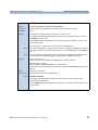
Notices
© Agilent Technologies, Inc. 2002-2005
This document contains proprietary
information that is protected by
copyright. All rights are reserved.
No part of this document may reproduced in (including electronic storage
and retrieval or translation into a foreign language) without prior agreement and written consent from Agilent
Technologies GmbH as governed by
United States and international
copyright laws.
Agilent Technologies Deutschland
GmbH
Herrenberger Str. 130
71034 Böblingen
Germany
Manual Part Number
08164-90B64
Edition
Fifth edition, January 2005
Agilent warrants that its software and
firmware designated by Agilent for use
with an instrument will execute its
programming instructions when
properly installed on that instrument.
Agilent does not warrant that the
operation of the instrument, software,
or firmware will be uninterrupted or
error free.
Limitation of Warranty
The foregoing warranty shall not apply
to defects resulting from improper or
inadequate maintenance by Buyer,
Buyer-supplied software or interfacing,
unauthorized modification or misuse,
operation outside of the environmental
specifications for the product, or
improper site preparation or
maintenance.
No other warranty is expressed or
implied. Agilent Technologies
specifically disclaims the implied
warranties of Merchantability and
Fitness for a Particular Purpose.
Fourth edition, April 2003
Third edition, February 2002
Exclusive Remedies
Second edition, Oktober 2001
The remedies provided herein are
Buyer's sole and exclusive remedies.
Agilent Technologies shall not be liable
for any direct, indirect, special,
incidental, or consequential damages
whether based on contract, tort, or any
other legal theory.
First edition, July 2001
Warranty
This Agilent Technologies instrument
product is warranted against defects in
material and workmanship for a period
of one year from date of shipment.
During the warranty period, Agilent
will, at its option, either repair or
replace products that prove to be
defective.
For warranty service or repair, this
product must be returned to a service
facility designated by Agilent. Buyer
shall prepay shipping charges to
Agilent and Agilent shall pay shipping
charges to return the product to Buyer.
However, Buyer shall pay all shipping
charges, duties, and taxes for products
returned to Agilent from another
country.
that its calibration measurements are
traceable to the United States National
Institute of Standards and Technology,
NIST (formerly the United States
National Bureau of Standards, NBS) to
the extent allowed by the Institutes’s
calibration facility, and to the
calibration facilities of other
International Standards Organization
members.
Assistance
Product maintenance agreements and
other customer assistance agreements
are available for Agilent Technologies
products. For any assistance contact
your nearest Agilent Technologies
Sales and Service Office.
Certification
Agilent Technologies Inc. certifies that
this product met its published
specifications at the time of shipment
from the factory.
Agilent Technologies further certifies
ISO 9001 Certification
Produced to ISO 9001 international
quality system standard as part of our
objective of continually increasing
customer satisfaction through
improved process control.
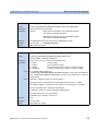
Safety Notices
CAUTION
A CAUTION notice denotes a
hazard. It calls attention to an
operating procedure, practice, or
the like that, if not correctly performed or adhered to, could result
in damage to the product or loss of
important data. Do not proceed
beyond a CAUTION notice until the
indicated conditions are fully
understood and met.
WA R N I N G
A WARNING notice denotes a
hazard. It calls attention to an
operating procedure, practice, or
the like that, if not correctly performed or adhered to, could result
in personal injury or death. Do not
proceed beyond a WARNING
notice until the indicated conditions are fully understood and met.
Warnings and Notices
WA R N I N G
To avoid the possibility of injury or death, you must observe the following
precautions before switching on the instrument.
Insert the power cable plug only into a socket outlet provided with a
protective earth contact. Do not negate this protective action by the
using an extension cord without a protective conductor.
WA R N I N G
Never look directly into the end of a fiber or a connector, unless you are
absolutely certain that there is no signal in the fiber.
Agilent Technologies Sales and Service Offices
For more information about Agilent Technologies test and measurement
products, applications, services, and for a current sales office listing, viesit
our web site:
http://www.agilent.com/comms/lightwave
You can also contact one of the following centers and ask for a test and
measurement sales representative.
United States:
1 800 829 4444
1 800 829 4433(FAX)
Canada:
1 877 894 4414
(1888 900 8921(FAX)
Europe:
(31 20) 547 2111
(31 20) 547 2190 (FAX)
Japan:
0120 421 345
0120 421 678 (FAX)
Mexico
(52 55) 5081 9469
(52 55) 5081 9467 (FAX)
Australia:
1 800 629 485
1 800 142 134 (FAX)
Asia-Pacific:
800 930 871
800 908 476 (FAX)
Brazil
(55 11) 4197 3600
(55 11) 4197 3800 (FAX)
In this Manual
This manual contains information about SCPI commands which can be
used to program the following instruments:
• Agilent 8163A/B Lightwave Multimeter
• Agilent 8164A/B Lightwave Measurement System
• Agilent 8166A/B Lightwave Multichannel System
The Structure of this Manual
This manual is divided into 5 parts:
• “Introduction to Programming” on page 15 gives a general introduction
to SCPI programming with the Agilent 8163A/B Lightwave Multimeter,
the Agilent 8164A/B Lightwave Measurement System, and the
Agilent 8166A/B Lightwave Multichannel System.
• “Specific Commands” on page 43 lists all instrument specific
commands.
• “Instrument Setup and Status” on page 55, “Measurement Operations
& Settings” on page 79, and “Mass Storage, Display, and Print
Functions” on page 185 give fuller explanations of all instrument
specific commands.
• “VISA Programming Examples” on page 189 gives some example
programs showing how the SCPI commands can be used with the
Agilent 8163A/B Lightwave Multimeter, the Agilent 8164A/B
Lightwave Measurement System, and the Agilent 8166A/B Lightwave
Multichannel System.
• “The Agilent 816x VXIplug&play Instrument Driver” on page 213, “GPIB
Command Compatibility List” on page 245, and “Error Codes” on
page 257 give information about the Agilent 816x VXIplug&play
Instrument Driver, compatibility issues, and error codes.
Conventions used in this Manual
• All commands and typed text is written in Courier font, for example
INIT[:IMM].
• SCPI commands are written in mixed case: text that you MUST print is
written in capitals; text which is helpful but nor necessary is written in
lower case.
So, the command INITiate[:IMMediate] can be entered either as
init[:imm], or as initiate[:immediate]. It does not matter whether you
enter text using capitals or lower-case letters.
• SCPI commands often contain extra arguments in square brackets.
These arguments may be helpful, but they need not be entered.
So, the command INITiate[:IMMediate] can be entered as init or
initiate:imm.
• A SCPI command which can be either a command or a query is
appended with the text /?.
So, DISPlay:ENABle/? refers to both the command DISPlay:ENABle and
the query DISPlay:ENABle?.
Related Manuals
You can find more information about the instruments covered by this
manual in the following manuals:
• Agilent 8163A/B Lightwave Multimeter, Agilent 8164A/B Lightwave
Measurement System, & Agilent 8166A/B Lightwave Multichannel
System User’s Guide (Agilent Product Number 08164-90B14).
NOTE
Please note that User Guides no longer contain programming information,
and must now be used in conjunction with this manual.
Refer to the books listed on page 16 for additional information about the
General Purpose Interface Bus, GPIB.
Table of Contents
The Structure of this Manual
Conventions used in this Manual
Related Manuals
Introduction to Programming
GPIB Interface
Returning the Instrument to Local Control
Message Queues
How the Input Queue Works
Clearing the Input Queue
The Output Queue
The Error Queue
Programming and Syntax Diagram Conventions
Short Form and Long Form
Command and Query Syntax
Units
Data Types
Slot and Channel Numbers
Laser Selection Numbers
Common Commands
Common Command Summary
Common Status Information
The Status Model
Status Registers
Status System for 8163A/B & 8164A/B
Status System for 8166A/B
Annotations
Status Byte Register
Standard Event Status Register
Operation/Questionable Status Summary
Operation/Questionable Status Summary Register
Operation/Questionable Slot Status
Operation Slot Status Register
Questionable Slot Status Register
Status Command Summary
Other Commands
Agilent 8163A/B, 8164A/B, & 8166A/B Programming Guide, Fourth Edition
5
5
6
15
16
18
19
20
20
21
22
23
24
25
25
26
26
27
29
30
31
33
33
35
36
37
37
37
37
38
38
38
38
40
41
7
Specific Commands
43
Specific Command Summary
Instrument Setup and Status
IEEE-Common Commands
Status Reporting – The STATus Subsystem
Interface/Instrument Behaviour Settings – The SYSTem
Subsystem
Measurement Operations & Settings
Root Layer Command
Measurement Functions – The SENSe Subsystem
Agilent 81635A and Agilent 81619A- Master and Slave
Channels
Signal Generation – The SOURce Subsystem
Signal Conditioning
The INPut and OUTput commands
The table of wavelength-dependent offsets
Compatibility of the 81560A/1A/6A/7A modular
attenuator family to the 8156A attenuator
Slot Numbers
Command Semantic
Display and System Commands
IEEE Commands
Status Commands
User Calibration Data
55
56
64
76
79
80
85
85
113
148
148
159
165
165
166
167
167
168
168
Signal Routing
Triggering - The TRIGger Subsystem
169
Extended Trigger Configuration
179
182
Extended Trigger Configuration Example
Mass Storage, Display, and Print Functions
Display Operations – The DISPlay Subsystem
8
44
Agilent 8163A/B, 8164A/B, & 8166A/B Programming Guide, Fourth Edition
171
185
186
VISA Programming Examples
How to Use VISA Calls
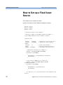
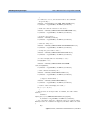
How to Set up a Fixed Laser Source
How to Measure Power using FETCh and READ
How to Co-ordinate Two Modules
How Power Varies with Wavelength
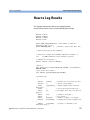
How to Log Results
The Agilent 816x VXIplug&play Instrument Driver
Installing the Agilent 816x Instrument Driver
Using Visual Programming Environments
Getting Started with Agilent VEE
GPIB Interfacing in Agilent VEE
Getting Started with LabView
Getting Started with LabWindows
Features of the Agilent 816x Instrument Driver
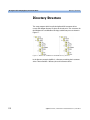
Directory Structure
Opening an Instrument Session
Closing an Instrument Session
VISA Data Types and Selected Constant Definitions
Error Handling
Introduction to Programming
Example Programs
VISA-Specific Information
189
190
192
195
199
203
207
213
214
218
218
218
221
224
225
226
227
228
229
230
232
232
Instrument Addresses
Callbacks
232
232
232
Development Environments
232
Microsoft Visual C++ 4.0 (or higher) and Borland C++ 4.5
(or higher)
Microsoft Visual Basic 4.0 (or higher)
Agilent VEE 5.01 (or higher)
LabWindows CVI/ (R) 4.0 (or higher)
Online Information
Lambda Scan Applications
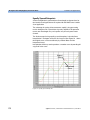
Equally Spaced Datapoints
Agilent 8163A/B, 8164A/B, & 8166A/B Programming Guide, Fourth Edition
232
233
233
233
234
235
236
9
How to Perform a Lambda Scan Application
The Prepare Lambda Scan Function
The Get Lambda Scan Parameters Function
The Execute Lambda Scan Function
How to Perform a Multi-Frame Lambda Scan Application
The Equally Spaced Datapoints Function
The Register Mainframe Function
The Unregister Mainframe Function
The Prepare Multi Frame Lambda Scan Function
The Get MF Lambda Scan Parameters Function
The Execute Multi Frame Lambda Scan Function
The Get Lambda Scan Result Function
The Get Number of PWM Channels Function
The Get Channel Location Function
GPIB Command Compatibility List
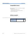
Compatibility Issues
GPIB Bus Compatibility
Status Model
Preset Defaults
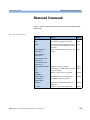
Removed Command
Obsolete Commands
Changed Parameter Syntax and Semantics
Changed Query Result Values
Timing Behavior
Error Handling
Command Order
Instrument Status Settings
Error Codes
239
240
240
240
241
242
242
242
243
243
245
246
246
247
248
249
250
251
252
253
254
255
256
257
GPIB Error Strings
Index
10
237
237
238
238
258
271
Agilent 8163A/B, 8164A/B, & 8166A/B Programming Guide, Fourth Edition
List of Figures
Figure 1
Figure 2
Figure 3
Figure 4
Figure 5
Figure 6
Figure 7
Figure 8
Figure 9
Figure 10
Figure 11
Figure 12
Figure 13
Figure 14
Figure 15
Figure 16
Figure 17
Figure 18
Figure 19
Figure 20
Remote Control . . . . . . . . . . . . . . . . . . . . . . . . . . . . . . . . . . . . . . . . . . . . . 18
The Event Status Bit . . . . . . . . . . . . . . . . . . . . . . . . . . . . . . . . . . . . . . . . . 31
The Registers and Filters for a Node . . . . . . . . . . . . . . . . . . . . . . . . . . . 33
The Operational/Questionable Status System for
8163A/B & 8164A/B . . . . . . . . . . . . . . . . . . . . . . . . . . . . . . . . . . . . . . . . 35
The Operational/Questionable Status System for 8166A/B . . . . . . . 36
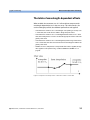
Extrapolation and interpolation of attenuator module λ offset
table . . . . . . . . . . . . . . . . . . . . . . . . . . . . . . . . . . . . . . . . . . . . . . . . . . . . . 159
Extended Trigger Configuration . . . . . . . . . . . . . . . . . . . . . . . . . . . . . . 180
Setup for Extended Trigger Configuration Example . . . . . . . . . . . . . 182
Non-Administrator Installation Pop-Up Box . . . . . . . . . . . . . . . . . . . . 215
Welcome Screen . . . . . . . . . . . . . . . . . . . . . . . . . . . . . . . . . . . . . . . . . . . 215
Customizing Your Setup . . . . . . . . . . . . . . . . . . . . . . . . . . . . . . . . . . . . 216
Program Folder Item Options . . . . . . . . . . . . . . . . . . . . . . . . . . . . . . . . 217
Device Configuration . . . . . . . . . . . . . . . . . . . . . . . . . . . . . . . . . . . . . . . 219
Advanced Device Configuration - Plug&play Driver . . . . . . . . . . . . . 219
Search for GPIB Instruments . . . . . . . . . . . . . . . . . . . . . . . . . . . . . . . . 221
FP Conversion Options Box . . . . . . . . . . . . . . . . . . . . . . . . . . . . . . . . . . 222
Windows 95 and Windows NT VXIPNP Directory Structure . . . . . . 226
Equally Spaced Datapoints . . . . . . . . . . . . . . . . . . . . . . . . . . . . . . . . . . 236
Lambda Scan Operation Setup . . . . . . . . . . . . . . . . . . . . . . . . . . . . . . . 237
Multi Frame Lambda Scan Operation Setup . . . . . . . . . . . . . . . . . . . . 239
Agilent 8163A/B, 8164A/B & 8166A/B Mainframes, Sixth Edition
11
12
Agilent 8163A/B, 8164A/B & 8166A/B Mainframes, Sixth Edition
List of Tables
Table 1
Table 2
Table 3
Table 4
Table 5
Table 6
Table 7
Table 8
Table 9
Table 10
Table 11
Table 12
Table 13
Table 14
Table 15
Table 16
Table 17
Table 18
Table 19
GPIB Capabilities . . . . . . . . . . . . . . . . . . . . . . . . . . . . . . . . . . . . . . . . . . . 17
Units and allowed Mnemonics . . . . . . . . . . . . . . . . . . . . . . . . . . . . . . . . 25
Common Command Summary . . . . . . . . . . . . . . . . . . . . . . . . . . . . . . . . 30
Specific Command Summary . . . . . . . . . . . . . . . . . . . . . . . . . . . . . . . . . 44
Commands that can only be configured using the master channel . 85
Commands that are independent for both master and slave
channels . . . . . . . . . . . . . . . . . . . . . . . . . . . . . . . . . . . . . . . . . . . . . . . . . . . 86
Comparison of command semantics beween 8156A attenuator
and 8156xA modular attenuator family. . . . . . . . . . . . . . . . . . . . . . . .166
Triggering and Power Measurements . . . . . . . . . . . . . . . . . . . . . . . . .171
Generating Output Triggers from Power Measurements . . . . . . . . .172
Incompatible GPIB Bus Commands . . . . . . . . . . . . . . . . . . . . . . . . . . .246
Removed Commands . . . . . . . . . . . . . . . . . . . . . . . . . . . . . . . . . . . . . . .249
Obsolete Commands . . . . . . . . . . . . . . . . . . . . . . . . . . . . . . . . . . . . . . .250
Commands with Different Parameters or Syntax . . . . . . . . . . . . . . .251
Queries with Different Result Values . . . . . . . . . . . . . . . . . . . . . . . . .252
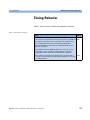
Timing Behavior Changes . . . . . . . . . . . . . . . . . . . . . . . . . . . . . . . . . . .253
Error Handling Changes . . . . . . . . . . . . . . . . . . . . . . . . . . . . . . . . . . . . .254
Specific Errors . . . . . . . . . . . . . . . . . . . . . . . . . . . . . . . . . . . . . . . . . . . . .254
Overview for Supported Strings . . . . . . . . . . . . . . . . . . . . . . . . . . . . . .258
Overview for Unsupported Strings . . . . . . . . . . . . . . . . . . . . . . . . . . . .270
Agilent 8163A/B, 8164A/B & 8166A/B Mainframes, Sixth Edition
13
14
Agilent 8163A/B, 8164A/B & 8166A/B Mainframes, Sixth Edition
1
Introduction to Programming
This chapter gives general information on how to control your instrument
remotely.
Descriptions for the actual commands for the instruments are given in the
following chapters. The information in these chapters is specific to the
Agilent 8163A/B Lightwave Multimeter, Agilent 8164A/B Lightwave
Measurement System, and Agilent 8166A/B Lightwave Multichannel
System and assumes that you are already familiar with programming the
GPIB.
GPIB Interface . . . . . . . . . . . . . . . . . . . . . . . . . . . . . . . . . . . -16
Setting the GPIB Address . . . . . . . . . . . . . . . . . . . . . . . . . . . . . . -17
Returning the Instrument to Local Control . . . . . . . . . . . . . . . . -18
Message Queues . . . . . . . . . . . . . . . . . . . . . . . . . . . . . . . . . -19
How the Input Queue Works. . . . . . . . . . . . . . . . . . . . . . . . . . . . -20
The Output Queue. . . . . . . . . . . . . . . . . . . . . . . . . . . . . . . . . . . . . -21
The Error Queue . . . . . . . . . . . . . . . . . . . . . . . . . . . . . . . . . . . . . . -22
Programming and Syntax Diagram Conventions. . . . . . . -23
Short Form and Long Form . . . . . . . . . . . . . . . . . . . . . . . . . . . . . -24
Command and Query Syntax . . . . . . . . . . . . . . . . . . . . . . . . . . . . -25
Common Commands . . . . . . . . . . . . . . . . . . . . . . . . . . . . . . -29
Common Command Summary . . . . . . . . . . . . . . . . . . . . . . . . . . -30
Common Status Information . . . . . . . . . . . . . . . . . . . . . . . . . . . . -31
The Status Model. . . . . . . . . . . . . . . . . . . . . . . . . . . . . . . . . -33
Status Registers . . . . . . . . . . . . . . . . . . . . . . . . . . . . . . . . . . . . . . -33
Status System for 8163A/B & 8164A/B . . . . . . . . . . . . . . . . . . -35
Status System for 8166A/B . . . . . . . . . . . . . . . . . . . . . . . . . . . . -36
Annotations . . . . . . . . . . . . . . . . . . . . . . . . . . . . . . . . . . . . . . . . . . -37
Status Command Summary. . . . . . . . . . . . . . . . . . . . . . . . . . . . . -40
Other Commands . . . . . . . . . . . . . . . . . . . . . . . . . . . . . . . . . . . . . -41
Agilent 8163A/B, 8164A/B & 8166A/B Mainframes, Fifth Edition
15
Introduction to Programming
GPIB Interface
GPIB Interface
The interface used by your instrument is the GPIB (General Purpose
Interface Bus).
GPIB is the interface used for communication between a controller and an
external device, such as the tunable laser source. The GPIB conforms to
IEEE standard 488-1978, ANSI standard MC 1.1 and IEC recommendation
625-1.
If you are not familiar with the GPIB, then refer to the following books:
• The International Institute of Electrical and Electronics Engineers. IEEE
Standard 488.1-1987, IEEE Standard Digital Interface for Programmable
Instrumentation. New York, NY, 1987
• The International Institute of Electrical and Electronics Engineers. IEEE
Standard 488.2-1987, IEEE Standard Codes, Formats, Protocols and
Common Commands For Use with ANSI/IEEE Std 488.1-1987. New York,
NY, 1987
To obtain a copy of either of these last two documents, write to:
The Institute of Electrical and Electronics Engineers, Inc.
345 East 47th Street
New York, NY 10017
USA.
In addition, the commands not from the IEEE-488.2 standard, are defined
according to the Standard Commands for Programmable Instruments
(SCPI).
For information about SCPI, and SCPI programming techniques, please
refer to:
• The SCPI Consortium: Standard Commands for Programmable
Instruments. To obtain a copy of this manual, contact the following
address:
SCPI Consortium Office
Bode Enterprise
2515 Camino del Rio South, Suite 340
San Diego, CA, 92108
USA
Web: http://www.scpiconsortium.org
16
Agilent 8163A/B, 8164A/B & 8166A/B Mainframes, Fifth Edition
GPIB Interface
Introduction to Programming
The interface of the Agilent 8163A/B Lightwave Multimeter,
Agilent 8164A/B Lightwave Measurement System, and Agilent 8166A/B
Lightwave Multichannel System to the GPIB is defined by the IEEE
Standards 488.1 and 488.2.
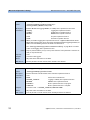
Table 1 shows the interface functional subset that the instruments
implement.
Table 1 GPIB Capabilities
Mnemonic
Function
SH1
Complete source handshake capability
AH1
Complete acceptor handshake capability
T6
Basic talker; serial poll; no talk only mode; unaddressed to talk
if addressed to listen
L4
Basic listener; no listen only mode; unaddressed to listen if addressed to talk
SR0
No service request capability
RL1
Complete remote/local capability
PP0
No parallel poll capability
DC1
Complete device clear capability
DT0
No device trigger capability
C0
No controller capability.
Setting the GPIB Address
There are two ways to set the GPIB address:
• You can set the GPIB address by using the command
“:SYSTem:COMMunicate:GPIB[:SELF]:ADDRess” on page 78.
• You can set the GPIB address from the front panel. See your
instrument’s User’s Guide for more information.
The default GPIB address is 20.
NOTE
GPIB address 21 is often applied to the GPIB controller. If so, 21 cannot be
used as an instrument address.
Agilent 8163A/B, 8164A/B & 8166A/B Mainframes, Fifth Edition
17
Introduction to Programming
GPIB Interface
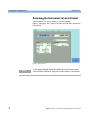
Returning the Instrument to Local Control
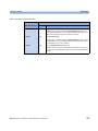
If the instrument is in remote control, a screen resembling
Figure 1 will appear. Press [Local] if you wish to return the instrument to
local control.
Figure 1 Remote Control
NOTE
18
If your Agilent 8163A/B, 8164A/B or 8166A/B is in local lockout mode
(refer to DISPlay:LOCKout on page 142) the Local softkey is not available.
Agilent 8163A/B, 8164A/B & 8166A/B Mainframes, Fifth Edition
Message Queues
Introduction to Programming
Message Queues
The instrument exchanges messages using an input and an output queue.
Error messages are kept in a separate error queue.
Agilent 8163A/B, 8164A/B & 8166A/B Mainframes, Fifth Edition
19
Introduction to Programming
Message Queues
How the Input Queue Works
The input queue is a FIFO queue (first-in first-out). Incoming bytes are
stored in the input queue as follows:
1 Receiving a byte:
• Clears the output queue.
• Clears Bit 7 (MSB).
2 No modification is made inside strings or binary blocks. Outside strings
and binary blocks, the following modifications are made:
• Lower-case characters are converted to upper-case.
• The characters 0016 to 0916 and 0B16 to 1F16 are converted to spaces
(2016).
• Two or more blanks are truncated to one.
3 An EOI (End Or Identify) sent with any character is put into the input
queue as the character followed by a line feed (LF, 0A16). If EOI is sent
with a LF, only one LF is put into the input queue.
4 The parser starts if the LF character is received or if the input queue is
full.
Clearing the Input Queue
Switching the power off, or sending a Device Interface Clear signal, causes
commands that are in the input queue, but have not been executed to be
lost.
20
Agilent 8163A/B, 8164A/B & 8166A/B Mainframes, Fifth Edition
Message Queues
Introduction to Programming
The Output Queue
The output queue contains responses to query messages. The instrument
transmits any data from the output queue when a controller addresses the
instrument as a talker.
Each response message ends with a carriage return (CR, 0D16) and a LF
(0A16), with EOI=TRUE. If no query is received, or if the query has an error,
the output queue remains empty.
The Message Available bit (MAV, bit 4) is set in the Status Byte register
whenever there is data in the output queue.
Agilent 8163A/B, 8164A/B & 8166A/B Mainframes, Fifth Edition
21
Introduction to Programming
Message Queues
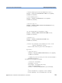
The Error Queue
The error queue is 30 errors long. It is a FIFO queue (first-in first-out). That
is, the first error read is the oldest error to have occurred. For example:
1
If no error has occurred, the error queue contains:
+ 0, "No error"
2
After a command such as wav:pow, the error queue now contains:
+ 0, "No error"
-113, "Undefined header"
3
If the command is immediately repeated, the error queue now contains:
+ 0, "No error"
-113, "Undefined header"
-113, "Undefined header"
If more than 29 errors are put into the queue, the message:
-350, "Queue overflow"
is placed as the last message in the queue.
22
Agilent 8163A/B, 8164A/B & 8166A/B Mainframes, Fifth Edition
Programming and Syntax Diagram Conventions
Introduction to Programming
Programming and Syntax
Diagram Conventions
A program message is a message containing commands or queries that
you send to the instruments. The following are a few points about program
messages:
• You can use either upper-case or lower-case characters.
• You can send several commands in a single message. Each command
must be separated from the next one by a semicolon (;).
• A command message is ended by a line feed character (LF) or
<CR><LF>.
• You can use any valid number/unit combination.
In other words, 1500NM,1.5UM and 1.5E-6M are all equivalent.
If you do not specify a unit, then the default unit is assumed. The default
unit for the commands are given with command description in the next
chapter.
Agilent 8163A/B, 8164A/B & 8166A/B Mainframes, Fifth Edition
23
Introduction to Programming
Programming and Syntax Diagram Conventions
Short Form and Long Form
The instrument accepts messages in short or long forms.
For example, the message
:STATUS:OPERATION:ENABLE 768
is in long form.
The short form of this message is
:STAT:OPER:ENAB 768
In this manual, the messages are written in a combination of upper and
lower case. Upper case characters are used for the short form of the
message.
For example, the above command would be written
:STATus:OPERation:ENABle
The first colon can be left out for the first command or query in your
message. That is, the example given above could also be sent as
STAT:OPER:ENAB 768
24
Agilent 8163A/B, 8164A/B & 8166A/B Mainframes, Fifth Edition
Programming and Syntax Diagram Conventions
Introduction to Programming
Command and Query Syntax
All characters not between angled brackets must be sent exactly as
shown.
The characters between angled brackets (<...>) indicate the kind of data
that you should send, or that you get in a response. You do not type the
angled brackets in the actual message.
Descriptions of these items follow the syntax description. The following
types of data are most commonly used:
string
is ascii data. A string is contained between double quotes ("...") or
single quotes (‘...’).
value
is numeric data in integer (12), decimal (34.5) or exponential format
(67.8E-9).
wsp
is a white space.
Other kinds of data are described as required.
The characters between square brackets ([...]) show optional information
that you can include with the message.
The bar (|) shows an either-or choice of data, for example, a|b means
either a or b, but not both simultaneously.
Extra spaces are ignored, so spaces can be inserted to improve readability.
Units
Where units are given with a command, usually only the base units are
specified. The full sets of units are given in the table below.
Table 2 Units and allowed Mnemonics
Unit
Default
Allowed Mnemonics
meters
M
PM, NM, UM, MM, M
decibel
DB
MDB, DB
second
S
NS, US, MS, S
decibel/1mW
DBM
MDBM, DBM
Hertz
HZ
HZ, KHZ, MHZ, GHZ, THZ
Watt
Watt
PW, NW, UW, MW, Watt
meters per second
M/S
NM/S, UM/S, MM/S, M/S
Agilent 8163A/B, 8164A/B & 8166A/B Mainframes, Fifth Edition
25
Introduction to Programming
Programming and Syntax Diagram Conventions
Data Types
With the commands you give parameters to the instrument and receive
response values from the instrument. Unless explicitly specified these
data are given in ASCII format. The following types of data are used:
• Boolean data may only have the values 0 or 1.
• Integer range is given for each individual command.
• Float variables may be given in decimal or exponential writing (0.123 or
123E-3).
All Float values conform to the 32 bit IEEE Standard, that is, all Float
values are returned as 32-bit real values.
• A string is contained between double quotes ("...") or single quotes
(‘...’). When the instrument returns a string, it is always included in " "
and terminated by <END>.
• When a register value is given or returned (for example *ESE), the
decimal values for the single bits are added. For example, a value of
nine means that bit 0 and bit 3 are set.
• Larger blocks of data are given as Binary Blocks, preceded by
“#<H><Len><Block>”, terminated by <END>; <H> represents the
number of digits, <Len> represents the number of bytes, and <Block> is
the data block. For example, for a Binary Block with 1 digit and 6 bytes
this is: #16TRACES<END>.
Slot and Channel Numbers
Each module is identified by a slot number and a channel number. For
commands that require you to specify a channel, the slot number is
represented by [n] in a command and the channel number is represented
by [m].
The slot number represents the module’s position in the mainframe. These
are:
• from one to two for the Agilent 8163A/B,
• from zero to four for the Agilent 8164A/B, and
• from one to seventeen for the Agilent 8166A/B.
These numbers are displayed on the front panel beside each module slot.
26
Agilent 8163A/B, 8164A/B & 8166A/B Mainframes, Fifth Edition
Programming and Syntax Diagram Conventions
NOTE
Introduction to Programming
The Agilent 8164A/B slot for a back-loadable tunable laser module is
numbered zero.
Channel numbers apply to modules that have two inputs/outputs, for
example, the Agilent 81635A Dual Power Sensor.
Modules with two channels, for example, the Agilent 81635A Dual Power
Sensor, use the channel number to distinguish between these channels.
NOTE
The channel number of single channel modules is always one.
For example, if you want to query slot 1, channel 2 with the command,
“:SENSe[n]:[CHANnel[m]]:POWer:WAVelength?” on page 109, you should
send the command:
• :sens1:chan2:pow:wav?
NOTE
If you do not specify a slot or channel number, the lowest possible number
is used as the default value. This means:
• Slot 1 for the Agilent 8163A/B and Agilent 8166A/B mainframes.
• Slot 0 for the Agilent 8164A/B mainframe.
• Channel 1 for all channels.
Laser Selection Numbers
The laser selection number, [l], identifies the upper or lower wavelength
laser source for dual wavelength Laser Source modules and Return Loss
modules with two internal laser sources. The lower wavelength source is
denoted by 1. The upper wavelength source is denoted by 2.
Agilent 8163A/B, 8164A/B & 8166A/B Mainframes, Fifth Edition
27
Introduction to Programming
NOTE
Programming and Syntax Diagram Conventions
For Return Loss modules, 0 denotes the use of an external laser source as
the input to your Return Loss module for the following commands:
• “:SENSe[n]:[CHANnel[m]]:RETurnloss:CORRection:FPDelta[l]” on
page 111,
• “:SENSe[n]:[CHANnel[m]]:RETurnloss:CORRection:FPDelta[l]?” on
page 111,
• “:SENSe[n]:[CHANnel[m]]:RETurnloss:CORRection:REFLectance[l]” on
page 112, and
• “:SENSe[n]:[CHANnel[m]]:RETurnloss:CORRection:FPDelta[l]” on
page 111.
28
Agilent 8163A/B, 8164A/B & 8166A/B Mainframes, Fifth Edition
Common Commands
Introduction to Programming
Common Commands
The IEEE 488.2 standard has a list of reserved commands, called common
commands. Some of these commands must be implemented by any
instrument using the standard, others are optional.
Your instrument implements all the necessary commands, and some
optional ones. This section describes the implemented commands.
Agilent 8163A/B, 8164A/B & 8166A/B Mainframes, Fifth Edition
29
Introduction to Programming
Common Commands
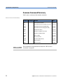
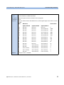
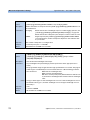
Common Command Summary
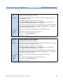
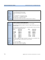
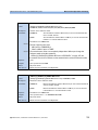
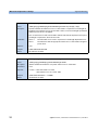
Table 3 gives a summary of the common commands.
Table 3 Common Command Summary
NOTE
30
Command Parameter
Function
Page
*CLS
Clear Status Command
page 57
*ESE
Standard Event Status Enable Command
page 57
*ESE?
Standard Event Status Enable Query
page 58
*ESR?
Standard Event Status Register Query
page 58
*IDN?
Identification Query
page 59
*OPC
Operation Complete Command
page 59
*OPC?
Operation Complete Query
page 60
*OPT?
Options Query
page 60
*RST
Reset Command
page 61
*STB?
Read Status Byte Query
page 61
*TST?
Self Test Query
page 62
*WAI
Wait Command
page 63
These commands are described in more detail in “IEEE-Common
Commands” on page 56.
Agilent 8163A/B, 8164A/B & 8166A/B Mainframes, Fifth Edition
Common Commands
Introduction to Programming
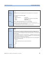
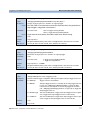
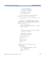
Common Status Information
There are three registers for the status information. Two of these are
status-registers and one is an enable-registers. These registers conform to
the IEEE Standard 488.2-1987. You can find further descriptions of these
registers under *ESE, *ESR?, and *STB?.
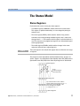
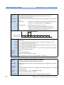
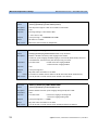
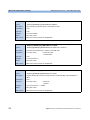
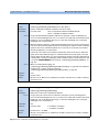
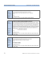
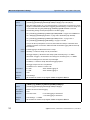
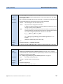
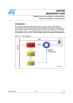
Figure 2 shows how the Standard Event Status Enable Mask (SESEM)
and the Standard Event Status Register (SESR) determine the Event Status
Bit (ESB) of the Status Byte.
*ESE sets the Standard Event Status Enable Mask
*STB? returns the Status Byte Register
OSB ESB MAV QSB
7 6 5 4 3 2
Status
0
1 0 0
Byte
1
Event
Status
Enable
Mask
7
1
6
5
1
4
1
3
1
2
1
1
0
1
&
0
&
&
OR
&
&
&
&
All bits shown as
are unused
&
Event
Status
Register
7
0
6
5
0
4
0
3
0
2
0
1
0
1
*ESR? returns the Standard Event Status Register
Figure 2 The Event Status Bit
The SESR contains the information about events that are not slot specific.
For details of the function of each bit of the SESR, see “Standard Event
Status Register” on page 37.
The SESEM allows you to choose the event that may affect the ESB of the
Status Byte. If you set a bit of the SESEM to zero, the corresponding event
cannot affect the ESB. The default is for all the bits of the SESEM to be set
to 0.
The questionable and operation status systems set the Operational Status
Bit (OSB) and the Questionable Status Bit (QSB). These status systems
are described in “The Status Model” on page 33 and “Status Reporting –
The STATus Subsystem” on page 64.
Agilent 8163A/B, 8164A/B & 8166A/B Mainframes, Fifth Edition
31
Introduction to Programming
NOTE
32
Common Commands
Unused bits in any of the registers change to 0 when you read them.
Agilent 8163A/B, 8164A/B & 8166A/B Mainframes, Fifth Edition
The Status Model
Introduction to Programming
The Status Model
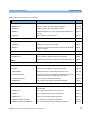
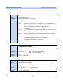
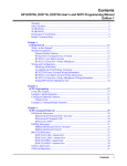
Status Registers
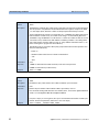
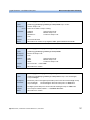
Each node of the status circuitry has three registers:
• A condition register (CONDition), which contains the current status.
This register is updated continuously. It is not changed by having its
contents read.
• The event register (EVENt), which contains details of any positive
transitions in the corresponding condition register, that is, when a bit
changes from 0 → 1. The contents of this register are cleared when it is
read. The contents of any higher-level registers are affected with regard
to the appropriate bit.
• The enable register (ENABle), which enables changes in the event
register to affect the next stage of registers.
NOTE
The event register is the only kind of register that can affect the next stage
of registers.
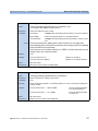
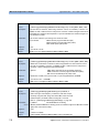
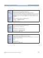
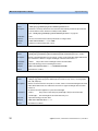
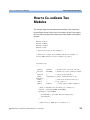
The structures of the Operational and Questionable Status Systems are
similar. Figure 4 describe how the Questionable Status Bit (QSB) and the
Operational Status Bit (OSB) of the Status Byte Register are determined.
Enable Registers
OR
To the
Condition Register
of the Next Node
Event Registers
1 1 1 1 1
A positive transition in the condition
register, when a bit changes from 0 → 1,
causes the corresponding bit of the
corresponding event register
to change from 0 → 1.
Condition Registers
Figure 3 The Registers and Filters for a Node
Agilent 8163A/B, 8164A/B & 8166A/B Mainframes, Fifth Edition
33
Introduction to Programming
The Status Model
The Operational/Questionable Slot Status Event Register (OSSER/QSSER)
contains the status of a particular module slot. A bit changes from 0 → 1
when an event occurs, for example, when a laser is switched on. For
details of the function of each bit of these registers, see
“Operation/Questionable Status Summary Register” on page 38.
The Operational/Questionable Slot Enable Status Mask (OSESM/QSESM)
allows you to choose the events for each module slot that may affect the
Operational/Questionable Status Event Register (see below). If you set a
bit of the OSESM/QSESM to zero, the occurence of the corresponding
event for this particular module slot cannot affect the
Operational/Questionable Status Event Register. The default is for all the
bits of the OSESM/QSESM to be set to 0.
The Operational/Questionable Status Event Summary Register
(OSESR/QSESR) summarizes the status of every module slot of your
instrument. If, for any slot, any bit of the QSSER goes from 0 → 1 AND the
corresponding bit of the QSSEM is 1 at the same time, the QSESR bit
representing that slot is set to 1.
The Operational/Questionable Status Enable Summary Mask
(OSESM/QSESM) allows you to choose the module slots that may affect
the OSB/QSB of the Status Byte. If any bit of the QSESR goes from 0 → 1
AND the corresponding bit of the QSESM is 1 at the same time, the QSB of
the Status Byte is set to 1. If you set a bit of the OSESM/QSESM to zero,
the corresponding module slot cannot affect the OSB/QSB. The default is
for all the bits of the OSESM/QSESM to be set to 0.
The Operational/Questionable Status Enable Summary Mask for the
Agilent 8163A/B Lightwave Multimeter and the Agilent 8164A/B
Lightwave Measurement System consists of one level. These are
described in “Status System for 8163A/B & 8164A/B” on page 35.
As the Agilent 8166A/B Lightwave Multichannel System has 17 module
slots, the Operational/Questionable Status Enable Summary Mask
consists of two levels. This is described in “Status System for 8166A/B”
on page 36.
34
Agilent 8163A/B, 8164A/B & 8166A/B Mainframes, Fifth Edition
The Status Model
Introduction to Programming
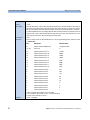
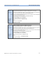
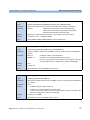
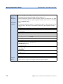
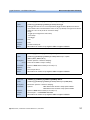
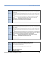
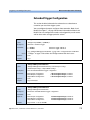
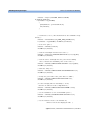
Status System for 8163A/B & 8164A/B
The status system for the Agilent 8163A/B Lightwave Multimeter and the
Agilent 8164A/B Lightwave Measurement System returns the status of 2
and 5 module slots respectively. The Operational/Questionable Status
Summary Registers consist of one level and are described by Figure 4 .
Any commands that require LEVel1 do not apply to these mainframes.
Status Byte Register
Status Summary
Status Byte
Operational/Questionable Status
Enable Summary Mask
Register
&
Operational/Questionable Status
Event Summary Register
Operational/Questionable
Slot Status Enable Mask
Register
Operational/Questionable
Slot Status Event
Register
Operational/Questionable
Slot Status Condition
Register
&
&
&
OR
&
for a positive
transition
Operational/Questionable Status
Condition Summary Register
Slot 1
to next
level
to next
level
&
&
OR
&
for a positive
transition
Figure 4 The Operational/Questionable Status System for 8163A/B & 8164A/B
Agilent 8163A/B, 8164A/B & 8166A/B Mainframes, Fifth Edition
35
Introduction to Programming
The Status Model
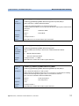
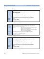
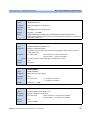
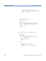
Status System for 8166A/B
The status system for the Agilent 8166A/B Lightwave Multichannel
System returns the status of 17 module slots. The
Operational/Questionable Status Summary Registers consists of two
levels, as described by Figure 5 .
Module slots 1 to 14 affect the Level 0 summary register as described in
Figure 4 . Bit 0 of the Level 0 summary registers represents the summary
of the status of module slots 15, 16, and 17. The Level 1 summary registers
contain an individual summary for each of these module slots.
Status Byte Register
Status
Summary
for Level 0
Status Byte
Operational/Questionable Status
Enable Summary Mask
Register (Level 0)
&
to next
level
&
Operational/Questionable Status
Event Summary Register (Level 0)
Operational/Questionable Status
Enable Summary Mask
Register (Level 1)
&
Operational/Questionable Status
Event Summary Register (Level 1)
to next
level
&
&
OR
&
for a positive
transition
Operational/Questionable Status
Condition Summary Register (Level 1)
Slot 15
Operational/Questionable
Slot Status Enable Mask
Register
Operational/Questionable
Slot Status Event
Register
Operational/Questionable
Slot Status Condition
Register
&
OR
&
for a positive
transition
Operational/Questionable Status
Condition Summary Register (Level 0)
Status
Summary
for Level 1
&
to next
level
&
&
OR
&
for a positive
transition
Figure 5 The Operational/Questionable Status System for 8166A/B
36
Agilent 8163A/B, 8164A/B & 8166A/B Mainframes, Fifth Edition
The Status Model
Introduction to Programming
Annotations
Status Byte Register
• Bit 3, the QSB, is built from the questionable event status register and
its enable mask.
• Bit 4, the MAV, is set if the message output queue is not empty.
• Bit 5, the ESB, is built from the SESR and its SESEM.
• Bit 7, the OSB, is built from the operation event status register and its
enable mask.
• All other bits are unused, and therefore set to 0.
Standard Event Status Register
• Bit 0 is set if an operation complete event has been received since the
last call to *ESR?.
• Bit 1 is always 0 (no service request).
• Bit 2 is set if a query error has been detected.
• Bit 3 is set if a device dependent error has been detected.
• Bit 4 is set if an execution error has been detected.
• Bit 5 is set if a command error has been detected.
• Bit 6 is always 0 (no service request).
• Bit 7 is set for the first call of *ESR? after Power On.
Operation/Questionable Status Summary
• The Operation/Questionable Status Summary consist of a condition and
an event register.
• A "rising" bit in the condition register is copied to the event register.
• A "falling" bit in the condition register has no effect on the event
register.
• Reading the condition register is non-destructive.
• Reading the event register is destructive.
• A summary of the event register and its enable mask is set in the status
byte.
Agilent 8163A/B, 8164A/B & 8166A/B Mainframes, Fifth Edition
37
Introduction to Programming
The Status Model
Operation/Questionable Status Summary Register
• Bits 0 to 4 are built from the OSSER/QSSER and the OSSEM/QSSEM.
• A summary of the event register, the condition register and the enable
mask is set in the status byte.
Operation/Questionable Slot Status
• The Operation/Questionable Slot Status consist of a condition and an
event register.
• A "rising" bit in the condition register is copied to the event register.
• A "falling" bit in the condition register has no effect on the event
register.
• Reading the condition register is non-destructive.
• Reading the event register is destructive.
• A summary of the event register, the condition register and the enable
mask is set in the status byte.
Operation Slot Status Register
• Bit 0 is set if the laser is switched on.
• Bit 1 is set if the Coherence Control is switched on.
• Bit 3 is set if Power Meter zeroing or Tunable Laser module lambda
zeroing is ongoing.
• Bit 4 is set if the attenuator output is enabled (shutter open).
• Bits 5 - 7 are set if the wavelength offset table is enabled (see page 68).
• All other bits are unused, and therefore set to 0.
Questionable Slot Status Register
• Bit 0 is set if excessive power is set by the user for any source module
or if excessive averaging time is set for any Power Meter.
• Bit 1 is set if the last Power Meter zeroing failed.
• Bit 2 is set if temperature is out of range.
• Bit 3 is set if laser protection is switched on.
38
Agilent 8163A/B, 8164A/B & 8166A/B Mainframes, Fifth Edition
The Status Model
Introduction to Programming
• Bit 4 is set if the module has not settled, as during the automatic
settling of a Tunable Laser module.
• Bit 5 is set if the module is out of specifications, or if lambda zeroing
failed for a Tunable Laser module.
• Bit 6 is set if ARA is recommended.
• Bit 7 is set if the duty cycle is out of range.
• Bit 8 is set if coherence control is uncalibrated
• Bit 9 is set if attenuator beam path protection is enabled (shutter is
closed)
• Bit 10 is set if lambda zeroing is recommended.
• All other bits are unused, and therefore set to 0.
Agilent 8163A/B, 8164A/B & 8166A/B Mainframes, Fifth Edition
39
Introduction to Programming
The Status Model
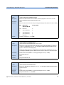
Status Command Summary
40
*STB?
returns status byte, value 0 .. +255
*ESE
sets the standard event status enable mask, parameter 0 .. +255
*ESE?
returns SESE, value 0 .. +255
*ESR?
returns the standard event status register, value 0 .. +255
*OPC
parses all program message units in the message queue, and prevents
the instrument from executing any further commands until all pending
commands are completed.
*OPC?
returns 1 if all operations (scan trace printout, measurement) are completed. Otherwise it returns 0.
*CLS
clears the status byte and SESR, and removes any entries from the error queue.
*RST
clears the error queue, loads the default setting, and restarts communication.
NOTE: *RST does NOT touch the STB or SESR. A running measurement
is stopped.
*TST?
initiates an instrument selftest and returns the results as a 32 bit
LONG.
Agilent 8163A/B, 8164A/B & 8166A/B Mainframes, Fifth Edition
The Status Model
Introduction to Programming
Other Commands
*OPT?
returns the installed modules and the slots these modules are installed
in:
For example, *OPT? → 81682A, 81533B, 81532A, ,
Modules 81682A, 81533B, and 81532A are installed in slots 0 to 2 respectively. Slots 3 and 4 are empty.
*WAI
prevents the instrument from executing any further commands until the
current command has finished executing. All pending operations are
completed during the wait period.
*IDN?
identifies the instrument; returns the manufacturer, instrument model
number, serial number, and firmware revision level.
Agilent 8163A/B, 8164A/B & 8166A/B Mainframes, Fifth Edition
41
Introduction to Programming
42
The Status Model
Agilent 8163A/B, 8164A/B & 8166A/B Mainframes, Fifth Edition
2
Specific Commands
This chapter lists all the instrument specific commands relating to the
Agilent 8163A/B Lightwave Multimeter, the Agilent 8164A/B Lightwave
Measurement System, and the Agilent 8166A/B Lightwave Multichannel
System with a single-line description.
Each of these summaries contains a page reference for more detailed
information about the particular command later in this manual.
Specific Command Summary . . . . . . . . . . . . . . . . . . . . . . . -44
Agilent 8163A/B, 8164A/B & 8166A/B Mainframes, Fifth Edition
43
Specific Commands
Specific Command Summary
Specific Command Summary
The commands are ordered in a command tree. Every command belongs to
a node in this tree.
The root nodes are also called the subsystems. A subsystem contains all
commands belonging to a specific topic. In a subsystem there may be
further subnodes.
All the nodes have to be given with a command. For example in the
command disp:brig
• DISPlay is the subsystem containing all commands for controlling the
display,
• BRIGhtness is the command selecting brightness.
NOTE
If a command and a query are both available, the command ends /?.
So, disp:brig/? means that disp:brig and disp:brig? are both available.
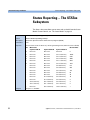
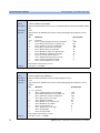
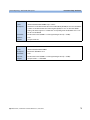
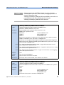
Table 4 gives an overview of the command tree. You see the nodes, the
subnodes, and the included commands.
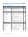
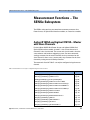
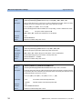
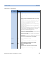
Table 4 Specific Command Summary
Command
Description
Page
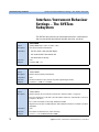
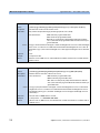
:WAVelength:REFerence/?
Sets or queries the slot and channel of the external reference
powermeter.
page 161
:WAVelength:STATe/?
Switches or queries attenuator Offset Table on or off/?
page 160
:WAVelength:TABle?
Queries the complete offset table.
page 164
:WAVelength:TABle:SIZE?
Queries the size of the offset table.
page 164
:WAVelength:VALue
Adds a value pair (wavelength, offset) to the offset table.
page 161
:WAVelength:VALue:DELete
Deletes an offset value pair.
page 163
:WAVelength:VALue:DELete:ALL
Deletes all value pairs from the offset table.
page 163
:WAVelength:VALue:OFFSet?
Queries an offset value according to wavelength or index.
page 162
:WAVelength:VALue:PAIR?
Queries an offset/wavelength value pair according to wavelength page 163
or index.
:WAVelength:VALue:WAVelength?
Queries a wavelength value from its index in the offset table
:CONFigure[n][:CHANnel[m]]:OFFSet
44
page 162
Agilent 8163A/B, 8164A/B & 8166A/B Mainframes, Fifth Edition
Specific Command Summary
Specific Commands
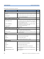
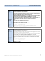
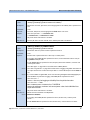
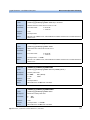
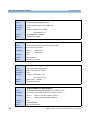
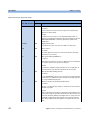
Table 4 Specific Command Summary (continued)
Command
Description
Page
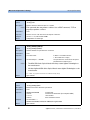
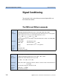
:BRIGhtness/?
Controls or queries the current display brightness.
page 186
:CONTrast/?
Controls or queries the current display contrast.
page 186
:ENABle/?
Switches the display on or off, or queries whether the display is
on or off.
page 187
:LOCKout/?
Sets or queries local lockout mode.
page 187
:POWer[:DC]?
Returns a power value from a sensor.
page 87
:RETurnloss?
Returns the current return loss value.
page 87
:MONitor?
Returns the current power value from the monitor diode within a page 88
return loss module.
:DISPlay
:FETCh[n][:CHANnel[m]][:SCALar]
:INITiate[n]:[CHANnel[m]]
[:IMMediate]
Starts a measurement.
page 88
:CONTinuous/?
Starts or Queries a single/continuous measurement.
page 89
:LOCK/?
Switches the lock on/off or returns the current state of the lock. page 80
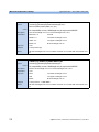
:INPUT[n][:CHANnel[m]]
:ATTenuation/?
Sets or returns the attenuation factor for the instrument.
page 148
:OFFset/?
Sets or returns the offset factor for the instrument.
page 149
:OFFset:DISPlay
Sets the offset factor so that attenuation factor is zero.
page 149
:OFFset:POWermeter
Sets the offset factor to the difference between the power measured with a powermeter and with the monitor diode.
page 150
:ATTenuation:SPEed/?
Sets or queries the filter transition speed
page 150
:WAVelength/?
Sets or queries the modules attenuation wavelength
page 151
:APMode/?
Sets or queries whether power setting or attenuation value has
been changed.
page 151
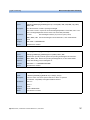
:APOWeron/?
Sets or queries the shutter status at power on.
page 157
:ATIMe/?
Sets or queries the powermeter averaging time.
page 157
:CONNection/?
Selects or returns Analog Output parameter.
page 113
:CORRection:COLLection:ZERO
Zeros the offsets of attenuators powermeter
page 157
:CORRection:COLLection:ZERO:ALL
Zeros all available powermeter channels in mainframe
page 158
:OUTPut[n][:CHANnel[m]]
Agilent 8163A/B, 8164A/B & 8166A/B Mainframes, Fifth Edition
45
Specific Commands
Specific Command Summary
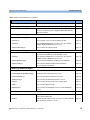
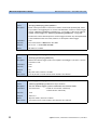
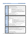
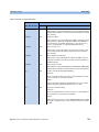
Table 4 Specific Command Summary (continued)
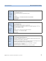
Command
Description
Page
:CORRection:COLLection:ZERO?
Queries the status of the last zero operation
page 158
:PATH/?
Sets or returns the regulated path.
page 113
:POWer/?
Sets or queries the output power value.
page 152
:POWer:CONTRol/?
Sets or queries power control mode status
page 155
:POWer:OFFSet/?
Sets or queries the power offset value.
page 154
:POWer:OFFSet:POWermeter
Calculates power offset from measured power values
page 154
:POWer:REFerence/?
Sets or queries the reference power value.
page 153
:POWer:REFerence:POWermeter
Copies power value from power meter to attenuator module ref.
power parameter
page 153
:POWer:UNit/?
Sets or queries power unit used (dBm or W)
page 155
[:STATe]/?
Sets a source’s or attenuators output terminals to open or closed page 114
or returns the current status of a source’s or attenuators output
terminals.
:READ[n][:CHANnel[m]]
[:SCALar]:POWer[:DC]?
Reads the current power value from a sensor.
page 89
:POWer[:DC]:ALL?
Reads all available power meter channels.
page 90
:POWer[:DC]:ALL:CONFig?
Return all the slot and channel number of every available power
meter channel.
page 90
[:SCALar]:RETurnloss?
Reads the current return loss value.
page 91
[:SCALar]:MONitor?
Returns the current power value from the monitor diode within a page 91
return loss module.
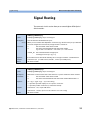
:ROUTe[n]
46
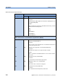
[:CHANnel[m]]/?
Sets or returns the channel route between two ports.
page 169
[:CHANnel[m]]:CONFig?
Reads the switch configuration of an instrument.
page 170
[:CHANnel[m]]:CONFig:ROUTe?
Reads the allowed switch routes of an instrument.
page 170
Agilent 8163A/B, 8164A/B & 8166A/B Mainframes, Fifth Edition
Specific Command Summary
Specific Commands
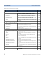
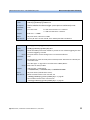
Table 4 Specific Command Summary (continued)
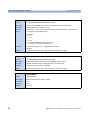
Command
Description
Page
[:LOSS][:INPut][:MAGNitude]/?
Sets or returns the value of correction data for a sensor.
page 92
:COLLECT:ZERO
Executes a zero calibration of a sensor module.
page 92
:COLLECT:ZERO?
Returns the current zero state of a sensor module.
page 93
:COLLECT:ZERO:ALL
Executes a zero calibration of all sensor modules.
page 93
:PARameter:LOGGing/?
Sets or returns the number of samples and the averaging time,
tavg, for logging.
page 94
:PARameter:MINMax/?
Sets or returns the minmax mode and the window size.
page 95
:PARameter:STABility/?
Sets or returns the total time, delay time and the averaging time, page 96
tavg, for stability.
:RESult?
Returns the data array of the last function.
page 97
:RESult:BLOCk?
Returns a specified binary block from the data array for the last
power meter data acquisition function.
page 98
:RESult:MAXBlocksize?
Returns the maximum block size for power meter data acquisition page 98
functions.
:RESult:MONitor?
For return loss module, returns monitor diode data array of last
function.
:STATe/?
Enables/disables the function mode or returns whether the func- page 100
tion mode is enabled.
:THReshold/?
Sets or returns the threshold value and the start mode.
page 101
:ATIMe/?
Sets or returns the average time of a sensor.
page 101
:RANGe[:UPPer]/?
Sets or returns the most positive signal entry expected for a sen- page 102
sor.
:RANGe:MONitor[:UPPer]/?
Sets or returns the range of the monitor diode within a return loss page 103
module.
:RANGe:AUTO/?
Sets or returns the range of a sensor to produce the most dynam- page 104
ic range without overloading.
:REFerence/?
Sets or returns the reference level of a sensor.
:UNIT/?
Sets or returns the units used for absolute readings on a sensor. page 108
:WAVelength/?
Sets or returns the wavelength for a sensor.
:SENSe[n][:CHANnel[m]]:CORRection
:SENSe[n][:CHANnel[m]]:FUNCtion
page 99
:SENSe[n][:CHANnel[m]]:POWer
Agilent 8163A/B, 8164A/B & 8166A/B Mainframes, Fifth Edition
page 105
page 108
47
Specific Commands
Specific Command Summary
Table 4 Specific Command Summary (continued)
Command
Description
Page
:SENSe[n][:CHANnel[m]]:POWer:Reference
:DISPlay
Sets the reference level for a sensor from the input power level.
page 106
:STATe/?
Sets or returns whether sensor results are in relative or absolute page 106
units.
:STATe:RATio/?
Sets or returns whether sensor results are displayed relative to a page 106
channel or to an absolute reference.
:SENSe[n][:CHANnel[m]]:RETurnloss:CALibration
:FACTory
Sets the calibration value to factory settings.
page 109
:COLLect:REFLectance
Sets the reference reflectance calibration values to the values
page 109
currently measured by the chosen return loss module. (When, for
example, a gold reflector is used.)
:COLLect:TERMination
Sets the termination calibration values to the values currently
measured by the chosen return loss module.
page 110
:COLLect:VALues?
Returns current calibration values.
page 110
:TERMination?
Returns T-Value
page 110
:SENSe[n][:CHANnel[m]]:RETurnloss:CORRection
:FPDelta[l]/?
Sets or returns front panel delta, that is, the loss correction value page 111
due, for example, to the front panel connector.
:REFLectance[l]/?
Sets or returns the return loss reference, the return loss value of page 112
your reference reflector.
:SLOT[n]
:EMPTy?
Returns whether the module slot is empty.
page 81
:IDN?
Returns information about the module.
page 81
:OPTions?
Returns the module’s options.
page 81
:TST?
Returns the latest selftest results for a module.
page 82
:EMPTy?
Returns whether an optical head is connected.
page 82
:IDN?
Returns information about the optical head.
page 82
:OPTions?
Returns the optical head’s options.
page 83
:TST?
Returns the latest selftest results for an optical head.
page 83
:WAVelength:RESPonse?
Returns the wavelength response from the module with wavelength calibration.
page 83
:WAVelength:RESPonse:CSV?
Returns the wavelength response from the module with wavelength calibration.
page 84
:SLOT[n][:HEAD[m]]
48
Agilent 8163A/B, 8164A/B & 8166A/B Mainframes, Fifth Edition
Specific Command Summary
Specific Commands
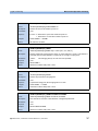
Table 4 Specific Command Summary (continued)
Command
Description
Page
:WAVelength:RESPonse:SIZE?
Returns the no. of elements in the wavelength response table.
page 84
Returns the mode of the modulation output mode of the BNC
connector on the front panel of Agilent 81640A/80A/82A Tunable Laser modules.
page 121
[:INTernal]:FREQuency[l]/?
Sets or returns the frequency of an internal signal source.
page 115
:SOURce[l]/?
Sets or returns a source for the modulating system.
page 116
:STATe[l]/?
Turns Amplitude Modulation of a source on or off or queries
whether Amplitude Modulation is on or off.
page 117
:COHCtrl:COHLevel[l]/?
Sets or returns the coherence level.
page 118
:SOURce[l]/?
Sets or returns the type of frequency modulaion employed, specifically Simulated Brillouin Scattering (SBS) control.
page 118
:STATe[l]/?
Turns Frequency Modulation of a source on or off or queries
whether Frequency Modulation is on or off.
page 119
:SBSCtrl:FREQuency[l]/?
Sets or returns the frequency of SBS Control modulation.
page 120
:SBSCtrl:LEVel[l]/?
Sets or returns the level of SBS Control modulation
(as a percentage of maximum)
page 120
[:LEVel][:IMMediate][:AMPLitude[l]]
Sets the laser output power of a source.
page 124
[:LEVel][:IMMediate][:AMPLitude[l]]?
Returns the laser output power of a source.
page 125
[:LEVel]:RISetime[l]/?
Sets or returns the laser rise time of a source.
page 126
:ATTenuation[l]/?
Sets or returns the attenuation level for a source.
page 122
:STATe/?
Sets or returns the state of the source output signal.
page 127
:UNIT/?
Sets or returns the power units.
page 127
:WAVelength/?
Sets or returns the wavelength source of a dual-wavelength
source.
page 128
[:SOURce[n]][:CHANnel[m]]
:MODout/?
[:SOURce[n]][:CHANnel[m]]:AM
[:SOURce[n]][:CHANnel[m]]:FM
[:SOURce[n]][:CHANnel[m]:]POWer
[:SOURce[n]][:CHANnel[m]:]POWer:ATTenuation[l]
:AUTO/?
Selects Automatic or Manual Attenuation Mode for a source or
returns the selected mode.
:DARK/?
Enables/disables ‘dark’ position on a source or returns whether page 123
‘dark’ position is active for a source.
Agilent 8163A/B, 8164A/B & 8166A/B Mainframes, Fifth Edition
page 123
49
Specific Commands
Specific Command Summary
Table 4 Specific Command Summary (continued)
Command
Description
Page
:DATA?
Returns number of datapoints returned by the
[:SOURce[n]][:CHANnel[m]]:READout:POINts? command.
page 129
:DATA:BLOCk?
Returns a specified binary block from either a lambda logging op- page 129
eration, or maximum power at wavelength characteristic.
:DATA:MAXBlocksize?
Returns the maximum blocksize that a lambda logging, or maximum power at wavelength characteristic will return.
:POINts?
Returns the data as a binary stream from either a lambda logging page 130
operation or the maximum power the laser can produce at each
wavelength.
[:SOURce[n]][:CHANnel[m]:]READout
page 129
[:SOURce[n]][:CHANnel[m]:]WAVelength
[:CW[l]:FIXED]
Sets the absolute wavelength of a source.
page 130
[:CW[l]:FIXED[l]]?
Returns the absolute wavelength of a source.
page 131
:FREQuency[l]/?
Sets the frequency difference used to calculate a relative wavelength for a source.
page 134
:REFerence[l]?
Returns the reference wavelength of a source.
page 135
[:SOURce[n]][:CHANnel[m]:]WAVelength:CORRection
:ARA
Realigns the laser cavity.
page 131
:ARA:ALL
Realigns the laser cavity of every tunable laser source in the
mainframe.
page 132
:AUTocalib
Sets or returns tunable laser source Auto Calibration state.
page 132
:ZERO
Executes a wavelength zero.
page 132
:ZERO:ALL
Executes a wavelength zero on every tunable laser source in the page 133
mainframe.
:ZERO:TEMPerature:ACTual?
Reports the current lambda zero temperature
page 133
:ZERO:TEMPerature:DIFFerence?
Reports the temperature difference required to trigger an auto
lamda zero.
page 134
:ZERO:TEMPerature:LASTzero?
Reports the temperature at which the last auto lamda zero took
place.
page 134
:ZERO:AUTO
Forces an auto lamda zero. This is quicker than the equilavent
manual process.
page 134
[:SOURce[n]][:CHANnel[m]:]WAVelength:REFerence
:DISPlay
50
Sets the reference wavelength of a source to the value of the out- page 135
put wavelength.
Agilent 8163A/B, 8164A/B & 8166A/B Mainframes, Fifth Edition
Specific Command Summary
Specific Commands
Table 4 Specific Command Summary (continued)
Command
Description
Page
[:SOURce[n]][:CHANnel[m]:]WAVelength:SWEep
:CHECkparams?
Returns whether sweep parameters set are consistent.
page 136
:CYCLes/?
Sets or returns the number of cycles.
page 137
:DWELl/?
Sets or returns the dwell time.
page 138
:EXPectedtriggers?
Returns number of triggers (used to configure power meter).
page 138
:FLAG?
Returns whether waiting for trigger, or logging data available.
page 139
:LLOGging/?
Switches lambda logging on or off or queries the state of lambda page 140
logging.
:MODE/?
Sets or returns the sweep mode.
page 141
:PMAX?
Returns the highest permissible power for a wavelength sweep.
page 141
:REPeat/?
Sets or returns the repeat mode.
page 142
:SOFTtrigger
Sends a soft trigger.
page 143
:SPEed/?
Sets or returns the speed for continuous sweeping.
page 143
:STARt/?
Sets or returns the start point of the sweep.
page 144
:STOP/?
Sets or returns the end point of the sweep.
page 144
[:STATe]/?
Stops, starts, pauses or continues a wavelength sweep or returns page 145
the the state of a sweep.
[:SOURce[n]][:CHANnel[m]:]WAVelength:SWEep:STEP
:NEXT
Performs the next sweep step.
page 146
:PREVious
Performs the previous sweep step again.
page 146
[:WIDTh]/?
Sets or returns the width of the sweep step.
page 146
Agilent 8163A/B, 8164A/B & 8166A/B Mainframes, Fifth Edition
51
Specific Commands
Specific Command Summary
Table 4 Specific Command Summary (continued)
Command
Description
Page
Reboots the mainframe and all modules.
page 84
Presets all Enable Registers.
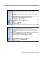
page 69
:SPECial
:REBoot
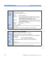
:STATus[n]
:PRESet
:STATus:OPERation
[:EVENt]?
Returns the Operational Status Event Summary Register (OESR). page 68
[:EVENt]:LEVel1?
Returns the Operational Status Event Summary Register for slots page 66
15 - 17 of the Agilent 8166A/B Lightwave Multichannel System.
:CONDition?
Returns the Operational Status Condition Summary Register.
:CONDition:LEVel1?
Returns the Operational Status Condition Summary Register for page 67
slots 15 - 17 of the Agilent 8166A/B Lightwave Multichannel System.
:ENABle/?
Sets or queries the Operational Status Enable Summary Mask.
:ENABle:LEVel1/?
Sets or queries the Operational Status Enable Summary Mask for page 67
slots 15 - 17 of the Agilent 8166A/B Lightwave Multichannel System.
page 68
page 69
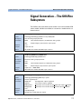
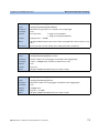
:STATusn:OPERation
[:EVENt]?
Returns the Operational Slot Status Event Register for slot n.
:CONDition?
Returns the Operational Slot Status Condition Register for slot n. page 68
:ENABle/?
Sets or queries the Operation Slot Status Enable Mask for slot n. page 69
page 68
:STATus:QUEStionable
52
[:EVENt]?
Returns the Questionable Status Event Summary Register.
page 74
[:EVENt]:LEVel1?
page 72
Returns the Questionable Status Event Summary Register for
slots 15 - 17 of the Agilent 8166A/B Lightwave Multichannel System.
:CONDition?
Returns the Questionable Status Condition Summary Register.
:CONDition:LEVel1?
Returns the Questionable Status Condition Summary Register for page 73
slots 15 - 17 of the Agilent 8166A/B Lightwave Multichannel System.
:ENABle/?
Sets or queries the Questionable Status Enable Summary Mask.
:ENABle:LEVel1/?
Sets or queries the Questionable Status Enable Summary Mask page 73
for slots 15 - 17 of the Agilent 8166A/B Lightwave Multichannel
System.
page 74
page 75
Agilent 8163A/B, 8164A/B & 8166A/B Mainframes, Fifth Edition
Specific Command Summary
Specific Commands
Table 4 Specific Command Summary (continued)
Command
Description
Page
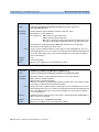
[:EVENt]?
Returns the Questionable Slot Status Event Register for slot n.
page 74
:CONDition?
Returns the Questionable Slot Status Condition Register for slot
n.
page 74
:ENABle/?
Sets or queries the Questionable Slot Status Enable Mask for page 75
slot n.
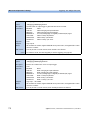
:STATusn:QUEStionable
:SYSTem
:DATE/?
Sets or returns the instrument’s internal date.
page 76
:ERRor?
Returns the contents of the instrument’s error queue.
page 76
:HELP:HEADers?
Returns a list of GPIB commands.
page 77
:PRESet
Sets all parameters to their default values.
page 77
:TIME/?
Sets or returns the instrument’s internal time.
page 77
:VERSion?
Returns the instrument’s SCPI version.
page 78
Sets or returns the GPIB address.
page 78
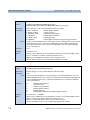
Generates a hardware trigger.
page 172,
page 179
Sets or returns trigger configuration.
page 177
:EXTended/?
Sets or returns extended trigger configuration.
page 179
:FPEDal/?
Enables/disables the Input Trigger connector to be triggered us- page 178
ing a Foot Pedal or returns whether the Input Trigger connector
can be triggered using a Foot Pedal.
:SYSTem:COMMunicate:GPIB
[:SELF]:ADDress/?
:TRIGger
:CONFiguration/?
:TRIGger:CONFiguration
:TRIGger[n][CHANnel[m]]
:INPut/?
Sets or returns the incoming trigger response .
page 173
:OFFset/?
Sets or returns the number of incoming triggers received before
data logging begins
page 175
:INPut:REARm/?
Re-arms input trigger
page 174
:OUTPut/?
Sets or returns the outgoing trigger response.
page 176
:OUTPut:REARm/?
Re-arms output trigger
page 177
Agilent 8163A/B, 8164A/B & 8166A/B Mainframes, Fifth Edition
53
Specific Commands
54
Specific Command Summary
Agilent 8163A/B, 8164A/B & 8166A/B Mainframes, Fifth Edition
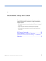
3
Instrument Setup and Status
This chapter gives descriptions of commands that you can use when
setting up your instrument. The commands are split into the following
separate subsytems:
• IEEE specific commands that were introduced in “Common Commands”
on page 29.
• STATus subsystem commands that relate to the status model.
• SYSTem subsystem commands that control the serial interface and
internal data.
IEEE-Common Commands . . . . . . . . . . . . . . . . . . . . . . . . . . 56
Status Reporting – The STATus Subsystem. . . . . . . . . . . . 64
Interface/Instrument Behaviour Settings – The SYSTem
Subsystem. . . . . . . . . . . . . . . . . . . . . . . . . . . . . . . . . . . . . . . . 76
Agilent 8163A/B, 8164A/B & 8166A/B Mainframes, Fifth Edition
55
Instrument Setup and Status
IEEE-Common Commands
IEEE-Common Commands
“Common Commands” on page 29 gave a brief introduction to the IEEEcommon commands which can be used with the instruments. This section
gives fuller descriptions of each of these commands.
56
Agilent 8163A/B, 8164A/B & 8166A/B Mainframes, Fifth Edition
IEEE-Common Commands
Instrument Setup and Status
command:
*CLS
syntax:
*CLS
description:
The CLear Status command *CLS clears the following:
• Error queue
• Standard event status register (SESR)
• Status byte register (STB)
After the *CLS command the instrument is left waiting for the next command. The instrument setting is unaltered by the command, although *OPC/*OPC? actions are cancelled.
parameters:
none
response:
none
example:
*CLS
command:
*ESE
syntax:
*ESE<wsp><value>
0 ≤ value ≤ 255
description:
The standard Event Status Enable command (*ESE) sets bits in the Standard Event Status
Enable Mask (SESEM) that enable the corresponding bits in the standard event status register (SESR).
The register is cleared:
• at power-on,
• by sending a value of zero.
The register is not changed by the *RST and *CLS commands.
parameters:
The bit value for the register (a 16-bit signed integer value):
Bit
Mnemonic
Decimal Value
7 (MSB)
Power On
128
6
Not Used
0
5
Command Error
32
4
Execution Error
16
3
Device Dependent Error
8
2
Query Error
4
1
Not Used
0
0 (LSB)
Operation Complete
1
response:
none
example:
*ESE 21
Agilent 8163A/B, 8164A/B & 8166A/B Mainframes, Fifth Edition
57
Instrument Setup and Status
command:
*ESE?
syntax:
*ESE?
description:
The standard Event Status Enable query *ESE? returns the contents of the Standard Event
Status Enable Mask (see *ESE for information on this register).
parameters:
none
response:
The bit value for the register (a 16-bit signed integer value).
example:
*ESE? → 21<END>
command:
*ESR?
syntax:
*ESR?
description:
The standard Event Status Register query *ESR? returns the contents of the Standard
Event Status Register. The register is cleared after being read.
parameters
none
response
The bit value for the register (a 16-bit signed integer value):
example:
58
IEEE-Common Commands
Bit
Mnemonic
Decimal Value
7 (MSB)
Power On
128
6
Not used
0
5
Command Error
32
4
Execution Error
16
3
Device Dependent Error
8
2
Query Error
4
1
Not used
0
0 (LSB)
Operation Complete
1
*ESR? → 21<END>
Agilent 8163A/B, 8164A/B & 8166A/B Mainframes, Fifth Edition
IEEE-Common Commands
Instrument Setup and Status
command:
*IDN?
syntax:
*IDN?
description:
The IDeNtification query *IDN? gets the instrument identification over the interface.
parameters:
none
response:
The identification terminated by <END>:
For example.
Agilent Technologies
mmmm
ssssssss
rrrrrrrrrr
example:
NOTE
manufacturer
instrument model number (for example 8164B)
serial number
firmware revision level
*IDN? → Agilent Techologies,mmmm,ssssssss,rrrrrrrrrr<END>
The Agilent 8163A, Agilent 8164A, and Agilent8166A will always return Agilent Technologies as the
manufacturer. This will not be affected by the transition of these instruments to Agilent Technologies. This will
allow programs that use this string to continue functioning.
See “:SLOT[n]:HEAD[n]:IDN?” on page 82 for information on module identity strings.
command:
*OPC
syntax:
*OPC
description:
The instrument parses and executes all program message units in the input queue and
sets the operation complete bit in the standard event status register (SESR). This command can be used to avoid filling the input queue before the previous commands have finished executing.
Some module firmware includes commands that set a "StatNOPC" flag during execution
to indicate that the module is busy. *OPC blocks the GPIB bus to all commands until every
module hosted by the instrument is no longer busy.
The following actions cancel the *OPC command (and put the instrument into Operation
Complete, Command Idle State):
• Power-on
• the Device Clear Active State is asserted on the interface.
• *CLS
• *RST
parameters:
none
response:
none
example:
*OPC
Agilent 8163A/B, 8164A/B & 8166A/B Mainframes, Fifth Edition
59
Instrument Setup and Status
IEEE-Common Commands
command:
*OPC?
syntax:
*OPC?
description:
The OPeration Complete query *OPC? parses all program message units in the input queue,
sets the operation complete bit in the Standard Event Status register, and places an ASCII
’1’ in the output queue, when the contents of the input queue have been processed.
Some module firmware includes commands that set a "StatNOPC" flag during execution to
indicate that the module is busy. If a module is executing a command which generates a
"StatNOPC" flag, the GPIB bus is not blocked to a command to another module. A second
command to a busy module is blocked until the module flag "StatOK" is set. Taking advantage of this feature, and using *OPC? in a loop to query until the instrument returns 1, can
lead to useful gains in program execution efficiency.
The following actions cancel the *OPC? query (and put the instrument into Operation Complete, Command Idle State):
• Power-on
• the Device Clear Active State is asserted on the interface.
• *CLS
• *RST
parameters:
none
response:
1<END> is returned if all modules are ready to execute a new operation.
0<END> is returned if any module is busy.
example:
*OPC? → 1<END>
command:
*OPT?
syntax:
*OPT?
description:
The OPTions query *OPT? returns the modules installed in your instrument.
parameters:
none
response:
Returns the part number of all installed modules, separated by commas.
Slots are listed starting with the lowest slot number, that is, slot 0 for the Agilent 8164A/B
and Slot 1 for the Agilent 8163A/B and Agilent 8166A/B.
If any slot is empty or not recognised, two spaces are inserted instead of the module’s part
number. See the example below, where slots 1 and 4 are empty.
example:
60
*OPT? → 81682A , , 81533B, 81532A, <END>
Agilent 8163A/B, 8164A/B & 8166A/B Mainframes, Fifth Edition
IEEE-Common Commands
Instrument Setup and Status
command:
*RST
syntax:
*RST
description:
The ReSeT command *RST sets the mainframe and all modules to the reset setting (standard setting) stored internally.
Pending *OPC? actions are cancelled.
The instrument is placed in the idle state awaiting a command. The *RST command clears
the error queue.
The *RST command is equivalent to the *CLS command AND the syst:preset command.
The following are not changed:
• GPIB (interface) state
• Instrument interface address
• Output queue
• Service request enable register (SRE)
• Standard Event Status Enable Mask (SESEM)
parameters:
none
response:
none
example:
*RST
command:
*STB?
syntax:
*STB?
description:
The STatus Byte query *STB? returns the contents of the Status Byte register.
parameters:
none
response:
The bit value for the register (a 16-bit signed integer value):
example:
Bit
Mnemonic
Decimal Value
7 (MSB)
Operation Status (OSB)
128
6
Not used
0
5
Event Status Bit (ESB)
32
4
Message Available (MAV)
16
3
Questionable Status (QSB)
8
2
Not used
0
1
Not used
0
0
Not used
0
*STB? → 128<END>
Agilent 8163A/B, 8164A/B & 8166A/B Mainframes, Fifth Edition
61
Instrument Setup and Status
IEEE-Common Commands
command:
*TST?
syntax:
*TST?
description:
The self-TeST query *TST? makes the instrument perform a self-test and place the results of
the test in the output queue. If the self-test fails, the results are also put in the error queue.
We recommend that you read self-test results from the error queue. No further commands
are allowed while the test is running. After the self-test the instrument is returned to the setting that was active at the time the self-test query was processed. The self-test does not require operator interaction beyond sending the *TST? query.
parameters:
none
response:
The sum of the results for the individual tests (a 32-bit signed integer value, where 0 ≤ value
≤ 4294967296):
Bits
Mnemonic
Decimal Value
31
Selftest failed on Mainframe
A negative value
18 - 30
Not used
0
17
Selftest failed on Slot 17
131072
16
Selftest failed on Slot 16
65536
15
Selftest failed on Slot 15
32768
14
Selftest failed on Slot 14
16384
13
Selftest failed on Slot 13
8192
12
Selftest failed on Slot 12
4096
11
Selftest failed on Slot 11
2048
10
Selftest failed on Slot 10
1024
9
Selftest failed on Slot 9
512
8
Selftest failed on Slot 8
256
7
Selftest failed on Slot 7
128
6
Selftest failed on Slot 6
64
5
Selftest failed on Slot 5
32
4
Selftest failed on Slot 4
16
3
Selftest failed on Slot 3
8
2
Selftest failed on Slot 2
4
1
Selftest failed on Slot 1
2
0
Selftest failed on Slot 0
1
If 16 is returned, the module in slot 4 has failed.
If 18 is returned, the modules in slots 1 and 4 have failed.
A value of zero indicates no errors.
example:
62
*TST? → 0<END>
Agilent 8163A/B, 8164A/B & 8166A/B Mainframes, Fifth Edition
IEEE-Common Commands
Instrument Setup and Status
command:
*WAI
syntax:
*WAI
description:
The WAIt command prevents the instrument from executing any further commands until the
current command has finished executing. Some module firmware includes commands that
set a "StatNOPC" flag during execution to indicate that the module is busy. *WAI blocks the
GPIB bus to all commands until every module hosted by the instrument is no longer busy. All
pending operations, are completed during the wait period.
parameters:
none
response:
none
example:
*WAI
Agilent 8163A/B, 8164A/B & 8166A/B Mainframes, Fifth Edition
63
Instrument Setup and Status
Status Reporting – The STATus Subsystem
Status Reporting – The STATus
Subsystem
The Status subsystem allows you to return and set details from the Status
Model. For more details, see “The Status Model” on page 33.
command:
:STATus:OPERation[:EVENt][:LEVel0]?
syntax:
:STATus:OPERation[:EVENt][:LEVel0]?
description:
Returns the Operational Status Event Summary Register (OSESR).
parameters:
none
response:
The sum of the results for the slots (a 16-bit signed integer value, where 0 ≤ value ≤ 32767):
Bits
example:
64
Mnemonics
Decimal Value
Agilent 8163A/B
Agilent 8164A/B
Agilent 8166A/B
15
Not used
Not used
Not used
0
14
Not used
Not used
Slot 14 Summary
16384
13
Not used
Not used
Slot 13 Summary
8192
12
Not used
Not used
Slot 12 Summary
4096
11
Not used
Not used
Slot 11 Summary
2048
10
Not used
Not used
Slot 10 Summary
1024
9
Not used
Not used
Slot 9 Summary
512
8
Not used
Not used
Slot 8 Summary
256
7
Not used
Not used
Slot 7 Summary
128
6
Not used
Not used
Slot 6 Summary
64
5
Not used
Not used
Slot 5 Summary
32
4
Not used
Slot 4 Summary
Slot 4 Summary
16
3
Not used
Slot 3 Summary
Slot 3 Summary
8
2
Slot 2 Summary
Slot 2 Summary
Slot 2 Summary
4
1
Slot 1 Summary
Slot 1 Summary
Slot 1 Summary
2
0
Not used
Slot 0 Summary
Level 1 Summary
1
stat:oper? → +0<END>
Agilent 8163A/B, 8164A/B & 8166A/B Mainframes, Fifth Edition
Status Reporting – The STATus Subsystem
Instrument Setup and Status
command:
:STATus:OPERation:CONDition[:LEVel0]?
syntax:
:STATus:OPERation:CONDition[:LEVel0]?
description:
Reads the Operational Status Condition Summary Register.
parameters:
none
response:
The sum of the results for the individual slots (a 16-bit signed integer value, where 0 ≤ value ≤
32767):
Bits
example:
Mnemonics
Decimal Value
Agilent 8163A/B
Agilent 8164A/B
Agilent 8166A/B
15
Not used
Not used
Not used
0
14
Not used
Not used
Slot 14 Summary
16384
13
Not used
Not used
Slot 13 Summary
8192
12
Not used
Not used
Slot 12 Summary
4096
11
Not used
Not used
Slot 11 Summary
2048
10
Not used
Not used
Slot 10 Summary
1024
9
Not used
Not used
Slot 9 Summary
512
8
Not used
Not used
Slot 8 Summary
256
7
Not used
Not used
Slot 7 Summary
128
6
Not used
Not used
Slot 6 Summary
64
5
Not used
Not used
Slot 5 Summary
32
4
Not used
Slot 4 Summary
Slot 4 Summary
16
3
Not used
Slot 3 Summary
Slot 3 Summary
8
2
Slot 2 Summary
Slot 2 Summary
Slot 2 Summary
4
1
Slot 1 Summary
Slot 1 Summary
Slot 1 Summary
2
0
Not used
Slot 0 Summary
Level 1 Summary
1
stat:oper:cond? → +0<END>
Agilent 8163A/B, 8164A/B & 8166A/B Mainframes, Fifth Edition
65
Instrument Setup and Status
Status Reporting – The STATus Subsystem
command:
:STATus:OPERation:ENABle[:LEVel0]
syntax:
:STATus:OPERation:ENABle[:LEVel0]<wsp><value>
description:
Sets the bits in the Operational Status Enable Summary Mask (OSESM) that enable the contents of the OSESR to affect the Status Byte (STB).
Setting a bit in this register to 1 enables the corresponding bit in the OSESR to affect bit 7 of
the Status Byte.
The bit value for the OSESM as a 16-bit signed integer value (0 .. +32767)
parameters:
The default value is 0.
response:
none
example:
stat:oper:enab 128
command:
:STATus:OPERation:ENABle[:LEVel0]?
syntax:
:STATus:OPERation:ENABle[:LEVel0]?
description:
Returns the OSESM for the OSESR
parameters:
none
response:
The bit value for the operation enable mask as a 16-bit signed integer value (0 .. +32767)
example:
stat:oper:enab? → +128<END>
command:
:STATus:OPERation[:EVENt]:LEVel1?
syntax:
:STATus:OPERation[:EVENt]:LEVel1?
description:
Returns the Operational Status Event Summary Register (OSESR) for slots 15 to 17 of the
Agilent 8166A/B Lightwave Multichannel System.
parameters:
none
response:
The sum of the results for the slots (a 16-bit signed integer value, where 0 ≤ value ≤ 32767):
Bits
Mnemonics
Decimal Value
Agilent 8166A/B
example:
66
15-4
Not used
0
3
Slot 17 Summary
8
2
Slot 16 Summary
4
1
Slot 15 Summary
2
0
Not used
0
stat:oper:level1? → +0<END>
Agilent 8163A/B, 8164A/B & 8166A/B Mainframes, Fifth Edition
Status Reporting – The STATus Subsystem
Instrument Setup and Status
command:
:STATus:OPERation:CONDition:LEVel1?
syntax:
:STATus:OPERation:CONDition:LEVel1?
description:
Returns the Operational Status Condition Summary Register for slots 15 to 17 of the
Agilent 8166B Lightwave Multichannel System.
parameters:
none
response:
The sum of the results for slots 15 to 17 (a 16-bit signed integer value, where 0 ≤ value ≤
32767):
Bits
Mnemonics
Decimal Value
Agilent 8166A/B
15-4
Not used
0
3
Slot 17 Summary
8
2
Slot 16 Summary
4
1
Slot 15 Summary
2
0
Not used
0
example:
stat:oper:cond:level1? → +0<END>
command:
:STATus:OPERation:ENABle:LEVel1
syntax:
:STATus:OPERation:ENABle:LEVel1<wsp><value>
description:
Sets the bits in the Operational Status Enable Summary Mask (OSESM) that enable the contents of the OSESR for slots 15 - 17 of the Agilent 8166A/B Lightwave Measurement System
to affect the Status Byte (STB).
Setting a bit in this register to 1 enables the corresponding bit in the OSESR for slots 15 - 17 of
the Agilent 8166A/B Lightwave Measurement System to affect bit 7 of the Status Byte.
parameters:
The bit value for the OSESM as a 16-bit signed integer value (0 .. +32767)
The default value is 0.
response:
none
example:
stat:oper:enab:level1 128
command:
:STATus:OPERation:ENABle:LEVel1?
syntax:
:STATus:OPERation:ENABle:LEVel1?
description:
Returns the OSESM for the OSESR for slots 15 - 17 of the Agilent 8166A/B Lightwave Measurement System
parameters:
none
response:
The bit value for the operation enable mask as a 16-bit signed integer value (0 .. +32767)
example:
stat:oper:enab:level1? → +128<END>
Agilent 8163A/B, 8164A/B & 8166A/B Mainframes, Fifth Edition
67
Instrument Setup and Status
Status Reporting – The STATus Subsystem
command:
:STATusn:OPERation[:EVENt]?
syntax:
:STATusn:OPERation[:EVENt]?
description:
Returns the Operational Slot Status Event Register (OSSER) of slot n.
parameters:
none
response:
The results for the individual slot events (a 16-bit signed integer value, where 0 ≤ value ≤
32767):
Bit
Mnemonic
Decimal Value
8-15
Not used
0
7
6
5
4
3
2
1
0
Slot n: offset (λ) type bit 2
Slot n: offset (λ) type bit 1
Slot n: offset (λ) has been enabled
Slot n: shutter has been opened
Slot n: Zeroing ongoing
Not used
Slot n: Coherence Control has been switched on
Slot n: Laser has been switched on
128
64
32
16
8
0
2
1
example:
stat1:oper? → +0<END>
command:
:STATusn:OPERation:CONDition?
syntax:
:STATusn:OPERation:CONDition?
description:
Returns the Operational Slot Status Condition Register of slot n.
parameters:
none
response:
The results for the individual slot events (a 16-bit signed integer value, where 0 ≤ value ≤
32767):
example:
Bit
Mnemonic
Decimal Value
8-15
Not used
0
7
6
5
4
3
2
1
0
Slot n: offset (λ) type bit 2
Slot n: offset (λ) type bit 1
Slot n: offset (λ) enabled
Slot n: shutter open
Slot n: Zeroing ongoing
Not used
Slot n: Coherence Control is switched on
Slot n: Laser is switched on
128
64
32
16
8
0
2
1
stat1:oper:cond? → +0<END>
NOTE:
68
Only attenuator bits 5 to 7 are used to show whether the offset feature is
used and which algorithm is used to calculate the wavelength dependent
offset.
Bit 5 states if the feature is enabled or disabled. Bits 6 and 7 are decoded as
shown below to say whether the attenuator uses saved, interpolated, or
extrapolated values.
Agilent 8163A/B, 8164A/B & 8166A/B Mainframes, Fifth Edition
Status Reporting – The STATus Subsystem
Instrument Setup and Status
Type
Bit 5
Bit 6
Bit 7
Decimal Value
none
0
0
0
0
exact value
1
0
0
32
extrapolate below
1
1
0
96
extrapolate above
1
0
1
160
interpolated
1
1
1
224
command:
:STATusn:OPERation:ENABle
syntax:
:STATusn:OPERation:ENABle<wsp><value>
description:
Sets the bits in the Operation Slot Status Enable Mask (OSSEM) for slot n that enable the
contents of the Operation Slot Status Event Register (OSSER) for slot n to affect the OSESR.
Setting a bit in this register to 1 enables the corresponding bit in the OSSER for slot n to affect bit n of the OSESR.
parameters:
The bit value for the OSSEM as a 16-bit signed integer value (0 .. +32767)
response:
none
example:
stat:oper:enab 128
command:
:STATusn:OPERation:ENABle?
syntax:
:STATusn:OPERation:ENABle?
description:
Returns the OSSEM of slot n
parameters:
none
response:
The bit value for the OSSEM as a 16-bit signed integer value (0 .. +32767)
example:
stat:oper:enab? → +128<END>
command:
:STATus:PRESet
syntax:
:STATus:PRESet
description:
Presets all bits in all the enable masks for both the OPERation and QUEStionable status systems to 0, that is, OSSEM, QSSEM, OSESM, and QSESM.
parameters:
none
response:
none
example:
stat:pres
Agilent 8163A/B, 8164A/B & 8166A/B Mainframes, Fifth Edition
69
Instrument Setup and Status
Status Reporting – The STATus Subsystem
command:
:STATus:QUEStionable[:EVENt][:LEVel0]?
syntax:
:STATus:QUEStionable[:EVENt][:LEVel0]?
description:
Returns the Questionable Status Event Summary Register (QSESR).
parameters:
none
response:
The sum of the results for the QSESR as a 16-bit signed integer value (0 .. +32767)
Bits Mnemonics
example:
70
Decimal Value
Agilent 8163A/B
Agilent 8164A/B
Agilent 8166A/B
15
Not used
Not used
Not used
14
Not used
Not used
Slot 14 Summary 16384
13
Not used
Not used
Slot 13 Summary 8192
12
Not used
Not used
Slot 12 Summary 4096
11
Not used
Not used
Slot 11 Summary 2048
10
Not used
Not used
Slot 10 Summary 1024
9
Not used
Not used
Slot 9 Summary
512
8
Not used
Not used
Slot 8 Summary
256
7
Not used
Not used
Slot 7 Summary
128
6
Not used
Not used
Slot 6 Summary
64
5
Not used
Not used
Slot 5 Summary
32
4
Not used
Slot 4 Summary
Slot 4 Summary
16
3
Not used
Slot 3 Summary
Slot 3 Summary
8
2
Slot 2 Summary
Slot 2 Summary
Slot 2 Summary
4
1
Slot 1 Summary
Slot 1 Summary
Slot 1 Summary
2
0
Not used
Slot 0 Summary
Level 1 Summary 1
0
stat:ques? → +0<END>
Agilent 8163A/B, 8164A/B & 8166A/B Mainframes, Fifth Edition
Status Reporting – The STATus Subsystem
Instrument Setup and Status
command:
:STATus:QUEStionable:CONDition[:LEVel0]?
syntax:
:STATus:QUEStionable:CONDition[:LEVel0]?
description:
Returns the Questionable Status Condition Summary Register.
parameters:
none
response:
The sum of the results for the Questionable Status Condition Summary Register as a 16-bit
signed integer value (0 .. +32767)
Bits Mnemonics
example:
Decimal Value
Agilent 8163A/B
Agilent 8164A/B
Agilent 8166A/B
15
Not used
Not used
Not used
0
14
Not used
Not used
Slot 14 Summary
16384
13
Not used
Not used
Slot 13 Summary
8192
12
Not used
Not used
Slot 12 Summary
4096
11
Not used
Not used
Slot 11 Summary
2048
10
Not used
Not used
Slot 10 Summary
1024
9
Not used
Not used
Slot 9 Summary
512
8
Not used
Not used
Slot 8 Summary
256
7
Not used
Not used
Slot 7 Summary
128
6
Not used
Not used
Slot 6 Summary
64
5
Not used
Not used
Slot 5 Summary
32
4
Not used
Slot 4 Summary
Slot 4 Summary
16
3
Not used
Slot 3 Summary
Slot 3 Summary
8
2
Slot 2 Summary
Slot 2 Summary
Slot 2 Summary
4
1
Slot 1 Summary
Slot 1 Summary
Slot 1 Summary
2
0
Not used
Slot 0 Summary
Level 1 Summary
1
stat:ques:cond? → +0<END>
Agilent 8163A/B, 8164A/B & 8166A/B Mainframes, Fifth Edition
71
Instrument Setup and Status
Status Reporting – The STATus Subsystem
command:
:STATus:QUEStionable:ENABle[:LEVel0]
syntax:
:STATus:QUEStionable:ENABle[:LEVel0]<wsp><value>
description:
Sets the bits in the Questionable Status Enable Summary Mask (QSESM) that enable the
contents of the QSESR to affect the Status Byte (STB).
Setting a bit in this register to 1 enables the corresponding bit in the QSESR to affect bit 3 of
the Status Byte.
parameters:
The bit value for the questionable enable mask as a 16-bit signed integer value (0 .. +32767)
The default value is 0.
response:
none
example:
stat:ques:enab 128
command:
:STATus:QUEStionable:ENABle[:LEVel0]?
syntax:
:STATus:QUEStionable:ENABle[:LEVel0]?
description:
Returns the QSESM for the event register
parameters:
none
response:
The bit value for the QSEM as a 16-bit signed integer value (0 .. +32767)
example:
stat:ques:enab? → +128<END>
command:
:STATus:QUEStionable[:EVENt]:LEVel1?
syntax:
:STATus:QUEStionable[:EVENt]:LEVel1?
description:
Returns the Questionable Status Event Summary Register (QSESR) for slots 15 to 17 of the
Agilent 8166A/B Lightwave Multichannel System.
parameters:
none
response:
The sum of the results for the slots (a 16-bit signed integer value, where 0 ≤ value ≤ 32767):
Bits
Mnemonics
Decimal Value
Agilent 8166A/B
example:
72
15-4
Not used
0
3
Slot 17 Summary
8
2
Slot 16 Summary
4
1
Slot 15 Summary
2
0
Not used
0
stat:ques:level1? → +0<END>
Agilent 8163A/B, 8164A/B & 8166A/B Mainframes, Fifth Edition
Status Reporting – The STATus Subsystem
Instrument Setup and Status
command:
:STATus:QUEStionable:CONDition:LEVel1?
syntax:
:STATus:QUEStionable:CONDition:LEVel1?
description:
Returns the Questionable Status Condition Summary Register for slots 15 to 17 of the
Agilent 8166A/B Lightwave Multichannel System.
parameters:
none
response:
The sum of the results for the slots (a 16-bit signed integer value, where 0 ≤ value ≤ 32767):
Bits
Mnemonics
Decimal Value
Agilent 8166A/B
15-4
Not used
0
3
Slot 17 Summary
8
2
Slot 16 Summary
4
1
Slot 15 Summary
2
0
Not used
0
example:
stat:ques:cond:level1? → +0<END>
command:
:STATus:QUEStionable:ENABle:LEVel1
syntax:
:STATus:QUEStionable:ENABle:LEVel1<wsp><value>
description:
Sets the bits in the Questionable Status Enable Summary Mask (QSESM) that enable the
contents of the QSESR for slots 15 - 17 of the Agilent 8166A/B Lightwave Measurement
System to affect the Status Byte (STB).
Setting a bit in this register to 1 enables the corresponding bit in the OSESR for slots 15 - 17
of the Agilent 8166A/B Lightwave Measurement System to affect bit 7 of the Status Byte.
parameters:
The bit value for the QSESM as a 16-bit signed integer value (0 .. +32767)
The default value is 0.
response:
none
example:
stat:oper:enab:level1 128
command:
:STATus:QUEStionable:ENABle:LEVel1?
syntax:
:STATus:QUEStionable:ENABle:LEVel1?
description:
Returns the QSESM for the QSESR for slots 15 - 17 of the Agilent 8166A/B Lightwave Measurement System
parameters:
none
response:
The bit value for the QSESM as a 16-bit signed integer value (0 .. +32767)
example:
stat:oper:enab:level1? → +128<END>
Agilent 8163A/B, 8164A/B & 8166A/B Mainframes, Fifth Edition
73
Instrument Setup and Status
Status Reporting – The STATus Subsystem
command:
:STATusn:QUEStionable[:EVENt]?
syntax:
:STATusn:QUEStionable[:EVENt]?
description:
Returns the questionable status of slot n - the Questionable Slot Status Event Register (QSSER).
parameters:
none
response:
The results for the individual slot events (a 16-bit signed integer value, where 0 ≤ value ≤
32767):
Bit
Mnemonic
Decimal Value
11-15
10
9
8
7
6
5
4
3
2
1
0
Not Used
Slot n: Lambda zeroing has been recommended
Slot n: Beam Path Protection on (shutter off)
Slot n: Coherence control is uncalibrated
Slot n: Duty cycle has been out of range
Slot n: ARA has been recommended
Slot n: Module has been out of specification
Slot n: Module has settled unsuccessfully
Slot n: Laser protection has been on
Slot n: Temperature has been out of range
Slot n: A Zeroing operation has failed
Slot n: Excessive Value has occurred
0
1024
512
256
128
64
32
16
8
4
2
1
Every nth bit is the summary of slot n.
example:
stat1:oper? → +0<END>
command:
:STATusn:QUEStionable:CONDition?
syntax:
:STATusn:QUEStionable:CONDition?
description:
Returns the Questionable Slot Status Condition Register for slot n.
parameters:
none
response:
The results for the individual slot events (a 16-bit signed integer value, where 0 ≤ value ≤
32767):
Bit
Mnemonic
Decimal Value
11 - 15
10
9
8
7
6
5
4
3
2
1
0
Not Used
Slot n: Lambda zeroing is recommended
Slot n: Beam Path Protection on (shutter off)
Slot n: Coherence control is uncalibrated
Slot n: Duty cycle is out of range
Slot n: ARA recommended
Slot n: Module is out of specification
Slot n: Module has not settled
Slot n: Laser protection on
Slot n: Temperature out of range
Slot n: Zeroing failed
Slot n: Excessive Value
1024
512
256
128
64
32
16
8
4
2
1
Every nth bit is the summary of slot n.
example:
74
stat1:ques:cond? → +0<END>
Agilent 8163A/B, 8164A/B & 8166A/B Mainframes, Fifth Edition
Status Reporting – The STATus Subsystem
Instrument Setup and Status
command:
:STATusn:QUEStionable:ENABle
syntax:
:STATusn:QUEStionable:ENABle<wsp><value>
description:
Sets the bits in the Questionable Slot Status Enable Mask (QSSEM) for slot n that enable the
contents of the Questionable Slot Status Register (QSSR) for slot n to affect the QSESR.
Setting a bit in this register to 1 enables the corresponding bit in the QSSER for slot n to affect bit n of the QSESR.
parameters:
The bit value for the QSSEM as a 16-bit signed integer value (0 .. +32767)
response:
none
example:
stat:ques:enab 128
command:
:STATusn:QUEStionable:ENABle?
syntax:
:STATusn:QUEStionable:ENABle?
description:
Returns the QSSEM for slot n
parameters:
none
response:
The bit value for the QSSEM as a 16-bit signed integer value (0 .. +32767)
example:
stat:ques:enab? → +128<END>
Agilent 8163A/B, 8164A/B & 8166A/B Mainframes, Fifth Edition
75
Instrument Setup and Status
Interface/Instrument Behaviour Settings – The SYSTem Subsystem
Interface/Instrument Behaviour
Settings – The SYSTem
Subsystem
The SYSTem subsystem lets you control the instrument’s serial interface.
You can also control some internal data (like date, time, and so on).
command:
:SYSTem:DATE
syntax:
:SYSTem:DATE<wsp><year>,<month>,<day>
description:
Sets the instrument’s internal date.
parameters:
• the first value is the year (four digits),
• the second value is the month, and
• the third value is the day.
response:
none
example:
syst:date 1999, 1, 12
command:
:SYSTem:DATE?
syntax:
:SYSTem:DATE?
description:
Returns the instrument’s internal date.
parameters:
none
response:
The date in the format year, month, day (16-bit signed integer values)
example:
syst:date? → +1999,+1,+12<END>
command:
:SYSTem:ERRor?
syntax:
:SYSTem:ERRor?
description:
Returns the next error from the error queue (see “The Error Queue” on page 22).
Each error has the error code and a short description of the error, separated by a comma, for
example 0, "No error".
Error codes are numbers in the range -32768 and +32767.
Negative error numbers are defined by the SCPI standard. Positive error numbers are device
dependent.
76
parameters:
none
response:
The number of the latest error, and its meaning.
example:
syst:err? → -113,"Undefined header"<END>
Agilent 8163A/B, 8164A/B & 8166A/B Mainframes, Fifth Edition
Interface/Instrument Behaviour Settings – The SYSTem Subsystem
Instrument Setup and Status
command:
:SYSTem:HELP:HEADers?
syntax:
:SYSTem:HELP:HEADers?
description:
Returns a list of GPIB commands.
parameters:
none
response:
Returns a list of GPIB commands
example:
syst:help:head? → Returns a list of all GPIB commands
command:
:SYSTem:PRESet
syntax:
:SYSTem:PRESet
description:
Sets the mainframe and all installed modules to their standard settings. This command has
the same function as the Preset hardkey.
The following are not affected by this command:
• the GPIB (interface) state,
• the backlight and contrast of the display,
• the interface address,
• the output and error queues,
• the Service Request Enable register (SRE),
• the Status Byte (STB),
• the Standard Event Status Enable Mask (SESEM), and
• the Standard Event Status Register (SESR).
parameters:
none
response:
none
example:
SYST:PRES
command:
:SYSTem:TIME
syntax:
:SYSTem:TIME<wsp><hour>,<minute>,<second>
description:
Sets the instrument’s internal time.
parameters:
• the first value is the hour (0 .. 23),
• the second value is the minute, and
• the third value is the seconds.
response:
none
example:
syst:time 20,15,30
Agilent 8163A/B, 8164A/B & 8166A/B Mainframes, Fifth Edition
77
Instrument Setup and Status
78
Interface/Instrument Behaviour Settings – The SYSTem Subsystem
command:
:SYSTem:TIME?
syntax:
:SYSTem:TIME?
description:
Returns the instrument’s internal time.
parameters:
none
response:
The time in the format hour, minute, second. Hours are counted 0...23 (16-bit signed integer
values).
example:
syst:time? → +20,+15,+30<END>
command:
:SYSTem:VERSion?
syntax:
:SYSTem:VERSion?
description:
Returns the SCPI revision to which the instrument complies.
parameters:
none
response:
The revision year and number.
example:
syst:vers? → 1995.0<END>
command:
:SYSTem:COMMunicate:GPIB[:SELF]:ADDRess
syntax:
:SYSTem:COMMunicate:GPIB[:SELF]:ADDRess<wsp><GPIB Address>
description:
Sets the GPIB address.
parameters:
The GPIB Address
response:
none
example:
SYST:COMM:GPIB:ADDR 20
command:
:SYSTem:COMMunicate:GPIB[:SELF]:ADDRess?
syntax:
:SYSTem:COMMunicate:GPIB[:SELF]:ADDRess?
description:
Returns the GPIB address.
parameters:
none
response:
The GPIB Address
example:
SYST:COMM:GPIB:ADDR? → +20<END>
Values allowed 0-30
21 is often reseverved by the GPIB Controller.
Agilent 8163A/B, 8164A/B & 8166A/B Mainframes, Fifth Edition
4
Measurement Operations & Settings
Root Layer Command . . . . . . . . . . . . . . . . . . . . . . . . . . . . . . 80
Measurement Functions – The SENSe Subsystem . . . . . 85
Agilent 81635A and Agilent 81619A - Master and Slave
Channels. . . . . . . . . . . . . . . . . . . . . . . . . . . . . . . . . . . . . . . . . . . . . . 85
Signal Generation – The SOURce Subsystem . . . . . . . . . 113
Signal Conditioning . . . . . . . . . . . . . . . . . . . . . . . . . . . . . . . 148
The INPut and OUTput commands. . . . . . . . . . . . . . . . . . . . . . . 148
The table of wavelength-dependent offsets. . . . . . . . . . . . . . . 159
Compatibility of the 81560A/1A/6A/7A modular attenuator family to
the 8156A attenuator . . . . . . . . . . . . . . . . . . . . . . . . . . . . . . . . . . . . . . 165
Signal Routing. . . . . . . . . . . . . . . . . . . . . . . . . . . . . . . . . . . . 169
Triggering - The TRIGger Subsystem. . . . . . . . . . . . . . . . . 171
Extended Trigger Configuration . . . . . . . . . . . . . . . . . . . . . . . . . 179
This chapter gives descriptions of commands that you can use when you
are setting up or performing measurements. The commands are split up
into the following subsystems:
• Root layer commands that take power measurements, configures
triggering, and return information about the mainframe and it’s slots
• SENSe subsystem commands that control Power Sensors, Optical Head
Interface Modules, and Return Loss Modules.
• SOURce subsystem commands that control Laser Source modules, DFB
source modules, Tunable Laser modules, and Return Loss Modules with
internal laser sources.
• Signal Conditioing commands that control Attenuator modules.
• TRIGger subsystem commands that control triggering.
Agilent 8163A/B, 8164A/B & 8166A/B Mainframes, Fifth Edition
79
Measurement Operations & Settings
Root Layer Command
Root Layer Command
command:
:LOCK
syntax:
:LOCK<wsp><boolean>, <value>
description:
Switches the lock off and on.
High power lasers cannot be switched on, if you switch the lock on. High power lasers are
switched off immediately when you switch the lock on.
parameters:
A boolean value:
0 or OFF: switch lock off
1 or ON: switch lock on
<value> is the four-figure lock password.
response:
none
example:
lock 1,1234 - 1234 is the default password
command:
:LOCK?
syntax:
:LOCK?
description:
Queries the current state of the lock.
parameters:
none
response:
A boolean value:
example:
lock? → 1<END>
0: lock is switched off
1: lock is switched on
The commands in the Slot subsystem allow you to query the following:
• a particular slot, for example, using slot1:empt?,
• or, an Optical Head attached to an Optical Head Interface Module, for
example, an Optical Head Interface Module in slot1 with an Optical
Head attached to channel 2, using slot1:head2:empt?.
80
Agilent 8163A/B, 8164A/B & 8166A/B Mainframes, Fifth Edition
Root Layer Command
Measurement Operations & Settings
command:
:SLOT[n]:EMPTy?
syntax:
:SLOT[n]:EMPTy?
description:
Queries whether the module slot is empty.
parameters:
none
response:
A boolean value:
0: there is a module in the slot
1: the module slot is empty
examples:
slot1:empt? → 0<END>
There is a module in slot1
affects:
Independent of module type
command:
:SLOT[n]:IDN?
syntax:
:SLOT[n]:IDN?
description:
Returns information about the module.
parameters:
none
response:
HEWLETT-PACKARD:
mmmm:
ssssssss:
rrrrrrrrrr:
example:
slot1:idn? →
HEWLETT-PACKARD, 81533B,3411G06054,07-Aug-98<END>
NOTE
manufacturer
instrument model number (for example 81533B)
serial number
date of firmware revision
• The Agilent 81640A/80A/82A/89A Tunable Laser modules will always return
Agilent Technologies as the manufacturer.
• All other Agilent 8163A Series modules return Agilent Technologies as the
manufacturer.
• The HP 8153A Series modules will always return Agilent Technologies as the
manufacturer.
See “*IDN?” on page 59 for information on mainframe identity strings.
affects:
Independent of module type
command:
:SLOT[n]:OPTions?
syntax:
:SLOT[n]:OPTions?
description:
Returns information about a module’s options.
parameters:
none
response:
A string.
example:
slot1:opt? → NO CONNECTOR OPTION, NO INSTRUMENT OPTIONS<END>
affects:
Independent of module type
Agilent 8163A/B, 8164A/B & 8166A/B Mainframes, Fifth Edition
81
Measurement Operations & Settings
Root Layer Command
command:
:SLOT[n]:TST?
syntax:
:SLOT[n]:TST?
description:
Returns the latest selftest results for a module.
NOTE
This command does not perform a selftest. Use selfTeST command, *TST? on
page 59, to perform a selftest.
parameters:
none
response:
Returns an error code and a short description of the error.
example:
slot:tst? → +0,"self test OK"<END>
affects:
Independent of module type
command:
:SLOT[n]:HEAD[n]:EMPTy?
syntax:
:SLOT[n]:HEAD[n]:EMPTy?
description:
Queries whether an optical head is connected.
parameters:
none
response:
A boolean value:
0: there is a module in the slot
1: the module slot is empty
examples:
slot1:head:empt? → 0<END>
An optical head is connected to the optical
head interface module in slot 1
NOTE
• The HP 8153A Series Optical Heads will always return Agilent Technologies as
the manufacturer.
• All other Agilent 8163A Series Optical Heads return Agilent Technologies as the
manufacturer.
See “*IDN?” on page 59 for information on mainframe identity strings.
82
affects:
Optical heads
command:
:SLOT[n]:HEAD[n]:IDN?
syntax:
:SLOT[n]:HEAD[n]:IDN?
description:
Returns information about the optical head.
parameters:
none
response:
HEWLETT-PACKARD:
mmmm:
ssssssss:
rrrrrrrrrr:
example:
slot1:head:idn? →
HEWLETT-PACKARD, 81520A,3411G06054,07-Aug-98<END>
affects:
Optical heads
manufacturer
instrument model number (for example 81520A)
serial number
date of firmware revision
Agilent 8163A/B, 8164A/B & 8166A/B Mainframes, Fifth Edition
Root Layer Command
Measurement Operations & Settings
command:
:SLOT[n]:HEAD[m]:OPTions?
syntax:
:SLOT[n]:HEAD[m]:OPTions?
description:
Returns information about an optical head’s options.
parameters:
none
response:
A string.
example:
slot1:head:opt? → NO CONNECTOR OPTION, NO INSTRUMENT
OPTIONS<END>
affects:
Optical heads
command:
:SLOT[n]:HEAD[m]:TST?
syntax:
:SLOT[n]:HEAD[m]:TST?
description:
Returns the latest selftest results for an optical head.
NOTE
This command does not perform a selftest. Use selfTeST command, “*TST?” on
page 62, to perform a selftest.
parameters:
none
response:
Returns an error code and a short description of the error.
example:
slot:head:tst? → +0,"self test OK"<END>
affects:
Optical heads
command:
:SLOT[n]:HEAD[m]:WAVelength:RESPonse?
syntax:
:SLOT[n]:HEAD[m]:WAVelength:RESPonse?
description:
Returns the wavelength response from a wavelength calibrated module in binary format.
response:
Wavelength Response table as a binary block.
response
format:
One 8 byte long wavelength calibration value pair consisting of a 4 byte long float for wavelength and a 4 byte long float for the scalar calibration factor.
For more information on binary block formats see “Data Types” on page 26
example:
slot1:head1:wav:resp? → #536570........
affects:
Attenuator with power control, all powermeters, return loss modules
Agilent 8163A/B, 8164A/B & 8166A/B Mainframes, Fifth Edition
83
Measurement Operations & Settings
Root Layer Command
command:
:SLOT[n]:HEAD[m]:WAVelength:RESPonse:CSV?
syntax:
:SLOT[n]:HEAD[m]:WAVelength:RESPonse:CSV?
description:
Returns the wavelength response from the attenuator module in CSV format.
response:
Wavelength Response table as a string
response
format:
The string is a comma separated value (CSV) list and can be written to a file and be processed with a spreadsheet program.
List format:
λ1, c1\n
λ2, c2\n
.......
λn, cn\n
"," separates wavelength and response factor
"\n" = ASCII code 10 separate value pairs
84
example:
slot1:head1:wav:resp:csv? → 1200e-6,2.019\n 1210e-6,
1.956\n...
affects:
Attenuator with power control, all powermeters, return loss modules
command:
:SLOT[n]:HEAD[m]:WAVelength:RESPonse:SIZE?
syntax:
:SLOT[n]:HEAD[m]:WAVelength:RESPonse:SIZE?
description:
Returns the number of elements in the wavelength response table.
response
Number of elements in the wavelength table as an integer value
example:
slot2:head1:wav:resp:size? → 50<END>
affects:
Attenuator with power control, all powermeters, return loss modules
command:
:SPECial:REBoot
syntax:
:SPECial:REBoot
description:
Reboots the mainframe and all modules.
parameters:
none
response:
none
example:
spec:reb
Agilent 8163A/B, 8164A/B & 8166A/B Mainframes, Fifth Edition
Measurement Functions – The SENSe Subsystem
Measurement Operations & Settings
Measurement Functions – The
SENSe Subsystem
The SENSe subsystem lets you control measurement parameters for a
Power Sensor, an Optical Head Interface module, or a return loss module.
Agilent 81635A and Agilent 81619A - Master
and Slave Channels
For the Agilent 81635A Dual Power Sensor and Agilent 81619A Dual
Optical Head Interface module, channel 1 is the master channel and
channel 2 is the slave channel. The master and slave channels share the
same software and hardware triggering system. For some commands,
setting parameters for the master channel sets the parameters for the
slave channel. In these cases, you may only set parameters for the slave
channel by setting master channel parameters.
The commands listed in Table 5 can only be configured using the master
channel.
Table 5 Commands that can only be configured using the master channel
Command
Page
:INITiate[n]:[CHANnel[m]][:IMMediate]
page 88
:INITiate[n]:[CHANnel[m]]:CONTinuous/?
page 89
:READ[n][:CHANnel[m]][:SCALar]:POWer[:DC]?
page 90
:SENSe[n]:[CHANnel[m]]:CORRection:COLLect:ZERO
page 92
:SENSe[n][:CHANnel[m]]:FUNCtion:PARameter:LOGGing/?
page 94
:SENSe[n][:CHANnel[m]]:FUNCtion:PARameter:MINMax/?
page 95
:SENSe[n][:CHANnel[m]]:FUNCtion:PARameter:STABility/?
page 96
:SENSe[n][:CHANnel[m]]:FUNCtion:STATe/?
page 100
:SENSe[n]:[CHANnel[m]]:POWer:ATIME/?
page 101
:SENSe[n]:[CHANnel[m]]:POWer:RANGe:AUTO/?
page 104
:TRIGger[n][:CHANnel[m]]:INPut/?
page 173
:TRIGger[n][:CHANnel[m]]:INPut:REARm/?
page 174
:TRIGger[n][:CHANnel[m]]:OUTPut/?
page 176
:TRIGger[n][:CHANnel[m]]:OUTPut:REARm/?
page 177
Agilent 8163A/B, 8164A/B & 8166A/B Mainframes, Fifth Edition
85
Measurement Operations & Settings
Measurement Functions – The SENSe Subsystem
The commands listed in Table 6 are independent for both master and slave
channels.
Table 6 Commands that are independent for both master and slave channels
86
Command
Page
:FETCh[n][:CHANnel[m]][:SCAlar]:POWer[:DC]?
page 87
:ROUTe[n][:CHANnel[m]]/?
page 169
:ROUTe[n][:CHANnel[m]]:CONFig?
page 170
:ROUTe[n][:CHANnel[m]]:CONFig:ROUTe?
page 170
:SENSe[n]:[CHANnel[m]]:CORRection[:LOSS][:INPut] [:MAGNitude]/?
page 92
:SENSe[n]:[CHANnel[m]]:CORRection:COLLect:ZERO?
page 93
:SENSe[n]:[CHANnel[m]]:CORRection:COLLect:ZERO:ALL
page 93
:SENSe[n][:CHANnel[m]]:FUNCtion:RESult?
page 97
:SENSe[n]:[CHANnel[m]]:POWer:RANGe[:UPPer]/?
page 102
:SENSe[n]:[CHANnel[m]]:POWer:REFerence/?
page 105
:SENSe[n]:[CHANnel[m]]:POWer:REFerence:DISPlay
page 106
:SENSe[n]:[CHANnel[m]]:POWer:REFerence:STATe/?
page 106
:SENSe[n]:[CHANnel[m]]:POWer:REFerence:STATe:RATio/?
page 107
:SENSe[n]:[CHANnel[m]]:POWer:UNIT/?
page 108
:SENSe[n]:[CHANnel[m]]:POWer:WAVelength/?
page 108
Agilent 8163A/B, 8164A/B & 8166A/B Mainframes, Fifth Edition
Measurement Functions – The SENSe Subsystem
Measurement Operations & Settings
command:
:FETCh[n][:CHANnel[m]][:SCAlar]:POWer[:DC]?
syntax:
:FETCh[n]:[CHANnel[m]][:SCAlar]:POWer[:DC]?
description:
Reads the current power meter value, or for a return loss module returns current power value at return loss diode (back reflection path). It does not provide its own triggering and so
must be used with either continuous software triggering (see
“:INITiate[n]:[CHANnel[m]]:CONTinuous?” on page 89) or a directly preceding immediate
software trigger (see “:INITiate[n]:[CHANnel[m]][:IMMediate]” on page 88).
It returns the value the previous software trigger measured. Any subsequent FETCh command will return the same value, if there is no subsequent software trigger.
parameters:
none
response:
The current value as a float value in dBm,W or dB.
NOTE
If the reference state is absolute, units are dBm or W.
If the reference state is relative, units are dB.
example:
fetc1:pow? → +6.73370400E-04<END>
affects:
All power meters, return loss modules, and attenuators with power sensors
dual sensors:
Master and slave channels are independent.
command:
:FETCh[n][:CHANnel[m]][:SCAlar]:RETurnloss?
syntax:
:FETCh[n]:[CHANnel[m]][:SCAlar]:RETurnloss?
description:
Reads the current return loss value. It does not provide its own triggering and so must be
used with either continuous software triggering (see
“:INITiate[n]:[CHANnel[m]]:CONTinuous?” on page 89) or a directly preceding immediate
software trigger (see “:INITiate[n]:[CHANnel[m]][:IMMediate]” on page 88).
It returns the return loss value the previous software trigger measured. Any subsequent
FETCh command will return the same value, if there is no subsequent software trigger.
parameters:
none
response:
The current value as a float value in dB.
example:
fetc1:ret? → +6.73370400E-00<END>
affects:
All return loss modules
Agilent 8163A/B, 8164A/B & 8166A/B Mainframes, Fifth Edition
87
Measurement Operations & Settings
Measurement Functions – The SENSe Subsystem
command:
:FETCh[n][:CHANnel[m]][:SCAlar]:MONitor?
syntax:
:FETCh[n]:[CHANnel[m]][:SCAlar]:MONitor?
description:
Reads current power value at a return loss module’s monitor diode (forward path). It does
not provide its own triggering and so must be used with either continuous software triggering (see “:INITiate[n]:[CHANnel[m]]:CONTinuous?” on page 89) or a directly preceding immediate software trigger (see “:INITiate[n]:[CHANnel[m]][:IMMediate]” on page 88).
It returns the monitor value the previous software trigger measured. Any subsequent FETCh
command will return the same value, if there is no subsequent software trigger.
88
parameters:
none
response:
The current value as a float value in W or dBm.
example:
fetc1:mon? → +6.73370400E-00<END>
affects:
All return loss modules
command:
:INITiate[n]:[CHANnel[m]][:IMMediate]
syntax:
:INITiate[n]:[CHANnel[m]][:IMMediate]
description:
Initiates the software trigger system and completes one full trigger cycle, that is, one measurement is made.
parameters:
none
response:
none
example:
init
affects:
All power meters, return loss modules.
dual sensors:
Can only be sent to master channel, slave channel is also affected.
command:
:INITiate[n]:[CHANnel[m]]:CONTinuous
syntax:
:INITiate[n]:[CHANnel[m]]:CONTinuous<wsp><boolean>
description:
Sets the software trigger system to continuous measurement mode.
parameters:
A boolean value:
response:
none
example:
init2:cont 1
affects:
All power meters, return loss modules.
dual sensors:
Can only be sent to master channel, slave channel is also affected.
0 or OFF: do not measure continuously
1 or ON: measure continuously
Agilent 8163A/B, 8164A/B & 8166A/B Mainframes, Fifth Edition
Measurement Functions – The SENSe Subsystem
Measurement Operations & Settings
command:
:INITiate[n]:[CHANnel[m]]:CONTinuous?
syntax:
:INITiate[n]:[CHANnel[m]]:CONTinuous?
description:
Queries whether the software trigger system operates continuously or not
parameters:
none
response:
A boolean value:
example:
init2:cont? → 1<END>
affects:
All power meters, return loss modules.
dual sensors:
Can only be sent to master channel, slave channel parameters are identical.
command:
:READ[n][:CHANnel[m]][SCALar:]:POWer:ALL?
syntax:
:READ[n]:[CHANnel[m]]:POWer:[:DC]:ALL?
description:
Reads all available power meter channels. It provides its own software triggering and does
not need a triggering command.
NOTE
0 or OFF: measurement is not continuous
1 or ON: measurement is continuous
The power meters must be running for this command to be effective.
parameters:
none
response:
4-byte Intel float values in a binary block in Intel byte order. The values are ordered by slot
and channel order.
See “Data Types” on page 26 for more information on Binary Blocks.
NOTE
Data values are always in Watt.
example:
read1:pow:all? → interpreted as
+1.33555600E-006|+1.34789100E-006|+1.37456900E-006<END>
affects:
All power meters (v3.0x firmware or later).
dual sensors:
Master channels receive a read command, see:
“:READ[n][:CHANnel[m]][:SCALar]:POWer[:DC]?” on page 90
Slave channels receive a fetch command, see:
“:FETCh[n][:CHANnel[m]][:SCAlar]:POWer[:DC]?” on page 87.
Agilent 8163A/B, 8164A/B & 8166A/B Mainframes, Fifth Edition
89
Measurement Operations & Settings
Measurement Functions – The SENSe Subsystem
command:
:READ[n][:CHANnel[m]]:POWer:ALL:CONFig?
syntax:
:READ[n]:[CHANnel[m]]:POWer[:DC]:ALL:CONFig?
description:
Returns the slot and channel numbers for all available power meter channels.
Use this command to match returned power values to the appropriate slot and channel number.
parameters:
none
response:
A binary block (Intel byte order) consisting of 2-byte unsigned integer value pairs (so each
pair has 4 bytes). The first member of the pair represents the the slot number, the second
member of the pair represents the channel number.
example:
read1:pow:all:conf? → interpreted as
1|1|1|2|12|1<END>
This 12-byte block means that there are three powermeters present:
Slot 1, Channel 1
Slot 1, Channel 2
Slot 12, Channel 1
affects:
All power meters (v3.0x firmware or later).
dual sensors:
command:
:READ[n][:CHANnel[m]][:SCALar]:POWer[:DC]?
syntax:
:READ[n]:[CHANnel[m]][:SCALar]:POWer[:DC]?
description:
Reads the current power meter value, or for a return loss module the power value at the return loss diode (back reflection path). It provides its own software triggering and does not
need a triggering command.
If the software trigger system operates continuously (see
“:INITiate[n]:[CHANnel[m]]:CONTinuous?” on page 89), this command is identical to
“:FETCh[n][:CHANnel[m]][:SCAlar]:POWer[:DC]?” on page 87.
If the software trigger system does not operate continuously, this command is identical to
generating a software trigger (“:INITiate[n]:[CHANnel[m]][:IMMediate]” on page 88) and
then reading the power meter value.
NOTE
The power meter must be running for this command to be effective.
parameters:
none
response:
The current power meter reading as a float value in dBm, W or dB.
NOTE
If the reference state is absolute, units are dBm or W.
If the reference state is relative, units are dB.
example:
read1:pow? → +1.33555600E-006<END>
affects:
All power meters and return loss modules and attenuator with power control
dual sensors:
Can only be sent to master channel, slave channel is also triggered.
To read a simultaneous result from the slave channel, send
“:FETCh[n][:CHANnel[m]][:SCAlar]:POWer[:DC]?” on page 87 directly after this command.
90
Agilent 8163A/B, 8164A/B & 8166A/B Mainframes, Fifth Edition
Measurement Functions – The SENSe Subsystem
Measurement Operations & Settings
command:
:READ[n][:CHANnel[m]][:SCALar]:RETurnloss?
syntax:
:READ[n]:[CHANnel[m]][:SCALar]:RETurnloss?
description:
Reads the current return loss value. It provides its own software triggering and does not
need a triggering command.
If the software trigger system operates continuously (see
“:INITiate[n]:[CHANnel[m]]:CONTinuous?” on page 89), this command is identical to
“:FETCh[n][:CHANnel[m]][:SCAlar]:RETurnloss?” on page 87.
If the software trigger system does not operate continuously, this command is identical to
generating a software trigger (“:INITiate[n]:[CHANnel[m]][:IMMediate]” on page 88) and
then reading the power meter value.
NOTE
The return loss module must be running for this command to be effective.
parameters:
none
response:
The current power meter reading as a float value in dB.
example:
read1:ret? → +1.33555600E-000<END>
affects:
All return loss modules
command:
:READ[n][:CHANnel[m]][:SCALar]:MONitor?
syntax:
:READ[n]:[CHANnel[m]][:SCALar]:MONitor?
description:
Reads the power value at the monitor diode (forward path). It provides its own software triggering and does not need a triggering command.
If the software trigger system operates continuously (see
“:INITiate[n]:[CHANnel[m]]:CONTinuous?” on page 89), this command is identical to
“:FETCh[n][:CHANnel[m]][:SCAlar]:MONitor?” on page 88.
If the software trigger system does not operate continuously, this command is identical to
generating a software trigger (“:INITiate[n]:[CHANnel[m]][:IMMediate]” on page 88) and
then reading the power meter value.
NOTE
The return loss module must be running for this command to be effective.
parameters:
none
response:
The current power meter reading as a float value in W or dBm
example:
read1:mon? → +1.33555600E-000<END>
affects:
All return loss modules
Agilent 8163A/B, 8164A/B & 8166A/B Mainframes, Fifth Edition
91
Measurement Operations & Settings
Measurement Functions – The SENSe Subsystem
command:
:SENSe[n]:[CHANnel[m]]:CORRection[:LOSS][:INPut][:MAGNitude]
syntax:
:SENSe[n]:[CHANnel[m]]:CORRection[:LOSS][:INPUT][:MAGNitude]<wsp>
<value>[DB|MDB]
description:
Enters a calibration value for a module.
parameters:
The calibration factor as a float value
If no unit type is specified, decibels (dB) is implied.
92
response:
none
example:
sens1:corr 10DB
affects:
All power meters
dual sensors:
Master and slave channels are independent.
command:
:SENSe[n]:[CHANnel[m]]:CORRection[:LOSS][:INPut][:MAGNitude]?
syntax:
:SENSe[n]:[CHANnel[m]]:CORRection[:LOSS][:INPUT][:MAGNitude]?
description:
Returns the calibration factor for a module.
parameters:
none
response:
The calibration factor as a float value. Units are in dB, although no units are returned in the
response message.
example:
sens1:corr? → +1.00000000E+000<END>
affects:
All power meters
dual sensors:
Master and slave channels are independent.
command:
:SENSe[n]:[CHANnel[m]]:CORRection:COLLect:ZERO
syntax:
:SENSe[n]:[CHANnel[m]]:CORRection:COLLect:ZERO
description:
Zeros the electrical offsets for a power meter or return loss module.
parameters:
none
response:
none
example:
sens1:corr:coll:zero
affects:
All power meters and return loss modules
dual sensors:
Can only be sent to master channel, slave channel is also zeroed.
Agilent 8163A/B, 8164A/B & 8166A/B Mainframes, Fifth Edition
Measurement Functions – The SENSe Subsystem
Measurement Operations & Settings
command:
:SENSe[n]:[CHANnel[m]]:CORRection:COLLect:ZERO?
syntax:
:SENSe[n]:[CHANnel[m]]:CORREction:COLLect:ZERO?
description:
Returns the status of the most recent zero command.
parameters:
none
response:
0:
zero succeeded without errors.
any other number:
remote zeroing failed (the number is the error code returned from
the operation).
example:
sens1:corr:coll:zero? → 0<END>
affects:
All power meters and return loss modules
dual sensors:
Master and slave channels are independent.
command:
:SENSe[n]:[CHANnel[m]]:CORRection:COLLect:ZERO:ALL
syntax:
SENSe[n]:[CHANnel[m]]:CORRection:COLLect:ZERO:ALL
description:
Zeros the electrical offsets for all installed power meter and return loss modules.
parameters:
none
response:
none
example:
sens:chan:corr:coll:zero:all
affects:
All power meters and return loss modules
dual sensors:
Command is independent of channel.
NOTE
Setting parameters for the logging function sets some parameters,
including hidden parameters, for the stability and MinMax functions and
vice versa. You must use the
:SENSe[n][:CHANnel[m]]:FUNCtion:PARameter:LOGGing command to set
parameters before you start a logging function using the
:SENSe[n][:CHANnel[m]]:FUNCtion:STATe command.
Agilent 8163A/B, 8164A/B & 8166A/B Mainframes, Fifth Edition
93
Measurement Operations & Settings
Measurement Functions – The SENSe Subsystem
command:
:SENSe[n][:CHANnel[m]]:FUNCtion:PARameter:LOGGing
syntax:
:SENSe[n][:CHANnel[m]]:FUNCtion:PARameter:LOGGing<wsp><data points>,
<averaging time>[NS|US|MS|S]
description:
Sets the number of data points and the averaging time for the logging data acquisition function.
parameters:
Data Points:
Data Points is the number of samples that are recorded before the logging mode is completed. Data Points is an integer value.
Averaging time:
Averaging time is a time value in seconds.
There is no time delay between averaging time periods. Use
“:SENSe[n][:CHANnel[m]]:FUNCtion:PARameter:STABility?” on
page 97 if you want to use delayed measurement.
Averaging Time
Measurement Running
Measurement Stopped
1
2
3
4
5
6
7
8
9
t
If you specify no units for the averaging time value in your command, seconds are used as
the default.
94
NOTE
See “:SENSe[n][:CHANnel[m]]:FUNCtion:STATe” on page 100 for information on starting/stopping a data acquisition function.
NOTE
See “:SENSe[n][:CHANnel[m]]:FUNCtion:RESult?” on page 97 for information on accessing
the results of a data acquisition function.
NOTE
See “Triggering and Power Measurements” on page 171 for information on how triggering
affects data acquisition functions.
response:
none
example:
sens1:func:par:logg 64,1ms
affects:
All power meters and return loss modules
dual sensors:
Can only be sent to master channel, slave channel is also affected.
command:
:SENSe[n][:CHANnel[m]]:FUNCtion:PARameter:LOGGing?
syntax:
:SENSe[n][:CHANnel[m]]:FUNCtion:PARameter:LOGGing?
description:
Returns the number of data points and the averaging time for the logging data acquisition
function.
parameters:
none
response:
Returns the number of data points as an integer value and the averaging time, tavg, as a float
value in seconds.
example:
sens1:func:par:logg? → +64,+1.00000000E-001<END>
affects:
All power meters and return loss modules
dual sensors:
Can only be sent to master channel, slave channel parameters are identical.
Agilent 8163A/B, 8164A/B & 8166A/B Mainframes, Fifth Edition
Measurement Functions – The SENSe Subsystem
NOTE
Measurement Operations & Settings
Setting parameters for the MinMax function sets some parameters,
including hidden parameters, for the stability and logging functions and
vice versa. You must use the
:SENSe[n][:CHANnel[m]]:FUNCtion:PARameter:MINMax command to set
parameters before you start a MinMax function using the
:SENSe[n][:CHANnel[m]]:FUNCtion:STATe command.
command:
:SENSe[n][:CHANnel[m]]:FUNCtion:PARameter:MINMax
syntax:
:SENSe[n][:CHANnel[m]]:FUNCtion:PARameter:MINMax<wsp>
CONTinous|WINDow|REFResh,<data points>
description:
Sets the MinMax mode and the number of data points for the
MinMax data acquisition function.
parameters:
CONTinous:
WINDow:
REFResh:
continuous MinMax mode
window MinMax mode
refresh MinMax mode
Data Points is the number of samples that are recorded in the memory buffer used by the
WINDow and REFResh modes. Data Points is an integer value.
See Chapter 3 of the Agilent 8163A/B Lightwave Multimeter, Agilent 8164A/B Lightwave
Measurement System, & Agilent 8166A/B Lightwave Multichannel System User’s Guide, for
more information on MinMax mode.
NOTE
See “:SENSe[n][:CHANnel[m]]:FUNCtion:STATe” on page 100 for information on starting/stopping a data acquisition function.
NOTE
See “:SENSe[n][:CHANnel[m]]:FUNCtion:RESult?” on page 97 for information on accessing
the results of a data acquisition function.
NOTE
See “Triggering and Power Measurements” on page 171 for information on how triggering
affects data acquisition functions.
response:
none
example:
sens1:func:par:minm WIND,10
affects:
All power meters and return loss modules
dual sensors:
Can only be sent to master channel, slave channel is also affected.
command:
:SENSe[n][:CHANnel[m]]:FUNCtion:PARameter:MINMax?
syntax:
:SENSe[n][:CHANnel[m]]:FUNCtion:PARameter:MINMax?
description:
Returns the MinMax mode and the number of data points for the MinMax data acquisition
function.
parameters:
none
response:
CONT:
WIND:
REFR:
continuous MinMax mode
window MinMax mode
refresh MinMax mode
The number of data points is returned as an integer value.
Agilent 8163A/B, 8164A/B & 8166A/B Mainframes, Fifth Edition
95
Measurement Operations & Settings
Measurement Functions – The SENSe Subsystem
example:
sens1:func:par:minm? → WIND,+10<END>
affects:
All power meters and return loss modules
dual sensors:
Can only be sent to master channel, slave channel parameters are identical.
NOTE
Setting parameters for the stability function sets some parameters,
including hidden parameters, for the logging and MinMax functions and
vice versa. You must use the
:SENSe[n][:CHANnel[m]]:FUNCtion:PARameter:STABility command to set
parameters before you start a stability function using the
:SENSe[n][:CHANnel[m]]:FUNCtion:STATe command.
command:
:SENSe[n][:CHANnel[m]]:FUNCtion:PARameter:STABility
syntax:
:SENSe[n][:CHANnel[m]]:FUNCtion:PARameter:STABility<wsp>
<total time>[NS|US|MS|S],<period time>[NS|US|MS|S],<averaging time>[NS|US|MS|S]
description:
Sets the total time, period time, and averaging time for the stability data acquisition function.
parameters:
Total time:
Period time:
Averaging time:
The total time from the start of stability mode until it is completed.
A new measurement is started after the completion of every period time.
A measurement is averaged over the averaging time.
Averaging Time
Period Time
Measurement Running
Measurement Stopped
NOTE
1
2
3
4
5
t
The total time should be longer than the period time.
The period time should be longer than the averaging time.
The number of data points is equal to the total time divided by the period time.
Total time, period time, and averaging time are time values in seconds.
If you specify no units in your command, seconds are used as the default.
96
NOTE
See “:SENSe[n][:CHANnel[m]]:FUNCtion:STATe” on page 100 for information on starting/stopping a data acquisition function.
NOTE
See “:SENSe[n][:CHANnel[m]]:FUNCtion:RESult?” on page 97 for information on accessing the
results of a data acquisition function.
NOTE
See “Triggering and Power Measurements” on page 171 for information on how triggering affects data acquisition functions.
response:
none
example:
sens1:func:par:stab 1s,0.1s,0.1s
affects:
All power meters and return loss modules
dual sensors:
Can only be sent to master channel, slave channel is also affected.
Agilent 8163A/B, 8164A/B & 8166A/B Mainframes, Fifth Edition
Measurement Functions – The SENSe Subsystem
Measurement Operations & Settings
command:
:SENSe[n][:CHANnel[m]]:FUNCtion:PARameter:STABility?
syntax:
:SENSe[n][:CHANnel[m]]:FUNCtion:PARameter:STABility?
description:
Returns the total time, period time, and averaging time for the stability data acquisition function.
parameters:
none
response:
Total time, delay time, and averaging time are float values in seconds.
example:
sens1:func:par:stab? → +1.00000000E+000,
+1.00000000E-001,+1.00000000E-001<END>
affects:
All power meters and return loss modules
dual sensors:
Can only be sent to master channel, slave channel parameters are identical.
command:
:SENSe[n][:CHANnel[m]]:FUNCtion:RESult?
syntax:
:SENSe[n][:CHANnel[m]]:FUNCtion:RESult?
description:
Returns the data array of the last data acquisition function.
parameters:
none
response:
The last data acquisition function’s data array as a binary block.
For Logging and Stability Data Acquisition functions, one measurement value is a 4-bytelong float in Intel byte order.
For the MinMax Data Acquisition function, the query returns the minimum, maximum and
current power values.
See “Data Types” on page 26 for more information on Binary Blocks.
NOTE
See “How to Log Results” on page 207 for information on logging using VISA calls. There are
some tips about how to use float format specifiers to convert the binary blocks into float values.
NOTE
If you use LabView or Agilent VEE, we recommend using the Agilent 816x VXIplug&play Instrument Driver to perform the Logging and Stability Data Acquisition functions.
example:
sens1:func:res? →
returns a data array for Logging and Stability Data Acquisition functions
sens1:func:res? → #255
Min: 7.24079E-04, Max: 7.24252E-04, Act: 7.24155E-04
returns the minimum, maximum and current power values for the MinMax Data
Acquisition function
affects:
All power meters and return loss modules
dual sensors:
Master and slave channels are independent.
NOTE
Return Loss modules:
For Logging and Stability Data Acquisition functions, the data array contains power
values.
For the MinMax Data Acquisition function, the data array contains return loss values.
Agilent 8163A/B, 8164A/B & 8166A/B Mainframes, Fifth Edition
97
Measurement Operations & Settings
Measurement Functions – The SENSe Subsystem
command:
:SENSe[n][:CHANnel[m]]:FUNCtion:RESult:BLOCk?
syntax:
:SENSe[n][:CHANnel[m]]:FUNCtion:RESult:BLOCk?<wsp><offset>,<# of data points>
description:
Returns a specific binary block (Intel byte order) from the data array for the last data acquisition function.
parameters:
<offset> A zero based offset; the number of data points to ignore.
# data points The number of data points (not bytes!) to return.
response:
The last stablility or logging data acquisition function’s data array as a binary block.
This function is not available for min-max measurements.
One measurement value is a 4-byte-long float in Intel byte order.
See “Data Types” on page 26 for more information on Binary Blocks.
example:
sens1:func:res:bloc? #5, 2 → interpreted as
7.24079E-04,7.24252E-04<end>
affects:
All power meters and return loss modules .
dual sensors:
Master and slave channels are independent.
NOTE
Return Loss modules:
For Logging and Stability Data Acquisition functions, the data array contains power
values.
command:
:SENSe[n][:CHANnel[m]]:FUNCtion:RESult:MAXBlocksize?
syntax:
:SENSe[n][:CHANnel[m]]:FUNCtion:RESult:MAXBlocksize?<wsp><offset><# of data
points>
description:
Returns the maximum block size for a single GPIB transfer for power meter data acquisition
functions. If your application requires more data points please use SENSe[n][:CHANnel[m]]:FUNCtion:RESult:BLOCk? instead of SENSe[n][:CHANnel[m]]:FUNCtion:RESult?
parameters:
none
response:
An integer value, number of data points.
See “Data Types” on page 26 for more information on Binary Blocks.
example:
98
affects:
All power meters and return loss modules.
dual sensors:
Master and slave channels are independent.
Agilent 8163A/B, 8164A/B & 8166A/B Mainframes, Fifth Edition
Measurement Functions – The SENSe Subsystem
Measurement Operations & Settings
command:
:SENSe[n][:CHANnel[m]]:FUNCtion:RESult:MONitor?
syntax:
:SENSe[n][:CHANnel[m]]:FUNCtion:RESult:MONitor?
description:
Returns the monitor diode data array for the last data acquisition function.
parameters:
none
response:
The last data acquisition function’s data array as a binary block.
For Logging and Stability Data Acquisition functions, one measurement value is a 4-bytelong float in Intel byte order.
For the MinMax Data Acquisition function, the query returns the minimum, maximum and
current power values.
See “Data Types” on page 26 for more information on Binary Blocks.
NOTE
See “How to Log Results” on page 207 for information on logging using VISA calls. There are
some tips about how to use float format specifiers to convert the binary blocks into float values.
NOTE
If you use LabView or Agilent VEE, we recommend using the Agilent 816x VXIplug&play Instrument Driver to perform the Logging and Stability Data Acquisition functions.
example:
sens1:func:res:mon? →
returns a data array for Logging and Stability Data Acquisition functions
sens1:func:res? → #255
Min: 7.24079E-04, Max: 7.24252E-04, Act: 7.24155E- 04
returns the minimum, maximum and current power values for the MinMax Data Acquisition
function
affects:
All return loss modules
dual sensors:
Master and slave channels are independent.
NOTE
Return Loss modules:
For Logging and Stability Data Acquisition functions, the data array contains power
values for the monitor diode.
For the MinMax Data Acquisition function, the data array contains return loss values for the
monitor diode.
Agilent 8163A/B, 8164A/B & 8166A/B Mainframes, Fifth Edition
99
Measurement Operations & Settings
Measurement Functions – The SENSe Subsystem
command:
:SENSe[n][:CHANnel[m]]:FUNCtion:STATe
syntax:
:SENSe[n][:CHANnel[m]]:FUNCtion:STATe<wsp>
LOGGing|STABility|MINMax,STOP|STARt
description:
Enables/Disables the logging, MinMax, or stability data acquisition function mode.
parameters:
LOGGing:
STABility:
MINMax:
Logging data acquisition function
Stability data acquisition function
MinMax data acquisition function
STOP:
STARt:
Stop data acquisition function
Start data acquisition function
NOTE
When you enable a logging data acquisition function for a Agilent 8163A/B Series Power
Meter with averaging time of less than 100 ms with input hardware triggering disabled, all
GPIB commands will be ignored for the duration of the function.
See “:SENSe[n][:CHANnel[m]]:FUNCtion:PARameter:LOGGing” on page 94 for more information on the logging data acquisition function.
NOTE
100
Stop any function before you try to set up a new function. Some parameters cannot be set
until you stop the function.
response:
none
example:
sens1:func:stat logg,star
affects:
All power meters and return loss modules
dual sensors:
Can only be sent to master channel, slave channel is also affected.
command:
:SENSe[n][:CHANnel[m]]:FUNCtion:STATe?
syntax:
:SENSe[n][:CHANnel[m]]:FUNCtion:STATe?
description:
Returns the function mode and the status of the data acquisition function.
parameters:
none
response:
NONE
LOGGING_STABILITY
MINMAX
No function mode selected
Logging or stability data acquisition function
MinMax data acquisition function
PROGRESS
COMPLETE
Data acquisition function is in progress
Data acquisition function is complete
example:
sens1:func:stat? → LOGGING_STABILITY,COMPLETE<END>
affects:
All power meters and return loss modules
dual sensors:
Can only be sent to master channel, slave channel parameters are identical.
Agilent 8163A/B, 8164A/B & 8166A/B Mainframes, Fifth Edition
Measurement Functions – The SENSe Subsystem
Measurement Operations & Settings
command:
:SENSe[n][:CHANnel[m]]:FUNCtion:THReshold
syntax:
:SENSe[n][:CHANnel[m]]:FUNCtion:THReshold<wsp><mode>,
<threshold value>[PW|NW|UW|MW|Watt|DBM]
description:
Sets the start mode and the threshold value.
parameters:
ABOVe:
BELow:
IMMediately:
Threshold Value:
response:
none
example:
sens1:func:thr IMM,20nw<END>
affects:
All HP 8153A Lightwave Multimeter series power meters and the HP 81534A Return Loss
module
NOTE
Function starts when power is above the threshold value.
Function starts when power is below the threshold value.
Function starts immediately.
A float value in Watts or dBm.
Does NOT affect Agilent 8161x series return loss modules
command:
:SENSe[n][:CHANnel[m]]:FUNCtion:THReshold?
syntax:
:SENSe[n][:CHANnel[m]]:FUNCtion:THReshold?
description:
Returns the start mode and the threshold value.
parameters:
none
response:
ABOV:
BEL:
IMM:
Threshold Value:
example:
sens1:func:thr? → IMM,+2.00000000E-008<END>
affects:
All HP 8153A Lightwave Multimeter series power meters and the HP 81534A Return Loss
module
NOTE
Function starts when power is above the threshold value.
Function starts when power is below the threshold value.
Function starts immediately.
A float value in Watts or dBm.
Does NOT affect Agilent 8161x series return loss modules
command:
:SENSe[n]:[CHANnel[m]]:POWer:ATIMe
syntax:
:SENSe[n]:[CHANnel[m]]:POWer:ATIMe<wsp><averaging time>[NS|US|MS|S]
description:
Sets the averaging time for the module.
parameters:
The averaging time as a float value in seconds.
If you specify no units in your command, seconds are used as the default.
response:
none
example:
sens1:pow:atim 1s
affects:
All power meters and return loss modules
dual sensors:
Can only be sent to master channel, slave channel is also affected.
Agilent 8163A/B, 8164A/B & 8166A/B Mainframes, Fifth Edition
101
Measurement Operations & Settings
Measurement Functions – The SENSe Subsystem
command:
:SENSe[n]:[CHANnel[m]]:POWer:ATIMe?
syntax:
:SENSe[n]:[CHANnel[m]]:POWer:ATIMe?
description:
Returns the averaging time for the module.
parameters:
none
response:
The averaging time as a float value in seconds.
example:
sens1:pow:atim? → +1.00000000E+000<END>
affects:
All power meters and return loss modules
dual sensors:
Can only be sent to master channel, slave channel parameters are identical.
command:
:SENSe[n]:[CHANnel[m]]:POWer:RANGe[:UPPer]
syntax:
:SENSe[n]:[CHANnel[m]]:POWer:RANGe[:UPPer]<wsp><value>[DBM]
description:
Sets the power range for the module. For a return loss module, sets the power range of the
return loss diode.
The range changes at 10 dBm intervals. The corresponding ranges for linear measurements
(measurements in Watts) is given below:
102
Range
Upper Linear
Power Limit
Range
Upper Linear
Power Limit
+30 dBm
+20 dBm
+10 dBm
0 dBm
−10 dBm
−20 dBm
−30 dBm
−40 dBm
1999.9 mW
199.99 mW
19.999 mW
1999.9 μW
199.99 μW
19.999 μW
1999.9 nW
199.99 nW
−50 dBm
−60 dBm
−70 dBm
−80 dBm
−90 dBm
−100 dBm
−110 dBm
19.999 nW
1999.9 pW
199.99 pW
19.999 pW
1.999 pW
0.199 pW
0.019 pW
parameters:
The range as a float value in dBm. The number is rounded to the closest multiple of 10, because the range changes at 10 dBm intervals. Units are in dBm.
response:
none
example:
sens1:pow:rang -20DBM
affects:
All power meters and return loss modules.
dual sensors:
Master and slave channels are independent.
Agilent 8163A/B, 8164A/B & 8166A/B Mainframes, Fifth Edition
Measurement Functions – The SENSe Subsystem
Measurement Operations & Settings
command:
:SENSe[n]:[CHANnel[m]]:POWer:RANGe[:UPPer]?
syntax:
:SENSe[n]:[CHANnel[m]]:POWer:RANGe[:UPPer]?
description:
Returns the range setting for the module. For a return loss module, returns the power range
of the return loss diode.
parameters:
none
response:
The range setting as a float value in dBm
(−110 ≤ value ≤ +30).
example:
sens1:pow:rang? → -2.00000000E+001<END>
affects:
All power meters and return loss modules.
dual sensors:
Master and slave channels are independent.
command:
:SENSe[n]:[CHANnel[m]]:POWer:RANGe:MONitor[:UPPer]
syntax:
:SENSe[n]:[CHANnel[m]]:POWer:RANGe:MONitor[:UPPer]<wsp><value>[DBM]
description:
Sets the power range for a retun loss module’s monitor diode.
The range changes at 10 dBm intervals. The corresponding ranges for linear measurements
(measurements in Watts) is given below:
Range
Upper Linear
Power Limit
Range
Upper Linear
Power Limit
+30 dBm
+20 dBm
+10 dBm
0 dBm
−10 dBm
−20 dBm
−30 dBm
−40 dBm
1999.9 mW
199.99 mW
19.999 mW
1999.9 μW
199.99 μW
19.999 μW
1999.9 nW
199.99 nW
−50 dBm
−60 dBm
−70 dBm
−80 dBm
−90 dBm
−100 dBm
−110 dBm
19.999 nW
1999.9 pW
199.99 pW
19.999 pW
1.999 pW
0.199 pW
0.019 pW
parameters:
The range as a float value in dBm. The number is rounded to the closest multiple of 10, because the range changes at 10 dBm intervals. Units are in dBm.
response:
none
example:
sens1:pow:rang:mon -20DBM
affects:
All return loss modules.
dual sensors:
Master and slave channels are independent.
Agilent 8163A/B, 8164A/B & 8166A/B Mainframes, Fifth Edition
103
Measurement Operations & Settings
Measurement Functions – The SENSe Subsystem
command:
:SENSe[n]:[CHANnel[m]]:POWer:RANGe:MONitor[:UPPer]?
syntax:
:SENSe[n]:[CHANnel[m]]:POWer:RANGe[:UPPer]?
description:
Sets the power range for a retun loss module’s monitor diode.
parameters:
none
response:
The range setting as a float value in dBm
(−110 ≤ value ≤ +30).
example:
sens1:pow:rang? → -2.00000000E+001<END>
affects:
All return loss modules.
dual sensors:
Master and slave channels are independent.
command:
:SENSe[n]:[CHANnel[m]]:POWer:RANGe:AUTO
syntax:
SENSe[n]:[CHANnel[m]]:POWer:RANGe:AUTO <wsp><boolean>
description:
Enables or disables automatic power ranging for the module.
If automatic power ranging is enabled, ranging is automatically determined by the instrument. Otherwise, it must be set by the sensn:pow:rang command.
parameters:
A boolean value:
response:
none
example:
sens1:pow:rang:auto 1
affects:
All power meters and return loss modules
NOTE
104
0 or OFF: automatic ranging disabled
1 or ON: automatic ranging enabled
For return loss modules, affects return loss diode and monitor diode simultaneously.
dual sensors:
Can only be sent to master channel, slave channel is also affected.
command:
:SENSe[n]:[CHANnel[m]]:POWer:RANGe:AUTO?
syntax:
:SENSe[n]:[CHANnel[m]]:POWer:RANGe:AUTO?
description:
Returns whether automatic power ranging is being used by the module.
parameters:
none
response:
A boolean value:
example:
sens1:pow:rang:auto? → 1<END>
affects:
All power meters and return loss modules
dual sensors:
Can only be sent to master channel, slave channel parameters are identical.
0: automatic ranging is not being used.
1: automatic ranging is being used.
Agilent 8163A/B, 8164A/B & 8166A/B Mainframes, Fifth Edition
Measurement Functions – The SENSe Subsystem
Measurement Operations & Settings
command:
:SENSe[n]:[CHANnel[m]]:POWer:REFerence
syntax:
:SENSe[n]:[CHANnel[m]]:POWer:REFerence<wsp>
TOMODule|TOREF,<value>PW|NW|UW|MW|Watt|DBM|DB|MDB
description:
Sets the sensor reference value.
parameters:
TOMODule:
Sets the reference value in dB used if you choose measurement relative to another channel
TOREF:
Sets the reference value in Watts or dBm if you choose measurement
relative to a constant reference value
The reference as a float value.
NOTE
You must append a unit type
• dB if you use TOMODule or
• Watts or dBm if you use TOREF.
NOTE
The two reference values are completely independent. When you change the
reference mode using the command
“:SENSe[n]:[CHANnel[m]]:POWer:REFerence:STATe:RATio” on page 107, the
instrument uses the last reference value entered for the selected reference mode.
response:
none
example:
sens1:pow:ref tomod,-40DB
affects:
All power meters
dual sensors:
Master and slave channels are independent.
command:
:SENSe[n]:[CHANnel[m]]:POWer:REFerence?
syntax:
:SENSe[n]:[CHANnel[m]]:POWer:REFerence?<wsp>TOMODule|TOREF
description:
Returns the sensor reference value.
parameters:
TOMODule:
Returns the reference value in dB used if you choose measurement relative to another channel
TOREF:
Returns the reference value in Watts or dBm if you choose measurement relative to a constant reference value
response:
The reference as a float value.
example:
sens1:pow:ref? toref → +1.00000000E-006<END>
affects:
All power meters
dual sensors:
Master and slave channels are independent.
Agilent 8163A/B, 8164A/B & 8166A/B Mainframes, Fifth Edition
105
Measurement Operations & Settings
106
Measurement Functions – The SENSe Subsystem
command:
:SENSe[n]:[CHANnel[m]]:POWer:REFerence:DISPlay
syntax:
:SENSe[n]:[CHANnel[m]]:POWer:REFerence:DISPlay
description:
Takes the input power level value as the reference value.
parameters:
none
response:
none
example:
sens1:pow:ref:disp
affects:
All power meters
dual sensors:
Master and slave channels are independent.
command:
:SENSe[n]:[CHANnel[m]]:POWer:REFerence:STATe
syntax:
:SENSe[n]:[CHANnel[m]]POWer:REFerence:STATe<wsp><boolean>
description:
Sets the measurement units to relative or absolute units.
parameters:
A boolean value:
response:
none
example:
sens1:pow:ref:stat 1
affects:
All power meters
dual sensors:
Master and slave channels are independent.
command:
:SENSe[n]:[CHANnel[m]]:POWer:REFerence:STATe?
syntax:
:SENSe[n]:[CHANnel[m]]POWer:REFerence:STATe?
description:
Inquires whether the current measurement units are relative (dB) or absolute (Watts or
dBm).
parameters:
none
response:
A boolean value:
example:
sens1:pow:ref:stat? → 1<END>
affects:
All power meters
dual sensors:
Master and slave channels are independent.
0 or OFF: absolute
1 or ON: relative
0: absolute
1: relative
Agilent 8163A/B, 8164A/B & 8166A/B Mainframes, Fifth Edition
Measurement Functions – The SENSe Subsystem
Measurement Operations & Settings
command:
:SENSe[n]:[CHANnel[m]]:POWer:REFerence:STATe:RATio
syntax:
:SENSe[n]:[CHANnel[m]]POWer:REFerence:STATe:RATio<wsp>
<slot number>|255|TOREF,<channel number>
description:
Selects the reference for the module.
parameters:
slot number:
an integer value representing the slot number you want to reference
255 or TOREF:
results are displayed relative to an absolute reference
channel number:
an integer value representing the channel number you want to reference
NOTE
If you want to reference another power sensor channel, use an integer value
corresponding to the slot for the first parameter and an integer value corresponding
to the channel for the second value.
If you want to use an absolute reference, use TOREF as the first parameter and any
integer value as the second parameter.
response:
none
examples:
sens1:pow:ref:stat:rat 2,1
References channel 2.1
sens1:pow:ref:stat:rat TOREF,1
References an absolute reference
affects:
All power meters
dual sensors:
Master and slave channels are independent.
command:
:SENSe[n]:[CHANnel[m]]:POWer:REFerence:STATe:RATio?
syntax:
:SENSe[n]:[CHANnel[m]]POWer:REFerence:STATe:RATio?
description:
Returns the reference setting for the module.
parameters:
none
response:
results are displayed relative to an absolute reference or to the current power reading from
another channel.
examples:
sens1:pow:ref:stat:rat? → +255,+0<END>
results are displayed relative
to an absolute reference
sens1:pow:ref:stat:rat? → +2,+1<END>
results are displayed relative
to channel 2.1
affects:
All power meters
dual sensors:
Master and slave channels are independent.
Agilent 8163A/B, 8164A/B & 8166A/B Mainframes, Fifth Edition
107
Measurement Operations & Settings
Measurement Functions – The SENSe Subsystem
command:
:SENSe[n]:[CHANnel[m]]:POWer:UNIT
syntax:
:SENSe[n]:[CHANnel[m]]:POWer:UNIT<wsp>DBM|0|Watt|1
description:
Sets the sensor power unit
parameters:
An integer value:
0: dBm
1: Watt
or DBM or Watt
response:
none
example:
sens1:pow:unit 1
affects:
All power meters
dual sensors:
Master and slave channels are independent.
command:
:SENSe[n]:[CHANnel[m]]:POWer:UNIT?
syntax:
:SENSe[n]:[CHANnel[m]]:POWer:UNIT?
description:
Inquires the current sensor power unit
parameters:
none
response:
An integer value:
example:
sens1:pow:unit? → +1<END>
affects:
All power meters
dual sensors:
Master and slave channels are independent.
command:
:SENSe[n]:[CHANnel[m]]:POWer:WAVelength
syntax:
:SENSe[n]:[CHANnel[m]]:POWer:WAVelength<wsp><value>|MIN|MAX|DEF
[PM|NM|UM|MM|M]
description:
Sets the sensor wavelength.
parameters:
The wavelength as a float value in meters.
Also allowed are:
0: Current power units are dBm.
1: Current power units are Watts.
MIN: minimum programmable value
MAX: maximum programmable value
DEF: This is not the preset (*RST) default value but is half
the sum of, the minimum programmable value and the
maximum programmable value
108
response:
none
example:
sens1:pow:wav 1550nm
affects:
All power meters
dual sensors:
Master and slave channels are independent.
Agilent 8163A/B, 8164A/B & 8166A/B Mainframes, Fifth Edition
Measurement Functions – The SENSe Subsystem
Measurement Operations & Settings
command:
:SENSe[n]:[CHANnel[m]]:POWer:WAVelength?
syntax:
:SENSe[n]:[CHANnel[m]]:POWer:WAVelength?[<wsp>MIN|MAX|DEF]
description:
Inquires the current sensor wavelength.
parameters:
none
Also allowed are:
MIN: minimum programmable value
MAX: maximum programmable value
DEF: This is not the preset (*RST) default value but is half
the sum of, the minimum programmable value and the
maximum programmable value
response:
The wavelength as a float value in meters.
example
sens1:pow:wav? → +1.55000000E-006<END>
affects:
All power meters
dual sensors:
Master and slave channels are independent.
command:
:SENSe[n]:[CHANnel[m]]:RETurnloss:CALibration:FACTory
syntax:
:SENSe[n]:[CHANnel[m]]:RETurnloss:CALibration:FACTory
description:
For all sources, overwrites the current calibration values with the factory-set calibration settings. See “:SENSe[n]:[CHANnel[m]]:RETurnloss:CALibration:COLLect:TERMination” on
page 110 and “:SENSe[n]:[CHANnel[m]]:RETurnloss:CORRection:REFLectance[l]?” on
page 112 for information on calibrating your return loss module.
parameters:
none
response:
none
example
sens1:ret:cal:fact
affects:
All return loss modules
command:
:SENSe[n]:[CHANnel[m]]:RETurnloss:CALibration:COLLect:REFLectance
syntax:
:SENSe[n]:[CHANnel[m]]:RETurnloss:CALibration:COLLect:REFLectance
description:
For the currently selected source, start the calibration and save the calibration values for a
defined reflectance reference measurement. See
“:SENSe[n]:[CHANnel[m]]:RETurnloss:CORRection:REFLectance[l]” on page 112 for information on setting the return loss value of your reference reflector.
parameters:
none
response:
none
example
sens1:ret:cal:coll:refl
affects:
All return loss modules
Agilent 8163A/B, 8164A/B & 8166A/B Mainframes, Fifth Edition
109
Measurement Operations & Settings
110
Measurement Functions – The SENSe Subsystem
command:
:SENSe[n]:[CHANnel[m]]:RETurnloss:CALibration:COLLect:TERMination
syntax:
:SENSe[n]:[CHANnel[m]]:RETurnloss:CALibration:COLLect:TERMination
description:
For the currently selected source, start the calibration and save the calibration values for a
defined termination reference measurement. See
“:SENSe[n]:[CHANnel[m]]:RETurnloss:CORRection:REFLectance[l]” on page 112 for information on setting the return loss value of your reference reflector.
parameters:
none
response:
none
example
sens1:ret:cal:coll:term
affects:
All return loss modules
command:
:SENSe[n]:[CHANnel[m]]:RETurnloss:CALibration:TERMination?
syntax:
:SENSe[n]:[CHANnel[m]]:RETurnloss:CALibration:TERMination?
description:
Queries the T-value (termination calibration value) for the return loss module
parameters:
none
response:
Termination calibration value as a float in dB
example
sens1:ret:cal:term? → +6.5000E+001
affects:
All return loss modules
command:
:SENSe[n]:[CHANnel[m]]:RETurnloss:CALibration:VALues?
syntax:
:SENSe[n]:[CHANnel[m]]:RETurnloss:CALibration:VALues?
description:
Returns the the current calibration values
1. monitor diode reference power
2. return loss diode reference power
3. monitor diode parasitics power
4. return loss diode parasitics power.
parameters:
Returns power values in W
response:
none
example
sens1:ret:cal:val
affects:
All return loss modules
Agilent 8163A/B, 8164A/B & 8166A/B Mainframes, Fifth Edition
Measurement Functions – The SENSe Subsystem
Measurement Operations & Settings
command:
:SENSe[n]:[CHANnel[m]]:RETurnloss:CORRection:FPDelta[l]
syntax:
:SENSe[n]:[CHANnel[m]]:RETurnloss:CORRection:FPDelta[l]<wsp><value>[dB]
description:
Sets the front panel delta, that is, the loss correction value, for example, due to the front panel connector. Twice this value is added to the measured Return Loss.
NOTE
Use [l] to set the front panel delta for an external source or the upper or lower wavelength laser source of a dual return loss module.
An external laser source is denoted by 0. 0 is the default value of [l].
A lower wavelength source is denoted by 1.
An upper wavelength source is denoted by 2.
parameters:
Sets the front panel delta as a float value in dB
response:
none
example
sens1:ret:cal:corr:fpd 0.08DB
affects:
All return loss modules
command:
:SENSe[n]:[CHANnel[m]]:RETurnloss:CORRection:FPDelta[l]?
syntax:
:SENSe[n]:[CHANnel[m]]:RETurnloss:CORRection:FPDelta[l]?
description:
Returns the front panel delta, that is, the loss correction value, for example, due to the front
panel connector. Twice this value is added to the measured Return Loss.
NOTE
Use [l] to query the front panel delta for an external source or the upper or lower wavelength
laser source of a dual return loss module.
An external laser source is denoted by 0. 0 is the default value.
A lower wavelength source is denoted by 1.
An upper wavelength source is denoted by 2.
parameters:
Returns the front panel delta as a float value in dB
response:
none
example
sens1:ret:cal:corr:fpd? → +8.00000000E-002<END>
affects:
All return loss modules
Agilent 8163A/B, 8164A/B & 8166A/B Mainframes, Fifth Edition
111
Measurement Operations & Settings
Measurement Functions – The SENSe Subsystem
command:
:SENSe[n]:[CHANnel[m]]:RETurnloss:CORRection:REFLectance[l]
syntax:
:SENSe[n]:[CHANnel[m]]:RETurnloss:CORRection:REFLectance[l]<wsp><value>[dB]
description:
Sets the Return Loss Reference, the return loss value of your reference reflector.
For example, the Agilent 81000BR reference reflector provides an accurate and stable 0.18
dB reference.
NOTE
Use [l] to set the return loss value of your reference reflector for an external source or the
upper or lower wavelength laser source of a dual return loss module.
An external laser source is denoted by 0. 0 is the default value of [l].
A lower wavelength source is denoted by 1.
An upper wavelength source is denoted by 2.
parameters:
Sets the Return Loss Reference as a float value in dB
response:
none
example
sens1:ret:cal:corr:refl 0.18DB
affects:
All return loss modules
command:
:SENSe[n]:[CHANnel[m]]:RETurnloss:CORRection:REFLectance[l]?
syntax:
:SENSe[n]:[CHANnel[m]]:RETurnloss:CORRection:REFLectance[l]?
description:
Returns the Return Loss Reference, the return loss value of your reference reflector.
For example, the Agilent 81000BR reference reflector provides an accurate and stable 0.18
dB reference.
NOTE
112
Use [l] to query the return loss value of your reference reflector for an external source or the
upper or lower wavelength laser source of a dual return loss module.
An external laser source is denoted by 0. 0 is the default value of [l].
A lower wavelength source is denoted by 1.
An upper wavelength source is denoted by 2.
parameters:
none
response:
Returns the Return Loss Reference as a float value in dB
example
sens1:ret:cal:corr:refl? → +1.80000000E-001<END>
affects:
All return loss modules
Agilent 8163A/B, 8164A/B & 8166A/B Mainframes, Fifth Edition
Signal Generation – The SOURce Subsystem
Measurement Operations & Settings
Signal Generation – The SOURce
Subsystem
The SOURce subsystem allows you to control a laser source module, DFB
source module, tunable laser module, or a return loss module that has an
internal source.
command:
:OUTPut[n][:CHANnel[m]]:CONNection
syntax:
OUTPut[n][:CHANnel[m]]:CONNection<wsp>MOD|VPP
description:
Sets the analog output parameter.
parameters:
MOD:
The modulation frequency modulates the analog output.
VPP:
Output Voltage is proportional to optical power.
response:
none
example:
outp0:conn mod
affects:
All tunable laser modules with BNC ouput connector
command:
:OUTPut[n][:CHANnel[m]]:CONNection?
syntax:
OUTPut[n][:CHANnel[m]]:CONNection?
description:
Returns the analog output parameter.
parameters:
none
response:
MOD:
The modulation frequency modulates the analog output.
VPP:
Output Voltage is proportional to optical power.
example:
outp0:conn? → MOD<END>
affects:
All tunable laser modules with BNC ouput connector
command:
:OUTPut[n][:CHANnel[m]]:PATH
syntax:
:OUTPut[n][:CHANnel[m]]:PATH<wsp><path>
description:
Sets the regulated path.
parameters:
HIGHpower:
LOWSse:
BHRegulated:
BLRegulated:
response:
none
example:
output0:path high
affects:
Tunable laser modules with two outputs.
The High Power output is regulated.
The Low SSE output is regulated.
Both outputs are active but only the High Power output is Regulated.
Both outputs are active but only the Low SSE output is Regulated.
Agilent 8163A/B, 8164A/B & 8166A/B Mainframes, Fifth Edition
113
Measurement Operations & Settings
Signal Generation – The SOURce Subsystem
command:
:OUTPut[n][:CHANnel[m]]:PATH?
syntax:
:OUTPut[n][:CHANnel[m]]:PATH?
description:
Returns the regulated path.
parameters:
none
response:
HIGH:
LOWS:
BHR:
BLR:
example:
output0:path? → HIGH<END>
affects:
Tunable laser modules with two outputs.
command:
:OUTPut[n][:CHANnel[m]][:STATe]
syntax:
:OUTPut[n][:CHANnel[m]][:STATe]<wsp>OFF|ON|0|1
description:
Switches the laser current off and on.
The High Power output is regulated.
The Low SSE output is regulated.
Both outputs are active but only the High Power output is Regulated.
Both outputs are active but only the Low SSE output is Regulated.
The laser emits light only when the current is on. Set the state to OFF or 0 to switch the laser
current off. Set the state to ON or 1 to switch the laser current on. The default is for the laser
current to be off.
NOTE
parameters:
0 or OFF:
1 or ON:
response:
none
example:
outp 1
affects:
All laser sources, DFB sources, tunable laser modules and return loss modules with an internal source
command:
:OUTPut[n][:CHANnel[m]][:STATe]?
syntax:
:OUTPut[n][:CHANnel[m]][:STATe]?
description:
Queries the current state of the laser current.
NOTE
114
For attenuator output see page 156
switch laser current off
switch laser current on
For attenuator output see page 156
parameters:
none
response:
A boolean value:
example:
outp? → 1<END>
affects:
All laser sources, DFB sources, tunable laser modules and return loss modules with an internal source
0 – laser current off
1 – laser current on
Agilent 8163A/B, 8164A/B & 8166A/B Mainframes, Fifth Edition
Signal Generation – The SOURce Subsystem
Measurement Operations & Settings
command:
[:SOURce[n]][:CHANnel[m]]:AM[:INTernal]:FREQuency[l]
syntax:
[:SOURce[n]][:CHANnel[m]]:AM[:INTernal]:FREQuency[l]<wsp><frequency>
[THZ|GHZ|MHZ|KHZ|HZ]
description:
Sets the frequency of the amplitude modulation of the laser output.
parameters:
The frequency as a float value in Hz.
Also allowed are: MIN: minimum programmable value
MAX: maximum programmable value
DEF: This is not the preset (*RST) default value but is half the sum of, the
minimum programmable value and the maximum programmable value
The default units are HZ, although KHZ, MHZ, GHZ, and THZ can also be specified.
The resolution of the frequency is always 1 Hz.
NOTE
Use [l] to set the modulation frequency of the upper or lower wavelength laser source of a
dual-wavelength laser source or a return loss module with an internal dual-wavelength laser
source. The default value of [l] is 1, the lower wavelength source. The upper wavelength
source is denoted by 2.
response:
none
example:
sour2:am:freq 270hz
affects:
All laser sources, DFB sources, and tunable laser modules
command:
[:SOURce[n]][:CHANnel[m]]:AM[:INTernal]:FREQuency[l]?
syntax:
[:SOURce[n]][:CHANnel[m]]:AM[:INTernal]:FREQuency[l]? [MIN|DEF|MAX]
description:
Returns the frequency of the amplitude modulation as a float value in Hertz.
parameters:
MIN: minimum modulation frequency
MAX: maximum modulation frequency
DEF: This is not the preset (*RST) default value but is half the sum of, the minimum modulation frequency and the maximum modulation frequency.
NOTE
Use [l] to query the modulation frequency of the upper or lower wavelength laser source of a
dual-wavelength laser source or a return loss module with an internal dual-wavelength laser
source. The default value of [l] is 1, the lower wavelength source. The upper wavelength
source is denoted by 2.
response:
modulation frequency relevant to the current value or specified parameter (if MIN, MAX, or
DEF is chosen as a parameter).
example:
sour2:am:freq? min → +2.00000000E+002<END>
affects:
All laser sources, DFB sources, and tunable laser modules
Agilent 8163A/B, 8164A/B & 8166A/B Mainframes, Fifth Edition
115
Measurement Operations & Settings
command:
[:SOURce[n]][:CHANnel[m]]:AM:SOURce[l]
syntax:
[:SOURce[n]][:CHANnel[m]]:AM:SOURce[l]<wsp>
INT|INT1|INT2|COHC|AEXT|EXT|DEXT|WVLL|BACK|0|1|2|3|5|6
description:
Selects the type or source of the modulation of the laser output.
parameters:
0, INT1, or INTernal:
1, COHCtrl, or INT2:
2, AEXTernal, or EXT:
3 or DEXTernal:
5 or WVLLocking:
6 or BACKplane:
NOTE
internal digital modulation
coherence control
external analog modulation
external digital modulation
wavelength locking
external digital modulation using Input Trigger Connector
Use [l] to set the modulation source of the upper or lower wavelength laser source of a dualwavelength laser source or a return loss module with an internal dual-wavelength laser
source. The default value of [l] is 1, the lower wavelength source. The upper wavelength
source is denoted by 2.
response:
none
example:
sour2:am:sour int
affects:
All laser sources, DFB sources, and tunable laser modules can use internal digital modulation; as can return loss modules containing an internal source.
DFB source and tunable laser modules can use coherence control.
Other modulation modes are only available with tunable laser modules.
command:
[:SOURce[n]][:CHANnel[m]]:AM:SOURce[l]?
syntax:
[:SOURce[n]][:CHANnel[m]]:AM:SOURce[l]?
description:
Returns the type or source of the modulation of the laser output.
parameters:
none
NOTE
116
Signal Generation – The SOURce Subsystem
Use [l] to query the modulation source of the upper or lower wavelength laser source of a
dual-wavelength laser source or a return loss module with an internal dual-wavelength laser
source. The default value of [l] is 1, the lower wavelength source. The upper wavelength
source is denoted by 2.
response:
0:
1:
2:
3:
5:
6:
example:
sour2:am:sour? → +0<END>
affects:
All laser sources, DFB sources, and tunable laser modules can use internal digital modulation; as can return loss modules containing an internal source.
DFB source and tunable laser modules can use coherence control.
All other modulation modes are only available with tunable laser modules.
internal digital modulation
coherence control
external analog modulation
external digital modulation
wavelength locking
external digital modulation using Input Trigger Connector
Agilent 8163A/B, 8164A/B & 8166A/B Mainframes, Fifth Edition
Signal Generation – The SOURce Subsystem
Measurement Operations & Settings
command:
[:SOURce[n]][:CHANnel[m]]:AM:STATe[l]
syntax:
[:SOURce[n]][:CHANnel[m]]:AM:STATe[l]<wsp> OFF|ON|0|1
description:
Enables and disables amplitude modulation of the laser output.
parameters:
A boolean value:
OFF or 0: amplitude modulation disabled (default)
ON or 1: amplitude modulation enabled.
NOTE
Use [l] to enable/disable amplitude modulation for the upper or lower wavelength laser
source of a dual-wavelength laser source or a return loss module with an internal dual-wavelength laser source. The default value of [l] is 1, the lower wavelength source. The upper
wavelength source is denoted by 2.
NOTE
When the internal modulation is selected, the Modulation Output on the front panel outputs
a version of the modulating signal that has the same frequency and phase as the modulating
signal, but has a fixed, TTL-level amplitude. You can use this to synchronize your external
measuring equipment to your instrument.
To allow for your possible synchronization requirements, there are two ways in which the
signal can be output. Either the signal is combined with the laser-ready signal, so that the
output is kept low when there is no optical signal being output (for example, while the laser
is settling after a change of wavelength). Or the modulation signal is output all the time. This
is set by the :SOURCE:MODOUT command (see “[:SOURce[n]][:CHANnel[m]]:MODout” on
page 121).
NOTE
When you enable lambda logging, see
“[:SOURce[n]][:CHANnel[m]]:WAVelength:SWEep:LLOGging” on page 140, and modulation
simultaneously, a sweep cannot be started, see
“[:SOURce[n]][:CHANnel[m]]:WAVelength:SWEep:[STATe]” on page 145.
response:
none
example:
sour2:am:stat 0
affects:
All laser sources, DFB sources, tunable laser modules, and return loss modules containing
an internal source.
command:
[:SOURce[n]][:CHANnel[m]]:AM:STATe[l]?
syntax:
[:SOURce[n]][:CHANnel[m]]:AM:STATe[l]?
description:
Returns the current state of amplitude modulation.
NOTE
Use [l] to query the current state of modulation of the upper or lower wavelength laser
source of a dual-wavelength laser source or a return loss module with an internal dual-wavelength laser source. The default value of [l] is 1, the lower wavelength source. The upper
wavelength source is denoted by 2.
parameters:
none
response:
A boolean value:
example:
sour2:am:stat? → 0<END>
affects:
All laser sources, DFB sources, tunable laser modules, and return loss modules containing
an internal source.
0: modulation is disabled
1: modulation is enabled
Agilent 8163A/B, 8164A/B & 8166A/B Mainframes, Fifth Edition
117
Measurement Operations & Settings
Signal Generation – The SOURce Subsystem
command:
[:SOURce[n]][:CHANnel[m]]:AM:COHCtrl:COHLevel[l]
syntax:
[:SOURce[n]][:CHANnel[m]]:AM:COHCtrl:COHLevel[l]<wsp><value>[MIN | MAX | DEF]
description:
Sets the level of coherence, when using coherence control, on an arbitrary scale from 1 to
99.98%. A 100% coherence level corresponds to maximum coherence length and minimum
linewidth. The coherence level required for a specific linewidth and coherence length can
vary between modules.
parameters:
The excursion level as a percentage of its maximum value.
Also allowed:
MIN: minimum programmable value (0%)
MAX: maximum programmable value (100%)
DEF: default preset (*RST) value.
response:
none
example:
source2:am:cohc 50
affects:
DFB sources and Agilent 81980A, 81940A, 81989A, 81949A
command:
[:SOURce[n]][:CHANnel[m]]:AM:COHCtrl:COHLevel[l]?
syntax:
[:SOURce[n]][:CHANnel[m]]:AM:COHCtrl:COHLevel[l]<wsp><value>?[MIN | MAX | DEF]
description:
Queries the current level of coherence, when using Coherence Control. Coherence is expressed on an arbitrary scale from 1 to 99.98%. A 100% coherence level corresponds to
maximum coherence length and minimum linewidth.
parameters:
Optional
response:
Returns the currently set excursion level as a percentage between 0 and 99.98
example:
source2:am:cohc? → 50<END>
affects:
DFB sources and Agilent 81980A, 81940A, 81989A, 81949A
command:
[:SOURce[n]][:CHANnel[m]]:FM:SOURce[l]
syntax:
[:SOURce[n]][:CHANnel[m]]:FM:SOURce[l]<wsp>SBSCtrl|0
description:
Selects the type of the frequency modulation of the laser output.
Currently, only parameter strings that select SBS Control are valid.
MIN: returns the minimum programmable value (0%)
MAX: returns the maximum programmable value (100%)
DEF: returns the default preset (*RST) value.
Enable frequency modulation before issuing this command.
Refer to “[:SOURce[n]][:CHANnel[m]]:FM:STATe[l]” on page 119.
parameters:
NOTE
118
0, SBSCtrl
Simulated Brillouin Scattering
SBSCtrl (Simulated Brillouin Scattering) Control modulation suppresses SBS effects within
high-power measurement setups.
response:
none
example:
sour2:fm:sour SBSC
affects:
Agilent 81980A, 81940A, 81989A, 81949A compact tunable lasers.
Agilent 8163A/B, 8164A/B & 8166A/B Mainframes, Fifth Edition
Signal Generation – The SOURce Subsystem
Measurement Operations & Settings
command:
[:SOURce[n]][:CHANnel[m]]:FM:SOURce[l]?
syntax:
[:SOURce[n]][:CHANnel[m]]:FM:SOURce[l]?
description:
Queries the type of frequency modulation currently set.
Currently, only SBS Control is available.
parameters:
none
response:
0
example:
sour2:fm:sour? → +0<END>
affects:
Agilent 81980A, 81940A, 81989A, 81949A compact tunable lasers.
command:
[:SOURce[n]][:CHANnel[m]]:FM:STATe[l]
syntax:
[:SOURce[n]][:CHANnel[m]]:FM:STATe[l]<wsp>OFF|ON|0|1
description:
Enables and disables frequency modulation of the laser output.
parameters:
A boolean value:
response:
none
example:
sour2:fm:state 1
affects:
Agilent 81980A, 81940A, 81989A, 81949A compact tunable lasers.
command:
[:SOURce[n]][:CHANnel[m]]:FM:STATe[l]?
syntax:
[:SOURce[n]][:CHANnel[m]]:FM:STATe[l]?
description:
Queries the current state of frequency modulation of the laser output.
parameters:
none
response:
A boolean value:
example:
sour2:fm:state? → +1<END>
affects:
Agilent 81980A, 81940A, 81989A, 81949A compact tunable lasers.
SBS Control
OFF or 0: disable frequency modulation
ON or 1: enable frequency modulation.
0: frequency modulation is disabled
1: frequency modulation is enabled.
Agilent 8163A/B, 8164A/B & 8166A/B Mainframes, Fifth Edition
119
Measurement Operations & Settings
Signal Generation – The SOURce Subsystem
command:
[:SOURce[n]][:CHANnel[m]]:FM:SBSCtrl:FREQuency[l]
syntax:
[:SOURce[n]][:CHANnel[m]]:FM:SBSCtrl:FREQuency[l]<wsp><frequency>
[MHZ|KHZ|HZ|MIN|MAX|DEF]
description:
Sets the frequency of the SBS Control modulation.
Enable frequency modulation before issuing this command.
Refer to “[:SOURce[n]][:CHANnel[m]]:FM:SOURce[l]” on page 118 and
“[:SOURce[n]][:CHANnel[m]]:FM:STATe[l]” on page 119.
parameters:
The modulation frequency as a float value.
The default units are HZ, although KHZ, MHZ, GHZ and THZ can also be specified.
Also allowed are:
response:
none
example:
sour2:fm:sbsc:freq 4000Hz
affects:
Agilent 81980A, 81940A, 81989A, 81949A compact tunable lasers.
command:
[:SOURce[n]][:CHANnel[m]]:FM:SBSCtrl:FREQuency[l]?
syntax:
[:SOURce[n]][:CHANnel[m]]:FM:SBSCtrl:FREQuency[l]?<wsp>[MIN|MAX|DEF]
description:
Queries the currently set frequency of the SBS Control modulation.
parameters:
Optional
response:
The modulation frequency in Hz as a float value
example:
sour2:fm:freq? → +4.00000E+03<END>
affects:
Agilent 81980A, 81940A, 81989A, 81949A compact tunable lasers.
command:
[:SOURce[n]][:CHANnel[m]]:FM:SBSCtrl:LEVel[l]
syntax:
[:SOURce[n]][:CHANnel[m]]:FM:SBSCtrl:LEVel[l]<wsp>[MIN|MAX|DEF]
description:
Sets the excursion of the SBS Control frequency modulation to a percentage of its maximum
value.
parameters:
The excursion level as a percentage of its maximum value.
Also allowed:
120
MIN: minimum programmable value
MAX: maximum programmable value
DEF: default preset (*RST) value.
MIN: returns the minimum programmable value
MAX: returns the maximum programmable value
DEF: returns the default preset (*RST) value.
MIN: minimum programmable value (0%)
MAX: maximum programmable value (100%)
DEF: default preset (*RST) value.
response:
none
example:
sour2:fm:sbsc:lev 80
affects:
Agilent 81980A, 81940A, 81989A, 81949A compact tunable lasers.
Agilent 8163A/B, 8164A/B & 8166A/B Mainframes, Fifth Edition
Signal Generation – The SOURce Subsystem
Measurement Operations & Settings
command:
[:SOURce[n]][:CHANnel[m]]:FM:SBSCtrl:Level[l]?
syntax:
[:SOURce[n]][:CHANnel[m]]:FM:SBSCtrl:LEVel[l]?<wsp>[MIN|MAX|DEF]
description:
Queries the currently set excursion level of the SBS Control frequency modulation.
parameters:
Optional
response:
Returns the currently set excursion level as a percentage of its maximum value.
example:
sour2:fm:sbsc:lev? → +8.000E+01<END>
affects:
Agilent 81980A, 81940A, 81989A, 81949A compact tunable lasers.
command:
[:SOURce[n]][:CHANnel[m]]:MODout
syntax:
[:SOURce[n]][:CHANnel[m]]:MODout<wsp>FRQ|FRQRDY|0|1
description:
Sets the modulation output mode of the BNC connector on the front panel of tunable laser
modules.
parameters:
FRQ or 0:
modulation signal is output all the time
FRQRDY or 1:
modulation is combined with the laser-ready signal.
In this case, the output is kept low when no optical signal is output (for
example, while the laser is settling after a change of wavelength).
MIN: returns the minimum programmable value (0%)
MAX: returns the maximum programmable value (100%)
DEF: returns the default preset (*RST) value.
response:
none
example:
sour0:mod 0
affects:
All tunable laser sources with BNC ouput connector.
command:
[:SOURce[n]][:CHANnel[m]]:MODout?
syntax:
[:SOURce[n]][:CHANnel[m]]:MODout?
description:
Queries the modulation output mode of the BNC connector on the front panel of tunable laser modules.
parameters:
none
response:
0:
modulation signal is output all the time
1:
modulation is combined with the laser-ready signal.
In this case, the output is kept low when no optical signal is output (for example, while
the laser is settling after a change of wavelength).
example:
sour0:mod? → 0<END>
affects:
All tunable laser sources with BNC output connector.
Agilent 8163A/B, 8164A/B & 8166A/B Mainframes, Fifth Edition
121
Measurement Operations & Settings
Signal Generation – The SOURce Subsystem
command:
[:SOURce[n]][:CHANnel[m]]:POWer:ATTenuation[l]
syntax:
[:SOURce[n]][:CHANnel[m]]:POWer:ATTenuation[l]<wsp><value>[DB|MDB]
description:
Sets the level of attenuation.
parameters:
Any value in the specified range (see the specifications in the appropriate User’s Guide).
Also allowed (for MIN: minimum programmable value
tunable laser
MAX: maximum programmable value
modules only)
DEF: This is not the preset (*RST) default value but is half the sum of, the
are:
minimum programmable value and the maximum programmable value
NOTE
Use [l] to set the attenuation level of the upper or lower wavelength laser source of a dualwavelength laser source or of a return loss module with an internal dual-wavelength laser
source. The default value of [l] is 1, the lower wavelength source. The upper wavelength
source is denoted by 2.
NOTE
Tunable laser modules with in-built optical attenuators need to be in Manual Attenuation
Mode (see “[:SOURce[n]][:CHANnel[m]]:POWer:ATTenuation[l]:AUTO” on page 123) for this
value to have an affect. The output power is a combination of this value and the laser output
power (see “[:SOURce[n]][:CHANnel[m]]:POWer[:LEVel][:IMMediate][:AMPLitude[l]]” on
page 124).
NOTE
In this respect, this command does not conform to the SCPI standard. The SCPI standard requires that entering an explicit value for the attenuation switches the attenuation mode OFF.
The default units are dB.
response:
none
example:
sour0:pow:att 22.32db
affects:
All tunable laser modules with an built-in optical attenuator, and all laser source modules.
command:
[:SOURce[n]][:CHANnel[m]]:POWer:ATTenuation[l]?
syntax:
[:SOURce[n]][:CHANnel[m]]:POWer:ATTenuation[l]?[MIN|DEF|MAX]
description:
Queries the attenuation level.
When using a tunable laser module with a built-in optical attenuator, the value returned applies only to the attenuation mode (see
“[:SOURce[n]][:CHANnel[m]]:POWer:ATTenuation[l]:AUTO” on page 123).
NOTE
122
Use [l] to query the attenuation level of the upper or lower wavelength laser source of a dualwavelength laser source or of a return loss module with an internal dual-wavelength laser
source. The default value of [l] is 1, the lower wavelength source. The upper wavelength
source is denoted by 2.
parameters:
Also allowed (for MIN: minimum amplitude level
tunable laser modMAX: maximum amplitude level
ules only) are:
DEF: This is not the preset (*RST) default value but is half the sum of,
the minimum amplitude level and the maximum amplitude level
response:
attenuation level relevant to the current value or specified parameter (if MIN, MAX, or DEF
are chosen as a parameter).
example:
sour0:pow:att? def → +3.10000000+E001<END>
affects:
All tunable laser modules with an in-built optical attenuator, and all laser source modules.
Agilent 8163A/B, 8164A/B & 8166A/B Mainframes, Fifth Edition
Signal Generation – The SOURce Subsystem
Measurement Operations & Settings
command:
[:SOURce[n]][:CHANnel[m]]:POWer:ATTenuation[l]:AUTO
syntax:
[:SOURce[n]][:CHANnel[m]]:POWer:ATTenuation[l]:AUTO<wsp>OFF|ON|0|1
description:
Selects Automatic or Manual Attenuation Mode.
In Automatic Attenuation Mode, you specify the output power.
In Manual Attenuation Mode, you must specify both the laser output power, and the attenuation level.
parameters:
OFF or 0:
Attenuation Mode
ON or 1:
Power Mode
response:
none
example:
sour0:pow:att:auto 1
affects:
All tunable laser sources with a built-in optical attenuator.
command:
[:SOURce[n]][:CHANnel[m]]:POWer:ATTenuation[l]:AUTO?
syntax:
[:SOURce[n]][:CHANnel[m]]:POWer:ATTenuation[l]:AUTO?
description:
Queries whether the instrument is in Automatic or Manual Attenuation Mode.
parameters:
none
response:
0:
Manual Attenuation Mode
1:
Automatic Attenuation Mode
example:
sour0:pow:att:auto? → 1<END>
affects:
All tunable laser modules with a built-in optical attenuator.
command:
[:SOURce[n]][:CHANnel[m]]:POWer:ATTenuation[l]:DARK
syntax:
[:SOURce[n]][:CHANnel[m]]:POWer:ATTenuation[l]:DARK<wsp>OFF|ON|0|1
description:
Sets or unsets the attenuator to ‘dark’ position.
Dark position blocks all light from the laser. You can use this as an alternative to disabling
the laser, the advantage of doing this is that you avoid the laser rise time.
This command is available in Attenuation Mode Only.
parameters:
OFF or 0:
Unsets dark position
ON or 1:
Sets dark position
response:
none
example:
sour0:pow:att:dark 1
affects:
All tunable laser modules with a built-in optical attenuator.
Agilent 8163A/B, 8164A/B & 8166A/B Mainframes, Fifth Edition
123
Measurement Operations & Settings
Signal Generation – The SOURce Subsystem
command:
[:SOURce[n]][:CHANnel[m]]:POWer:ATTenuation[l]:DARK?
syntax:
[:SOURce[n]][:CHANnel[m]]:POWer:ATTenuation[l]:DARK?
description:
Queries whether the attenuator is set to ‘dark’ position (where all light is blocked by the laser).
parameters:
none
response:
0:
dark position not set
1:
dark position set
example:
sour0:pow:att:dark? → 1<END>
affects:
All tunable laser modules with a built-in optical attenuator.
command:
[:SOURce[n]][:CHANnel[m]]:POWer[:LEVel][:IMMediate][:AMPLitude[l]]
syntax:
[:SOURce[n]][:CHANnel[m]]:POWer[:LEVel][:IMMediate][:AMPLitude[l]]<wsp><value>
[PW|NW|UW|MW|Watt|DBM]
description:
Sets the power of the laser output.
NOTE
If an optical attenuator is installed, the power value returned is dependent on whether you
are using power or attenuation mode (see
“[:SOURce[n]][:CHANnel[m]]:POWer:ATTenuation[l]:AUTO” on page 123).
If you are using power mode, the value returned is the output power.
If you are using attenuation mode, the value returned is the laser output power, and you must
also use the attenuation value to calculate the output power (see
“[:SOURce[n]][:CHANnel[m]]:POWer:ATTenuation[l]” on page 122).
The values for the output power that you set in the Power Mode, and the laser output power
that you set in the Attenuation Mode, are stored and used independently.
NOTE
The instrument may not be able to output a signal with the maximum programmable power, it
will output a signal with the maximum power. Use the
“[:SOURce[n]][:CHANnel[m]]:POWer[:LEVel][:IMMediate][:AMPLitude[l]]?” on page 125 to
query the power being output.
The default units are DBM or W, depending on the unit selected using the following command: “[:SOURce[n]][:CHANnel[m]]:POWer:UNIT” on page 127.
parameters:
Any value in the specified range (see the appropriate User’s Guide).
Also allowed are:
MIN: minimum programmable value
MAX: maximum programmable value
DEF: This is not the preset (*RST) default value, but is the maximum
programmable level
NOTE
124
Use [l] to set the amplitude level of the output power of the upper or lower wavelength laser
source of a dual-wavelength laser source or a return loss module with an internal dual-wavelength laser source. The default value of [l] is 1, the lower wavelength source. The upper
wavelength source is denoted by 2.
response:
none
example:
sour2:pow 23uW
affects:
All tunable laser and DFB source modules
Agilent 8163A/B, 8164A/B & 8166A/B Mainframes, Fifth Edition
Signal Generation – The SOURce Subsystem
Measurement Operations & Settings
command:
[:SOURce[n]][:CHANnel[m]]:POWer[:LEVel][:IMMediate][:AMPLitude[l]]?
syntax:
[:SOURce[n]][:CHANnel[m]]:POWer[:LEVel][:IMMediate][:AMPLitude[l]]?<wsp>
[MIN|DEF|MAX]
description:
Returns the amplitude level of the output power.
The value returned is the actual amplitude that is output, which may be different from the value set for the output. If these two figures are not the same, it is indicated in the :STATus:OPERation register.
NOTE
If an optical attenuator is installed, the power value returned is dependent on whether you
are using power or attenuation mode (see
“[:SOURce[n]][:CHANnel[m]]:POWer:ATTenuation[l]:AUTO” on page 123).
If you are using power mode, the value returned is the output power.
If you are using attenuation mode, the value returned is the laser output power, and you must
also use the attenuation value to calculate the output power (see
“[:SOURce[n]][:CHANnel[m]]:POWer:ATTenuation[l]” on page 122).
The values for the output power that you set in the Power Mode, and the laser output power
that you set in the Attenuation Mode, are stored and used independently.
parameters:
NOTE
Also allowed
MIN: minimum amplitude level
(for tunable laser modMAX: maximum amplitude level
ules only) are:
DEF: This is not the preset (*RST) default value but is half the sum of,
the minimum amplitude level and the maximum amplitude level
Use [l] to query the amplitude level of the output power of the upper or lower wavelength laser source of a dual-wavelength laser source or a return loss module with an internal dualwavelength laser source. The default value of [l] is 1, the lower wavelength source. The upper
wavelength source is denoted by 2.
response:
Amplitude level relevant to the current value or specified parameter (if MIN, MAX, or DEF are
chosen as a parameter).
example:
sour2:pow? → +8.00000000E-004<END>
affects:
All laser sources, DFB sources, and tunable laser modules and return loss modules with an
internal source
Agilent 8163A/B, 8164A/B & 8166A/B Mainframes, Fifth Edition
125
Measurement Operations & Settings
command:
[:SOURce[n]][:CHANnel[m]]:POWer[:LEVel]:RISetime[l]
syntax:
[:SOURce[n]][:CHANnel[m]]:POWer[:LEVel]:RISetime[l]<wsp><value>[NS|US|MS|S]
description:
Sets the laser rise time of the chosen source.
parameters:
Any value in the specified range (see the appropriate User’s Guide).
Also allowed are:
NOTE
MIN: minimum programmable value
MAX: maximum programmable value
DEF: This is not the preset (*RST) default value but is half the
sum of, the minimum programmable level and the maximum programmable level
Use [l] to set the risetime of the upper or lower wavelength laser source of a dual-wavelength
laser source or a return loss module with an internal dual-wavelength laser source. The default value of [l] is 1, the lower wavelength source. The upper wavelength source is denoted
by 2.
response:
none
example:
sour2:pow:ris 10ns
affects:
All laser sources, DFB sources, and tunable laser modules and return loss modules with an
internal source
command:
[:SOURce[n]][:CHANnel[m]]:POWer[:LEVel]:RISetime[l]?
syntax:
[:SOURce[n]][:CHANnel[m]]:POWer[:LEVel]:RISetime[l]?<wsp>[MIN|DEF|MAX]
description:
Returns the laser rise time of the chosen source.
parameters:
Also allowed are:
NOTE
126
Signal Generation – The SOURce Subsystem
MIN: minimum programmable value
MAX: maximum programmable value
DEF: This is not the preset (*RST) default value but is half the
sum of, the minimum programmable level and the maximum programmable level
Use [l] to query the risetime of the upper or lower wavelength laser source of a dual-wavelength laser source or a return loss module with an internal dual-wavelength laser source.
The default value of [l] is 1, the lower wavelength source. The upper wavelength source is
denoted by 2.
response:
The rise time as a float value in seconds.
example:
sour2:pow:ris? → +1.00000000E-009<END>
affects:
All laser sources, DFB sources, and tunable laser modules and return loss modules with an
internal source
Agilent 8163A/B, 8164A/B & 8166A/B Mainframes, Fifth Edition
Signal Generation – The SOURce Subsystem
Measurement Operations & Settings
command:
[:SOURce[n]][:CHANnel[m]]:POWer:STATe
syntax:
[:SOURce[n]][:CHANnel[m]]:POWer:STATe<wsp><boolean>
description:
Switches the laser of the chosen source on or off.
parameters:
A boolean value:
response:
none
example:
sour2:pow:stat 1
affects:
All laser source, DFB source, and tunable laser modules and return loss modules with an internal source
command:
[:SOURce[n]][:CHANnel[m]]:POWer:STATe?
syntax:
[:SOURce[n]][:CHANnel[m]]:POWer:STATe?
description:
Queries the laser state of the chosen source.
parameters:
none
response:
A boolean value:
example:
sour2:pow:stat? → 1<END>
affects:
All laser source, DFB source, and tunable laser modules and return loss modules with an internal source
command:
[:SOURce[n]][:CHANnel[m]]:POWer:UNIT
syntax:
[:SOURce[n]][:CHANnel[m]]:POWer:UNIT<wsp>DBM|0|Watt|1
description:
Sets the power units
parameters:
0 or DBM:
1 or W:
response:
none
example:
sour2:pow:unit w
affects:
All tunable laser and DFB source modules
command:
[:SOURce[n]][:CHANnel[m]]:POWer:UNIT?
syntax:
[:SOURce[n]][:CHANnel[m]]:POWer:UNIT?
description:
Return the current power units
parameters:
0:
1:
response:
none
example:
sour2:pow:unit? → +0<END>
affects:
All tunable laser and DFB source modules
0: Laser Off
1: Laser On
0: Laser Off
1: Laser On
dBm (default)
Watts
dBm
Watts
Agilent 8163A/B, 8164A/B & 8166A/B Mainframes, Fifth Edition
127
Measurement Operations & Settings
command:
[:SOURce[n]][:CHANnel[m]]:POWer:WAVelength
syntax:
[:SOURce[n]][:CHANnel[m]:POWer:WAVelength[<wsp>
EXTernal|LOWer|UPPer|BOTH|0|1|2|3]
NOTE
For compatibility reasons, WAVelength may be replaced with WAVE.
description:
Sets the wavelength source for a dual-wavelength laser source.
parameters:
EXTernal: or 0
External
LOWer: or 1
The lower wavelength source
UPPer: or 2
The upper wavelength source
BOTH: or 3
Both wavelength sources
response:
none
example:
sour2:pow:wav upp
affects:
All dual-wavelength laser source modules and return loss modules with two internal sources
command:
[:SOURce[n]][:CHANnel[m]]:POWer:WAVelength?
syntax:
[:SOURce[n]][:CHANnel[m]:POWer:WAVelength?
NOTE
128
Signal Generation – The SOURce Subsystem
For compatibility reasons, WAVelength may be replaced with WAVE.
description:
Returns the wavelength source for a dual-wavelength laser source.
parameters:
none
response:
LOW
The lower wavelength source
UPP
The upper wavelength source
BOTH
Both wavelength sources
example:
sour2:pow:wav? → LOW<END>
affects:
All dual-wavelength laser source modules and return loss modules with two internal sources
Agilent 8163A/B, 8164A/B & 8166A/B Mainframes, Fifth Edition
Signal Generation – The SOURce Subsystem
Measurement Operations & Settings
command:
[:SOURce[n]][:CHANnel[m]]:READout:DATA?
syntax:
[:SOURce[n]][:CHANnel[m]:READout:DATA?
description:
Returns the data as a binary stream from either a lambda logging operation or the maximum
power the laser can produce at each wavelength.
parameters:
LLOGging:
Returns a binary stream that contains each wavelength step of the lambda
logging operation, see
“[:SOURce[n]][:CHANnel[m]]:WAVelength:SWEep:LLOGging” on page 140.
Each binary block is an 8-byte long double in Intel byte order.
PMAX:
Returns a binary stream that contains the maximum power the laser can produce at each wavelength. Each binary block is a 8-byte long double (the
wavelength value) followed by a 4-byte long float (the power value). The
stream is in Intel byte order.
response:
A binary stream in Intel byte order.
example:
sour2:read:data? llog → the data as a binary stream
affects:
All tunable laser and DFB source modules
command:
[:SOURce[n]][:CHANnel[m]]:READout:DATA:BLOCk?
syntax:
[:SOURce[n]][:CHANnel[m]:READout:DATA:BLOCk?<wsp>LLOGging|PMAX,<offset>,<# of
data points>
description:
Returns a specified binary block from either a lambda logging operation, or maximum power
at wavelength characteristic.
parameters:
LLOGging:
Returns the data block from lambda logging. The binary block is an 8byte long double in Intel byte order.
PMAX:
Returns the data block from the power curve characteristic. Each binary
block is a 8-byte long double (the wavelength value) followed by a 4byte long float (the power value). The stream is in Intel byte order.
<offset>
A zero based offset that specifies the index of the first value within the
block to be transferred.
<# of data points> The number of points (not bytes!) in the transferred block.
response:
A binary stream in Intel byte order.
example:
sour0:read:data:block? llog,100,20000 → the data as a binary stream
affects:
All tunable laser and DFB source modules
command:
[:SOURce[n]][:CHANnel[m]]:READout:DATA:MAXBlocksize?
syntax:
[:SOURce[n]][:CHANnel[m]:READout:DATA:MAXBlocksize?
description:
Returns the maximum block size for a single GPIB transfer for lambda logging functions. If
your application requires more data points please use SOURce[n]][:CHANnel[m]]:READout:DATA:BLOCk? instead of SOURce[n]][:CHANnel[m]]:READout:DATA?
parameters:
none
response:
The maximum number of data points (not bytes!) in the transferred block, as an integer value.
example:
sour0:read:data:maxb? → 120<END>
affects:
All tunable laser and DFB source modules
Agilent 8163A/B, 8164A/B & 8166A/B Mainframes, Fifth Edition
129
Measurement Operations & Settings
Signal Generation – The SOURce Subsystem
command:
[:SOURce[n]][:CHANnel[m]]:READout:POINts?
syntax:
[:SOURce[n]][:CHANnel[m]:READout:POINts?<wsp>LLOGging|PMAX
description:
Returns the number of datapoints that the [:SOURce[n]][:CHANnel[m]]:READout:DATA? command will return.
parameters:
LLOGging:
PMAX:
Returns the number of wavelength steps for a lambda logging operation, see
“[:SOURce[n]][:CHANnel[m]]:WAVelength:SWEep:LLOGging” on page 140.
Returns the number of datapoints (each datapoint contains a value for wavelength and power) the [:SOURce[n]][:CHANnel[m]]:READout:DATA? PMAX
command will return, number of datapoints depends on the calibration data
for your module.
response:
The number of datapoints as an integer value.
example:
sour2:read:poin? pmax → 120<END>
affects:
All tunable laser and DFB source modules
command:
[:SOURce[n]][:CHANnel[m]]:WAVelength[:CW[l]:FIXED[l]]
syntax:
[:SOURce[n]][:CHANnel[m]]:WAVelength[:CW[l]:FIXED[l]]<wsp><value>
[PM|NM|UM|MM|M]
description:
Sets the absolute wavelength of the output.
parameters:
Any wavelength in the specified range (see the specifications in the appropriate User’s
Guide).
The programmable range is larger than the range specified in the User’s Guide. The programmable range is set individually for each instrument when it is calibrated during production.
Also allowed are:
NOTE
130
MIN: minimum wavelength value
MAX: maximum wavelength value
DEF: This is not the preset (*RST) default value but is half the sum
of, the minimum wavelength value and the maximum wavelength
value
Use [l] to set the upper or lower wavelength laser source of a dual-wavelength laser source.
The default value of [l] is 1, the lower wavelength source. The upper wavelength source is
denoted by 2.
response:
none
example:
sour2:wav 1550NM
affects:
All tunable laser and DFB source modules
Agilent 8163A/B, 8164A/B & 8166A/B Mainframes, Fifth Edition
Signal Generation – The SOURce Subsystem
Measurement Operations & Settings
command:
[:SOURce[n]][:CHANnel[m]]:WAVelength[:CW[l]|:FIXED[l]]?
syntax:
[:SOURce[n]][:CHANnel[m]:WAVelength[:CW[l]|:FIXED[l]]?[<wsp>[MIN|DEF|MAX]
description:
Returns the wavelength value in meters.
parameters:
none
Also allowed, for tunable laser
modules only, are
NOTE
MIN: minimum wavelength
MAX: maximum wavelength
DEF: This is not the preset (*RST) default value but is half
the sum of, the minimum wavelength value and the maximum wavelength value
Use [l] to query the upper or lower wavelength laser source of a dual-wavelength laser
source. The default value of [l] is 1, the lower wavelength source. The upper wavelength
source is denoted by 2.
response:
The wavelength as a float value in meters.
example:
sour0:wav? → +1.5672030E-006<END>
Returns the current wavelength value for a tunable laser module.
sour0:wav? min → +1.5500000E-006<END>
Returns minimum wavelength for a tunable laser
module.
sour2:wav:fixed2? → +1.61544494E-006<END>
Returns the wavelength value of the upper wavelength
source of a dual-wavelength
laser source.
affects:
All laser source, DFB source, and tunable laser modules and return loss modules with an internal source
command:
[:SOURce[n]][:CHANnel[m]]:WAVelength:CORRection:ARA
syntax:
[:SOURce[n]][:CHANnel[m]]:WAVelength:CORRection:ARA
description:
Realigns the laser cavity.
parameters:
none
response:
none
example:
sour0:wav:corr:ara
affects:
All tunable laser modules except Agilent 81649A and Agilent 81689A/B
Agilent 8163A/B, 8164A/B & 8166A/B Mainframes, Fifth Edition
131
Measurement Operations & Settings
132
Signal Generation – The SOURce Subsystem
command:
[:SOURce[n]][:CHANnel[m]]:WAVelength:CORRection:ARA:ALL
syntax:
[:SOURce[n]][:CHANnel[m]]:WAVelength:CORRection:ARA:ALL
description:
Realigns the laser cavity of every tunable laser source in a mainframe.
parameters:
none
response:
none
example:
sour0:wav:corr:ara:all
affects:
All tunable laser modules except Agilent 81649A and Agilent 81689A/B
command:
[:SOURce[n]][:CHANnel[m]]:WAVelength:CORRection:AUTocalib
syntax:
[:SOURce[n]][:CHANnel[m]]:WAVelength:CORRection:AUTocalib<wsp>ON (1) | OFF (0)
description:
Sets the Auto Calibration feature On or OFF. Switching it OFF enables the TLS to operate for
a long period without interruption from the "auto lambda zeroing" or settling. When Auto
Calibration is disabled, it is possible to operate the TLS at a temperature that differs more
than 4.4 K from the last Lambda Zeroing temperature. In this case, the accuracy and wavelength performance of the TLS can become less optimal due to temperature variation. The
relevent accuracy class is indicated on the user interface when Auto Calibration is off.
parameters:
a boolean value: 1 or ON: enable Autocalibration
0 or OFF: disable Autocalibration
response:
none
example:
sour0:wav:corr:aut 0
affects:
All tunable laser modules except Agilent 81649A, 81689A/B and Agilent 81980A, 81940A,
81989A, 81949A.
command:
[:SOURce[n]][:CHANnel[m]]:WAVelength:CORRection:AUTocalib?
syntax:
[:SOURce[n]][:CHANnel[m]]:WAVelength:CORRection:AUTocalib?
description:
Returns whether Autocalibration is enabled or disabled
parameters:
none
response:
0 Autocalibration disabled
1 Autocalibration enabled
example:
sour0:wav:corr:aut? → 1
affects:
All tunable laser modules except Agilent 81649A, 81689A/B and Agilent 81980A, 81940A,
81989A, 81949A.
Agilent 8163A/B, 8164A/B & 8166A/B Mainframes, Fifth Edition
Signal Generation – The SOURce Subsystem
Measurement Operations & Settings
command:
[:SOURce[n]][:CHANnel[m]]:WAVelength:CORRection:ZERO
syntax:
[:SOURce[n]][:CHANnel[m]]:WAVelength:CORRection:ZERO
description:
Executes a wavelength zero.
parameters:
none
response:
none
example:
sour2:wav:corr:zero
affects:
All tunable laser modules except Agilent 81649A and Agilent 81689A/B
command:
[:SOURce[n]][:CHANnel[m]]:WAVelength:CORRection:ZERO:ALL
syntax:
[:SOURce[n]][:CHANnel[m]]:WAVelength:CORRection:ZERO:ALL
description:
Executes a wavelength zero on every tunable laser source in a mainframe.
parameters:
none
response:
none
example:
sour2:wav:corr:zero:all
affects:
All tunable laser modules except Agilent 81649A and Agilent 81689A/B
command:
[:SOURce[n]][:CHANnel[m]]:WAVelength:CORRection:ZERO:TEMPerature:ACTual?
syntax:
[:SOURce[n]][:CHANnel[m]]:WAVelength:CORRection:ZERO:TEMPerature:ACTual?
description:
Reports the current lambda zero tempearture.
parameters:
none
response:
float value; temperature in °C
example:
sour0:wav:corr:zero:temp:act?
affects:
All tunable laser modules except Agilent 81649A, Agilent 81689A/B and 819xxA/B
command:
[:SOURce[n]][:CHANnel[m]]:WAVelength:CORRection:ZERO:TEMPerature:DIFFerence?
syntax:
[:SOURce[n]][:CHANnel[m]]:WAVelength:CORRection:ZERO:TEMPerature:Difference?
description:
Reports the temperature difference required to trigger an auto lamda zero.
parameters:
none
response:
float value; temperature in °C
example:
sour0:wav:corr:zero:temp:diff?
affects:
All tunable laser modules except Agilent 81649A, Agilent 81689A/B and 819xxA/B
Agilent 8163A/B, 8164A/B & 8166A/B Mainframes, Fifth Edition
133
Measurement Operations & Settings
Signal Generation – The SOURce Subsystem
command:
[:SOURce[n]][:CHANnel[m]]:WAVelength:CORRection:ZERO:TEMPerature:LASTzero?
syntax:
[:SOURce[n]][:CHANnel[m]]:WAVelength:CORRection:ZERO:TEMPerature:LASTzero?
description:
Reports the temperature at which the last auto lamda zero took place.
parameters:
none
response:
float value; temperature in °C
example:
sour0:wav:corr:zero:temp:last?
affects:
All tunable laser modules except Agilent 81649A, Agilent 81689A/B and 819xxA/B
command:
[:SOURce[n]][:CHANnel[m]]:WAVelength:CORRection:ZERO:AUTO
syntax:
[:SOURce[n]][:CHANnel[m]]:WAVelength:CORRection:ZERO:AUTO
description:
Forces an auto lamda zero. This is quicker but a little less accurate than the equilavent manual
process because some checks are omitted:
parameters:
none
response:
none
example:
sour0:wav:corr:zero:auto
affects:
All tunable laser modules except Agilent 81649A, Agilent 81689A/B and 819xxA/B
command:
[:SOURce[n]][:CHANnel[m]]:WAVelength:FREQuency[l]
syntax:
[:SOURce[n]][:CHANnel[m]]:WAVelength:FREQuency[l]<wsp><value>
[THZ|GHZ|MHZ|KHZ|HZ]
description:
Sets the frequency difference used to calculate a relative wavelength. The output wavelength is made up of the reference wavelength and this frequency difference.
The default units for frequency are Hertz.
The output wavelength (λ) is set from the base wavelength (λ0) and the frequency offset
(df). The formula for calculating the output wavelength is:
(c)
λ = ---------------------------------- λ o
( ( λ o df ) + c )
where c is the speed of light in a vacuum (2.990 x 10⁸ ms-1)
NOTE
134
Use [l] to set the frequency of the upper or lower wavelength laser source of a dual-wavelength laser source or a return loss module with an internal dual-wavelength laser source.
The default value of [l] is 1, the lower wavelength source. The upper wavelength source is
denoted by 2.
parameters:
The frequency difference is a float value in Hz.
response:
none
example:
sour0:wav:freq -10THZ
affects:
All tunable laser sources
Agilent 8163A/B, 8164A/B & 8166A/B Mainframes, Fifth Edition
Signal Generation – The SOURce Subsystem
Measurement Operations & Settings
command:
[:SOURce[n]][:CHANnel[m]]:WAVelength:FREQuency[l]?
syntax:
[:SOURce[n]][:CHANnel[m]]:WAVelength:FREQuency[l]?
description:
Returns the frequency difference used to calculate a relative wavelength.
NOTE
Use [l] to query the frequency of the upper or lower wavelength laser source of a dual-wavelength laser source or a return loss module with an internal dual-wavelength laser source.
The default value of [l] is 1, the lower wavelength source. The upper wavelength source is
denoted by 2.
parameters:
none
response:
Returns the frequency difference as a float value in Hz.
example:
wav:freq? → -1.00000000E+013<END>
affects:
All tunable laser sources
command:
[:SOURce[n]][:CHANnel[m]]:WAVelength:REFerence[l]?
syntax:
[:SOURce[n]][:CHANnel[m]]:WAVelength:REFerence[l]?
description:
Returns the reference wavelength (λ0).
parameters:
none
response:
The wavelength as a float value in meters.
example:
sour2:wav:ref? → +1.5500000E-006<END>
affects:
All tunable laser and DFB modules
command:
[:SOURce[n]][:CHANnel[m]]:WAVelength:REFerence:DISPlay
syntax:
[:SOURce[n]][:CHANnel[m]]:WAVelength:REFerence:DISPlay
description:
Sets the reference wavelength to the value of the output wavelength (λ → λ0), that is, sets
the frequency offset (df) to zero.
parameters:
none
response:
none
example:
sour2:wav:ref:disp
affects:
All tunable laser and DFB modules
Agilent 8163A/B, 8164A/B & 8166A/B Mainframes, Fifth Edition
135
Measurement Operations & Settings
Signal Generation – The SOURce Subsystem
command:
[:SOURce[n]][:CHANnel[m]]:WAVelength:SWEep:CHECkparams?
syntax:
[:SOURce[n]][:CHANnel[m]]:WAVelength:SWEep:CHECkparams?
description:
Returns whether the currently set sweep parameters (sweep mode, sweep start, stop, width,
etc.) are consistent. If there is a sweep configuration problem, the laser source is not able to
pass a wavelength sweep.
parameters:
none
response:
A string with a detailed description of a configuration problem, or "OK" if the sweep os configured correctly. The responses shown below are all the possible configuration problem
strings:
Message
Description
368,LambdaStop
<=LambdaStart
start wavelength must be smaller than stop wavelength
369,sweepTime < min
the total time of the sweep is too small
370,sweepTime > max
the total time of the sweep is too large
371,triggerFreq > max
the trigger frequency (calculated from sweep speed divided by sweep step) is
too large
372,step < min
step size too small
373,triggerNum > max
the number of triggers exceeds the allowed limit
374,LambdaLogging = On The only allowed modulation source with the lambda logging function is
coherence control.
AND Modulation = On
AND ModulationSource!
= CoherenceControl
375,LambdaLogging = On lambda logging only works "Step Finished" output trigger configuration
AND TriggerOut! =
StepFinished
136
376,Lambda logging in
stepped mode
lambda logging can only be done in continuous sweep mode
377,step not multiple of
<x>
the step size must be a multiple of the smallest possible step size
378, triggerFreq < min
the number of triggers exceeds the allowed limit
example:
sour0:wav:swe:chec? → "triggerNum > max"
affects:
All tunable laser modules except Agilent 81649A and Agilent 81689A/B
Agilent 8163A/B, 8164A/B & 8166A/B Mainframes, Fifth Edition
Signal Generation – The SOURce Subsystem
Measurement Operations & Settings
command:
[:SOURce[n]][:CHANnel[m]]:WAVelength:SWEep:CYCLes
syntax:
[:SOURce[n]][:CHANnel[m]]:WAVelength:SWEep:CYCLes<wsp>
<value>|MIN|MAX|DEF|0
description:
NOTE
parameters:
Sets the number of cycles.
Cannot be set while a sweep is running.
The number of cycles is an integer value.
Also allowed are:
MIN: minimum programmable value
MAX: maximum programmable value
DEF: This is not the preset (*RST) default value but is half the
sum of, the minimum programmable value and the maximum
programmable value
0: cycles continuously.
response:
none
example:
wav:swe:cycl 3
affects:
All tunable laser modules
command:
[:SOURce[n]][:CHANnel[m]]:WAVelength:SWEep:CYCLes?
syntax:
[:SOURce[n]][:CHANnel[m]]:WAVelength:SWEep:CYCLes?
[<wsp>MIN|MAX|DEF]
description:
Returns the number of cycles.
parameters:
none
Also allowed are:
MIN: minimum programmable value
MAX: maximum programmable value
DEF: This is not the preset (*RST) default value but is half the
sum of, the minimum programmable value and the maximum
programmable value
response:
The number of cycles as an integer value.
example:
wav:swe:cycl? → +3<END>
affects:
All tunable laser modules
Agilent 8163A/B, 8164A/B & 8166A/B Mainframes, Fifth Edition
137
Measurement Operations & Settings
Signal Generation – The SOURce Subsystem
command:
[:SOURce[n]][:CHANnel[m]]:WAVelength:SWEep:DWELl
syntax:
[:SOURce[n]][:CHANnel[m]]:WAVelength:SWEep:DWELl<wsp>
<value>|MIN|MAX|DEF[NS|US|MS|S]
description:
Sets the dwell time. Can only be used when sweep is stepped.
NOTE
parameters:
Cannot be set while a sweep is running.
The dwell time as a float value.
If you specify no units in your command, seconds are used as the default.
Also allowed are: MIN: minimum programmable value
MAX: maximum programmable value
DEF: This is not the preset (*RST) default value but is half the sum of, the
minimum programmable value and the maximum programmable value
response:
none
example:
wav:swe:dwel 500ms
affects:
All tunable laser modules
command:
[:SOURce[n]][:CHANnel[m]]:WAVelength:SWEep:DWELl?
syntax:
[:SOURce[n]][:CHANnel[m]]:WAVelength:SWEep:DWELl?[<wsp>MIN|MAX|DEF]
description:
Returns the dwell time. Can only be used when sweep is stepped.
parameters:
none
Also allowed are: MIN: minimum programmable value
MAX: maximum programmable value
DEF: This is not the preset (*RST) default value but is half the sum of, the
minimum programmable value and the maximum programmable value
138
response:
The dwell time in seconds.
example:
wav:swe:dwel? → +5.00000000E-001<END>
affects:
All tunable laser modules
command:
[:SOURce[n]][:CHANnel[m]]:WAVelength:SWEep:EXPectedtriggers?
syntax:
[:SOURce[n]][:CHANnel[m]]:WAVelength:SWEep:EXPectedtriggers?
description:
Returns the number of triggers. A tunable laser wavelength sweep causes a number of triggers, this number is required to configure a triggering data acquisition function on a power
meter. The number returned by this function can be used to configure a Power Meter for coordinated measurements with a tunable laser source (see command
“:SENSe[n][:CHANnel[m]]:FUNCtion:PARameter:LOGGing” on page 94).
parameters:
none
response:
the number of expected triggers as an unsigne integer value.
example:
sour0:wav:swe:exp? → 12001
affects:
All tunable laser modules except Agilent 81649A and Agilent 81689A/B
Agilent 8163A/B, 8164A/B & 8166A/B Mainframes, Fifth Edition
Signal Generation – The SOURce Subsystem
Measurement Operations & Settings
command:
[:SOURce[n]][:CHANnel[m]]:WAVelength:SWEep:FLAG?
syntax:
[:SOURce[n]][:CHANnel[m]]:WAVelength:SWEep:FLAG?
description:
The sweep flag is used to find out when logging data is available and when the next sweep
cycle may be triggered.
It may also be used as a sweep cycle counter, where: flag/2 = number of sweep cycles
The flag is:
- only used in continuous sweep
- set to 0 at start/end of sweep
- incremented when the sweep is waiting for a trigger
- incremented when logging data is available
- an odd number when, waiting for a trigger
- an even number when, logging data may be read
If the trigger input isn’t configured to start a sweep cycle the flag is increased by two when
the logging data is available
If no logging data is calculated, because the user doesn’t want lambda logging, the flag is incremented at the end of the sweep cycle regardless
Sweep state
Flag
start
0
sweep waiting for trigger
1
trigger →
first cycle | start moving back | do some postprocessing | logging data available
2
sweep waiting for next trigger
3
.....
sweep stopped or finished
0
parameters:
none
response:
the current sweep flag value as an unsigned integer value
example:
sour0:wav:swe:flag? → 30
affects:
All tunable laser modules except Agilent 81649A and Agilent 81689A/B
Agilent 8163A/B, 8164A/B & 8166A/B Mainframes, Fifth Edition
139
Measurement Operations & Settings
Signal Generation – The SOURce Subsystem
command:
[:SOURce[n]][:CHANnel[m]]:WAVelength:SWEep:LLOGging
syntax:
[:SOURce[n]][:CHANnel[m]]:WAVelength:SWEep:LLOGging<wsp>OFF|ON|0|1
description:
Switches lambda logging on or off. Lambda logging is a feature that records the exact wavelength of a tunable laser module when a trigger is generated during a continuous sweep. You
can read this data using the [:SOURce[n]][:CHANnel[m]]:READout:DATA? command.
NOTE
The following settings are the prerequisites for Lambda Logging:
Set “[:SOURce[n]][:CHANnel[m]]:WAVelength:SWEep:MODE” on page 141 to CONTinuous.
Set “:TRIGger[n][:CHANnel[m]]:OUTPut” on page 176 to STFinished (step finished).
Set “[:SOURce[n]][:CHANnel[m]]:WAVelength:SWEep:CYCLes” on page 137 to 1.
Set “[:SOURce[n]][:CHANnel[m]]:AM:STATe[l]” on page 117 to OFF.
If any of the above prerequisites are not met, then when the sweep is started the status
"Sweep parameters inconsistent" will be returned and Lambda Logging will automatically
be turned off.
NOTE
Lambda logging is disabled at the end of a sweep.
NOTE
Generally, a continuous sweep can only be started if:
the trigger frequency, derived from the sweep speed and sweep step, is <= 40kHz
the number of triggers, calculated from the sweep span and sweep span, is <=100001
the start wavelength is less than the stop wavelength.
In addition, a continuous sweep with lambda logging requires:
the trigger output to be set to step finished
modulation set to coherence control or off.
140
parameters:
0 or OFF:
1 or ON:
switch lambda logging off
switch lambda logging on
response:
none
example:
wav:swe:llog 1
affects:
All tunable laser modules except Agilent 81649A and Agilent 81689A/B
command:
[:SOURce[n]][:CHANnel[m]]:WAVelength:SWEep:LLOGging?
syntax:
[:SOURce[n]][:CHANnel[m]]:WAVelength:SWEep:LLOGging?
description:
Returns the state of lambda logging.
parameters:
none
response:
A boolean value:
example:
wav:swe:llog? → 1<END>
affects:
All tunable laser modules except Agilent 81649A and Agilent 81689A/B
0 – lambda logging is switched off
1 – lambda logging is switched on
Agilent 8163A/B, 8164A/B & 8166A/B Mainframes, Fifth Edition
Signal Generation – The SOURce Subsystem
Measurement Operations & Settings
command:
[:SOURce[n]][:CHANnel[m]]:WAVelength:SWEep:MODE
syntax:
[:SOURce[n]][:CHANnel[m]]:WAVelength:SWEep:MODE<wsp><mode>
description:
Sets the sweep mode.
NOTE
Cannot be set while a sweep is running.
parameters:
STEPped:
MANual:
CONTinuous:
Stepped sweep mode
Manual sweep mode
Continuous sweep mode
response:
none
example:
wav:swe:mode STEP
affects:
All tunable laser modules except Agilent 81649A, Agilent 81689A/B and 819x9A
command:
[:SOURce[n]][:CHANnel[m]]:WAVelength:SWEep:MODE?
syntax:
[:SOURce[n]][:CHANnel[m]]:WAVelength:SWEep:MODE?
description:
Returns the sweep mode.
parameters:
none
response:
STEP:
MAN:
CONT:
example:
wav:swe:mode? → STEP<END>
affects:
All tunable laser modules
command:
[:SOURce[n]][:CHANnel[m]]:WAVelength:SWEep:PMAX?
syntax:
[:SOURce[n]][:CHANnel[m]]:WAVelength:SWEep:PMAX?<wsp><start wavelength>,
<stop wavelength>
description:
Returns the power to the highest permissible power for the selected wavelength sweep.
parameters:
start wavelength:
stop wavelength:
response:
The highest permissible power for the selected wavelength sweep as a float value.
example:
wav:swe:pmax? 1540nm,1550nm → +3.5500000E-004<END>
affects:
All tunable laser modules
Stepped sweep mode
Manual sweep mode
Continuous sweep mode
The wavelength at which the sweep starts as a float value.
The wavelength at which the sweep starts as a float value.
Agilent 8163A/B, 8164A/B & 8166A/B Mainframes, Fifth Edition
141
Measurement Operations & Settings
Signal Generation – The SOURce Subsystem
command:
[:SOURce[n]][:CHANnel[m]]:WAVelength:SWEep:REPeat
syntax:
[:SOURce[n]][:CHANnel[m]]:WAVelength:SWEep:REPeat<wsp><mode>
description:
Sets the repeat mode. Applies in stopped-sweep and manual-sweep modes.
parameters:
ONEWay:
Every stepped or continuous sweep cycle starts at the start wavelength of the
sweep and ends at the stop wavelength of the sweep
TWOWay: Every odd stepped sweep cycle starts at the start wavelength of the sweep, and
every even stepped sweep cycle starts at the stop wavelength of the sweep.
Set the start and stop wavelength of the sweep using
“[:SOURce[n]][:CHANnel[m]]:WAVelength:SWEep:STARt” on page 144 and
“[:SOURce[n]][:CHANnel[m]]:WAVelength:SWEep:STOP” on page 144 respectively.
response:
none
example:
wav:swe:rep twow
affects:
All tunable laser modules
command:
[:SOURce[n]][:CHANnel[m]]:WAVelength:SWEep:REPeat?
syntax:
[:SOURce[n]][:CHANnel[m]]:WAVelength:SWEep:REPeat?
description:
Returns the repeat mode.
parameters:
none
response:
ONEWay:
Every stepped or continuous sweep cycle starts at the start wavelength of the
sweep and ends at the stop wavelength of the sweep
TWOWay:
Every odd stepped sweep cycle starts at the start wavelength of the sweep,
and every even stepped sweep cycle starts at the stop wavelength of the
sweep.
Set the start and stop wavelength of the sweep using
“[:SOURce[n]][:CHANnel[m]]:WAVelength:SWEep:STARt” on page 144 and
“[:SOURce[n]][:CHANnel[m]]:WAVelength:SWEep:STOP” on page 144 respectively.
142
example:
wav:swe:rep? → ONEW<END>
affects:
All tunable laser modules
Agilent 8163A/B, 8164A/B & 8166A/B Mainframes, Fifth Edition
Signal Generation – The SOURce Subsystem
Measurement Operations & Settings
command:
[:SOURce[n]][:CHANnel[m]]:WAVelength:SWEep:SOFTtrigger
syntax:
[:SOURce[n]][:CHANnel[m]]:WAVelength:SWEep:SOFTtrigger
description:
Softtrigger does the same as a normal (hardware) trigger at the backplane, but it doesn’t
cause a PM to take a measurement because it is only a (software) message sent to the tunable laser source. It only works in continuous sweep.
Usage:
- Trigger input configuration: Start Sweep
- Start Sweep
- SoftTrigger
parameters:
none
response:
none
example:
sour0:wav:sweep:soft
affects:
All tunable laser modules except Agilent 81649A and Agilent 81689A/B
command:
[:SOURce[n]][:CHANnel[m]]:WAVelength:SWEep:SPEed
syntax:
[:SOURce[n]][:CHANnel[m]]:WAVelength:SWEep:SPEed<wsp><speed>
[NM/S|UM/S|MM/S|M/S|]
description:
Sets the speed for continuous sweeping.
NOTE
Cannot be set while a sweep is running.
parameters:
Speed as a float value in meters per second (m/s).
response:
none
example:
wav:swe:spe 10nm/s
affects:
All tunable laser modules except Agilent 81649A and Agilent 81689A/B
command:
[:SOURce[n]][:CHANnel[m]]:WAVelength:SWEep:SPEed?
syntax:
[:SOURce[n]][:CHANnel[m]]:WAVelength:SWEep:SPEed?[<wsp>MIN|MAX]
description:
Returns the speed for continuous sweeping.
parameters:
optional
response:
Speed as a float value in meters per second (m/s).
example:
wav:swe:spe? → +5.00000000E-008<END>
affects:
All tunable laser modules except Agilent 81649A and Agilent 81689A/B
MIN Returns the minimum sweep speed available.
MAX Returns the maximum sweep speed available.
Agilent 8163A/B, 8164A/B & 8166A/B Mainframes, Fifth Edition
143
Measurement Operations & Settings
Signal Generation – The SOURce Subsystem
command:
[:SOURce[n]][:CHANnel[m]]:WAVelength:SWEep:STARt
syntax:
[:SOURce[n]][:CHANnel[m]]:WAVelength:SWEep:STARt<wsp><start value>
[PM|NM|UM|MM|M]
description:
Sets the starting point of the sweep.
NOTE
parameters:
Cannot be set while a sweep is running.
The wavelength at which the sweep starts as a float value.
If you specify no units in your command, meters are used as the default.
response:
none
example:
wav:swe:star 1500nm
affects:
All tunable laser modules
command:
[:SOURce[n]][:CHANnel[m]]:WAVelength:SWEep:STARt?
syntax:
[:SOURce[n]][:CHANnel[m]]:WAVelength:SWEep:STARt?[<wsp>MIN|MAX]
description:
Returns the starting point of the sweep.
parameters:
optional
MIN Returns the minimum start wavelength available.
This value is wavelength dependent.
MAX Returns the maximum start wavelength available.
This value is wavelength dependent.
response:
The wavelength at which the sweep starts as a float value in meters.
example:
wav:swe:star? → +1.50000000E-006<END>
affects:
All tunable laser modules
command:
[:SOURce[n]][:CHANnel[m]]:WAVelength:SWEep:STOP
syntax:
[:SOURce[n]][:CHANnel[m]]:WAVelength:SWEep:STOP<wsp><stop value>
[PM|NM|UM|MM|M]
description:
Sets the end point of the sweep.
NOTE
parameters:
Cannot be set while a sweep is running.
The wavelength at which the sweep ends as a float value in meters.
If you specify no units in your command, meters are used as the default.
144
response:
none
example:
wav:swe:stop 1550nm
affects:
All tunable laser modules
Agilent 8163A/B, 8164A/B & 8166A/B Mainframes, Fifth Edition
Signal Generation – The SOURce Subsystem
Measurement Operations & Settings
command:
[:SOURce[n]][:CHANnel[m]]:WAVelength:SWEep:STOP?
syntax:
[:SOURce[n]][:CHANnel[m]]:WAVelength:SWEep:STOP?[<wsp>MIN|MAX]
description:
Returns the end point of the sweep.
parameters:
optional
MIN Returns the minimum start wavelength available.
This value is wavelength dependent.
MAX Returns the maximum start wavelength available.
This value is wavelength dependent.
response:
The wavelength at which the sweep ends as a float value in meters.
example:
wav:swe:stop? → +1.55000000E-006<END>
affects:
All tunable laser modules
command:
[:SOURce[n]][:CHANnel[m]]:WAVelength:SWEep:[STATe]
syntax:
[:SOURce[n]][:CHANnel[m]]:WAVelength:SWEep:[STATe]<wsp>
STOP|0|STARt|1|PAUSe|2|CONTinue|3
description:
Stops, starts, pauses or continues a wavelength sweep.
parameters:
0 or STOP:
1 or STARt:
2 or PAUSe:
3 or CONTinue:
Stop the sweep.
Start a sweep, run sweep.
Pause the sweep. (doesn’t apply for continuous sweep)
Continue a sweep. (doesn’t apply for continuous sweep)
NOTE
If you enable lambda logging (see
“[:SOURce[n]][:CHANnel[m]]:WAVelength:SWEep:LLOGging” on page 140 ) and modulation
(see “[:SOURce[n]][:CHANnel[m]]:AM:STATe[l]” on page 117 ) simultaneously, a sweep cannot be started.
NOTE
Generally, a continuous sweep can only be started if:
the trigger frequency, derived from the sweep speed and sweep step, is <= 40kHz
the number of triggers, calculated from the sweep span and sweep span, is <=100001
the start wavelength is less than the stop wavelength.
In addition, a continuous sweep with lambda logging requires:
the trigger output to be set to step finished
modulation set to coherence control or off.
response:
none
example:
wav:swe STOP
affects:
All tunable laser modules
Agilent 8163A/B, 8164A/B & 8166A/B Mainframes, Fifth Edition
145
Measurement Operations & Settings
146
Signal Generation – The SOURce Subsystem
command:
[:SOURce[n]][:CHANnel[m]]:WAVelength:SWEep:[STATe]?
syntax:
[:SOURce[n]][:CHANnel[m]]:WAVelength:SWEep:[STATe]?
description:
Returns the state of a sweep.
parameters:
none
response:
+0:
Sweep is not running
+1:
Sweep is running
example:
wav:swe? → +0<END>
affects:
All tunable laser modules
command:
[:SOURce[n]][:CHANnel[m]]:WAVelength:SWEep:STEP:NEXT
syntax:
[:SOURce[n]][:CHANnel[m]]:WAVelength:SWEep:STEP:NEXT
description:
Performs the next sweep step in stepped sweep if it is paused or in manual sweep.
parameters:
none
response:
none
example:
wav:swe:step:next
affects:
All tunable laser modules
command:
[:SOURce[n]][:CHANnel[m]]:WAVelength:SWEep:STEP:PREVious
syntax:
[:SOURce[n]][:CHANnel[m]]:WAVelength:SWEep:STEP:PREVious
description:
Performs one sweep step backwards in stepped sweep if it is paused or in manual sweep.
parameters:
none
response:
none
example:
wav:swe:step:prev
affects:
All tunable laser modules
command:
[:SOURce[n]][:CHANnel[m]]:WAVelength:SWEep:STEP:[WIDTh]
syntax:
[:SOURce[n]][:CHANnel[m]]:WAVelength:SWEep:STEP:[WIDTh]<wsp>
<value>[PM|NM|UM|MM|M]
description:
Sets the width of the sweep step.
In continuous sweep mode, the end of a step is used for triggering.
parameters:
The width of the sweep step as a float value.
If you specify no units in your command, meters are used as the default.
response:
none
example:
wav:swe:step 5nm
affects:
All tunable laser modules
Agilent 8163A/B, 8164A/B & 8166A/B Mainframes, Fifth Edition
Signal Generation – The SOURce Subsystem
Measurement Operations & Settings
command:
[:SOURce[n]][:CHANnel[m]]:WAVelength:SWEep:STEP:[WIDTh]?
syntax:
[:SOURce[n]][:CHANnel[m]]:WAVelength:SWEep:STEP:[WIDTh]?[<wsp>MIN|MAX]
description:
Returns the width of the sweep step
parameters:
optional
response:
The sweep step as a float value in meters.
example:
wav:swe:step? → +5.00000000E-009<END>
affects:
All tunable laser modules
MIN Returns the minimum step width available.
MAX Returns the maximum step width available.
Agilent 8163A/B, 8164A/B & 8166A/B Mainframes, Fifth Edition
147
Measurement Operations & Settings
Signal Conditioning
Signal Conditioning
The commands in this section allow you to control Agilent 8156x, and
8157x Attenuator modules
The INPut and OUTput commands
command:
:INPut[n][:CHANnel[m]]:ATTenuation
syntax:
:INPut[n][:CHANnel[m]]:ATTenuation<wsp><value>[dB] | MIN | DEF | MAX
description:
Sets the attenuation factor (α) for the instrument. The attenuation factor is used, together
with an offset factor (α Offset ) to set the filter attenuation ( α filter ).
α (new) (dB) = α filter (new) (dB) + α Offset (dB)
Set the attenuation factor by sending a value (the default units are dB), or by sending MIN,
DEF, or MAX.
parameters:
<value>[dB]
The attenuation in dB.
MIN | DEF
The values where α filter = 0dB
MAX
The value where α filter is at its greatest.
response:
none
example:
INP1:ATT 14dB
affects:
All attenuator modules
command:
:INPut[n][:CHANnel[m]]:ATTenuation?
syntax:
:INPut[n][:CHANnel[m]]:ATTenuation?<wsp> MIN | DEF | MAX
description:
Returns the current attenuation factor (α), in dB.
α (dB) = α filter (dB) + α Offset (dB)
148
parameters:
MIN | DEF | MAX Returns the minimum, default, or maximum value of the attenuation factor possible.
response:
4 byte Intel floating point; attenuation in dB.
example:
INP1:ATT? → 14<END>
affects:
All attenuator modules
Agilent 8163A/B, 8164A/B & 8166A/B Mainframes, Fifth Edition
Signal Conditioning
Measurement Operations & Settings
command:
:INPut[n][:CHANnel[m]]:OFFSet
syntax:
:INPut[n][:CHANnel[m]]:OFFSet<wsp><value>[dB] | MIN | DEF | MAX
description:
Sets the offset factor (α Offset ) for the instrument. This factor does not affect the filter attenuation ( α filter ). It is used to offset the attenuation factor values. This offset factor is used,
with the attenuation factor, to set the attenuation of the filter. In this way it is possible to
compensate for external losses.
α (new) (dB) = α filter (dB) + α Offset (new) (dB)
Set the offset factor by sending a value (the default units are dB), or by sending MIN, DEF, or
MAX.
parameters:
<value>[dB]
The offset factor (α Offset ) in dB.
MIN
Sets the minimum value for α Offset = - 200dB.
DEF
Sets the default value for α Offset = 0dB.
MAX
Sets the maximum value for α Offset = + 200dB.
response:
none
example:
INP1:OFFS 2dB
affects:
All attenuator modules
command:
:INPut[n][:CHANnel[m]]:OFFSet?
syntax:
:INPut[n][:CHANnel[m]]:OFFSet?<wsp>MIN | DEF | MAX
description:
Returns the current value of the offset factor (α Offset ), in dB.
parameters:
MIN | DEF | MAX Returns the minimum, default, or maximum value of the offset factor.
response:
4 byte Intel floating point; offset in dB.
example:
INP1:OFFS? → 2<END>
affects:
All attenuator modules
command:
:INPut[n][:CHANnel[m]]:OFFSet:DISPlay
syntax:
:INPut[n][:CHANnel[m]]:OFFSet:DISPlay
description:
Sets the offset factor (α Offset ) such that the attenuation factor is zero.
α Offset (new) (dB) = α Offset (old) (dB) - α (old) (dB) = - α filter (dB)
parameters:
none
response:
none
example:
INP1:OFFS:DISP
affects:
All attenuator modules
Agilent 8163A/B, 8164A/B & 8166A/B Mainframes, Fifth Edition
149
Measurement Operations & Settings
Signal Conditioning
command:
:INPut[n][:CHANnel[m]]:OFFSet:POWermeter
syntax:
:INPut[n][:CHANnel[m]]:OFFSet:POWermeter<wsp><slot>,<channel>
description:
Sets the offset factor (αOffset ) to the difference between a power value measured by another
powermeter (hosted by the same mainframe) (Pext ) and the power value measured by the
attenuator module’s monitor diode (Patt ).
α Offset (dB) = Patt (dBm) - Pext (dBm)
parameters:
150
<slot>
Slot number of the external powermeter.
<channel>
Channel number of the external powermeter.
response:
none
example:
INP1:OFFS:POW 4,2
affects:
Attenuator modules with power control.
command:
:INPut[n][:CHANnel[m]]:ATTenuation:SPEed
syntax:
:INPut[n][:CHANnel[m]]:ATTenuation:SPEed<wsp><value> | MIN | MAX | DEF
description:
Sets the filter transition speed; the speed at which the module moves from one attenuation to
another (in dBs).
parameters:
<value>
The filter transition speed in dB/s.
MIN | MAX | DEF
Sets the filter transition speed to the module limits, or the module default.
response:
none
example:
INP1:ATT:SPE 2
affects:
All attenuator modules.
command:
:INPut[n][:CHANnel[m]]:ATTenuation:SPEed?
syntax:
:INPut[n][:CHANnel[m]]:ATTenuation:SPEed?<wsp> MIN | MAX | DEF
description:
Without the optional parameter, queries the transition speed of the filter.
parameters:
MIN | MAX | DEF Queries the transition speed limits, or the module default.
response:
4 byte Intel floating point; transition speed in dB/s.
example:
INP1:ATT:SPE? → 2<END>
affects:
All attenuator modules.
Agilent 8163A/B, 8164A/B & 8166A/B Mainframes, Fifth Edition
Signal Conditioning
Measurement Operations & Settings
command:
:INPut[n][:CHANnel[m]]:WAVelength
syntax:
:INPut[n][:CHANnel[m]]:WAVelength<wsp><value>[PM | NM | UM| MM | M] | MIN |
MAX | DEF
description:
Sets the attenuator module’s operating wavelength.
This value is used to compensate for the wavelength dependence of the filter, and to calculate a wavelegth dependent offset from the user offset table (if enabled).
parameters:
<value>
The wavelength in meters (if you do not specify a unit).
MIN | MAX | DEF Sets the wavelength to the module limits, or the module default.
response:
none
example:
INP1:WAV +1.55000000E-006
affects:
All attenuator modules.
command:
:INPut[n][:CHANnel[m]]:WAVelength?
syntax:
:INPut[n][:CHANnel[m]]:WAVelength?<wsp>MIN | MAX | DEF
description:
Without the optional parameter, queries the operating wavelength of the attenuator.
parameters:
MIN | MAX | DEF Queries the operating wavelength limits, or the module default.
response:
4 byte Intel floating point; wavelength in m.
example:
INP1:WAV → +1.55000000E-006<END>
affects:
All attenuator modules.
command:
:OUTPutn[:CHANnel[m]]:APMode
syntax:
:OUTPutn[:CHANnel[m]]:APMode<wsp><OFF(0) | ON(1)>
description:
The use of this command is optional and has no effect on operation.
Included for compatibility with Agilent 8156A mainframe.
parameters:
OFF or 0
ON or 1
response:
none
example:
OUTP1:APMode OFF
affects:
All attenuator modules.
Agilent 8163A/B, 8164A/B & 8166A/B Mainframes, Fifth Edition
151
Measurement Operations & Settings
Signal Conditioning
command:
:OUTPutn[:CHANnel[m]]:APMode?
syntax:
:OUTPutn[:CHANnel[m]]:APMode?
description:
Queries whether the user has amended the power value or the attenuation value.
This use of this command is optional.
Included for compatibility with Agilent 8156A mainframe.
parameters:
none
response:
boolean
0 User has amended the attenuation value.
1 User has amended the power value.
example:
OUTP1:APMode? → 0<END>
affects:
All attenuator modules.
command:
:OUTPutn[:CHANnel[m]]:POWer
syntax:
:OUTPutn[:CHANnel[m]]:POWer<wsp><value>[PW | NW | UW | MW | W | DBM ] | MIN | MAX |
DEF
description:
Sets the output power value (P ).
If your attenuator module does not include the power control feature, the new filter attenuation (α filter (new) ) is calculated from the reference power (Pref ) :
Pset(new) (dBm) = Pref (dBm) - α filter (new) (dB) - P Offset (dB)
If your attenuator module includes the power control feature, the filter attenuation is changed
until the set power (measured by the module’s internal power meter) has been reached.
Pset(new) (dBm) = Patt(new) (dBm) - Poffset (dB)
If the set power cannot be achieved ExP (indicating ’Excessive Power’ ) is displayed, and the
appropriate GPIB status bit is set. The status of these bits can be queried using “:STATus:QUEStionable:CONDition[:LEVel0]?” on page 71
parameters:
152
<value>
Desired output power (if unit not specified current unit is used).
MIN | MAX | DEF
Sets the output power to the module limits, or the module default.
response:
none
example:
OUTP1:POW 12
affects:
All attenuator modules.
command:
:OUTPutn[:CHANnel[m]]:POWer?
syntax:
:OUTPutn[:CHANnel[m]]:POWer<wsp>MIN | MAX | DEF
description:
Without the optional parameter, queries the output power value.
parameters:
MIN | MAX | DEF Queries the output power module limits, or the module default.
response:
4 byte Intel floating point; output power in current power unit.
example:
OUTP1:POW? → 12<END>
affects:
All attenuator modules.
Agilent 8163A/B, 8164A/B & 8166A/B Mainframes, Fifth Edition
Signal Conditioning
Measurement Operations & Settings
command:
:OUTPutn[:CHANnel[m]]:POWer:REFerence
syntax:
:OUTPutn[:CHANnel[m]]:POWer:REFerence<wsp><value>[PW | NW | UW | MW | W |
DBM ] | MIN | MAX | DEF
description:
Sets the reference power (Pref ). The reference power is used to calculate the filter attenuation ( α filter ) from the output power (P ) . A change to the reference power does not affect
the filter attenuation.
Pset(new)(dBm) = Pref (new)(dBm) - α filter(dB) - P Offset (dB)
parameters:
<value>
Desired reference power (if unit not specified current unit is used).
MIN | MAX | DEF Sets the reference power to the module limits, or the module default.
response:
none
example:
OUTP1:POW:REF 6dBm
affects:
Attenuator modules without power control.
command:
:OUTPutn[:CHANnel[m]]:POWer:REFerence?
syntax:
:OUTPutn[:CHANnel[m]]:POWer:REFerence?<wsp>MIN | MAX | DEF
description:
Without the optional parameter, queries the reference power value.
parameters:
MIN|MAX|DEF Queries the reference power limits, or the module default.
response:
4 byte Intel floating point; reference power in current power unit.
example:
OUTP1:POW:REF? → 6<END>
affects:
Attenuator modules without power control.
command:
:OUTPutn[:CHANnel[m]]:POWer:REFerence:POWermeter
syntax:
:OUTPutn[:CHANnel[m]]:POWer:REFerence:POWer<wsp><slot>,<channel>
description:
Copies the power value (Pext ) from an external powermeter module (hosted by the same
mainframe) to the attenuator module’s reference power parameter (Pref ):
Pref (dBm) = Pext (dBm) + α filter (dB)
parameters:
<slot>
Slot number of the powermeter.
<channel>
Channel number of the powermeter.
response:
none
example:
OUTP1:POW:REF:POW 4,2
affects:
Attenuator modules without power control.
Agilent 8163A/B, 8164A/B & 8166A/B Mainframes, Fifth Edition
153
Measurement Operations & Settings
Signal Conditioning
command:
:OUTPutn[:CHANnel[m]]:POWer:OFFSet
syntax:
:OUTPutn[:CHANnel[m]]:POWer:OFFSet<wsp><value>[DB] | MIN | MAX | DEF
description:
Sets a power offset (Poffset ). This factor is used to offset the power value. It does not affect
the filter, nor does it change the power output at the attenuator module.
Pset(new) (dBm) = P att(dBm) - Poffset(new) (dB)
If the wavelength offset table is enabled, the corresponding λ offset is added to this offset.
parameters:
<value>
The power offset required, in dB
MIN | MAX | DEF Queries the module limits, or the default.
response:
none
example:
OUTP1:POW:OFFS 2
affects:
Attenuator modules with power control.
command:
:OUTPutn[:CHANnel[m]]:POWer:OFFSet?
syntax:
:OUTPutn[:CHANnel[m]]:POWer:OFFSet? <wsp>MIN | MAX| DEF
description:
Without the optional parameter, queries the power offset value.
parameters:
MIN | MAX | REF Queries the power offset limits, or the module default.
response:
4 byte Intel floating point; power offset in current power units.
example:
OUTP1:POW:OFFS? → 2<END>
affects:
Attenuator modules with power control.
command:
:OUTPutn[:CHANnel[m]]:POWer:OFFSet:POWermeter
syntax:
:OUTPutn[:CHANnel[m]]:POWer:OFFSet:POWermeter<wsp><slot>,<channel>
description:
Calculates the power offset by subtracting the power value measured by another powermeter (hosted by the same mainframe) from the power value measured by the attenuator’s integrated powermeter, and stores it as Poffset .
Poffset(new) (dBm) = Patt (dBm) - Pext (dBm) + Poffset ( λ ) (dB)
parameters:
154
<slot>
Slot number of the external powermeter.
<channel>
Channel number of the external powermeter.
response:
none
example:
OUTP1:POW:OFFS:POW 4,4
affects:
Attenuator modules with power control.
Agilent 8163A/B, 8164A/B & 8166A/B Mainframes, Fifth Edition
Signal Conditioning
Measurement Operations & Settings
command:
:OUTPutn[:CHANnel[m]]:POWer:CONTRol
syntax:
:OUTPutn[:CHANnel[m]]:POWer:CONTRol<wsp>OFF(0) | ON(1)
description:
Sets whether the power control mode is on or off.
If power control is enabled, the attenuator automatically compensates for changes to
input power.
parameters:
OFF or 0
Output power follows changes to input power.
ON or 1
The filter position automatically adjusts to compensate for changes to input
power, so maintaining the output power set by the user.
response:
none
example:
OUTP1:POW:CONTR ON
affects:
Attenuator modules with power control.
command:
:OUTPutn[:CHANnel[m]]:POWer:CONTRol?
syntax:
:OUTPutn[:CHANnel[m]]:POWer:CONTRol?
description:
Queries whether the power control mode is on or off.
parameters:
none
response:
boolean 0 The power control mode is off
1 The power control mode is on.
example:
OUTP1:POW:CONTR? → 0<END>
affects:
Attenuator modules with power control.
command:
:OUTPutn[:CHANnel[m]]:POWer:UNit
syntax:
:OUTPutn[:CHANnel[m]]:POWer:UNit<wsp>DBM(0) | WATT(1)
description:
Sets whether the power unit used is dBm or Watts.
This setting affects Pset , Pref (if available), and Pact
parameters:
DBM (or 0)
Sets the power unit to dBm
WATT (or 1) Sets the power unit to W
response:
none
example:
OUTP1:POW:UN DBM
affects:
All attenuator modules.
Agilent 8163A/B, 8164A/B & 8166A/B Mainframes, Fifth Edition
155
Measurement Operations & Settings
Signal Conditioning
command:
:OUTPutn[:CHANnel[m]]:POWer:UNit?
syntax:
:OUTPutn[:CHANnel[m]]:POWer:UNit?
description:
Queries whether the power unit is dBm or W
parameters:
none
response:
boolean 0 The power unit is dBm
1 The power unit is W.
example:
OUTP1:POW:UN? → 0<END>
affects:
All attenuator modules.
command:
:OUTPutn[:CHANnel[m]]:[STATe]
syntax:
:OUTPutn[:CHANnel[m]]:[STATe]<wsp>OFF(0) | ON(1)
description:
Sets the state of the shutter.
parameters:
OFF or 0
Shutter closed.
ON or 1
Shutter open.
response:
none
example:
OUTP1:STAT OFF
affects:
All attenuator modules.
command:
:OUTPutn[:CHANnel[m]]:[STATe]?
syntax:
:OUTPutn[:CHANnel[m]]:[STATe]?
description:
Queries the state of the shutter.
parameters:
none
response:
boolean 0 The shutter is open.
1 The shutter is closed.
156
example:
OUTP1:STAT? → 0<END>
affects:
All attenuator modules.
command:
:OUTPutn[:CHANnel[m]]:STATe:APOWeron
syntax:
:OUTPutn[:CHANnel[m]]:STATe:APOWeron<wsp>OFF(0) | ON(1)
description:
Sets the state of the shutter when the mainframe is turned on.
parameters:
OFF or 0
Shutter closed after mainframe power on.
ON or 1
Shutter open after mainframe power on.
response:
none
example:
OUTP1:APOW OFF
affects:
All attenuator modules.
Agilent 8163A/B, 8164A/B & 8166A/B Mainframes, Fifth Edition
Signal Conditioning
Measurement Operations & Settings
command:
:OUTPutn[:CHANnel[m]]:STATe:APOWeron?
syntax:
:OUTPutn[:CHANnel[m]]:STATe:APOWeron?
description:
Queries the state of the shutter at power on.
parameters:
none
response:
boolean 0 The shutter is open after mainframe power on.
1 The shutter is closed after mainframe power on.
example:
OUTP1:APOW? → 0<END>
affects:
All attenuator modules.
command:
:OUTPutn[:CHANnel[m]]:ATIMe
syntax:
:OUTPutn[:CHANnel[m]]:ATIMe<wsp><value>[ NS | US | MS| S ]
description:
Sets the powermeter averaging time, which can, if the attenuator’s power contol feature is
activated, affect how the attenuator compensates for changes to input power.
parameters:
<value>
response:
none
example:
OUTP1:ATIM 1s
affects:
Attenuator modules with power control.
command:
:OUTPutn]:CHANnel[m]]:ATIMe?
syntax:
:OUTPutn[:CHANnel[m]]:ATIMe?
description:
Queries the powermeter averaging time.
parameters:
none
response:
4 byte Intel floating point; the averaging time in seconds
example:
OUTP1:ATIM? → 1<END>
affects:
Attenuator modules with power control.
command:
:OUTPutn[:CHANnel[m]]:CORRection:COLLection:ZERO
syntax:
:OUTPutn[:CHANnel[m]]:CORRection:COLLection:ZERO
description:
Zeros the electrical offsets of the attenuator’s integrated powermeter.
parameters:
none
response:
none
example:
OUTP1:CORR:COLL:ZERO
affects:
Attenuator modules with power control.
The averaging time (in seconds if no unit specified).
Agilent 8163A/B, 8164A/B & 8166A/B Mainframes, Fifth Edition
157
Measurement Operations & Settings
158
Signal Conditioning
command:
:OUTPutn[:CHANnel[m]]:CORRection:COLLection:ZERO:ALL
syntax:
:OUTPutn[:CHANnel[m]]:CORRection:COLLection:ZERO:ALL
description:
Zero all available powermeter channels in the mainframe.
parameters:
none
response:
none
example:
OUTP1:CORR:COLL:ZERO:ALL
affects:
Powermeter modules; attenuator modules with power control, and return loss modules.
command:
:OUTPutn[:CHANnel[m]]:CORRection:COLLection:ZERO?
syntax:
:OUTPutn[:CHANnel[m]]:CORRection:COLLection:ZERO?
description:
Queries the status of the last :OUTPutn[:CHANnel[m]]:CORRection:COLLection:ZERO operation.
parameters:
none
response:
integer
example:
OUTP:CORR:COLL:ZER0? → 0<END>
affects:
Attenuator modules with power control.
0 = OK, otherwise not OK.
Agilent 8163A/B, 8164A/B & 8166A/B Mainframes, Fifth Edition
Signal Conditioning
Measurement Operations & Settings
The table of wavelength-dependent offsets
When enabled, the attenuator uses its λ offset table to compensate for
wavelength dependent losses in the test set-up. This table contains, for
each wavelength specified, the additional power offset to be applied.
• If the attenuator module is set to a wavelength corresponding to an entry in its
λ offset table, the stored offset is added to the global power offset.
• If the attenuator module is set to a wavelength between entries in its λ offset
table, linear interpolation is used to calculate the appropriate offset to add to the
global power offset.
• If the attenuator module is set to a wavelength beyond the range of the entries
in its λ offset table, the offset stored for the nearest wavelength is added to the
global power offset.
• Whether an exact, interpolated, or extrapolated offset value is applied, the algorithm applied can be queried using “:STATusn:OPERation:CONDition?” on
page 68
Figure 6 Extrapolation and interpolation of attenuator module λ offset table
Agilent 8163A/B, 8164A/B & 8166A/B Mainframes, Fifth Edition
159
Measurement Operations & Settings
Signal Conditioning
command:
:CONFigure[n][:CHANnel[m]]:OFFSet:WAVelength:STATe
syntax:
:CONFigure[n]][:CHANnel[m]]:OFFSet:WAVelength:STATe<wsp>OFF(0) | ON(1)
description:
Specifies whether the attenuator uses its λ offset table to compensate for wavelength dependent losses in the the test set-up. This table contains, for each wavelength specified, the
additional power offset to be applied.
This command does not affect the module’s internal enviromental temperature and optical
wavelength compensation, which remain active.
parameters:
OFF or 0
The offset table is not used to compensate for wavelength dependent losses.
ON or 1
The attenuator adds the appropriate value from its λ offset table to the global
power offset.
response:
none
example:
CONF1:OFFS:WAV:STAT ON
affects:
All attenuator modules.
command:
:CONFigure[n][:CHANnel[m]]:OFFSet:WAVelength:STATe?
syntax:
:CONFigure[n]][:CHANnel[m]]:OFFSet:WAVelength:STATe?
description:
Queries whether the attenuator uses power values from its λ offset table .
parameters:
none
response:
boolean 0 The offset table is not used.
1 The attenuator uses its λ offset table.
160
example:
CONF1:OFFS:WAV:STAT? → 0<END>
affects:
All attenuator modules.
Agilent 8163A/B, 8164A/B & 8166A/B Mainframes, Fifth Edition
Signal Conditioning
Measurement Operations & Settings
command:
:CONFigure[n][:CHANnel[m]]:OFFSet:WAVelength:VALue
syntax:
:CONFigure[n]][:CHANnel[m]]:OFFSet:WAVelength:VALue<wsp><lambda>[PM | NM | UM | MM|
M],<offset[DB]> | TOREF
description:
Adds a value pair (wavelength; offset) to the offset table, or overwrites an existing value pair.
The offset table entries are ordered from shortest to longest wavelength.
parameters:
<lambda>
The wavelength for the offset table entry, in m
<offset>
The power offset to be applied at <lambda>.
To query the current power value measured by attenuator with power control
see page 87 (Fetch) and page 90 (Read).
TOREF
Calculates the difference between the power measured by an external powermeter (hosted in the same mainframe) and the power measured by the attenuator module’s integrated powermeter, and stores it as the offset.
P Offset ( λ )(dB) = P att (dBm) - P ext (dBm)
See: “:CONFigure[n][:CHANnel[m]]:OFFSet:WAVelength:REFerence” on
page 161
(Attenuator modules with power control only).
response:
none
example:
CONF1:OFFS:WAV:VAL +1.55000000E-006,TOREF
affects:
All attenuator modules (TOREF applicable to attenuator modules with power control only).
command:
:CONFigure[n][:CHANnel[m]]:OFFSet:WAVelength:REFerence
syntax:
:CONFigure[n]][:CHANnel[m]]:OFFSet:WAVelength:REFerence<wsp><slot>,<channel>
description:
Specifies the slot and channel of the external powermeter (hosted in the same mainframe as
the attenuator module) used by TOREF.
See: “:CONFigure[n][:CHANnel[m]]:OFFSet:WAVelength:VALue” on page 161
parameters:
<slot>
Slot number of the powermeter.
<channel> Channel number of the powermeter.
response:
none
example:
CONF1:OFFS:WAV:REF 4,2
affects:
Attenuator modules with power control.
Agilent 8163A/B, 8164A/B & 8166A/B Mainframes, Fifth Edition
161
Measurement Operations & Settings
Signal Conditioning
command:
:CONFigure[n][:CHANnel[m]]:OFFSet:WAVelength:REFerence?
syntax:
:CONFigure[n]][:CHANnel[m]]:OFFSet:WAVelength:REFerence?
description:
Queries the currently selected slot and channel of the external powermeter (hosted in the
same mainframe as the attenuator module) used by TOREF.
See: “:CONFigure[n][:CHANnel[m]]:OFFSet:WAVelength:VALue” on page 161
parameters:
none
response:
the slot and channel of the external powermeter as integer values.
example:
CONF1:OFFS:WAV:REF? → +2,+1<END>
affects:
Attenuator modules with power control.
command:
:CONFigure[n][:CHANnel[m]]:OFFSet:WAVelength:VALue:WAVelength?
syntax:
:CONFigure[n]][:CHANnel[m]]:OFFSet:WAVelength:VALue:WAVelength?<wsp><index>
description:
Queries a wavelength value from its position, or index, in the offset table. Offset table entries
are ordered from shortest to longest wavelength. The first index number = 1.
parameters:
<index>
response:
4 byte Intel floating point; the wavelength in meters
example:
CONF1:OFFS:WAV:VAL:WAV? 1 → +1.55000000E-006<END>
affects:
All attenuator modules.
command:
:CONFigure[n][:CHANnel[m]]:OFFSet:WAVelength:VALue:OFFSet?
syntax:
:CONFigure[n]][:CHANnel[m]]:OFFSet:WAVelength:VALue:OFFSet?<wsp><index | wavelength [PM |
NM | UM | MM| M],>
description:
Queries an offset value from the position, or index, of the associated wavelength in the offset
table. Offset table entries are ordered from shortest to longest wavelength. The first index
number =1.
The position of the wavelength value in the offset table.
Or: Queries the offset applied for a particular wavelength.
parameters:
<index>
The position of the value pair (wavelength; offset) in the offset table.
<wavelength> The wavelength for the offset table entry, in m
162
response:
4 byte Intel floating point; the offset
example:
CONF1:OFFS:WAV:VAL:OFFS? 1 → 2
affects:
All attenuator modules.
Agilent 8163A/B, 8164A/B & 8166A/B Mainframes, Fifth Edition
Signal Conditioning
Measurement Operations & Settings
command:
:CONFigure[n][:CHANnel[m]]:OFFSet:WAVelength:VALue:PAIR?
syntax:
:CONFigure[n]][:CHANnel[m]]:OFFSet:WAVelength:VALue:PAIR?<wsp><index | wavelength[PM | NM |
UM | MM| M],>
description:
Queries an offset value pair (wavelength:offset) from the position, or index, of the associated
wavelength in the offset table. Offset table entries are ordered from shortest to longest wavelength.
Or: Queries the offset value pair (wavelength:offset) applied for the specified wavelength.
parameters:
<index>
The position of the wavelength; offset value pair in the offset table.
<wavelength>
The wavelength for the offset table entry, in m
response:
char$ in SCPI block format (Intel byte order); wavelength:offset
example:
CONF1:OFFS:WAV:VAL:PAIR? 1 → "+1.55000000E-006:2"
affects:
All attenuator modules.
command:
:CONFigure[n][:CHANnel[m]]:OFFSet:WAVelength:VALue:DELete
syntax:
:CONFigure[n]][:CHANnel[m]]:OFFSet:WAVelength:VALue:DELete<wsp><index | wavelength[PM | NM
| UM | MM| M],>
description:
Deletes an offset value pair (wavelength:offset) from the position, or index, of the associated
wavelength in the offset table. Offset table entries are ordered from shortest to longest wavelength.
Or: Deletes the offset value pair (wavelength:offset) associated with the specified wavelength.
NOTE
parameters:
Deleting a value pair decrements the index value of every subsequent value pair by 1. When using this command, you may prefer to work from large to small index values.
<index>
The position of the wavelength:offset value pair in the offset table.
<wavelength>
The wavelength for the offset table entry, in m
response:
none
example:
CONF1:OFFS:WAV:VAL:DEL 1
affects:
All attenuator modules.
command:
:CONFigure[n][:CHANnel[m]]:OFFSet:WAVelength:VALue:DELete:ALL
syntax:
:CONFigure[n]][:CHANnel[m]]:OFFSet:WAVelength:VALue:DELete:ALL
CAUTION
This command clears the offset table!
description:
Deletes every value pair (wavelength:offset) from the offset table.
parameters:
none
response:
none
example:
CONF1:OFFS:WAV:VAL:DEL:ALL
affects:
All attenuator modules.
Agilent 8163A/B, 8164A/B & 8166A/B Mainframes, Fifth Edition
163
Measurement Operations & Settings
Signal Conditioning
command:
:CONFigure[n][:CHANnel[m]]:OFFSet:WAVelength:TABle?
syntax:
:CONFigure[n]][:CHANnel[m]]:OFFSet:WAVelength:TABle?
description:
Queries the complete the offset table.
parameters:
none
response:
SCPI binary block format format (Intel byte order); wavelength:offset pairs in ascending
order.
Each value pair is transferred as 12 bytes; 8 bytes represent the wavelength, 4 bytes represent the offset.
164
example:
CONF1:OFFS:WAV:TAB? → binary block interpreted as, for example:
1.55e-6 | 12 | 1.7e-6 |3.4 |.....
affects:
All attenuator modules.
command:
:CONFigure[n][:CHANnel[m]]:OFFSet:WAVelength:TABle:SIZE?
syntax:
:CONFigure[n]][:CHANnel[m]]:OFFSet:WAVelength:TABle:SIZE?<wsp>MAX | MIN
description:
Without optional parameter, queries the size of the offset table.
parameters:
MAX
Queries the maximum size of the offset table.
(available flash memory → 1000 entries)
MIN
Queries the minimum size of the offset table. (should → 0)
response:
4 byte unsigned integer; offset table size.
example:
CONF1:OFFS:WAV:TAB:SIZE? → 50
affects:
All attenuator modules.
Agilent 8163A/B, 8164A/B & 8166A/B Mainframes, Fifth Edition
Signal Conditioning
Measurement Operations & Settings
Compatibility of the 81560A/1A/6A/7A
modular attenuator family to the 8156A
attenuator
The 81560A/1A/6A/7A modular attenuator family is intended to be SCPI
compatible with the 8156A attenuator but, because the modular attenuator
family is part of a platform concept, there are some compatibility
limitations. This section describes the differences between the SCPI
syntax and the command semantic and how to deal with them.
NOTE
The page numbers in brackets refer to pages in the Agilent Technologies
8156A Attenuator Operating and Programming Guide, Second Edition, May
2000 with part number 08156-91011:E0500.
Slot Numbers
INPUT and OUPUT SCPI commands (page 106-114) are used to access the
functionality of the 8156A Attenuator. The 816xA/B mainframes are able
to host a number of modules, so a slot identifier is needed. This slot
identifier was not required by the 8156A attenuator. Simply substitute
INPutn for INPut, and OUTPutn for OUTPut, where n is the slot number of
your attenuator module.
Example1: Setting the attenuation
8156A:INP:ATT 10 dB
8156x:INP2:ATT 10 dB
(when the attenuator is hosted in Slot 2)
Example2: Setting the output power
8156A:OUTP:POW 10 dBm
8156x:OUTP2:POW 10 dBm
(when the attenuator is hosted in Slot 2)
If you forget to enter the slot number, one of the following error messages
is placed in the SCPI error queue:
-303,"Module slot empty or slot / channel invalid"
-301,"Module doesn't support this command (StatCmdUnknown)"
TIP: Query the SCPI error queue using SYST:ERR?
Agilent 8163A/B, 8164A/B & 8166A/B Mainframes, Fifth Edition
165
Measurement Operations & Settings
Signal Conditioning
TIP: You can use INPut commands without a slot number if the
81560A/1A/6A/7A module is hosted by Slot 1. An INPut command is
applied to Slot 1 by default.
Command Semantic
All the INPut and OUTPut commands applicable to the 8156A attenuator
are also supported by the 81560A/1A/6A/7A modular attenuator family.
In addition, the 81560A/1A/6A/7A modular attenuator family supports
new commands to access its new features. To support these new features,
and improve the usability of the instrument, the meaning (the semantic) of
some existing commands has changed. This section lists all commands
already available to the 8156A attenuator, notes whether the semantic of
the command has changed, and where applicable, suggests how to handle
the change.
Table 7 Comparison of command semantics beween 8156A attenuator and 8156xA modular attenuator family.
Command
Comment
INPut:ATTenuation
No change.
INPut:ATTenuation?
No change.
INPut:LCMode
No longer supported. Use the wavelength dependent offset command.
INPut:LCMode?
No longer supported. Use the wavelength dependent offset command.
INPut:OFFSet
No change.
INPut:OFFSet?
No change.
INPut:OFFSet:DISPlay
No change.
INPut:WAVelength
No change.
OUTPut:APMode
The 8156A uses this command to calculate a base power level while the instrument switches to another mode. This behavior is replaced by a mechanism that
is easier to use.
To calculate a power level at the device under test, formerly known as through
power, the 81560A and 81561A attenuator modules use a reference power. This
reference power can be modified either via the user interface or by using the
SCPI command OUTPut:POWer:REFerence. The power is calculated from the attenuation and the reference power using this formula:
P set (dBm) = P ref (dBm) - α (dB)
The 81566A and 81567A attenuator modules do not need a base power level because they are able to measure the output power directly.
Despite these new features, the 8156x modular attenuator family supports this
command, but only to address compatibility issues. The command only sets an
internal flag, which can be read using OUTput:APMode? You are free to choose
between adjusting the output power or adjusting the attenuation factor.
166
Agilent 8163A/B, 8164A/B & 8166A/B Mainframes, Fifth Edition
Signal Conditioning
Measurement Operations & Settings
Table 7 Comparison of command semantics beween 8156A attenuator and 8156xA modular attenuator family.
Command
Comment
OUTPut:APMode?
It is now possible to adjust both power and attenuation without changing the
mode, so this command is supported only to address compatibility issues. This
query returns whether power (1) or attenuation (0) was changed last. All other
actions have no effect on this internal flag.
OUTPut:POWer
Except that the base power level is determined in another way (see OUTPut:APMode), there is no change to the semantic of this command.
OUTPut:POWer?
No change.
OUTPut:STATe
No change.
OUTPut:STATe?
No change.
OUTPut:STATe:APOWeron
No change.
OUTPut:STATe:APOWeron?
No change.
Display and System Commands
The commands to adjust the instrument display (page 104ff) and query the
error queue (page 122) also work with the 816xA/B platform:
DISPlay:BRIGhtness
DISPlay:ENABle
SYSTem:ERRor?
IEEE Commands
Every SCPI compatible measurement instrument implements a subset of
the IEEE SCPI command set. The 8156A attenuator and the
81560A/1A/6A/7A attenuator family use almost the same subset. The
following IEEE commands are available when using the 8156A but not
available when using the 81560A/1A/6A/7A modules (page 93ff):
*RCLRecover parameter setup
*SAVSave parameter setup
*SRE and *SRE?Status request register
Agilent 8163A/B, 8164A/B & 8166A/B Mainframes, Fifth Edition
167
Measurement Operations & Settings
Signal Conditioning
Status Commands
The instrument status model can be controlled, and its current state
queried, using commands from the SCPI STATus subtree. All the STATus
commands available for the 8156A attenuator are supported by the
81560A/1A/6A/7A modular attenuator familiy except:
STATus:OPERation:PTRansition
STATus:OPERation:NTRansition
STATus:QUEStionable:PTRansition
STATus:QUEStionable:NTRansition
There are new status bits available to query the current modular
attenuator state.
User Calibration Data
The user calibration mode of the 8156A overrides the attenuator’s built-in
wavelength calibration table, so allowing user defined wavelength
compensation. Since the 81560A/1A/6A/7A modular attenuator family
features an improved factory calibration process, so this user calibration
feature (page 123) is not supported.
The 81560A/1A/6A/7A modular attenuator family includes a user
configurable offset function. If you enable this feature, the module’s
internal wavelength compensation remains active and you are able to
compensate for additional external wavelength-dependent losses within
the measurement setup by creating a wavelength/offset table. For
additional information, refer to our Application Note "Variable Optical
Attenuator in BER Test Applications", part number 5988-3159EN.
168
Agilent 8163A/B, 8164A/B & 8166A/B Mainframes, Fifth Edition
Signal Routing
Measurement Operations & Settings
Signal Routing
The commands in this section allow you to control Agilent 8159x Optical
Switch modules
command:
:ROUTe[n][:CHANnel[m]]
syntax:
:ROUTe[n]:[CHANnel[m]]<wsp><channel_list>
description:
Sets the channel route between two ports.
NOTE
parameters:
When you use switches with dependent connections (e.g. the 2x2 switch), it is possible that
one route configuration automatically changes another connection!
n:
m:
the slot number of the switch module
the switch channel within the selected switch module.
e.g. for dual 1 x 2 module m = 1 for switch 1; m = 2 for switch 2
channel_list the route between left and right ports.
channel_list format: [A....Z],[1....n]
response:
If an invalid route is selected the following error message is returned - "StatParamError"
example:
rout3:chan1 A,2
affects:
All switch modules
command:
:ROUTe[n][:CHANnel[m]]?
syntax:
:ROUTe[n]:[CHANnel[m]]<wsp><channel_list>
description:
Queries the current channel route of the switch for a specific module and switch channel.
parameters:
n:
the slot number of the switch module
m:
the switch channel within the selected switch module. Default value is 1.
response:
(module in slot 3,channel 1, connect port A with port 2)
[A.....Z],[1.....n];[A.....Z],[1.....n] as a text string.
"," separates input and output ports of a specific connection.
";" separates parallel connections (as used in 2x2 switch).
example:
rout3:chan1? → A,1 simple 1xN switch
rout2:chan1? → A,2;B,1 (2x2 crossover switch in crossover config).
affects:
All switch modules
Agilent 8163A/B, 8164A/B & 8166A/B Mainframes, Fifth Edition
169
Measurement Operations & Settings
Signal Routing
command:
:ROUTe[n][:CHANnel[m]]:CONFig?
syntax:
:ROUTe[n]:[CHANnel[m]]:CONFig?
description:
Queries the switch configuration of the instrument. For each channel, the minimum and
maximum channel number of each port is given.
NOTE
parameters:
none
response:
<j>,<k>;<l>,<m> as text string where:
<j> is the first port character on the left
<k> is the last port character on the left
<l> is the minmimum port number on the right
<m> is the maximum port number on the right
example:
rout2:conf? → A,B;1,2 (2 left and 2 right ports)
affects:
All switch modules
command:
:ROUTe[n][:CHANnel[m]]:CONFig:ROUTe?
syntax:
:ROUTe[n]:[CHANnel[m]]:CONFig:ROUTe?
description:
Queries the allowed switch routes of an instrument.
NOTE
parameters:
none
response:
[A.....Z],[1.....n];[A.....Z],[1.....n].[A.....Z],[1.....n] as a text string.
"," separates input and output ports of a single connection.
";" separates parallel connections
"." separates possible switch states
example:
rout2:conf:rout? → A,1;B,2.A,2;B,1
2x2 x-over switcch:
state 1: When A to 1 then B to 2nd connection (straight)
state 2: When A to 2 then B to 1st connection (cross-over)
affects:
170
All switch modules
Agilent 8163A/B, 8164A/B & 8166A/B Mainframes, Fifth Edition
Triggering - The TRIGger Subsystem
Measurement Operations & Settings
Triggering - The TRIGger
Subsystem
The TRIGger Subsystem allows you to configure how the instrument
reacts to incoming or outgoing triggers.
Table 8 Triggering and Power Measurements
Hardware
Triggering
Trigger Rearming
Software Triggering
Data Acquisition Functions
sens:func:stat
trig:inp
trig:inp:rearm
init:imm
MINMax
IGNore
-
One power mea- Automatically performs power
surement is per- measurements.
formed.
SMEasure
ON
Every hardware trigger starts a new power measure- Every hardware trigger starts a
ment.
new power measurement until
the function is finished.
CMEasure
ON
SMEasure
OFF
CMEasure
OFF
init:cont
LOGGing|STABility
Automatically performs power
measurements until the function is finished.
The first hardware trigger starts
the function. Subsequent power measurements are automatically performed until the
function is finished.
Every hardware trigger starts a
The first hardware trigger starts a new power measurement. Further hardware triggers are ignored until new power measurement until
you send trig:inp:rearm again.
the function is finished.
Agilent 8163A/B, 8164A/B & 8166A/B Mainframes, Fifth Edition
The first hardware trigger starts
the function. Subsequent power measurements are automatically performed until the
function is finished.
171
Measurement Operations & Settings
Triggering - The TRIGger Subsystem
Table 9 Generating Output Triggers from Power Measurements
Hardware
Triggering
Trigger Rearming
Software Triggering
Data Acquisition Functions
sens:func:stat
trig:outp
trig:outp:rearm
init:imm
MINMax
DISabled
-
An output trigger will never be generated.
AVGover
ON
An output trigger is generated for every new power measurement when the averaging time period finishes.
init:cont
LOGGing|STABility
Applies for all subsequent
data acquisition functions.
MEASure
ON
An output trigger is generated for every new power measurement when the averaging time period begins.
Applies for all subsequent
data
acquisition functions.
AVGover
OFF
An output trigger is generated when the averaging
time period of the first power measurement finishes. A further hardware output trigger cannot be
generated until you send trig:outp:rearm.
An output trigger is generated for every new power measurement when the
averaging time period finishes. Applies for all subsequent
data acquisition functions.
MEASure
OFF
An output trigger is generated when the averaging
time period of the first power measurement begins.
A further hardware output trigger cannot be generated until you send trig:outp:rearm.
An output trigger is generated for every new power measurement when the
averaging time period begins.
Applies for all subsequent
data acquisition functions.
172
command:
:TRIGger
syntax:
:TRIGger<wsp>NODEA|1|NODEB|2
description:
Generates a hardware trigger.
parameters:
1 or NODEA:
2 or NODEB:
Is identical to a trigger at the Input Trigger Connector.
Generates trigger at the Output Trigger Connector.
NOTE
A hardware trigger cannot be effective in the DISabled triggering mode but can be
effective in DEFault, PASSthrough or LOOPback triggering modes, see
“:TRIGger:CONFiguration” on page 177 for information on triggering modes.
NOTE
“:TRIGger” on page 179 describes the :TRIGger command for advanced users using
“:TRIGger:CONFiguration:EXTended” on page 179.
response:
none
example:
trig 1
Agilent 8163A/B, 8164A/B & 8166A/B Mainframes, Fifth Edition
Triggering - The TRIGger Subsystem
Measurement Operations & Settings
command:
:TRIGger[n][:CHANnel[m]]:INPut
syntax:
:TRIGger[n][:CHANnel[m]]:INPut<wsp><trigger response>
description:
Sets the incoming trigger response and arms the module.
parameters:
IGNore:
SMEasure:
CMEasure:
NEXTstep:
SWStart:
NOTE
Ignore incoming trigger.
Start a single measurement. If a measurement function is active, see
“:SENSe[n][:CHANnel[m]]:FUNCtion:STATe” on page 100, one sample is
performed and the result is stored in the data array, see
“:SENSe[n][:CHANnel[m]]:FUNCtion:RESult?” on page 97.
Start a complete measurement. If a measurement function is active,
see“:SENSe[n][:CHANnel[m]]:FUNCtion:STATe” on page 100, a complete
measurement function is performed.
Perform next step of a stepped sweep.
Start a sweep cycle.
You must prearm a wavelength sweep or a measurement function before an action
can be triggered:
First, set the incoming trigger response.
Then:
• prearm a wavelength sweep using
“[:SOURce[n]][:CHANnel[m]]:WAVelength:SWEep:[STATe]” on page 145. The
wavelength of the tunable laser module is set to the start wavelength of the
sweep.
• or prearm a measurement function using
“:SENSe[n][:CHANnel[m]]:FUNCtion:STATe” on page 100.
NOTE: If a trigger signal arrives at the Input Trigger Connector at the same time
that the :SENSe[n][:CHANnel[m]]:FUNCtion:STATe command is executed, the
first measurement value is invalid. You should always discard the first
measurement value in this case.
The module performs the appropriate action when it is triggered.
response:
none
example:
trig1:inp ign
affects:
All Agilent 8163A/B series power meter modules, Agilent 8161x series return loss modules,
and attenuators with power control.
NOTE
dual sensors:
If you use the Agilent 816x VXIplug&play Instrument Driver, you can trigger power measurements using HP 8153A Series power meters.
Can only be sent to master channel, slave channel is also affected.
Agilent 8163A/B, 8164A/B & 8166A/B Mainframes, Fifth Edition
173
Measurement Operations & Settings
command:
:TRIGger[n][:CHANnel[m]]:INPut?
syntax:
:TRIGger[n][:CHANnel[m]]:INPut?
description:
Returns the incoming trigger response.
parameters:
none
response:
IGNore:
SMEasure:
CMEasure:
NEXTstep:
SWStart:
Ignore incoming trigger.
Start a single measurement. If a measurement function is active, see
“:SENSe[n][:CHANnel[m]]:FUNCtion:STATe” on page 100, one sample is
performed and the result is stored in the data array, see
“:SENSe[n][:CHANnel[m]]:FUNCtion:RESult?” on page 97.
Start a complete measurement. If a measurement function is active, see
“:SENSe[n][:CHANnel[m]]:FUNCtion:STATe” on page 100, a complete measurement function is performed.
Perform next step of a stepped sweep.
Start a sweep.
example:
trig1:inp? → ign<END>
affects:
All tunable laser modules, power meters, and return loss modules, and attenuators with
power control.
dual sensors:
Can only be sent to master channel, slave channel parameters are identical.
command:
:TRIGger[n][:CHANnel[m]]:INPut:REARm
syntax:
:TRIGger[n][:CHANnel[m]]:INPut:REARm<wsp>OFF|ON|0|1
description:
Sets the arming response of a channel to an incoming trigger.
NOTE
parameters:
NOTE
174
Triggering - The TRIGger Subsystem
See Table Table 8 , for information on how this command affects triggering power
measurements.
A boolean value:
OFF or 0: trigger rearming disabled
ON or 1: trigger rearming enabled (default)
If you return to Local control, all modules return to the default setting.
response:
none
example:
trig1:inp:rearm 0
affects:
All Agilent 8163A/B series power meter modules, and Agilent 8161x series return loss modules.
dual sensors:
Can only be sent to master channel, slave channel is also affected.
Agilent 8163A/B, 8164A/B & 8166A/B Mainframes, Fifth Edition
Triggering - The TRIGger Subsystem
Measurement Operations & Settings
command:
:TRIGger[n][:CHANnel[m]]:INPut:REARm?
syntax:
:TRIGger[n][:CHANnel[m]]:INPut:REARm?
description:
Returns the arming response of a channel to an incoming trigger.
parameters:
none
response:
A boolean value:
example:
trig1:inp:rearm? → 0<END>
affects:
All Agilent 8163A/B series power meter modules, and Agilent 8161x series return loss modules.
dual sensors:
Can only be sent to master channel, slave channel parameters are identical.
command:
:TRIGger[n][:CHANnel[m]]:OFFSet
syntax:
:TRIGger[n][:CHANnel[m]]:OFFSet <value>
description:
Sets the number of incoming triggers received before data logging begins.
parameters:
<value> - an integer value. (maximum possible value is 1e+9)
response:
none
example:
trig1:offs 5
affects:
All Agilent 81636B and 81637B series power meter modules.
command:
:TRIGger[n][:CHANnel[m]]:OFFSet?
syntax:
:TRIGger[n][:CHANnel[m]]:OFFSet?
description:
Returns the number of incoming triggers received before data logging begins.
parameters:
none
response:
an integer value.
example:
trig1:offs? → 5<END>
affects:
All Agilent 81636B and 81637B series power meter modules.
0: trigger rearming disabled
1: trigger rearming enabled (default)
Agilent 8163A/B, 8164A/B & 8166A/B Mainframes, Fifth Edition
175
Measurement Operations & Settings
command:
:TRIGger[n][:CHANnel[m]]:OUTPut
syntax:
:TRIGger[n][:CHANnel[m]]:OUTPut
description:
Specifies when an output trigger is generated and arms the module.
parameters:
DISabled:
AVGover:
MEASure:
MODulation:
STFinished:
SWFinished:
SWSTarted:
response:
none
example:
trig1:outp dis
affects:
All tunable laser modules, Agilent 8163A/B series power meters, and Agilent 8161x series
return loss modules.
dual sensors:
Can only be sent to master channel, slave channel is also affected.
NOTE
176
Triggering - The TRIGger Subsystem
Never.
When averaging time period finishes.
When averaging time period begins.
For every leading edge of a digitally-modulated (TTL) signal
When a sweep step finishes.
When sweep cycle finishes.
When a sweep cycle starts.
In continuous mode, wav:swe:step:[widt] is used for triggering, see page 146.
command:
:TRIGger[n][:CHANnel[m]]:OUTPut?
syntax:
:TRIGger[n][:CHANnel[m]]:OUTPut?
description:
Returns the condition that causes an output trigger.
parameters:
none
response:
DISabled:
AVGover:
MEASure:
MODulation:
STFinished:
SWFinished:
SWSTarted:
example:
trig1:outp? → dis<END>
affects:
All tunable laser modules, Agilent 8163A/B series power meters, and Agilent 8161x series
return loss modules.
dual sensors:
Can only be sent to master channel, slave channel parameters are identical.
Never.
When averaging time period finishes.
When averaging time period begins.
For every leading edge of a digitally-modulated (TTL) signal
When a sweep step finishes.
When sweep cycle finishes.
When a sweep cycle starts.
Agilent 8163A/B, 8164A/B & 8166A/B Mainframes, Fifth Edition
Triggering - The TRIGger Subsystem
Measurement Operations & Settings
command:
:TRIGger[n][:CHANnel[m]]:OUTPut:REARm
syntax:
:TRIGger[n][:CHANnel[m]]:OUTPut:REARm<wsp>OFF|ON|0|1
description:
Sets the arming response of a channel to an outgoing trigger.
NOTE
parameters:
NOTE
See Table Table 9 , for information on how this command affects the generation of
output triggers using power measurements.
A boolean value:
OFF or 0: trigger rearming disabled
ON or 1: trigger rearming enabled (default)
If you return to Local control, all modules return to the default setting.
response:
none
example:
trig1:outp:rearm 1
affects:
All Agilent 8163A/B series power meters, and Agilent 8161x series return loss modules.
dual sensors:
Can only be sent to master channel, slave channel is also affected.
command:
:TRIGger[n][:CHANnel[m]]:OUTPut:REARm?
syntax:
:TRIGger[n][:CHANnel[m]]:OUTPut:REARm?
description:
Returns the arming response of a channel to an outgoing trigger.
parameters:
none
response:
A boolean value:
example:
trig1:outp:rearm? → 0<END>
affects:
All Agilent 8163A/B series power meters, and Agilent 8161x series return loss modules.
dual sensors:
Can only be sent to master channel, slave channel parameters are identical.
command:
:TRIGger:CONFiguration
syntax:
:TRIGger:CONFiguration<wsp><triggering mode>
description:
Sets the hardware trigger configuration with regard to Output and Input Trigger Connectors.
parameters:
0 or DISabled:
Trigger connectors are disabled.
1 or DEFault:
The Input Trigger Connector is activated, the incoming trigger response
for each slot “:TRIGger[n][:CHANnel[m]]:INPut” on page 173 determines how each slot responds to an incoming trigger, all slot events
(see “:TRIGger[n][:CHANnel[m]]:OUTPut” on page 176) can trigger the
Output Trigger Connector.
2 or PASSthrough:
The same as DEFault but a trigger at the Input Trigger Connector generates a trigger at the Output Trigger Connector automatically.
3 or LOOPback:
The same as DEFault but a trigger at the Output Trigger Connector generates a trigger at the Input Trigger Connector automatically.
response:
none
example:
trig:conf dis
0: trigger rearming disabled (default)
1: trigger rearming enabled.
Agilent 8163A/B, 8164A/B & 8166A/B Mainframes, Fifth Edition
177
Measurement Operations & Settings
178
Triggering - The TRIGger Subsystem
command:
:TRIGger:CONFiguration?
syntax:
:TRIGger:CONFiguration?
description:
Returns the hardware trigger configuration.
parameters:
none
response:
DIS:
Trigger connectors are disabled.
DEF:
The Input Trigger Connector is activated, the incoming trigger response for
each slot “:TRIGger[n][:CHANnel[m]]:INPut” on page 173 determines how
each slot responds to an incoming trigger, all slot events (see
“:TRIGger[n][:CHANnel[m]]:OUTPut” on page 176) can trigger the Output Trigger Connector.
PASS:
The same as DEFault but a trigger at the Input Trigger Connector generates a
trigger at the Output Trigger Connector automatically.
LOOP:
The same as DEFault but a trigger at the Output Trigger Connector generates a
trigger at the Input Trigger Connector automatically.
CUSTOM:
A custom configuration is active using either the command
“:TRIGger:CONFiguration:EXTended” on page 179 or the
Agilent 816x VXIplug&play Instrument Driver. See “The Agilent 816x
VXIplug&play Instrument Driver” on page 213.
example:
trig:conf? → DEF<END>
command:
:TRIGger:CONFiguration:FPEDal
syntax:
:TRIGger:CONFiguration:FPEDal<wsp>OFF|ON|0|1
description:
Enables or disables the Input Trigger connector to be triggered using a Foot Pedal.
parameters:
A boolean value:
response:
none
example:
trig:conf? → DEF<END>
command:
:TRIGger:CONFiguration:FPEDal?
syntax:
:TRIGger:CONFiguration:FPEDal?
description:
Returns whether the Input Trigger connector can be triggered using a Foot Pedal.
parameters:
none
response:
A boolean value:
example:
trig:conf? → DEF<END>
OFF or 0: foot pedal disabled (default)
ON or 1: foot pedal enabled
0: foot pedal disabled
1: foot pedal enabled
Agilent 8163A/B, 8164A/B & 8166A/B Mainframes, Fifth Edition
Triggering - The TRIGger Subsystem
Measurement Operations & Settings
Extended Trigger Configuration
This section includes information for advanced users about how to
customize your use of the trigger system.
You can configure the ouputs and inputs from two nodes, Node A and
Node B. See Figure 7 on page 180 for more information on Node A and
Node B. You can configure these nodes to be triggered by certain events
and for these nodes to trigger particular actions.
command:
:TRIGger
syntax:
:TRIGger<wsp>NODEA|1|NODEB|2
description:
Generates a hardware trigger.
parameters:
1 or NODEA:
2 or NODEB:
Generates trigger at Node A.
Generates trigger at Node B.
Use “:TRIGger:CONFiguration:EXTended” on page 179 to configure Node A and Node B.
NOTE
“:TRIGger” on page 172 describes the :TRIGger command for basic users.
response:
none
example:
trig 1
command:
:TRIGger:CONFiguration:EXTended
syntax:
:TRIGger:CONFiguration:EXTended<wsp><Node A Input Config.>,
<Node B Input Config.>,<Output Matrix Config.>
description:
Sets the extended hardware trigger configuration.
parameters:
Node A Input Configuration:
Node B Input Configuration:
Output Matrix Configuration:
response:
none
example:
trig:conf:ext 0,0,0
command:
:TRIGger:CONFiguration:EXTended?
syntax:
:TRIGger:CONFiguration:EXTended?
description:
Returns the extended hardware trigger configuration.
parameters:
none
response:
Node A Input Configuration:
Node B Input Configuration:
Output Matrix Configuration:
example:
trig:conf:ext? → +0,+0,+0<END>
Agilent 8163A/B, 8164A/B & 8166A/B Mainframes, Fifth Edition
A 32-bit unsigned integer, see below.
A 32-bit unsigned integer, see below.
A 32-bit unsigned integer, see below.
A 32-bit unsigned integer, see below.
A 32-bit unsigned integer, see below.
A 32-bit unsigned integer, see below.
179
Measurement Operations & Settings
Triggering - The TRIGger Subsystem
:trig 1
Node A Input
Configuration
Slot 0 Event
0
0
Node A
Output Matrix
Configuration
OR
0
AND /
.....
Slot 17 Event
Input Trigger
Connector
Node B
0
0
0
0
....
:trig 2
0
Node B Input
Configuration
Slot 0 Event
0
0
0
0
OR
0
0
AND /
.....
Slot 17 Event
Input Trigger
Connector
Node A
Trigger Slot 0
Trigger Slot 1
Trigger Slot 16
Trigger Slot 17
Output
Trigger
Connector
Node B
0
Bits set in Node A/B Input Configuration determine the conditions that can cause a trigger at
Node A/B.
Bits set in Output Matrix Configuration determine whether Node A OR Node B triggers particular
module slots or generates an output trigger at the Output Trigger Connector.
“:TRIGger[n][:CHANnel[m]]:OUTPut” explains how slot events can generate triggers.
“:TRIGger[n][:CHANnel[m]]:INPut” explains how a slot responds to an incoming trigger.
“:TRIGger” generates a trigger at Node A or Node B directly.
Figure 7 Extended Trigger Configuration
180
Agilent 8163A/B, 8164A/B & 8166A/B Mainframes, Fifth Edition
Triggering - The TRIGger Subsystem
Measurement Operations & Settings
Node A Input Configuration
This 32-bit unsigned integer determines how inputs to Node A are generated.
Bit
Mnemonic
Hexadecimal
31
30
Logic: 0 for OR, 1 for AND
Input Trigger Connector: 0 - Inactive, 1 - Trigger at Input Trigger Connector can trigger
Node A
29
Node B: 0 - Inactive, 1 - Trigger at Node B can trigger Node A
18-28 Not used.
17
Slot 17: 0 - Inactive, 1 - Event at slot 17 can trigger Node A
16
Slot 16: 0 - Inactive, 1 - Event at slot 16 can trigger Node A
#H20000000
0
#H20000
#H10000
....
....
2
1
0
#H80000000
#H40000000
Slot 2: 0 - Inactive, 1 - Event at slot 2 can trigger Node A
#H4
Slot 1: 0 - Inactive, 1 - Event at slot 1 can trigger Node A
#H2
Slot 0: 0 - Inactive, 1 - Event at slot 0 can trigger Node A
#H1
“:TRIGger[n][:CHANnel[m]]:OUTPut” on page 176 explains how slot events can generate triggers.
Node B Input Configuration
This 32-bit unsigned integer determines how inputs to Node B are generated.
Bit
Mnemonic
Hexadecimal
31
30
Logic: 0 for OR, 1 for AND
Input Trigger Connector: 0 - Inactive, 1 - Trigger at Input Trigger Connector can trigger
Node B
29
Node A: 0 - Inactive, 1 - Trigger at Node A can trigger Node B
18-28 Not used.
17
Slot 17: 0 - Inactive, 1 - Event at slot 17 can trigger Node B
16
Slot 16: 0 - Inactive, 1 - Event at slot 16 can trigger Node B
#H20000000
0
#H20000
#H10000
....
....
2
1
0
#H80000000
#H40000000
Slot 2: 0 - Inactive, 1 - Event at slot 2 can trigger Node B
Slot 1: 0 - Inactive, 1 - Event at slot 1 can trigger Node B
Slot 0: 0 - Inactive, 1 - Event at slot 0 can trigger Node B
#H4
#H2
#H1
“:TRIGger[n][:CHANnel[m]]:OUTPut” on page 176 explains how slot events can generate triggers.
Agilent 8163A/B, 8164A/B & 8166A/B Mainframes, Fifth Edition
181
Measurement Operations & Settings
Triggering - The TRIGger Subsystem
Output Matrix Configuration
This 32-bit unsigned integer lets you choose Node A OR Node B to trigger each of the following:
• the Output Trigger Connector or
• individual module slots.
Bit
Mnemonic
Hexadecimal
31
30
Not used
Output Trigger Connector: 0 - a trigger at Node A is switched to the Output Trigger Connector, 1 - a trigger at Node B is switched to theOutput Trigger Connector
Not used
Slot 17: 0 - Node A triggers slot 17, 1 - Node B triggers slot 17
Slot 16: 0 - Node A triggers slot 16, 1 - Node B triggers slot 16
0
#H40000000
18-29
17
16
....
....
2
1
0
0
#H20000
#H10000
Slot 2: 0 - Node A triggers slot 2, 1 - Node B triggers slot 2
Slot 1: 0 - Node A triggers slot 1, 1 - Node B triggers slot 1
#H4
Slot 0: 0 - Node A triggers slot 0, 1 - Node B triggers slot 0
#H2
“:TRIGger[n][:CHANnel[m]]:INPut” on page 173 explains how a slot responds to an in- #H1
coming trigger.
Extended Trigger Configuration Example
The short example below demonstrates how to use extended triggering
configuration to make tunable laser source modules sweep
simultaneously. Setup your mainframe with two Agilent 81689A modules
in slots 1 and 2. The example below presumes you set up identical stepped
sweeps for both modules, for example, by pressing PRESET.
Tunable Tunable
Laser
Laser
Figure 8 Setup for Extended Trigger Configuration Example
182
Agilent 8163A/B, 8164A/B & 8166A/B Mainframes, Fifth Edition
Triggering - The TRIGger Subsystem
Measurement Operations & Settings
trig:conf:ext #H2,#H0,#H0
trig2:outp dis
trig2:inp next
sour2:wav:swe star
trig1:outp stf
trig1:inp ign
sour1:wav:swe star
trig:conf:ext #H2,#H0,#H0 is described by Figure 4-1 and sets one bit:
• for Node A Input Configuration:
• Bit 1 - an event at slot 1 can trigger Node A. As trig1:outp stf is set, Node A
can be triggered if a sweep step finishes for a tunable laser module installed
in slot 1.
The following explanation explains the sequence with which actions are
triggered.
1
sour2:wav:swe star arms the sweep for for the tunable laser module in slot 2.
Because trig2:inp next is set, the module waits for a trigger until it performs the
first step of the sweep.
2
sour1:wav:swe star commands the tunable laser module in slot 1 to
start sweeping. Because trig1:inp ign is set, the module performs a
sweep as normal.
3
When the module in slot 1 finishes a step, because trig1:outp stf is set,
Node A is triggered.
4
Node A triggers all modules because the Output Matrix Configuration is
set to zero. Node A triggers the tunable laser module in slot 2 to perform
a sweep step because trig2:inp next is set.
5
The sequence starts again at step 3 and continues until the sweep ends.
Agilent 8163A/B, 8164A/B & 8166A/B Mainframes, Fifth Edition
183
Measurement Operations & Settings
184
Triggering - The TRIGger Subsystem
Agilent 8163A/B, 8164A/B & 8166A/B Mainframes, Fifth Edition
5
Mass Storage, Display, and Print Functions
This chapter gives descriptions of commands that you can use when you
want to change the instrument’s display.
Display Operations – The DISPlay Subsystem . . . . . . . . 186
Agilent 8163A/B, 8164A/B & 8166A/B Mainframes, Fifth Edition
185
Mass Storage, Display, and Print Functions
Display Operations – The DISPlay Subsystem
Display Operations – The
DISPlay Subsystem
The DISPlay subsystem lets you control what you see on the instrument’s
display.
186
command:
:DISPlay:CONTrast
syntax:
:DISPlay:CONTrast<wsp><value>
description:
Controls the contrast of the display.
parameters:
An integer value in the range 0 to 100
response:
none
example:
disp:cont 50
affects:
Agilent 8163B Lightwave Multimeter and 8166B Lightwave Multichannel System
command:
:DISPlay:CONTrast?
syntax:
:DISPlay:CONTrast?
description:
Queries the contrast of the display.
parameters:
none
response:
An integer value in the range 0 to 100
example:
disp:cont? → +50<END>
affects:
Agilent 8163B Lightwave Multimeter and 8166B Lightwave Multichannel System
command:
:DISPlay:BRIGhtness
syntax:
:DISPlay:BRIGhtness<wsp><value>
description:
Controls the brightness of the display.
parameters:
An integer value in the range 0 to 100
response:
none
example:
disp:brig 75
affects:
Agilent 8163B Lightwave Multimeter and 8166B Lightwave Multichannel System 8164A Lightwave Measurement System: only checks if the value equals 0. (0 -> display off,
other values: display on)
Agilent 8163A/B, 8164A/B & 8166A/B Mainframes, Fifth Edition
Display Operations – The DISPlay Subsystem
Mass Storage, Display, and Print Functions
command:
:DISPlay:BRIGhtness?
syntax:
:DISPlay:BRIGhtness?
description:
Queries the brightness of the display.
parameters:
none
response:
An integer value in the range 0 to 100
example:
disp:brig? → +75<END>
affects:
Agilent 8163B Lightwave Multimeter and 8166B Lightwave Multichannel System 8164A Lightwave Measurement System: only checks if the value equals 0. (0 -> display off,
other values: display on)
command:
:DISPlay:ENABle
syntax:
:DISPlay:ENABle<wsp>ON|OFF|1|0
description:
Enables or disables the display.
The display is cleared, and an appropriate message displayed. This setting may improve
sweep performance.
parameters:
A boolean value:
NOTE
OFF or boolean 0 – switch off the display
ON or boolean 1 – switch on the display
If you press [LOCAL] softkey, the display is enabled automatically.
response:
none
example:
disp:enab 1
command:
:DISPlay:ENABle?
syntax:
:DISPlay:ENABle?
description:
Queries the state of the display.
parameters:
none
response:
A boolean value:
example:
disp:enab? → 1<END>
command:
:DISPlay:LOCKout
syntax:
:DISPlay:LOCKout<wsp>ON|OFF|1|0
description:
Enables or Disables local operation.
parameters:
A boolean value:
response:
none
example:
disp:lock 1<END>
0 – the display is turned off
1 – the display is turned on
OFF or boolean 0 – local operation is disabled
ON or boolean 1 – local operation is enabled.
Agilent 8163A/B, 8164A/B & 8166A/B Mainframes, Fifth Edition
187
Mass Storage, Display, and Print Functions
188
Display Operations – The DISPlay Subsystem
command:
:DISPlay:LOCKout?
syntax:
:DISPlay:LOCKout?
description:
Queries whether local operation is locked out.
parameters:
none
response:
A boolean value:
example:
disp:lock → 1<END>
0 – local operation is disabled
1 – local operation is enabled.
Agilent 8163A/B, 8164A/B & 8166A/B Mainframes, Fifth Edition
6
VISA Programming Examples
How to Use VISA Calls . . . . . . . . . . . . . . . . . . . . . . . . . . . . 190
How to Set up a Fixed Laser Source . . . . . . . . . . . . . . . . . 192
How to Measure Power using FETCh and READ . . . . . . 195
How to Co-ordinate Two Modules . . . . . . . . . . . . . . . . . . . 199
How Power Varies with Wavelength . . . . . . . . . . . . . . . . 203
How to Log Results . . . . . . . . . . . . . . . . . . . . . . . . . . . . . . . 207
These programming examples are implemented using MS Developer
Studio. Regardless of the programming environment you use, keep the
following in mind:
• The resultant application is a "console application"
• Make sure the header files visa.h and visatype.h are included.
• Make sure the library path includes visa32.lib
• Ensure that the PATH environment variable allows loading visa32.dll.
The programming examples do not cover the full command set for the
instruments. They are intended only as an introduction, how to program
the instrument using VISA library calls.
The VISA calls used, are explained in detail in the VISA User’s Guide.
NOTE
Never use VISA calls and the Agilent 816x VXIplug&play Instrument Driver
in the same program.
TIP: Additional programming examples are provided on the Support Disk
CD-ROM 08164-90BC4
Agilent 8163A/B, 8164A/B & 8166A/B Mainframes, Fifth Edition
189
VISA Programming Examples
How to Use VISA Calls
How to Use VISA Calls
The following example demonstrates how to communicate using VISA
calls. Also, the use of instrument identification commands is
demonstrated.
#include <stdio.h>
#include <stdlib.h>
#include <visa.h>
/* This function checks and displays errors, using the error query of
the instrument;
Call this function after every command to make sure your commands
are correct */
void checkError(ViSession session, ViStatus err_status )
{
ViStatus error;
ViChar errMsg[256];
/* queries what kind of error occurred */
error = viQueryf(session,"%s\n","%t","SYST:ERR?",errMsg);
/*if this command times out, a system error is probable;
check the GPIB bus communication */
if (error == VI_ERROR_TMO)
{
printf("System Error!\n") ;
exit(1);
}
else
{
/* display the error number and the error message */
if(errMsg[0] != '+')
printf("error:%ld - - > %s\n", err_status,errMsg) ;
}
}
void main (void)
{
ViStatus
errStatus;
/*return error code from visa call */
ViSession
defaultRM;
/*default visa resource manager variable*/
ViSession
vi;
/*current session handle */
ViChar
replyBuf[256]; /*buffer holding answers from the
instrument*/
ViChar
c;
190
Agilent 8163A/B, 8164A/B & 8166A/B Mainframes, Fifth Edition
How to Use VISA Calls
VISA Programming Examples
/* Initialize visa resource manger */
errStatus = viOpenDefaultRM (&defaultRM);
if(errStatus < VI_SUCCESS)
{ printf("Failed to open VISA Resource manager\n");
exit(errStatus);
}
/* Open session to GPIB device at address 20; the VI_NULL
parameters 3,4
are mandatory and not used for VISA 1.0*/
errStatus = viOpen (defaultRM, "GPIB::20::INSTR",
VI_NULL,VI_NULL,&vi);
if(errStatus < VI_SUCCESS)
{ printf("Failed to open instrument\n");
exit(errStatus);
}
/* set timeout to 20 sec; this should work for all commands except
for zeroing or READ commands with averaging times greater than the
timeout */
errStatus = viSetAttribute(vi,VI_ATTR_TMO_VALUE,20000);
checkError(vi,errStatus);
/* get the identification string of the instrument mainframe*/
errStatus = viQueryf(vi,"%s\n","%t","*IDN?",replyBuf);
if(errStatus < VI_SUCCESS)
{ checkError(vi,errStatus); }
else printf("%s",replyBuf);
/* identify the installed modules */
errStatus = viQueryf(vi,"%s\n","%t","*OPT?",replyBuf);
if(errStatus < VI_SUCCESS)
{ checkError(vi,errStatus); }
else printf("%s",replyBuf);
/* get information about the available options of a slot */
errStatus = viQueryf(vi,"%s","%t","SLOT1:OPT?\n",replyBuf);
if(errStatus < VI_SUCCESS)
{ checkError(vi,errStatus); }
else printf("%s",replyBuf);
/*loop, until a key is pressed */
while(!scanf("%c",&c));
/*close the session */
viClose(vi);
}
Agilent 8163A/B, 8164A/B & 8166A/B Mainframes, Fifth Edition
191
VISA Programming Examples
How to Set up a Fixed Laser Source
How to Set up a Fixed Laser
Source
This example sets up a fixed laser source.
Install a Laser Source in Slot 2, before executing this example.
#include <stdio.h>
#include <stdlib.h>
#include <visa.h>
/* function prototypes for this examples */
/* function for simple error handling explained in example 1 */
void checkError(ViSession session, ViStatus err_status );
void main (void)
{
ViStatus
errStatus;
ViSession
defaultRM;
variable*/
ViSession
vi;
ViChar
c;
ViReal32 wavelength;
/* returned error code from visa call */
/* default visa resource manager
/* current session handle */
/* used in the keyboard wait loop */
/* wavelength of the laser source */
/* initialize the visa library (see example 1) */
errStatus = viOpenDefaultRM (&defaultRM);
if(errStatus < VI_SUCCESS)
{
printf("Failed to open VISA Resource manager\n");
exit(errStatus);
}
/* Open session to GPIB device at address 20;*/
errStatus = viOpen (defaultRM, "GPIB::20::INSTR",
VI_NULL,VI_NULL,&vi);
if(errStatus < VI_SUCCESS)
{
printf("Failed to open instrument\n");
exit(errStatus);
}
/*set timeout to 20 sec; this should work for all commands except
zeroing */
192
Agilent 8163A/B, 8164A/B & 8166A/B Mainframes, Fifth Edition
How to Set up a Fixed Laser Source
VISA Programming Examples
errStatus = viSetAttribute(vi,VI_ATTR_TMO_VALUE,20000);
if (errStatus < VI_SUCCESS) checkError(vi,errStatus);
/* first get the wavelength of the laser source; to address the
second channel of a dual laser source use "CHAN2" instead of
"CHAN1"*/
errStatus =
viQueryf(vi,"%s","%f","SOURCE2:CHAN1:WAV?\n",&wavelength);
if (errStatus < VI_SUCCESS) checkError(vi,errStatus);
else
{ printf("Source Wavelength:%g\n",wavelength); }
/* to receive the maximum power the attenuation must be set to
zero */
errStatus = viPrintf(vi,"SOURCE2:CHAN1:ATT 0\n");
if (errStatus < VI_SUCCESS) checkError(vi,errStatus);
/* turn off amplitude modulation */
errStatus = viPrintf(vi,"SOURCE2:CHAN1:AM:STATE 0\n");
if (errStatus < VI_SUCCESS) checkError(vi,errStatus);
/* turn the laser on */
errStatus = viPrintf(vi,"SOURCE2:CHAN1:POW:STATE 1\n");
if (errStatus < VI_SUCCESS) checkError(vi,errStatus);
/* loop, until a key is pressed */
while(!scanf("%c",&c));
/* turn the laser off */
errStatus = viPrintf(vi,"SOURCE2:CHAN1:POW:STATE 0\n");
if (errStatus < VI_SUCCESS) checkError(vi,errStatus);
/* close the session */
viClose(vi);
}
void checkError(ViSession session, ViStatus err_status )
{
ViStatus error;
ViChar errMsg[256];
error = viQueryf(session,"SYST:ERR?\n","%t",errMsg);
if (error == VI_ERROR_TMO)
{
printf("System Error!\n") ;
exit(1);
}
else
Agilent 8163A/B, 8164A/B & 8166A/B Mainframes, Fifth Edition
193
VISA Programming Examples
How to Set up a Fixed Laser Source
{
/* only errors should be displayed */
if(errMsg[0] != '+')
printf("error:%ld - - > %s\n", err_status,errMsg) ;
}
}
194
Agilent 8163A/B, 8164A/B & 8166A/B Mainframes, Fifth Edition
How to Measure Power using FETCh and READ
VISA Programming Examples
How to Measure Power using
FETCh and READ
The example shows the difference between a "FETCh" and a "READ"
command.
Install a power meter in Slot 1, before executing this example.
#include
#include
#include
#include
<stdio.h>
<stdlib.h>
<string.h>
<visa.h>
/* function prototypes for this examples */
/* function for a simple error handling explained in example 1 */
void checkError(ViSession session, ViStatus err_status );
void main (void)
{
ViStatus
errStatus;
/* returned error code from visa call */
ViSession
defaultRM;
/* default visa resource manager
variable */
ViSession
vi;
/* current session handle */
ViChar
replyBuf[256]; /* buffer holding answers of the
instrument*/
ViChar
compBuf[256]; /* buffer used for comparsion */
ViChar
c;
/* used in the keyboard wait loop */
ViReal64
averagingTime; /* averaging time */
ViInt32
i;
/* loop counter */
errStatus = viOpenDefaultRM (&defaultRM);
if(errStatus < VI_SUCCESS)
{
printf("Failed to open VISA Resource manager\n");
exit(errStatus);
}
errStatus = viOpen (defaultRM, "GPIB::20::INSTR",
VI_NULL,VI_NULL,&vi);
if(errStatus < VI_SUCCESS)
{
printf("Failed to open instrument\n");
exit(errStatus);
Agilent 8163A/B, 8164A/B & 8166A/B Mainframes, Fifth Edition
195
VISA Programming Examples
How to Measure Power using FETCh and READ
}
/*set timeout to 20 sec; this should work for all commands
except zeroing */
errStatus = viSetAttribute(vi,VI_ATTR_TMO_VALUE,20000);
if (errStatus < VI_SUCCESS) checkError(vi,errStatus);
/* make sure that the reference is not used */
errStatus = viPrintf(vi,"SENS1:CHAN1:POW:REF:STATE 0\n");
if (errStatus < VI_SUCCESS) checkError(vi,errStatus);
/* clear the error queue */
errStatus = viPrintf(vi,"*CLS\n");
if (errStatus < VI_SUCCESS) checkError(vi,errStatus);
/* turn auto range on */
errStatus = viPrintf(vi,"SENS1:CHAN1:POW:RANGE:AUTO 1\n");
if (errStatus < VI_SUCCESS) checkError(vi,errStatus);
/* change the power unit to watt */
errStatus = viPrintf(vi,"SENS1:CHAN1:POW:UNIT W\n");
if (errStatus < VI_SUCCESS) checkError(vi,errStatus);
/*set the averaging time for measuring to 0.5s*/
averagingTime = 0.5;
errStatus = viPrintf(vi,"SENS1:CHAN1:POW:ATIME
%f\n",averagingTime);
if (errStatus < VI_SUCCESS) checkError(vi,errStatus);
/* turn continous measuring off */
errStatus = viPrintf(vi,"INIT1:CHAN1:CONT 0\n");
if (errStatus < VI_SUCCESS) checkError(vi,errStatus);
/* trigger a measurement */
errStatus = viPrintf(vi,"INIT1:CHAN1:IMM\n");
if (errStatus < VI_SUCCESS) checkError(vi,errStatus);
/* read 10 values and display the result; */
for (i = 0; i < 10; i++)
{
/* Now because an averaged value is available, the value will be
fetched */
errStatus =
viQueryf(vi,"%s","%s","FETCH1:CHAN1:POW?\n",replyBuf);
if (errStatus < VI_SUCCESS) checkError(vi,errStatus);
/* two consecutive values are compared; if they are equal it will be
marked; because no evaluation is triggered, all values will be the same
*/
if(i)
196
Agilent 8163A/B, 8164A/B & 8166A/B Mainframes, Fifth Edition
How to Measure Power using FETCh and READ
VISA Programming Examples
{ if(!strcmp(compBuf,replyBuf))
{ printf("Same:%s\n",replyBuf); }
else printf("New:%s\n",replyBuf);
}
else printf("First:%s\n",replyBuf);
strcpy(compBuf,replyBuf);
}
/* now the read command is used in the same manner to
demonstrate the difference between fetch and read */
/* read also 10 values, compare them and display the result; */
for (i = 0; i < 10; i++)
{
/* In comparision to the "FETCH" command, the "READ"
command implies
triggering a measurement. Make sure the
timeout set is greater than the adjusted averaging time, so that the
READ command will not time out; */
/* send the read command */
errStatus = viQueryf(vi,"READ1:CHAN1:POW?\n","%t",replyBuf);
checkError(vi,errStatus);
if(i)
{
if(!strcmp(compBuf,replyBuf)) printf("Same:%s",replyBuf);
else printf("New :%s",replyBuf);
}
else printf("\nFirst:%s",replyBuf);
/*copy new value to compare buffer*/
strcpy(compBuf,replyBuf);
}
/* loop, until a key is pressed */
while(!scanf("%c",&c));
checkError(vi,errStatus);
/* close the session */
viClose(vi);
}
void checkError(ViSession session, ViStatus err_status )
{ ViStatus error;
ViChar errMsg[256];
error = viQueryf(session,"SYST:ERR?\n","%t",errMsg);
if (error == VI_ERROR_TMO)
{
printf("System Error!\n") ;
exit(1);
}
Agilent 8163A/B, 8164A/B & 8166A/B Mainframes, Fifth Edition
197
VISA Programming Examples
How to Measure Power using FETCh and READ
else
{
/* only errors should be displayed */
if(errMsg[0] != '+')
printf("error:%ld - - > %s\n", err_status,errMsg) ;
}
}
198
Agilent 8163A/B, 8164A/B & 8166A/B Mainframes, Fifth Edition
How to Co-ordinate Two Modules
VISA Programming Examples
How to Co-ordinate Two
Modules
This example shows the interaction of two modules in the same frame.
Install a Power Sensor in Slot 1 and a Laser Source in Slot 2 and connect
the Laser Source output to the Power Sensor input, before executing this
example.
#include
#include
#include
#include
<stdio.h>
<stdlib.h>
<string.h>
<visa.h>
/* function prototypes for this examples */
/* function for a simple error handling explained in example 1 */
void checkError(ViSession session, ViStatus err_status );
void main (void)
{
ViStatus
errStatus;
/* returned error code from visa call */
ViSession
defaultRM;
/* default visa resource manager variable
*/
ViSession
vi;
/* current session handle */
ViChar
replyBuf[256]; /* buffer holding answers of the
instrument */
ViChar
c;
/* used in the keyboard wait loop */
ViInt32
i;
/* loop counter */
ViInt32
cmdDone;
/* return value for OPC command */
/* First get initialized the visa library (see example 1) */
errStatus = viOpenDefaultRM (&defaultRM);
if(errStatus < VI_SUCCESS)
{
printf("Failed to open VISA Resource manager\n");
exit(errStatus);
}
/* Open session to GPIB device at address 20; */
Agilent 8163A/B, 8164A/B & 8166A/B Mainframes, Fifth Edition
199
VISA Programming Examples
How to Co-ordinate Two Modules
errStatus = viOpen (defaultRM, "GPIB::20::INSTR",
VI_NULL,VI_NULL,&vi);
if(errStatus < VI_SUCCESS)
{
printf("Failed to open instrument\n");
exit(errStatus);
}
/* set timeout to 20 sec; this should work for all commands except
zeroing */
errStatus = viSetAttribute(vi,VI_ATTR_TMO_VALUE,20000);
if (errStatus < VI_SUCCESS) checkError(vi,errStatus);
/* clear error queue */
errStatus = viPrintf(vi,"*CLS\n");
checkError(vi,errStatus);
/* read the wavelength from the laser source */
errStatus = viQueryf(vi,"SOURCE2:CHAN1:WAV?\n","%s",replyBuf);
checkError(vi,errStatus);
/* feed the source wavelength into the power meter making
sure to measure the maximum power of the source */
errStatus = viPrintf(vi,"SENS1:CHAN1:POW:WAV %s\n",replyBuf);
checkError(vi,errStatus);
/* turn auto range on */
errStatus = viPrintf(vi,"SENS1:CHAN1:POW:RANGE:AUTO 1\n");
checkError(vi,errStatus);
/* change the power unit of the power meter to dBm */
errStatus = viPrintf(vi,"SENS1:CHAN1:POW:UNIT 0\n");
checkError(vi,errStatus);
/*set the averaging time for measuring to 20 ms,
therefore no timeout needs to implemented */
errStatus = viPrintf(vi,"SENS1:CHAN1:POW:ATIME 0.02\n");
checkError(vi,errStatus);
/* set the attenuation to zero for maximum power */
errStatus = viPrintf(vi,"SOURCE2:CHAN1:POW:ATT 0.0\n");
checkError(vi,errStatus);
/* set the reference mode to the internal one,
which is now the last displayed value */
200
Agilent 8163A/B, 8164A/B & 8166A/B Mainframes, Fifth Edition
How to Co-ordinate Two Modules
VISA Programming Examples
errStatus = viPrintf(vi,"SENS1:CHAN1:POW:REF:STATE:RATIO
TOREF,0\n");
checkError(vi,errStatus);
/* set reference measuremant state to absolute units */
errStatus = viPrintf(vi,"SENS1:CHAN1:POW:REF:STAT 1\n");
checkError(vi,errStatus);
/* turn laser on */
errStatus = viPrintf(vi,"SOURCE2:CHAN1:POW:STATE 1\n");
checkError(vi,errStatus);
/*ask for command completion */
do
{
errStatus = viQueryf(vi,"*OPC?\n","%d",&cmdDone);
checkError(vi,errStatus);
} while (!cmdDone);
/* set the power meter reference to the displayed value (display to
reference) */
errStatus = viPrintf(vi,"SENS1:CHAN1:POW:REF:DISP\n");
checkError(vi,errStatus);
/*
read 30 values and display the result; after ten measurements
the source output will be halved by making use of the
attenuation;
after an other ten measurements the source output will be
halved
a second time;
because of the display to reference command and using the
reference, the value printed should be more or less equal to the
adjusted source attenuation */
for (i = 1; i <= 30; i++)
{
errStatus = viQueryf(vi,"READ1:CHAN1:POW?\n","%s",replyBuf);
checkError(vi,errStatus);
if(errStatus ==VI_SUCCESS)printf("power
#%02d:%s\n",i,replyBuf);
if(i == 10)
{
/* reduce the output power for 3.0 dB */
errStatus = viPrintf(vi,"SOURCE2:CHAN1:POW:ATT 3.0\n");
checkError(vi,errStatus);
}
if(i == 20)
Agilent 8163A/B, 8164A/B & 8166A/B Mainframes, Fifth Edition
201
VISA Programming Examples
How to Co-ordinate Two Modules
{
/* reduce the output power for 6.0 dB */
errStatus = viPrintf(vi,"SOURCE2:CHAN1:POW:ATT 6.0\n");
checkError(vi,errStatus);
}
}
/* loop, until a key is pressed */
while(!scanf("%c",&c));
/* turn the laser off */
errStatus = viPrintf(vi,"SOURCE2:CHAN1:POW:STATE 0\n");
if (errStatus < VI_SUCCESS) checkError(vi,errStatus);
/*close the session */
viClose(vi);
}
void checkError(ViSession session, ViStatus err_status )
{
ViStatus error;
ViChar errMsg[256];
error = viQueryf(session,"SYST:ERR?\n","%t",errMsg);
if (error == VI_ERROR_TMO)
{
printf("System Error!\n") ;
exit(1);
}
else
{
/* only errors should be displayed */
if(errMsg[0] != '+')
printf("error:%ld - - > %s\n", err_status,errMsg) ;
}
}
202
Agilent 8163A/B, 8164A/B & 8166A/B Mainframes, Fifth Edition
How Power Varies with Wavelength
VISA Programming Examples
How Power Varies with
Wavelength
This example shows how the measured power depends on wavelength.
Install a Power Sensor in Slot 1 and a Tunable Laser Source in Slot 2 and
connect the Tunable Laser Source output to the Power Sensor input,
before executing this example.
#include
#include
#include
#include
<stdio.h>
<stdlib.h>
<string.h>
<visa.h>
/* function prototypes for this examples*/
/* function for a simple error handling explained in example 1 */
void checkError(ViSession session, ViStatus err_status );
void main (void)
{
ViStatus
errStatus;
/* returned error code from visa call */
ViSession
defaultRM;
/* default visa resource manager
variable*/
ViSession
vi;
/* current session handle */
ViChar
replyBuf[256]; /*buffer holding answers of the
instrument */
ViChar
c;
/* used in the keyboard wait loop */
ViReal64
wavelength;
/* used to hold the wavelength of the
tunable laser source */
ViReal64 wavelength_max;
/*used to hold the maximum
wavelength of the tunable laser source*/
ViInt32
i;
/* loop counter */
ViInt32
cmdDone;
/* return value for OPC command */
errStatus = viOpenDefaultRM (&defaultRM);
if(errStatus < VI_SUCCESS)
{
printf("Failed to open VISA Resource manager\n");
exit(errStatus);
}
Agilent 8163A/B, 8164A/B & 8166A/B Mainframes, Fifth Edition
203
VISA Programming Examples
How Power Varies with Wavelength
errStatus = viOpen (defaultRM, "GPIB::20::INSTR",
VI_NULL,VI_NULL,&vi);
if(errStatus < VI_SUCCESS)
{
printf("Failed to open instrument\n");
exit(errStatus);
}
/*set timeout to 20 sec; this should work for all commands
except zeroing */
errStatus = viSetAttribute(vi,VI_ATTR_TMO_VALUE,20000);
checkError(vi,errStatus);
errStatus = viPrintf(vi,"*CLS\n");
checkError(vi,errStatus);
/* read the minimum wavelength from the tunable laser source*/
errStatus = viQueryf(vi,"SOURCE2:WAV? MIN\n","%s",replyBuf);
checkError(vi,errStatus);
/* save this wavelength */
wavelength = atof(replyBuf);
/* set the minimum wavelength as initial wavelength in the tunable
laser source */
errStatus = viPrintf(vi,"SOURCE2:WAV %s\n",replyBuf);
checkError(vi,errStatus);
/* set the power meter to same wavelength like the tunable laser
source */
errStatus = viPrintf(vi,"SENS1:CHAN1:POW:WAV %s\n",replyBuf);
checkError(vi,errStatus);
/* read the maximum wavelength from the tunable laser source */
errStatus = viQueryf(vi,"SOURCE2:WAV? MAX\n","%s",replyBuf);
checkError(vi,errStatus);
/*save this wavelength */
wavelength_max = atof(replyBuf);
/* change the power unit of the power meter to dbm */
errStatus = viPrintf(vi,"SENS1:CHAN1:POW:UNIT DBM\n");
checkError(vi,errStatus);
204
Agilent 8163A/B, 8164A/B & 8166A/B Mainframes, Fifth Edition
How Power Varies with Wavelength
VISA Programming Examples
/* read the default power from the tunable laser source */
errStatus = viQueryf(vi,"SOURCE2:POW? DEF\n","%s",replyBuf);
checkError(vi,errStatus);
/* set the default power */
errStatus = viPrintf(vi,"SOURCE2:POW %s\n",replyBuf);
checkError(vi,errStatus);
/* turn auto range on*/
errStatus = viPrintf(vi,"SENS1:CHAN1:POW:RANGE:AUTO 1\n");
checkError(vi,errStatus);
/*set the averaging time for measuring to 20ms*/
errStatus = viPrintf(vi,"SENS1:CHAN1:POW:ATIME 0.02\n");
checkError(vi,errStatus);
/* turn laser on */
errStatus = viPrintf(vi,"SOURCE2:POW:STATE 1\n");
checkError(vi,errStatus);
/* increase the wavelength of the tunable laser source 10 nm
until the maximum is reached.
read the results from the power meter and display it */
for(i=1;1;i++)
{
/*query the power */
errStatus = viQueryf(vi,"READ1:CHAN1:POW?\n","%s",replyBuf);
checkError(vi,errStatus);
/* display the power read from power meter and wavelength */
printf("#%02d power:%s
wavelength:%g\n",i,replyBuf,wavelength);
/* increase the wavelength */
wavelength += 10.0e- 9;
if(wavelength > wavelength_max) break;
/*set the new wavelength*/
errStatus = viPrintf(vi,"SOURCE2:WAV %g\n",wavelength);
/*
poll the instrument for completion of this command
because adjusting a new wavelength takes some time
Agilent 8163A/B, 8164A/B & 8166A/B Mainframes, Fifth Edition
205
VISA Programming Examples
How Power Varies with Wavelength
*/
do
{
errStatus = viQueryf(vi,"*OPC?\n","%d",&cmdDone);
checkError(vi,errStatus);
} while (!cmdDone);
}
/* loop, until a key is pressed */
while(!scanf("%c",&c));
/* turn laser off */
errStatus = viPrintf(vi,"SOURCE2:CHAN1:POW:STATE 0\n");
checkError(vi,errStatus);
/* close the session */
viClose(vi);
}
void checkError(ViSession session, ViStatus err_status )
{
ViStatus error;
ViChar errMsg[256];
error = viQueryf(session,"SYST:ERR?\n","%t",errMsg);
if (error == VI_ERROR_TMO) printf("System Error!\n") ;
else
{
/* only errors should be displayed */
if(errMsg[0] != '+')
printf("error:%ld - - > %s\n", err_status,errMsg) ;
}
}
206
Agilent 8163A/B, 8164A/B & 8166A/B Mainframes, Fifth Edition
How to Log Results
VISA Programming Examples
How to Log Results
This example demonstrates how to use logging functions.
Install a Power Sensor in Slot 1, before executing this example.
#include
#include
#include
#include
<stdio.h>
<stdlib.h>
<string.h>
<visa.h>
#define MAX_LOG_VALUES 4000 /* max number of values the
instrument is able to log */
#define HEADER_SIZE
7
/* includes 6 bytes header and 1 CR */
/* function prototypes for this examples/*
/* function for a simple error handling explained in example 1 */
void
checkError(ViStatus session, ViStatus err_status );
/* initialize the visa interface */
ViStatus InitVisa ( ViSession *iHandle);
/*globals*/
static unsigned char logBuffer[MAX_LOG_VALUES * sizeof(ViReal64) +
HEADER_SIZE];
/*array for the float results */
static ViReal32 logResults[MAX_LOG_VALUES];
void main (void)
{
ViStatus
errStatus;
/* returned error code from visa call */
ViSession
vi;
/* current session handle */
ViChar
replyBuf[256]; /* buffer holding answers from the
instrument */
ViChar
c;
/* used in the keyboard wait loop */
ViInt32
slot;
/* slot number where the power meter is
plugged */
ViInt32
chan;
/* channel to be logged */
ViInt32
i;
/* loop counter */
ViInt32
noOfValues;
/* number of values to be logged*/
ViReal64
averagingTime; /* aveaging time used in a logging cycle
*/
ViPChar
replySubStr;
/* pointer to a substring of the
instruments reply */
Agilent 8163A/B, 8164A/B & 8166A/B Mainframes, Fifth Edition
207
VISA Programming Examples
How to Log Results
ViInt32
noOfDigits;
data
to be read */
ViUInt32
retCnt;
calling viRead */
/*number of digits, specifing the amount
/* returns the number of bytes read
errStatus = InitVisa(&vi);
if(errStatus < VI_SUCCESS)
{
exit(errStatus);
}
/* clear instrument error queue */
errStatus = viPrintf(vi,"*CLS\n");
checkError(vi,errStatus);
/* turn auto range on */
errStatus = viPrintf(vi,"SENS1:CHAN1:POW:RANGE:AUTO 1\n");
checkError(vi,errStatus);
/* send the command sequence for continuous logging */
slot = 1;
chan = 1;
noOfValues = 100;
/* log 100 values */
averagingTime = 0.02; /* set averaging time to 20ms */
viPrintf(vi,"SENS%1d:CHAN%1d:FUNC:PAR:LOGG %d,%f\n",
slot,
chan,
noOfValues,
averagingTime);
checkError(vi,errStatus);
/* start logging */
viPrintf(vi,"SENS%1d:CHAN%1d:FUNC:STAT
LOGG,START\n",slot,chan);
checkError(vi,errStatus);
/* to display the results, logging should be completed */
/* the instrument has to be polled about the progress of the logging
*/
do
{
errStatus =
viQueryf(vi,"SENS%1d:CHAN%1d:FUNC:STATE?\n","%t",slot,chan,replyBuf
);
/* if an error occurs break the loop */
if (errStatus < VI_SUCCESS)
{
checkError(vi,errStatus);
208
Agilent 8163A/B, 8164A/B & 8166A/B Mainframes, Fifth Edition
How to Log Results
VISA Programming Examples
break;
}
/* find the substring "COMPLETE" in the reply of the instrument
*/
replySubStr = replyBuf;
while(*replySubStr)
{
if(!strncmp(replySubStr,"COMPLETE",strlen("COMPLETE")))
break;
replySubStr ++;
}
}while (!*replySubStr); /*substring "COMPLETE" not found */
/*continue polling */
/* The instrument returns the logging result in the following format:
#xyyyffff...; the first digits after the hash denotes the number of ascii
digits following (y) ; y specifies the number of binary data following;
"ffff" represent the 32Bit floats as log result. */
/* get the result */
errStatus =
viPrintf(vi,"SENS%1d:CHAN%1d:FUNC:RES?\n",slot,chan);
/* only query an error, if there is one, else the query will be
interrupted ! */
if(errStatus < VI_SUCCESS)checkError(vi,errStatus);
/* read the binary data */
errStatus = viRead(vi, logBuffer, MAX_LOG_VALUES *
sizeof(ViReal32) + HEADER_SIZE, &retCnt);
checkError(vi,errStatus);
if(logBuffer[0] != '#')
{
printf("invalid format returned from logging\n");
exit(1);
}
else
{
noOfDigits = logBuffer[1] - '0';
memcpy( logResults, &logBuffer[2 + noOfDigits ],
MAX_LOG_VALUES * sizeof(ViReal32));
}
/* stop logging */
viPrintf(vi,"SENS%1d:CHAN%1d:FUNC:STAT
LOGG,STOP\n",slot,chan);
checkError(vi,errStatus);
Agilent 8163A/B, 8164A/B & 8166A/B Mainframes, Fifth Edition
209
VISA Programming Examples
How to Log Results
/* display the values using %g, a float format specifier, you may
also use %e or %f */
for ( i = 0; i < noOfValues; i++)
printf("\t%g\n",logResults[i]);
/* loop, until a key is pressed */
while(!scanf("%c",&c));
/* close the session */
viClose(vi);
}
void checkError(ViStatus session, ViStatus err_status )
{
ViStatus error;
ViChar errMsg[256];
error = viQueryf(session,"SYST:ERR?\n","%t",errMsg);
if (error == VI_ERROR_TMO)
{
printf("System Error!\n") ;
exit(1);
}
else
{
/* only errors should be displayed */
if(errMsg[0] != '+')
{
printf("error:%ld - - > %s\n", err_status,errMsg) ;
if
((!strncmp(errMsg,
"- 303,\"Module slot empty or slot / channel invalid\"",
strlen("- 303,\"Module slot empty or slot / channel invalid\"")))
||
(!strncmp(errMsg,
"- 301,\"Module doesn't support this command
(StatCmdUnknown)\"",
strlen(
"- 301,\"Module doesn't support this command
(StatCmdUnknown)\""))))
{
printf("No power meter in slot 1 so exiting\n\n");
exit(1);
}
}
}
}
ViStatus InitVisa ( ViSession *iHandle)
210
Agilent 8163A/B, 8164A/B & 8166A/B Mainframes, Fifth Edition
How to Log Results
VISA Programming Examples
{
ViStatus
ViSession
errStatus;
defaultRM;
/* returned error code from visa call */
/* default visa resource manager variable
*/
/* First get initialized the visa library (see example 1) */
errStatus = viOpenDefaultRM (&defaultRM);
if (errStatus < VI_SUCCESS)
printf("Failed to open VISA Resource manager\n");
/* Open session to GPIB device at address 20; */
errStatus = viOpen (defaultRM, "GPIB::20::INSTR",
VI_NULL,VI_NULL,iHandle);
if (errStatus < VI_SUCCESS)
printf("Failed to open instrument\n");
return errStatus;
}
Agilent 8163A/B, 8164A/B & 8166A/B Mainframes, Fifth Edition
211
VISA Programming Examples
212
How to Log Results
Agilent 8163A/B, 8164A/B & 8166A/B Mainframes, Fifth Edition
7
The Agilent 816x VXIplug&play Instrument
Driver
This chapter gives you extra information about installing and getting
started with the Agilent 816x VXIplug&play instrument driver.
There are details about opening and closing an instrument session, data
types and constants used, error handling, and the programming
environments supported.
Installing the Agilent 816x Instrument Driver . . . . . . . . . 214
Using Visual Programming Environments . . . . . . . . . . . . 218
Getting Started with Agilent VEE . . . . . . . . . . . . . . . . . . . . . . . .218
Getting Started with LabView. . . . . . . . . . . . . . . . . . . . . . . . . . . 221
Getting Started with LabWindows. . . . . . . . . . . . . . . . . . . . . . . 224
Features of the Agilent 816x Instrument Driver . . . . . . . 225
Directory Structure. . . . . . . . . . . . . . . . . . . . . . . . . . . . . . . . 226
Opening an Instrument Session. . . . . . . . . . . . . . . . . . . . . 227
Closing an Instrument Session . . . . . . . . . . . . . . . . . . . . . 228
VISA Data Types and Selected Constant Definitions . . . 229
Error Handling. . . . . . . . . . . . . . . . . . . . . . . . . . . . . . . . . . . . 230
Introduction to Programming . . . . . . . . . . . . . . . . . . . . . . . 232
Example Programs . . . . . . . . . . . . . . . . . . . . . . . . . . . . . . . . . . . . 232
VISA-Specific Information . . . . . . . . . . . . . . . . . . . . . . . . . . . . . . 232
Development Environments . . . . . . . . . . . . . . . . . . . . . . . . . . . . 232
Online Information . . . . . . . . . . . . . . . . . . . . . . . . . . . . . . . . 234
Lambda Scan Applications . . . . . . . . . . . . . . . . . . . . . . . . . 235
How to Perform a Lambda Scan Application . . . . . . . . . . . . . . 237
How to Perform a Multi-Frame Lambda Scan Application. . . 239
Agilent 8163A/B, 8164A/B & 8166A/B Mainframes, Fifth Edition
213
The Agilent 816x VXIplug&play Instrument Driver
Installing the Agilent 816x Instrument Driver
Installing the Agilent 816x
Instrument Driver
The Agilent 816x VXIplug&play Instrument Driver comes as a selfextracting archive with an installation wizard. The installation wizard
extracts all the files to preset destinations, asking you appropriate
questions as it does so.
You install the driver by running the executable hp816x.exe.
1 Run hp816x.exe,
The welcome screen for the InstallShield Wizard used to install the
Agilent 816x VXIplug&play Instrument Driver is displayed.
2 Press Next> to continue.
Specify the folder to which files will be saved.
3 Press Next> to continue.
Files are copied and extracted.
If necessary, a dialog requests your premission to overwrite existing
files.
The vesrion number of the instrument driver is displayed.
You may now elect to skip installation at this PC. Copy the extracted disk
images to floppy, and use them to install the instrument driver at
another PC.
4 Press OK> to continue.
If you are not an administrator, you see a VXIplug&play window, and a
message telling you that if you proceed with the installation, some
information will NOT be visible to all users. This means that any
program menu options will only be available to the user that performed
the installation. If you are the administrator all program menu options
will be visible for all users.
214
Agilent 8163A/B, 8164A/B & 8166A/B Mainframes, Fifth Edition
Installing the Agilent 816x Instrument Driver
The Agilent 816x VXIplug&play Instrument Driver
If you see the message in Figure 9 , press Yes to install the driver or
press No and contact your administrator.
Figure 9 Non-Administrator Installation Pop-Up Box
NOTE
If Agilent 816x VXIplug&play Instrument Driver is already installed on your
system, you see a message asking you if you want to uninstall the old
version.
Press Yes, if required, then wait until you see a message telling you that
the uninstall has been successful. You may be asked for permission to
remove shared files.
Then press OK to continue.
5 You see a message, as shown in Figure 10 , advising you to close the
programs that you have running.
Figure 10 Welcome Screen
Agilent 8163A/B, 8164A/B & 8166A/B Mainframes, Fifth Edition
215
The Agilent 816x VXIplug&play Instrument Driver
Installing the Agilent 816x Instrument Driver
6 Close these programs and press Next> to continue. Then, you see a
message informing you if VISA is installed on your PC.
NOTE
If you do not have VISA installed, press Cancel to temporarily exit this
installation procedure; install VISA on your PC, then run hp816x.exe again.
If you have VISA installed, press Next> to continue. You see a window
that requests you to choose your Setup.
7 You can choose a Typical, Compact, or Custom Setup. Choose a setup
option and press Next> to continue.
NOTE
If you choose the Custom Setup, you may choose the options you want to
install from the screen in Figure 11 . These options are:
• VxiPnP Driver, you may choose to install the Agilent 816x VXIplug&play
instrument driver.
• Examples, you may choose to install Visual Basic, Visual C, LabView,
Agilent VEE and VISA programming examples.
• Help Files, you may choose to install the help file.
Figure 11 Customizing Your Setup
Select the components you want to install.
216
Agilent 8163A/B, 8164A/B & 8166A/B Mainframes, Fifth Edition
Installing the Agilent 816x Instrument Driver
The Agilent 816x VXIplug&play Instrument Driver
8 Press Next> to continue.
Specify the program folder required; the default choice is VXIPNP.
9 Press Next> to continue.
Review the settings that you have specified.
If you want to review or change any settings press Back>
10 Press Next> to continue.
The instrument driver is installed.
Figure 12 Program Folder Item Options
You may elect to:
• Automatically launch the Readme file, which provides the instrument
driver’s version history
• Include a help icon in your program folder, which launches on-line
documentation for the instrument driver
11 Press Finish to complete installation
If you elected to automatically launch the Readme file, it is displayed.
A webpage explaining how to get started with the Agilent 816x
VXIplug&play Instrument Driver using Agilent VEE or LabView appears.
Agilent 8163A/B, 8164A/B & 8166A/B Mainframes, Fifth Edition
217
The Agilent 816x VXIplug&play Instrument Driver
Using Visual Programming Environments
Using Visual Programming
Environments
Getting Started with Agilent VEE
Agilent Technologies Visual Engineering Environment (Agilent VEE) is a
visual programming language optimized for instrument control
applications. To develop programs in Agilent VEE, you connect graphical
‘objects’ instead of writing lines of code. These programs resemble easyto-understand block diagrams with lines.
Agilent VEE allows you to leverage your investment in textual languages
by integrating with languages such as C, C++, Visual Basic, FORTRAN,
Pascal, and Agilent BASIC.
Agilent VEE controls GPIB, VXI, Serial, PC Plug-in, and LAN instruments
directly over the interfaces or by using instrument drivers.
Agilent VEE supports VXIplug&play drivers in the WIN, WIN95, WINNT,
and Agilent-UX frameworks. In addition, versions 3.2 and above of Agilent
VEE support the graphical Function Panel interface, providing a function
tree of the hierarchy of the driver.
NOTE
This appendix assumes that you are using Windows 95. If you are using
Windows NT, please replace every reference to win95 with winnt.
Windows 95 and Windows NT are registered trademarks of Microsoft
corporation.
Agilent VEE automatically calls the initialize and close functions to
perform automatic error checking.
GPIB Interfacing in Agilent VEE
Agilent VEE supports interfacing with an instrument from a GPIB card.
Before you can do this, you must do the following:
1 Select Instrument Manager from the I/O menu.
218
Agilent 8163A/B, 8164A/B & 8166A/B Mainframes, Fifth Edition
Using Visual Programming Environments
The Agilent 816x VXIplug&play Instrument Driver
2 Double-click on the Add button to bring up the Device Configuration
screen, see Figure 13 .
Figure 13 Device Configuration
3 Enter the following information:
• Name: enter hp816X.
• Interface: GPIB
• Address: Enter the GPIB address of your GPIB interface board (the
default is 7). Append the GPIB address of your instrument (the
default is 20).
NOTE
To find out or change the instrument’s GPIB address, press the Config
hardkey on the instrument’s front panel and choose GPIB address. The
instrument’s GPIB address appears, you may edit it if you wish.
• Gateway: This host.
4 Press Advanced I/O Config ..., the Advanced Device Configuration box
pops up. Select the Plug&play Driver tab, the box in Figure 14 appears.
Figure 14 Advanced Device Configuration - Plug&play Driver
5 Select hp816X from the Plug&play Driver Name drop-down list.
Agilent 8163A/B, 8164A/B & 8166A/B Mainframes, Fifth Edition
219
The Agilent 816x VXIplug&play Instrument Driver
NOTE
Using Visual Programming Environments
If you do not see this driver in the list, the driver has not installed properly.
If you do not see this driver in the list, the driver has not installed properly.
6 Enter the Parameters to the init() call by entering GPIB::xx::INSTR where
xx is your instrument’s GPIB address.
NOTE
20 is the default GPIB address for your instrument.
7 Select whether to Perform Reset or to Perform Identification Query
whenever Agilent VEE opens the instrument for interaction.
8 Confirm the selections pressing the OK button.
9 Return to the Instrument Manager screen and press the Save Config to
save the configuration.
220
Agilent 8163A/B, 8164A/B & 8166A/B Mainframes, Fifth Edition
Using Visual Programming Environments
The Agilent 816x VXIplug&play Instrument Driver
Getting Started with LabView
The 32-bit Agilent 816x driver can be used with LabView 5.0 and above.
LabView 5.0 is a 32-bit version of LabView which runs on Windows 95 and
Windows NT.
After installing the Agilent 816x instrument driver, the driver must be
converted for use with LabView.
1 To convert the driver follow these steps:
a
If you are updating from a previously installed driver, perfrorm the following
three steps:
b
Locate the LabView program folder. By default, this is <drive>:Program
Files\National Instruments\LabView.
c
This folder contains a subfolder named instr.lib.
2 Run LabView.
3 On the first window that appears, click on the Solution Wizards button.
4 The LabView Solution Wizard window appears, click on the Launch
Wizard… button.
5 The Welcome to Instrument Wizard! window appears, click on the Next
> button.
6 The Search for Instruments… window appears, click on the Next >
button. Check that the options are the same as displayed in the figure
below:
Figure 15 Search for GPIB Instruments
Agilent 8163A/B, 8164A/B & 8166A/B Mainframes, Fifth Edition
221
The Agilent 816x VXIplug&play Instrument Driver
Using Visual Programming Environments
7 Click on the Next > button.
8 The Identify Found Instruments… window appears, click on the Next >
button.
9 The Update VXI Plug and Play Drivers window appears, select HP816X,
and click on the Convert button.
10 The Manage Instrument Drivers window appears, click on the Finish
button.
11 The first window appears again, click on the New VI button.
12 Select File and then select Convert CVI FP file.
13 The Select a CVI Function Panel file window appears, locate the
hp816x.fp file, which is normally installed into the path
<drive>:VXIPNP\winXX\hp816x, where XX stands for NT, or 95.
14 Press Open.
15 The CVI Function Panel Converter window appears.
16 Click on Browse… and browse to the following Destination Directory:
\LabView\instr.lib\hp816x\hp816x.llb
17 Press Save.
18 Press Options…, the FP Conversion Options window appears. Check
that the options are the same as displayed in the figure below:.
Figure 16 FP Conversion Options Box
222
Agilent 8163A/B, 8164A/B & 8166A/B Mainframes, Fifth Edition
Using Visual Programming Environments
NOTE
The Agilent 816x VXIplug&play Instrument Driver
You must check the Add Front Panel Controls for Size of Array Parameters
box. There will be a front panel control created for each VI that requires
you to assign the array size.
19 Press OK. The CVI Function Panel Converter window appears.
20 Press OK.
21 The Select a library window appears. Browse to
<drive>:\vxipnp\winXX\Bin, where XX stands for NT, or 95, select
hp816x_32.dll and click on Open.
22 The CVI Conversion Status window is displayed until the conversion is
completed.
NOTE
NOTE
You must use the 32-bit version of the Agilent 816x VXIplug&play
Instrument Driver with LabView 5.0.
LabView is a trademark of National Instruments Corporation.
Agilent 8163A/B, 8164A/B & 8166A/B Mainframes, Fifth Edition
223
The Agilent 816x VXIplug&play Instrument Driver
Using Visual Programming Environments
Getting Started with LabWindows
The 32-bit Agilent 816x VXIplug&play Instrument Driver can be used with
LabWindows 4.0 and above. LabWindows 4.0 is a 32-bit version of
LabWindows which runs on Windows 95 and Windows NT.
To access the functions of the Agilent 816x VXIplug&play Instrument
Driver from within LabWindows, select INSTRUMENT from the main menu,
and then select the LOAD... submenu item.
In the file selection dialog box which appears, select hp816x.fp and click on
the OK button. LabWindows loads the function panel and instrument
driver.
The driver now appears as a selection on the Instrument menu, and can be
treated like any LabWindows driver.
NOTE
224
LabWindows is a trademark of National Instruments Corporation.
Agilent 8163A/B, 8164A/B & 8166A/B Mainframes, Fifth Edition
Features of the Agilent 816x Instrument Driver
The Agilent 816x VXIplug&play Instrument Driver
Features of the Agilent 816x
Instrument Driver
The Agilent 816x VXIplug&play instrument driver conforms to all aspects
of the VXIplug&play driver standard which apply to conventional rack and
stack instruments.
The following features are available:
• The Agilent 816x VXIplug&play Instrument Driver conforms with the VXIplug&play standard.
• There is one exception as the Agilent 816x driver does not have a soft
front panel or a knowledge-based file.
• The Agilent 816x VXIplug&play Instrument Driver is built on top of VISA,
and uses the services provided.
• VISA supports GPIB and VXI protocols. The driver can be used with any
GPIB card for which the manufacturer has provided a VISA DLL.
• The Agilent 816x VXIplug&play Instrument Driver includes a Function
Panel (.fp) file.
• The .fp file allows the driver to be used with visual programming environments such as Agilent VEE, LabWindows, and LabView.
• The Agilent 816x VXIplug&play Instrument Driver includes a comprehensive on-line help file which complements the instrument manual.
• The help file contains application programming examples, a cross-reference between instrument commands and driver functions, and detailed
documentation of each function with examples.
• The Agilent 816x VXIplug&play Instrument Driver includes a Visual Basic
(.BAS) file which contains the function calls in Visual Basic syntax, and
allows the driver functions to be called from Visual Basic.
You should only use Visual Basic with this driver if you are familiar with
C/C++ function declarations. You must take particular care when
working with C/C++ pointers.
Agilent 8163A/B, 8164A/B & 8166A/B Mainframes, Fifth Edition
225
The Agilent 816x VXIplug&play Instrument Driver
Directory Structure
Directory Structure
The setup program which installs the Agilent 816x instrument driver
creates the VXIPNP directory if it does not already exist. The structures for
the Windows NT and Windows 95 vxipnp subdirectory tree are shown in
Figure 17 .
Figure 17 Windows 95 and Windows NT VXIPNP Directory Structure
In the directory example, hp816x is a directory containing the instrument
driver. There would be a directory for each instrument driver.
226
Agilent 8163A/B, 8164A/B & 8166A/B Mainframes, Fifth Edition
Opening an Instrument Session
The Agilent 816x VXIplug&play Instrument Driver
Opening an Instrument Session
To control an instrument from a program, you must open a communication
path between the computer/controller and the instrument. This path is
known as an instrument session, and is opened with the function
ViStatus hp816x_init( ViRsrc InstrDesc, ViBoolean id_query, ViBoolean reset,
ViPSession instrumentHandle );
Instruments are assigned a handle when the instrument session is
opened. The handle, which is a pointer to the instrument, is the first
parameter passed in all subsequent calls to driver functions.
The parameters of the function hp816x_init include:
• ViRsrc InstrDesc: the address of the instrument
• ViBoolean id_query: a Boolean flag which indicates if in-system verification should be performed.
Passing VI_TRUE (1) will perform an in-system verification; passing
VI_FALSE (0) will not.
If you set id_query to false, you can use the generic functions of the instrument driver with other instruments.
• ViBoolean reset: a Boolean flag which indicates if the instrument should
be reset when it is opened.
Passing VI_TRUE (1) will perform a reset when the session is opened;
passing VI_FALSE (0) will not perform a reset,
• ViPSession instrumentHandle: a pointer to an instrument session.
InstrumentHandle is the handle which addresses the instrument, and is
the first parameter passed in all driver functions.
Successful completion of this function returns VI_SUCCESS
Agilent 8163A/B, 8164A/B & 8166A/B Mainframes, Fifth Edition
227
The Agilent 816x VXIplug&play Instrument Driver
Closing an Instrument Session
Closing an Instrument Session
Sessions (instrumentHandle) opened with the hp816x_init() function are
closed with the function:
hp816x_close( ViSession instrumentHandle);
When no further communication with an instrument is required, the
session must be explicitly closed (hp816x_close() function).
VISA does not remove sessions unless they are explicitly closed. Closing
the instrument session frees all data structures and system resources
allocated to that session.
228
Agilent 8163A/B, 8164A/B & 8166A/B Mainframes, Fifth Edition
VISA Data Types and Selected Constant Definitions
The Agilent 816x VXIplug&play Instrument Driver
VISA Data Types and Selected
Constant Definitions
The driver functions use VISA data types. VISA data types are identified by
the Vi prefix in the data type name (for example, ViInt16, ViUInt16, ViChar).
The file visatype.h contains a complete listing of the VISA data types,
function call casts and some of the common constants.
NOTE
You can find a partial list of the type definitions and constant definitions for
the visatype.h in the Agilent 816x VXIplug&play Instrument Driver Online
Help.
Agilent 8163A/B, 8164A/B & 8166A/B Mainframes, Fifth Edition
229
The Agilent 816x VXIplug&play Instrument Driver
Error Handling
Error Handling
Events and errors within a instrument control program can be detected by
polling (querying) the instrument. Polling is used in application
development environments (ADEs) that do not support asynchronous
activities where callbacks can be used.
Programs can set up and use polling as shown below.
1 Declare a variable to contain the function completion code.
ViStatus errStatus;
Every driver function returns the completion code ViStatus.
If the function executes with no I/O errors, driver errors, or instrument
errors, ViStatus is 0 (VI_SUCCESS).
If an error occurs, ViStatus is a negative error code.
Warnings are positive error codes, and indicate the operation
succeeded but special conditions exist.
2 Enable automatic instrument error checking following each function
call.
hp816x_errorQueryDetect
(instrumentHandle, VI_TRUE);
When enabled, the driver queries the instrument for an error condition
before returning from the function.
If an error occurred, errStatus (Step 1) will contain a code indicating that
an error was detected (hp816x_INSTR_ERROR_DETECTED).
3 Check for an error (or event) after each function.
errStatus = hp816x_cmd(instrumentHandle, "SENS1:POW:RANG");
check(instrumentHandle, errStatus);
After the function executes, errStatus contains the completion code.
The completion code and instrument ID are passed to an error checking
routine. In the above statement, the routine is called 'check'.
4 Create a routine to respond to the error or event. This example queries
whether an error has occured, checks if the error is an instrument error
and then checks if the error is a driver error.
230
Agilent 8163A/B, 8164A/B & 8166A/B Mainframes, Fifth Edition
Error Handling
The Agilent 816x VXIplug&play Instrument Driver
void check (ViSession instrumentHandle, ViStatus errStatus)
{
/* variables for error code and message */
ViInt32 inst_err;
ViChar err_message[256];
/* VI_SUCCESS is 0 and is defined in VISATYPE.h */
if(VI_SUCCESS > errStatus)
{
/* hp816x_INSTR_ERROR_DETECTED defined in hp816x.h */
if(hp816x_INSTR_ERROR_DETECTED == errStatus)
{
/* query the instrument for the error */
hp816x_error_query(instrumentHandle, &inst_err, err_message);
/* display the error */
printf("Instrument Error : %ld, %s\n", inst_err, err_message);
}
else /* driver error */
{
/* get the driver error message */
hp816x_error_message(instrumentHandle, errStatus,
err_message);
/* display the error */
printf("Driver Error : %ld, %s\n", errStatus, err_message);
}
/* optionally reset the instrument, close the instrument handle
*/
hp816x_reset(instrumentHandle);
hp816x_close(instrumentHandle);
exit(1);
}
return;
Agilent 8163A/B, 8164A/B & 8166A/B Mainframes, Fifth Edition
231
The Agilent 816x VXIplug&play Instrument Driver
Introduction to Programming
Introduction to Programming
Example Programs
See the Online Help and “VISA Programming Examples” on page 189.
VISA-Specific Information
The following information is useful if you are using the driver with a
version of VISA.
Instrument Addresses
When you are using Agilent VXIplug&play instrument drivers, you should
enter the instrument addresses using only upper case letters. This is to
ensure maximum portability.
For example, use GPIB0::22 rather than gpib0::22.
Callbacks
Callbacks are not supported by this driver.
Development Environments
These sections contains suggestions as to how you can use hp816x_32.dll
within various application development environments.
Microsoft Visual C++ 4.0 (or higher) and Borland C++
4.5 (or higher)
Please refer to your Microsoft Visual C++ or Borland C++ manuals for
information on linking and calling DLLs.
232
Agilent 8163A/B, 8164A/B & 8166A/B Mainframes, Fifth Edition
Introduction to Programming
The Agilent 816x VXIplug&play Instrument Driver
Microsoft Visual Basic 4.0 (or higher)
Please refer to your Microsoft Visual Basic manual for information on
calling DLLs.
The BASIC include file is hp816x.bas. You can find this file in the directory
~vxipnp\win95\include, where ~ is the directory in the VXIPNP variable.
By default, ~ is equivalent to C:\. This means that the file is in
C:\vxipnp\win95\include.
You may also need to include the file visa.bas. visa.bas is provided with your
VISA DLL.
Agilent VEE 5.01 (or higher)
Your copy of Agilent VEE for Windows contains a document titled Using
VXIplug&play drivers with Agilent VEE for Windows. This document
contains the detailed information you need for Agilent VEE applications.
LabWindows CVI/ (R) 4.0 (or higher)
The Agilent 816x VXIplug&play Instrument Driver is supplied as a Dynamic
Link Library (.DLL) file.
There are several advantages to using the .DLL form of the driver, including
those listed below:
• transportability across different computer platforms,
• a higher level of support for the compiled driver from Agilent
Technologies,
• a faster load time for your project.
LabWindows/CVI (R) will attempt by default to load the source version of
the instrument driver. To load the DLL, you must include the file hp816x.fp in
your project. hp816x.fp can be found in the directory vxipnp\win95\hp816x.
Do not include hp816x.C in your project.
You must provide an include file for hp816x.H. You do this by ensuring that
the directory ~vxipnp\win95\include is added to the include paths (CVI
Project Option menu).
~ is the directory in the VXIPNP variable. By default, ~ is equivalent to C:\.
This means that the file is in C:\vxipnp\win95\include.
Agilent 8163A/B, 8164A/B & 8166A/B Mainframes, Fifth Edition
233
The Agilent 816x VXIplug&play Instrument Driver
Online Information
Online Information
The latest copy of this driver can be downloaded via:
http://www.agilent.com/comms/comp-test
If you do not have web access, use the version of hp816x.exe on your OCT
Support CD, or contact your Agilent Technologies supplier.
234
Agilent 8163A/B, 8164A/B & 8166A/B Mainframes, Fifth Edition
Lambda Scan Applications
The Agilent 816x VXIplug&play Instrument Driver
Lambda Scan Applications
These functions combine multiple SCPI commands into a single, functional
operation. They are designed to allow quick and easy access to common
instrument command sequences.
These application functions allow you to perform one of the following
applications:
• A Lambda Scan - a Lambda Logging operation where an Agilent
8164A/B Lightwave Measurement System with a back-loadable
Tunable Laser module and up to four Power Meters installed, performs a
wavelength sweep where the Tunable Laser module and Power Meters
are coordinated with each other.
• A Multi Frame Lambda Scan - a Lambda Logging operation where an
Agilent 8164A/B Lightwave Measurement System with a back-loadable
Tunable Laser module performs a wavelength sweep and the Tunable
Laser module is coordinated with Power Meters that are installed in the
mainframe and in other mainframes. These mainframes must be
connected to the GPIB bus and have their Input Trigger Connector
connected to the Output Trigger Connector of the Agilent 8164A/B
Lightwave Measurement System mainframe.
The following two functions apply to both Lambda Scan and Multi Frame
Lambda Scan applications:
• The Set Lambda Scan Wavelength
(hp816x_set_LambdaScan_wavelength) function allows you to use a
different wavelength than 1550 nm during a Lambda Scan operation. All
Power Meters taking part in the Lambda Scan operation will be set to
the chosen wavelength.
• The Enable High Sweep Speed (hp816x_enableHighSweepSpeed)
function enables/disables the highest available sweep speed (40
nanometers per second) for Lambda Scan operations. The Lambda Scan
operation chooses the highest possible sweep speed for the chosen
step size.
• If you choose Enable, the highest sweep speed possible will be used.
This may lead to less accurate measurements.
• If you choose Disable, the highest sweep speed will not be used.
Agilent 8163A/B, 8164A/B & 8166A/B Mainframes, Fifth Edition
235
The Agilent 816x VXIplug&play Instrument Driver
Lambda Scan Applications
Equally Spaced Datapoints
A linear interpolation is performed on all wavelength and power data for
the Lambda Scan Application and is optional for the Multi Frame Lambda
Scan Application.
The advantage of spacing all measurements equally is that presenting
results through use of a spreadsheet is greatly simplified. The operation
returns one wavelength array and a power array for each power meter
channel.
The disadvantage of using equally spaced datapoints is that the linear
interpolation is analogous to the use of a low pass filter. Figure 18 shows
the original curve as measured directly by a Power Meter and the
interpolated curve.
Interpolation will always tend to produce a smoother curve by rounding off
any peaks in the curve.
Original
Curve
Interpolated
Curve
Figure 18 Equally Spaced Datapoints
236
Agilent 8163A/B, 8164A/B & 8166A/B Mainframes, Fifth Edition
Lambda Scan Applications
The Agilent 816x VXIplug&play Instrument Driver
How to Perform a Lambda Scan Application
Figure 19 Lambda Scan Operation Setup
The Prepare Lambda Scan Function
The Prepare Lambda Scan (hp816x_prepareLambdaScan) function
prepares a Lambda Scan operation.
The Prepare Lambda Scan (hp816x_prepareLambdaScan) function must
be called before a Lambda Scan operation is executed. Use the return
values of this function (Number of Datapoints and Number of Power
Arrays) to allocate arrays for the Execute Lambda Scan
(hp816x_executeLambdaScan) function.
To obtain a higher precision, the Tunable Laser Source is set 1 nm before
the Start Wavelength, this means, you have to choose a Start Wavelength
1 nm greater than the minimum possible wavelength. Also, the wavelength
sweep is actually started 90 pm before the Start Wavelength and ends 90
pm after the Stop Wavelength, this means, you have to choose a Stop
Wavelength 90 pm less than the maximum possible wavelength.
Triggers coordinate the Tunable Laser module with all Power Meters. The
function sets for the lowest possible averaging time available for the
installed Power Meters and, then, sets the highest possible sweep speed
for the selected Tunable Laser module sweep.
If one of the following circumstances occurs, the "parameter mismatch"
error will be returned:
1 If one Power Meter is out of the specification at 1550 nm, the error
"powermeter wavelength does not span 1550nm" will be returned. For
example, the HP 81530A Power Sensor and the HP 81520A Optical Head
are out of specification at 1550 nm. Remove the Power Meter that is out
of specification at 1550 nm from the mainframe.
Agilent 8163A/B, 8164A/B & 8166A/B Mainframes, Fifth Edition
237
The Agilent 816x VXIplug&play Instrument Driver
Lambda Scan Applications
2 If the Step Size is too small and results in a trigger frequency that is to
high for the installed Power Meters, the error "could not calculate a
sweep speed!" will be returned. Increase the Step Size.
3 If the chosen wavelength range is too large and Step Size is too small,
the error "too many datapoints to log!" will be returned. In this case,
reduce the wavelength range and/or increase the Step Size.
The Get Lambda Scan Parameters Function
The Get Lambda Scan Parameters
(hp816x_getLambdaScanParameters_Q) function returns all parameters
that the Prepare Lambda Scan (hp816x_prepareLambdaScan) function
adjusts or automatically calculates.
The Execute Lambda Scan Function
The Execute Lambda Scan (hp816x_executeLambdaScan) function runs
and returns the results of a Lambda Scan operation.
That is, it executes an operation where a Agilent 8164A/B Lightwave
Measurement System with a back-loadable Tunable Laser module and up
to four Power Sensors installed, performs a wavelength sweep where the
Tunable Laser module and Power Sensors are coordinated with each other.
The Prepare Lambda Scan (hp816x_prepareLambdaScan) function must
be called before a Lambda Scan operation is executed. Use the return
values of this function (Number of Datapoints and Number of Power
Arrays) to allocate arrays for the Execute Lambda Scan
(hp816x_executeLambdaScan) function.
Equally Spaced Datapoints is enabled as part of this function and cannot
be disabled. Use Multi Frame Lambda Scan if you need to have inequally
spaced datapoints. See“Equally Spaced Datapoints” on page 236 for more
details.
238
Agilent 8163A/B, 8164A/B & 8166A/B Mainframes, Fifth Edition
Lambda Scan Applications
The Agilent 816x VXIplug&play Instrument Driver
How to Perform a Multi-Frame Lambda
Scan Application
Power Power Power
Sensor Sensor Sensor
8164A or B
Trigger
Cable
Output Trigger
Connector
Tunable Laser
GPIB
Cable
Power Power Power Power Power Power 8166A or B
Sensor Sensor Sensor Sensor Sensor Sensor
Input
Trigger
Connector
Power Power Power Power Power Power Power
Sensor Sensor Sensor Sensor Sensor Sensor Sensor
Power Power
Sensor Sensor
8163A or B
Input Trigger
Connector
To Controller
Figure 20 Multi Frame Lambda Scan Operation Setup
Agilent 8163A/B, 8164A/B & 8166A/B Mainframes, Fifth Edition
239
The Agilent 816x VXIplug&play Instrument Driver
Lambda Scan Applications
The Equally Spaced Datapoints Function
The Equally Spaced Datapoints (hp816x_returnEquidistantData) function
allows you to select whether you the results will be equally spaced by
performing a linear interpolation on the wavelength point and power
measurement data, see“Equally Spaced Datapoints” on page 236 for more
details.
This function is used because Lambda Scan functions make use of Lambda
Logging to log the exact wavelength that measurements were triggered at.
This results in Lambda Array wavelength points that are not equally
spaced.
NOTE
Lambda Logging is not available if your Tunable Laser module firmware
revision is lower than 2.0.
Equally Spaced Datapoints is enabled as a default.
The Register Mainframe Function
Use the Register Mainframe (hp816x_registerMainframe) function to
register your mainframe as a participant in a Multi Frame Lambda Scan
operation. The mainframe must be connected to the GPIB bus and have
their Input Trigger Connector connected to the Output Trigger Connector of
the Agilent 8164A/B Lightwave Measurement System mainframe that the
Tunable Laser module is installed in.
The Unregister Mainframe Function
Use the Unregister Mainframe function (hp816x_unregisterMainframe) to
remove a mainframe from a Multi Frame Lambda Scan operation and clear
the driver's internal data structures.
If you use LabView 5.0 the following items should be noted:
• All multi frame functions are not re-entrant, if the driver is running and
initialized more than once, results may be unpredictable.
• To avoid wrong results, call the Unregister Mainframe function prior to
the Initialize function (hp816x_init). This is especially necessary during
program debugging, if the Close function (hp816x_close) is not called.
240
Agilent 8163A/B, 8164A/B & 8166A/B Mainframes, Fifth Edition
Lambda Scan Applications
The Agilent 816x VXIplug&play Instrument Driver
The Prepare Multi Frame Lambda Scan Function
The Prepare Multi Frame Lambda Scan (hp816x_prepareMfLambdaScan)
function prepares a Lambda Scan operation for multiple Mainframes.
That is, it prepares an operation where a Agilent 8164A/B Lightwave
Measurement System with a back-loadable Tunable Laser module and up
to 100 Power Meter Channels located in different Mainframes are
installed. The function performs a wavelength sweep where the Tunable
Laser module and Power Sensors are co-ordinated with each other.
The Prepare Multi Frame Lambda Scan (hp816x_prepareMfLambdaScan)
function must be called before a Multi Frame Lambda Scan is executed.
Use the return values of this function (Number of Datapoints and Number
of Power Arrays) to allocate arrays for the Execute Multi Frame Lambda
Scan (hp816x_executeMfLambdaScan) function.
The function scans all mainframes to find back-loadable Tunable Laser
Sources. The function scans each mainframe in the order that they were
originally registered by the Register Mainframe function
(hp816x_registerMainframe). The first back-loadable Tunable Laser Source
found will perform the sweep operation.
To obtain a higher precision, the Tunable Laser Source is set 1 nm before
the Start Wavelength, this means, you have to choose a Start Wavelength
1 nm greater than the minimum possible wavelength. Also, the wavelength
sweep is actually started 90 pm before the Start Wavelength and ends 90
pm after the Stop Wavelength, this means, you have to choose a Stop
Wavelength 90 pm less than the maximum possible wavelength.
Triggers coordinate the Tunable Laser module with all Power Meters. The
function sets for the lowest possible averaging time available for the
installed Power Meters and, then, sets the highest possible sweep speed
for the selected Tunable Laser module sweep. All mainframes must be
connected to the GPIB bus and have their Input Trigger Connector
connected to the Output Trigger Connector of the Agilent 8164A/B
Lightwave Measurement System mainframe that the Tunable Laser
module is installed in.
If one of the following circumstances occurs, the "parameter mismatch"
error will be returned:
1 If one Power Meter is out of the specification at 1550 nm, the error
"powermeter wavelength does not span 1550nm" will be returned. For
example, the HP 81530A Power Sensor and the HP 81520A Optical Head
are out of specification at 1550 nm. Remove the Power Meter that is out
of specification at 1550 nm from the mainframe.
Agilent 8163A/B, 8164A/B & 8166A/B Mainframes, Fifth Edition
241
The Agilent 816x VXIplug&play Instrument Driver
Lambda Scan Applications
2 If the Step Size is too small and results in a trigger frequency that is to
high for the installed Power Meters, the error "could not calculate a
sweep speed!" will be returned. Increase the Step Size.
3 If the chosen wavelength range is too large and Step Size is too small,
the error "too many datapoints to log!" will be returned. In this case,
reduce the wavelength range and/or increase the Step Size.
The Get MF Lambda Scan Parameters Function
The Get MF Lambda Scan Parameters
(hp816x_getMFLambdaScanParameters_Q) function returns all
parameters that the Prepare Multi Frame Lambda Scan
(hp816x_prepareMfLambdaScan) function adjusts or automatically
calculates.
The Execute Multi Frame Lambda Scan Function
The Execute Multi Frame Lambda Scan (hp816x_executeMfLambdaScan)
function runs a Lambda Scan operation and returns an array that contains
the wavelength values at which power measurements are made.
That is, it executes an operation where a Agilent 8164A/B Lightwave
Measurement System with a back-loadable Tunable Laser module and up
to 100 Power Sensors installed, performs a wavelength sweep where the
Tunable Laser module and Power Sensors are coordinated with each other.
Use the values returned from the Prepare Multi Frame Lambda Scan
(hp816x_prepareMfLambdaScan) function to set the parameters of the
Execute Multi Frame Lambda Scan (hp816x_executeMfLambdaScan)
function.
The Get Lambda Scan Result Function
The Get Lambda Scan Result (hp816x_getLambdaScanResult) function
returns for a given Power Meter channel a power value array and a
wavelength value array.
These arrays contains the results of the last Multi Frame Lambda Scan
operation.
The Get Number of PWM Channels Function
The Get Number of PWM Channels
(hp816x_getNoOfRegPWMChannnels_Q) function returns the number of
Power Meter channels in a test setup.
242
Agilent 8163A/B, 8164A/B & 8166A/B Mainframes, Fifth Edition
Lambda Scan Applications
The Agilent 816x VXIplug&play Instrument Driver
Only Power Meters whose mainframe was registered using the Register
Mainframe (hp816x_registerMainframe) function are counted.
The Get Channel Location Function
The Get Channel Location function (hp816x_getChannelLocation_Q)
returns the location of the chosen Power Meter channel as used in a Multi
Frame Lambda Scan operation.
The maximum number of channels that may be specified is 1000.
Agilent 8163A/B, 8164A/B & 8166A/B Mainframes, Fifth Edition
243
The Agilent 816x VXIplug&play Instrument Driver
244
Lambda Scan Applications
Agilent 8163A/B, 8164A/B & 8166A/B Mainframes, Fifth Edition
8
GPIB Command Compatibility List
This chapter gives information about adapting programs developed for use
with HP 8153A Lightwave Multimeter or HP 8167B/8D/8E/8F Tunable
Laser Source.
Compatibility Issues. . . . . . . . . . . . . . . . . . . . . . . . . . . . . . . 246
GPIB Bus Compatibility . . . . . . . . . . . . . . . . . . . . . . . . . . . . . . . . 246
Status Model. . . . . . . . . . . . . . . . . . . . . . . . . . . . . . . . . . . . . 247
Preset Defaults . . . . . . . . . . . . . . . . . . . . . . . . . . . . . . . . . . . 248
Removed Command. . . . . . . . . . . . . . . . . . . . . . . . . . . . . . . 249
Obsolete Commands . . . . . . . . . . . . . . . . . . . . . . . . . . . . . . 250
Changed Parameter Syntax and Semantics. . . . . . . . . . . 251
Changed Query Result Values . . . . . . . . . . . . . . . . . . . . . . 252
Timing Behavior . . . . . . . . . . . . . . . . . . . . . . . . . . . . . . . . . . 253
Error Handling. . . . . . . . . . . . . . . . . . . . . . . . . . . . . . . . . . . . 254
Command Order . . . . . . . . . . . . . . . . . . . . . . . . . . . . . . . . . . 255
Instrument Status Settings. . . . . . . . . . . . . . . . . . . . . . . . . 256
Agilent 8163A/B, 8164A/B & 8166A/B Mainframes, Fifth Edition
245
GPIB Command Compatibility List
Compatibility Issues
Compatibility Issues
For each table entry in this chapter, it is noted whether the compatibility
change affects either:
• the HP 8153A Lightwave Multimeter - 8153,
• the HP 8167B/8D/8E/8F Tunable Laser Source - 8167/8, or
• both of these instruments - Both.
GPIB Bus Compatibility
These commands are incompatible.
Table 10 Incompatible GPIB Bus Commands
Command
246
Change
Affects
LLO - local lockout
Both
DCL - device clear
Both
GET - group execute trigger
Both
Agilent 8163A/B, 8164A/B & 8166A/B Mainframes, Fifth Edition
Status Model
GPIB Command Compatibility List
Status Model
The status model is completely incompatible with the HP 8153A and
HP 8167/8.
Agilent 8163A/B, 8164A/B & 8166A/B Mainframes, Fifth Edition
247
GPIB Command Compatibility List
Preset Defaults
Preset Defaults
The preset defaults are different.
248
Agilent 8163A/B, 8164A/B & 8166A/B Mainframes, Fifth Edition
Removed Command
GPIB Command Compatibility List
Removed Command
Table 11 contains details of commands that have been removed without
replacement.
Table 11 Removed Commands
Command
Change
Affects
*SRE/?
No support for this command/query.
Both
*TRG
No support for triggered commands.
8153
ABORt
This command is not supported; in every
case, the bus is blocked during command
execution.
8153
STATus:OPERation:
NTRansition/?
These status model features are not supported.
8153
SYSTem:BEEPer:STATe/?
Beeper access is not supplied.
8153
*SAV
*RCL
User interface or GPIB settings cannot be
stored or recalled.
8167/8
BDATA?
DOSMODE/?
Memory card access is not provided.
8167/8
TRACe:CATalog?
TRACE:DATA?
TRACE:POINts?
The TRACe tree is not supported; the
CC_UNCAL curve does not exist.
8167/8
WAVEACT
Alignment to external wavemeter is not
supported.
8167/8
misc 200
Risetime control is not supported yet.
8167/8
STATus:OPERation:
PTRansition/?
STATus:QUEStionable:
NTRansition/?
STATus:QUEStionable:
PTRansition/?
Agilent 8163A/B, 8164A/B & 8166A/B Mainframes, Fifth Edition
249
GPIB Command Compatibility List
Obsolete Commands
Obsolete Commands
Table 12 contains details of commands that have been directly replaced.
Table 12 Obsolete Commands
250
Old Command
New Command
Affects
DISPlay:STATe/?
DISPlay:ENABle/?
8153
PROGram command tree
SENSe:FUNCtion command tree.
8153
Some commands from the PROGram command tree have not been replaced.
The HP 8153A application interface on the
GPIB is not supported.
Stability/Logging and Min/Max are available via a new interface.
Return Loss Module
Commands
The commands for the return loss modules 8153
will be completely different than those for
the HP 8153A.
Agilent 8163A/B, 8164A/B & 8166A/B Mainframes, Fifth Edition
Changed Parameter Syntax and Semantics
GPIB Command Compatibility List
Changed Parameter Syntax and
Semantics
Table 13 details commands whose parameter syntax or semantics have
changed.
Table 13 Commands with Different Parameters or Syntax
Command
Change
Affects
SOUR:AM:FREQ/?
This command does not accept the value
CW, instead use SOUR:AM:STAT ON|OFF
to switch from and to CW mode.
The commands accepts floating point values.
8153
DISP:BRIG
This command now supports integers be- 8153
tween 1 and 100, instead of float values between 1 and 0.
SENS:CORR:COLL:ZERO?
This command returns the last zero state,
instead of the last remote zero state.
SENS:POW:REF
Accepts TOMODule and TOREF for the first 8153
parameter, instead of accepting TOA|TOB
as the HP 8153A does. The numbers 0|1|2
cannot be used, only the strings above.
8153
SENS:POW:REF:STAT:RAT Accepts TOREF,0 or values for slot,channel, 8153
instead of accepting TOA|TOB as the
HP 8153A does. The numbers have a different meaning.
SYST:DATe
Agilent 8163A/B, 8164A/B & 8166A/B Mainframes, Fifth Edition
SYST:DATe from HP 8167/8 is not support- 8167/8
ed, but SYST:DATe from HP 8153 is supported.
251
GPIB Command Compatibility List
Changed Query Result Values
Changed Query Result Values
Table 14 details queries that respond with different return codes than the
old instruments.
Table 14 Queries with Different Result Values
252
Command
Change
Affects
*IDN?
Returns new instrument and module identifi- Both
ers.
*OPT?
Returns new module options.
Both
*TST
Selftest result codes are completely new.
0 still means passed.
Both
A head adapter is not overwritten with the
head when it is inserted.
8153
SENS:POW:UNIT?
Returns W|DBM not a number.
8153
SOUR:POW:WAV?
Returns LOW|UPP|BOTH|EXT and not the 8153
wavelength; use SOUR:WAV? to query the
wavelength. SOUR:WAV:FIXED1? returns the
wavelength of the first laser and
SOUR:WAV:FIXED2? returns the wavelength
of the second laser. For the HP 8153A,
SOUR:POW:WAV? returned the wavelength
of the active laser.
SYSTem:ERRor?
Same functionality but different numbers
and errors are returned for instrument specific errors.
8153
SOURce:AM:SOURce?
Returns different enum values than the
HP 8167/8.
8167/8
Agilent 8163A/B, 8164A/B & 8166A/B Mainframes, Fifth Edition
Timing Behavior
GPIB Command Compatibility List
Timing Behavior
Table 15 details the ways in which timing behavior is different.
Table 15 Timing Behavior Changes
Change
Affects
Command execution may be different.
Both
In all mainframes and modules firmware revisions before 3.x GPIB will Both
block during command execution, except when executing functions,
such as logging and sweep, that don’t tolerate blocking. This is
identical to the behavior of the 8167/8. A side effect of this is that
*OPC? always returns 1.
In later firmware revisions GPIB only blocks if a command can't be
processed because of a pending command. While a command is
pending *OPC? returns 0 now. This is the behaviour of the 8153.
When continuous triggering and averaging times are greater than 1
8153
second, the read-out values reset after the averaging time is over; there
is no sliding behavior.
Agilent 8163A/B, 8164A/B & 8166A/B Mainframes, Fifth Edition
253
GPIB Command Compatibility List
Error Handling
Error Handling
Most error commands and error texts for all instruments are new.
The HP 8153A timed out for every error. Errors are handled differently by
the Agilent 8163A/B and 8164A/B; instead of timing out for every error,
special values are returned for erroneous queries. Table 16 and Table 17
detail the new errors
The error queue is written to as before.
Table 16 Error Handling Changes
Expected Return Value
Returned Value
Affects
FLOAT(32/64)
FLT/DBL_MAX
8153
(U)INT(16/32)
(U)INT(16/32)_MAX
8153
Block
""
8153
Boolean Value
0
8153
Enum
Time out
8153
Command
Change
Affects
Table 17 Specific Errors
FETCh:POWer? - without Returns the last valid value instead of timing 8153
using a preceding trigger out.
No error is generated.
254
Agilent 8163A/B, 8164A/B & 8166A/B Mainframes, Fifth Edition
Command Order
GPIB Command Compatibility List
Command Order
It is not yet known if there are any changes in the command order
behavior.
Agilent 8163A/B, 8164A/B & 8166A/B Mainframes, Fifth Edition
255
GPIB Command Compatibility List
Instrument Status Settings
Instrument Status Settings
The trigger configuration automatically overrides other instrument setting
and control capabilities. This applies to both the HP 8153A and HP 8167/8.
256
Agilent 8163A/B, 8164A/B & 8166A/B Mainframes, Fifth Edition
9
Error Codes
This chapter gives information about error codes used with the
Agilent 8163A/B Lightwave Multimeter, the Agilent 8164A/B Lightwave
Measurement System, and the Agilent 8166A/B Lightwave Multichannel
System.
GPIB Error Strings . . . . . . . . . . . . . . . . . . . . . . . . . . . . . . . . 258
Agilent 8163A/B, 8164A/B & 8166A/B Mainframes, Fifth Edition
257
Error Codes
GPIB Error Strings
GPIB Error Strings
Error strings in the range -100 to -183 are defined by the SCPI standard,
downloadable from: http://www.scpiconsortium.org/scpistandard.htm
String descriptions taken from this standard (VERSION 1999.0 May, 1999),
whether in whole or in part, are enclosed by [ ].
Table 18 Overview for Supported Strings
Error
New/Old/Standard Number
Note:
String
Error strings in the range -100 to -183 are defined by the SCPI standard,
downloadable from: http://www.scpiconsortium.org/scpistandard.htm
String descriptions taken from this standard (VERSION 1999.0 May, 1999),
whether in whole or in part, are enclosed by [ ] in this table.
-100 to -199 Command Errors
Standard
-100
"Command Error"
[This is the generic syntax error used when a more specific error cannot be
detected. This code indicates only that a Command Error as defined in IEEE
488.2,11.5.1.1.4 has occurred.]
Standard
-101
"Invalid character"
[A syntactic element contains a character which is invalid for that type; for
example, a header containing an ampersand, SETUP&. This error might be
used in place of error -114 and perhaps some others.]
Standard
-102
"Syntax error"
[An unrecognized command or data type was encountered; for example, a
string was received when the device does not accept strings.]
Standard
-103
"Invalid separator"
[The parser was expecting a separator and encountered an illegal character; for example, the semicolon was omitted after a program message unit]
Standard
-104
"Data type error"
[The parser recognized a data element different than one allowed; for example,numeric or string data was expected but block data was encountered.]
Standard
-105
"GET not allowed"
[A Group Execute Trigger was received within a program message (see
IEEE488.2, 7.7).]
Standard
-108
"Parameter not allowed"
[More parameters were received than expected for the header]
258
Agilent 8163A/B, 8164A/B & 8166A/B Mainframes, Fifth Edition
GPIB Error Strings
Error Codes
Table 18 Overview for Supported Strings
Error
New/Old/Standard Number
String
Standard
"Missing parameter"
-109
[Fewer parameters were recieved than required for the header]
Standard
-112
"Program mnemonic too long"
[The header contains more than twelve characters (see IEEE 488.2,
7.6.1.4.1).]
Standard
-113
"Undefined header"
[The header is syntactically correct, but it is undefined for this specific device; for example, *XYZ is not defined for any device.]
Standard
-120
"Numeric data error"
[This error, as well as errors -121 through -129, are generated when parsing a data element which appears to be numeric, including the nondecimal
numeric types. This error message is used if the device cannot detect a
more specific error.]
Standard
-121
"Invalid character in number"
[An invalid character for the data type being parsed was encountered; for
example, an alpha in a decimal numeric]
Standard
-123
"Exponent too large"
[The magnitude of the exponent was larger than 32000 (see IEEE
488.2,7.7.2.4.1).]
Standard
-124
"Too many digits"
[The mantissa of a decimal numeric data element contained more than 255
digits excluding leading zeros (see IEEE 488.2, 7.7.2.4.1).]
Standard
-128
"Numeric data not allowed"
[A legal numeric data element was received, but the device does not accept one in this position for the header.]
Standard
-131
"Invalid suffix"
[The suffix does not follow the syntax described in IEEE 488.2, 7.7.3.2, or
thesuffix is inappropriate for this device.]
Standard
-134
Standard
-138
“Suffix too long”
[The suffix contained more than 12 characters (see IEEE 488.2, 7.7.3.4).]
“Suffix not allowed”
[A suffix was encountered after a numeric element which does not allow
suffixes.]
Standard
-141
“Invalid character data”
[Either the character data element contains an invalid character or the particular element received is not valid for the header.]
Standard
-148
“Character data not allowed”
[A legal character data element was encountered where prohibited by the
device.]
Agilent 8163A/B, 8164A/B & 8166A/B Mainframes, Fifth Edition
259
Error Codes
GPIB Error Strings
Table 18 Overview for Supported Strings
Error
New/Old/Standard Number
String
Standard
“String data error”
-150
[This error, as well as errors -151 through -159, are generated when parsing a string data element. This error message is used when the device cannot detect a more specific error.]
Standard
-151
“Invalid string data”
[A string data element was expected, but was invalid for some reason (see
IEEE 488.2, 7.7.5.2); for example, an END message was received before the
terminal quote character.]
Standard
-158
“String data not allowed”
[A string data element was encountered but was not allowed by the device at this point in parsing.]
Standard
-161
“Invalid block data”
[A block data element was expected, but was invalid for some reason (see
IEEE 488.2, 7.7.6.2); for example, an END message was received before the
length was satisfied.]
Standard
-168
“Block data not allowed”
[A legal block data element was encountered but was not allowed by the
device at this point in parsing.]
Standard
-170
“Expression error”
[This error, as well as errors -171 through -179, are generated when parsing an expression data element. This particular error message is used
when the device cannot detect a more specific error.]
Standard
-171
“Invalid expression”
[The expression data element was invalid (see IEEE 488.2, 7.7.7.2); for example, unmatched parentheses or an illegal character.]
Standard
-178
“Expression data not allowed”
[A legal expression data was encountered but was not allowed by the device at this point in parsing.]
Standard
-181
“Invalid outside macro definition”
[Indicates that a macro parameter placeholder ($<number) was encountered outside of a macro definition.]
Standard
-183
“Invalid inside macro definition”
[Indicates that the program message unit sequence, sent with a *DDT or
*DMC command, is syntactically invalid (see IEEE 488.2, 10.7.6.3).]
260
Agilent 8163A/B, 8164A/B & 8166A/B Mainframes, Fifth Edition
GPIB Error Strings
Error Codes
Table 18 Overview for Supported Strings
Error
New/Old/Standard Number
String
New
“Subop out of range”
-185
Description:
Suboperations are parameters that are passed to refine the destination of
a command. They are used to address slots, channels, laser selections and
GPIB/SCPI register levels. This error is generated if the parameter is not
valid in the current context or system configuration.
Example:
This error occurs if the user queries the status of a summary register and
passes an invalid status level (also see "Status for 816x" on page 28 programmer's guide).
Note:
Incorrect slots and channels addresses are handled by error code -301
-200 to -299 Execution Errors
Standard
-200
“Execution error (StatExecError)"
Description:
This error occurs when the current function, instrument or module state
(or status) prevents the execution of a command. This is a generic error
which can for a number of reasons.
Example:
When a powermeter has finished a logging application and data is available, the user is not able to reconfigure the logging application parameters. First, the user must stop the logging application.
New
-201
"Please be patient - GPIB currently locked out"
Description:
Some operations block the complete system. Since no sensible measurements are possible while this is true, the GPIB is locked out.
Example:
When ARA, Lambda zeroing or zeroing is executing on a TLS module, the
GPIB is not accessible.
New
-205
“Powermeter not running (StatMeterNotRunning)"
Description:
Some command and actions may stop the data aquisition unit of a powermeter. If a command fetches data, there may be no measurement values
and this error is generated. Please check module state and repeat operation.
Agilent 8163A/B, 8164A/B & 8166A/B Mainframes, Fifth Edition
261
Error Codes
GPIB Error Strings
Table 18 Overview for Supported Strings
Error
New/Old/Standard Number
String
Old
“Trigger ignored”
-211
Description:
A trigger has been detected but ignored because of timing contraints. (For
Example: average time to large).
Old
-212
“Arm ignored”
Description:
The user can set the automatic re-arming option for input and output trigger events (see “Triggering - The TRIGger Subsystem” on page 171). When
this error occurs, the device ignores the setting because the current module status does not allow the change of trigger settings.
Old
-213
“Init ignored”
Description:
The INIT:IMM command (page 88) initiates a trigger and completes a full
measurement cycle. The continuous measurement must be DISABLED.
This error code is generated if the powermeter is still in cont. measurement mode.
Old
-220
"Parameter error (StatParmError)”
Description:
The user has passed a parameter that cannot be changed in this way. The
device cannot detect one of the following more specific errors:
Old
-220
-220, "Parameter error (StatParmOutOfRange)"
Description:
The user has passed a parameter that exceeds the valid range for this parameter.
Old
-220
"Parameter error (StatParmIllegalVal)"
Description:
The user has passed a parameter that does not match a value in a list of
possible values.
262
Agilent 8163A/B, 8164A/B & 8166A/B Mainframes, Fifth Edition
GPIB Error Strings
Error Codes
Table 18 Overview for Supported Strings
Error
New/Old/Standard Number
String
Old
"Settings conflict (StatParmInconsistent)"
-221
Description:
The user has passed a parameter that conflicts with other already configured parameters.
Example:
There are constrains for TLS sweep parameters: this error is generated
when lambda step size exceeds the difference between start and stop
wavelength.
If error -221 is returned after you try to start a wavelength sweep, one of
the following cases of sweep parameter inconsistency has occurred:
Continuous Sweep mode AND l Start is less than l Stop.
Continuous Sweep mode AND Sweep Time is too short. Adjust Sweep
Speed, l Start, or l Stop.
Continuous Sweep mode AND Sweep Time is too long. Adjust Sweep
Speed, l Start, or l Stop.
Continuous Sweep mode AND Trigger Frequency is too high. Adjust Step
Size. Trigger Frequency is the Sweep Speed divided by the Step Size.
Stepped Sweep mode AND Lambda Logging Enabled.
Continuous Sweep mode AND Lambda Logging Enabled AND Output trigger mode not set to STFinished (Step finished).
Continuous Sweep mode AND Lambda Logging is Enabled AND Modulation Source is not set to OFF.
Continuous Sweep mode AND Lambda Logging is Enabled AND Sweep Cycles is not set to 1.
Continuous Sweep mode AND Coherence Control is Enabled.
Standard
-222
"Data out of range (StatParmTooLarge)"
Description:
The user has passed a continuous parameter that is too large.
Example:
Wavelength 1800nm when maximum wavelength is 1700nm.
Standard
-222
"Data out of range (StatParmTooSmall)"
Description:
The user has passed a continuous parameter that is too small.
Example:
Wavelength 700nm when minimum wavelength is 800nm.
Agilent 8163A/B, 8164A/B & 8166A/B Mainframes, Fifth Edition
263
Error Codes
GPIB Error Strings
Table 18 Overview for Supported Strings
Error
New/Old/Standard Number
String
Standard
“Too much data”
-223
Description:
A function returns more data or the user requests more data than the
application is able to handle.
Example:
A tunable laser source produces more data when lambda values of a
sweep are stored than the 816x instrument is able to handle. Use the new
SENSE:FUNC:RES:BLOCK? command to split the data aquisition into
multiple parts.
Standard
-224
“Illegal parameter value”
[Used where exact value, from a list of possibles, was expected.]
New
-225
"Out of memory"
Description:
The request application or function cannot be executed because the instrument runs out of memory.
Old
-231
"Data questionable (StatValNYetAcc)"
Description:
The data that is retured is not accurate or reliable. The user should repeat
the operation. The reason for this error is unspecific.
Example:
A powermeter configured a long average time has not completed its current measurement cycle when the user queries the current power.
Old
-231
"Data questionable (StatRangeTooLow)"
Description:
As -231 (StatValNYetAcc) but for a more specific reason: The powermeter
readout data is not reliable because the currently set (manual) range does
not correspond with the input power.
Old
-261
"Math error in expression (StatUnitCalculationError)"
Description:
This may occur when the user attempts to transform data in a way that is
currently not possible.
Example:
When a powermeter is measuring very small powe values in dBm (such as
noise power), negative power values in Watt may also be present (such as
when the powermeter calibration wavelength does not correspond to the
wavelength of input signal). The instrument cannot transform negative
Watt values to dBm because the logarithm of a negative value is not defined.
264
Agilent 8163A/B, 8164A/B & 8166A/B Mainframes, Fifth Edition
GPIB Error Strings
Error Codes
Table 18 Overview for Supported Strings
Error
New/Old/Standard Number
String
Standard
“Macro execution error”
-272
[Indicates that a syntactically legal macro program data sequence
could not beexecuted due to some error in the macro definition (see IEEE
488.2, 10.7.6.3.)]
Standard
-273
“Illegal macro label”
[Indicates that the macro label defined in the *DMC command was a legal
string syntax, but could not be accepted by the device (see IEEE 488.2,
10.7.3 and 10.7.6.2); for example, the label was too long, the same as a
common command header, or contained invalid header syntax.]
Standard
-276
“Macro recursion error”
[Indicates that a syntactically legal macro program data sequence could
not be executed because the device found it to be recursive (see IEEE
488.2, 10.7.6.6).]
Standard
-277
“Macro redefinition not allowed”
[Indicates that a syntactically legal macro label in the *DMC command
could not be executed because the macro label was already defined (see
IEEE 488.2,10.7.6.4).]
Standard
-278
“Macro header not found”
[Indicates that a syntactically legal macro label in the *GMC? query
could not be executed because the header was not previously defined.]
Old
-284
"Function currently running (StatModuleBusy)"
Description:
This error is generated when a function is currently running on a module
so that it cannot process another commands.
Example:
When a powermeter is running a logging application, you are not able to
configure the logging application parameters (also see -200).
Old
-286
"No function currently running"
Description:
This error is generated when a user tries to execute a command which requires a particular set of data that is not available.
Example:
Application data is necessary to execute SENSE:FUNC:RES?. If no suitable
function has completed, there is no data and this error is generated. (also
see -200).
Agilent 8163A/B, 8164A/B & 8166A/B Mainframes, Fifth Edition
265
Error Codes
GPIB Error Strings
Table 18 Overview for Supported Strings
Error
New/Old/Standard Number
String
New
“Application currently running - no GPIB support”
-290
Description:
The instrument has built-in applications that have no GPIB support ( such
as Logging,Stability,PACT).
Example
When an application is running error -290 will be returned if any command
other than one the following is sent:
*WAI
*OPC?
:SPECial:REBoot
:SYSTem:ERRor?
:SYSTem:VERSion?
-300 to -399 or between 1 and 32767 Device-Specific Errors (Module)
Old
-300
“Internal error (StatVals Lost)”
“Internal error (StatInternalError)”
Description
These are generic device-dependent errors used when the instrument cannot detect more specific errors.
New
-301
"Module doesn't support this command (StatCmdUnknown)"
Description:
The addressed module does not support the SCPI command.
Example:
When a command from the SENSe SCPI tree is sent to a fixed or tunable
laser source.
New
-302
"Internal timeout error (StatTimedOut)"
Description:
A command has not returned in the expected time.
New
-303
"Module slot empty or slot / channel invalid"
Description:
The user has send a command to an empty slot.
New
-304
"Command was aborted (StatAborted)"
Description:
The command has been interrupted by another event.
266
Agilent 8163A/B, 8164A/B & 8166A/B Mainframes, Fifth Edition
GPIB Error Strings
Error Codes
Table 18 Overview for Supported Strings
Error
New/Old/Standard Number
String
New
"Internal messaging error (StatCmdError)"
-305
"Internal messaging error (StatCmdNotAllowed)"
"Internal messaging error (StatWrongLength)"
"Internal messaging error (StatWrongReceiver)"
"Internal messaging error (StatBufAllocError)"
"Internal messaging error (StatDPRamFull)"; }
"Internal messaging error (StatSemError)"
Description:
An error has occured in the instrument communication system. Please report this error with a description of the circumstances that generated the
error and the configuration of the system.
New
-306
"Channel doesn't support this command (StatCmdUnknownForSlave)"
Description:
Slave channels have limited functionality. The module supports this command, but the command must be sent to the master channel.
New
-307
"Channel without head connection (StatHeadless)"
Description:
The channel supports this command, but it cannot be executed because
the optical measurement head is not plugged into the interface module.
Standard
-310
“System error”
[Indicates that some error, termed “system error” by the device, has occurred. This code is device-dependent.]
Standard
-321
“Out of memory”
[An internal operation needed more memory than was available.]
New
-322
"Flash programming error (StatFlashEraseFailed)"
"Flash programming error (StatFlashWriteFailed)"
"Flash programming error (StatFlashDataCntError)"
"Flash programming error (StatFlashDPAlgoFailed)"
Description:
An error has occured in a module. Please report this error with a description of the circumstances that generated the error and the configuration of
the system.
Agilent 8163A/B, 8164A/B & 8166A/B Mainframes, Fifth Edition
267
Error Codes
GPIB Error Strings
Table 18 Overview for Supported Strings
Error
New/Old/Standard Number
String
New
"Flash programming error (StatUserCalTable Empty)"
-323
It is not possible to activate the offset (l) functionality when the offset table is empty
"Flash programming error (StatUserCalTable Full)"
The offset (l) table is full and no more ? can be stored
"Flash programming error (StatUserCalActive)"
It is not possible to program the offset (l) table when the offset (l) feature
is activated. Deactivate first.
Old
-330
“Self-test failed”
Description:
You have started the self test, but the module has detected an error while
executing it
New
-340
"Printing error (StatPrintError)"
Description:
An unspecified problem occurred while communicating with the printer.
New
-341
"Printing error - paper out (StatPaperOut)"
Description:
The instrument cannot print because there is no paper in the connected
printer.
New
-342
"Printing error - offline (StatOffline)"
Description:
The instrument cannot print because the connected printer is offline.
Standard
-350
“Queue overflow”
[A specific code entered into the queue in lieu of the code that caused the
error. This code indicates that there is no room in the queue and an error
occurred but was not recorded.]
-400 to -499 Query Errors
Standard
-400
“Query error”
[This is the generic query error for devices that cannot detect more specific errors. This code indicates only that a Query Error as defined in IEEE
488.2, 11.5.1.1.7 and 6.3 has occurred.]
Standard
-410
“Query INTERRUPTED”
[Indicates that a condition causing an INTERRUPTED Query error occurred
(see IEEE 488.2, 6.3.2.3); for example, a query followed by DAB or GET before a response was completely sent.]
268
Agilent 8163A/B, 8164A/B & 8166A/B Mainframes, Fifth Edition
GPIB Error Strings
Error Codes
Table 18 Overview for Supported Strings
Error
New/Old/Standard Number
String
Standard
“Query UNTERMINATED”
-420
[Indicates that a condition causing an UNTERMINATED Query error occurred (see IEEE 488.2, 6.3.2.2); for example, the device was addressed to
talk and an incomplete program message was received.]
Standard
-430
“Query DEADLOCKED”
[Indicates that a condition causing an DEADLOCKED Query error occurred
(see IEEE 488.2, 6.3.1.7); for example, both input buffer and output buffer
are full and the device cannot continue.]
Standard
-440
“Query UNTERMINATED after indef resp”
[Indicates that a query was received in the same program message after
an query requesting an indefinite response was executed (see IEEE 488.2,
6.5.7.5).]
Agilent 8163A/B, 8164A/B & 8166A/B Mainframes, Fifth Edition
269
Error Codes
GPIB Error Strings
Table 19 Overview for Unsupported Strings
Error
New/Old/Standard Number String
270
Old
all positive errors
Old
-110
“Command header error”
Old
-111
“Header seperator error”
Old
-114
“Header suffix out of range”
Old
-130
“Suffix error”
Old
-140
“Character data error”
Old
-144
“Character data too long”
Old
-160
“Block data error”
Old
-201
“Invalid while in local”
Old
-202
“Settings lost due to ???”
Old
-210
“Trigger error”
Old
-214
“Trigger deadlock”
Old
-215
“Arm deadlock”
Old
-230
“Data corrupt or stale”
Old
-240
“Hardware error”
Old
-241
“Hardware missing”
Old
-260
“Expression error”
Old
-280
“Program error”
Old
-281
“Cannot create program”
Old
-282
“Illegal program name”
Old
-283
“Illegal variable name”
Old
-285
“Program syntax error”
Old
-286
“Program runtime error”
Old
-311
“Memory error” [checksum or parity]
Old
-312
“Protect user data memory lost”
Old
-313
“Calibration memory lost”
Old
-314
“Save/Recall Memory lost”
Old
-315
“Configuration memory lost”
Agilent 8163A/B, 8164A/B & 8166A/B Mainframes, Fifth Edition
Index
B
I
example of FETCh and READ usage 195
Power Meter
continuous measurement 88
start measurement 88
Binary block 26
Identification 59
Brightness 186, 187
IEEE-Common Commands 56
C
INITiate subsystem 88
Channel Numbers 26
Installed options 60
Command summary 44
Instrument addresses 232
Power meter
configure all 90
continuous measurement 89
current value 90
read all 89
Common commands 29
Instrument Behaviour Settings 76
Power variation with wavelength 203
Compatibility 246
Instrument driver 225
Continuous measurement 88, 89
Instrument driver installation 214
Contrast 186
Interface
behaviour settings 76
Coordination of modules
example 199
D
Input queue 20
L
LabView 221
Data Types 26
LabWindows 224
Date 76
Lambda scan
execute function 238
get parameters function 238
get result function 242
mult-frame 241
prepare function 237
Display
brightness 186, 187
LCD 187
Lockout 187
display contrast 186
Display Operations 186
DISPlay Subsystem 186
E
Lambda scans 235
Laser
state 127
switch on 127
Laser Selection Numbers 27
Error handling 230
LCD 187
Error strings
GPIB 258
Local control 18
LOCK subsystem 80
M
Event Status Enable 58
Measurement
start 88
Measurement Functions 85
F
Message queues 19
FETCh subsystem 87
O
Fixed Laser Source
Set up example 192
Operation Complete 60
GPIB Interface 16
H
Agilent VEE 218
R
READ subsystem 91
Register
Operational Slot Status 38
Questionable slot status 38
Standard Event Status 37
Status byte 37
Status summary 38
register mainframe 240
Reset 61
Return Loss
current monitor value 91
current value 91
Root layer commands 80
S
SCPI revision 78
SENSe subsystem 92
Signal conditioning 148
Signal condtioning 148
Signal generation 113
Slot Numbers 26
SLOT subsystem 81
Operation enable 66, 67, 69, 73
G
Questionable enable 72, 75
Self-test 62
Event register
operation enable 66, 67, 69, 73
questionable enable 72, 75
Event Status Register 58
Q
Options 60
Output queue 21
OUTPut subsystem 113, 148
SOURce subsystem 113
SPECial subsystem 84
Specific Command Summary 44
Start
laser 127
measurement 88
power meter measurement 88
P
Status Byte 61
Power measurement
Status Information 31
Agilent 8163A/B, 8164A/B & 8166A/B Mainframes, Sixth Edition
Status Command Summary 40
271
Status Reporting 64
STATus subsystem 64
Stop
laser 127
Subsystem
DISPlay 186
FETCh 87
INITiate 88
LOCK 80
OUTPut 113, 148
READ 91
SENSe 92
SLOT 81
SOURce 113
SPECial 84
STATus 64
SYSTem 76
TRIGger 171
SYSTem subsystem 76
T
Test 62
Time 78
Trace Data Access 78
TRIGger Subsystem 171
U
Units 25
unregister mainframe 240
V
Visa calls
How to use 190
VISA data types 229
Visual programming environment 218
Vxipnp directory 226
W
Wait 63
Wavelength dependent offset table 159
272
Agilent 8163A/B, 8164A/B & 8166A/B Mainframes, Sixth Edition
www.agilent.com
© Agilent Technologies, Deutschland
GmbH 2002-2005
Fifth edition, January 2005
08164-90B64
Agilent Technologies