1
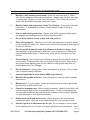
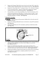
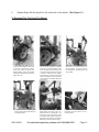
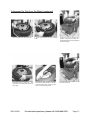
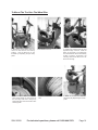
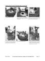
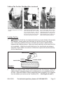
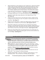
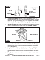
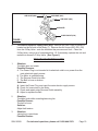
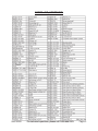
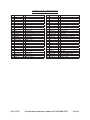
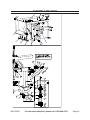
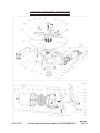
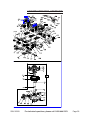
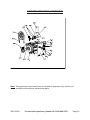
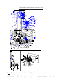
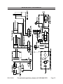
TIRE CHANGE SEMI-AUTOMATIC WITH SWINGING ARM Model 90589 ASSEMBLY and Operating Instructions Visit our website at: http://www.harborfreight.com Read this material before using this product. Failure to do so can result in serious injury. Save this manual. Copyright© 2003 by Harbor Freight Tools®. All rights reserved. No portion of this manual or any artwork contained herein may be reproduced in any shape or form without the express written consent of Harbor Freight Tools. Diagrams within this manual may not be drawn proportionally. Due to continuing improvements, actual product may differ slightly from the product described herein. Tools required for assembly and service may not be included. For technical questions or replacement parts, please call 1-800-444-3353. Revised Manual 10g PRODUCT SPECIFICATIONS Electrical Requirements 220 V / 60 Hz / 10 A Motor 1 HP / 1740 RPM Maximum Tire Diameter 39” Maximum Tire Width 13” External Locking Rim Dimensions 10”-18” Internal Locking Rim Dimensions 12”-20” Maximum PSI Working Pressure 110 PSI Bead Break Force 5,500 lb. Maximum Rotation Torque (Turntable) 795 ft-lb Air Inlet Fitting Size 1/4”-18 NPT Weight 566 lb SAVE THIS MANUAL You will need this manual for the safety warnings and precautions, assembly, operating, inspection, maintenance and cleaning procedures, parts list and assembly diagram. Keep your invoice with this manual. Write the invoice number on the inside of the front cover. Keep this manual and invoice in a safe and dry place for future reference. GENERAL SAFETY RULES WARNING! Read all instructions Failure to follow all instructions listed below may result in electric shock, fire, and/or serious injury. The term “power tool” in all of the warnings listed below refers to your mains-operated (corded) power tool or battery-operated (cordless) power tool. SAVE THESE INSTRUCTIONS WORK AREA 1. Keep your work area clean and well lit. Cluttered benches and dark areas invite accidents. 2. Do not operate power tools in explosive atmospheres, such as in the presence of flammable liquids, gases, or dust. Power tools create sparks which may ignite the dust or fumes. 3. Keep bystanders, children, and visitors away while operating a power tool. Distractions can cause you to lose control. Protect others in the work area from debris such as chips and sparks. Provide barriers or shields as needed. SKU 90589 For technical questions, please call 1-800-444-3353. Page 2 ELECTRICAL SAFETY 1. Grounded tools must be plugged into an outlet properly installed and grounded in accordance with all codes and ordinances. Never remove the grounding prong or modify the plug in any way. Do not use any adapter plugs. Check with a qualified electrician if you are in doubt as to whether the outlet is properly grounded. If the tools should electrically malfunction or break down, grounding provides a low resistance path to carry electricity away from the user. 2. Double insulated tools are equipped with a polarized plug (one blade is wider than the other). This plug will fit in a polarized outlet only one way. If the plug does not fit fully in the outlet, reverse the plug. If it still does not fit, contact a qualified electrician to install a polarized outlet. Do not change the plug in any way. Double insulation eliminates the need for the three wire grounded power cord and grounded power supply system. 3. Avoid body contact with grounded surfaces such as pipes, radiators, ranges, and refrigerators. There is an increased risk of electric shock if your body is grounded. 4. Do not expose power tools to rain or wet conditions. Water entering a power tool will increase the risk of electric shock. 5. Do not abuse the Power Cord. Never use the Power Cord to carry the tools or pull the Plug from an outlet. Keep the Power Cord away from heat, oil, sharp edges, or moving parts. Replace damaged Power Cords immediately. Damaged Power Cords increase the risk of electric shock. PERSONAL SAFETY 1. Stay alert. Watch what you are doing, and use common sense when operating a power tool. Do not use a power tool while tired or under the influence of drugs, alcohol, or medication. A moment of inattention while operating power tools may result in serious personal injury. 2. Dress properly. Do not wear loose clothing or jewelry. Contain long hair. Keep your hair, clothing, and gloves away from moving parts. Loose clothes, jewelry, or long hair can be caught in moving parts. 3. Avoid accidental starting. Be sure the Power Switch is off before plugging in. Plugging in power tools with the Power Switch on, invites accidents. 4. Remove adjusting keys or wrenches before turning the power tool on. A wrench or a key that is left attached to a rotating part of the power tool may result in personal injury. SKU 90589 For technical questions, please call 1-800-444-3353. Page 3 5. Do not overreach. Keep proper footing and balance at all times. Proper footing and balance enables better control of the power tool in unexpected situations. 6. Use safety equipment. Always wear eye protection. Dust mask, non-skid safety shoes, hard hat, or hearing protection must be used for appropriate conditions. TOOL USE AND CARE 1. Do not force the tool. Use the correct tool for your application. The correct tool will do the job better and safer at the rate for which it is designed. 2. Do not use the power tool if the Power Switch does not turn it on or off. Any tool that cannot be controlled with the Power Switch is dangerous and must be replaced. 3. Disconnect the Power Cord Plug from the power source before making any adjustments, changing accessories, or storing the tool. Such preventive safety measures reduce the risk of starting the tool accidentally. 4. Store idle tools out of reach of children and other untrained persons. Tools are dangerous in the hands of untrained users. 5. Maintain tools with care. Keep cutting tools sharp and clean. Properly maintained tools with a sharp cutting edge are less likely to bind and are easier to control. Do not use a damaged tool. Tag damaged tools “Do not use” until repaired. 6. Check for misalignment or binding of moving parts, breakage of parts, and any other condition that may affect the tool’s operation. If damaged, have the tool serviced before using. Many accidents are caused by poorly maintained tools. 7. Use only accessories that are recommended by the manufacturer for your model. Accessories that may be suitable for one tool may become hazardous when used on another tool. SERVICE 1. Tool service must be performed only by qualified repair personnel. Service or maintenance performed by unqualified personnel could result in a risk of injury. 2. When servicing a tool, use only identical replacement parts. Follow instructions in the “Inspection, Maintenance, And Cleaning” section of this manual. Use of unauthorized parts or failure to follow maintenance instructions may create a risk of electric shock or injury. REV 07g SKU 90589 For technical questions, please call 1-800-444-3353. Page 4 SPECIFIC SAFETY RULES 1. Maintain a safe working environment. Keep the work area well lit. Make sure there is adequate surrounding workspace. Always keep the work area free of obstructions, grease, oil, trash, and other debris. Do not use this product in areas near flammable chemicals, dusts, and vapors. 2. Maintain labels and nameplates on the Tire Changer. These carry important information. If unreadable or missing, contact Harbor Freight Tools for a replacement. 3. Use eye and hearing protection. Always wear ANSI approved safety impact eye goggles and hearing protectors when using this product. 4. Do not allow children to use or play with this product. 5. Store idle equipment. When not in use, tools and equipment should be stored in a dry location to inhibit rust. Always lock up tools and equipment, and keep out of reach of children. 6. Do not use this product if under the influence of alcohol or drugs. Read warning labels on prescriptions to determine if your judgement or reflexes are impaired while taking drugs. If there is any doubt, do not attempt to use this product. 7. Dress properly. Do not wear loose clothing or jewelry as they can be caught in moving parts. Wear restrictive hair covering to contain long hair. Wear heavy duty gloves when handling tires, but be careful to keep gloves away from all moving parts of the Tire Changer. 8. Do not overreach. Keep proper footing and balance at all times. Do not reach over or across running machines. 9. Industrial applications must follow OSHA requirements. 10. Maintain this product with care. Keep this product clean for better and safer performance. 11. Maintenance: For your safety, service and maintenance should be performed regularly by a qualified technician. 12. Check for damaged parts. Before using this product, carefully check that it will operate properly and perform its intended function. Check for damaged parts and any other conditions that may affect the operation of this product. Replace or repair damaged or worn parts immediately. 13. Replacement parts and accessories: When servicing, use only identical replacement parts. Only use accessories intended for use with this product. 14. Use the right tool or attachment for the job. Do not attempt to force a small tool or attachment to do the work of a larger industrial tool or attachment. There REV 07g SKU 90589 For technical questions, please call 1-800-444-3353. Page 5 are certain applications for which this product was designed. It will do the job better and more safely at the rate for which it was intended. Do not modify this product, and do not use this product for a purpose for which it was not intended. 15. WARNING: The Tire Changer requires the assembly of a UL, CSA, or CE listed, 220 Volt, 3-Prong Electrical Plug (not provided) onto the unit’s electrical power cord. The National Electric Code requires that the GREEN wire on the unit must be used as the GROUND wire. The “HOT” wires on the power cord are the BLACK and WHITE wires. Do not attempt to alter the 220 Volt, 3-Prong Plug or its assembly to the power cord (as mentioned above) in any way. In addition, it is recommended that this assembly procedure be carried out by a qualified electrician. 16. CAUTION! Prior to performing any services or maintenance on the Tire Changer, always disconnect the Tire Changer from its air supply source. Pump the Bead Breaker Pedal several times to evacuate all compressed air from the machine, and disconnect the unit from its electrical supply source. 17. Use only clean, dry, regulated, compressed air at up to 110 PSI (8-BAR). Never use oxygen, carbon dioxide, combustible gases, or any other bottled gas as a power source for this machine. 18. EXPLOSION DANGER! Never overinflate tires or other inflatable items. When inflating a tire with compressed air, make sure to inflate the tire to the exact PSI as recommended by the tire manufacturer. Always observe Pressure Gauge of Tire Changer to check the actual pressure in tires. 19. To avoid personal injury and/or machine damage, always make sure the tire rim is firmly secured on the Tire Changer with its Jaws. 20. Never place your hands or fingers between the vehicle wheel rim and the Jaws of the Tire Changer during the locking/clamping stage. 21. Dispose of old tires in accordance with local, state, and federal laws. 22. People with pacemakers should consult their physician(s) before use. Electromagnetic fields in close proximity to heart pacemaker could cause pacemaker interference or pacemaker failure. 23. WARNING! The warnings, precautions, and instructions discussed in this manual cannot cover all possible conditions and situations that may occur. The operator must understand that common sense and caution are factors which cannot be built into this product, but must be supplied by the operator. REV 07g, 07k SKU 90589 For technical questions, please call 1-800-444-3353. Page 6 UNPACKING When unpacking, check to make sure all the parts shown on the Parts Lists near the end of this manual are included. If any parts are missing or broken, please call Harbor Freight Tools at the number shown on the cover of this manual as soon as possible. ASSEMBLY INSTRUCTIONS Note: For additional information regarding the parts mentioned in the following pages, refer to the Assembly Diagrams near the end of this manual. 1. With assistance and a proper lifting device, carefully move the Tire Changer to the desired workplace location. Make sure to position the Tire Changer on a flat, level, dry, floor surface capable of bearing the weight of the Tire Changer, operator, additional tools, tires, etc. 2. Using the four mounting holes located at the Tire Changer’s base as a template, mark the spots where four 3/8” diameter mounting holes will be drilled in the floor surface. Then, temporarily set the Tire Changer aside. 3. Drill the four, pre-marked, 3/8” holes in the floor surface (about 4” deep). Then, insert a 3/8” expansion plug (not included) in each of the four holes. 4. Move the Tire Changer back to its original position, making sure to align its four mounting holes with the four pre-drilled holes in the floor surface. Once the holes are aligned and the Tire Changer is level, insert four 3/8” bolts (not included) through the mounting holes and into the expansion plugs. Secure the Tire Changer to the floor surface by tightening the four 3/8” bolts. 5. Prior to assembling and using the Tire Changer, it is recommended that you familiarize yourself with the main components of the unit. (See Figure A.) 6. NOTE: Prior to beginning the assembly procedures, make sure to remove all the additional parts and accessories from the shipping boxes that are included with the Tire Changer. REV 07g SKU 90589 For technical questions, please call 1-800-444-3353. Page 7 Locking Handle Bar (142) Hex Vertical Arm (120) Mounting Head (123) Vertical Column (101) Jaw (203) Turntable (201) Air Tank (IT1) Filter & pressure reducer + lubr. (IT207) Bead Lifting Lever (13) Bead breaker arm (321) Inflation Pedal (IT106) Shovel (315) Tilting Pedal (404) Rubber wheel support (3 & 11) Clamping Pedal (403) Bead Breaker Pedal (402) 7. Figure A Reverse Pedal (401) Vertical column assembly procedure: 1) With assistance, place the Column (1, Fig. B-1) in its seating on the Body Assembly (2, Fig. B-1). Push the Air Hose (3, Fig. B-1) through the large round hole into the body. 2) Insert the Pin (13, Fig. B-1) through the column as shown in Fig. B-1 and fasten it with Screws (14, Fig. B-1) and Washers (15, Fig. B-1). 3) Using the Screw (17, Fig. B-1) tighten with the Self- Locking Nut (16, Fig. B-1) to connect the Pin (18, Fig. B-1) of the post tilting cylinder. 4) Remove the four Screws (4, Fig. B-1) from the left Side Cover (6, Fig. B-1) and remove it. Connect the Air Hose (3, Fig. B-1) from the column to the 6mm Connector (5, Fig. B-1). 5) Replace the Side Cover (6, Fig. B-1) and fasten it with the Screws (4, Fig. B-1). Figure B-1 6) Install the plastic guard and fix it with the two Cap Screws (10, Fig. B-1). 7) Fix the Metal Sheeting Guard (11, Fig. B-1) to the back of the vertical column (1, Fig. B-1) using the two Cap Screws (12, Fig. B-1). SKU 90589 For technical questions, please call 1-800-444-3353. REV 07g Page 8 SCREW (114) KNOB (115) SPRING (117) PLASTIC COVER (116) SELF-LOCKING NUT (137) VERTICAL LOCKING PLATE (118) VERTICAL ARM (120) SCREW (113) SCREW (129) SCREW (129) FIGURE B-2 8. Loosen the three Screws (113 & 129). Then, lift up and remove the Plastic Cover (116). (See Figure B-2.) 9. With assistance, slide the Vertical Arm (120) fully upward and hold. NOTE: You may wish to place wooden blocks under the Vertical Arm in order to keep the Vertical Arm in its upward position throughout this assembly procedure. (See Figure B-2.) 10. Temporarily unscrew and remove the Self-Locking Nut (137) from the Vertical Locking Plate (118). (See Figure B-2.) 11. Insert the Spring (117) onto the upper portion of the Vertical Arm (120), and allow the Spring to rest upon the Vertical Locking Plate (118). (See Figure B-2.) 12. Re-tighten the Self Locking Nut (137) into the Vertical Locking Plate (118) in order to secure the Spring (117) to the Vertical Locking Plate. (See Figure B-2.) 13. Insert the Knob (115) onto the upper portion of the Spring (117). Push the Knob firmly down, while compressing the Spring, until the Knob contacts the upper portion of the Vertical Arm (120). Then secure the Knob to the Vertical Arm, using the Screw (114). (See Figure B-2.) CAUTION! Use extreme caution when compressing the Spring (117). Compressing the Spring will cause resistance which could result in personal injury should the Spring suddenly expand. Maintain a firm grip on the Knob (115) while compressing the Spring. Firmly tighten the Screw (114) to secure the Knob to the Vertical Arm. (See Figure B-2.) REV 07g SKU 90589 For technical questions, please call 1-800-444-3353. Page 9 14. Re-attach the Plastic Cover (116), and re-tighten the three Screws (113 & 129). If using wooden blocks to support the Vertical Arm (120), remove the blocks. (See Figure B-2.) 15. NOTE: For shipping purposes, the Shovel (315) is restrained with a temporary tie-down bracket. Make sure to remove and discard the bracket. (See Figure A.) 16. Lay out the Tool Box (IT42) and Tool Box Support (IT38). (See Assy. Diagram.) 17. Attach the Tool Box Support (IT38) to the Body (1) of the Tire Changer, using the Mounting Bracket Bolts. (See Assy. Diagram.) 18. Attach the Tool Box (IT42) to the Tool Box Support (IT38), using the Mounting Bracket Bolts. (See Assy. Diagram.) 19. Remove the Left Side Cover (8) from the Body (1) to expose the inside of the Tire Changer. (See Assy. Diagram.) 20. Run the Hose (IT15) through the opening in the Body (1) of the Tire Changer. Then, connect the Hose to the 5-Way Valve (IT17). (Note location in Assy. Diagram.) 21. Re-attach the Left Side Cover (8) to the Body (1) of the Tire Changer. (See Assy. Diagram.) 22. Assembly of the Tire Changer should be complete and the machine now ready to operate. Only set up and use the Tire Changer on a flat, level surface that is capable of supporting the weight of this heavy tool (566 lb.) and all required tools and tires. OPERATING INSTRUCTIONS To Perform Preliminary Operating Tests: 1. Plug the Power Cord into the nearest 220 volt, grounded, electrical outlet. 2. Connect the air compressor’s supply hose (not included) to the Filter & Pressure Reducer + Lubr. (IT201 thru IT205). Set the air compressor’s regulator to no more than 110 PSI. Turn on the air compressor, and allow sufficient time for adequate build-up of compressed air. (See Figure A.) 3. Depress the Reverse Pedal (401) down. The Turntable (201) should turn in a clockwise direction. Pull the Reverse Pedal up, and the Turntable should turn counterclockwise. (See Figure A.) 4. Open the Bead Breaker Arm (321) manually, and depress the Bead Breaker Pedal (402). The Bead Breaker Arm will close. When the Bead Breaker Pedal is released, the Pedal should return to its original position. (See Figure A.) REV 07g SKU 90589 For technical questions, please call 1-800-444-3353. Page 10 5. Depress the Clamping Pedal (403) once to open the four Jaws (203). When the Clamping Pedal is depressed again, the four Jaws should close. (See Figure A.) 6. Depress the Tilting Pedal (404). The Vertical Column (101) will tilt back, bringing it to a non-working position. When the Tilting Pedal is released, the Vertical Column will return to its original working position. (See Figure A.) 7. Press the Button on the Locking Handle Bar (142). Both the Vertical Arm (120) and the horizontal Mounting Head Assy. (131) will be locked in position. Press the Button inside the Locking Handle Bar, and the Vertical Arm and Horizontal Mounting Head Assy. is released. (See Figure A.) To Break The Tire Bead: CAUTION! Before carrying out this procedure, deflate the tire fully and remove all of its wheel weights. 1. Depress the Clamping Pedal (403) twice to close the four Jaws (203) completely. (See Figure A.) 2. Open the Bead Breaker Arm (321) manually by pushing it towards the outside. (See Figure A.) SHOVEL (315) FIGURE C 3. Place the wheel up against the Rubber Wheel Support (3 & 11). Bring the Shovel (315) against the bead about four inches from the edge of the wheel rim. (See Figures A and C.) 4. Depress the Bead Breaker Pedal (402) to fully activate the Shovel (315). Release pressure on the Bead Breaker Pedal when the Shovel has reached the end of its travel and/or when the tire bead is broken. (See Figures A and C.) 5. Rotate the tire slightly, and repeat the procedure around the entire circumference of the wheel rim until the bead is completely detached from the wheel rim. (See Figures A and C.) SKU 90589 For technical questions, please call 1-800-444-3353. Page 11 6. Repeat Steps #2 through #6 for the other side of the wheel. (See Figure C.) To Demount The Tire From The Wheel: 1. Deflate the tire fully !!! Open the bead breaker arm by hand by pushing it towards the outside. Place the wheel up against the Rubber Buffer. Bring the Paddle against the bead about 3/8” from the edge of the rim. 4. Depress the column tilting pedal again and the vertical Arm will return to original position. SKU 90589 2. Depress the bead breaker pedal fully to activate the paddle. Release pressure on the bead breaker pedal, when the blade has reached the end of its travel and/or when the tire bead is broken. Rotate the tire slightly, and repeat the procedure around the entire circumference of the wheel rim until the bead is completely detached from the rim. 5. Position the mounting head by hand against the edge of the rim. Press the button on the handle. The vertical Arm and Horizontal Arm will be automatically locked in position; meanwhile, the mounting head will be lifted 1/16”-1/8” above the rim edge. 3. Depress the column tilting pedal; the column is tilted back to nonworking position. Lock the wheel on the turntable by depressing the jaw clamp pedal. 6. Insert the lever between the tire bead and the front section of the mounting head. For technical questions, please call 1-800-444-3353. Page 12 To Demount The Tire From The Wheel: (continued) 7. Then work the lever around the tire. 10. Continue until the tire is completely separated from the wheel rim. And remove the inner tube (if the tire has an inner tube). SKU 90589 8. Move the tire bead over the mounting head. 11. Insert the lever between the other side of the tire bead and the front section of the mounting head. Move the tire bead over the mounting head. 9. With the lever (or hands) held in position, rotate the turntable in a clockwise direction by fully depressing the reverse pedal. 12. Repeat the above steps for the other side of the tire. For technical questions, please call 1-800-444-3353. Page 13 To Mount The Tire Onto The Wheel Rim: 1. Depress the column tilting pedal; the column is tilted back to non-working position. Lock the wheel rim on the turntable by depressing the jaw clamp pedal. 4. Move the tire so that the bead farthest away passes below the front section of the mounting head and is brought up against the edge of the rear section of the mounting head. SKU 90589 2. Put the tire on the rim. 5. Here is how it looks from the other side. 3. Position the mounting head by hand against the edge of the rim. Press the button on the handle. The vertical Arm and Horizontal Arm will be automatically locked in position; meanwhile, the mounting head will be lifted 1/16”-1/8” above the rim edge. 6. Rotate the turntable in a clockwise direction by fully depressing the reverse pedal. For technical questions, please call 1-800-444-3353. Page 14 To Mount The Tire Onto The Wheel Rim: (continued) 7. Continue until the bead farthest away is 8. Insert the inner tube (if there is one). And completely onto the wheel rim. spread tire grease (or a similar lubricant) liberally on the complete circumference of the tire bead. 10. Keep the tire bead pressed down into the wheel rim channel with your hands (or the lever). Then, depress the reverse pedal to rotate the turntable clockwise. SKU 90589 11. Continue this process throughout the entire circumference of the wheel and tire. 9. Move the tire so that the bead passes below the front section of the mounting head and is brought up against the edge of the rear section of the mounting head. 12. If the tire locks up in above step, pull the reverse pedal up to rotate the turntable counterclockwise to unlock it. Check the wheel rim and the tire are of the same size. And try again. For technical questions, please call 1-800-444-3353. Page 15 To Mount The Tire Onto The Wheel Rim: (continued) 13. Depress the column tilting pedal; the column is tilted back to non-working position. 14. Press the inflating pedal down to the middle position to start tire inflation. Inflate the tire with brief jets of air! Checking the air pressure frequently. Once the proper air pressure has been reached, disconnect the nozzle from the valve stem and screw a valve cap onto the stem. 15. For a tubeless tire, if the bead of the tire is not well seated, due to a strong bead, lift tire manually until the upper bead seals against the rim, then press the pedal all the way down. A strong jet of air will be released through the nozzles in the slides and this will help the bead seal. To Inflate The Tire: 1. WARNING! A burst tire can cause serious injury or even death to the operator or bystander. Always make sure the wheel rim and the tire are of the same size. Check the condition of the tire, and make sure it has no defects before beginning the inflation process. Keep your hands and body as far away from the tire as possible. Inflate the tire with briefs jets of air, checking the air pressure frequently. Never inflate a tire above or below the air pressure recommended by the tire manufacturer. TIRE AIR HOSE VALVE STEM NOZZLE LOCKING LEVER FIGURE F 2. There is an Inflation Pedal (IT106) on the left side of the Tire Changer. When the Inflation Pedal is depressed down to its middle position, air is released from the air hose. When the Inflation Pedal is depressed down completely, air is released from the inflation jet nozzles on the Turntable (201). (See Figures A and F.) SKU 90589 For technical questions, please call 1-800-444-3353. Page 16 3. While the wheel/tire is still clamped onto the Turntable (201), depress the Inflation Pedal (IT106) completely while slightly raising and lowering the tire by hand to contact the beads on both sides of the tire with the edges on both sides of the wheel rim. Meanwhile, air is being released from the inflation jet nozzles on the Turntable, expanding the tire until the beads on both sides make complete contact with the full circumference of the wheel rim on both sides and seal the beads to the edges of the wheel rim. (See Figures A and F, previous page.) 4. Immediately when there is an air tight seal between the beads on both sides and wheel rims on both sides release pressure on the Inflation Pedal (IT106). (See Figure A.) 5. Attach the Nozzle of the air hose to the valve stem of the tire. Make sure the Locking Lever of the Nozzle is in the “UP” position to lock the Nozzle onto the valve stem. (See Figure F.) 6. Depress the Air Inflator Button. Depress the Inflation Pedal (IT106) down to its middle position to release air from the air hose. (See Figures A and F.) 7. Remember to inflate the tire with brief jets of air, checking the air pressure frequently. Once the proper air pressure has been reached, release pressure on the Inflation Pedal (IT106). Disconnect the nozzle of the air hose from the valve stem of the tire, and screw a valve cap onto the stem. (See Figures and F.) 8. Depress the Tilting Pedal (404) so the Vertical Column (101) will tilt back to its non-working position, release the clamping jaws and remove the wheel/tire from the Tire Changer. (See Figure A.) INSPECTION AND MAINTENANCE WARNING! Prior to performing any inspection or maintenance procedures, disconnect the Tire Changer from its air supply source. Pump the Bead Breaker Pedal (402) several times to evacuate all compressed air from the machine, and disconnect the unit from its electrical supply source. 1. Before each use: Inspect the general condition of the Tire Changer. Check for misalignment or binding of moving parts, cracked or broken parts, damaged wiring, damaged air hoses, and any other condition that may affect its safe operation. If abnormal noise or vibration occurs, have the problem corrected before further use. Do not use damaged equipment. 2. Daily: Clean the machine daily to remove any dirt or tire debris from the Jaw Slides (202). Then, lubricate the Slides with grease. 3. At least once per week: Clean the Turntable (201) with detergent or a nonflammable solvent. Then, lubricate the Jaw Slides (202) with grease. SKU 90589 For technical questions, please call 1-800-444-3353. Page 17 FIGURE G OIL CAP OIL REGULATOR SCREW FILTER & PRESSURE REDUCER (IT205) RED NOTCH JAR SIGHT GLASS LUBRICATOR (IT204) JAR LOCKING RING 4. At least once per month: Check the oil level in the Lubricator (IT204). If necessary, remove the Oil Cap. Fill the Tank with SAE 30-weight oil, and replace the Oil Cap. Also, make sure that one drop of oil is injected into the Tank every 3-4 times the Bead Breaker Pedal (402) is depressed. If necessary, regulate the rate of oil injection with the Oil Regulator Screw. (See Figure G.) 5. After the first twenty days of use: Re-tighten the Jaws Tightener (218) and the Screws (214) located on the Turntable Slides (201). (See Assy. Diagram.) MOTOR SUPPORT (622) BELT (605) FIGURE H MOTOR (601) SCREW (618) 6. In the event of a loss of power: Check to see if the Belt (605) is tight. To do so, remove the Left Cover (8) which is located on the left side of the Body (1). Regulate the Belt tension by adjusting the Screw located on the Motor Support (622). (See Figure H.) 7. Daily: Check the level of water in the Filter & Pressure Reducer (IT205). The level must never reach above the Red Notch in the Jar’s Sight Glass. When necessary, drain the water by turning the Locking Ring clockwise. (See Figure G.) 8. Every 30-40 days: Dismantle the Jar to remove any solids collected inside it. (See Figure G.) SKU 90589 For technical questions, please call 1-800-444-3353. Page 18 AIR HOSE (428) AIR HOSE (430) AIR HOSE (429) SILENCER 5-WAY VALVE (432) FIGURE I To clean or replace a 5-Way Valve (432): Remove the Left Cover (8) which is located on the left side of the Body (1). Remove the Air Hoses (428, 429, 430) from the 5-Way Valve - note the locations they are removed from. Clean the 5-Way Valve, using a jet of compressed air. Or if necessary, replace the unit and reattach air hoses to 5-Way Valve. (See Figure I.) 9. TROUBLESHOOTING GUIDE 1. Situation: Turntable does not rotate. Possible Reasons: A. The Power Plug is not inserted in its electrical outlet or no power from the main electrical supply source. B. The Motor is malfunctioning C. The Reverse Pedal is broken. D. The Belt is loose or broken. Solutions: A. Insert the Power Plug, and reset the main electric supply source. B. Check for loose wires in the Motor. C. Check and repair entire Reverse Pedal assembly. D. Adjust or replace the Belt. 2. Situation: Turntable locks while mounting/removing tire. Possible Reason: The belt is loose. Solution: Adjust belt tension. 3. Situation: Jaws slow to open/close Possible Reason: SKU 90589 For technical questions, please call 1-800-444-3353. Page 19 The silencer is clogged. Solution: Clean or replace the silencer. 4. Situation: Turntable does not lock the wheel rim correctly. Possible Reasons: A. The jaws are worn. B. Defective piston Solutions: A. Replace jaws B. Replace plate cylinder gasket. 5. Situation: Tool touches the wheel rim during tire mounting/demounting process. Possible Reasons: A. The Locking slide is incorrectly adjusted or defective. B. The Locking slide screw is loose. Solutions: A. Adjust or replace the locking slide. B. Tighten the screw. 6. Situation: Bead Breaker Pedal and Jaw clamp pedal lock out of position. Possible Reason: Return spring of the pedal broken. Solution: Replace spring. 7. Situation: Bead breaking operation difficult Possible Reasons: A. The silencer is clogged. B. The Value shaft O-ring is broken. C. The cylinder piston V-seal or O-ring are broken Solutions: A. Clean or replace the silencer. B. Replace the O-ring. C. Replace the V-seal or O-ring. SKU 90589 For technical questions, please call 1-800-444-3353. Page 20 PLEASE READ THE FOLLOWING CAREFULLY THE MANUFACTURER AND/OR DISTRIBUTOR HAS PROVIDED THE PARTS LIST AND ASSEMBLY DIAGRAM IN THIS MANUAL AS A REFERENCE TOOL ONLY. NEITHER THE MANUFACTURER OR DISTRIBUTOR MAKES ANY REPRESENTATION OR WARRANTY OF ANY KIND TO THE BUYER THAT HE OR SHE IS QUALIFIED TO MAKE ANY REPAIRS TO THE PRODUCT, OR THAT HE OR SHE IS QUALIFIED TO REPLACE ANY PARTS OF THE PRODUCT. IN FACT, THE MANUFACTURER AND/OR DISTRIBUTOR EXPRESSLY STATES THAT ALL REPAIRS AND PARTS REPLACEMENTS SHOULD BE UNDERTAKEN BY CERTIFIED AND LICENSED TECHNICIANS, AND NOT BY THE BUYER. THE BUYER ASSUMES ALL RISK AND LIABILITY ARISING OUT OF HIS OR HER REPAIRS TO THE ORIGINAL PRODUCT OR REPLACEMENT PARTS THERETO, OR ARISING OUT OF HIS OR HER INSTALLATION OF REPLACEMENT PARTS THERETO. SKU 90589 For technical questions, please call 1-800-444-3353. Page 21 PARTS LIST C2110108 1 Rubber wheel support (2) � � � (1) � � � � � � � � � SKU 90589 SKU 90589 � � � � For technical questions, please call 1-800-444-3353. PAGE 22 Page 22 PARTS LIST, CONTINUED C2110019 PL08-01 SKU 90589 For technical questions, please call 1-800-444-3353. REV 08l, 10g Page 23 PARTS LIST, CONTINUED 442 443 444 445 446 447 448 449 450 C233011213 GB/T 41 GB/T 70 C211011213 GB/T 95 GB/T 973 GB/T 1337 GB/T 95 GB/T 70 1 1 1 1 2 3 3 3 1 Pedals shaft Nut M6 Screw M6×40 Twist-spring Washer C 6 Screw M5×40 Self-locking nut M5 Washer C 5 Screw M5×40 452 453 454 455 456 PK8 C2110361 C2110361 PG08-06 NSE08-01 1 1 1 1 2 5-way union Hose (5-way union to locking cylinder) Hose( input to 5-way union) Union Adjust valve C211015203 GB/T 297 GB/T 10708 C211015207 GB/T 41 GB/T 1096 C211015206 GB/T 292 C211015202 C211015201 C211015208 GB/T 70 1 2 1 1 1 1 1 2 1 1 1 10 451 457 501 502 503 504 505 506 507 508 509 510 511 515 489244250019 489244250046 SKU 90589 2 1 Complete 5-way valve Complete 5-way valve Bottom cover Roller bearing 30204 V-seal Gear box pulley Nut M10 Key 6×20 Worm screw Bearing 7010 Worm gear shaft Worm gear Spacer Screw M10×18 516 517 518 519 520 521 522 529 601 602 603 604 605 606 607 608 609 613 614 615 616 617 618 619 620 621 622 623 GB/T95 C211015203 GB/T 1096 GB/T 1096 JB1092 C211015205 GB/T 1337 C2110152 C2110201 GB/T 1096 C2110141 GB/T 712 GB/T 11544 C2110211 C2110212 C2110202 C2110213 IEC947-3 C2110154 GB/T95 GB/T 93 GB/T 70 GB/T 70 GB/T 41 C2110154 C2110154 C2110110 C202011217 10 1 1 1 2 1 10 1 1 1 1 1 1 1 1 1 1 1 2 2 2 2 2 8 2 8 1 1 Washer f 10 Upper cover Key 10×40 Key 14×40 O-ring f 34 Plastic cap Self-locking nut M8 Complete Gearbox Motor MY8024 Key 6 ×20 Motor pulley Screw M6×10 Belt A26” Cable (switch to motor) Cable (switch to capacitor) Capacitor Cable Reverse switch Shock absorber washer Washer C 8 Spring washer Screw M8×20 Screw M8×50 Nut M8 Shock absorber washer Shock absorber washer Motor Support Switch Jacket For technical questions, please call 1-800-444-3353. Page 24 PARTS LIST, CONTINUED No. Code IT1 IT2 IT3 IT4 IT5 IT6 IT7 IT8 IT9 IT10 IT11 IT12 IT13 IT14 I2110301 PQ-L10 I2330341 I2110312 PT08-01 KP-L25 C233030104 I21103011702 I2110313 PC08-01 I211011701 C211011704 PC12-04 I2110314 IT15 IT16 IT17 IT18 IT19 IT20 IT21 IT22 IT23 IT24 IT25 IT26 IT27 IT28 IT29 IT30 IT31 IT32 IT33 IT34 IT35 IT36 IT37 IT38 IT39 IT40 IT41 IT42 I2110315 C211011220 I2110316 I2110317 PC08-01 JSM-3T-Z6 C2110327 GB/T41 GB/T5781 GB/T5781 GB/T41 GB/T41 GB/T 42 PL12-04 I233030303 I233030304 I233030301 I233030305 I233030302 I233030103 I233030105 I233030106 GB/T5781 C2110167 C211016504 I2330340 GB/T5781 C2110165 Qt’y 1 1 1 1 1 1 1 1 4 3 1 4 2 2 1 1 1 1 1 2 1 4 4 2 2 2 2 2 2 1 1 1 1 1 1 2 3 1 1 1 6 1 Description Tank Safety valve Hose (tank to quick exhaust) Hose (input to quick exhaust) T-union 1/8” Complete quick exhaust valve Tie-in Rotating valve casing Hose (Rotating union to slide) Union 1/8” Rotating union mandrel O-ring C65x2.65 Connector 1/2” Hose (exhaust to Rotating union) Hose (5-way to IT) Hose (5-way to air input) 5-way valve Hose (5-way to quick exhaust) L-union 1/8” T-union Solenoid hose Nut M6 Screw M6 Screw M10 Nut M10 Spring washer Washer Angle connector 1/2” Tie-in T-Union Quick exhaust valve support Union Union Union L-Union Nip Screw M8 Tools box support T Union Air manometer Screw M5 Tool box No. IT43 IT44 IT45 IT46 IT47 IT48 Code MOV-03A PL08-01 489244292005 PC10-02 GB/T5781 IT49 IT50 IT51 IT52 IT53 IT60 IT101 IT102 IT103 IT104 IT105 IT106 IT107 IT108 IT109 IT110 IT111 IT112 IT113 IT114 IT115 IT116 IT117 IT118 IT119 CIP IT201 IT202 IT203 IT204 IT205 IT206 Qt’y 1 1 1 8 3 2 2 IT2110117 C211033002 489244292202 I2110164 I2110101 GB/T 1239.6 GB/T 50 GB/T 5780 I2110102 I2110103 I2110104 GB/T 5780 GB/T 50 GB/T 1337 GB/T 70 GB/T 1337 GB/T 50 GB/T 70 GB/T 68 GB/T5781 GB/T 1239.6 GB/T 5780 GB/T41 489244290030 JSM-3T-8 C2110351 JSM-L-Z6 C2110331 C2110332 C2110333 IT207 200-03-03 1 1 1 1 1 1 1 1 1 1 1 1 1 1 1 1 1 1 1 1 4 1 1 1 1 1 1 1 1 1 1 1 Description Exhaust valve L-Union 1/8” Connecting block Connector 1/4” Screw for fixing air manometer Hose (rotating union to rear flange of clamping cylinder) Hose (rotating union to front flange of clamping cylinder) Complete rotating union Air outlet hose for IT version Hose Front cover Complete IT box Inflation pedal support Spring Washer 8 Bolt M8×30 Pedal lever Inflation pedal Connecting rod Bolt M4×20 Washer 4 Self-locking nut M4 Screw M6×20 Self-locking nut M6 Washer 6 Screw M8×25 Screw M8×25 Screw M10X70 Spring Bolt M4×20 Nut M10 Complete inflation pedal T-union 1/4” Union 1/4” L-union 1/4” Lubricator Filter and pressure reducer Pressure gauge Filter and pressure reducer + lubr. REV 07g SKU 90589 For technical questions, please call 1-800-444-3353. Page 25 0589 ASSEMBLY DIAGRAM ASSEMBLY DRAWING 3 103,104,105,106,178. SKU 90589 For PAGE technical 27 questions, please call 1-800-444-3353. Page 26 Assembly Drawing, CONTINUED REV 08l SKU 90589 For technical questions, please call 1-800-444-3353. Page 27 89 ASSEMBLY DIAGRAM, CONTINUED Assembly Drawing, CONTINUED 6 SKU 90589 For technical questions, please call 1-800-444-3353. PAGE 29 Page 28 ASSEMBLY DIAGRAM, CONTINUED Assembly Drawing, CONTINUED Note: Some parts are listed and shown for illustration purposes only, and are not E: Some parts are listed and individually shown for illustration purposes available as replacement parts.only, and are not avail- individually as replacement parts. 0589 PAGE 30 SKU 90589 For technical questions, please call 1-800-444-3353. Page 29 ASSEMBLY DIAGRAM, CONTINUED Assembly Drawing, CONTINUED Some partsfor are listed and shown forand illustration purposes only and are not TE: Some partsNote: are listed and shown illustration purposes only, are not available available vidually as replacement parts. 89 SKU 90589 individually as replacement parts. For technical questions, please call 1-800-444-3353. PAGE 31 REV 07g Page 30 PAGE 32 For technical questions, please call 1-800-444-3353. L2 Fuse: 16A/220V SKU 90589 SKU 90589 Electrical Schematic REV 07k Page 31 PNEUMATIC SCHEMATIC Pneumatic Schematic SKU 90589 SKU 90589 For technical questions, please call 1-800-444-3353. PAGE 33 Page 32 Limited 1 year / 90 Day warranty Harbor Freight Tools Co. makes every effort to assure that its products meet high quality and durability standards, and warrants to the original purchaser that for a period of ninety days from date of purchase that the engine/motor, the belts (if so equipped), and the blades (if so equipped) are free of defects in materials and workmanship. Harbor Freight Tools also warrants to the original purchaser, for a period of one year from date of purchase, that all other parts and components of the product are free from defects in materials and workmanship (90 days if used by a professional contractor or if used as rental equipment). This warranty does not apply to damage due directly or indirectly, to misuse, abuse, negligence or accidents, repairs or alterations outside our facilities, normal wear and tear, or to lack of maintenance. We shall in no event be liable for death, injuries to persons or property, or for incidental, contingent, special or consequential damages arising from the use of our product. Some states do not allow the exclusion or limitation of incidental or consequential damages, so the above limitation of exclusion may not apply to you. This warranty is expressly in lieu of all other warranties, express or implied, including the warranties of merchantability and fitness. To take advantage of this warranty, the product or part must be returned to us with transportation charges prepaid. Proof of purchase date and an explanation of the complaint must accompany the merchandise. If our inspection verifies the defect, we will either repair or replace the product at our election or we may elect to refund the purchase price if we cannot readily and quickly provide you with a replacement. We will return repaired products at our expense, but if we determine there is no defect, or that the defect resulted from causes not within the scope of our warranty, then you must bear the cost of returning the product. This warranty gives you specific legal rights and you may also have other rights which vary from state to state. 3491 Mission Oaks Blvd. • PO Box 6009 • Camarillo, CA 93011 • (800) 444-3353 REV 10g SKU 90589 For technical questions, please call 1-800-444-3353. Page 33


![catalogue_pdf [1.82] Mo - Enseirb](http://vs1.manualzilla.com/store/data/006360324_1-6d38883db81245c16ae9c413a1d8cfa1-150x150.png)