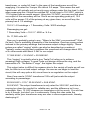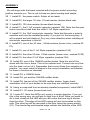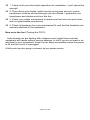
1
Ramsey Electronics Model No. PG13 Have you ever wanted to play with a controlled substance? Now you can! It is called plasma, and it is easily generated by this nifty high voltage kit. This is the same though more powerful supply that is used in Plasma Balls and neon art, and can be used for all sorts of high voltage experiments! Turn a standard light bulb into a plasma sphere! • • • Perfect for driving a Jacob’s ladder. See plasma at work! • Optional 12VAC transformer and this kit are all you need to begin experimenting! • • Can generate sparks up to 2 inches. • Can produce many of the same effects as Tesla Coil, on a smaller scale. • Great for science fairs! Can light many feet of neon tubing Perfect for driving plasma balls, even make a standard light bulb into a plasma sphere! Very thorough manual on high voltage safety, many neat experiments, and lessons learned along the way. DANGER HIGH VOLTAGE See instruction manual before operation PG13 • 1 RAMSEY TRANSMITTER KITS • FM100B Professional FM Stereo Transmitter • FM25B Synthesized Stereo Transmitter • AM1, AM25 AM Transmitters • TV6 Television Transmitter RAMSEY RECEIVER KITS • FR1 FM Broadcast Receiver • AR1 Aircraft Band Receiver • SR2 Shortwave Receiver • AA7 Active Antenna • SC1 Shortwave Converter RAMSEY HOBBY KITS • SG7 Personal Speed Radar • SS70A Speech Scrambler • SP1 Speakerphone • WCT20 Wizard Cable Tracer • ECG1 Heart Monitor • LABC1 Lead Acid Battery Charger • IG7 Ion Generator • CT255 Compu Temp Digital Binary Thermometer • LC1 Inductance-Capacitance Meter RAMSEY AMATEUR RADIO KITS • HR Series HF All Mode Receivers • QRP Series HF CW Transmitters • CW7 CW Keyer • CPO3 Code Practice Oscillator • QRP Power Amplifiers RAMSEY MINI-KITS Many other kits are available for hobby, school, Scouts and just plain FUN. New kits are always under development. Write or call for our free Ramsey catalog. PG13 PLASMA GENERATOR KIT MANUAL Ramsey Electronics publication No. MPG13 Revision 1.1d First printing: November 2001 MRW COPYRIGHT 2001 by Ramsey Electronics, Inc. 590 Fishers Station Drive, Victor, New York 14564. All rights reserved. No portion of this publication may be copied or duplicated without the written permission of Ramsey Electronics, Inc. Printed in the United States of America. PG13 • 2 Ramsey Publication No. MPG13 Price $10.00 KIT ASSEMBLY AND INSTRUCTION MANUAL FOR PG13 PLASMA GENERATOR KIT TABLE OF CONTENTS Safety Guidelines .................................4 History ...................................................9 Circuit Operation .................................12 Learn As You Build .............................16 Parts List .............................................18 Assembly .............................................19 Schematic............................................24 Power Supply ......................................25 Testing.................................................28 Troubleshooting ..................................31 Experiments ........................................32 Component Placement ........................42 Warranty ..............................................43 RAMSEY ELECTRONICS, INC. 590 Fishers Station Drive Victor, New York 14564 Phone (585) 924-4560 Fax (585) 924-4555 PG13 • 3 SAFETY GUIDELINES FOR HIGH VOLTAGE AND/OR LINE POWERED EQUIPMENT Author: Samuel M. Goldwasser Corrections/suggestions: [email protected] Copyright (c) 1994, 1995, 1996, 1997, 1998 All Rights Reserved Reproduction of this document in whole or in part is permitted if both of the following conditions are satisfied: 1. This notice is included in its entirety at the beginning. 2. There is no charge except to cover the costs of copying. Introduction Consumer electronics equipment like TVs, computer monitors, microwave ovens, and electronic flash units, use voltages at power levels that are potentially lethal. Normally, these are safely enclosed to prevent accidental contact. However, during servicing, the cabinet will likely be open and safety interlocks may be defeated. Depending on overall conditions and your general state of health, there is a wide variation of voltage, current, and total energy levels that can kill. Microwave ovens in particular are probably THE most dangerous household appliance to service. There is high voltage - up to 5,000 V or more - at high current - more than an amp may be available momentarily. This is an instantly lethal combination. TVs and monitors may have up to 35 KV on the CRT but the current is low—a couple of milliamps. However, the CRT capacitance can hold a painful charge for a long time. In addition, portions of the circuitry of TVs and monitors - as well as all other devices that plug into the wall socket - are line connected. This is actually more dangerous than the high voltage due to the greater current available - and a few hundred volts can make you just as dead as 35 KV! Electronic flash units and strobelights have large energy storage capacitors which alone can deliver a lethal charge - long after the power has been removed. This applies to some extent even to those little disposable pocket cameras with flash! Even some portions of apparently harmless devices like VCRs and CD players or vacuum cleaners and toasters - can be hazardous (though the live parts may be insulated or protected - but don't count on it! This information also applies when working on other high voltage or line PG13 • 4 connected devices like Tesla Coils, Jacobs Ladders, plasma spheres, gigawatt lasers, fusion generators, and other popular hobby type projects. In addition read the relevant sections of the document for your particular equipment. Specific safety considerations have been included where appropriate. Safety guidelines These guidelines are to protect you from potentially deadly electrical shock hazards as well as the equipment from accidental damage. Note that the danger to you is not only in your body providing a conducting path, particularly through your heart. Any involuntary muscle contractions caused by a shock, while perhaps harmless in themselves, may cause collateral damage - there are many sharp edges inside this type of equipment as well as other electrically live parts you may contact accidentally. The purpose of this set of guidelines is not to frighten you but rather to make you aware of the appropriate precautions. Repair of TVs, monitors, microwave ovens, and other consumer and industrial equipment can be both rewarding and economical. Just be sure that it is also safe! • • • • • • • • • Don't work alone - in the event of an emergency another person's presence may be essential. Always keep one hand in your pocket when anywhere around a powered line-connected or high voltage system. Wear rubber bottom shoes or sneakers. Wear eye protection - large plastic lens eyeglasses or safety goggles. Don't wear any jewelry or other articles that could accidentally contact circuitry and conduct current, or get caught in moving parts. Set up your work area away from possible grounds that you may accidentally contact. Know your equipment: TVs and monitors may use parts of the metal chassis as ground return yet the chassis may be electrically live with respect to the earth ground of the AC line. Microwave ovens use the chassis as ground return for the high voltage. In addition, do not assume that the chassis is a suitable ground for your test equipment! If circuit boards need to be removed from their mountings, put insulating material between the boards and anything they may short to. Hold them in place with string or electrical tape. Prop them up with insulation sticks plastic or wood. If you need to probe, solder, or otherwise touch circuits with power off, discharge (across) large power supply filter capacitors with a 2 W or PG13 • 5 • • • • • • • greater resistor of 100-500 ohms/V approximate value (e.g., for a 200 V capacitor, use a 20K-100K ohm resistor). Monitor while discharging and/ or verify that there is no residual charge with a suitable voltmeter. In a TV or monitor, if you are removing the high voltage connection to the CRT (to replace the flyback transformer for example) first discharge the CRT contact (under the insulating cup at the end of the fat red wire). Use a 1M-10M ohm 1W or greater wattage resistor on the end of an insulating stick or the probe of a high voltage meter. Discharge to the metal frame which is connected to the outside of the CRT. For TVs and monitors in particular, there is the additional danger of CRT implosion - take care not to bang the CRT envelope with your tools. An implosion will scatter shards of glass at high velocity in every direction. There is several tons of force attempting to crush the typical CRT. Always wear eye protection. Connect/disconnect any test leads with the equipment unpowered and unplugged. Use clip leads or solder temporary wires to reach cramped locations or difficult to access locations. If you must probe live, put electrical tape over all but the last 1/16" of the test probes to avoid the possibility of an accidental short which could cause damage to various components. Clip the reference end of the meter or scope to the appropriate ground return so that you need to only probe with one hand. Perform as many tests as possible with power off and the equipment unplugged. For example, the semiconductors in the power supply section of a TV or monitor can be tested for short circuits with an ohmmeter. Use an isolation transformer if there is any chance of contacting line connected circuits. A Variac(tm) (variable autotransformer) is not an isolation transformer! However, the combination of a Variac and isolation transformer maintains the safety benefits and is a very versatile device. See the document "Repair Briefs, An Introduction", available at this site, for more details. The use of a GFCI (Ground Fault Circuit Interrupter) protected outlet is a good idea but will not protect you from shock from many points in a line connected TV or monitor, or the high voltage side of a microwave oven, for example. (Note however, that, a GFCI may nuisance trip at power-on or at other random times due to leakage paths (like your scope probe ground) or the highly capacitive or inductive input characteristics of line powered equipment.) A fuse or circuit breaker is too slow and insensitive to provide any protection for you or in many cases, your equipment. However, these devices may save your scope probe ground wire should you accidentally connect it to a live chassis. When handling static sensitive components, an anti-static wrist strap is recommended. However, it should be constructed of high resistance PG13 • 6 • • materials with a high resistance path between you and the chassis (greater than 100K ohms). Never use metallic conductors as you would then become an excellent path to ground for line current or risk amputating your hand at the wrist when you accidentally contacted that 1000 A welder supply! Don't attempt repair work when you are tired. Not only will you be more careless, but your primary diagnostic tool - deductive reasoning - will not be operating at full capacity. Finally, never assume anything without checking it out for yourself! Don't take shortcuts! Safety tests for leakage current on repaired equipment It is always essential to test AFTER any repairs to assure that no accessible parts of the equipment have inadvertently been shorted to a Hot wire or live point in the power supply. In addition to incorrect rewiring, this could result from a faulty part, solder splash, or kinked wire insulation. There are two sets of tests: DC leakage: Use a multimeter on the highest ohms range to measure the resistance between the Hot/Neutral prongs of the wall plug (shorted together and with the power switch on where one exists) to ALL exposed metal parts of the equipment including metallic trim, knobs, connector shells and shields, VHF and UHF antenna connections, etc. This resistance must not be less than 1M ohm. AC leakage: Connect a 1.5K ohm, 10 Watt resistor in parallel with a 0.15 uF, 150 V capacitor. With your multimeter set on ACV across this combination and the equipment powered up, touch between a known earth ground and each exposed metal part of the equipment as above. WARNING: Take care not to touch anything until you have confirmed that the leakage is acceptable - you could have a shocking experience! The potential measured for any exposed metal surface must not exceed 0.75 V. If the equipment fails either of these tests, the fault MUST be found and corrected before putting it back in service (even if you are doing this for your in-laws!). Some notes regarding the above safety information While the PG13 falls under the high voltage category, many of the safety recommendations do not apply due to the nature of high frequency high PG13 • 7 voltage. This is only true if you do not modify the kit in any way. Here is the reason why, which is very interesting: So here is the abridged answer to your question: Sodium channels are responsible for the initiation and propagation of action potentials. Action potentials are those electrical signals that carry messages throughout the body whether they be neuronal or cardiac in nature. Sodium channels go through a basic gating scheme. Upon membrane depolarization, sodium channels open, or activate, then quickly inactivate or close. Upon repolarization, sodium channels will go back to the resting state at which time they are capable of opening again. Channels require a certain amount of time to recover from inactivation or return to this available resting state. This recovery from inactivation requires on the order of 15 ms. The frequency at which action potentials fire is governed by this recovery. So action potentials can fire about 60 times per second. Stimulation at higher frequencies would for all intents and purposes drive those sodium channels near the point of the stimulation into a long lived inactivated state from which no action potentials could fire. So thus the reason why lower frequency stimulation would be more deleterious than a 2 kHz frequency. Larry E. Wagner II Technical Associate II Dept. of Anesthesiology P.O. Box 604 University of Rochester Medical Center Simply put, your nerves are not fast enough to respond! Does this mean you are not getting electrocuted? No, but current flow is harmless at these frequencies. The real danger comes from RF burns, and that is what you will become aware of the most when you touch the wrong things. Burning flesh smells awful by the way. When you feel a “tickle” from the PG13 it is either from a lower frequency component like 60 Hz, or the “tickle” of a nice RF burn. Yes, they HURT! PG13 • 8 HOW I ARRIVED AT THE PG13. (A little history, if you please!) Let me introduce myself. I am an engineer at Ramsey Electronics, and have been so for over 12 years now. Who said anything about company faithfulness being dead? Anyhow since I was in high school I have been messing around with high voltage, because it is a challenge, a bit risky, and is simply fascinating. I suppose the fixation on high voltage stems from an earlier fascination with fire, but I won’t get into that. The connection is that fire and a good spark are both made of the same stuff: Plasma. This kit is NOT a Tesla Coil by any means, in fact it exhibits very little of the effects that Tesla Coils use to achieve a very high output voltage. Tesla coils use a completely different effect from turns ratios to achieve a high voltage output, which involves transmission line theory, magnetic fields, and a lot of power. Tesla coil’s output voltages are dependant upon factors such at secondary Q factors, and not as much on turns ratios. My PG13 is completely dependant upon turns ratios because the Q factor is too low to exhibit Tesla effects. This project was conceived due to an inability to find those old flyback transformers that do not contain diodes. Diodes convert the output of a television flyback transformer to DC, preventing them from working for many AC experiments. I searched long and hard, and finally found a manufacturer of a perfect experimenter’s coil. No more stopping at the side of the road at an old console TV to see if the flyback is usable! So, what the heck is plasma, you may ask? No, it’s not the plasma in your blood, swimming along with the red blood cells. Plasma is matter in an extremely excited state. Basically it is molecules being repeatedly stripped of their electrons, and then electrons falling back into place. The process of electrons falling into place is what gives sparks and fire (plasma) its characteristic colors. These colors are dependant upon the mixture of gases that the plasma is made up of, and how excited the gases are. Our atmosphere is mostly Nitrogen, with Oxygen and other gases thrown in as an afterthought. Nitrogen emits blues and violets mostly in a low excitement state, and that is why sparks appear violet at low currents, and blue as the current increases. Why is fire orange and yellow? Because particles such as carbon and ash in the plasma are heated to incandescence, like the filament of a light bulb. If not for the particles the flames would be blue, like Natural Gas burning. Aurora Borealis is another example of plasma In this case upper atmosphere molecules are excited by high energy particles from the sun. Auroras vary from green to red, depending on intensity and elevation in the atmosphere. At higher elevations and low atmospheric pressures found in the upper atmosphere, Nitrogen will emit quite a bit of green. Down a few dozen kilometers closer to earth, Oxygen ionizes (turns to plasma) much more easily and Oxygen tends to emit red. That is why you see different colors in aurora. PG13 • 9 To see an aurora closely, we can use Plasma balls. Plasma balls operate by applying a high AC voltage to an electrode in the center of a glass sphere. This high voltage must be high frequency AC in order for any current to get through the glass of the globe and surrounding air by capacitive coupling to your hand or the air. The current actually doesn’t go through the glass, but is induced on either side. Typical voltages are around a few thousand volts for most commercial plasma globes, sometimes around 10,000 volts for some homebrew ones. Typical frequencies are from a few kilohertz to a few tens of kilohertz. Plasma balls will usually employ unusual gases such as helium, neon, xenon, krypton, and argon to achieve different colors and spark types. Since gases usually ionize more easily at low air pressures, a plasma ball’s air is first sucked out with a vacuum pump, and then replaced with a mixture of the above gases at about 1/10 to 1/20 of an atmosphere. These gases are noble gases, also meaning inert, which means that they don’t readily react with other molecules and create dangerous results. There have been reports of Plasma balls working at atmospheric pressure, and we may try that experiment here. I used a small water-controlled vacuum pump at home when I was a kid and a large, green wine bottle. The best I ever got was 4” streamers at the very bottom, which were white due to the quantity of water vapor coming back through my hose. When your budget is $20 a month, you simply can’t afford a vacuum pump. Now that I have a job, I can get all of those toys I always wanted as a kid (if my wife lets me!), but now I needed to make a new supply. My old one looked like a rat’s nest of wires, and the television flyback wouldn’t fit in any plastic case that I could find. It was time to make a new one that looked nice, and didn’t periodically shock me. I decided to use my resources here at work to make a new kit as well as a new toy for me. (The wife won’t stop me if the boss is paying!) Happy experimenting, and I hope you enjoy playing with high voltage as much as I do! Oh, here is a little reference I pulled from the Internet on gases and the colors they make. Pretty neat! Colors and Effects of Various Gases (by Don Klipstein) Helium - In spectrum tubes it glows a brilliant whitish yellow-orange color, somewhat like that of a high pressure sodium lamp. I have heard that this sometimes varies with pressure, current, and container dimensions. Neon - Usually produces dim red blurry streamers with brighter orange "pads" at the ends. If neon is mixed with another gas (other than helium), the streamer color and character is often dominated by the other gas, but the ends of the streamer are orange or pink "pads". PG13 • 10 Carbon Dioxide - Glows a whitish or blue-white color. It is probably good to have no direct contact with metal electrodes for long life with gases that are not completely inert. Carbon dioxide probably requires more voltage than the noble gases. Generally, gases and vapors with monoatomic molecules work with less voltage than others. Nitrogen - Streamers are usually a whitish or grayish pink or light orange. The color may be more gray or lavender at very low currents. The apparent color varies with what kind of lighting it is in contrast with. Requires somewhat higher voltage than noble gases. Air, Oxygen, Water Vapor - These require more voltage than the noble gases and do not glow brightly. I do not recommend these. If you must use any of these, you may also want no direct contact of gas or vapor to metal in order to avoid corrosion problems. Argon - Streamers are violet-lavender. The ends are blue-violet-lavender. Argon and neon. A mixture of around 99.5 percent neon, .5 percent argon has the lowest voltage requirement, but may not look as good as other gases. Argon-Nitrogen mixture (as found in many light bulbs) - Streamers are whitish or grayish pink or orange, but more lavender at low currents. The ends are blue-violet-lavender. Requires a bit more voltage than pure argon. Krypton - Generally lightning-like and close to white or light gray, sometimes purplish or pinkish, depending on background lighting. Sometimes fuzzier and/ or gray-greenish, especially if the pressure and/or peak current are low. Xenon - Usually lightning-like and bluish white or bluish gray. May get fuzzier and more gray or lavenderish gray at lower pressure and lower peak current. Peak currents over a few milliamps favor a more lightning-like appearance even if the RMS current is less than a milliamp. Don Klipstein's web site with plenty of great information on HV and plasma: http://www.misty.com/people/don/index.html PG13 • 11 CIRCUIT OPERATION What is going on with this board may look simple at first, but it is actually quite a difficult design to get working properly and reliably. A lot has to be considered with magnetics when dealing with high voltage, high frequency transformers. Unlike power transformers like the one powering the entire kit, high voltage transformers have a “sweet spot”, or a resonant frequency where they operate the most efficiently. The goal of the design is to get it working above human hearing, otherwise the screech of high frequency from a plasma discharge is deafening. When choosing the transformer for this design, I wanted the best of everything: High Voltage output, High Current, High Resonant Frequency, and the ability to generate this from a relatively low voltage. The transformer company we found delivered four different transformers to us to experiment with, and a bunch of plastic spacers of varying widths. The four transformers had increasing numbers of secondary windings, but all other factors similar. The problem is that the more windings there are on the secondary, the more inductance there is, meaning the resonant frequency would be lower. The largest transformer which had 6500 turns in the secondary would have been perfect to get 12 volts up to 25kV using a low number of turns on the primary, but the resonance was around 13kHz. The sound this emits is intolerable for any length of time. The coil also had the problem of having very thin wire resulting in a low current output. They have to use fine wire to make it fit in the transformer’s plastic case. The smallest coil had 2000 turns on the secondary, which isn’t quite enough to get 25kV from 12V, even in a push-pull configuration. The problem here is we really need more than one turn of wire on the primary to make an effective output. An advantage would be that the transformer oscillated around 35kHz, well above hearing, but almost too high for some effects we would like to make. The transformer we wound up using was the third size, which has 4000 windings on the secondary, which gives us plenty of high voltage output. It also has the larger sized wire, and with the proper spacers would oscillate right around 18kHz. This frequency is above most people’s hearing, but your dog won’t like this too much. So what do those spacers do? Without getting into magnetics too much, they lower the saturation point of the ferric core. This means the core saturates faster with a larger gap, which also translates to a higher operating frequency. This also means, however, that since the core saturates faster, less energy will be transferred from the primary to the secondary, which reduces power output. PG13 • 12 We have included two 0.25mm spacers for you to do experiments with. Since the transformer is specific about its “sweet spot”, we couldn’t run the drive circuit directly from a pulse width modulator circuit (PWM). We may have been able to tune it up really close while there was no load applied, but as soon as we would draw a spark, the frequency would change, and our output would drop considerably. For example if the “sweet spot” was 20kHz, and we were driving the circuit with 20kHz, we may have 20kV on the output. Then, if we add a new load on the output that changes the “sweet spot” to 19kHz, but we are still driving it with 20kHz, the output may drop to only a few kilovolts. Because of this we decided to make the transformer self-resonating. This means as the load changes, so will the frequency, so that the transformer is always running in the sweet spot. The way this oscillator works is by alternately saturating the core, first in one direction, then the other. R1 and R5 are used as a “kick start” for the oscillator. These resistors provide some current to turn the transistors on. Because no two transistors are perfectly alike, one will turn on before the other, providing an imbalance. In Figure 1, The transistor that is turned on stays on, forcing the other transistor to turn off by directing current through the feedback winding of the transformer in the direction required to turn the other transistor off, and turn itself on even harder. For this illustration we’ll say that Q3 is turned on while Q4 is turned off. As this is occurring, magnetic flux in the core is building along with the current being drawn through Q3, because of the side of the winding Q3 is attached to. This current is drawn through the center tap of the primary winding through the winding, and finally down through Q3 to ground. This rising magnetic flux in turn is inducing voltage and current in the high voltage secondary, as well as the feedback winding. This current in the feedback winding pushes the transistor on even harder up to the point that the core of the transformer saturates. Fig 1. Fig 2. Direction of Flux Direction of Flux +V High Voltage +12V -V High Voltage +12V -V High Voltage PG13 • 13 +V High Voltage Once saturation occurs, the flux stops increasing in the core, and the current that was induced in the feedback winding abruptly halts and reverses direction due to a “ringing” effect. This reversal in current direction then turns off Q3 and begins to turn on Q4, which quickly ramps up the flux in the core now heading in the other direction. (Fig 2). This cycle goes back and forth continuously until power is removed. To control the output voltage we can simply adjust our driving voltage. Here’s why I chose a 12.6VAC transformer instead of a 16VAC transformer to be used with your PG13. One quirk we have come across is that our high voltage design cannot produce a high current arc directly to ground. For this to actually occur we would need a lot more parts in the circuit, and also it would reduce the safety considerably. We decided to go for safety and stick with a lower power design. Besides, you can pull some pretty hot arcs onto a screwdriver and other objects, no ground needed! To find out what we have for output voltage is a simple matter of turns ratios. See the chart below to see the transformer secondary windings that were in the different models of transformers that I sampled. Winding Turns Wire Diam. CHT-0126A: 2000 0.1mm CHT-0126B: 2500 0.1mm CHT-0126C: 4000 0.1mm CHT-0126D: 6500 0.06mm Since we chose the C version of the transformer, we see that we have 4000 windings in the secondary. Now we need to know what is in the primary. Since we were trying to achieve highest possible voltage output along with a decent current output, I compromised at 9 turns center tapped on the primary. Since we are in a push-pull configuration, this essentially doubles our supply voltage across the primary. So let’s say we have a 12.6 VAC transformer supplying our kit, and we need to know what our output voltage will be. First we have to find what the supply voltage will become after converting the 12.6VAC which is an RMS value to the DC value after rectification. First we convert to peak to peak: 12.6VAC * SQRT(2) = 17.81 Vpk/pk Then we subtract 1.4 volts for the diode drops in the bridge rectifier. 17.81—1.4 = 16.41 VDC Now realize that the 12.6VAC rating is at the current rating of the PG13 • 14 transformer, or under full load. In the case of the transformer we will be supplying, it is rated for 3 amps. We idle at 0.5 amps. This means the wall transformer will actually put out much more voltage under this low load. In fact after measuring this I found the rectified DC to be close to 19.2 VDC, which is 17% higher than we would expect. Using this 19.2VDC, we can now find what our output of the secondary will be. Since we are operating push-pull, 19.2 volts will be across 1/2 of the primary at any given time, so we will say the primary has 4 1/2 windings. 19.2 V / 4.5 windings = ? Secondary Volts / 4000 windings. Rearranging we get: ? Secondary Volts = 19.2 V * 4000 w / 4.5 w Or: 17,066 volts AC. Now you’re probably going to say: “Where’s the 20kV you promised?” Well, it’s here. Due to switching transients of the transistors, there are some pulses induced in the primary windings that increase output voltage slightly. These pulses are called “ringing” which can also be described as overshoot. Typically under varying load conditions the overshoot will change about 20%, or in other words add about 3.5kV to our output. 17.066 KVAC + 3.5 KVAC = 20.56KVAC. This “ringing” is actually what a true Tesla Coil relies on to achieve amazingly high voltages. A good Tesla coil design utillizes the ring, and the harmonics of it. The better it “rings”, the higher the output. This output value is difficult to measure due to the variety of loads we will run into, but this is a no-load output voltage. As soon as we begin to load the circuit, this will vary quite a bit, since there is no regulation on the output. Now if we used a 16VAC transformer? We will just scale the output according to percentage: 20.56 KVAC + 21% * 20.56 KVAC = 24.8 KVAC. 24.8 KVAC. The output transformer is only rated for 25 KVAC, and this is coming too close for comfort for reliable use, and the difference isn’t very noticeable. Also, 15 VAC stresses our transistors a bit too much. You are free to try it though, just don’t run it continuously. Doing this also voids the warranty since your transformer may arc over in some experiments, thereby destroying it! PG13 • 15 RAMSEY “LEARN-AS-YOU-BUILD” ASSEMBLY STRATEGY Be sure to read through all of the steps, and check the boxes as you go to be sure you didn't miss any important steps. Although you may be in a hurry to see results, before you switch on the power check all wiring and capacitors for proper orientation. Also check the board for any possible solder shorts, and/or cold solder joints. All of these mistakes could have detrimental effects on your kit - not to mention your ego! Kit building tips: Use a good soldering technique - let your soldering iron tip gently heat the traces to which you are soldering, heating both wires and pads simultaneously. Apply the solder to the iron and the pad when the pad is hot enough to melt the solder. The finished joint should look like a drop of water on paper, somewhat soaked in. Mount all electrical parts on the top side of the board provided. The top side is clearly marked with the model and revision numbers of the kit; you can’t miss it. This is the side that has few traces on it and has the silkscreen on it. When parts are installed, the part is placed flat to the board, and the leads are bent on the backside of the board to prevent the part from falling out before soldering (1). The part is then soldered securely to the board (2-4), and the remaining lead length is then clipped off (5). Notice how the solder joint looks on close up, clean and smooth with no holes or sharp points (6). PG13 • 16 We sincerely hope you put this kit together in a professional manner. This project will not work as well as you wished if you don’t follow good assembly techniques, and follow all instructions. No matter how clear we may think our manual is, if you have any questions give us a call at the factory instead of going it alone; we will be happy to help you with any problems. As good engineering and kit building practice we want to mount the parts AS LOW AS POSSIBLE to the board. A 1/4” lead length on a resistor not mounted close to the board can act as an inductor or an antenna, causing all sorts of problems in some circuits. Although this is not an RF circuit, it is best to keep the parts close to the board. For each part, our word "Install" always means these steps: 1. Pick the correct part value to start with. 2. Insert it into the correct PC board location, making sure the part is mounted flush to the PC board unless otherwise noted. 3. Orient it correctly, follow the PC board drawing and the written directions for all parts - especially when there's a right way and a wrong way to solder it in. (Diode bands, electrolytic capacitor polarity, transistor shapes, dotted or notched ends of IC's, and so forth.) 4. Solder all connections unless directed otherwise. Use enough heat and solder flow for clean, shiny, completed connections. Save a few of the longer leads clipped off the components after soldering. These will be used to form jumper wires to connect circuit board traces. Keeping this in mind, lets begin by sorting out our components and crosschecking them against the parts list to make sure we have received everything. NOTE TO NEWCOMERS: If you are a first time kit builder you may find this manual easier to understand than you may have expected. Each part in the kit is checked off as you go, while a detailed description of each part is given. If you follow each step in the manual in order, and practice good soldering and kit building skills, the kit is next to fail-safe. If a problem does occur, the manual will lead you through step by step in the troubleshooting guide until you find the problem and are able to correct it. PG13 • 17 RAMSEY PG13 PARTS LIST Semiconductors 4 1N5408 3 AMP Rectifier diodes (D2,3,4,5) 1 RED LED (D1) 2 TIP31C 100V Bipolar NPN Power Transistors (Q1,2) Resistors 1 100 ohm resistor (brown-black-brown) (R5) 1 1K ohm resistor (brown-black-red) (R1) <- Small Size 1 1K ohm 1/2 Watt resistor (brown-black-red) (R2) <- Large Size 2 30 ohm 1 Watt resistors (brown color, marked 30 Ω) (R3,4) Capacitors 1 0.1uF Ceramic capacitor (marked 104) (C1) 2 0.1uF Mylar capacitors (marked 104, larger than ceramic) (C5,6) 1 10uF Electrolytic capacitor (C2) 2 3300 or 4700uF Electrolytic capacitors (C3, C4) Transformer 1 High voltage transformer winding (Marked CHT-0126G) (XFMR1) 2 U cores. 2 0.25mm nylon spacers 1 U core clamp. 1 piece of plastic tubing for U core clamp Miscellaneous 1 Neon bulb indicator (NE1) 1 Push button switch (S1) 1 Switch cap. 1 3-screw power terminal (J1) 2 TO-220 Gold heatsinks (HS1,2) 1 Piece of Teflon tubing 1 1 1/8” diameter plastic insulating post with pre-drilled holes. 4 Large rubber feet. 1 Small rubber foot. 1 6-32 x 1/2 metal screw. 2 4-40 x 1/4 screws. 2 4-40 lock nuts. 1 1/2” metal ball terminal 1 #16 nail, 1 1/4 inch long PG13 • 18 ASSEMBLY We will begin with the board oriented with the power switch mounting position towards you. This is just to keep our parts locating task simple. 1. Install S1, the power switch. Solder all six leads. 2. Install R2, the larger 1K ohm 1/2 watt resistor (brown-black-red). 3. Install R5, 100 ohm resistor (brown-black-brown) . 4. Install C1, the 0.1uF ceramic capacitor (marked 104). Note that this part looks more like a disk than the other 0.1uF Mylar capacitors. 5. Install C2, the 10uF electrolytic capacitor. Note that this part is polarity sensitive and must be installed properly. If you put it in the wrong way, it will overheat and self-destruct. Pay very close attention when installing all electrolytic capacitors in this kit! 6. Install R3, one of the 30 ohm, 1 Watt resistors (brown color, marked 30 Ω). 7. Install C6, one of the 0.1uF Mylar capacitors (marked 104). 8. Install R4, the other 30 ohm 1 Watt resistor (brown color, marked 30 Ω) 9. Install C5, the other 0.1uF Mylar capacitor (marked 104). 10. Install D2, one of the 1N5408 rectifier diodes. Note the end of the diode with the line or band. This is the cathode end. Current can only flow into this lead, not out of it. Remember that current flows from negative to positive. You must install all diodes in the correct orientation as indicated for them to function as intended! 11. Install D3, a 1N5408 diode. 12. Install D4, yet another 1N5408 rectifier diode. 13. Install D5, the last of the 1N5408 rectifier diodes. Again check orientation of all of your diodes to be sure they are installed correctly. 14. Using a scrap lead from an already installed component, install JMP1. 15. Install R1, 1K ohms (brown-black-red). 16. Locate D1. Note that LEDs only work in a single direction. If you put this in the wrong way, you will get no light from it at all! What you need to do is look closely at the LED and you will notice that one leg is shorter than the other. The edge of the LED casing will also be beveled on this side. This short leg will be mounted in the hole facing the power switch (S1). The shorter leg and beveled edge indicate the cathode of the LED. PG13 • 19 17. Install D1, the red LED. 18. Now here comes a really critical install. Install C3, one of the 3300 or 4700uF electrolytic capacitors. PAY CLOSE ATTENTION TO ORIENTATION! Usually the negative side of the capacitor is indicated with a stripe and large negative (-) symbols. This is the side that will mount away from the positive indicator we show on our PC boards. Hook these babies up the wrong way and you are in for a catastrophic failure! 19. Install C4, the other 3300 or 4700uF electrolytic capacitor. Again pay close attention to orientation. These large capacitors help “smooth” out the DC supply to get rid of most of the 60Hz and 120Hz that remains from the rectification process of D2-D5. These also reduce the hum that would be present when you draw arcs from the high voltage. 20. Install HS1 into the holes provided. DO NOT SOLDER YET! 21. Take Q1, (marked TIP31C) and push the three leads into the holes provided for it. Push the part down until the heatsink tab hole of the transistor lines up with the center hole of HS1. 22. Using one of the 4-40 x 1/4” screws and a 4-40 lock nut, secure the tab of Q1 to the heatsink. Tighten the screw securely so that the tab of the transistor is flush to the heatsink. 23. Making sure the heatsink is flush to the board, solder the two tabs of the heatsink. 24. Solder the three leads of Q1. 25. Install HS2 into the holes provided. DO NOT SOLDER YET! 26. Take Q2, (marked TIP31C) and push the three leads into the holes provided for it. Push the part down until the heatsink tab hole of the transistor lines up with the center hole of HS2. 27. Using the other 4-40 x 1/4” screw and a 4-40 lock nut, secure the tab of Q2 to the heatsink. Tighten the screw securely so that the tab of transistor is flush to the heatsink. 28. Making sure the heatsink is flush to the board, solder the two tabs of the heatsink. 29. Solder the three leads of Q2. 30. Install one of the U cores into one side of the transformer. 31. Holding the U core in with a finger, tilt the board up so the U core installed is facing downward. 32. Install one of the 0.25 mm spacers in each side of the core holes. These need to be sitting flat against the installed U core so we can install PG13 • 20 the other half. 33. Install the other half of the U core. 34. Locate the plastic tubing for the U core clamp. Cut the tubing in half and slide a piece over each end of the clamp. Then use the U core clamp over the top center of the transformer. The clamp cannot be installed along the side of the U core pieces. 35. Install XFMR1, the high voltage transformer (marked CHT-0126G). Make sure all of the wires are through the appropriate holes before soldering any of the wires! 36. Install NE1, the neon light indicator. This is one place we are going to break the rules of mounting components flush to the board. Instead we will stand this part up off the board about 1/2 inch so it will be a bit closer to the transformer, and so we can adjust its position. 37. Using the four large rubber feet, peel and stick them to the bottom of the board in all four corners, wherever they fit best. In the corner by the switch, you will have to set it back so that it doesn’t run into pads on the bottom. 38. Take the small rubber foot and install it on the top of the board near the switch. This provides a place for you to grip while switching on the power so your project doesn’t slide around when trying to turn off the power. 39. Using the 6-32 x 1/2” screw, thread it through from the bottom of the board to the top. You’ll see that this hole is intended to be a tight fit to make it easy to add and remove the plastic post. 40. Carefully thread the bottom of your plastic post down onto the 6-32 x 1/2” screw. Do NOT over-tighten, as it is easy to strip the threads in the plastic. The next part is a little tricky but we’re sure you can handle it. Locate the 1/2” metal ball terminal and 1 1/4 inch long #16 nail that came with your kit and then find something to cradle the ball in while you solder the nail to it. The best way to do it is to use a piece of wood with a hole that the ball will fit into drilled in it. The ball should not be able to easily pop out of the hole, nor should it fit loosely. You’ll use that hole as your holder and it has the added advantage of keeping the ball from spinning as you work with it. Other holder options are; a box end wrench that the ball will fit in, a nut that the ball will sit in or a pair of side cutters that can hold the ball. Here comes the tricky part! It may be handy to have an oven mitt or pot holder around, just in case the ball gets out of your control. PG13 • 21 41. Place the metal ball terminal in whatever holder you’ve chosen. Heat a spot on the ball with your soldering iron and hold solder on it until the ball is hot enough to melt the solder. Once you have a good size blob of melted solder on the ball, take the nail and place the head of the nail in the blob of solder. (No, you don’t need three hands; simply use the hand that was holding the solder to hold the nail!) You’ll want to hold the nail with needle nose pliers, as it may become hot. When you can tell that the nail is solidly connected (it might still move but you can see that the solder is melted around it enough that it will hold when it cools) you can take the soldering iron away. The fun part is holding still until the solder cools. You can blow on the connection to hurry things along but try to be patient and not move things around too much. You want the ball solidly attached to the nail. Set the ball and nail aside to cool while you do the next step. Note: If the ball is dislodged and falls, please don’t try to catch it or move it with your bare hands! If it is hot enough that solder will melt on it, trust us when we say it is extremely hot and will burn you if you come in contact with it. Use the utmost caution on this step and grab the emergency oven mitt if needed! 42. Looking at the transformer you’ll see that it has a wire coming out of it. Cut the wire so that it easily reaches the post with some slack. Strip back the wire 1/4 of an inch, and tin. 43. If the ball/nail combo is cool, place the nail in the plastic post so that you can see how far in it will go. Now take it back out. Wasn’t that fun? 44. Solder the wire stripped in step 41 onto the nail with the ball on top. You can wrap the wire around the nail to hold it in place while you solder it. You’ll want to solder it toward the end that will be placed in the plastic post, (see, that’s why we sized it up in the last step!) otherwise the ball will soak up all the heat and you’ll have a hard time soldering the wire on. 45. Place the cooled ball/nail/wire assembly in the hole in the plastic post. 46. Install J1, the three terminal connector. Make sure the wire access holes face to the outside of the board. Final Check Well, I hope you’re not too disappointed that there were only 46 assembly steps but at least we will have a lot of time left to do some cool experiments! Before we go too far, we need to check back over our work to make sure we didn’t make any mistakes. Even people who really know what they are doing will occasionally make a serious mistake, and we don’t want that here. PG13 • 22 1. Check all of your electrolytic capacitors for orientation. I can’t stress this enough! 2. Then check your diodes. Install one the wrong way and your power transformer could be shorted through only two diodes. I guarantee your transformer and diodes would not like this. 3. Check your solder connections to make sure they look nice and clean, with no questionable connections. 4. Check all hardware for a nice mechanical fit, and that the heatsinks are securely attached to the transistors. Now on to the fun! (Testing the PG13) Unfortunately we are dealing with voltages much higher than most test equipment will handle without serious damage. In fact if you do not want to do any harm to your equipment, keep it as far away as possible unless the power is off and the circuit is unplugged. At this point we are going to connect up our power source. PG13 • 23 PG13 SCHEMATIC DIAGRAM PG13 • 24 POWER SUPPLY If you have purchased the wall transformer for the PG13, note that it may have a center tap that we won’t use. The center tap is the black lead, and we will simply cut it off. Use the other two leads in the holes marked AC1 and AC2. Do NOT install the center tap into the hole marked GND, as we will connect this to actual earth ground. The transformer may come with a screw that you may use for the center mounting hole of the wall plug to hold the plug securely in the socket. We will use this screw, a length of wire equal to the length of wire coming from the transformer, and some hardware to connect our ground path to prevent ground RF burns. Connect one end of your grounding wire to the PG13’s J1 hole marked GND. Wrap the ground wire around the power lead of the transformer back to the transformer for neatness so that things don’t become tangled. On the transformer end of the grounding wire, solder the included lug for a nice connection. Make sure the wall socket you’re using is off. To do this either flip the wall switch, or flip the circuit breaker to make sure the socket is off. Use a socket tester to be sure! Make sure the switch for the PG13 is off as well. Unscrew the screw that is currently holding in the socket’s face plate. Then run the new screw through the grounding lug of our wire, through the transformer mounting hole, through the face plate and finally into the socket in the wall. You will need to plug the transformer in at this point, and tighten the screw down. Wall socket Face plate Ground Wire Transformer PG13 • 25 USING YOUR OWN POWER SUPPLY AC Sources: You will need to use an AC transformer capable of 3 AMPS in the range of 5VAC to 16VAC. 14VAC will give you the best performance and balance between temperature and voltage output. You do not need to use a center tap. Connect either side of your AC transformer to the lugs marked AC1 and AC2 on J1. Then connect a wire between the ground lug and a good earth ground, like the ground pin of your AC line cord that you use to power the transformer (usually green). If you only have a two pin connector, wire the ground wire to the center screw of a wall plate. These are usually well grounded. DC Sources: Your power supply will be a critical factor in getting the best performance out of the PG13. Do not use an adjustable supply as some have FET outputs and may be destroyed by the high voltage. Your supply should be fixed output and must meet these minimum specifications: • • • Voltage range: 5 volts (or less) to 15 volts (maximum) Current capability: At least 3 amps continuous, 5 amps preferable. Regulation: Non-critical; does not need to be regulated. You may not want to deal with the 1.4 volts of drop across the bridge rectifier, as this will cause you to lose some potential output voltage. This will require you to remove your rectifier diodes, which will prevent you from using an AC transformer until you replace the diodes. Steps for converting your AC operated PG13 to DC operation. 1. Remove D2. 2. Remove D5. 3. Install a jumper made from spare component lead or a spare piece of solid bus wire into the place where D2 was. The old clipped-off lead of the diodes would be perfect. 4. Install a jumper into the place where D5 was. You can leave the other two diodes in place since they will never be turned on if you connect the power correctly. Now you will see that the terminal marked AC2 also has a plus (+) symbol; this is where you will wire in the positive, and AC1 will be where you wire in the negative. Run a ground wire from the terminal marked GND to a good earth ground. PG13 • 26 Many power supplies have this, so just tie a wire between the terminal and earth ground on your power supply. Otherwise use the center screw on a wall plug face plate. Cool Pictures These two pictures were taken with the camera on a tripod so that the shutter could be left open for 20 seconds. The room was kept very dark while taking the picture. PG13 • 27 TESTING THE PG13 This, unfortunately, will be a process of turning on the power, and hoping all goes well! If you have a multimeter with a current reading scale of 3 amps or greater (usually 10 amps), you can connect it in series with your power source to monitor supply current while turning the unit on. Meter connections: P.S. - A + If you are using an AC transformer, switch the meter into AC mode, DC for DC. Note the polarity connections above! With nothing touching the high voltage terminal, switch on the power. The first thing you should notice is the LED lighting. Hopefully the next thing you will see is the Neon light lighting up. Hmmm, I wonder why it lights up when only one lead is connected? We will get to that later. Now find yourself a decent sized, plastic handled screwdriver. We will be drawing an arc to it, so you may want to use a screwdriver intended for large wood screws, not an eyeglass repair screwdriver. Unless you want to smell burning flesh! PG13 • 28 t F low Cur re n Bring the tip of the screwdriver close to the high voltage terminal, you should see a decent sized spark form at about 1/4” or more away from the terminal, and then be able to stretch it to an inch or more! It is pretty amazing to see that we can draw this significant arc to a piece of metal that is apparently not connected to anything. In reality it is connected to something so I will draw you a few simple diagrams to show you where this current flow is going. Curr ent Flo w 0.1pF-20pF through handle 100-300pF into the air 0.1pF-40pF through soles of shoes In the case of drawing an arc through the screwdriver, the handle itself is acting like a capacitor. The plates of the capacitor are your hand and the metal screwdriver shaft. The dielectric is the plastic handle. This capacitor is in effect very small, but is enough to carry enough current for you to draw a decent spark. Look at the diagram above to see where the rest of the current is going. PG13 • 29 In the case of the neon bulb, it is a little more complicated. Sometimes it may light due to the high electrical and magnetic field around the transformer, and sometimes it may light due to the capacitor formed by the air as the dielectric and the bulb gas and the transformer as the two plates. These effects are interrelated however, so here is the basic principle of the neon bulb circuit and why it lights. Curre nt Fl ow <0.5pF <10 ohms PG13 NEON BULB The advantage of using a neon bulb in this fashion is that neon ionizes quite easily. In the case of most neon indicators, it will begin to ionize at 60 to 90 volts, and can then be sustained at much less than that, usually 30 or so volts. In other words this makes a great indicator that we have high voltage on the output without having to draw a spark, or perhaps get electrocuted by accident! DANGER HIGH VOLTAGE See instruction manual before operation PG13 • 30 TROUBLESHOOTING PROBLEM: The LED doesn’t light up. SOLUTION: Not much can go wrong in the circuit that prevents this other than you forgot to turn the circuit breaker back on after fiddling with the wall socket, or you forgot to turn on the AC power. Check all of your connections again. It is quite possible you have a dead short someplace, so you had better check it out without the power applied! Also check diode orientation. PROBLEM: The LED lights, but no high voltage. Also, the neon light will not light. SOLUTION: There is probably an assembly problem. The components included in this kit are very rugged, so it is very unlikely that any were accidentally damaged during assembly. You will definitely want to check component orientation. PROBLEM: The neon light lights, but I can’t draw a spark. SOLUTION: Check assembly and the wiring of your high voltage section. PROBLEM: It was working fine for a while when I ran it off of 16 VAC or more, then it quit. SOLUTION: You are on your own here, but I will give you some pointers. With the power off, use an ohm meter to test the secondary. It should read about 600 ohms +- 50 ohms. If it is significantly less or more, you have damaged your transformer and will need to order a new one. Otherwise you have probably popped one of the power transistors since not much else can go wrong. Next time don’t run at such a high supply voltage! PROBLEM: I see a lot of blue corona discharge under the transformer, or to nearby parts. SOLUTION: You may be running with too much supply voltage; take it easy there Sparky! Otherwise you may have a piece of metal trapped under the transformer. This will cause some serious problems if not removed, so it will be worth desoldering the transformer to get it out. The blue corona emits quite a bit of Ozone, which is highly corrosive. Also the corona can be very hot, setting the circuit board or transformer on fire! PG13 • 31 EXPERIMENTS: Now here comes the fun part, playing with your new toy. You may be surprised at how many cool things you can do with this, especially if you search on the internet for high voltage. These experiments are only for you to get started on. If you have some great ideas, share them with us on the Ramsey Electronics bulletin board at http://www.ramseykits.com WARNING! Be aware that arcs have plenty of heat and energy in a small space. It is VERY easy to set things on fire, and burn yourself, or your surroundings. Keep a fire extinguisher handy at all times! Corona Leakage A really simple experiment, but pretty neat. During normal operation of your PG13 you will see no leakage (corona as indicated by a buzzing sound and a blue glow), but now we’re going to make some leakage occur on purpose. What is currently preventing leakage is the ball on the top electrode. The ball, because of its shape, prevents electrons from escaping easily into the air. What if we use a point instead? What you need: • • Piece of silly putty, gum, or even tape. A pin, all metal (no plastic pin heads allowed!) 1. Turn off the power 2. Affix the pin to the top electrode, so the pin point is facing upward. Make sure it is mechanically sound. 3. Turn on the PG13 and turn off the lights. You should be able to observe a bright blue spot of light right at the tip of the pin. If you are in a really dark room, you may also see a bluish “flame” around this brighter point. This is called corona, which sailors used to call St. Elmo’s Fire. Sailors used to see this on the tops of masts when out in the ocean, typically near storms, but also in clear weather. By the way, did you notice the Ozone smell yet? Ozone and Nitrous Oxide are created by plasma discharges due to the chemical effects that plasma creates in normal air. Ozone and Nitrous Oxide can be dangerous in quantity, but the concentration here is very low. Some tweaks you can make to this: 1. Dull the tip by soldering a bit of solder to the very end. This will desharpen the point, and the flame type will change. Sometimes you can get it just right and get a pretty good show of St. Elmo’s Fire, and an impressive buzzing sound. 2. Sharpen the tip. You should be able to see a brighter point on the end. PG13 • 32 Corona leakage can be a big problem in high voltage circuitry since any sharp point will lose quite a bit of power to the air. To cure this a manufacturer will coat all possible leakage points with silicone RTV, since it is a good insulator when dry. Corona Motor Now we can put this leakage to work for us. In fact NASA has put this to work for them too, for pushing spacecraft around. When corona is coming off the end of a sharp point, ions are coming off the point at a high rate of speed. Ions are single units of electrical charge, like an atom with an additional electron, or an atom with an electron removed. These ions close to the point will be at the same charge potential as a sharp point that is emitting them. We all know that like charges repel. Since the sharp point will be heavy, or even fixed, the freemoving air ions are repelled away from the point. Now if the point is able to move, we know from physics that for every action there is an equal and opposite reaction. Therefore when the ions are repulsed from the sharp point, the sharp point is also repulsed from the ions. Corona motor 1, an easy one. What you need: • • • Piece of silly putty, gum, or even tape. A pin, all metal (no plastic pin heads allowed!) A 6 inch piece of thin solid wire. What to do: 1. Turn off the power. 2. Affix the pin to the top electrode, so the pin point is facing upward. Make sure it is mechanically sound. 3. Leaving the pin on the top as before, we are going to use this as our “motor shaft” 4. Take your wire, measure to exactly 6 inches and cut. 5. Now measure your wire and mark the 3 inch point; this is our center of gravity. 6. Bend the wire in half at the 3 inch point and back again to make a small loop in the center of the wire. This loop will go over the pin. 7. Bend the last 1 inch of each end of the wire into an L shape, so your “armature” looks like a Z. 8. Place the “armature” over the pin, and give it a quick spin test with your PG13 • 33 finger. You may need to devise a better method to reduce friction than what you have, but it shouldn’t be too hard. The lower the friction and better the balance, the faster this will go! 9. Power up the PG13. You should see the rotor begin to rotate. If you really did a good job of making it, it can reach some pretty astonishing speeds! Better Corona Motor Here we will use a pattern to cut a piece of thin sheet metal or soda can to the appropriate size. Towards the back of this manual there is a stencil you may use to make your own pinwheel. Cut it out or copy that page and use it for a template! Use the stencil on top of a piece of sheet metal or tin can. If you do a good job of cutting, it will be pretty well balanced when finished. If it isn’t balanced, use small blobs of solder (on tin, solder doesn’t work on aluminum) to balance it. Use a nail to make a DENT not a hole at the X. This dent will be the bearing of the motor, and this will sit on the tip of your pin. PG13 • 34 A Jacob’s Ladder The classic experiment to make an impressive display! We have some current limitations with this high voltage power supply, and we need a lot of current to make a decent Jacob’s Ladder. Because of this we will need to pull some tricks to make the spark move for us. For one, we cannot connect one post to the high voltage and the other one to ground. This loads the supply too much, and it is unable to maintain a healthy spark. Instead you will need an “air” load of a soda bottle of water. What you’ll need: • • Stiff metal wire. Coat hangers will work for this, as will heavy binding wire. A non-conductive base that you can drill into. A hunk of plastic or Paraffin wax will do, though Paraffin may melt around the posts when things get hot. A soda bottle filled with tap water. • What to do: 1. Cut two pieces of wire to about 1 foot long. These need to be fairly straight for the most part, and stiff to hold the shape you will put in them. (See diagram on the left). 2. Bend each wire identically as shown. The lower part of the bend should be about 1 inch long. 3. Drill two holes into your non-conductive base that are about 1 inch apart. This is to make the two pieces at their closest about 1/4 of an inch apart. 4. Run a wire from the far bend in the piece as shown to the HV terminal. 5. Fill your soda bottle with water, and dangle one end of a wire inside, and the other to the bend on the other piece. 6. Turn on the PG13; you should see an arc between the two pieces. Jar HV You will probably need to bend things around to get optimum climbing. It took me about an hour to get mine to work, so have some patience. To improve things you can use a clear 2” tube over the outside of the ladder, with holes in the base to let air in, and an open top end. Then the rising heat caused by the spark will help push the arc up for you. PG13 • 35 I will admit that this experiment is difficult to reproduce due to the low power involved on the output terminal. If I had added more parts to the kit, then you could draw a hotter spark. The problem is that we also run into other problems too, like power dissipation—the heatsinks would no longer be adequate, and strange oscillation effects caused by the varying load conditions. We couldn’t cover all cases in this project, so we had to compromise! We hope however that you will be more than satisfied by what the PG13 will do. PG13 • 36 Home Brew Plasma Ball I spent quite a while trying to find the “perfect” light bulb just for this purpose and have yet to find one. The best one I have found so far has been a 100 Watt Philips Clear Globe light bulb. It is fairly large, and it ionizes easily. I was able to find this in our local Home Depot, though it had plenty of dust on it, suggesting it isn’t a very popular bulb. The model number is 808472. What you’ll need: • • Some way to hold the light bulb that is non-conductive. I used a large plastic cup for temporary tryouts. A piece of wire long enough to wrap around the base of the bulb, and the top terminal of your PG13. What to do: 1. Turn off the power. 2. Set the bulb on its side in the cup, base away from you. 3. Run the wire from the HV terminal to the base of the bulb. You only need to tie wrap it. Turn the power on and you should at the very least see corona points on all of the tips of the filament holders. The best you will see is the entire light bulb lit up by purple and orange streamers. Try holding your hand near the bulb, and watch the streamers reach to your fingertips. Note the nice purple discharges between your fingers and the glass of the bulb. Just don’t hold your fingers in any one spot for too long, the glass will get hot quite quickly! To make a more permanent display you will probably want to get a hold of a ceramic light bulb fixture, and remove most of the metal from the inside. All you need is a wire to run from the PG13 to the bulb. All of the screws, mounting brackets etc. will just make for a lot of leakage points reducing your output voltage. Mount the bulb and fixture onto a plastic box. Use high voltage wire (from an old TV flyback or supply house) to permanently wire your plasma ball. If you have trouble maintaining streamers in the bulb, which can vary according to atmospheric changes, you can place the bulb near a wall, or place a bottle of water nearby. Do not allow discharge to nearby objects, as this will overheat the glass! PG13 • 37 Advanced Plasma Ball I have not tried this yet, so I leave it up to the experimenter to figure this one out, but these are some ideas to play with. It involves using special gas, possibly a vacuum pump, and some materials that may be difficult to get a hold of. Anyway, here are my plans, and if you get it to work, post your findings on the Ramsey Electronics BBS. What you’ll need: • • • • • • • Glass Dome used for lighting. I have seen these on driveway lights up to about 10 inches in diameter. Get the biggest one you can find. Supposedly lighting supply houses should be able to locate one. A vinyl sheet 1/2 inch thick, and large enough to cover the open end of the glass dome. A metal sphere about 1” in diameter or so. These are tough to find, but I have seen a rash of stainless steel balls for garden decorations (instead of glass), so try the local garden store. Also a solid metal Christmas ornament may work if you can find one. If you were unsuccessful finding a metal sphere, use a 1/2” diameter smooth metal rod (preferably brass or aluminum), and round one end to a semi-circle. Otherwise use 1/8” rod up to the sphere instead. A U shaped wood routing hand tool that has a shape approximately that of the lip of the glass dome. Silicone RTV tub sealer. Small tube fittings (aquarium hose and fixtures may work) to mount into the vinyl to be sealed. Many arrangements will work here, so it is up to you. What to do: 1. Place the dome on the Vinyl sheet. Trace a circle around the outside of the glass dome. 2. Find the center of the circle, then use a compass to trace a new circle that approximates the inner circumference of the glass dome. 3. Use a wood routing tool that has a shape of a U to carve a relatively deep channel (1/8” deep to 1/4” deep) staying between the circles you made. This must be clean and even for a good seal, so periodically check it with your dome to make sure you are in line. 4. Drill a hole in the center for your rod to go through, but make the hole barely large enough for the rod to fit. The tighter the better. If you have to hammer your rod through, that is optimum. 5. Hammer in your rod and ball assembly, so the ball will reside approximately in the center of the dome, or the end of the rod is in the center. PG13 • 38 6. Drill two small holes somewhere within the dome circle on the vinyl. This will be where you insert and remove special gases through your tube fixtures. These MUST be sealed well. You will need to choose your hole sizes according to the fixtures used. 7. Install the hose fixtures in the vinyl and seal them in place. Let all glue/ goop dry. 8. Lay a heavy bead of sealant into the route you carved in the vinyl. 9. Carefully push the dome on top of the caulk making sure you have centered it well for a good seal. 10. Let the assembly dry for at least a day so the silicone will not vent too much, and things will stay together. 11. Use a permanent marker to put alignment marks on the dome and vinyl base. This will allow you to remove and replace the dome as needed for experiments. Silicone sealant should not stick very well to vinyl, allowing you to remove and replace the dome. If you make any sort of vacuum in the dome, the pressure from outside air should form a nice tight seal. Gas in Gas out HV Maybe you can come up with some better ideas, or less expensive ways to do this, but this will get you started. You will also need some other things like hose clamps to act as valves, possibly a vacuum pump (a hand vacuum pump should work), and maybe even some specialized gases. I heard a rumor that welder’s argon will ionize easily at normal air pressure, so you may not even need a vacuum pump! PG13 • 39 Conductive Glass If you’ve always thought glass was a good insulator, guess again! When glass gets good and hot, it becomes more and more conductive. There are several ways to test this, but here is the best one I have seen. What you will need: • • • • Glass rod (1/4 inch diameter). Some wire. Two nails Something to hold the two nails in place that is non-conductive. What to do: 1. Turn off the power. 2. Use the wire and nails to make a rudimentary spark gap in the air. Connect one nail to ground, the other to the HV. Make the gap about 1/2”. 3. Turn on the power to make sure your spark gap sparks. 4. Holding the glass rod in the arc, slightly to the top of it, use the arc to heat the glass. 5. After a bit of time, the glass will heat, and then suddenly the arc will go through the glass rather than around it. This shows why you do not want to lean any objects on your light bulb plasma display. The glass will become hot enough to melt, and then regular air will get inside and ruin the effect. CD Burner This is fun to do on those useless, scratched CDs. Balance a CD on the top terminal, then draw an arc over to the metal layer. Soon you will see the arc “eating” away the conductive data layer. To improve performance shorten the distance the arc needs to go by placing a piece of wire in the blank area. You will notice an effect called “carbon tracing”. This happens when an arc actually oxidizes the material it is near, causing it to break down and become carbonized. This carbonized material becomes somewhat conductive causing plenty of strange effects, but mostly does nasty things we don’t want. Just be careful with these experiments since it is easy to set things on fire! PG13 • 40 More Experiments: Go to the Ramsey Electronics web site, and go to the bulletin board under hobby kits. We will have a forum on the Plasma Generator kits where people will share design ideas and experiments. Pinwheel Template PG13 • 41 Component Placement PG13 • 42 The Ramsey Kit Warranty Please read carefully BEFORE calling or writing in about your kit. Most problems can be solved without contacting the factory. Notice that this is not a "fine print" warranty. We want you to understand your rights and ours too! All Ramsey kits will work if assembled properly. The very fact that your kit includes this new manual is your assurance that a team of knowledgeable people have field-tested several "copies" of this kit straight from the Ramsey Inventory. If you need help, please read through your manual carefully. All information required to properly build and test your kit is contained within the pages! 1. DEFECTIVE PARTS: It's always easy to blame a part for a problem in your kit, Before you conclude that a part may be bad, thoroughly check your work. Today's semiconductors and passive components have reached incredibly high reliability levels, and it’s sad to say that our human construction skills have not! But on rare occasions a sour component can slip through. All our kit parts carry the Ramsey Electronics Warranty that they are free from defects for a full ninety (90) days from the date of purchase. Defective parts will be replaced promptly at our expense. If you suspect any part to be defective, please mail it to our factory for testing and replacement. Please send only the defective part(s), not the entire kit. The part(s) MUST be returned to us in suitable condition for testing. Please be aware that testing can usually determine if the part was truly defective or damaged by assembly or usage. Don't be afraid of telling us that you 'blew-it', we're all human and in most cases, replacement parts are very reasonably priced. 2. MISSING PARTS: Before assuming a part value is incorrect, check the parts listing carefully to see if it is a critical value such as a specific coil or IC, or whether a RANGE of values is suitable (such as "100 to 500 uF"). Often times, common sense will solve a mysterious missing part problem. If you're missing five 10K ohm resistors and received five extra 1K resistors, you can pretty much be assured that the '1K ohm' resistors are actually the 'missing' 10 K parts ("Hum-m-m, I guess the 'red' band really does look orange!") Ramsey Electronics project kits are packed with pride in the USA. If you believe we packed an incorrect part or omitted a part clearly indicated in your assembly manual as supplied with the basic kit by Ramsey, please write or call us with information on the part you need and proof of kit purchase. 3. FACTORY REPAIR OF ASSEMBLED KITS: To qualify for Ramsey Electronics factory repair, kits MUST: 1. NOT be assembled with acid core solder or flux. 2. NOT be modified in any manner. 3. BE returned in fully-assembled form, not partially assembled. 4. BE accompanied by the proper repair fee. No repair will be undertaken until we have received the MINIMUM repair fee (1/2 hour labor) of $25.00, or authorization to charge it to your credit card account. 5. INCLUDE a description of the problem and legible return address. DO NOT send a separate letter; include all correspondence with the unit. Please do not include your own hardware such as non-Ramsey cabinets, knobs, cables, external battery packs and the like. Ramsey Electronics, Inc., reserves the right to refuse repair on ANY item in which we find excessive problems or damage due to construction methods. To assist customers in such situations, Ramsey Electronics, Inc., reserves the right to solve their needs on a case-by-case basis. The repair is $50.00 per hour, regardless of the cost of the kit. Please understand that our technicians are not volunteers and that set-up, testing, diagnosis, repair and repacking and paperwork can take nearly an hour of paid employee time on even a simple kit. Of course, if we find that a part was defective in manufacture, there will be no charge to repair your kit (But please realize that our technicians know the difference between a defective part and parts burned out or damaged through improper use or assembly). 4. REFUNDS: You are given ten (10) days to examine our products. If you are not satisfied, you may return your unassembled kit with all the parts and instructions and proof of purchase to the factory for a full refund. The return package should be packed securely. Insurance is recommended. Please do not cause needless delays, read all information carefully. PG13 • 43 PG13 PLASMA GENERATOR KIT Quick Reference Page Guide Safety Guidelines ................................. 4 History ................................................... 9 Circuit Operation ................................. 12 Learn As You Build ............................. 16 Parts List ............................................. 18 Assembly ............................................ 19 Schematic ........................................... 24 Power Supply...................................... 25 Troubleshooting .................................. 31 Experiments ........................................ 32 REQUIRED TOOLS • Soldering Iron Ramsey WLC100 • Thin Rosin Core Solder Ramsey RTS12 • Needle Nose Pliers Ramsey MPP4 or RTS05 • Small Diagonal Cutters Ramsey RTS04 <OR> Technician’s Tool Kit TK405 ADDITIONAL SUGGESTED ITEMS • Holder for PC Board/Parts Ramsey HH3 • Desoldering Braid Ramsey RTS08 • Digital Multimeter Ramsey M133 Price: $5.00 Ramsey Publication No. MPG13 Assembly and Instruction manual for: RAMSEY MODEL NO. PG13 TOTAL SOLDER POINTS 76 ESTIMATED ASSEMBLY TIME Beginner .............. 2 hrs Intermediate ........ 1.5 hrs Advanced ............. 1 hr RAMSEY ELECTRONICS, INC. 590 Fishers Station Drive Victor, New York 14564 PG13 • 44 Phone (585) 924-4560 Fax (585) 924-4555 www.ramseykits.com