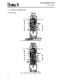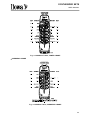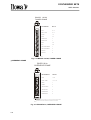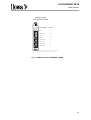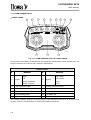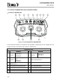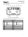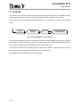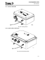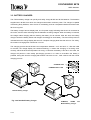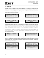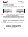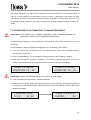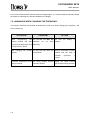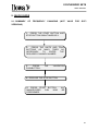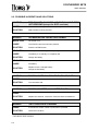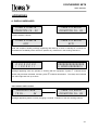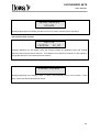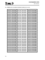
1
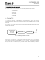
USER MANUAL
SYNTHESIZED
SETS
MULTI-FREQUENCY
SYNTHESIZED
SETS
BOGGY, COMPACT, COMBI AND BETON
Versions:
- Conventional
- GCFI
ITOWA S.A.U.
IT IS FORBIDDEN TO FULLY OR PARTIALLY REPRODUCE THIS MANUAL, WITHOUT THE
PRIOR WRITTEN AUTHORISATION FROM ITOWA.
IN THE EVENT OF INFRINGEMENT, ITOWA RESERVES THE RIGHT TO TAKE THE
ACTION IT DEEMS NECESSARY, IN ACCORDANCE WITH CURRENT LAW.
ITOWA RESERVES THE RIGHT TO MODIFY THIS MANUAL WITHOUT PRIOR
NOTIFICATION
MAUNIFIGB
REV 5
19-09-05
Approved by Engineering Manager: J. Varela
SYNTHESIZED SETS
USER MANUAL
CONTENTS:
1. INTRODUCTION
1-1
2. GENERAL RULES FOR THE CORRECT AND SAFE USE OF THE RADIO CONTROL
2-1
3. DESCRIPTION OF THE SET
3-1
3.1. TRANSMITTER
3.1.1. COMPACT TRANSMITTERS
3-1
3-2
• TOWER CRANE
3-2
• OVERHEAD CRANE
3-3
3.1.2. BOGGY TRANSMITTERS
3-5
• TOWER CRANE
3-5
• OVERHEAD CRANE
3-6
3.1.3. COMBI TRANSMITTERS
3-8
• TOWER CRANE
3-8
• OVERHEAD CRANE
3-9
3.1.4. BETON TRANSMITTERS FOR CONCRETE PUMPS
3-10
• 3-JOYSTICK TRANSMITTER
3-10
• 2-JOYSTICK TRANSMITTER
3-11
3.2. RECEIVER
3-12
3.2.1. 16-RELAY RECEIVER
3-13
3.2.2. 24 AND 32-RELAY RECEIVER
3-13
3.3. BATTERY CHARGER
4. TECHNICAL SPECIFICATIONS
3-14
4-1
4.1. GENERAL SPECIFICATIONS
4-1
4.2. TRANSMITTER
4-2
4.3. RECEIVER
4-3
4.4. ACCESSORIES
4-4
4.4.1. COMPACT, COMBI, BETON AND BOGGY
4-4
• TRANSFORMER (EXCEPT MODEL BETON)
4-4
• BATTERY CHARGER
4-4
I
SYNTHESIZED SETS
USER MANUAL
5. INSTALLATION AND START-UP
5.1. INSTALLATION OF THE RECEIVER
5-1
5.2. POWER SUPPLY OF THE RECEIVER
5-1
5.3. START-UP
5-2
6. MAINTENANCE OF RADIO CONTROL SETS
6-1
6.1. MAINTENANCE OF THE TRANSMITTER
6-1
6.2. RECEIVER MAINTENANCE
6-1
6.3. MAINTENANCE OF THE CHARGER
6-2
6.4. CHARGING THE BATTERIES
6-2
7. CHANGING THE WORKING FREQUENCY (NOT VALID FOR GCFI VERSIONS)
7-1
7.1. OPERATION MODE
7-1
7.2. PROCEDURE TO AUTOMATICALLY CHANGE FREQUENCY
7-3
7.3. PROCEDURE TO MANUALLY CHANGE FREQUENCY
7-4
7.4. CHECKING THE SELECTED CHANNEL
7-5
7.5. ANOMALIES WHEN CHANGING THE FREQUENCY
7-6
8. TROUBLESHOOTING
8-1
9. QUICK GUIDE
9-1
9.1. SUMMARY OF FREQUENCY CHANGING (NOT VALID FOR GCFI VERSIONS)
9-1
9.2. POSSIBLE INCIDENTS AND SOLUTIONS
9-2
APPENDIXES
A-1
A. DISPLAY MESSAGES
A-1
B. CHANNEL-FREQUENCY ASSIGNATION TABLES
B-1
B.1. CHANNELS IN THE 433 MHZ FREQUENCY BAND (UN 32 C.N.A.F.)
B-1
B.2. CHANNELS IN THE 868 MHZ FREQUENCY BAND (UN 39 C.N.A.F.)
B-2
C. USEFUL ADDRESSES
II
5-1
C-1
SYNTHESIZED SETS
USER MANUAL
1. INTRODUCTION
This manual is a guide to the correct use of the range of ITOWA multi-frequency remote control sets.
These sets have been specially designed for the wireless remote control of all types of electromechanical machinery.
FM frequency and FFSK codification are used for the radio transmission of control signals. The most
advanced technology and the latest generation microprocessors have been incorporated in the
electronic design. This means total safety when using the radio control.
To avoid unwanted manoeuvres, the system is provided with several safety mechanisms that are
described further on.
Manoeuvres are immediately blocked if any anomalies are automatically
detected,
The system operates in the UHF frequency band, between the 433.050 and 434.775 MHz frequencies
(UN 32 of the C.N.A.F.), or between the 868.000 and 870.000 MHz (UN 39 of the C.N.A.F.) as
stipulated in the telecommunications legislation of the I-ETS 300 220, and is certified at the time this
manual was published, in the following countries.
COUNTRIES
COMBI / BETON
BOGGY
GERMANY
D800517K
BELGIUM
RTT / TI / X84
CZECH REP.
SPAIN
CTU 2000 3 R1120
08 98 00 75
FINLAND
FRANCE
COMPACT
08 99 00 77
08 99 00 76
FI98080090
98 0170 PPL 0
GB
98 0171 PPL 0
98 0169 PPL 0
13397 13988
NETHERLANDS
-
IRELAND
ICELAND
CEPT LPD NL
-
TRA 24/5/124
IS-3025-00
ITALY
IS-3024-00
IS-3025-00
DGPGF/4/341244
PORTUGAL
ICP-009TC-99
SOUTH AFRICA
ICP-011TC-99
SATRA
SWEDEN
SWITZERLAND
ICP-010TC-99
Ue970144
U4 33
-
-
CE 0341 TYPE CERTIFICATE
Please ask ITOWA for other certifications
1-1
SYNTHESIZED SETS
USER MANUAL
GCFI VERSION
The GCFI (Intelligent Changing Frequency Management) version is provided with a smart system that
allows the equipment to randomly self-change to a free frequency, avoiding interference that usually
could stop the equipment when it is working.
IMPORTANT: EVERYTHING IN THIS MANUAL RELATED WITH THE FREQUENCY CHANGING IS
NOT VALID FOR THIS TYPE OF EQUIPMENT
1-2
SYNTHESIZED SETS
USER MANUAL
2. GENERAL RULES FOR THE CORRECT AND SAFE USE OF THE
RADIO CONTROL
For maximum safety when handling the radio control, the user must follow the rules described in this
manual.
Whenever the crane has to be manoeuvred, the radio control operator must be in a place where he
can view the whole manoeuvre being performed. If this is not possible, he should place himself where
he can see as much of the manoeuvre as he can, and coordinate with another person when he cannot
see. Never perform a manoeuvre which may be partially uncontrolled.
Do not leave the radio control transmitter on the ground or on metal blocks. If you must do so,
activate the emergency stop (STOP BUTTON) of the radio control and turn the key or selector switch
to the OFF position.
At the end of the working day, or if the radio control operator has to leave the radio control, he should
activate the emergency stop (STOP BUTTON) of the radio control, turn the key or selector switch to
the OFF position, place the battery in the charger for recharging and turn off the crane.
2-1
SYNTHESIZED SETS
USER MANUAL
3. DESCRIPTION OF THE SET
The remote controls of the SYNTHESIZED range are made up of the following elements:
• TRANSMITTER
• RECEIVER
• BATTERIES
• CHARGER
3.1. TRANSMITTER
It is a sealed push button box (IP 65 protection) in highly resistant plastic material. The manoeuvre
pushbuttons and display leds are in the front part. A housing for interchangeable batteries is provided
at the back.
As indicated the block diagram (Fig. 3.1), the transmitter consists of three parts: push buttons, control
circuit and UHF transmitter.
PUSH BUTTONS
SWITCHES
MODULATOR
TRANSMITTER
CONTROLS
Fig. 3.1 Block diagram of the transmitter.
Orders from the push buttons are picked up by the microprocessor, which draws up the FFSK signal
adding direction and control codes, and injects it to the UHF transmitter. The transmitter incorporates
the signal of this order to the carrier frequency, which after filtering, will be transmitted by the antenna.
3-1
SYNTHESIZED SETS
USER MANUAL
3.1.1. COMPACT TRANSMITTERS
• TOWER CRANE
Fig. 3.2 COMPACT 8/16, TOWER CRANE
Fig. 3.3 COMPACT 12/16, TOWER CRANE
3-2
SYNTHESIZED SETS
USER MANUAL
Fig. 3.4 COMPACT 12/24, TOWER CRANE
• OVERHEAD CRANE
Fig. 3.5 COMPACT 8/16, OVERHEAD CRANE
3-3
SYNTHESIZED SETS
USER MANUAL
Fig. 3.6 COMPACT 12/16, OVERHEAD CRANE
Fig. 3.7 COMPACT 12/24, OVERHEAD CRANE
3-4
SYNTHESIZED SETS
USER MANUAL
3.1.2. BOGGY TRANSMITTERS
• TOWER CRANE
BOGGY 8/162
TOWER CRANE
MOVEMENT
RELAY
STOP
15 - 16
START- HORN
14 - 13 - 12*
RAISE
1-9
LOWER
2-9
RIGHT
3
LEFT
4
TROLLEY BACKWARDS
5
TROLLEY FORWARDS
6
TX
BAT
Va000874
*FAST SPEED HOISTING. THIS RELAY WILL ONLY BE ACTIVATED WHEN EQUIPMENT
IS ON AND WHEN WHATEVER PUSHBUTTON FOR HOISTING IS ACTIVATED.
Fig. 3.8 BOGGY 8/162, TOWER CRANE
BOGGY 12/16
TOWER CRANE
MOVEMENT
RELAY
STOP
15 - 16
START - HORN
14 - 13
LOWER
1
RAISE
2
CRANE NORTH
3
CRANE SOUTH
4
RIGHT
5
LEFT
6
TROLLEY BACKWARDS
7
TROLLEY FORWARDS
8
AUXILIAR 1
9
AUXILIAR 2
10
TX
BAT
Va000767
Fig. 3.9 BOGGY 12/16 TOWER CRANE
3-5
SYNTHESIZED SETS
USER MANUAL
BOGGY 12/164
TOWER CRANE
MOVEMENT
RELAY
STOP
15 - 16
TX
BAT
START - HORN
14 - 13
LOWER
1 - 11
RAISE
2 - 11
CRANE NORTH
3
CRANE SOUTH
4
RIGHT
5 - 12
LEFT
6 - 12
TROLLEY BACKWARDS
7
TROLLEY FORWARDS
8
AUXILIAR 1
9
AUXILIAR 2
10
Va000875
• OVERHEAD CRANE
Fig. 3.10 BOGGY 12/164, TOWER CRANE
BOGGY 8/16
OVERHEAD CRANE
MOVEMENT
RELAY
STOP
15 - 16
START - HORN
14 - 13 - 12*
RAISE
1
LOWER
2
TROLLEY RIGHT
3
TROLLEY LEFT
4
CRANE NORTH
5
CRANE SOUTH
6
TX
BAT
*FAST SPEED HOISTING. THIS RELAY WILL ONLY BE ACTIVATED WHEN EQUIPMENT
IS ON AND WHEN WHATEVER PUSHBUTTON FOR HOISTING IS ACTIVATED.
Va000769
Fig. 3.11 BOGGY 8/16, OVERHEAD CRANE
3-6
SYNTHESIZED SETS
USER MANUAL
BOGGY 8/166
OVERHEAD CRANE
MOVEMENT
RELAY
STOP
15 - 16
START - HORN
14 - 13 - 12*
RAISE
1-9
LOWER
2-9
TROLLEY RIGHT
3 - 10
TROLLEY LEFT
4 - 10
CRANE NORTH
5 - 11
CRANE SOUTH
6 - 11
TX
BAT
*FAST SPEED HOISTING. THIS RELAY WILL ONLY BE ACTIVATED WHEN EQUIPMENT
IS ON AND WHEN WHATEVER PUSHBUTTON FOR HOISTING IS ACTIVATED
Va000876
Fig. 3.12 BOGGY 8/166, OVERHEAD CRANE
3-7
SYNTHESIZED SETS
USER MANUAL
3.1.3.COMBI TRANSMITTERS
• TOWER CRANE
5
4
6
7
9
8
10
11
12
VA000865
3
1
2
Fig. 3.13. COMBI TRANSMITTER FOR TOWER CRANE
(The manoeuvres indicated in the table are just a guideline. Manoeuvres can be changed from one
supply to another in accordance with customers’ requirements)
TOWER CRANE
Nº
MEANING
Nº
MEANING
Crane North
Right
1
Joystick
Left
Trolley Backwards
2
Joystick
Crane South
Raise
Lower
Trolley Forwards
3
Combi-Synthesized Box
4
Slewing brake push button
5
Auxiliary push button
6
Horn push button
7
Start button
8
Emergency stop button
9
On/off travelling button*
10
Low battery led
11
Transmitter led
12
On/off selector switch
*As a safety measure, bearing in mind the danger of the manoeuvre, switch no. 9 for tower crane
controls, must be in the ON position to enable the Travelling manoeuvre.
3-8
SYNTHESIZED SETS
USER MANUAL
• OVERHEAD CRANE
4
5
6
7
9
8
10
11
12
VA000866
1
3
2
Fig. 3.14. COMBI TRANSMITTER FOR OVERHEAD CRANE
(The manoeuvres indicated in the table are just a guideline. Manoeuvres can be changed from one
supply to another in accordance with customers’ requirements)
OVERHEAD CRANE
Nº
MEANING
Nº
MEANING
Lower
Trolley Right
1
Joystick
Trolley Left
Crane Forwards
2
Joystick
Raise
Crane Backwards
3
Combi-Synthesized Box
4
Auxiliary push button
5
Auxiliary push button
6
Horn push button
7
Start button
8
Emergency stop button
9
Null
10
Low battery led
11
Transmission led
12
On/off selector switch
3-9
SYNTHESIZED SETS
USER MANUAL
3.1.3. BETON TRANSMITTERS FOR CONCRETE PUMPS
• 3-JOYSTICK TRANSMITTER
5
6
7
8
9
10
11
12
13
VA000868
4
1
2
3
Fig. 3.15. 3-JOYSTICK BETON TRANSMITTER
(The manoeuvres indicated in the table are just a guideline. Manoeuvres can be changed from one
supply to another in accordance with customers’ requirements)
CONCRETE PUMP
Nº
MEANING
Nº
1
Joystick
Raise arm 4
Lower arm 4
Raise arm 3
Lower arm 3
2
Joystick
3
Joystick
Right
Left
Raise arm 1
Lower arm 1
4
Beton-Synthesized box
5
Returnable switch
reduces r.p.m.)
6
Start push button
7
Pumping/reverse returnable switch
8
Horn returnable switch
9
Auxiliary switch
10
Emergency push button
11
Low battery led
12
Transmission led
13
ON/OFF selector switch
3-10
(increases
and
MEANING
Lower arm 2
Raise arm 2
SYNTHESIZED SETS
USER MANUAL
• 2-JOYSTICK TRANSMITTER
5
6
7
8
9
10
11
12
13
VA000867
4
3
1
Fig. 3.16. 2-JOYSTICK BETON TRANSMITTER
(The manoeuvres indicated in the table are just a guideline. Manoeuvres can be changed from one
supply to another in accordance with customers’ requirements)
CONCRETE PUMP
Nº
MEANING
Nº
MEANING
Raise arm 2
Right
1
Joystick
Left
Lower arm 1
3
Joystick
Lower arm 2
Raise arm 3
Lower arm 3
Raise arm 1
4
Beton-Synthesized box
5
Returnable switch (increases and reduces
r.p.m.)
6
Start button
7
Pumping/reverse returnable switch
8
Horn returnable switch
9
Auxiliary switch
10
Emergency stop button
11
Low battery led
12
Transmission led
13
ON/OFF selector switch
3-11
SYNTHESIZED SETS
USER MANUAL
3.2. RECEIVER
The receiver unit consists of a cabinet in which the various electronic systems are located to receive
orders and activate / deactivate the corresponding relays for each manoeuvre of the crane.
The receiver unit can be divided into three blocks (Fig. 3.17), UHF receiver, control circuit and relay
circuit.
UHF
RECEIVER
CONTROL
CIRCUIT
RELAYS
TO MANOEUVRE
CONTACTORS
Fig. 3.17 Block Diagram of the receiver
The signal received by the antenna is injected to the receiver, which supplies a low frequency signal in
FFSK code to the micro-processor. The control module checks that the information received is free of
errors, and then draws up the corresponding orders to activate the relay.
In the event of anomalies in the working order of hardware or software, there are specific circuits in
the control circuit, that deactivate the radio control work manoeuvres.
For greater safety, all surveillance circuits are doubled.
3-12
SYNTHESIZED SETS
USER MANUAL
3.2.1. 16-RELAY RECEIVER
Fig. 3.18. 16-relay receiver
3.2.2. 24 AND 32-RELAY RECEIVER
VA000734
Fig. 3.19. 24 and 32-relay receiver
3-13
SYNTHESIZED SETS
USER MANUAL
3.3. BATTERY CHARGER
The ITOWA battery charger can quickly and safely charge Ni-MH and Ni-Cd batteries. The batteries
supplied are in Ni-MH, from which the charger extracts their maximum power. The charger is capable
of detecting faulty batteries, short circuits or overheating, and can recuperate batteries that have been
flat for a long time.
The battery charger has two display leds, one for power supply indicating that the unit is connected to
the mains, and the other indicating that the batteries are being charged. When the battery is inserted,
the charger starts charging without checking the battery for 20 minutes. After this time, the battery
charger checks the battery status and charges accordingly for each battery. The end of the process is
indicated when the charge display led turns off. Complete charging lasts less than 8 hours. For safety,
the maximum charging time is limited to 12 hours.
The charging process should be done at a temperature between –10ºC and 50ºC. If , after the initial
20 minutes, the charge display led continues flashing, it means that charging is not being done
correctly, either because the temperature is wrong, or because the battery is too flat. In this case, the
charger will perform a slow safety pre-charging process in to order to recondition the battery if
possible, during with time the charging led will flash. Once this is over , it will continue with the normal
charging process.
CHARGER LED
POWER SUPPLY LED
Va000805
BOGGY battery charger
Fig. 3.20. Standard battery charger
Va000810
COMPACT,
COMBI
BETON battery charger.
3-14
and
SYNTHESIZED SETS
USER MANUAL
4. TECHNICAL SPECIFICATIONS
4.1. GENERAL SPECIFICATIONS
MANUFACTURER
INVESTIGATION TOTAL WARE S.A.U.
TYPE
MULTI-FREQUENCY
FREQUENCY
ISM-BAND
NUMBER OF ORDERS
32
POSSIBILITY OF WRONG MANOEUVRE
10-18
HAMMING DISTANCE
≥6
PROGRAMMABLE CODE
16777216
ORDER RESPONSE TIME
<50 ms
ACTIVE EMERGENCY TIME
<50 ms
PASSIVE EMERGENCY TIME
1900 ms
RADIUS OF ACTION
90 metres
4-1
SYNTHESIZED SETS
USER MANUAL
4.2. TRANSMITTER
UHF UN 32 of C.N.A.F. (433.050 to 434.775 MHz)
Frequency band:
UHF UN 39 of C.N.A.F. (868.000 to 870.000 MHz)
Channelling:
25 kHz
Modulation:
FM
Transmission power:
10 mW P.R.A
Coding:
FFSK
Stability in frequency:
+ 2.5 ppm (-30ºC a +70ºC)
Attenuation of harmonics:
> 70 dB
Consumption in transmission:
80 mA
Consumption in stand-by:
< 800 µA
Power supply:
Removable battery Ni-MH, 7.2 V; 1.5 A/h
Endurance:
11 hours + 30 minutes reserve
Temperature range:
From -10ºC to +55oC
Material:
BETON
Polyamide 6-6, 15 % fibre glass
BOGGY
P.E.T.
COMBI
Polyamide 6-6, 15 % fibre glass
COMPACT
Polyamide 6-6, 30 % fibre glass
Approximate weight
BETON
1,8 kg
(without batteries)
BOGGY 8
1,1 kg
BOGGY 12
1,5 kg
COMBI
1,5 kg
COMPACT 8
0,5 kg
COMPACT 12
0,6 kg
Weight of battery
Measurements:
4-2
200 g
BETON
272 x 167 x 142 mm
BOGGY 8
400 x 80 x 65 mm
BOGGY 12
535 x 92 x 65 mm
COMBI
272 x 167 x 142 mm
COMPACT 8
265 x 80 x 68 mm
COMPACT 12
315 x 80 x 68 mm
SYNTHESIZED SETS
USER MANUAL
4.3. RECEIVER
UHF UN 32 of C.N.A.F. (433.050 to 434.775 MHz)
Frequency band:
UHF UN 39 of C.N.A.F. (868.000 to 870.000 MHz)
Sensitivity:
0.3 µV
Image frequency rejection:
>65 dB
Protection against intermodulation:
>65 dB
Adjacent channel rejection:
>65 dB
Relays:
Number of switchings:
Resistive load:
5 A + 5 A at 250 Vac or 30 Vdc
Inductive load (cosØ=0.4):
2 A at 250 Vac or 3 A at 30 Vdc
Maximum operation voltage:
380 Vac , 125 Vdc
Minimum admissible load:
10 mA at 5 Vdc
Resistive load:
106 manoeuvres 2 A at 250 Vac or 30
Vdc
Inductive load (cosØ=0.4):
106 manoeuvres 1.2A at 250 Vac or 30
Vdc
Power supply:
Max.
consumption:
48 Vac / 115 Vac / 230 Vac (-20% +15%) according to EN 60047-5-1
16 Relays: 0,7 A / 0,29 A / 0,14 A
32 Relays: 0,9 A/ 0,35 A / 0,18 A
Fuses:
Dimensions:
Transformer primary:
1 A / 230V ; 2 A / 115V ; 4 A / 48V
Transformer secondary:
4A
Safety output:
8A
16 Relays: Inside:
Outside:
32 Relays: Inside:
Weight:
Protection:
240 x 190 x 90 mm
255 x 200 x 95 mm
300 x 220 x 115 mm
Outside:
315 x 235 x 120 mm
16 Relays:
2,8 kg
32 Relays:
4,2 kg
IP 65
4-3
SYNTHESIZED SETS
USER MANUAL
4.4. ACCESSORIES
4.4.1. COMPACT, COMBI, BETON AND BOGGY
BETON sets do not have a transformer and are only supplied at 24 Vdc.
• TRANSFORMER (EXCEPT MODEL BETON)
Power supply:
230 Vac / 14 Vdc
Consumption:
3,6 VA
Weight
0,35 kg
• BATTERY CHARGER
4-4
Power supply:
14 Vdc / 24 Vdc
Consumption:
0,4 A
Power:
6W
Load intensity:
120 mA
Loading time:
8 hours
Box:
Polyamide 6-6, 15% fibre glass
Protection:
IP30
Dimensions:
73 x 69 x 72 mm
Approximate weight:
0,2 kg
SYNTHESIZED SETS
USER MANUAL
5. INSTALLATION AND START-UP
5.1. INSTALLATION OF THE RECEIVER
The control receiver should be installed in a vertical position, fastened to the structure of the machine,
with the antenna directed to the floor, and in a protected place so that when working, it does not get
knocked.
ATTENTION IT IS IMPORTANT TO PROPERLY CLOSE THE COVER OF THE RECEIVER TO
ENSURE SEALING, AS WATER LEAKING INSIDE MAY DAMAGE THE RECEIVER.
THE GUARANTEE DOES NOT COVER ANY BREAKDOWNS CAUSED BY
INCORRECTLY CLOSING THE COVER.
It is recommended to connect the set with a standard multi-cable flexible hose used to connect push
button boxes by cable. This hose will be connected to the set at one end, and the other will be
connected to a multi-pole connector identical to the one used by the machine to interconnect with a
push button box by cable. This enables the remote control or the cable control to be interchanged
simply by connecting or disconnecting the flexible hose.
ATTENTION: THE HORN RELAY SHOULD NOT BE CONNECTED TO CONTROL ANY OTHER
MANOEUVRE UNLESS OTHERWISE INDICATED.
The common manoeuvre lead should have a suitable diameter, not over 2.5 mm. nor less than 1.5
mm., nor should two 0.75 cables be placed. The common manoeuvre lead should not, under any
circumstances, be less than the diameter of the manoeuvre leads.
5.2. POWER SUPPLY OF THE RECEIVER
ATTENTION: CONNECTIONS SHOULD BE MADE SO THAT WHEN THE GENERAL SWITCH IS
TURNED OFF, THE REMOTE CONTROL RECEIVER IS ALSO TURNED OFF.
The receiver can be connected to three different alternating voltages (230 Vac, 115 Vac, or 48 Vac) ,
except the BETON receiver that connects to a set voltage of 24 Vdc, through a three-position selector
located inside the set. It is essential to ensure that the selector is in the correct position in accordance
with the voltage to be supplied to the receiver, before connecting the set. All receivers leave the
factory with the voltage pre-set at 230 Vac and 1A, but as a precautionary measure, it is advisable to
check that the voltage is correctly selected.
.A three-wire 0.75 mm2 section cable should be used to connect to the mains, connecting two cables
to voltage and the third to earth (green-yellow).
5-1
SYNTHESIZED SETS
USER MANUAL
5.3. START-UP
Once the receiver is installed and when the general switch of the machine is turned on, the LCD
display of the receiver will light up indicating the current operating channel xx, which could be from 01
to 70 or from 1 to 81 (depending on the frequency band). The receiver is now ready to operate and
receive manoeuvres from the transmitter.
ITOWA S.A RRC16
OPERATING CH.: xx
ITOWA S.A RRC32
OPERATING CH.: xx
In GCFI versions it shows:
ITOWA S.A RRC16
gcfi
ITOWA S.A RRC32
gcfi
Insert a charged battery and switch off the emergency stop button (STOP BUTTON). When the
START push button is pressed, the remote control will start to operate by turning on the stop and start
relays, and the general contactor will be interlocked. The TX ON led will turn on indicating that the
remote control is working correctly. From now on, if any push button is pressed, the corresponding
manoeuvre will be activated. The manoeuvre selected will continue to be activated while the push
button remains pressed.
The receiver display indicates the activated relays with a
deactivated relays with a 0 .
0 0 0 0 0 0 0 0
I I 0 0 0 0 I I
I
and the
0000000000000000
I I 0000 I 0000000 I i
In order to keep the radio channel free and stop the operator from leaving the machine turned on
when it is not being used, the remote control is supplied with an automatic stop system. This system
starts operating after 180 seconds from when the last manoeuvre was performed, indicating the
following message in the display:
5-2
ITOWA S.A RRC16
OPERATING CH.: xx
ITOWA S.A RRC32
OPERATING CH.: xx
ITOWA S.A RRC16
gcfi
ITOWA S.A RRC32
gcfi
SYNTHESIZED SETS
USER MANUAL
To restart the transmitter, press the START button.
To turn off the transmitter, press the STOP BUTTON.
The emergency stop is activated by pressing the STOP BUTTON. This will turn off the stop relays
and the remote control. In this situation, all relays that were on will be turned off and the initial
message will be indicated on the LCD display.
ITOWA S.A RRC16
OPERATING CH.: xx
ITOWA S.A RRC32
OPERATING CH.: xx
ITOWA S.A RRC16
gcfi
ITOWA S.A RRC32
gcfi
ATTENTION: REMEMBER THAT ACTIVATING THE STOP BUTTON IS THE SAME AS STOPPING
THE REMOTE CONTROL. THIS MEANS THAT ANY RELAY OF THE RECEIVER
THAT WAS ACTIVATED IS IMMEDIATELY TURNED OFF.
The remote control is supplied with an indicator led of the state of the battery. When it detects that the
battery is at a certain discharging level (in reserve), the BAT OK led starts to flash and the horn relay
turns on intermittently. After approximately half an hour, the transmitter turns off and the battery led
stays on permanently.
When the battery is in reserve, it is recommended to replace it with the second battery and insert the
first one to charge. Under normal conditions, the batteries can work for 11 hours plus 30 minutes
reserve time.
ATTENTION: IF THE BATTERY IS IN RESERVE, THE FREQUENCY CANNOT BE CHANGED.
PLEASE FULLY CHARGE THE BATTERIES
BEFORE USING THE EQUIPMENT FOR THE
FIRST TIME
5-3
SYNTHESIZED SETS
USER MANUAL
6. MAINTENANCE OF RADIO CONTROL SETS
The equipment you have purchased is manufactured using top quality materials ensuring perfect
working order and operation of the remote control. Similarly to all machinery or equipment, the remote
control requires minimum basic maintenance tasks that should be performed. In order to increase the
life span of the apparatus, we advise you to carefully follow these preservation and maintenance
recommendations.
As a general rule, it is advisable to periodically service the sealing devices that protect both the
receiver and transmitter from weathering. Servicing should be carried out by an ITOWA authorised
Technical Assistance Service, as incorrect sealing may cause irreparable damage to the equipment.
6.1. MAINTENANCE OF THE TRANSMITTER
ATTENTION: BEFORE HANDLING THE TRANSMITTER, TURN OFF THE GENERAL SWITCH OF
THE MACHINE
The remote control requires minimum maintenance. The good condition of the transmitter should be
checked paying special attention to joints and rubber protections of the push buttons. The silicone
caps of the push buttons should be replaced if they have been cut or damaged as a result of incorrect
use of the apparatus.
ATTENTION: DAMAGED RUBBER OF PUSH BUTTONS SHOULD BE REPLACED IMMEDIATELY,
OTHERWISE WATER MAY DAMAGE THE TRANSMITTER.
6.2. RECEIVER MAINTENANCE
Maintenance of the receiver is identical to the transmitter. The following parts must be checked:
• The antenna connection (check that it is clean and free of rust).
• The connection between the receiver and electrical equipment of the machine.
• Contacts of the manoeuvre relays.
• The correct working order of the active and passive safety circuits.
• The correct working order of the LCD display messages.
• The receiver cover should be properly sealed.
To check the working order of the active safety circuit, simply press the STOP BUTTON. The general
contactor should drop immediately.
To check the working order of the passive safety circuit, remove the battery from the transmitter and
the general contactor should drop after 1.9 seconds.
6-1
SYNTHESIZED SETS
USER MANUAL
6.3. MAINTENANCE OF THE CHARGER
Maintenance of the charger is carried out at a similar frequency to the set. The following parts should
be checked:
• Contacts and battery holders (which should be clean and free of rust).
• Springs (ensure that they are sufficiently taut to guarantee contact).
ATTENTION: IF YOU DETECT ANY ANOMALY IN THE WORKING ORDER OF THE EQUIPMENT,
IT SHOULD BE IMMEDIATELY SWITCHED OFF. REPAIRS SHOULD BE CARRIED
OUT BY A TECHNICAL SERVICE AUTHORISED BY ITOWA.
ORIGINAL ITOWA SPARE PARTS SHOULD ALWAYS BE USED.
IT IS NOT
PERMITTED TO ALTER THE SPECIFICATIONS OF THE RADIO FREQUENCY
SYSTEM OR THE CIRCUITS INVOLVED IN THE SAFETY SYSTEMS.
If you have any doubt or enquiry, contact our Technical Assistance Service or any of our authorised
technicians.
6.4. CHARGING THE BATTERIES
The batteries supplied with ITOWA equipment do not have a memory effect, meaning that they can be
charged without having to the totally flat. In order to lengthen their life span, it is recommended to use
one battery in the morning and another in the afternoon. One battery can then be charged while the
other is being used.
6-2
SYNTHESIZED SETS
USER MANUAL
7. CHANGING THE WORKING FREQUENCY (NOT VALID FOR GCFI
VERSIONS)
ATTENTION: THE WORKING FREQUENCY SHOULD ONLY BE CARRIED OUT BY AUTHORISED
STAFF.
7.1. OPERATION MODE
The system can operate in three modes:
-
Mode 1: change of frequency disabled
-
Mode 2: change of frequency in manual mode
-
Mode 3: change of frequency in automatic mode.
ATTENTION: THE EQUIPMENT IS DELIVERED WITH THE CHANGE OF FREQUENCY IN
AUTOMATIC MODE.
Changing the operation mode:
1) Unlock the STOP BUTTON and remove the key or turn off the selector switch (or battery).
2) Press the START and UNITS buttons (in COMPACT AND BOGGY models) or the START button
and right joystick in the UNITS position (in COMBI and BETON models) at the same time. Keep
them pressed and insert and turn the key or turn on the selector switch (or insert the battery). The
TX and low battery leds will flash simultaneously from one to three times, indicating the operation
mode that has been programmed, which can be:
-
Mode 1: change of frequency disabled (one flash).
-
Mode 2: change of frequency in manual mode (two flashes).
-
Mode 3: change of frequency in automatic mode (three flashes).
Repeat the sequence to go successively from mode 1 (change of frequency disabled) to mode 2 (change
of frequency in manual mode), from mode 2 to mode 3 (change of frequency in automatic mode), from
mode 3 again to mode 1, etc.
7-1
SYNTHESIZED SETS
USER MANUAL
Fig. 7.1. Elements to change frequency in COMPACT and BOGGY models.
VALIDATE
START
EMERGENCY
STOP
ON/OFF KEY
TENS
START
VALIDATE
EMERGENCY
STOP
UNITS
VA000877
UNITS
ON/OFF KEY
VA000878
TENS
Fig. 7.2. Elements to change frequency in COMBI and BETON models
To change the working frequency, select the manual or automatic frequency change mode.
7-2
SYNTHESIZED SETS
USER MANUAL
The system operates in the UHF band in frequencies from 433.050 MHz to 434.775 MHz (UN 32 of
C.N.A.F.) or from 868.000 to 870.000 MHz (UN 39 of C.N.A.F.), depending on the model you have
purchased, and meets the telecommunications and safety regulations I-ETS 300-220. There are 70 or
81 possible working channels in this frequency band (see channel assignation tables on pages. B-1
an B2).
7.2. PROCEDURE TO AUTOMATICALLY CHANGE FREQUENCY
ATTENTION: TO AUTOMATICALLY CHANGE FREQUENCY, THE AUTOMATIC CHANGE OF
FREQUENCY MODE SHOULD BE SELECTED (MODE 3)
To automatically change the working frequency, the following steps should be carried out on the
transmitter:
(The text diagrams are the messages that appear on the LCD display in the receiver)
1. If you are working with the remote control, as a safety measure, remove the transmitter battery to
disconnect the equipment.
2. Insert a charged battery. It is not possible to change frequency with a battery in stand-by.
3. Make sure the receiver is ready for operating. The following message will appear on the LCD
display, indicating that there is voltage and the last channel in which you were working:
ITOWA S.A RRC16
OPERATING CH.: xx
ITOWA S.A RRC32
OPERATING CH.: xx
ATTENTION: PLACE THE TRANSMITTER AT THE FOOT OF THE CRANE
4. If the STOP BUTTON is pressed, it should be released.
5. Press the START button. Keep it pressed and press the STOP BUTTON. The equipment selects a
new frequency automatically and the selected channel is sent to the receiver, which will display the
following messages:
CHANGING FREQ.
TO CH.:
xx_OK
ITOWA S.A RRC16
CHANNEL:
xx
7-3
SYNTHESIZED SETS
USER MANUAL
The frequency has been changed correctly. The TX ON y BAT OK indicators will have stopped
flashing. The equipment is ready to start operating. If the frequency has not been changed correctly,
repeat the process until the receiver picks up a new channel.
After changing the working channel, in order to continue operating with the radio control, release the
emergency stop button (STOP BUTTON) and press the START press button. In the receiver, the stop
and start relays will activate, and the general contactor will therefore be interlocked. At the same time,
the TX ON indicator of the transmitter will turn on indicating that the remote control is operating
correctly and all manoeuvres can be performed.
7.3. PROCEDURE TO MANUALLY CHANGE FREQUENCY
ATTENTION: TO MANUALLY CHANGE FREQUENCY, THE MANUAL CHANGE OF FREQUENCY
MODE SHOULD BE SELECTED (MODE 2)
To manually change the working frequency, the following steps should be carried out on the
transmitter:
(The text diagrams are the messages that appear on the LCD display in the receiver)
1. If you are working with the remote control, as a safety measure, remove the transmitter battery to
disconnect the equipment.
2. Insert a charged battery. It is not possible to change frequency with a battery in stand-by.
3. Make sure the receiver is ready for operating. The following message will appear on the LCD
display, indicating that there is voltage and the last channel in which you were working:
ITOWA S.A RRC16
OPERATING CH.: xx
ITOWA S.A RRC32
OPERATING CH.: xx
ATTENTION: PLACE THE TRANSMITTER AT THE FOOT OF THE CRANE
4. If the Stop Button is pressed, it should be released
5. Press the START button. Keep it pressed and press the STOP BUTTON. The TX ON and BAT
OK indicators will flash alternately. The receiver will indicate that the new working channel is on
stand-by:
WAITING RECEPT.
FREQ. CHANGING
7-4
SYNTHESIZED SETS
USER MANUAL
You now have 60 seconds to enter the new working channel. After this time, the unit will exit the
programming mode and will keep the previous channel indicating the following message:
OUT OF TIME
REMAINING CH.: XX
6. Enter the channel number, 27 for example, by pressing the master control or moving the joystick
corresponding to tens twice and seven times corresponding to units, as indicated in figures 7.1
and 7.2 and accept:
7. The selected channel is sent to the receiver, which will indicate the following messages on the
display:
CHANGING FREQ.
TO CH.:
27_OK
ITOWA S.A RRC16
OPERATING CH.: 27
The frequency has been changed correctly. The TX ON y BAT OK indicators will have stopped
flashing. The equipment is ready to start operating.
After changing the working channel, in order to continue operating with the radio control, release the
emergency stop button (STOP BUTTON) and press the START press button. In the receiver, the stop
and start relays will activate, and the general contactor will therefore be interlocked. At the same time,
the TX ON indicator of the transmitter will turn on indicating that the remote control is operating
correctly and all manoeuvres can be performed.
If you have started changing the frequency in manual mode and the pushbutton is validated without
having entered the units or tens, the telecontrol unit will automatically select channel 1.
CHANGING FREQ.
TO CH.:
01_OK
ITOWA S.A RRC16
OPERATING CH.: 01
7.4. CHECKING THE SELECTED CHANNEL
After changing the frequency, it is advisable to check that the selected channel is not already
occupied. Carry out the following operations:
1. Turn off the transmitter by pressing the STOP BUTTON.
2. If the channel occupied, the following message will appear:
BUSY CHANNEL
FREE CHANNEL: XX
7-5
SYNTHESIZED SETS
USER MANUAL
In this case the transmission channel must be changed again. It is recommended to manually change
the frequency selecting the channel indicated on the display.
7.5. ANOMALIES WHEN CHANGING THE FREQUENCY
This section describes the possible anomalies that could occur when changing the frequency, and
how to solve them.
SITUATION
When
programming
PROBLEM
ACTION
the The TX ON and BAT OK The
working channel and after indicators
do
not
that
the
battery
is
flash charged.
turning off the stop button and alternately.
turning on the on button.
After changing the working The stop and start relays are Keep the transmitter on button
channel.
not activated.
pressed until the relay is
activated
(maximum
1
minute).
Erroneous introduction of the The wrong working channel Repeat the whole process
working channel.
7-6
has been entered.
with the right working channel.
SYNTHESIZED SETS
USER MANUAL
8. TROUBLESHOOTING
If an anomaly occurs in the equipment, check the following:
1) Location of the breakdown:
Determine whether the breakdown is in the remote control equipment or in the electrical circuit of
the machine. To check this, simply connect the original pushbuttons to the machine (or from the
cabin), and check that the crane is operating properly. If the machine is working correctly, it means
that the breakdown is in the remote control, otherwise the breakdown is in the machine.
2) Checking for interferences (not valid for GCFI versions):
If the transmitter loses range or if the equipment constantly needs to be reset, there may be an
interference in the selected channel.
Check that the selected channel is free of interferences by following the procedures described in
section 7.4 (page 7-5).
3) Checking the transmitter:
Turn on the remote control by releasing the STOP BUTTON and pressing the START button. The
“TX OK” led should activate. If this indicator lights up, the problem is in the receive. If this is not
the case, check that the battery is charged. If the “BAT OK” led is flashing, it means that the
battery is on stand-by and the equipment can still transmit signals but will stop transmitting shortly.
If the “BAT OK” is on, it means that the battery is flat and must be replaced by a fully charged
battery.
If the battery is charged correctly, check that the pushbuttons operate properly. If they do, the
transmitter will have to be repaired by the Technical Assistance Service authorised by ITOWA.
4) Checking the receiver:
Check the power supply. The receiver display should be on; if it is not, check the power supply
circuit connection.
If the power supply is correct, press the START button of the transmitter and check whether the
stop and start relays are activated. If they are, check the manoeuvre fuse. If the stop and start
relays are not activated, check that there is voltage. If there is, the receiver must be repaired by
the Technical Assistance Service authorised by ITOWA.
Check that the antenna and connection to the receiver are in good condition.
ATTENTION:
ORIGINAL SPARE PARTS SHOULD BE USED IN ALL REPAIRS. ALL SAFETY
FEATURES INCLUDING THOSE OF THE TRANSMITTER AND UHF RECEIVER
SHOULD NOT BE MODIFIED.
8-1
SYNTHESIZED SETS
USER MANUAL
9. QUICK GUIDE
9.1. SUMMARY
OF
FREQUENCY
CHANGING
(NOT
VALID
FOR
GCFI
VERSIONS)
1. PRESS THE START BUTTON AND
STOP BUTTON SIMULTANEOUSLY
2.
PRESS THE UNITS AND TENS
BUTTONS AS MANY TIMES AS
NECESSARY
TO
ENTER
THE
REQUIRED CHANNEL NUMBER
3.
PRESS
PUSHBUTTON .
THE
VALIDATION
4. RELEASE THE STOP BUTTON
5. PRESS START BUTTON.
MANOEUVRES
CAN
NOW
PERFORMED.
ALL
BE
9-1
SYNTHESIZED SETS
USER MANUAL
9.2. POSSIBLE INCIDENTS AND SOLUTIONS
INCIDENT
THE CHANNEL CHANGES AND THE MACHINE DOES
NOT RESPOND (except for GCFI versions)
CAUSE
The selected working channel is occupied by another transmitter
SOLUTION
Select another working channel
INCIDENT
NO MANOEUVRE CAN BE PERFORMED
INDICATION
TX ON led is on.
CAUSE
The START button has not been pressed
SOLUTION
Press the START button
INDICATION
It is not possible to change the frequency *
CAUSE
The battery is on standby or completely flat
SOLUTION
Change the battery
INDICATION
Low battery led is permanently on
CAUSE
Flat battery
SOLUTION
Replace it with a charged battery
Charge the flat battery
INCIDENT
THE TRANSFER MANOEUVRE DOES NOT WORK
CAUSE
Transfer switch of the transmitter is in the OFF position
SOLUTION
Turn the switch ON
INCIDENT
THE TRANSMITTER HAS LIMITED RANGE
CAUSE
The antenna is disconnected, broken or in bad condition
SOLUTION
Replace the antenna, contact the Technical Service Assistance
INCIDENT
THE TX ON LED IS FLASHING
CAUSE
A manoeuvre master control or pushbutton is pressed
SOLUTION
Check their condition
_______________________________
* Not valid for GCFI versions.
9-2
SYNTHESIZED SETS
USER MANUAL
APPENDIXES
A. DISPLAY MESSAGES
ITOWA S.A RRC16
OPERATING CH.: xx
ITOWA S.A RRC32
OPERATING CH.: xx
In GCFI versions, it shows:
ITOWA S.A RRC16
gcfi
ITOWA S.A RRC32
gcfi
Initial and reception standby message, appearing after start-up or when on standby for a manoeuvre.
It indicates the availability of the receiver to perform any manoeuvre in the working channel:xx.
0 0 0 0 0 0 0 0
I I 0 0 0 0 I I
0000000000000000
I I 0000 I 0000000 I i
Message appearing when the operator is working with the equipment. Symbol
certain relay has been activated, and the symbol
0
I
indicates that a
indicates deactivation. The relays are numbered
from left to right and from up to down.
* Not valid for GCFI versions.
changing freq.
to CH.:
xx
ITOWA S.A RRC16
OPERATING CH.: xx
Messages appearing before correctly changing a channel. Indication of the new working channel.
A-1
SYNTHESIZED SETS
USER MANUAL
* Not valid for GCFI versions.
WAITING RECEPT.
FREQ. CHANGING
This message appears in the operation to change the working channel, when the receiver is on
standby for the operator to enter the new working channel in the transmitter. Once this message
appears, you have 60 seconds to enter the new working channel. If it is not entered, the receiver will
exit the programming mode and the equipment will remain in the original channel. The following
message then appears:
* Not valid for GCFI versions.
BUSY CHANNEL
FREE CHANNEL: XX
Message indicating the existence of another device near the same operation frequency as the
equipment. In this situation, the receiver offers another possible free channel as a solution.
EMERGENCY RELAY
FAILURE N.:
XX
Message appearing on the display if a fault occurs in one of the two guided stop relays.
A-2
SYNTHESIZED SETS
USER MANUAL
SERIAL DRIVERS
FAILURE
Message appearing on the display if a fault occurs in any of the control drivers of the relays.
* Not valid for GCFI versions.
WRITING
CHANNEL: XX_OK
Message appearing on the display when the receiver locates its equipment code and working
frequency after scanning all the channels. This situation occurs when the receiver is in the frequency
change process but is not receiving the new channel.
E2PROM FAILURE
Message appearing in the display if there is a fault in the E2PROM memory of the receiver. In this
case, contact the authorised technical service.
A-3
SYNTHESIZED SETS
USER MANUAL
B. CHANNEL-FREQUENCY ASSIGNATION TABLES
B.1. CHANNELS IN THE 433 MHz FREQUENCY BAND (UN 32 C.N.A.F.)
Channel 1: 433.050 MHz
Channel 25 : 433.650 MHz Channel 49 : 434.250 MHz
Channel 2: 433.075 MHz
Channel 26 : 433.675 MHz Channel 50 : 434.275 MHz
Channel 3: 433.100 MHz
Channel 27 : 433.700 MHz Channel 51 : 434.300 MHz
Channel 4: 433.125 MHz
Channel 28 : 433.725 MHz
Channel 5: 433.150 MHz
Channel 29 : 433.750 MHz Channel 53 : 434.350 MHz
Channel 6: 433.175 MHz
Channel 30 : 433.775 MHz Channel 54 : 434.375 MHz
Channel 7: 433.200 MHz
Channel 31 : 433.800 MHz Channel 55 : 434.400 MHz
Channel 8: 433.225 MHz
Channel 32 : 433.825 MHz Channel 56 : 434.425 MHz
Channel 9: 433.250 MHz
Channel 33 : 433.850 MHz Channel 57 : 434.450 MHz
Channel 10: 433.275 MHz
Channel 34 : 433.875 MHz Channel 58 : 434.475 MHz
Channel 11: 433.300 MHz
Channel 35 : 433.900 MHz Channel 59 : 434.500 MHz
Channel 12: 433.325 MHz
Channel 36 : 433.925 MHz Channel 60 : 434.525 MHz
Channel 13: 433.350 MHz
Channel 37 : 433.950 MHz Channel 61 : 434.550 MHz
Channel 14: 433.375 MHz
Channel 38 : 433.975 MHz Channel 62 : 434.575 MHz
Channel 15: 433.400 MHz
Channel 39 : 434.000 MHz Channel 63 : 434.600 MHz
Channel 16: 433.425 MHz
Channel 40 : 434.025 MHz Channel 64 : 434.625 MHz
Channel 17: 433.450 MHz
Channel 41 : 434.050 MHz Channel 65 : 434.650 MHz
Channel 18: 433.475 MHz
Channel 42 : 434.075 MHz Channel 66 : 434.675 MHz
Channel 19: 433.500 MHz
Channel 43 : 434.100 MHz Channel 67 : 434.700 MHz
Channel 20: 433.525 MHz
Channel 44 : 434.125 MHz Channel 68 : 434.725 MHz
Channel 21: 433.550 MHz
Channel 45 : 434.150 MHz Channel 69 : 434.750 MHz
Channel 22: 433.575 MHz
Channel 46 : 434.175 MHz Channel 70 : 434.775MHz
Channel 23: 433.600 MHz
Channel 47 : 434.200 MHz
Channel 24: 433.625 MHz
Channel 48 : 434.225 MHz
Channel 52 : 434.325 MHz
B-1
SYNTHESIZED SETS
USER MANUAL
B.2. CHANNELS IN THE 868 MHz FREQUENCY BAND (UN 39 C.N.A.F.)
B-2
Channel 1: 868.000 MHz
Channel 28 : 868.675 MHz
Channel 55 : 869.350 MHz
Channel 2: 868.025 MHz
Channel 29 : 868.700 MHz
Channel 56 : 869.375 MHz
Channel 3: 868.050 MHz
Channel 30 : 868.725 MHz
Channel 57 : 869.400 MHz
Channel 4: 868.075 MHz
Channel 31 : 868.750 MHz
Channel 58 : 869.425 MHz
Channel 5: 868.100 MHz
Channel 32 : 868.775 MHz
Channel 59 : 869.450 MHz
Channel 6: 868.125 MHz
Channel 33 : 868.800 MHz
Channel 60 : 869.475 MHz
Channel 7: 868.150 MHz
Channel 34 : 868.825 MHz
Channel 61 : 869.500 MHz
Channel 8: 868.175 MHz
Channel 35 : 868.850 MHz
Channel 62 : 869.525 MHz
Channel 9: 868.200 MHz
Channel 36 : 868.875 MHz
Channel 63 : 869.550 MHz
Channel 10: 868.225 MHz
Channel 37 : 868.900 MHz
Channel 64 : 869.575 MHz
Channel 11: 868.250 MHz
Channel 38 : 868.925 MHz
Channel 65 : 869.600 MHz
Channel 12: 868.275 MHz
Channel 39 : 868.950 MHz
Channel 66 : 869.625 MHz
Channel 13: 868.300 MHz
Channel 40 : 868.975 MHz
Channel 67 : 869.650 MHz
Channel 14: 868.325 MHz
Channel 41 : 869.000 MHz
Channel 68 : 869.675 MHz
Channel 15: 868.350 MHz
Channel 42 : 869.025 MHz
Channel 69 : 869.700 MHz
Channel 16: 868.375 MHz
Channel 43 : 869.050 MHz
Channel 70 : 869.725 MHz
Channel 17: 868.400 MHz
Channel 44 : 869.075 MHz
Channel 71 : 869.750 MHz
Channel 18: 868.425 MHz
Channel 45 : 869.100 MHz
Channel 72 : 869.775 MHz
Channel 19: 868.450 MHz
Channel 46 : 869.125 MHz
Channel 73 : 869.800 MHz
Channel 20: 868.475 MHz
Channel 47 : 869.150 MHz
Channel 74 : 869.825 MHz
Channel 21: 868.500 MHz
Channel 48 : 869.175 MHz
Channel 75 : 869.850 MHz
Channel 22: 868.525 MHz
Channel 49 : 869.200 MHz
Channel 76 : 869.875 MHz
Channel 23: 868.550 MHz
Channel 50 : 869.225 MHz
Channel 77 : 869.900 MHz
Channel 24: 868.575 MHz
Channel 51 : 869.250 MHz
Channel 78 : 869.925 MHz
Channel 25: 868.600 MHz
Channel 52 : 869.275 MHz
Channel 79 : 869.950 MHz
Channel 26: 868.625 MHz
Channel 53 : 869.300 MHz
Channel 80 : 869.975 MHz
Channel 27: 868.650 MHz
Channel 54 : 869.325 MHz
Channel 81 : 870.000 MHz
SYNTHESIZED SETS
USER MANUAL
C. USEFUL ADDRESSES
ITOWA S.A.U.
C/ Faraday, 159
08224 TERRASSA (BARCELONA)
Telf +34-93.733.98.50 Fax +34-93.789.13.51
e-mail: [email protected]
http://www.itowa.com
C-1
DCUNIFIGB – Rev. 1
EC – DECLARATION OF CONFORMITY
The manufacturer:
ITOWA S.A
C/ Faraday, 159
E-08224 Terrassa
Barcelona, España
Tel.: +34 93 733 98 50
Fax: +34 93 789 13 51
According with the requirements of the R&TTE 1999/05/EC Annex III declares under its
responsibility that the radio remote control equipment designated as:
COMPACT, BOGGY, COMBI and BETON
Are in conformity with the following European Directives:
•
•
98/37/EC (June, 22nd 1998) : Safety of machinery.
o
With the standard EN 954-1 (1996) type CLASS III concerning the main requirements of health and
safety to the design and the construction of machines.
o
With the standard EN 60204-32 (1998) concerning the safety of machinery; electrical equipment of
machines; Part 32 : Requirements for hoisting machines.
o
With the standard EN 13557 (2003) concerning cranes; controls and control stations.
99/05/EC (March, 9th 1999) : Radio and Telecommunications Terminal Equipment (R&TTE).
o
With the standard EN 60215 (1989) concerning the safety requirements for radio transmitting
equipment.
o
With the standard EN 60215/A2 (1994) concerning the safety requirements for radio transmitting
equipment.
o
With the standard EN 301 489-3 v1.4.1 concerning the electromagnetic compatibility and Radio
spectrum Matters (ERM); Electromagnetic Compatibility (EMC) standard for radio equipment and
services; PART 3 Specific conditions for Short-Range Devices (SRD) operating on frequencies
between 9 kHz and 40 GHz.
o
With the standard EN 300 220-3 v1.1.1 concerning the electromagnetic compatibility and radio
spectrum matters (ERM); Short Range Devices (SRD); Radio equipment to be used in the 25 MHz
to 1.000 MHz frequency range with power levels ranging up to 500 mW; Part 3 : Harmonized EN
covering essential requirements under article 3.2 of the R&TTE Directive.
Signatory :
Name : Ramón Faure
Function : Technical Manager
Place and date : Terrassa, March 07th 2005
Signature
GUARANTEE
ITOWA equipment have one year guarantee. This guarantee will be effective at its
departure from our warehouse.
Guarantee includes replacement or repair of defective components, as well as
labour
Guarantee is valid with the units placed at ITOWA’s facilities in Terrassa, Spain.
Equipment’s guarantee will not be valid in following conditions:
• Wrong installation.
• Detected damages due to an unsuitable closing.
• Non-authorized person manipulation.
• Inappropriate or misuse of the equipment.
• Damages generated by external reasons out of our responsibility like surges,
fires, etc.
• Damages generated by natural phenomenon (lightning, earthquakes, flooding,
etc.)
Guarantee outlined herein does not include piles .
MAPIGGB – Rev. 2