1
Si42-107
Service
Manual
Packaged Air Conditioners
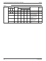
Duct Connection Type
(High Static Pressure Application)
FD(Y)-K(A) Series
[Applied Models]
Cooling Only
Heat Pump
Si42-107
Packaged Air Conditioners
Duct Connection Type
(High Static Pressure
Application)
FD(Y)-K Series
Packaged Air Conditioners Duct Connection Type
(High static Pressure Application
FD-K Series — Cooling Only — ...................... 1
Part 1 Model Name and Power Supply ......................................... 3
Part 2 Functions ............................................................................ 7
Part 3 Specifications .................................................................... 9
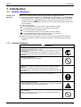
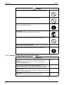
!
!"# !
$!"# Part 4 Remote Controller (Optional Accessories)...................... 15
%
$
%& $
'()*'+,-. +
/0'()*'+,. 1
'()*'+,2.!
30/0(
Part 5 Field Piping and Wiring .................................................... 23
030 Table of Contents
i
Si42-107
$
/!-*4!*4!* /!$*4! *4!* 1
/*4!*-
'+54!!545 -1
'5!$*
'! *4'!* !
Part 6 Function and Operation ................................................... 55
% $
5$
%5 +
%6 %6)/,*7',5.
%6)/,*7'5,*.$!
- $
- 5$
- %5 $
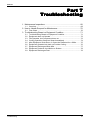
Part 7 Troubleshooting ............................................................... 67
8
$
% $
""'98
+!
6 +!
- :;6029(+
-
-
--
-
-$
-+
-
-1
:;6029( +
9(% +
%4;( +0%;(( +
9(6/4
;'36+
9(%;0 +$
9(/
60368 ++
9(
&<6=+
9(/
60/+1
Part 8 Removal Procedure .......................................................... 81
'+5> '(0
'(%58 '(
2 '((
Part 9 Appendix........................................................................... 87
0/0(
0%
30/0( 1!
!"# 1!
$!"# 1+
ii
Table of Contents
Si42-107
Packaged Air Conditioners Duct Connection Type
(High static Pressure Application)
FDY-K(A) Series — Heat Pump —.............. 107
Part 1 Model Name and Power Supply ..................................... 109
8<(
!
"06
:!
Part 2 Functions ........................................................................ 113
Part 3 Specifications ................................................................ 115
$
*!"# $
*$!"# *!"# !
*$!"# Part 4 Remote Controller .......................................................... 125
'( $
3'(2'$
3'(2'$+
- 3'(2'$ Part 5 Field Piping and Wiring .................................................. 129
030 -!
/>!$4! 4!*). -!
/>?!*). '>!*5 $
'>!!*5?'>!*5 Part 6 Field Setting ................................................................... 151
86
)'8
?'.
0 - #@<0)A!"8%. +
0
08
52 - /
64B(2 $
- '
:;$
Table of Contents
iii
Si42-107
- (0
% $
-- 8
80$
Part 7 Function and Operation ................................................. 165
% $$
5$$
%5 $+
%
6)'>!*5. $
0?0(/% $
"0 +!
- %
6)'>!!4!*5. +
- 0?0(/% +
- "0 +
+$
5+$
%5 +1
:6(:('
:; :6(:('
:; $ / $ 5/>!$A!*).
$ %5'>!*58 $- %5'>!!C!*58 1+
Part 8 Troubleshooting ............................................................. 205
8
!+
%(% !+
""'98
!
6 !
- :;6029(
-
-
--
-
-$
-+
-
-1
-!
-
:;6029( 9(% %4;( 0?"0%;(( 9(6/4
;'36
9(%;0 +
9(%;"0 1
9(/
60368 9(
&<6=
9(/
60/'(&//D D ,/0;'( :6<:%<?::2
,/0;3'($
- '(/8
1
,/0;&/-!
:;60;&/:65E -!
:;60;&/:6%5E2 -
$ :;60;'(/?&//-
$ (;-
$ 8
&//:;--
iv
Table of Contents
Si42-107
$$
$
$$
$+
$
$1
$!
$
$
$$
$
$$
$+
$
$1
$!
$
$
52 -
8
"
60:(( -$
8
:((-+
8
'(:6( /
-1
/
!
%52 "06()".8
&()&.8
8
F /
60:(8
8
"06
6$
8
&
6 +
8
%:(( 8
/
60:((1
8
"
60:(( !
6@8
'6
8
:()2%5.8
:(
)25'(. $
$- :(28'(
;'(+
$ 0
6
Part 9 Appendix......................................................................... 261
0/0($
?%5 $
30/0($+
Index
5/>,*8 $+
5/>,*8 +
%5 +
30)/>!$?! ?!*)..+
30)/>?!*)..+1
............................................................................................. i
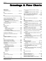
Drawings & Flow Charts ............................................................... iii
Table of Contents
v
Si42-107
vi
Table of Contents
Si42-107
Introduction
! 260
;
0=
! :6
(
G
HG
H:6
GH
(
(
6
6I6
:6G
H(
(
6:64;;6
(
;;
! ;6
0(
:6(;
(6
6
(;
:6
0(66(6
6(;
:6(;
6;
:66;(
66(;
:6(;
6(;=4
:6
66(;
! 6=
(4;
66
9((46
06
6
(
2
6
;0(60
=;
(;069(
3=069(6
6=
69(
6
06
4
6
60
6
9(
600
6006=4
66
60000
:600
;
36
06
606
(6
4600
(,
60(06
(4600
00(
6
6066
4
I
600=06=46:6
00
0
06
(
:6,
606,0
6
(6
2
606
(;
0=
60
6
=
/6
;0000006
;0
0000006
;069(
6
=
vii
Introduction
Si42-107
/6
(66
3=069(66
6
=
/
6
;60
36066
6
=
26006069(6(
4
6
=
26
606
;6
0
69(
:66064
I
/66(0
:66
6
2
6
=6600
6
;
0=
3=066600
6
;
56,
506
(
0
26
6
;(
=<((6
9(
:6
6
=4
60
36
069(4(=666
06660669(
66
066
=
469(
I
26
;06
(
6((
6
9(40I
26
6((
(
6
(4
I
viii
0
0
Si42-107
Introduction
2
69(46
6
6
9(460
06
(6
0
=
(
=
6
=
26
;
;6
8=6
6
;66
06
;6
(
(
60
36
06
;;64(=
66(
(;
6
;
6
(46(
6
=4
60
/(0(6
;
/(0(
;
6
=
06(6
;46006
;
(06
;
/(0666
0)'.60
(
600(4
6064
09((0I
600=4;
6=;
60060
60004(=66
0=
6=
;
6=(;4;
((,
6
4600
(=06(:6006(4;
0
06
(4
6664
0
36
06
;6(
4;
6;
6(0
66
;4
((
=0;=
(
06
64
6
=
/69(
66;
(;;0=
(;;0=(64
26
=06(
0
6
=04
6( 6
6
=(=66
;046
606
606
4
6
=
6
;6
64;
6(
/(0
;
6
=4
6
0
ix
Introduction
Si42-107
/I
;
;466(
66
4
6
=4
60
6
=6(
4
6
6
((
(
604
6
=
6((6
4
((
640
I
6
=600469(0
(00
6
=
2(6
64(=
66
86(606
6
=
2
6
=6066
0
66(6
66
(:6(0
6
;6;;J
:
(
<
/
G
H660664606
(4((09(440
6).
30
G0H660I
'
G
H066
6;
6(466?6(
GH(6;4;(
6;;64
6
=
x
Si42-107
Packaged Air Conditioners
Duct Connection Type
(High static Pressure
Application)
FD-K Series
— Cooling Only —
Model Series
Class
Indoor Units
3HP
4HP
FD03K FD04K
5HP
6HP
8HP
10HP
FD05K FD06K FD08K FD10K
15HP
20HP
FD15K
FD20K
Outdoor Units R71FU R100FU R125FU RU06K RU08K RU10K RU08K×2 RU10K×2
1
Si42-107
2
Si42-107
Part 1
Model Name and
Power Supply
Model Name and Power Supply
3
Power Supply
Si42-107
!"
!"
(;
>
4
/!-*>
%
'+5>
-φ- !AF!"#
).
/!*>
/!*>
'!!5>
'5>
/!$*>
/! *>
'5!$*>
'5! *>
/!*>
/*>
'5!*>
'5! *>K
F&
/!*>
/!-*F&
'5!*>K
'+5F&
φ!F$!"#
:&
/!*F&
/!*:&
'!!5F&
'5:&
-φ!F$!"#
/!$*:&
/! *:&
'5!$*:&
'5! *:&
/!*:&
/*:&
'5!*:&
'5! *:&K
/!*:&
'5!*:&K
Model Name and Power Supply
Si42-107
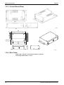
External Appearance
#$"%
#$"%
&
Model Name and Power Supply
5
External Appearance
6
Si42-107
Model Name and Power Supply
Si42-107
Part 2
Functions
Functions
7
Function
Si42-107
'
'
(
%
;%
'
I;
60&06
8
,
(
6
60
;
"J0
8
/
"06
:
/,*
"
")
608.
(
"
")*.
Functions
Si42-107
Part 3
Specifications
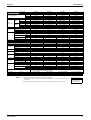
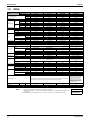
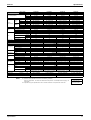
!
!"# !
$!"# Specifications
9
Specifications
Si42-107
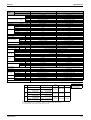
()*
&
+"
!0
0
5
%
5
&9
@
/
&9
@
/
=3
2?6
=
?6
M
((
((
((
((
((
((
/(
306
&
:
'K0K
6
:
/
'
8%
"K3K/
(P
(Q?(
(
(("%
=3
((
=0
',(-.
0'.
+4 !!
+4!!!
!!,!
φ1)2#0.
φ1)2#0.
-?2
φ1).
φ1).
φ$!)".
',(-.
KK!
!-
$
1
+
!
!K$!K !
0'.
:
(
'0
'0
%
',(-.
',(-.
(('.
'.
!
!
-+4+!!
+4$!!
14!!
4!!!
!!,!
!!,!
φ1)2#0.
φ1)2#0.
φ1)2#0.
φ1)2#0.
-?2
-?2
φ1).
φ1).
φ1).
φ1).
φ$!)".
φ$!)".
',(-.
',(-.
)3&",O:;.
KK!
KK!
!-+!
!-+!
2/
-!
$
4!1
4$!
1
1
!
!+
!K1!!K !
!K1!!K !
1
+
(('.
'.
"(
'
0:
8
<
8%
8
60
8
60
=3
"--R/2<
-!
"-$R/2<
-
=0
5<%-@
$-
:
$-
'K0K
6
(P
'0
&06
(
'0
8&06
(
8"06/
(
:
8
(Q?(
'!?$!"#
(
8%
3
K-$K!
!$
!)9&06+!(.
-!
B8
$
4$!
!
KK!
!1+1
KK!
!1+1
:;
!)9&06+!(. !)9&06+!(.
-!
-!
B8K
B8K
!
+
4 -4!+
+7-
+7$!
:6(
%84'F)(.
8
)(.%
'8
/
/(
306
/0<
"K3K/
KK!
!1
4 -$
1
!+
!K4-!K !
+1
(/-.
6
"(
:
B:!!2,>
N
'
10
"-$R/2<
',(/-.
(/-.
+
14!!
4!!!
!!,!
φ1)2#0.
φ1)2#0.
-?2
φ1).
φ1).
N
',(/-.
((
=0
$K
!K-+!
4K !K-+!
!1
/!!!-
4K !K-+!
!
! <(
0
;60
J
'(J+L/241L324%(J-L/290J(
)"#.
! 0
6
6
(6
-!)
60(.
5<%@//,*
$
)3
&",O
:;.
K$!K!
$
!)9&06+!(.
-!
B8
!
-4 7$
:6(
(%
84"06
64&
64%'
)(
8.4'6
4
4-K !K-!
/!!$ 1
(
=
?6S=3K $!
2?6S=3K-
(S(Q?(K--
Specifications
Si42-107
Specifications
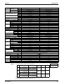
&
',(-.
',-.
',(-.
(-.
(1-.2
(-.2
=3
1+
$
1!0
2?6
!4!!
$$4!!!
!4!!
=
?6
4!!
4 !!
4!!!
M
!!,!
!!,!,!
!!,!,!
Kφ+)2#0.
Kφ1)2#0.
φ1)2#0.
&9
((
Kφ)2#0.
Kφ- )2#0.
@
((
φ- )2#0.
5
/
((
-?2
2
2
0
Kφ+)2#0.
Kφ1)2#0.
φ1)2#0.
&9
((
% @
Kφ)2#0.
Kφ- )2#0.
((
φ- )2#0.
5
/
((
N
N
N
',(-.
',-.
',(-.
:
)3&",O:;.
'K0K
6
-KK!
-KK!
-K$K!
-K$K!
(P
!!
!+ !11
:
/
2/
(Q?(
$
-$
$$
'
(
4!!
41-!
4 !!
4 $!
!
!
(("%
8%
=3
-+
/(
"K3K/
((
!!K4-!K !
!!K4--!K !
$K4$!K !
$K41 !K !
306
=0
1!
$
+
&
(1-.
(-.
(1-.2
(-.2
36
:
"(
:
(
8
B:$/>,
B:--/>,
K)B:$/>,.
K)B:--/>,.
8%
=3
+
1
K+
K1!
8
'
'0
60
=0
!)60(.
$)60(.
K!)60(. K$)60(.
8
5<%@//,*
'0
%
60
K!
K!
:
)3&",O:;.
'K0K
6
K!K!
K!K!
K)K!K!.
K)K!K!.
(P
+
1+
K+
K1+
'0
:;
&06
(
'0
8&06
(
!)9&06+!(. !)9&06+!(. !)9&06+!(. !)9&06+!(.
8"06/
(
-!
-!
-!
-!
:
8
"
"
:"
:"
(Q?(
!
+
K!
K+
'!?$!"#
(
41
$4++
K41
K$4++
8%
3
-!71!
-!71!
K)-!71!.
K)-!71!.
:6(
(%84"06
64%')(
/
8.4'6
4
/(
"K3K/
((
4!K4 !K$1!
4!K4 !K$1!
K)4!K4 !K$1!.
K)4!K4 !K$1!.
306
=0
++
1!
K++
K1!
/0<
/!!$ 1
/!! $++
+"
Specifications
',(1-.
(1-.
-4!!!
!41!!
!!,!
φ+)2#0.
φ)2#0.
-?2
φ+)2#0.
φ)2#0.
N
',(1-.
! <(
0
;60
J
'(J+L/241L324%(J-L/290J(
)"#.
! 0
6
6
(6
(
=
?6S=3K $!
2?6S=3K-
(S(Q?(K--
11
Specifications
Si42-107
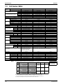
/()*
&
+"
!0
0
5
%
5
&9
@
/
&9
@
/
=3
2?6
=
?6
M
((
((
((
((
((
((
/(
306
&
:
'K0K
6
:
/
'
8%
"K3K/
(P
',(-3%
0'3%
$
14!!
+4!!
!!,!
φ1)2#0.
φ1)2#0.
-?2
φ1).
φ1).
φ$!)".
',(-3%
KK!
!-
(Q?(
(
(("%
=3
((
=0
$
1+
+
!
!K$!K !
0'3%
F&
:&
=3
"--R2
N
-
"-$R2
N
=0
)60(.
1)60(.
5<%-@
$-
:
(
'0
'0
%
',(-3%
',(-4%
(('3%
'4%
4-!!
4 !!
!4!!
-4-!!
!!,!
!!,!
φ1)2#0.
φ1)2#0.
φ1)2#0.
φ1)2#0.
-?2
-?2
φ1).
φ1).
φ1).
φ1).
φ$!)".
φ$!)".
',(-3%
',(-4%
)3&",O:;.
KK!
KK!
!-+!
!-+!
2/
-!
$
4!1
4$1
1
!
!+
!K1!!K !
!K1!!K !
$
+
(('3%
'4%
"(
'
0:
8
<
8%
8
60
8
60
:
-)60(.
$-
'K0K
6
(P
'0
&06
(
'0
8&06
(
8"06/
(
:
8
(Q?(
'!?$!"#
(
8%
3
K-$K!
!$
!)9&06+!(.
-!
B8
41
!
KK!
!1+1
KK!
!1+1
:;
!)9&06+!(. !)9&06+!(.
-!
-!
B8:
B8:
1
1
-4+
-41
1!7$!
1!7 !
:6(
%84'F)(.
8
)(.%,'8
/
/(
306
/0<
"K3K/
KK!
!1
4 -
1
!+
!K4-!K !
+1
(/-4%
36
"(
:
N
B:1!2
N
'
12
N
"-$R/2&
$!
',(/-4%
(/-4%
+
14!!
4!!!
!!,!
φ1)2#0.
φ1)2#0.
-?2
φ1).
φ1).
N
',(/-4%
((
=0
$K
!K-+!
+
4K !K-+!
+
/!! $!
4K !K-+!
!
! <(
0
;60
J
'(J+L/241L324%(J-L/290J(
)"#.
! 0
6
6
(6
-!)
60(.
5<%@//,*
$
)3
&",O
:;.
K$!K!
$
!)9&06+!(.
-!
B8
!
-4 !!7!!
:6(
(%
84"06
64&
64%'
)(
8.4'6
4
4-K !K-!
/!!$ !
(
=
?6S=3K $!
2?6S=3K-
(S(Q?(K--
Specifications
Si42-107
Specifications
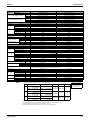
&
',(-4%
',-4%
',(-4%
(-4%
(1-4%2
(-4%2
=3
1+
$
1!0
2?6
!4!!
$$4!!!
!4!!
=
?6
4!!
4 !!
4!!!
M
!!,!
!!,!,!
!!,!,!
Kφ+)2#0.
Kφ1)2#0.
φ1)2#0.
&9
((
Kφ)2#0.
Kφ- )2#0.
@
((
φ- )2#0.
5
/
((
-?2
2
2
0
Kφ+)2#0.
Kφ1)2#0.
φ1)2#0.
&9
((
% @
Kφ)2#0.
Kφ- )2#0.
((
φ- )2#0.
5
/
((
N
N
N
',(-4%
',-4%
',(-4%
:
)3&",O:;.
'K0K
6
-KK!
-KK!
-K$K!
-K$K!
(P
!!!
!+ !11!
:
/
2/
(Q?(
$
-$
$$
'
(
4!!
411
4 !!
4 $!
!
!
(("%
8%
=3
-+
/(
"K3K/
((
!!K4-!K !
!!K4--!K !
$K4$!K !
$K41 !K !
306
=0
1!
$
+
&
(1-4%
(-4%
(1-4%2
(-4%2
36
:
"(
:
8
B:-$/,
B:-!!/,
K)B:-$/,.
K)B:-!!/,.
(
<
N
N
N
N
8%
=3
+
K
K+
8
'
'0
60
=0
!)60(.
$)60(.
K!)60(. K$)60(.
8
5<%@//,*
'0
%
60
!
!
:!
:!
:
)3&",O:;.
'K0K
6
K!K!
K!K!
K)K!K!.
K)K!K!.
(P
+
1+
K+
K1+
'0
:;
&06
(
'0
8&06
(
!)9&06+!(. !)9&06+!(. !)9&06+!(. !)9&06+!(.
8"06/
(
-!
-!
-!
-!
:
"
"
:"
:"
8
(Q?(
$!
1!
K$!
K1!
'!?$!"#
(
4$
$4+!+
K4$
K$4+!+
8%
3
-!71!
-!71!
K)-!71!.
K)-!71!.
:6(
(%84"06
64%')(
/
8.4'6
4
/(
"K3K/
((
4!K4 !K$1!
4!K4 !K$1!
K)4!K4 !K$1!.
K)4!K4 !K$1!.
306
=0
+$
K+$
K
/0<
/!!$ !
/!! $+
+"
Specifications
',(1-4%
(1-4%
-4!!!
!41!!
!!,!
φ+)2#0.
φ)2#0.
-?2
φ+)2#0.
φ)2#0.
N
',(1-4%
! <(
0
;60
J
'(J+L/241L324%(J-L/290J(
)"#.
! 0
6
6
(6
(
=
?6S=3K $!
2?6S=3K-
(S(Q?(K--
13
Specifications
14
Si42-107
Specifications
Si42-107
Part 4
Remote Controller
(Optional Accessories)
%
$
%& $
'()*'+,-. +
/0'()*'+,. 1
'()*'+,2.!
30/0(
Remote Controller (Optional Accessories)
15
Optional accessories
Si42-107
&"
&
%
'(
'(=
8
6
:
/0:
-8:(
*
16
36-8
:(3:
;8
/!-*4!*>4F&
/!*4!$*4! *4!* /*4!*>4:&
>4:&
*'+,-
*'+,<%:.
*'+,2
<%:.
*'+,
*'+,
<%:.
N
36-8
:(
N
*:1
/:!+
!!,!M
!!,!,!M
- *'+,2&
(
4-((*:1
6
00
(
Remote Controller (Optional Accessories)
Si42-107
Optional accessories
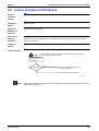
5""6-078
*'+,-
6046
=
5""
)"
Remote Controller (Optional Accessories)
17
Optional accessories
Si42-107
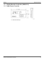
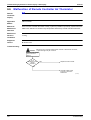
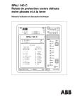
"969$8
150
80
15
220
4-Ø6HOLE
200
60
240
(P1392)
:"
:""; 56155!"":<":"=8
:":!#$
18
Remote Controller (Optional Accessories)
Si42-107
Optional accessories
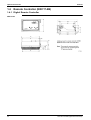
,"5""6-078
,"5""
%>&!"":;568
Remote Controller (Optional Accessories)
19
Optional accessories
Si42-107
5""6-0798
,"5""
-079
20
Remote Controller (Optional Accessories)
Si42-107
Optional accessories
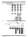
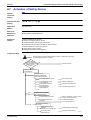
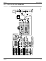
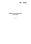
",5
-07
B C
D
A
E
~
~
~
~
B
C
A
D
~
~
~
~
B
C
A
3
THERMOSTAT
FAN
P1
FD06-10
FD03-05
N
L
(ON/OFF)
P3
FD15-20
P5
ON
ELECTRONIC
CONTROL
TEMPERATURE
CONTROL
OFF
P6
(P1256)
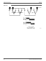
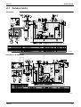
-07
ROOM SENSOR
P21
B
P1
FD15•20
P1
P2
P2
A
E
D
FD06~10
P1
P3
P6
C
A
P2
P6
P7
P3
P3
A
C
P10
P11
B
D
P6
C
P10
P11
B
P8
P10
P11
P12
P13
P14
P15
P16
P17
P18
DISPLAY
3
FD03~05
(P1257)
Remote Controller (Optional Accessories)
21
Optional accessories
Si42-107
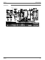
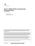
-079
A
A
D
B
B
J
C
ON
OFF COOL
D
E
HEAT
F
C
G
H
FD15•20
I
H
E-F
E-G
E-H
E-I
L
H
TEMPERATURE
22
(P1258)
Remote Controller (Optional Accessories)
Si42-107
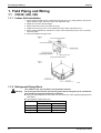
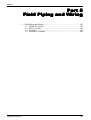
Part 5
Field Piping and Wiring
030 $
Field Piping and Wiring
/!-*4!*4!* /!$*4! *4!* 1
/*4!*-
'+54!!545 -1
'5!$*
'! *4'!* !
23
Field Piping and Wiring
Si42-107
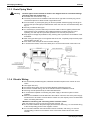
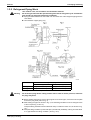
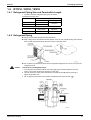
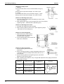
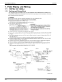
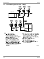
'"
',(-?(-?(-
""
660;
=6;)0.5064
06;666;
I66606
- 8=66)0$.
I604(=6
36(=0I(4
666;
6
$ 066
@
A'?;""5"B
,5$;;;
;
"3";
;""@""
! 06;;#66
=6#60066
6;
! 5(
0
'00#
@
/!-
/!
φ1K!4&S!
φ1K!4&S!
φ1K! 4&S+
φ1K! 4&S+
/!
φ1K!4&S!
φ1K! 4&S+
)0 G&H.
24
Field Piping and Wiring
Si42-107
Field Piping and Wiring
,;;":
;"?;!
;"5:
! '(6
;
660).;606(6
0).)0+.
! ;#0660 460
6
6)01!.6
(
6;;;;
=0
! 360EI6)
((
;.4(=066
0;60)01,.
Field Piping and Wiring
25
Field Piping and Wiring
Si42-107
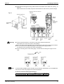
,@
4;5:"";!;5:"!<!5
:"@
! (;660
! :6
;6606:60
;
(
6606
! ;4=606;600
()6666:-?6.
0
! 6
! 606
66
(6(6
66
046(;
! *06;
06
(
;
! 06664
(6
6)0.
! 6(60
! 6((4
66
#"
! ((
;4(
(
(
! 5
! 0=46G30/0(H
66
! (
046(
E(
! 0(;(;6#
! ;=
;
066((;
! '6(
666#6
;
6646
6
;=?
640
A+;!
5
""
B
%6
6;
;(06
)0.
! ;66(40-
60
6
066(0
! ;6?(
40-56
0(;6
66
(
26
Field Piping and Wiring
Si42-107
Field Piping and Wiring
'6(
66(
).600(
6
! 6660660
6;(6
6;)0
-.6
4=6(66
6;
(0
%;6(;6
06(;
! /
006((
)&6
(
60.
! 36
06(004
6(
0606
06
((
;(
;
(;6
66600(
6
(
! 5""
5(
3
5&!3@ 9
#)((P.
!+
6
975"5!;;
5?;!;
55
! 6
6;
;
)0.6
;6(06
6
6;466
0666
Field Piping and Wiring
27
Field Piping and Wiring
Si42-107
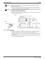
,"";!
;:$;";
"6;$
;8?
;<"
";
@
:"@
! 606
6;
! (6606
66()0.
4&
! 6
=(=6
6;
(
06
(646(
! :6(
6
=6
6
660
4
6066
)-
6(.
! 606I((46
(60
28
Field Piping and Wiring
Si42-107
Field Piping and Wiring
',(/-?(1-?(-
""
660;
=6;)0.5064
06;666;
I66606
- 8=66)0$.
' I604(=(6
' 36(=0I(4
666;
6
066
Field Piping and Wiring
29
Field Piping and Wiring
Si42-107
@
A'?;""5"B
,5$;;;
;
"3";
;""@""
! 06;;#66
=6#60066
6;
! 5(
0
'00#
/!$
@
φ1K!4&S!
φ1K! 4&S+
/! /!
φK4&S
φ- K4&S
φ+K!14&S
φ1K!14&S
)0 G&H.
! '(6
;
660).;606(6
0).)0+.
! ;#0660 460
6
6)01!.60
6;;
;;=0
0)
((
;.
30
@0
((60((/! C!
Field Piping and Wiring
Si42-107
Field Piping and Wiring
,@
4;5:"";!;5:"!<!5
:"@
! (;660
! :6
;6606:60
;
(
6606
! ;4=606;600
()666:-?6.
0
! 6
! 606
66
(6(6
66
0
! *06;
06
(
;
! 06664
(6
6)0.
! 6(60
! 6((4
66
#"
! ((
;4(
(
(
! 5
! 0=46G30/0(H
66
! (
046(
E(
! 0(;(;6#
! ;=
;
066((;
! '6(
666#6
;
6646
6
;=?
640
Field Piping and Wiring
31
Field Piping and Wiring
Si42-107
A+;!
5
""
B
%6
6;
;(06
)0.
! ;66(40-
60
6
066(0
! ;6?(
40-56
0(;6
66
(
'6(
66(
).600(
6
! 6660660
6;(6
6;)0
-.6
4=6(66
6;
(0
32
%;6(;6
06(;
! /
006((
)&6
(
60.
! 36
06(004
6(
0606
06
Field Piping and Wiring
Si42-107
Field Piping and Wiring
((
;(
;
(;6
66600(
6
(
! 5""
5(
3
#)((P.
5&!3@ 9
!+
6
975"5;
5?;!;
55
! 6
6;
;
)0.6
;6(06
6
6;466
0666
,"";!
;:$;";
"6;$
;8?
;<"
";
@
:"@
! 606
6;
! (6606
66()0.
4&
! 6
=(=6
6;
(
06
(646(
! :6(
6
=6
6
660
4
6066
)-
6(.
! 606I((46
(60
Field Piping and Wiring
33
Field Piping and Wiring
Si42-107
',-?(-
""
60)
((
;.
68
606;)0$.
5064
06;666;
- I66606
8=66)0+.
' I604(=(6
' 36(=0I(4
666;
6
066
!
;:$
'(6
6;
=
:6;
=6,46
,
34
36
606
6;6(J
',6
- '(6
66;46
6;
=6,66;
;
;;!
;:$;5?:;
"
!
6+218
;;""?"
""!
Field Piping and Wiring
Si42-107
Field Piping and Wiring
@
A'?;""5"B
,5$;;;
;
"3";
;""@""
! 06;;#66
=6#60066
6;
! 5(
0
'00#
/
@
)φK4&S.K
&9
)φ+K! 4&S .K
/!
)φ- K4&S.K
)φ1K!4&S .K
)01
G&H.
,;;":
;"?;!
;"5:
! 2606(60
4(6
60)0 .
! ;#06601460
6
6)0!.
(6066
6
($6460
!,
! 360TI6)
((
;.4(=066
0;60)0!,.
Field Piping and Wiring
35
Field Piping and Wiring
Si42-107
,@
4;5:"";!;5:"!<!5
:"@
! (;660
! :6
;6606:60
;
(
6606
! ;4=606;600
()666626.
0
! 6
! 606
66
(6(6
66
046(;
! *06;
06
(
;
! 06664
(6
6)0.
! 6(60
! 6((4
66
#"
! ((
;4(
(
(
! 5
! 0=46D3'<@/@'8D
66
! (
046(
T(
! 0(;(;6#
! ;=
;
066((;
! '6(
666#6
;
6646
6
;=?
640
A+;!
5
""
B
%6
6;
;(06
)0-.
! ;6(40
66
4
606
06
0600(
! ;6?(
4056
0(;6
66
(
'6(
66(
).600(
6
36
Field Piping and Wiring
Si42-107
Field Piping and Wiring
! 6660660
6;(6
6;)0-
.
6
4=6(66
6;(0
! 50(
6(;
=
366
;460
%;6(;6
06(;
! /
006((
)&6
(
60.
! 36
06(004
6(
0606
06
((
;(
;
(;6
66600(
6
(
! 5""
5(
Field Piping and Wiring
3
#)((P.
5&!3@ 9
!+
6
37
Field Piping and Wiring
Si42-107
975"5!;;
5?;!;
55
! 6
6;
;
)0.6
;6(06
6
6;46
60666
,"";!
;:$;<"
"
;
@
:"@
! 606
6;
! (6606
66()0$.
4&
! 6
=(=6
6;
(
06
(646(
! :6(
6
=6
6
660
4
6066
)-
6(.
! 606I((46
(60
38
Field Piping and Wiring
Si42-107
Field Piping and Wiring
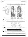
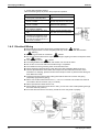
0'?(('?'
*5:";
(600#
).'00#
%
'00#
+
@
φ1K!
!!C
φ1K!
&9
φ1K!
);.(;006
:
8(;
006
8606
-!(
!(
! 0
;
6
! 06!(=6$((44;06=
=
((6
(
Field Piping and Wiring
! /;
666
0
6(6
0
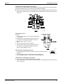
A;"3"<B
:6,
00
6((6
:6(6606
5
66
;6)(.60
0606
- /6
66
;66) ) .
39
Field Piping and Wiring
Si42-107
A&3"<B
%0
). :6(?
=40)U.
);. 6666:6
0
). :6(?
=40)U.
);. 6666:6
)"3"<<
:6
6
;6:=
(0
064;066
:0609J1$!,!<C
()!!,!=0C
(.
)"<
3=66
60666;
6=4066
:0609
J1 !,+!<C
()!!,!=0C
(.
8=66,
0
66
(6
(
:6
0(
66
;6
(
'"
60;6
(
36
06400(
6
6).
6-
;6
- 60;60609)
060
=6.
(064
0=
60
60
6
40
0#
:0609
(
)((.
φ1
-+!A-11!<C
(
)---A!+=0C
(.
!A
φ1
$ !A+!<C
(
)$-!A++!=0C
(.
$A1!
φ1
1+!A $!<C
(
)11!A!=0C
(.
1A--
(
Field Piping and Wiring
Si42-107
Field Piping and Wiring
%
060(40
((
;
! :69
6000
0606
6
:=60
600
'00,06
'0
60(
6000
). 60
600((:;
6060
);. 8=
6
(6;6
6(6
)06.
0
:;
600(VJ=0W
:6(((;06-!(
&06
)&.
(
!(
(
!(
(
-!(
600(
N
!-
!
!-
!!
!$-
'
6000
). 3660066(4
6060
66((6(46606
(46
600(6(6
(6
600(
Field Piping and Wiring
41
Field Piping and Wiring
Si42-107
- ((6
:=60(6(
006 06
60
6
6
(;6
(
- (
0;6
(
8=669,
0,
6
=66
(
0
'6(
N
6;#
69, ;,6
(
$ 600
6!=0?
(P@4
60
6;
6(
N
:66(0
#"
"
! 0(;
;9
30
! (;
606(
(
666(
30
! 206
! /
66044060
66
! 5
! :60;6(;!F
! /6(
660
(
! :6
600(
!!6(
! 36(0
04600(6
! 56
6(6
(6
6
(
(04666
(466064
6(6
(
! (606;4=0
66
660
)
606,0.
! <
66D&D4D&DD&-D(:6(;
6D<D()>(.
! <9#6
! 360664
0606
6=
=,6)φ-((.
! (66
(66
(;
42
Field Piping and Wiring
Si42-107
Field Piping and Wiring
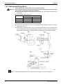
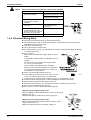
A)!
;!":!B
6060;46
86
0
(
8
'+5>
3)!.
"!FF,5@
'!!5>
'5>
"!FF,5@
"!FF,5@
'+5F
'!!5F
-!
-!
"!FF,5-@
"!FF,5-@
30
;6)!.
#
30#(
"!FF,5@!
(66
"!FF,5@!
;
"!FF,5@!
"!FF,5@!
"!FF,5@!
! 4
;=
/ 4&
! 269,0,6
6
(0066
4(=
6;
;(
! 4686
Field Piping and Wiring
43
Field Piping and Wiring
Si42-107
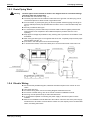
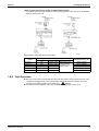
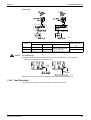
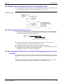
(/-
*%""!:";
*
%
'5!$*>
'5!$*:&
'0#
@
&9
φ1K!
φ1K!
! 56(;0306
)60(((
11 M.J%--$
%""!:"";
,
8((;0
06)6#0
906.
!(
8((;606
-!(
;
! /666
0(0600(
0600
! :6
06
4(==
=6;
06
)
.0φ$((
(P1454)
(P1453)
! 2
06)
.4;;660;
)6
=6
06.
(P1455)
44
Field Piping and Wiring
Si42-107
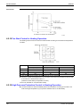
Field Piping and Wiring
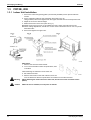
A
;"<"<B
:6(6
6066
;0:6
;6(
! :066;006
;6;
=6
06/06
;666
(P1456)
&<"<
:J
:6(?
=6
06(666(
(
66<6
)'0$.
:
J
:6(?
=
06(666(
(
66<6
)'0.
(P1457)
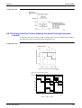
A
;"<"<
B
66
;6:=
(0
2066
06
:0609J1$!,!<C
()!!,!=0,
(.
(P1458)
A
;"<
B
56,,
6006
2066
:0609J1 !,+!<C
(
)!!,!=0,
(.
Field Piping and Wiring
45
Field Piping and Wiring
Si42-107
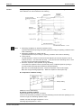
A
B
6
(00
66(
6
(I66066(9666
;00
66((=66
00
66(0;6
(
6606664
6
((0
606066
;
065
6
4
((;=6
(064
(46
;66
(;
=60
(
(P1459)
A
B
! 6:;6(
0
! 36
064
6;6600
(
606;6-;060(
! 2;69
6066
0
0?(6
! 6:;60609):(
6
06006.
(P1461)
:;
0#
:0609
(
0)((.
φ1
-+!A-11!<C
(
)---A!+=0C
(.
!A
φ1
1+!A $!<C
(
)11!A!=0C
(.
1A--
6
(P1460)
! 666600;
=6
(6
09
(6(4
4
;
600
! 4""
(P1462)
46
6660666
Field Piping and Wiring
Si42-107
Field Piping and Wiring
#<
:6
6
==;6(
:60;
6
==;6
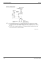
@
6
6
=
()<
(.
60<00
- =;04
6
06
/
60<0
6
=
(0
$ 6I
60606
+ &=(6<-+ ,+
(P1463)
;
:69
6000
06
06
6
:=60
600
%"
;
60
600((:;4-
60606
66
6).
0
:"%"
;5
(P1464)
(P1465)
A
B
! /=6060-(
5"
;;
3660066(4
6060
66((6(46606
(46
600((6(69
600;
6
600(
57!
:696,
6
6
(:=6
0(6(0,
Field Piping and Wiring
47
Field Piping and Wiring
Si42-107
<;7
;"!7!
;;
(
0;
6(
(6;6
690
6
=66
(
0
(
N
;#
- 69,
06(
;06
(
366,
6
N
46
=06(4
6
60
:6(
N
(P1466)
#"
"@
! 0(;(;6#
! (
6
6
(66
;
! 5
! 50!!Ω
! ;60+6
;(=
66)
606.
! >(
8=
;(
6
6469(
6066
;
)&4&4&-.
6
)6
6(0
66;
;669(4
6
(;(0;<
;6
.
! <9#;
;
! 36
;(644;
=
(P1467)
64
6
)@,
.
;66)φ-4φ+.)'0 .
! 6
00(6(
0=
! <;6
06
! *6666
6
! 2
! /6
((669(
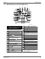
A!";B
'(
660
4
6(
66
A!";B
'6(
66
04
6(
66
(P1468)
48
Field Piping and Wiring
Si42-107
Field Piping and Wiring
5
(P1469)
8
3)!.
'5!$*>
"!FF,5@
'5!$*:&
"!FF,5@
#
30
;6
)!.
30#(
(
66
;
"!FF,5@!
"!FF,5@!
!%
4"!+'<,6
6.5""8
! 8=666
E(
6
60!!
(P1470)
! 0
60
(06
/ 4&
6
46(
Field Piping and Wiring
49
Field Piping and Wiring
/
Si42-107
(1-?(-
/ @
! :60(
60
'00J(
066066
#
#J0;
8
'00#
@
%/K:)8.
&9
%/K:)8.
/! *
7
'5! *
φK((
φ+K!1((
/!*
7
'5!*
φ- K((
8((
;
&06
!(
0
6
'
9
&06
8((
;
"06
/
+!(
-!(
φ1K!((
! 66;460
;
(664;(
6
I
00
! ! 95
! (66090
! 56
;60 !L;6609
50
Field Piping and Wiring
Si42-107
Field Piping and Wiring
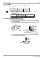
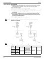
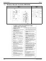
/ %;!;
4;5"
;!;;
%"!
;;!;'"!""
5;
5,
;;
5!;!;"
! (06(6
((
! :66;
6
==;6(
! '00(;
6
==;6
! @
60
6
=6
():66;
(.
606(600
- =;6I60
/
600
60
6
=6
(0
$ 6060
! 6(0
6006(;
)3606(06.
'5! *)>C:&.
'5!*)>C:&.
!=0)2
60.
$=0)2
60.
)360(6(06.
'5! *)>,:&.
:'0
()=0.
S
2
60
()=0.
7
60
()=0?(.
7
60
()=0?(.
!!
7)
:0
&06)(.
U(.
7)
:0
&06)(.
U(.
'5!*)>,:&.
:'0
()=0.
S
2
60
()=0.
!!$
! 6066(0
;
Field Piping and Wiring
51
Field Piping and Wiring
Si42-107
/ #"
@
! 0
(6
6;;
((
6
;6
06
66;0
! %
! '6G30/0(H660
! =(;(;
! :6
6(
0(6060
6(9
! :66(6
66;=6(
;
! 3
(;064;
/6066
(
?0
604
6
=?
! !";
! '686
4;!";5;<!
;!;:@;5
"
:""
"
"5;!"!!"";!:!;
!;
"55"69
"5;!8
8
52
'5! *>
-!
'5!*>
!
'5! *:&
!
'5!*:&
$!
3:
"!FF,5@
"!FF,5@
#
0
(6
6
;;
((
6
;
6
0
6
66;0
3025
3:
#
5&!
3@ 9
!+((P
6
Field Piping and Wiring
Si42-107
Field Piping and Wiring
! 660;460
;
(6406
6
6.5""8
8=66
E(
6
60
!!
! 0
60
(06
/ 4&
! %(
600660
(06
(
Field Piping and Wiring
/6686
53
Field Piping and Wiring
54
Si42-107
Field Piping and Wiring
Si42-107
Part 6
Function and Operation
% $
5$
%5 +
%6 %6)/,*7',5.
%6)/,*7'5,*.$!
- $
- 5$
- %5 $
Function and Operation
55
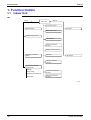
Function Outline
Si42-107
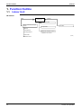
'
&"
',7-
(Input)
Indoor Unit
(Output)
Thermostat Control
Remote Controller with Liquid
Crystal
Fan Motor
Fan Operation
ON/OFF
Fan Operation
Cooling Operation
Malfunction Detection Function
∗ Fan Motor over Current
Thermostat
3 Minutes Timer
56
(P1259)
Funciton and Operation
Si42-107
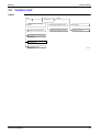
Function Outline
&
+"
(Output)
(Input)
Outdoor Unit
Discharge Pipe Thermostat
Switch
Compressor ON/OFF Control
Compressor
Fan Motor Thermostat Switch
Malfunction Detection Function
Outdoor Fan Motor
Compressor over Current Switch
RU Model Only
High Pressure Switch
RU Model Only
Low Pressure Switch
RU06K Only
Functon and Operation
(P1260)
57
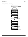
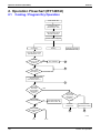
Operation Flow Chart
Si42-107
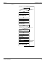
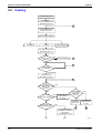
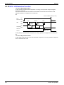
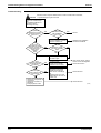
&'"!;
&'"!;6',7-C7'8
VW
Power switch on remote controller ON.
Is F1C
of indoor unit in
normal condition.
Unit does not
NO operate.
YES
Relay K1R of indoor unit is ON
Press Fan operation button.
Mgs K1M of indoor unit is ON.
Indoor unit Fan operates.
Press cooling button.
Thermostat
ON judgement.
Thermostat OFF
Thermostat ON
Mgs K1M of outdoor unit is ON,
then compressor and outdoor fans
operates.
One of safty device Q1L, Q2L and
S1B actuates.
Mgs K1M of outdoor unit is OFF.
Compressor and outdoor fans are
OFF. (Indoor fan keeps to operate.)
Safty device returns to normal.
Stop unit operation
and locate cause
of actuation of
safty device.
Manually resets the safty devices.
(P1261)
58
Funciton and Operation
Si42-107
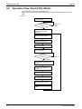
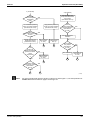
Operation Flow Chart
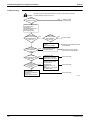
VW
Power switch on remote controller ON.
Is F1C
of indoor unit in
normal condition.
Unit does not
NO operate.
YES
Relay K1R of indoor unit is ON
Press Fan operation button.
Mgs K1M of indoor unit is ON.
Indoor unit Fan operates.
Press cooling button.
Thermostat
ON judgement.
Thermostat OFF
Thermostat ON
Mgs K1M of outdoor unit is ON,
then compressor and outdoor fans
operates.
F1C of indoor unit actuates.
Relay K1R is OFF and Mgs K1M
is OFF, then Mgs K1M of outdoor
unit is OFF also.
Indoor unit Fan stops, then
compressor and outdoor unit's fan
are OFF.
F1C of indoor unit returns to
normal.
Stop unit operation
and rocate cause
of actuation of
safty device.
Manually resets the F1C relay.
(P1262)
Functon and Operation
59
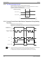
Operation Flow Chart
Si42-107
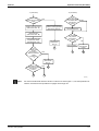
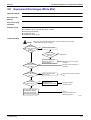
&'"!;6',7-C7-8
∗ :6/!$A!*7'5!$A!*
/*?/!*;6(
VW
Power switch ON.
Is safty
device in normal
condition.
Unit does not
NO operate.
YES
Relay K1R of outdoor unit is ON.
Relay K2R, K3R of indoor
unit are ON.
Press Fan operation button.
Mgs K2M of indoor unit is ON,
and relay K2R, K4R are ON.
Indoor Fan operates.
Press cooling button.
Thermostat
ON judgement.
Thermostat OFF
Thermostat ON
Mgs K1M of outdoor unit is ON,
then compressor and outdoor fans
operates.
One of the safty device Q1RP,
F1C, S1B, S1PH, Q1L, Q2L
acutuates.
Relay K1R of outdoor unit is OFF.
Relay K2R, K3R, of indoor unit is
OFF then K2M and K1M are OFF.
Fan and compressor are OFF.
Safty device returns to normal
condition.
(P1263)
60
Funciton and Operation
Si42-107
Operation Flow Chart
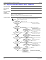
VW
Power switch ON.
Is safty
device in normal
condition.
Unit does not
NO operate.
YES
Relay K1R of outdoor unit is ON.
Relay K2R, K3R of indoor
unit are ON.
Press Fan operation button.
Mgs K2M of indoor unit is ON,
and relay K2R, K4R are ON.
Indoor Fan operates.
Press cooling button.
Thermostat
ON judgement.
Thermostat OFF
Thermostat ON
Mgs K1M of outdoor unit is ON,
then compressor and outdoor fans
operates.
F2C of indoor unit actuates.
Relay K2R, K3R, are OFF and
K2M and K1M are OFF also.
Fan and compressor are OFF.
F2C returns to normal condition.
(P1264)
Functon and Operation
61
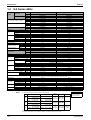
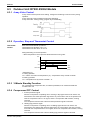
Electric Function Parts
Si42-107
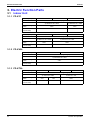
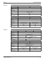
#"
'
',7-.
'(
!-
8
880
6
!
*'+,-4*'+,)/0:.
:%,*
-φ- !?F!=3
&*B:"!,$
!F
:%,*
-φ- !?F!+=3
&*B:"!,$
!F
8%
'
'(
8
880
6
8%
'
!
!$
!
!
*'+,-4*'+,)/0:.
:%
:%,*
-φ- !?F!+=3
-φ- !?F=3
&*,B:"!,$
!F
&*,B:!,$
!F
-$
',7-3%
'(
!-
!
*'+,-4*'+,)/0:.
8
%5
φ!?!F!=3
&*B:"!,
!F
880
6
8%
'
-
',7-4%
'(
8
880
6
8%
'
62
!
!$
!
*'+,-4*'+,)/0:.
:%
-φ!F!+=3
!
:%,*
-φ!F=3
&*,":"!,2
!F
&*,B:"!,$
!F
&*,B:!,$
!F
-
-
$!
Funciton and Operation
Si42-107
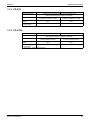
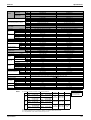
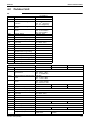
Electric Function Parts
',7-.
'(
8
880
6
8%
'
!
*'+,-):6(.4*'+,)/0:.
*'+,2):6(.7*:1∗
:%
:%
-φ- !?F!"#=3
-φ- !?F!"#-+=3
&*,B:!,$
!F
!
&*,B:!,$
!F
!
∗ *:1J-(0(
',7-4%
'(
8
880
6
!
*'+,-):6(.4*'+,)/0:.
*'+,2):6(.7*:1∗
:%
-φ!F$!"#=3
&*,B:!,$
!F
:%
-φ!F$!"#-+=3
"%,!,:'
!F
1
8%
'
∗ *:1J-(0(
Functon and Operation
63
Electric Function Parts
Si42-107
&
>'
8
(
*8
8
80
6
%5
)5.
8
%5
)&.
%5
8
:6(
R&
R&
'+5F&
"--R2
85!,
!3
85!/
!3
N
%J-XL
%<J $XL
'
'
8
8
2
:(
6
)/
60.
0'
,5:,-*
%J-XL?%<JXL
N
$$, +<
8
0
N
N
*
-'
'4
'
8
(
*8
80
6
8
%5
)5.
%5
)&.
8
R&
R&
'
64
'+5>
"--R/2
µ
N
'!!5>
'!!5F&
'5>
'5:&
"-$R/2
85!,
"-$R2
85!/
"-$R/2
85!,
"-$R/2
&
85!/
+3
1!3
+3
1!3
-3
3
$!3
!3
%5
8
:6(
8
'
2
8
:(
6
)/
60.
*
0'
-µ
!µ7 !µ
%J-XL
%<J $XL
µ
µ
,5:,-*
%J-XL?%<JXL
N
-'
8
N
$$,
+<
!µ
'4
'
0
N
$µ7 !µ
N
N
N
N
N
N
Funciton and Operation
Si42-107
Electric Function Parts
7-.
8
(
*8
80
6
8
%'
8)5.
8
8)&.
'5!$*>
'5! *>
'5!*>
B:!!2>
-6- !,F!"#
"%$,:'
!F
B:$/,>
-6- !,F+=3
B:--/,>
-6- !,F1=3
&*,!B:,
!F
,<%:
6!,!F$ 3
"%,-,:'
!F
3$ $!!
6!,!F$-!3
8
:6(
%J-XL
%<J!L
3$ !!
6!,!F$1!3
%J-XL
%<J $XL
'
'
8
8
$µ4!!F
$µ4!!F
µ4!!F
µ4!!F
R'
'6
:6(
6
)/
60.
2
"
6)"06
.
&
6)&
.
,<%:
6!,!F$$3
'B,!!F
5:,-*
%J-XL
%<JXL
2,/2 %J17!,!8
%<J$X!8
&2,B
%J,!!-X!!8
%<J!!X!!-8
!F
7-4%
8
(
*8
80
6
8
%'
8)5.
8
8)&.
'5! *:&
'5!*:&
B:1!2
-6!F$!"#
"%,-,:'
!F
B:-$/,
-φ!!F=3
"%,-,:'
!F
B:-!!/,
-6!!F+=3
&*,!B:,
!F
-
$
,<%:
6!,!F$!!3
3$ $!!
6!,!F$-!3
,<%:
6!,!F$!!3
8
:6(
%J-XL
%<J!L
3$ !!
6!,!F$1!3
%J-XL
%<J $XL
'
'
8
8
$µ4!!F
$µ4!!F
µ4!!F
µ4!!F
R'
'6
:6(
6
)/
60.
2
Functon and Operation
'5!$*:&
"
6)"06
.
&
6)&
.
'B,!F
5:,-*
%J-XL
%<JXL
2,/2 %J17!,!8
%<J$X!8
&2,B
%J,!!-X!!8
%<J!!X!!-8
!F
65
Electric Function Parts
66
Si42-107
Funciton and Operation
Si42-107
Part 7
Troubleshooting
8
$
% $
""'98
+!
6 +!
- :;6029(+
-
-
--
-
-$
-+
-
-1
Troubleshooting
:;6029( +
9(% +
%4;( +0%;(( +
9(6/4
;'36+
9(%;0 +$
9(/
60368 ++
9(
&<6=+
9(/
60/+1
67
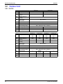
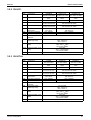
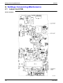
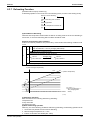
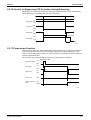
Maintenance Inspections
Si42-107
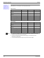
+
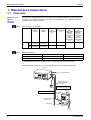
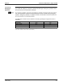
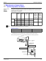
&<<!
D
&5"
&
:6060
;606
;6(
06;;'+,5
(6;
JG"H
0
"06
)8.
&
)8.
! $A1
"# )$A1.
$! +A
"# )+A!.
!-1A!1
)!A$!.
!-A!
)-A.
/
60
5
:(
J
:(
)L.
/
)L.
2
:(
/
60
:(
)L.
$!A1
!A
+!A
,A!
%5
J
/
2
:(
/
60
:(
)L.
A
+A
006=0?
(P
0%
"0%
5
%5
+L/2?1L32
L/2
-L/2
+L/2?$L32
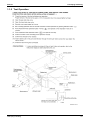
! /0(
466;
=
(
;6G
G
6
36(0(
46(60
Indoor unit
To dedicated breaker
Transmission wiring
between indoor and
outdoor units
What about switch capacity?
What about cable thickness?
What about voltage and current?
To dedicated
breaker
Refrigerant piping
(Liquid+gas)
Drain piping
Outdoor unit
Earth
(P1667)
68
Troubleshooting
Si42-107
"%7
E
&
F
Maintenance Inspections
366
((((#6;;)8
(,!((.
)36
0.
,
0
6
5?
%?%
%50
6
%5?
%
8'0
&
&
"06
&
'0
&
&
&
&
"06
"06
"06
"06
"06
"06
"06
"06
"06
38'0
/8'0
Y&
Y&
&
&
&
&
&
='0)@.
5
(
&
Y"06
&
&
&
&
Y360#6
;4;
6(
6((
Y/60
0604;
6(6(
(
- ;606;
(06
<
Troubleshooting
69
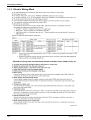
How to Handle Request for Maintenance
Si42-107
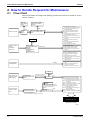
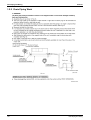
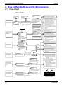
)!)"=+
'"!;
6
060
669
(6
(
Turn the power supply
switch ON or replace
the fuse.
Wait until
power failure
is over.
YES
YES
Doesn't run at all
Is there a
power
failure?
(1) The operation circuit fuse is
disconnected or is making poor contact.
(2) The operation swich is broken or its
contact is defective.
(3) The high pressure switch is broken.
(4) The fan motor's magnetic switch is
broken.
(5) The fan motor's protection thermostat is
being actuated or is broken.
(6) The compressor's overcurrent relay is
broken.
(7) The compressor's protective thermostat
is broken.
(8) The electrical system insulation is
defective.
(9) The compressor's magnetic switch's
contact is defective.
(10) The compressor is broken.
NO
The power supply switch is NO
OFF or the switch's fuse is
burnt.
Nomal
Runs
The fan comes on
but the
compressor
doesn't run.
Set the remote
controller's temperature
setting to:
(1)When
cooling:Minimum
(2)When
heating:Maximum
(11) Thermostat is broken.
(12) The cool/heat selector is broken.
(13) The operation switch is broken.
(14) The compressor's magnetic swich is
broken.
Doesn't run
(15) Over-charged with refrigerant.
(16) Air is mixed inside the refrigerant
circuit.
(17) The pressure switch is broken.
(18) The outdoor unit fan motor's magnetic
switch is broken.
(19) The outdoor unit fan motor's auxiliary
relay is broken.
Cooling
Cooling starts but
stops right away.
(20) The outdoor unit's heat exchanger is
dirty.
(21) There is something blocking the
outdoor unit's air flow.
(22) Malfunction of the outdoor unit's fan.
Nomal
The unit won't run
again for a while
after stopping.
Try turning the
Operation switch OFF
and On.
Did you allow 3 minutes to
elapse after turning ON?
YES
NO
Runs
Operation is
normal.
Is there something causing the
indoor load to be large, such as
an open window or door?
The unit runs but
doesn't cool the
room.
Measure the suction
/disharge temperature.
YES
Temperature
differential is 8~18˚C
NO
(23) Overcurrent relay (for compressor)
(24) Compressor's protective themostat
(25) The causes for the overcurrent relay
(for compressor) being actuated are:
(26)-1 Power supply voltage is lower than
prescribed.
(26)-2 High pressure is too high.
(26)-3 The power supply cord is too small.
(26)-4 The compressor is broken.
(27) The causes for the compressor's
protective thermostat
(27)-(1) Unsatisfactory compression from
the compressor
(27)-(2) Defective refrigerant
(27)-(3) Unsatisfactory refrigerant circulation
(Temperature differential
=suction temperature - discharge temperature)
OK.We'll be right over.
(Maintenance required)
(P1268)
70
Troubleshooting
Si42-107
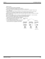
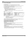
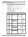
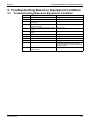
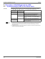
Troubleshooting Based on Equipment Condition
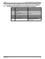
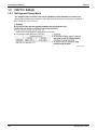
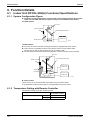
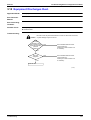
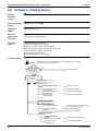
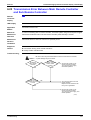
4:";9#=5
4:";9#=5
'(
0 +
-
4;
(
0;
((
9(64
; 0 +
6
9(; 0 +$
0
Troubleshooting
9(
9(
0 +0 +
$
+
9(
606(
0 ++
9(
6= 0 +
1
9(
60
9((
0 +1
'((
0
(6
6066
(;
71
Troubleshooting Based on Equipment Condition
Si42-107
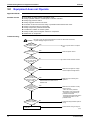
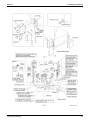
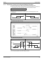
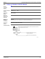
#=5&
%"
:"+"
/,*
:"
!
!
!
!
!
!
!
!
!
!
;
6
(
606
6
(0
6(
6((
(
(
6(
(
(0
6
(
8
(
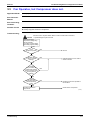
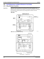
4:";
Caution
Be sure to turn off power switch before connect or disconnect connector,
or parts damage may be occurred.
Is power
switch OFF or fuse
for control circuit
blown?
YES
Turn on power switch or replace
fuse.
NO
Is there
power outage?
YES
Wait until power returns.
NO
Is the
power supply
between terminal C-D
(or 3) from remote
controller?
NO
Check remote controller contact
YES
Is the
power supply
on MgS "K1M or K2M"
coil of indoor
fan motor?
YES
Malfunction of MgS coil or MgS
contact replace the MgS switch.
NO
Is the
power supply
to Relay "K1R" coil of
indoor or outdoor
unit? ∗Note
NO
Is there
any malfunction
or actuation of safty
devices?
YES
∗ K1R relay rocated on indoor unit for
FD03·04·05K and outdoor unit for
FD06·08·10K
YES
NO
Is the
sufficient insulation
in electric system?
YES
Possibly faulty electric wiring
or relay etc.
72
NO
Malfunction of K1R relay and
replace it.
Malfunction or actuation of safty
device such as:
· indoor fan motor protection
thermostat or over current relay
· Compressor overload relay or
protection thermostat
· Discharge pipe thermostat switch
· High pressure switch or Low
pressure switch
Check the faulty insulation parts or
wiring.
Check electric wiring or relay etc.
(P1269)
Troubleshooting
Si42-107
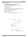
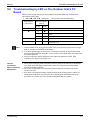
Troubleshooting Based on Equipment Condition
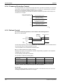
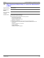
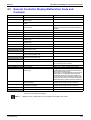
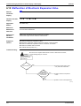
'&?:5
%"
:"+"
/,*
:"
! (
! (0
6
(
4:";
Caution
Be sure to turn off power switch before connect or disconnect connector,
or parts damage may be occurred.
Make the following
temperature setting using
remote controller.
Cooling: Lowest setting
YES
Does
equipment operate?
YES
Normal.
NO
Is the
power supply
between terminal B-D
(or 3) from remote
controller?
NO
Malfunction of remote controller
contact or thermostat
YES
Is the power
supply on MgS coil for
compressor.
YES
Malfunction of MgS coil or MgS
contact.
Replace the MgS switch.
NO
Is there
any malfunction or
actuation of safty
devices?
NO
Possibly faulty electric
wiring or relay etc.
YES
Malfunction or actuation of safty
device such as:
· Discharge pipe thermostat
· Thermostat switch for outdoor
fan motor.
(In case of R71~125FU)
Check electric wiring between
indoor and outdoor unit or relay
etc.
(P1270)
Troubleshooting
73
Troubleshooting Based on Equipment Condition
Si42-107
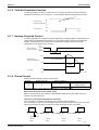
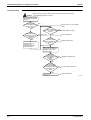
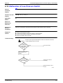
"&:55"
%"
:"+"
/,*
:"
!
!
!
!
!
!
!
!
600
0(
6
(0
6(
(
6
60
:60(
8
4:";
Caution
Be sure to turn off power switch before connect or disconnect connector,
or parts damage may be occurred.
[ Outdoor unit [
Does the
fan rotate?
NO
YES
Does the fan
overheated?
YES
Malfunction of fan
motor
Check the magnetic
switch and aux. switch
for fan motor
Replace fan motor.
NO
Is there any
item disturbing
airflow?
YES
Remove the disturbing
item
NO
Is the heat
exchanger soiled?
YES
Cleaning of the heat
exchanger
NO
Possible causes as
follows:
* Refrigerant overcharge
* Mixing of air in
refrigerant system
* Faulty pressure switch
After vacuum drying,
charge correct amount
of refrigerant
Check the pressure
switch
(S1271)
74
Troubleshooting
Si42-107
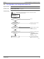
Troubleshooting Based on Equipment Condition
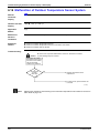
%#=5;,!?
:
;"
%"
:"+"
/,*
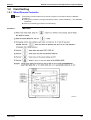
:"
! %
)
(.
! (
6(
! %
(
60
&0
606
;
8
(
! (
6((
60
(
(
0
0
4:";
Caution
Be sure to turn off power switch before connect or disconnect connector,
or parts damage may be occurred.
Turn the operation switch
ON and OFF, then wait at
ON side.
Does the unit
start operation after
3 minutes?
YES
[Electric system]
Power
supply voltage is
NO
within ±10 % of specified
voltage.
NO
Is the
discharge side of
compressor hot after
unit operation
stop?
YES
Check on the cause why
overcurrent relay (for
compressor) or
compressor protection
thermostat acted.
NO
Not so hot
YES
Is the size
of power cable
through total length
correct?
[Refrigerant circuit]
Normal. Unit is in 3-min standby
mode
Contact power company
Check compressor
NO
Replace power cable
YES
After vacuum drying,
charge correct amount of
refrigerant. Then, start
operation again.
Is
there any
temperature
difference between inlet
and outlet of
capillary
tube?
YES
Malfunction of
compressor
NO
Capillary tube clogged.
Check compressor
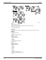
(P1272)
Troubleshooting
75
Troubleshooting Based on Equipment Condition
/
Si42-107
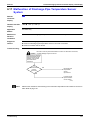
#=5&:<"
%"
:"+"
/,*
:"
! %
)
(.
! (
6(
! %
(
60
&0
606
;
8
(
! (
6((
60
(
(
0
0
4:";
Caution
Be sure to turn off power switch before connect or disconnect connector,
or parts damage may be occurred.
Measure the temperature of
suction air and discharge
air.
Temperature difference =
Suction air temp. –
Discharge air temp.
Temperature
difference for cooling
should be between
8 and 18 ˚C.
YES
YES
Normal.
NO
Possible causes as follows
* Incorrect selection of model
* Affection of direct sun
NO
Does
any frost
generate around
inlet port of indoor unit
heat exchanger or
outlet port of
capillary
tube?
Does the
heat load increase
after installation
of the unit?
YES
Is the
operation current
less than specified
level?
Additional unit installation
should be considered
YES
NO
NO
Gas shortage possibly
generates trouble.
Does indoor
unit discharge flow
rate down?
YES
NO
Is the
level of high
pressure higher than
normal level?
NO
Possible causes as follows
* Insufficient compression of
compressor
* Insufficient circulation of
refrigerant
* Faulty expansion valve
76
YES
* Clogged air filter
* Soiled heat exchanger
* Malfunction of fan motor
Possible causes as follows
* Refrigerant overcharge
* Soiled heat exchanger
* Short circuit of discharge
air
* Disturbing item in air flow
* Malfunction of fan motor of
outdoor unit
After vacuum drying, charge
correct amount of refrigerant.
Check each section
Check each item
Check each item
(P1273)
Troubleshooting
Si42-107
0
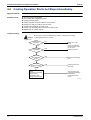
Troubleshooting Based on Equipment Condition
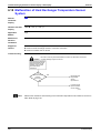
#=5,
;;+
%"
:"+"
/,*
:"
!
!
!
!
!
"(
6(
6
60
00
8
(
4:";
Caution
Be sure to turn off power switch before connect or disconnect connector,
or parts damage may be occurred.
Is the
room temperature
higher than set value in
cooling
operation?
YES
NO
Continue unit operation.
Is white fog
coming out from
the unit?
NO
Normal
YES
It may be necessary to
remove the source of
humid condition.
Is the heat
exchanger of indoor
unit soiled?
YES
Remove the source of humid
condition.
Cleaning of heat exchanger is
necessary.
NO
Is the site
dusty or with dense
oil mist?
YES
Dust or oil mists should
be removed.
Remove the source of oil mist or
dust.
NO
Is the airflow
rate too small?
YES
Possible causes as follows
* Clogged air filter
* Malfunction of fan motor
Cleaning of air filter
Check fan motor
(P1274)
Troubleshooting
77
Troubleshooting Based on Equipment Condition
1
Si42-107
#=5
;@
%"
:"+"
/,*
:"
! 600
! 0(
! 60060)6.
4:";
Caution
Be sure to turn off power switch before connect or disconnect connector,
or parts damage may be occurred.
Does the
noise generate with
vibration of whole
ceilings and
walls?
[Installation work side]
YES
Correction of installation
Reinforcement for ceilings or
NO
Does the
noise generate
with vibration of
unit mounting
section?
YES
Continuous
YES
slight noise of "shoo....."
during cooling
operation
NO
Is the
piping secured?
NO
YES
NO
Does the
pipe contact with
casing?
NO
Sound
of "shoo..."
generates just after
operation start
or stop.
[Power supply side] YES
Does the fan
contact with other
parts?
Insert shock absorber in
mounting section, or strengthen
the mounting section.
YES
Insert cushion materials to the
pipe support such as saddle.
YES
NO
Sound
of "shoo..." generates
during cooling or after
operation
stop.
NO
Normal. The sound is flushing
noise of gas (refrigerant) inside
air conditioning unit
Normal. The noise is a sound
generated at the time of gas
Disassemble and remove parts
contact.
YES
Normal. Operation sound of
draining device
Correct piping manually or attach
a dead weight to pipe
NO
Is
the noise
flushing sound from
pressure reducing
valve or capillary
tube?
NO
78
YES
Normal.
* Excess charge of
refrigerant
* Air intrudes into
refrigerant system
* Flushing noise due to
refrigerant shortage.
(Sound of shoo...)
After vacuum drying, charge
correct amount of refrigerant.
(P1275)
Troubleshooting
Si42-107
G
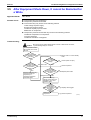
Troubleshooting Based on Equipment Condition
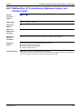
#=5,
;,
%"
:"+"
/,*
:"
! (
! (T6
4:";
Caution
Be sure to turn off power switch before connect or disconnect connector,
or parts damage may be occurred.
Does
the trouble
generate at the
time of operation start
again after extended
period of
operation?
YES
Dust collected inside the indoor
unit are blown out.
Cleaning for inside of indoor unit
is necessary.
NO
Is air filter
equipped?
NO
YES
Dust collected inside the indoor
unit are blown out.
Cleaning for inside of indoor unit
is necessary.
Install air filter.
(P1276)
Troubleshooting
79
Troubleshooting Based on Equipment Condition
80
Si42-107
Troubleshooting
Si42-107
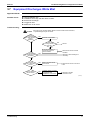
Part 8
Removal Procedure
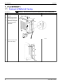
'+5> Removal Procedure
'(0
'(%58 '(
2 '((
81
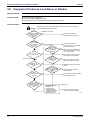
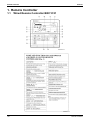
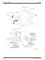
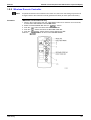
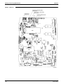
For R71FUY1
Si42-107
'0'.
5<"#$"
-
82
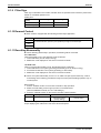
9""!":5:"!@
'(61
'(6
60
'(6-
6
0
(;60
'(6 6
0
Removal Procedure
Si42-107
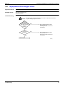
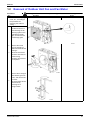
For R71FUY1
5<"&''+
9""!":5:"!@
! '(60
4
4
0
6
(06
0
'(6
6 ;06
6006
?;(?
064(6
600
-
'(6
;0
0
/
6(
(6
;E0
(
6
'(660
;06
(4(6
(
:6(;
;
(;
(06-
60;
Removal Procedure
83
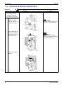
For R71FUY1
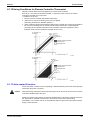
5<"#"
"9$
-
84
9""!":5:"!@
! '(64
0
0
06
(0
'(6
(
6
60)
(04
6
.
Si42-107
'(6
;
6606
;
6
(;6
04
4(6
(
(06
04(6
6
;
'(6
;
Removal Procedure
Si42-107
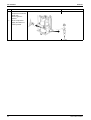
For R71FUY1
5<"5
9""!":5:"!@
! '(6
04
4
0
(
'(6
(
0
/
6
(
(6
(
(
-
"6;#
6
60
4
((60
6
4
Removal Procedure
85
For R71FUY1
86
Si42-107
'(6
(E6
;
5:,;
&6
(
06
Removal Procedure
Si42-107
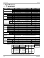
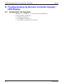
Part 9
Appendix
0/0(
0%
30/0( 1!
!"# 1!
$!"# 1+
Appendix
87
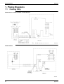
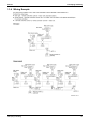
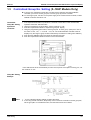
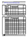
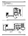
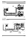
Piping Diagrams
Si42-107
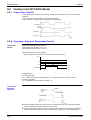
,5
"&"
',(-C0'F',(-C(('F',(-C'
',(/-C(/-
88
Appendix
Si42-107
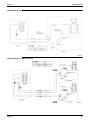
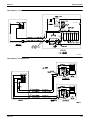
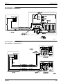
Piping Diagrams
',(1-C(1-F',(-C(-
',-C(1-2F',(-C(-2
Appendix
89
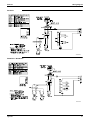
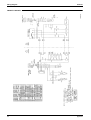
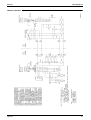
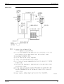
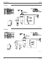
Wiring Diagram
Si42-107
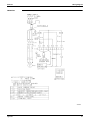
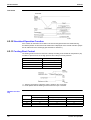
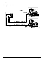
,5
()*
',(H(H(-.
90
Appendix
Si42-107
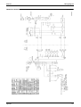
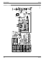
Wiring Diagram
0'.
3D000995C
(('.F'.
3D001007C
Appendix
91
Wiring Diagram
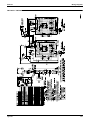
Si42-107
',(/-.C(/-.
92
Appendix
Si42-107
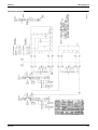
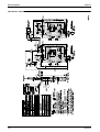
Wiring Diagram
',(1-.C(1-.F',(-.C(-.
Appendix
93
Wiring Diagram
Si42-107
',-.C(1-.2F',(-.C(-.2
94
Appendix
Si42-107
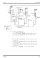
Wiring Diagram
',(>(-.
Appendix
95
Wiring Diagram
Si42-107
',H(-.
96
Appendix
Si42-107
Wiring Diagram
/()*
',(H(-3%
Appendix
97
Wiring Diagram
Si42-107
0'3%
3D005375C
(('3%
3D005376C
98
Appendix
Si42-107
Wiring Diagram
',(-4%
Appendix
99
Wiring Diagram
Si42-107
'4%
100
Appendix
Si42-107
Wiring Diagram
',(/-4%C(/-4%
Appendix
101
Wiring Diagram
Si42-107
',(1-4%C(1-4%F',(-4%C(-4%
102
Appendix
Si42-107
Wiring Diagram
',-4%C(1-4%2F',(-4%C(-4%2
Appendix
103
Wiring Diagram
Si42-107
',(?(-3%F',(>(-4%
104
Appendix
Si42-107
Wiring Diagram
',H(-4%
Appendix
105
Wiring Diagram
Si42-107
106
Appendix
Si42-107
Packaged Air Conditioners
Duct Connection Type
(High static Pressure
Application)
FDY-K(A) Series
— Heat Pump —
Model Series
Class
Indoor Units
Outdoor Units
6HP
8HP
10HP
15HP
20HP
FDY06K(A) FDY08K(A) FDY10K(A) FDY15K(A) FDY20K(A)
RY140KU
RY200KU
RY250KU
RY200KU×2 RY250KU×2
107
Si42-107
108
Si42-107
Part 1
Model Name and
Power Supply
8<(
!
"06
:!
Model Name and Power Supply
109
Model Series and Nomenclature
Si42-107
+"5
"
);
4
+"!"
5:"
!"#
!"
>
-φ4- !AF4!"#
)8-.
)%5.
:&
-φ4!F4$!"#
$!"#
>&
-φ4- !F4$!"#
)8-.
)%5.
&
/>!$*).>
'>!*5>
/>! *).>
'>!!*5>
/>!*).>
'>!*5>
/>*).>
'>!!*5>K
/>!*).>
'>!*5>K
/>! *).:&
'>!!*5:&
/>!*).:&
'>!*5:&
/>*).:&
'>!!*5:&K
/>!*).:&
'>!*5:&K
/>! *).>&
'>!!*5>&
/>!*).>&
'>!*5>&
/>*).>&
'>!!*5>&K
/>!*).>&
'>!*5>&K
=J8%5
5
"
FDY
06
K
Y1
Duct Connection High Static Pressure Type
FDY : Heat Pump
Capacity Index
Major Design Category
Power Supply Symbol
Y1 : 3φ 380~415V 50Hz
TAL : 3φ 220V 60Hz
YAL : 3φ 380V 60Hz
(P1015)
&
RY
140
KU
Y1
Outdoor Units
Capacity Index
Major Design Category
Power Supply Symbol
Y1 : 3φ 380~415V 50Hz
TAL : 3φ 220V 60Hz
YAL : 3φ 380V 60Hz
110
(P1016)
Model Name and Power Supply
Si42-107
External Appearance
#$"%
#$"%
/>!$*).
/>! *).
/>*).
/>!*).
/>!*).
5""
3:
2'2$
3:
2'$
3:
2'$
0'
05
):.
&
'>!*5
Model Name and Power Supply
'>!!*5
'>!*5
111
External Appearance
112
Si42-107
Model Name and Power Supply
Si42-107
Part 2
Functions
Functions
113
Functions
Si42-107
'
'
%8
/
"06
:
/>,*
"
<
&/3'(
"
"
"
:(
(
?"60%
"
"
60%
/0
"
"
8
60
-!(
(
/>!$*
/>! A!*
60&06
,
(
6
60
2
=:(
=
;'(
/>!$4! 4!*%
"
"
"
"J
114
Functions
Si42-107
Part 3
Specifications
$
Specifications
*!"# $
*$!"# *!"# !
*$!"# 115
Specifications
Si42-107
+"
-()*
',.(/-.
',.(1-.
',.(-.
.(-.
.((-.
.(-.
??
14!!? 4!!? 4!!
4!!?4!!?4!!
-?-?4!!?4!!?4!!
-4!!?-4!!?-4!!
??
+$4 !!?+4+!!?+4+!!
14-!!?14!!?14!!
-?-?-
+ 4 !!?+14!!?+ 4 !!
141!!?!4!!!?141!!
+$?+?+
14!!?14!!?14!!
-4+!!?-4-!!?-4-!!
1?1?1
!!4-!!?!!4+!!?!!4-!!
4-!!?4!!?4-!!
',.(/-.
',.(1-.
',.(-.
&
!4!0
).?).?)-.
!4!-"0
).?).?)-.
=3
2?6
=
?6
=3
2?6
=
?6
/(
"K3K/
:
'K0K
6
:
/
8%
'
&
8
6306
&9
0
@
/
3
'(
3
((
(P
=3
(Q?(
2).
=0
((
((
!K4-!K !)362. !!K4-!K !)362. !!K4--!K !)362.
)3&",O:;.
KK!
-KK!
-KK!
!1
!!!
2/
2/
2/
!+
$
!
!
1
!
φ1)2#0.
φ+)2#0.
φ1)2#0.
φ1)2#0.
φ)2#0.
φ $)2#0.
:-?):6.
:-?):6.
:-?):6.
2')
.
2')
.
2')
.
N
N
N
&
.(-.
/(
"K3K/
:
'K0K
6
8
(
:
8%
8
:
8%
'
8
6306
&9
0
@
/
((
(P
=3
3
(Q?(
=0
((
((
((
/
'0
&06
'0
8&06
8"06/
8
'0
60
8
'%
60
/0<
M
(
(
(
=0
&
.((-.
.(-.
4-K !K-+!
4!K4 !K$1!
4!K4 !K$1!
)3&",O:;.
K$!K!
K!K!
K!K!
!
+
1+
B:+!2,>
B:-$/,>
B:--/,>
"(
:
1!
B8
"8
"8
1!7 !
-!71!
-!71!
!
!
+
!
!$
φ1).
φ+).
φ1).
φ1).
φ)0.
φ $)0.
φ$!)".
N
N
:6(
:6(
(("06
6
("06
6&
&
6'6
6'6
%
)
((.
%
)
((.
!!U!
!!U!
!!U!
F)
:.
:;
!)906+!(.
!)906+!(.
!)906+!(.
-!
-!
-!
'
'
'
-1)60-!(.
!)60(.
)60(.
5<%@//U*
5<%@//U*
5<%@//U*
$
-!
-!
/!1 -!
/!- ! <(
;60
0
J
).
).
)-.
+L) L./24
1L)$+L.32
"0
J
L)+!L./2
%J -L)1L./24
L)+L.32
%J +L)L./24
$L)-L.32
J
J
+L) L./24
1!L)$$L.32
!L)$ L./2
%J -L)1L./24
L)+L.32
%J +L)L./24
$L)-L.32
J
J
+L) L./24
1!L)$$L.32
%J -L)1L./24
L)+L.32
L)+!L./2
%J +L)L./24
$L)-L.32
(
0
&06
"#,F
(
)"#.
!"#,- !F
N
(
)"#.
!"#,- !F
N
+(
)"#.
!"#,F
$
=
?6S=3K $!
2?6S=3K-
(S(Q?(K--
! 0
04
0
0(6
!- "0
4
060(6
040=).)'>!*5>.
116
Specifications
Si42-107
+"
Specifications
&
!4!0
).?).?)-.
!4!-"0
).?).?)-.
=3
2?6
=
?6
=3
2?6
=
?6
',.-.
',.(-.
.((-.2
.(-.2
!?-?-
!4!!!? 4!!!? 4!!!
-+4 !!?-+4!!?-+4!!
$? ?$
4!!!?-4!!!?4!!!
- 4!!?- 4!!?- 4!!
-1?-!?-!
4!!!? 4!!!? 4!!!
$4!!?4$!!?4$!!
$$?$ ?$$
1-4!!!?14!!!?1-4!!!
4+!!? 4 !!? 4+!!
',.-.
',.(-.
/(
"K3K/
:
'K0K
6
:
/
8%
'
&
8
6306
&9
0
@
/
3
'(
3
((
$K4$!K !
$K41 !K !
)3&",O:;.
-K$K!
-K$K!
!+ !11!
2/
2/
-+
-$
$$
+
+
$!
$
+
φ+)2#0.
φ1)2#0.
φ)2#0.
φ $)2#0.
:):6.
:):6.
2'
2'
N
N
(P
=3
(Q?(
2).
=0
((
((
&
.((-.2
/(!
"K3K/
:
!
'K0K
6
8
(!
:
8%
8
:
!
8%
'
8
6306!
&9
0
!
@
/
((
(P
=3
3
(Q?(
=0
((
((
((
/
'0
&06
'0
8&06
8"06/
8
'0
60
8
'%
60
/0<
M
(
(
(
=0
&
.(-.2
4!K4 !K$1!
4!K4 !K$1!
)3&",O:;.
K!K!
K!K!
+
1+
B:-$/,>
B:--/,>
"(
:
1!
"8
"8
-!71!
-!71!
!
+
!
!$
φ+).
φ1).
φ)0.
φ $)0.
N
N
:6(
(("06
6&
6'6
%
)
((.
!!U!U!
!!U!U!
:;
!)906+!(.
!)906+!(.
-!
-!
'
'
!)60(.K5
)60(.K5
5<%@//U*
5<%@//U*
-!K5
-!K5
/!1 !
! <(
;60
0
J
).
).
)-.
+L) L./24
1L)$+L.32
"0
J
L)+!L./2
%J -L)1L./24
L)+L.32
%J +L)L./24
$L)-L.32
J
J
+L) L./24
1!L)$$L.32
!L)$ L./2
%J -L)1L./24
L)+L.32
%J +L)L./24
$L)-L.32
J
J
+L) L./24
1!L)$$L.32
%J -L)1L./24
L)+L.32
L)+!L./2
%J +L)L./24
$L)-L.32
(
0
&06
"#,F
(
)"#.
!"#,- !F
N
(
)"#.
!"#,- !F
N
+(
)"#.
!"#,F
$
=
?6S=3K $!
2?6S=3K-
(S(Q?(K--
! 0
04
0
0(6
!- "0
4
060(6
! :6
66
Specifications
117
Specifications
Si42-107
-/()*
+"
!4!-"0
).?).?)-.
.((-4%
.(-4%
.((-.%
.(-.%
=3
2?6
=
?6
=3
2?6
=
?6
??
+$4 !!?+4+!!?+4+!!
14-!!?14!!?14!!
-?-?-
+ 4 !!?+14!!?+ 4 !!
141!!?!4!!!?141!!
+$?+?+
14!!?14!!?14!!
-4+!!?-4-!!?-4-!!
1?1?1
!!4-!!?!!4+!!?!!4-!!
4-!!?4!!?4-!!
/(
',.(1-4%
',.(-4%
',.(1-.%
',.(-.%
=3
(Q?(
2).
=0
((
((
4%
.((-4%
.(-4%
.%
.((-.%
.(-.%
((
:
'K0K
6
(P
:&
>&
8
(
=3
3
(Q?(
=0
((
((
((
/
'0
&06
'0
8&06
8"06/
8
'0
60
8
'%
60
/0<
!!K4-!K !)362.
!!K4--!K !)362.
)3&",O:;.
-KK!
-KK!
!!!
2/
2/
$
1
!
φ+)2#0.
φ1)2#0.
φ)2#0.
φ $)2#0.
:-?):6.
:-?):6.
2')
.
2')
.
N
N
(P
"K3K/
:
8%
8
:
8%
'
8
6306
&9
0
@
/
4%
.%
((
&
/(
',.(-4%
',.(-.%
4%
"K3K/
:
'K0K
6
:
/
8%
'
&
8
6306
&9
0
@
/
3
'(
3
',.(1-4%
',.(1-.%
.%
&
!4!0
).?).?)-.
4%
.%
M
(
(
(
=0
&
4!K4 !K$1!
4!K4 !K$1!
)3&",O:;.
K!K!
K!K!
+
1+
B:/,
B:-!!/,
B:/,>"
B:-!!/,>"
"(
:
+
"8
"8
-!71!
-!71!
$!
1!
+1
!
φ+).
φ1).
φ)0.
φ $)0.
N
N
:6(
(("06
6&
6
'6
%
)
((.
!!U!
!!U!
:;
!)906+!(.
!)906+!(.
-!
-!
'
'
!)60(.
)60(.
5<%@//U*
5<%@//U*
-!
-!
/!1 -
! <(
;60
0
J
).
).
)-.
+L) L./24
1L)$+L.32
"0
J
L)+!L./2
%J -L)1L./24
L)+L.32
%J +L)L./24
$L)-L.32
J
J
+L) L./24
1!L)$$L.32
!L)$ L./2
%J -L)1L./24
L)+L.32
%J +L)L./24
$L)-L.32
J
J
1L) L./24
1!L)$$L.32
%J $L)L./24
L)+L.32
L)+!L./2
%J +L)L./24
$L)-L.32
(
0
&06
"#,F
(
)"#.
$!"#,!F
$!"#,- !F
N
(
)"#.
$!"#,!F
$!"#,- !F
N
+(
)"#.
$!"#,!F
$!"#,- !F
- ?
- $
=
?6S=3K $!
2?6S=3K-
(S(Q?(K--
! 0
04
0
0(6
!- "0
4
060(6
118
Specifications
Si42-107
Specifications
+"
!4!-"0
).?).?)-.
.((-4%2
.(-4%2
.((-.%2
.(-.%2
=3
2?6
=
?6
=3
2?6
=
?6
!?-?- +
!4!!!? 4!!!?-4!!!
-+4 !!?-+4!!?--4-!!
$? ?$
4!!!?-4!!!?4!!!
- 4!!?- 4!!?- 4!!
-1?-!?+ 4!!!? 4!!!?$4!!!
$4!!?4$!!?!4+!!
$$?$ ?$$
1-4!!!?14!!!?1-4!!!
4+!!? 4 !!? 4+!!
/(
4%
',.-4%
',.(-4%
.%
',.-.%
',.(-.%
((
=3
(Q?(
2).
=0
((
((
/(!
"K3K/
:
!
'K0K
6
4%
.((-4%2
.(-4%2
.%
.((-.%2
.(-.%2
((
(P
:&
>&
8
(!
=3
3
(Q?(
=0
((
((
((
/
'0
&06
'0
8&06
8"06/
8
'0
60
8
'%
60
/0<
$K4$!K !
$K41 !K !
)3&",O:;.
-K$K!
-K$K!
!+ !11!
2/
2/
-+
-$
$$
+
+
$!
$
+
φ+)2#0.
φ1)2#0.
φ)2#0.
φ $)2#0.
:):6.
:):6.
2'
2'
N
N
(P
&
:
8%
8
:
!
8%
'
8
6306!
&9
0
!
@
/
',.(-4%
',.(-.%
4%
"K3K/
:
'K0K
6
:
/
8%
'
&
8
6306
&9
0
@
/
3
'(
3
',.-4%
',.-.%
.%
&
!4!0
).?).?)-.
4%
.%
M
(
(
(
=0
&
4!K4 !K$1!
4!K4 !K$1!
)3&",O:;.
K!K!
K!K!
+
1+
B:/,
B:-!!/,
B:/,>"
B:-!!/,>"
"(
:
+
"8
"8
-!71!
-!71!
$!
1!
+1
!
φ+).
φ1).
φ)0.
φ $)0.
N
N
:6(
(("06
6&
6
'6
%
)
((.
!!U!U!
!!U!U!
:;
!)906+!(.
!)906+!(.
-!
-!
'
'
!)60(.K5
)60(.K5
5<%@//U*
5<%@//U*
-!K5
-!K5
/!1 (
! <(
;60
0
J
).
).
)-.
+L) L./24
1L)$+L.32
"0
J
L)+!L./2
%J -L)1L./24
L)+L.32
%J +L)L./24
$L)-L.32
J
J
+L) L./24
1!L)$$L.32
!L)$ L./2
%J -L)1L./24
L)+L.32
%J +L)L./24
$L)-L.32
J
J
1L) L./24
1!L)$$L.32
%J $L)L./24
L)+L.32
L)+!L./2
%J +L)L./24
$L)-L.32
0
&06
"#,F
(
)"#.
$!"#,!F
$!"#,- !F
N
(
)"#.
$!"#,!F
$!"#,- !F
N
+(
)"#.
$!"#,!F
$!"#,- !F
- ?
- $
=
?6S=3K $!
2?6S=3K-
(S(Q?(K--
! 0
04
0
0(6
!- "0
4
060(6
! :6
66
Specifications
119
Specifications
+"
Si42-107
-%()*
',.(/-%.
',.(1-%.
&
.(-.
.((-.
.(-.
??
14!!? 4!!? 4!!
4!!?4!!?4!!
-?-?4!!?4!!?4!!
-4!!?-4!!?-4!!
??
+$4 !!?+4+!!?+4+!!
14-!!?14!!?14!!
-?-?-
+ 4 !!?+14!!?+ 4 !!
141!!?!4!!!?141!!
+$?+?+
14!!?14!!?14!!
-4+!!?-4-!!?-4-!!
1?1?1
!!4-!!?!!4+!!?!!4-!!
4-!!?4!!?4-!!
',.(/-%.
',.(1-%.
',.(-%.
!4!0
).?).?)-.
!4!-"0
).?).?)-.
=3
2?6
=
?6
=3
2?6
=
?6
/(
"K3K/
:
'K0K
6
:
/
8%
'!
&!
8
6306
&9
0
@
/
3
'(
)%.
3
((
(P
=3
(Q?(
2).
=0
((
((
!K4-!K !)362. !!K4-!K !)362. !!K4--!K !)362.
)3&",O:;.
KK!
-KK!
-KK!
!1
!!!
2/
2/
2/
!+
,
$ ,$
-, !
,
,
-,!
1
!
φ1)2#0.
φ+)2#0.
φ1)2#0.
φ1)2#0.
φ)2#0.
φ $)2#0.
:-?):6.
:-?):6.
:-?):6.
2'$
2'$
2'$
2'$
2'$
2'$
&
.(-.
/(
"K3K/
:
'K0K
6
8
(
:
8%
8
:
8%
')?".!
8
6306
&9
0
@
/
((
(P
=3
3
(Q?(
=0
((
((
((
/
'0
&06
'0
8&06
8"06/
8
'0
60
8
'%
60
/0<
M
(
(
(
=0
&
.((-.
.(-.
4-K !K-+!
4!K4 !K$1!
4!K4 !K$1!
)3&",O:;.
K$!K!
K!K!
K!K!
!
+
1+
B:+!2,>
B:-$/,>
B:--/,>
"(
:
1!
B8
"8
"8
1!7 !
-!71!
-!71!
!?1,!-?1!?- ,?
+?$,+1,$
!
!$
φ1).
φ+).
φ1).
φ1).
φ)0.
φ $)0.
φ$!)".
N
N
:6(
:6(
(("06
6
("06
6&
&
6'6
6'6
%
)
((.
%
)
((.
!!U!
!!U!
!!U!
F)
:.
:;
!)906+!(.
!)906+!(.
!)906+!(.
-!
-!
-!
'
'
'
-1)60-!(.
!)60(.
)60(.
5<%@//U*
5<%@//U*
5<%@//U*
$
-!
-!
/!- -
/!- -$
! <(
;60
0
J
).
).
)-.
!
!-
!
120
',.(-%.
+L) L./24
1L)$+L.32
"0
J
L)+!L./2
%J -L)1L./24
L)+L.32
%J +L)L./24
$L)-L.32
J
J
+L) L./24
1!L)$$L.32
!L)$ L./2
%J -L)1L./24
L)+L.32
%J +L)L./24
$L)-L.32
J
J
+L) L./24
1!L)$$L.32
%J -L)1L./24
L)+L.32
L)+!L./2
%J +L)L./24
$L)-L.32
(
0
&06
"#,F
(
)"#.
!"#,- !F
N
(
)"#.
!"#,- !F
N
+(
)"#.
!"#,F
$
=
?6S=3K $!
2?6S=3K-
(S(Q?(K--
0
04
0
0(6
"0
4
060(6
040=).)'>!*5>.
')'.6- !F,F
Specifications
Si42-107
+"
Specifications
&
!4!0
).?).?)-.
!4!-"0
).?).?)-.
=3
2?6
=
?6
=3
2?6
=
?6
',.-%.
',.(-%.
.((-.2
.(-.2
!?-?-
!4!!!? 4!!!? 4!!!
-+4 !!?-+4!!?-+4!!
$? ?$
4!!!?-4!!!?4!!!
- 4!!?- 4!!?- 4!!
-1?-!?-!
4!!!? 4!!!? 4!!!
$4!!?4$!!?4$!!
$$?$ ?$$
1-4!!!?14!!!?1-4!!!
4+!!? 4 !!? 4+!!
',.-%.
',.(-%.
/(
"K3K/
:
'K0K
6
:
/
8%
'!
&!
8
6306
&9
0
@
/
3
'(
)%.
3
((
$K4$!K !)362.
$K41 !K !)362.
)3&",O:;.
-K$K!
-K$K!
!+ !11!
2/
2/
-+
-$,-$
$$,$$
+
+
,
$!,$!
$
+
φ+)2#0.
φ1)2#0.
φ)2#0.
φ $)2#0.
:):6.
:):6.
2'$
2'$
2'$
2'$
(P
=3
(Q?(
2).
=0
((
((
&
.((-.2
/(!
"K3K/
:
!
'K0K
6
8
(!
:
8%
8
:
!
8%
')?".!
8
6306!
&9
0
!
@
/
((
(P
=3
3
(Q?(
=0
((
((
((
/
'0
&06
'0
8&06
8"06/
8
'0
60
8
'%
60
/0<
M
(
(
(
=0
&
! <(
;60
0
J
).
).
)-.
!
!-
!
!
Specifications
.(-.2
4!K4 !K$1!
4!K4 !K$1!
)3&",O:;.
K!K!
K!K!
+
1+
B:-$/,>
B:--/,>
"(
:
1!
"8
"8
-!71!
-!71!
!?- ,?
+?$,+1?$
!
!$
φ+).
φ1).
φ)0.
φ $)0.
N
N
:6(
(("06
6&
6'6
%
)
((.
!!U!U!
!!U!U!
:;
!)906+!(.
!)906+!(.
-!
-!
'
'
!)60(.K5
)60(.K5
5<%@//U*
5<%@//U*
-!K5
-!K5
/!- -
+L) L./24
1L)$+L.32
"0
J
L)+!L./2
%J -L)1L./24
L)+L.32
%J +L)L./24
$L)-L.32
J
J
+L) L./24
1!L)$$L.32
!L)$ L./2
%J -L)1L./24
L)+L.32
%J +L)L./24
$L)-L.32
J
J
+L) L./24
1!L)$$L.32
%J -L)1L./24
L)+L.32
L)+!L./2
%J +L)L./24
$L)-L.32
(
0
&06
"#,F
(
)"#.
!"#,- !F
N
(
)"#.
!"#,- !F
N
+(
)"#.
!"#,F
$
=
?6S=3K $!
2?6S=3K-
(S(Q?(K--
0
04
0
0(6
"0
4
060(6
:6
66
')'.6- !F,F
121
Specifications
Si42-107
-%/()*
+"
!4!-"0
).?).?)-.
.((-4%
.(-4%
.((-.%
.(-.%
=3
2?6
=
?6
=3
2?6
=
?6
??1
+$4 !!?+4+!!?$+4$!!
14-!!?14!!?+4!!!
-?-?1
+ 4 !!?+14!!?+ 4!!
141!!?!4!!!?14+!!
+$?+?14!!?14!!? 41!!
-4+!!?-4-!!?!41!!
1?1?1
!!4-!!?!!4+!!?114-!!
4-!!?4!!?4!!!
/(
',.(1-%4%
',.(-%4%
',.(1-%.%
',.(-%.%
=3
(Q?(
2).
=0
((
((
4%
.((-4%
.(-4%
.%
.((-.%
.(-.%
((
:
'K0K
6
(P
:&
>&
8
(
=3
3
(Q?(
=0
((
((
((
/
'0
&06
'0
8&06
8"06/
8
'0
60
8
'%
60
/0<
!!K4-!K !)362.
!!K4--!K !)362.
)3&",O:;.
-KK!
-KK!
!!!
2/
2/
$
1
!
φ+)2#0.
φ1)2#0.
φ)2#0.
φ $)2#0.
:-?):6.
:-?):6.
2'$
2'$
2'$
2'$
(P
"K3K/
:
8%
8
:
8%
')?".
8
6306
&9
0
@
/
4%
.%
((
&
/(
',.(-%4%
',.(-%.%
4%
"K3K/
:
'K0K
6
:
/
8%
'
&
8
6306
&9
0
@
/
3
'(
)%.
3
',.(1-%4%
',.(1-%.%
.%
&
!4!0
).?).?)-.
4%
.%
M
(
(
(
=0
&
4!K4 !K$1!
4!K4 !K$1!
)3&",O:;.
K!K!
K!K!
+
1+
B:/,
B:-!!/,
B:/,>"
B:-!!/,>"
"(
:
+
"8
"8
-!71!
-!71!
$!?+
1!?+
+1
!
φ+).
φ1).
φ)0.
φ $)0.
N
N
:6(
(("06
6&
6
'6
%
)
((.
!!U!
!!U!
:;
!)906+!(.
!)906+!(.
-!
-!
'
'
!)60(.
)60(.
5<%@//U*
5<%@//U*
-!
-!
/!- -+
(
! <(
;60
0
J
).
).
)-.
+L) L./24
1L)$+L.32
"0
J
L)+!L./2
%J -L)1L./24
L)+L.32
%J +L)L./24
$L)-L.32
J
J
+L) L./24
1!L)$$L.32
!L)$ L./2
%J -L)1L./24
L)+L.32
%J +L)L./24
$L)-L.32
J
J
1L) L./24
1!L)$$L.32
%J $L)L./24
L)+L.32
L)+!L./2
%J +L)L./24
$L)-L.32
0
&06
"#,F
(
)"#.
$!"#,!F
$!"#,- !F
N
(
)"#.
$!"#,!F
$!"#,- !F
N
+(
)"#.
$!"#,!F
$!"#,- !F
- ?
- $
=
?6S=3K $!
2?6S=3K-
(S(Q?(K--
! 0
04
0
0(6
!- "0
4
060(6
122
Specifications
Si42-107
Specifications
+"
!4!-"0
).?).?)-.
.((-4%2
.(-4%2
.((-.%2
.(-.%2
=3
2?6
=
?6
=3
2?6
=
?6
!?-?- +
!4!!!? 4!!!?-4!!!
-+4 !!?-+4!!?--4-!!
$? ?$
4!!!?-4!!!?4!!!
- 4!!?- 4!!?- 4!!
-1?-!?+ 4!!!? 4!!!?$4!!!
$4!!?4$!!?!4+!!
$$?$ ?$$
1-4!!!?14!!!?1-4!!!
4+!!? 4 !!? 4+!!
/(
4%
',.-%4%
',.(-%4%
.%
',.-%.%
',.(-%.%
((
=3
(Q?(
2).
=0
((
((
/(!
"K3K/
:
!
'K0K
6
4%
.((-4%2
.(-4%2
.%
.((-.%2
.(-.%2
((
(P
:&
>&
8
(!
=3
3
(Q?(
=0
((
((
((
/
'0
&06
'0
8&06
8"06/
8
'0
60
8
'%
60
/0<
$K4$!K !)362.
$K41 !K !)362.
)3&",O:;.
-K$K!
-K$K!
!+ !11!
2/
2/
-+
-$
$$
+
+
$!
$
+
φ+)2#0.
φ1)2#0.
φ)2#0.
φ $)2#0.
:):6.
:):6.
2'$
2'$
2'$
2'$
(P
&
:
8%
8
:
!
8%
')?".
8
6306!
&9
0
!
@
/
',.(-%4%
',.(-%.%
4%
"K3K/
:
'K0K
6
:
/
8%
'
&
8
6306
&9
0
@
/
3
'(
)%.
3
',.-%4%
',.-%.%
.%
&
!4!0
).?).?)-.
4%
.%
M
(
(
(
=0
&
4!K4 !K$1!
4!K4 !K$1!
)3&",O:;.
K!K!
K!K!
+
1+
B:/,
B:-!!/,
B:/,>"
B:-!!/,>"
"(
:
+
"8
"8
-!71!
-!71!
$!?+
1!?+
+1
!
φ+).
φ1).
φ)0.
φ $)0.
N
N
:6(
(("06
6&
6
'6
%
)
((.
!!U!U!
!!U!U!
:;
!)906+!(.
!)906+!(.
-!
-!
'
'
!)60(.K5
)60(.K5
5<%@//U*
5<%@//U*
-!K5
-!K5
/!- -1
(
! <(
;60
0
J
).
).
)-.
+L) L./24
1L)$+L.32
"0
J
L)+!L./2
%J -L)1L./24
L)+L.32
%J +L)L./24
$L)-L.32
J
J
+L) L./24
1!L)$$L.32
!L)$ L./2
%J -L)1L./24
L)+L.32
%J +L)L./24
$L)-L.32
J
J
1L) L./24
1!L)$$L.32
%J $L)L./24
L)+L.32
L)+!L./2
%J +L)L./24
$L)-L.32
0
&06
"#,F
(
)"#.
$!"#,!F
$!"#,- !F
N
(
)"#.
$!"#,!F
$!"#,- !F
N
+(
)"#.
$!"#,!F
$!"#,- !F
- ?
- $
=
?6S=3K $!
2?6S=3K-
(S(Q?(K--
! 0
04
0
0(6
!- "0
4
060(6
! :6
66
Specifications
123
Specifications
124
Si42-107
Specifications
Si42-107
Part 4
Remote Controller
'( $
3'(2'$
3'(2'$+
- 3'(2'$ Remote Controller
125
Remote Controller
Si42-107
5""
126
5""9
Remote Controller
Si42-107
Remote Controller
5""9/
5
4
7
6
10
2
1
3
A
8
9
11
hr
hr
NOT
AVAILABLE
TEST
18
12
13
TEST
14
Fig.1
17
15
16
3PN02535-8L-0
NAME AND FUNCTION OF EACH
SWITCH AND DISPLAY ON THE
REMOTE CONTROLLER
The illustrations in this operating manual correspond to the remote control format BRC1C type.
1
2
3
ON/OFF BUTTON
Press the button and the system will start. Press
the button again and the system will stop.
OPERATION LAMP (RED)
The lamp lights up during operation.
DISPLAY “
” (UNDER CENTRALIZED CONTROL)
When this display shows, the system is
UNDER CENTRALIZED CONTROL.
(This is not a standard specification.)
DISPLAY “ ” “
”“
” (VENTILATION/AIR CLEANING)
This display shows that the total heat
exchange and the air cleaning unit are in
operation (These are optional accessories).
A
4
5
DISPLAY “ ” “ ” “ ” “ ”
(OPERATION MODE)
This display shows the current OPERATION MODE.
6
DISPLAY “
TEST” (INSPECTION/TEST
OPERATION)
When the INSPECTION/TEST OPERATION BUTTON
is pressed, the display shows the system mode is in.
DISPLAY “
7
hr
hr
” (PROGRAMMED TIME)
This display shows the PROGRAMMED TIME
of the system start or stop.
8
DISPLAY “
” (SET TEMPERATURE)
This display shows the set temperature.
9
DISPLAY “
” (TIME TO CLEAN AIR FILTER)
Not applied on this model.
10
C
DISPLAY “
” (DEFROST)
NOT
DISPLAY “ AVAILABLE
”
If
indoor
unit
does
not have a function, this
11
display is indicated when pressing buttons for
the function.
12
13
TIMER MODE START/STOP BUTTON
TIMER ON/OFF BUTTON
INSPECTION/TEST OPERATION BUTTON
14 This button is used only by qualified service
persons for maintenance purposes.
PROGRAMMING TIME BUTTON
15 Use this button for programming “START and/
or STOP” time.
TEMPERATURE SETTING BUTTON
16
Use this button for SETTING TEMPERATURE.
FILTER SIGN RESET BUTTON
17
Not applied on this model.
OPERATION MODE SELECTOR BUTTON
18
Press this button to select OPERATION MODE.
NOTE
For the sake of explanation, all indications are
shown on the display in Figure 1 contrary to
actual running situations.
3PN02535-8L-3
Remote Controller
127
Remote Controller
Si42-107
"5""9/
'
128
'
Remote Controller
Si42-107
Part 5
Field Piping and Wiring
030 -!
Field Piping and Wiring
/>!$4! 4!*). -!
/>?!*). '>!*5 $
'>!!*5?'>!*5 129
Field Piping and Wiring
Si42-107
'"
',.(/?(1?(-6%8
@
130
Field Piping and Wiring
Si42-107
Field Piping and Wiring
,@
Field Piping and Wiring
131
Field Piping and Wiring
Si42-107
#"
@
132
Field Piping and Wiring
Si42-107
Field Piping and Wiring
Field Piping and Wiring
133
Field Piping and Wiring
134
Si42-107
Field Piping and Wiring
Si42-107
Field Piping and Wiring
#$5"
Field Piping and Wiring
135
Field Piping and Wiring
136
Si42-107
Field Piping and Wiring
Si42-107
Field Piping and Wiring
4&
Field Piping and Wiring
137
Field Piping and Wiring
Si42-107
',.F(-6%8
@
138
Field Piping and Wiring
Si42-107
Field Piping and Wiring
Field Piping and Wiring
139
Field Piping and Wiring
Si42-107
,@
140
Field Piping and Wiring
Si42-107
Field Piping and Wiring
#"
@
Field Piping and Wiring
141
Field Piping and Wiring
142
Si42-107
Field Piping and Wiring
Si42-107
Field Piping and Wiring
Field Piping and Wiring
143
Field Piping and Wiring
Si42-107
#$5"
144
Field Piping and Wiring
Si42-107
Field Piping and Wiring
4&
Field Piping and Wiring
145
Field Piping and Wiring
Si42-107
.(-
+$55%""!:";<",
'>!*5
8;0&06
8;&/
!()9&06+!(.
-!(
%";
! .(-
146
Field Piping and Wiring
Si42-107
Field Piping and Wiring
57,!&
:696,
6
6
(:=60
(6(0,
<6,
6,
66
666(
(6;6690
:=
66
;
6((
66(0,;6;
6
(
(
-(
;#
669
)'0-.
N
06(;0
6
(
366,
6
46
=06(4
66
0
N
:66(0
(046(
6G5H6%<;6(
46066(
((
G5H
0
(
6(4(366(
G5H46
();(-!(.:6(
60
! 666600;
=6
(6
09
(6(4
4;
600
! 4""
Indoor unit
Oil trap
Gas piping
H15m
Liquid piping
H Marks. Install trap at
each difference in
height 15m
Outdoor unit
(P1021)
Field Piping and Wiring
6660666
147
Field Piping and Wiring
Si42-107
.((-F.(-
+$55%""!:";,
&:%<%<@8:'&
! 560(
66#(
;0
''@'<:<@3%'*'%/5'
! 2(0=6606(((;064
(((;06(((;
66
;60;
:"<@%'85&:<%5%':%<>:8
! 5;
60=)
.;
600360
6460
)46(
6;
60=.
! 6;
66#)8((
J!0.
! &06;
66;6;)(((06J!
(.
!- :=066;
669
)8((;06
J!(.
! 506;(6(
0
! 0();6=6
.6=4;6(6
;46906)&.6
1PN04787-1A-1
060
%5
'>!!C!:)>4:&4>&.'!!C!:)>4:&4>&.
:
:?::
/;::
8((; &≥(
06
8((; &≤()+!(.
06):6
906.
&78)&4&4&-.≥(
&78)&4&.78)&-4&4&4&$.
≥(
&78)&4&4&-.≤!( &78)&4&.78)&-4&4&4&$.
)+!(.
≤!()+!(.
8((;
06;
6
8((;
06
;
6
)<
&≤&4
&-≤&4&≤&$.
8)&4&4&-.≤!(
8)&4&.78)&-4&4&4&$.≤!(
&U&2≤!(
&U&/≤!(
&S8)&4&.
&2S8)&4&.
&S8)&4&4&-.
&/S8)&4&4&-.
)&7&$.U)&7&-.≤!()<.
8((; "≤-!(
8)"4"4"-.≤-!(
&S8)&4&.
&2S8)&4&.
&U&2≤!(
&S8)&-4&.
&S8)&-4&.
&U&≤!(
&@S8)&4&$.
&"S8)&4&$.
&@U&"≤!(
8)"4"4"-4".≤-!(
8((;
;
6
"U"2≤!(
8)"4"4"-.S"
8)"4"4"-.S"2
"U"/≤!(
8)"4"4"-4".S"
8)"4"4"-4".S"/
1PN04787-1A-2
148
Field Piping and Wiring
Si42-107
Field Piping and Wiring
%";
&*@,::4F558/">/':%<
60
(4
6
=6(
060
)'
60606;.
6
6
=
()<
(.
60<00
- =;04
6
06
/
60<0
6
=
(0
$ I
60)
600(.60(9
+ %6
//:%<&"'@<@8%5<:%''@'<:
! 3606
(4
6060(6;
6
600(6;
=6;
=6
6;
:6;
0)'6;.
! 604
606
0(69
)'6060.
! #0
600(
%
')>.!!)>4:&4>&.
')>.!)>4:&4>&.
006
)(.
'0#
@ &9
'0#
@ &9
:
&
&
φK((
φK((
φ+K!1((
φ+K!1((
φ $K((
φ $K((
φ1K!((
φ1K!((
:
&4&
&
φ1K!((
φK((
φ1K! ((
φ+K!1((
φ1K!((
N
φ1K! ((
N
&A&/;: &
φ1K!((
φK((
φ1K! ((
φ+K!1((
N
φ $K((
N
φ1K!((
&4&
&-A&$
φ1K!((
φ1K!((
φ1K! ((
φ$K! ((
φ1K!((
φ1K!((
φ1K! ((
φ$K! ((
).'>)"(.
&9
%,06)&.
60()=0.
# (
!(
(
!(
(
-!(
-(
!(
(
!(
)((.
φ+
φ1
N
N
!!
!+!
!!
!
!
!
!!
!
!
-!
-!!
!
-!
1!
!!
$!
!
$-!
&9
%,06)&.
#
60()=0.
)((.
(
!(
(
!(
φ$
φ1
Field Piping and Wiring
!
!
!-!
!!
!
!+
!$!
!!
149
Field Piping and Wiring
Si42-107
1PN04788-1
AB
/;:
66
600(6;
6
&Z&J6φ1
&-A&$J6φ$
A#$5"B
"
60
600(6;)
'>!*5.
%,06
J&S$(
:6
600(
S-=0
4!F4"
%,06
J&S$(
J&S(
J&S(
:6
600(
S-7!+7!+
S!=0
,:"4!
%,06
J&S$(
J&S(
J&S(
J&-S$(
J&S(
J&S-(
J&$S(
:6
600(
S-7!+7!+7!-!7!7!7!
S+=0
150
Field Piping and Wiring
Si42-107
Part 6
Field Setting
86
)'8
?'.
0 - #@<0)A!"8%. +
0
08
52 - /
64B(2 $
- '
:;$
- (0
% $
-- 8
80$
Field Setting
151
Method of Field Set (Reset after Maintenance Inspection/Repair)
Si42-107
+;'"
6+
F8
#$"
(6(
(4(
?4
06;
0
(
):60((
60
(6'6
(.
152
Field Setting
Si42-107
Method of Field Set (Reset after Maintenance Inspection/Repair)
'"
5""
Field Setting
)0(;((6(
66
.
! 0
;(;
6006G8(;H4G':%/<%H4G%</
%/<%H
! '60
0
A99/B
153
Method of Field Set (Reset after Maintenance Inspection/Repair)
Si42-107
A9/B'',.7-%5""
154
Field Setting
Si42-107
Method of Field Set (Reset after Maintenance Inspection/Repair)
"5""
Field Setting
(6460(6;
60'6
()6;=.
6
A9/B'',.7-%5""
366((466G
H;(((
4
6&/:8%/
68%/<%66G
H;
- 66G
H;
6':%/<%
66G
H;
6%</%/<%
66G
H;60:
66G
H;6<%'8&8%/
155
Method of Field Set (Reset after Maintenance Inspection/Repair)
Si42-107
'"
156
Field Setting
Si42-107
Method of Field Set (Reset after Maintenance Inspection/Repair)
"*D6>()+"&"8
! 0
#
6
(
%<?%
4660<
60;(
! :60<466
(
4
%<?%
"*
D
:5
""
6
?;6
(66((4
6G(H
506(
;46(<G!!H
- 66
?;
60<
5060((0(;460<
60)@<
6,!!4,!4,4,!!,4
:6%<?%
6
600(;
;6
60
6.
66(%<?%;6
0<
$ 66
?;6((
∗66;
6
(
04
4
6(<G-!H
D
#$5"
Field Setting
G4H
*>'
0(
4(
(
60<4
60<
#
46
6
157
Settings Concerning Maintenance
Si42-107
+
9
',.(/>(-6%83#
158
Field Setting
Si42-107
Settings Concerning Maintenance
.(-.
Field Setting
159
Settings Concerning Maintenance
Si42-107
.((H(-.
160
Field Setting
Si42-107
Existence of DIP Switch, Jumper and BS
#$
,!
;?I59
4:"
8
2
:
/
6
/
F
%
/0
/
'>!*5>
'>!!C
!*5>
11
!!$
B(
/
8'@<>
%%&?
%<?
%
":
"
2
/-
"
"
"
"
:6(
60
"
"
"
(
/?
/
"
"
<
/
62/)!*5(.
V"58W
EMERGENCY
ON
COOL
FORCED
DEF / PUMP
DOWN
ON
BS1
OFF
HEAT
OFF
2
1
2
ON
1
DEF START
CONDITION
EV OPEN
DURING DEF
Note 3
DS3
DS1
(P1292)
/
62/)')>.!!C!*5(.
V":58W
DEFROST
STARTING
TEMP.
ON
FORCED SERVICE
DEF ·
PUMP
MONITOR
DOWN
HAP
H1P
H2P
BS1
OFF
Field Setting
BS1
DS1
NORMAL
COOL
HEAT
SS1
EMERGENCY
[GRN]
[RED]
[RED]
(P1293)
<
2;)(?
0.
062;
;6
6
0(
:
(,)00.462
;
;69(6
0(466;
(;#6(;#0(4
69
646
6
6
4
60
:
60660462;:6
6
)
0.
366
(469((
66
<-J'1G:(
0G(
161
Existence of DIP Switch, Jumper and BS
Si42-107
#5
&
#5
&
>
6((;
600606(0
6).
6E;(G<(HG(0
H36
666
9(
0(:6;;
;(
(0((0
8
/'0
/>A*
"
N
! 86
60((0
#5
&
&
/((
0(0
%6
666%
J
.(-5"K
:66(0
6G%HG"H60
GH
0%;(66;
=
V":58W
DS3 SETTING
ON
COOL
ON
COOL
ON
OFF
HEAT
OFF
COOL
COOL
or
HEAT
OFF
HEAT
FACTORY SET
FORCED
COOLING
HEAT
FORCED
HEATING
(S1295)
J
.((H(-5"K
:66(0
6G"H60GH
0%;(66;
=
V":58W
<FORCED COOLING>
NORMAL
HEAT
COOL
EMERGENCY
NORMAL
HEAT
NORMAL
HEAT
COOL
<FACTORY SET>
COOL
EMERGENCY
EMERGENCY
<FORCED HEATING>
(P1296)
162
Field Setting
Si42-107
Existence of DIP Switch, Jumper and BS
#5
&
6;
0(0
4
%
0-(40(0
;
6;
(0
4;(0
;66
/(69((6(
0(0
(0
(,
46
;
6(
(0
:6;;
(069((
(0
0
"0
(
,3>F&F
%<
%
%<
%<
%5
5
%<
%<
%<
%<
/0(0
6040
-(6),
%.
Field Setting
163
Existence of DIP Switch, Jumper and BS
Si42-107
+
+
6(
66
?;(((
6(
(
606(4
66
?
;(((
- 6(<
6(<66?(0;
6<
6<66((:':?:%;
6
0
6()84.
6;;
$ 60
)8.
;606(%<?%;
+ '6((
:6
?;(
4:"
8
<
!
%86 ('(/
8
"
>
6066
660((0(,
;
/ 66
/
60((0(,
;
/
01
02"
60
-
%<
:6%<
6
0
6
600
0(06
G
IH
GIH;
5<
60
60<
6<
600
660((0(,
;
%;(
);;
6
6((
.
164
Field Setting
Si42-107
Part 7
Function and Operation
% $$
5$$
%5 $+
%
6)'>!*5. $
0?0(/% $
"0 +!
- %
6)'>!!4!*5. +
- 0?0(/% +
- "0 +
+$
5+$
%5 +1
:6(:('
:; :6(:('
:; $ / $ 5/>!$A!*).
$ %5'>!*58 $- %5'>!!C!*58 1+
Function and Operation
165
Function Outline
Si42-107
'
&"
',.
(Input)
Indoor Unit
(Output)
Thermostat Control
Suction Sensor
Fan Motor
Monitoring Function
Heat Exchange Sensor
Fan Operation
Freeze-up Protection
Function
Heating Overload Control
Emergency Operation
Switch
Defrosting
LED Display
Cold Air Prevention
Function
Remote Controller with
Liquid Crystal
ON/OFF
Timer Setting
Operation Mode Guard
Function
Operation Mode Sellection
Thermostat
Malfunction Detection
Function
(P1302)
166
Function and Operation
Si42-107
Function Outline
&
.7-
(Input)
Outdoor Unit
(Output)
Compressor ON/OFF
Control
Outdoor Temperature
Sensor
3-minute Standby Function
Compressor
Heat Exchange
Temperature Sensor
Defrosting
4-way Valve
Discharge Pipe
Temperature Sensor
Forced Defrosting
Fan Motor
PS for High Pressure
Protection
4-way Valve Control
LED Display
PS for Low Pressure
Control
Outdoor Unit Fan Control
Overload Relay
Overload Control
Fan Motor Temperature
Switch
Indoor Unit Signal
∗1
Setting Switch & Jumper
Wire
Malfunction Detection
Function
Simulated Operation
Function
(P1303)
'G
/
64B(2H$)∗.
Function and Operation
167
Operation Flowchart (RY140KU)
Si42-107
&'"!
;6.(-8
"F5,&
Power Switch ON
Initializing of Electronic
Expansion Valve
(See Section 6. 2. 4.)
Start Operation Using
Remote Controller.
Operation Mode Judgment
Heating
Cooling/Dry
Emergency Operation
(See Section 6. 2. 9.)
Four-Way Valve Control
(See Section 6. 2. 1.)
Is safety
device in normal
condition?
NO
Error Indication
A
YES
B
Thermostat
ON Judgment
Thermostat OFF
Thermostat ON
Startup Control
(See Section 6. 2. 11.)
C
Is
discharge
thermistor
disconnected?
(See Section
6. 2. 7.)
YES
Is
cumulative
retry total 6?
(See Section
6. 2. 5.)
NO
Is thermistor
in normalcondition?
NO
Simulated Operation
(See Section 6. 2. 10.)
YES
Is discharge
pipe temperature
high?
NO
YES
Shutdown
Due to Error
Thermostat OFF
(See Section 6. 2. 2.)
A
B
YES
NO
(P1304)
To ∗1
168
To ∗2
Function and Operation
Si42-107
Operation Flowchart (RY140KU)
*1 (Continued)
Is outside
heat exchanger
temperature
high?
*2 (Continued)
Discharge pipe high
temperature thermostat
OFF control
(See Section 6. 2. 6.)
YES
NO
High pressure protection
control in cooling operation
(See Section 6. 2. 12.)
Low outside temperature
control in cooling operation
(See Section 6. 2. 14.)
Is indoor unit
YES
under freeze prevention
control?
Thermostat OFF
(See Section
6. 2. 2.)
B
∆Tr=
[Indoor unit
suction temperature] –
[Remote controller
preset
temperature]
≤0
NO
YES
Gas Shortage Error
Indication
NO
Optimal discharge pipe
temperature control
(See Section 6. 2. 4.)
Is EV
opening appropriate
in thermostat OFF?
(See Section
6. 2. 8.)
Thermostat OFF
(See Section
6. 2. 2.)
B
Is cumulative
retry total 6?
(See Section
6. 2. 5.)
NO
YES
YES
Thermostat OFF
(See Section
6. 2. 2.)
Error Indication
Thermostat OFF
(See Section
6. 2. 2.)
A
B
B
Operation stop
using remote controller
(See Section
6. 2. 2.)
YES
NO
C
D
(P1305)
Function and Operation
(
6
(;$ 606$-46
016061+
169
Operation Flowchart (RY140KU)
Si42-107
)
Power Switch ON
Initializing of
Electronic Expasion Valve
(See Section 6. 2. 4.)
D
Start Operation Using
Remote Controller.
Operation Mode Judgment
Cooling/Dry
Heating
Emergency Operation
(See Section 6. 2. 9.)
Four-Way Valve Control
(See Section 6. 2. 1.)
Is safety
device in normal
condition?
NO
A
Error Indication
YES
B
Thermostat
ON Judgment
Thermostat OFF
Thermostat ON
Startup Control
(See Section 6. 2. 15.)
C
Is
discharge
YES
thermistor disconnected?
(See Section
6. 2. 7.)
NO
NO
Is thermistor
in normal condition?
Simulated Operation
(See Section
6. 2. 10.)
YES
Is discharge pipe
temperature high?
NO
To ∗1
170
Is cumulative
retry total 6?
(See Section
6. 2. 5.)
NO
YES
Shutdown
Due to Error
Thermostat OFF
(See Section
6. 2. 2.)
A
B
YES
Discharge Pipe High
Temperature Thermostat
OFF Control
(See Section 6. 2. 4.)
To ∗2
(P1306)
Function and Operation
Si42-107
Operation Flowchart (RY140KU)
∗1 (Continued)
Is indoor heat
exchanger temperature
high?
∗2 (Continued)
Is EV
opening appropriate
in thermostat OFF?
(See Section
6. 2. 8.)
YES
NO
High pressure protection
control in heating operation
(See Section 6. 2. 16.)
Outdoor Unit Fan Control
(See Section 6. 2. 17.)
Defrost Control
(See Section 6. 2. 18.)
NO
Operation stop
using remote controller
(See Section
6. 2. 2.)
NO
Gas Shortage Error
Is cumulative
retry total 6?
(See Section
6. 2. 5.)
Optimal discharge pipe
temperature control
(See Section 6. 2. 4.)
∆Tr=
[Indoor unit
suction
temperature] –
[Remote controller
preset
temperature]
≤0
YES
Thermostat OFF
(See Section
6. 2. 2.)
YES
Error Indication
Thermostat OFF
(See Section
6. 2. 2.)
A
B
B
YES
NO
Thermostat OFF
(See Section
6. 2. 2.)
YES
B
NO
C
D
(P1307)
Function and Operation
(
6
(;$ 606$-46
016061+
171
Operation Flowchart (RY200, 250KU)
Si42-107
&'"!
;6.((?(-8
"F5,&
Power Switch ON
Start Operation Using
Remote Controller.
Operation Mode Judgment
Cooling/Dry
Heating
Emergency Operation
(See Section 6. 3. 16.)
Four-Way Valve Control
(See Section 6. 3. 1.)
Is safety
device in normal
condition?
NO
Error Indication
YES
B
Thermostat
ON Judgment
Thermostat OFF
Thermostat ON
C
To ∗1
(P1308)
172
Function and Operation
Si42-107
Operation Flowchart (RY200, 250KU)
*1 (Continued)
Is outside
heat exchanger
temperature
high?
YES
NO
High pressure protection
control in cooling operation
(See Section 6. 3. 12.)
Low outside temperature
control in cooling operation
(See Section 6. 3. 5.)
Is indoor unit
YES
under freeze prevention
control?
NO
∆Tr=
[Indoor unit
suction temperature]
–[Remote controller
preset
temperature]
≤0
NO
Thermostat OFF
(See Section
6. 3. 2.)
Thermostat OFF
(See Section
6. 3. 2.)
B
B
YES
Thermostat OFF
(See Section
6. 3. 2.)
B
Operation stop
using remote controller
(See Section
6. 3. 2.)
YES
NO
C
D
(P1309)
Function and Operation
(
6
(;$-606$-$46
01+606!-
173
Operation Flowchart (RY200, 250KU)
Si42-107
)
Power Switch ON
D
Start Operation Using
Remote Controller.
Operation Mode Judgment
Cooling/Dry
Heating
Emergency Operation
(See Section 6. 3. 16.)
Four-Way Valve Control
(See Section 6. 3. 1.)
Is safety
device in normal
condition?
NO
Error Indication
A
YES
B
Thermostat
ON Judgment
Thermostat OFF
Thermostat ON
C
To ∗1
(P1310)
174
Function and Operation
Si42-107
Operation Flowchart (RY200, 250KU)
∗1 (Continued)
Is indoor heat
exchanger temperature
high?
YES
NO
High pressure protection
control in heating operation
(See Section 6. 3. 12.)
Defrost Control
(See Section 6. 3. 7.)
∆Tr=
[Indoor unit
suction
temperature] –
[Remote controller
preset
temperature]
≤0
NO
Operation stop
using remote controller
(See Section
6. 3. 2.)
Thermostat OFF
(See Section
6. 3. 2.)
YES
B
Thermostat OFF
(See Section
6. 3. 2.)
YES
B
NO
C
D
(P1311)
Function and Operation
(
6
(;$-606$-$46
01+606!-
175
Electric Function Parts
Si42-107
#"
'
',.7-.
/>!$*>
/>! *>
'(
2
)
.
!! -[!--+,-\
2
)5.
1- [- ,\
*
-6!!F!+=3
8
880
6
8%
'
'(
/>!*>
2'
*
-6!!F=3
&*,B:"!,$
!F
-$
/>*>
/>!*>
2'$
2
)
.
!! -[!--+,-\K
2
)5.
1- [- ,\K
8
880
6
8%
'
:%
-6!!F=3
:%
-6!!F-+=3
&*,B:"!,$
!F
&*,B:"!,$
!F
$
$+
/>! *>&
/>!*>&
',.7-.%
'(
2
)
.
2'
!! -[!--+,-\
2
)5.
1- [- ,\
*
-6!!F=3
8
880
6
8%
'
'(
&*,B:"!,$
!F
-
/>*>&
2
)
.
2
)5.
8
880
6
8%
'
176
/>!*>&
2'$
!! -[!--+,-\K
1- [- ,\K
:%
-6!!F=3
&*,B:"!,$
!F
:%
-6!!F-+=3
&*,B:"!,$
!F
$
$+
Function and Operation
Si42-107
Electric Function Parts
',.7-4%
'(
/>! *:&
/>!*:&
2'
2
)
.
2
)5.
!! -[!--+,-\
1- [- ,\
*
-6!F=3
&*,B:"!,$
!F
8
880
6
8%
'
'(
$!
/>*:&
2
)
.
2
)5.
8
880
6
/>!*:&
2'$
!! -[!--+,-\K
1- [- ,\K
:%
-6!F=3
&*,B:"!,$
!F
:%
-6!F-+=3
"%,!,:"2
!F
1
!
8%
'
',.7-%.
'(
/>!$*>
/>! *>
/>!*>
32'$432'$
2
)
.
2
)5.
8
880
6
8%
'
1- [- ,\
*
-6!!F!+=3
*
-6!!F=3
&*,B:"!,$
!F
-$
'(
/>*>
/>!*>
32'$432'$
2
)
.
2
)5.
!! -[!--+,-\K
8
880
6
8%
'
Function and Operation
!!-[!+-1,\
1- [- ,\K
:%
-6!!F=3
&*,B:"!,$
!F
:%
-6!!F-+=3
&*,B:"!,$
!F
$
$+
177
Electric Function Parts
Si42-107
',.7-%.%
'(
/>! *>&
/>!*>&
32'$432'$
2
)
.
2
)5.
!!-[!+-1,\
1- [- ,\
*
-6!!F=3
&*,B:"!,$
!F
8
880
6
8%
'
-
'(
/>*>&
/>!*>&
32'$432'$
2
)
.
2
)5.
!! -[!--+,-\K
8
880
6
8%
'
1- [- ,\K
:%
-6!!F=3
&*,B:"!,$
!F
:%
-6!!F-+=3
&*,B:"!,$
!F
$
$+
',.7-%4%
'(
/>! *:&
/>!*:&
32'$432'$
2
)
.
2
)5.
!!-[!+-1,\
1- [- ,\
*
-6!F=3
&*,B:"!,$
!F
8
880
6
8%
'
'(
$!
/>*:&
2
)
.
2
)5.
8
880
6
8%
'
178
/>!*:&
2'$
!! -[!--+,-\K
1- [- ,\K
:%
-6!F=3
&*,B:"!,$
!F
:%
-6!F-+=3
"%,!,:'"
!F
1
!
Function and Operation
Si42-107
Electric Function Parts
&
.
8
(
'>!*5>
B:+!2,>
B"
="
--3
"
6"06 2,/2 %J-!7!,)=0?
(P@.
%<J±)=0?
(P@.
6"06 2,B2B
"
&
*8
6& &2,B$
%J!!-±!!8
%<J!!±!!-8
80
6
"%,$,:'
8
%
'
%5)5.
1!3
8
R&
R&
%5)&.
%58
:6(
!3
%J-±L
%<J2!L
'
'
8
8
µ
$µ
%52
%2
)86B:%.
11
1$
':
':
:6()%.
:6()"
60.
:1-!: $!
'-:
:'
:6()/
60.
:(
:1+!
:'"$'
>'
,60F
"F,!!
'>!!*5>
8
B"
(
="
"
680
"06
"
&
B:-$,>
!3!F
'>!!*5:&
'>!!*5>&
B:/,
B:/,>"
"%,-,:'"/
"%,-,:'"/
--
2,B2*$
%J17!,!8
%<J$X!$8
6"06 2B2B
%J-X!8
%<J$+X!8
*8
6& &2,B %J,!!-X!!8
%<J!!X!!-8
80
6
"%,-,:'"/
8
%
'
%5)5.
-!3
8
R&
R&
%5)&.
%58
:6(
1!3
%J-±L
%<J2!L
'
'
8
8
µ
µ
%52∗
%2
!!$
1$
':
':
:6()%.
:6()"
60.
: $!: $!
:'
>'
:(
,F)2.
:'"$'
F"$!!!
:'8$'
,F).
&2$!!
!,!F
&2$!!$
!!F
Function and Operation
N
1$
:'"$'
179
Electric Function Parts
Si42-107
'>!*5>
B:--!/,>
8
(
B"
"
="
6
"06
"
6"06 2B2B
%J-X!8
%<J$+X!8
6& &2,B %J,!!-X!!8
%<J!!X!!-8
&
'>!*5:&
B:-!!/,>"
$
+3!F
2,B2*$
%J17!,!8
%<J$X!$8
*8
80
6
%
'
&*,!B:",
8
8
%5)5.
%5)&.
-!3
1!3
R&
R&
'
%58
:6(
8
%J-±L
%<J2!L
µ
'
8
%52∗
µ
!!$
':
%2
:6()%.
1$
: $!-
':
:'
:6()"
60.
:(
: $!
:'!"',
>'
,F)2.
,F).
F"$!!!
&2$!!
!,!F
180
'>!*5>&
B:-!!/,
&2$!!$
!!F
Function and Operation
Si42-107
Thermistor Temperature and Resistance Conversion Table
4;545
<4:"
4;545
<
4:"
4:"
:()L.
4'(
4"
60)
5.4%4
%
4)=Ω.
:()L.
4'(
4"
60)
5.4%4
%
4)=Ω.
:()L.
4'(
4"
60)
5.4%4
%
4)=Ω.
,$!
,!
1!
+
$!
!
-!
+
- !
!!
!$
,!
!!
+-
$$-
!!
!
-!
!
!
1
1
!
!
1
!
$!
!
1
$!
!
+
$!
!
1
-
!
-!!
+$
$
!!
!
+
$1
!!
!
!
-$
-!
-!
-$
!
$!
$
+
!
--
-$!
!
-
4:"
:(
)L.
/
60
)=Ω.
:(
)L.
/
60
)=Ω.
:(
)L.
,$!
,!
!!
!!
!!
!
+
!1!
1!
1$!
,!
!!
1 $
!$
!
$!
!!
1
!
!
+
$
!
!!
$!
!
+$
-!
!!
!
:(
)L.
/
60
)=Ω.
!!
!
-1
1 !
!!!
-1
-
!
$!
-+
-
1
+ -
!!
!!
!
!!
--
!
!
+
$$+
!$!
! !
!
!
!
!
-!
1
+ -1
$!
!
$$
+!
!!
!
1$
1!
$!
!
+
$
!
$!
-1!
--
$!!
$!
1
!
$!
!
$!!
$!
-
!
!!
-
11
$!
$$!
!
!
!!
+$
+
$!
$$!
!
!
$$
$ !
+!!
-1!
-$-
!
!
$+
$
$ !
+!!
!
1
$!
!
!
!$
+!
+!
--+
-
$!
!
$!
+
+!
+!
1
-!!
-!
$ -
+$!
+ !
1
+
-!!
-!
+$!
+ !
+
$
-!
-$!
!
!
!!
!
-+
-!
-$!
$
!!
- !
1-
1!
$1
- !
-
Function and Operation
/
60
)=Ω.
181
Function Details
Si42-107
/ '
,"
/
',.(/>(-6%8'
"
/ 5'
! 4;:
5
!5:"! &75
()4!75():"!
();""
Fan motor
Remote controller
Heat exchanger thermostat
Outdoor unit
PCB
Suction thermostat
(P1312)
?();""
! %
6
6
606(96
6(
! %'
6,(
366%;6(46%
! :6(;2;6(
6(
Fan motor
Heat exchanger thermostat
Remote controller
Outdoor unit
Suction
thermostat
PCB
PCB
Outdoor unit
(P1313)
! D
"
@
;
6!"),(.
!"),(.
;60
/ 45!;5""
:(006(
0(;
:(00
182
0
!
)
.
,-L
"0
,-!L
Function and Operation
Si42-107
Function Details
/ 45"")&
! ;5
"
;5";""!5
! 6(
)∆:.;6
(
(:6
6
(
∆:S
(,(
! 366
6∆:4(60
()
0
"0
ON
ON
OFF
OFF
Set temperature
+1˚C
–1˚C
Set temperature
(P1314)
(P1315)
()6',.7-%5""8
(
?"60%
()64!758
0
"0
ON
ON
No.1
System
No.1
OFF
System
OFF
ON
OFF
No.2
System
Set temperature
ON
No.2
System
OFF
+1˚C
+2˚C
+3˚C
(P1316)
–3˚C
–2˚C
–1˚C
Set temperature
(P1317)
%?()
;""6!7585
"!;<"L
∆45;
Function and Operation
183
Function Details
Si42-107
/ '*7
"
046
(
;6
(!(
66
60(L4
(
6,L0
(
:6#,
;6
(
!
(+L606
Indoor unit heat exchanger
temperature condition (Te)
7˚C
1˚C
–5˚C
Freeze-up protection control
Reset when operating
continuously for 10 minutes
Thermostat-OFF when operating
cumulatively for 10 minutes
Thermostat-OFF when operating
continuously for 1 minute
(P1318
/ ,"
! ;5";""!5
! !"
6
Starting
hot start
Cancelling hot start
Heating
Thermostat-OFF
Defrost
Fan
output
ON
OFF
(P1319)
:606
:666
6(66
∗:66(6(,%
! 4!"
6):,((
6.
2
4(
06
06(
:60;
0
<(
<(
"0
"0
:6(,%
/
%<
%<
%<
:6(,%
/0
%<
%<
%<
%∗
%∗
%
∗(6(,%46366(0
464606
! )
60
(466
666
60(
6-L606
184
Function and Operation
Si42-107
Function Details
// "%
'
6046
666
60
(
6-L606(6
(%<
34˚C
Indoor unit heat
exchanger temperature
ON
Indoor unit fan
OFF
(P1320)
/0 )&<""
6046
(
;6-(6
6
60(
6 L606606
6
:6
(666
60
(
(-L
*1
Outdoor unit high
pressure control PS
Low
pressure
High
pressure
3 minutes
58˚C
Indoor unit heat
exchanger temperature
43˚C
3 minutes
ON
Compressor
(P1321)
OFF
/1 D"
(6
00
(
8<
0
6<
1
0<
<0
)
0.
@
!
!
<660
0!"
6
+"<!75
6(6((
(6(4
66
D":%"5""
5$
;
;00(
:6
(()(
(.((
;
;06666
6
((
Indoor unit
Indoor unit
Indoor unit
Indoor unit
Address
(0001)
Address
(0010)
Address
(0011)
Remote controller
Address
(0000)
(P1322)
Function and Operation
185
Function Details
Si42-107
/G '"
0
6(
66(
6
;
((
0(
0
6
<(
&0
!!6
!!6
06
!!6
!!6
0
;
606(
/( ,5"
! 6(9660(
<%<
"
6(0
6
66(,%).6066
+
!"
!"
/ %:5"
! 36
0;(460;
()
36;(
460;
:6(,%):6=0.
8
6
(
?()
36(;(
460;
:6(,%6(00;():6=0.
6(,%6(00;(
- 8
6
(
! 36(;(
4!"),((
6.4
060
6066
;0
((
' G%<?%H;6(
6
0G(0
H6;;
)6(4
&
0.
- 6G%<?%H;6(
8<
0
6<
1
0<
!
<0
)
0.
!
→@
:6
06((4;6
6(
=06(
6;((
186
Function and Operation
Si42-107
Function Details
/ 5""4;5
'(
6(9(
6G(
6(H
(46(
6((;
VW
366(
6((
366(
0
)
0(%<?%.
- 36
0(6(
(
60#(
6(6;0(
)
06(
(
366
(
(4(
6(
;.
/ %7'
6
6604(
(6(0
(66
36(0(
6;64;6(
E%<?%
6%
606
666%<?%
6%<0;
6G(
H
60
((46(
06(6
;
=
Function and Operation
187
Function Details
/
Si42-107
&.(-+"
/ 7!3"<"
,
66060
60
0
,%<J/060
60
,%J/0
040(0
/ &?4;5"
4;5
"
2
6(%<?%
:6(%<6∆:L
:6(%6∆:!L
/0/0
→ '((
6((0%
∆Tr
1˚C
0˚C
Thermostat
ON
OFF
(P1326)
∗ '00∆:
0
∆:S
():.,:(;(
60
∆:S:(;(
,:
5
;!
&
! 3666(%6((46
(
6
! 366;(
6(
#;
4
6 (
188
Function and Operation
Si42-107
Function Details
/ )F,
'
6"&
66
(046
(
;00;-()/0
4&
6
((0%(
.
6((
$((6(
;(
4(
/ #"
#$3"<"
#"
#$
3"<"*
;!
0646
E0
06!
6
,
;
45
:6(
60(
0
6
60(46
60(4
(466
;0
66
60
(
66(
60(
%(
60(,
60(V!L)6.
→8
%(
60(,
60(W!L).
→8
/ %:5"");,
;45
60606(6(%:)
606(.
($(
(4
;(
60(
&
"
0J/
60(V6
60(7!L
(
"0J/
60(V6
60(7!L
(
// ,
;);454;5&''"
60(:(;-L!!
4
;!L!
466(%
/0 4,
4;5&''"
6
606((;
(60(
6
(466(%
/1 @D+"
3666(%;(606
60(4
=
0(
606!(%
6
=0&
=0(
;
6
=;(
/G #5
&
! <0(;6
! (0
;6
;6(
! 66
;;6
(0
:6E
;6
606
0?
60(
! 6040
6
Function and Operation
189
Function Details
Si42-107
45;
/( 5"&'
66(6
606((
04
(
6(
6(
)
(
6
606(
.
/ ""
:60(
06():.
66066
%:():.
:≤-L
F(
%
-L≤:V!L
!L≤:V-L
&F(
"F(
:W-L
""F(
∗J%0
-(
∗ : 5660(-(
&'
4
190
:
!A+
!!A
%
).
%
5)8.
%
&)8.
%
&
"
&
"
&
"
&
"
""
""
""
""
Function and Operation
Si42-107
Function Details
/ );
""&
! :66(%((;"
06
6
60():
.6
;.
/ :!<"
! ;
(00
(0
=
6%46
=
6
;
60(
Crank Case
Heater (CH)
ON
OFF
70ºC
75ºC
T2: Discharge Pipe Thermistor Temperature
(P1331)
! 366
6)
06(
.46
=
6%<6:≤+!]
! 366
(46
=
6(%
! :60
6;(
6
606(
(,→=
6%<
(→=
6%
/ !&45""&6.7
"8
:6(
#066
606)&.6
60(
):.
0
46(;)--,!K(
(.46
6G&H:6-L
Function and Operation
191
Function Details
Si42-107
'"
/ '")&
:60(6;
06(
:
!A+
%
).
%
5)8.
%
!!A
&)8.
%
&
"
&
"
&
"
&
"
""
""
""
""
! 5660((
! 366(!L46("6
6(%&
)%
(
.
Y&
-(
// );
")&
! :66(%((;"
06
6
60():
.6;(
192
Function and Operation
Si42-107
Function Details
;.
/0 &'"6)&<"'<
"8
:6(6606
066
60():
.
;.
Indoor unit heat exchanger temperature
(Tc)
62+CTc
OFF
OFF
OFF
57
L
L
55
H
L
L
52
48
L
H
46
H
HH
Temp. Area A
Temp. Area B
Temp. Area C
(P1336)
∗:
J7-]AU-]
Function and Operation
193
Function Details
Si42-107
/1 ,
,
! ""
/066
6;#
' ! :6
(6;0((
660
(0
! :6
(6;0
((
! :6;6%
! "00
(6)<.406
(6-6)<.
! %6
60(VU-L
6
60(≤!K(UL)<-.
' ! :6
(6;0-!((
660
(0
! :6;6%
! %6
60(VU-L
6
60(≤!K(UL
(6!(
"00
0
;
06604
60;6
(0(
6(
60
604(
;
60!(6
- 6(
60
6040(;
(L606
194
Function and Operation
Si42-107
Function Details
"
/060409(;660
6
;#:6
(60
/0
(
%;00
00
6
0
/0
(
%;
00
60
$ ";
!
)!
(> 1L(>L.(6(04
66
60(
+ 00
%
46I((0
6
60(00
'
60(J
06
'
606
60(J
! 45
!'$0
! ,
5"
/
!(
60
(0
6;0
(0460
%6
60(≥!L
/
60(W!L
Function and Operation
195
Function Details
Si42-107
! )
'
V
(W
M
&
M
196
!
(
!
(
(;(W1L
(
WL
26
60(W-$L
"
60(W L
6
Function and Operation
Si42-107
/
Function Details
&.((H(-+"
/ 7!3"<"
,
66060
60
0
,%<J/060
60
,%J/0
040(0
/ &?4;5"
4;5
"
2
6(%<?%
:6(%<6∆:L
:6(%6∆:!L
/0/0
→ '((
6((0%
∆Tr
1˚C
0˚C
Thermostat
ON
OFF
(P1342)
∗ '00∆:
0
∆:S
():.,:(;(
60
∆:S:(;(
,:
/ 7+:'
-((
(%46;466(%<
(
/ 5&''"
#0
366
(00/0(4
(#0(66(
%6
(∆:046
6
(%<
4;0
:6
((%6#0
"06060
366
(0"00(4
("06060(66(
%6
(∆:046
6
(%<
4;0
:6
((%6"06060
Function and Operation
197
Function Details
Si42-107
/ .""
);6;6
0(6((.
366(6
(;+L06(%<
0
G0(H460
J
%%4666"9
<RY200KU and RY250KU>
H
Outdoor fan MF1
OFF
H
Outdoor fan MF2
OFF
3 deg.˚C
17˚C
High
Low
Atmospheric temperature (TA)
(P1343)
// &<"");&45,)
&
);66((.
:6
;%<?%6")".06(%<
60(46;<4646
00
ON
Compressor ON
command from indoor
OFF
ON(close)
Outdoor HPS
(S2PH)
OFF(open)
H
MF1
OFF
H
∗
MF2
OFF
tm1
tm1
tm1
tm1
ON
Compressor
OFF
(P1344)
198
:6%66%"4(6
%
46
66"9)68.
:(J/%<
(%)(S
.
Function and Operation
Si42-107
Function Details
/0 ,'
);66((.
0
660)
660(.J
Startup or end of defrosting
(A)
Check of defrosting start conditions
(B)
Defrosting operation
(C)
Control for delayed ON of outdoor fan
(D)
(P1345)
6%8;:,
366
(%<(660(60
!(4
6
=0
6;(
698;
@
66;()!(.4
6
=6660
6
J
%'
Z
06(6-6
)Y;
66;
600
6.
:6(%<(6!
:6(%<
(
%6
606((
Z
%'
&
( Te≤0˚C
Te≤0.4Ta-10˚C
changing SW
&
( Te≤0˚C
Te≤0.4Ta-6˚C
%6
606((
%")".
%<
TR (heat exchanger temperature)
15˚C
TA (outdoor temperature)
–6˚C
6
α=
10
α=
–10˚C
Te = 0.4×TA - α
α=6(Can be switched to α =
10 by changing slide
switch.)
Area shaned with horizontal lines at left: Defrostion can be started.
(P1346)
68,
6
6000J
(%<
,%
%
6,8#
3660
600460J
!(6
60
"
60(:'≥ !L
- %
"
)%<→%.
Function and Operation
199
Function Details
Si42-107
6#8 ""&
366(%<6046%<-
(
ON
Compressor
OFF
ON
Defrost operation
OFF
ON
All outoor fans
OFF
3 sec.
End of defrosting
(P1347)
/1 '
,'
3660
6406
06;
6
)2.6;0(06).6;0
)2.6
=0
J
"0
(%<
%
"%<
- "
60(: ≤ !L
<(;9$(
(
2(
:6
0
06(6(0
-.;
/G ,"5&&'&''
:6
(6%<?%46;J
ON
Thermostat signal OFF
from indoor
ON
Compressor
OFF
Outdoor fan
ON
OFF
2 sec
2 sec
(P1348)
200
Function and Operation
Si42-107
Function Details
/( "9%
,
0
;;(60(&
00((60J
Defrosting under way.
Normal heating
Compressor
Normal heating
ON
OFF
ON
4-way valve
OFF
ON
Outdoor fan
OFF
td4 (3 seconds)
ON
LPS bypass
OFF
10 minutes
(P1349)
/ 5!'
366(6;
6)2.646
(6((
066066
46
6&)&.
6(6
(
(;(
:6
4(
(
Pump down input
ON
Depression of BS2
OFF
ON
Compressor
OFF
Outdoor fan
ON
2 sec
2 sec
OFF
4-way valve
OFF
Protective device
(LPS)
ON
Normal
b
(P1350)
Function and Operation
201
Function Details
Si42-107
/ )F,
'
A
6.8((-5"B
")".
6
(046
(;0
;-(
6((
(6-!((6(
4(
-
Press of ON/OFF switch (to OFF)
ON
From
indoor unit OFF
ON
Thermostat ON under way
First
Second
Third
HPS
OFF
ON
Compressor
OFF
Abnormal
Normal
3 minutes
3 minutes
30 minutes
Necessary for
recovery check
action
(P1351)
&)&.
6
(04(
A
6.8(-5"B
")".&)&.
6
(04
(
-
202
Function and Operation
Si42-107
Function Details
/ 5"&'
66(6
606((
04
(
60
6(
6
(
Normal operation
Malfunction of
thermistor
Stop by malfunction
Stop resetting
∗1
Operation signal ON
∗1
Dummy temperature
setting operation
Stop operation
∗1
Operation signal ON
∗1
∗1 signal from indoor unit.
(P1352)
A,5555"B
0
%(L
%6
60(!L
60
%(+L
%6
60(,-L
/ ,
<;
6
=6664
(((
/ ,
'"")6)5+""8
4%<%6
"(
%46
"=(
:6
(06
// #5
&
! 66
;;6
(0
:64
;6
606
0?
60(
! <0(;6
! (0
;6
;6(
! 6040
6
Function and Operation
203
Function Details
204
Si42-107
Function and Operation
Si42-107
Part 8
Troubleshooting
8
!+
%(% !+
""'98
!
6 !
- :;6029(
-
-
--
-
-$
-+
-
-1
-!
-
:;6029( 9(% %4;( 0?"0%;(( 9(6/4
;'36
9(%;0 +
9(%;"0 1
9(/
60368 9(
&<6=
9(/
60/'(&//D D ,/0;'( :6<:%<?::2
,/0;3'($
- '(/8
1
,/0;&/-!
:;60;&/:65E -!
:;60;&/:6%5E2 -
$ :;60;'(/?&//-
$
$
$$
$
$$
$+
$
$1
$!
$
$
$$
$
$$
$+
$
$1
Troubleshooting
(;-
8
&//:;-52 -
8
"
60:(( -$
8
:((-+
8
'(:6( /
-1
/
!
%52 "06()".8
&()&.8
8
F /
60:(8
8
"06
6$
8
&
6 +
8
%:(( 8
/
60:((1
8
"
60:(( !
6@8
205
Si42-107
$! '6
$ 8
:()2%5.$ 8
:(
)25'(. $
$- :(28'(
;'(+
$ 0
6
206
Troubleshooting
Si42-107
Maintenance Inspections
+
&5"&
D
&5"
&
:6060
;606
;6(
06;;'>+A*
(6;
' N)O&
"06
)8.
&
)8.
$A1
)$A1.
$!"# +A!
)+A!.
!-1A!1
)!A$!.
!-A!
)-A.
0 !"#
"0 !"#
A $
)A1!.
$!"# $A!
)$A!.
!1A!
)-!A.
!1A!
)-!A.
5
/
60
J
:(
/
:(
)L.
2
)L.
%5
J
/
2
:( :(
/
60
/
60
:( :(
)L.
)L.
$!A1
!A
+!A
,A!
A1
,A
$!A
,$A
A
+A
A-!
A$
006=0?
(P
0%
5
+L/2?1L32
%5
-L/2
"0%
!L/2
+L/2?$L32
! /0(
466;
=4
(
;6G
H
6
36(0(
46(60
Indoor unit
To dedicated
breaker
Transmission wiring
between indoor and
outdoor units
What about switch capacity?
What about cable thickness?
What about voltage and current?
To dedicated
breaker
Refrigerant piping
(Liquid + Gas)
Drain piping
Outdoor unit
Earth
(P1668)
Troubleshooting
207
Maintenance Inspections
"%7
E
&
F
Si42-107
366
((((#6;;
)8(A!((.
;"
,
0
6
5?
%
%50
6
%5?
%
8'0
&
&
"06
&
'0
&
&
&
&
"06
"06
"06
"06
"06
"06
"06
"06
"06
38'0
/8'0
∗&
∗&
&
&
&
&
&
='0)@.
5
(
&
∗"06
&
&
&
&
;)
,
208
&
"06
'0
0
6
5?
%
"06
"06
"06
"06
"06
"06
%50
6
%5?
%
&
&
&
&
&
&
8'0
38'0
"06
∗&
"06
&
"06
&
/8'0
&
='0)@.
∗&
&
&
&
&
&
5
(
∗-"06
&
&
∗360#6
;4
;
6(6((
∗/60
0604;
6(
6((
- ∗-;606;
(06
Troubleshooting
Si42-107
R-22
(kg/cm2) MPa
20.4
2.0
15.3
1.5
10.2
1.0
5.1
0.5
0
0
R22
Gauge Pressure
<
Maintenance Inspections
--40
--20
0
20
40
60
Temperature C
Troubleshooting
80
100
120
140
(P1354)
209
How to Handle Request for Maintenance
Si42-107
)!)"=+
'"!;
6
060
669
(6
(
Ask for the character
code of the malfunction
code.
Turn the power supply
switch ON or replace
the fuse.
Wait until
power failure
is over.
Refer to "Remote controller display
malfunction code and contents".
YES
Units equipped with liquid
crystal remote controllers only
YES
YES
Doesn't run at all
Is there a
power
failure?
NO
The power supply switch is NO
OFF or the switch's fuse is
burnt.
YES
Runs
Units equipped with liquid
crystal remote controllers only
Set the remote
controller's temperature
setting to:
(1)When
cooling:Minimum
(2)When
heating:Maximum
Is the remote
controller's operation
NO
lamp blinking?
Machines equipped with
wireless remote
controllers only.
Doesn't run
Is the operation lamp of the
indoor unit's signal receiving
section blinking?
Ask for the character
code of the malfunction
code.
YES
Units equipped with liquid
crystal remote controllers only
Cooling starts but
stops right away.
Is the remote
controller's operation
lamp blinking?
NO
Cooling
Units equipped with wireless
remote controllers only
Is the operation lamp of
the indoor unit's signal
receiving section
blinking?
Heating
Nomal
The unit won't run
again for a while
after stopping.
Try turning the
Operation switch OFF
and On.
Did you allow 3 minutes to
elapse after turning ON?
NO
Runs
Is there something causing the
indoor load to be large, such as
an open window or door?
Measure the suction
/disharge temperature.
(11) Thermostat is broken.
(12) The cool/heat selector is broken.
(13) The operation switch is broken.
(14) The compressor's magnetic swich is
broken.
(15) Over-charged with refrigerant.
(16) Air is mixed inside the refrigerant
circuit.
(17) The pressure switch is broken.
(18) The outdoor unit fan motor's magnetic
switch is broken.
(19) The outdoor unit fan motor's auxiliary
relay is broken.
(20) The outdoor unit's heat exchanger is
dirty.
(21) There is something blocking the
outdoor unit's air flow.
(22) Malfunction of the outdoor unit's fan.
(23) The indoor unit's air filter is dirty.
(24) The indoor unit's heat exhanger is
dirty.
(25) There is something blocking the indoor
unit's air flow.
(26) Malfunction of the indoor unit's fan.
YES
Operation is
normal.
The unit runs but
doesn't cool the
room.
NO
Units equipped with wireless
remote controllers only
Is the operation lamp of the
indoor unit's signal receiving
section blinking?
Ask for the character
code of the malfunction
code.
Nomal
The fan comes on
but the
compressor
doesn't run.
Is the remote
controller's operation
lamp blinking?
(1) The operation circuit fuse is
disconnected or is making poor contact.
(2) The operation swich is broken or its
contact is defective.
(3) The high pressure switch is broken.
(4) The fan motor's magnetic switch is
broken.
(5) The fan motor's overcurrent relay is
being actuated or is broken.
(6) The compressor's overcurrent relay is
broken.
(7) The compressor's protective thermostat
is broken.
(8) The electrical system insulation is
defective.
(9) The compressor's magnetic switch's
contact is defective.
(10) The compressor is broken.
YES
Temperature
differential is 8~18˚C
NO
(Temperature differential
=suction temperature - discharge temperature)
(27) Overcurrent relay (for compressor)
(28) Compressor's protective themostat
(29) The causes for the overcurrent relay
(for compressor) being actuated are:
(29)-1 Power supply voltage is lower than
prescribed.
(29)-2 High pressure is too high.
(29)-3 The power supply cord is too small.
(29)-4 The compressor is broken.
(30) The causes for the compressor's
protective thermostat
(30)-1 Internal leak of the-4way valve
(No substantial difference between
suction and discharge temperature.
(30)-2 Unsatisfactory compression from
the compressor
(30)-3 Defective refrigerant
(30)-4 Malfunction of the expansion valve
(30)-5 Unsatisfactory refrigerant circulation
Operation is
normal.
Is there something causing the
indoor heat load to be large, such
as an open window or door?
The units runs but
doesn't heat the
room.
Measure the suction
/discharge temperature.
YES
Temperature
differential is 14~30˚C
(Temperature differential
=discharge temperature - suction temperature)
NO
OK.We'll be right over.
(Maintenance required)
(P1355)
210
Troubleshooting
Si42-107
Troubleshooting Based on Equipment Condition
4:";9#=5
4:";9#=5
'(
0 -
4;
(
0 0?60; 0 ((
9(64
; 0 6
9(; 0 +
0
$
Troubleshooting
9(
9(
+
9(; 0 1
60
9(
606(
0 1
9(
6= 0 9(
60
0 -
!
'(
&/G
9((
60
H
0 '((
0
(6
6066
(;
(
211
Troubleshooting Based on Equipment Condition
Si42-107
#=5&
%"
:"+"
/>,*).
#,
+;
#D
:"
!
!
!
!
!
!
!
!
!
!
;
6
606
6
(0
6(
(
(
(
6(
(
(0
6
(
8
(
4:";
Caution
Be sure to turn off power switch before connect or disconnect connector,
or parts damage may be occurred.
Is power
switch OFF or fuse
for remote switch
blown?
YES
Turn on power switch or replace
fuse.
NO
Is there
power outage?
YES
Wait until power returns.
NO
Is operation
switch pressed
repeatedly?
YES
Is operation
lamp on LCD
remote controller
flashing?
NO
Is thermostat
changed and restart
again?
NO
YES
YES
Normal. Equipment starts
operation 3 minutes later (3-min
standby).
Diagnose based on error code on
remote controller.
NO
Wireless
remote controller
Is operation lamp
on indoor unit signal
receiving section
flashing?
Normal. Equipment starts
operation 3 minutes later (3-min
standby).
YES
Diagnose based on error code on
remote controller.
NO
Possibly faulty electric
component
Check electric system.
(P1356)
212
Troubleshooting
Si42-107
Troubleshooting Based on Equipment Condition
'&?:5
%"
:"+"
/>,*).
#,
+;
#D
:"
! (
! (0
6
(
4:";
Caution
Be sure to turn off power switch before connect or disconnect connector,
or parts damage may be occurred.
Make the following
temperature setting using
remote controller.
(1) Cooling: Lowest setting
(2) Heating: Highest setting
YES
Does
equipment operate?
YES
Normal.
NO
Is
operation lamp
on remote controller
flashing?
YES
Diagnose based on error code on
remote controller.
NO
Is operation
lamp on indoor unit
located near wireless
remote controller signal
receiving section
flashing?
YES
NO
Is outside
temperature above
allowed operating
range?
YES
Equipment cannot be operated in
this condition.
NO
Possibly faulty electric
components
Check electric components.
(P1357)
Troubleshooting
213
Troubleshooting Based on Equipment Condition
Si42-107
"F)&:
55"
%"
:"+"
/>,*).
#,
+;
#D
:"
4:";
!
!
!
!
!
!
!
!
!
!
!
!
600
0(
6
(0
6(
(
6
60
:60(
8
6
60
:6(0(
8
Is the
operation lamp of
remote controller
flashing?
YES
NO
Diagnose based on the
error code on remote
controller
Indoor unit
[ Heating:
Cooling: Outdoor unit [
Does the
fan rotate?
NO
YES
Is the
filter soiled?
YES
Malfunction of fan
motor
Check the magnetic
switch and aux. switch
for fan motor
Cleaning
NO
Is there any
item disturbing
airflow?
YES
Remove the disturbing
item
NO
Is the heat
exchanger soiled?
YES
Cleaning of the heat
exchanger
NO
Possible causes as
follows:
* Refrigerant overcharge
* Mixing of air in
refrigerant system
* Faulty pressure switch
After vacuum drying,
charge correct amount
of refrigerant
Check the pressure
switch
(P1358)
214
Troubleshooting
Si42-107
Troubleshooting Based on Equipment Condition
%#=5;,!?
:
;"
%"
:"+"
/>,*).
#,
+;
#D
:"
Troubleshooting
! %
)
(.
! (
6(
! %
(
60
&0
606
;
8
(
! (
6((
60
=0,):6
;
(.
(
(
0
000
;
0
215
Troubleshooting Based on Equipment Condition
Si42-107
4:";
Caution
Be sure to turn off power switch before connect or disconnect connector,
or parts damage may be occurred.
Turn the operation switch
ON and OFF, then wait at
ON side.
Does the unit
start operation after
3 minutes?
YES
[Electric system]
Power
supply voltage is
NO
within ±10 % of specified
voltage.
NO
Is the
discharge side of
compressor hot after
unit operation
stop?
YES
Check on the cause why
overcurrent relay (for
compressor) or
compressor protection
thermostat acted.
NO
Not so hot
YES
Is the size
of power cable
through total length
correct?
[Refrigerant circuit]
Normal. Unit is in 3-min standby
mode
Contact power company
Check compressor
NO
Replace power cable
YES
After vacuum drying,
charge correct amount of
refrigerant. Then, start
operation again.
Is
there any
temperature
difference between inlet
and outlet of
capillary
tube?
YES
NO
Is there
any temperature
difference between
NO
suction side and delivery
side offour-way
valve?
Clogging of capillary tube
Four-way valve malfunction
YES
Malfunction of
compressor
Check compressor
(S1359)
216
Troubleshooting
Si42-107
/
Troubleshooting Based on Equipment Condition
#=5&:<"
%"
:"+"
/>,*).
#,
+;
#D
:"
Troubleshooting
! %
)
(.
! (
6(
! %
(
60
&0
606
;
8
(
! (
6((
60
=0,):6
;
(.
(
(
0
0
217
Troubleshooting Based on Equipment Condition
Si42-107
4:";
Caution
Be sure to turn off power switch before connect or disconnect connector,
or parts damage may be occurred.
Measure the temperature of
suction air and discharge
air.
Temperature difference =
Suction air temp. –
Discharge air temp.
Temperature
difference for cooling
should be between
8 and 18 ˚C.
YES
YES
Normal.
NO
Possible causes as follows
* Incorrect selection of model
* Affection of direct sun
NO
Does
any frost
generate around
inlet port of indoor unit
heat exchanger or
outlet port of
capillary
tube?
Does the
heat load increase
after installation
of the unit?
YES
Is the
operation current
less than specified
level?
Additional unit installation
should be considered
YES
NO
NO
Gas shortage possibly
generates trouble.
Does indoor
unit discharge flow
rate down?
YES
NO
Is the
level of high
pressure higher than
normal level?
NO
Possible causes as follows
* Insufficient compression of
compressor
* Insufficient circulation of
refrigerant
* Faulty expansion valve
218
YES
* Clogged air filter
* Soiled heat exchanger
* Malfunction of fan motor
Possible causes as follows
* Refrigerant overcharge
* Soiled heat exchanger
* Short circuit of discharge
air
* Disturbing item in air flow
* Malfunction of fan motor of
outdoor unit
After vacuum drying, charge
correct amount of refrigerant.
Check each section
Check each item
Check each item
(P1360)
Troubleshooting
Si42-107
0
Troubleshooting Based on Equipment Condition
#=5&:<)
%"
:"+"
/>,*).
#,
+;
#D
:"
Troubleshooting
!
!
!
!
!
!
!
!
!
!
!
!
600
0(
6
(0
6(
(
6
60
:60(
8
6
60
:6(0(
8
219
Troubleshooting Based on Equipment Condition
Si42-107
4:";
Caution
Be sure to turn off power switch before connect or disconnect connector,
or parts damage may be occurred.
Is the unit
in defrost mode?
YES
Wait for a while.
No abnormality
NO
Measure the temperature
of suction air and
discharge air.
Temperature difference =
Suction air temp. –
Discharge air temp.
Temperature
difference for heating
should be between
14 and 30 ˚C.
YES
NO
* Incorrect selection of
model
* Affection of sunlight
NO
Is the
operation current less
than specified
level?
NO
Does indoor
unit discharge air flow
rate down?
YES
YES
NO
Is
the level of
high pressure lower
than normal
level?
NO
* Insufficient compression
of compressor
* Insufficient circulation of
refrigerant
* Faulty expansion valve
Does the
heat load increase
after installation
of the unit?
YES
Gas shortage possibly
generates trouble.
YES
No abnormality
Additional unit installation should
be considered
After vacuum drying, charge
correct amount of refrigerant.
* Clogged air filter
* Soiled heat exchanger
* Malfunction of fan motor
Check each item
* Refrigerant overcharge
* Soiled heat exchanger
* Short circuit of
discharge air
* Disturbing item in air
flow
* Malfunction of fan motor
of outdoor unit
Check each item
Check each item
(P1361)
220
Troubleshooting
Si42-107
1
Troubleshooting Based on Equipment Condition
#=5,
;;+
%"
:"+"
/>,*).
#,
+;
#D
:"
!
!
!
!
!
"(
6(
6
60
00
8
(
4:";
Caution
Be sure to turn off power switch before connect or disconnect connector,
or parts damage may be occurred.
Is the
room temperature
higher than set value in
cooling
operation?
YES
NO
Continue unit operation.
Is white fog
coming out from
the unit?
NO
Normal
YES
It may be necessary to
remove the source of
humid condition.
Is the heat
exchanger of indoor
unit soiled?
YES
Remove the source of humid
condition.
Cleaning of heat exchanger is
necessary.
NO
Is the site
dusty or with dense
oil mist?
YES
Dust or oil mists should
be removed.
Remove the source of oil mist or
dust.
NO
Is the airflow
rate too small?
YES
Possible causes as follows
* Clogged air filter
* Malfunction of fan motor
Cleaning of air filter
Check fan motor
NO
Did the trouble generate
on switching to heating
mode after complete of
defrosting during heating?
Normal
(Fog is generated due to
defrosting operation)
(P1362)
Troubleshooting
221
Troubleshooting Based on Equipment Condition
G
Si42-107
#=5
;@
%"
:"+"
/>,*).
#,
+;
#D
:"
! 600
! 0(
! 60060)6.
4:";
Caution
Be sure to turn off power switch before connect or disconnect connector,
or parts damage may be occurred.
Does the
noise generate with
vibration of whole
ceilings and
walls?
[Installation work side]
YES
Correction of installation
Reinforcement for ceilings or
NO
Does the
noise generate
with vibration of
unit mounting
section?
YES
Continuous
YES
slight noise of "shoo....."
during cooling or
defrosting
NO
Is the
piping secured?
NO
YES
NO
Does the
pipe contact with
casing?
YES
NO
222
NO
Sound
of "shoo..." generates
during cooling or after
operation
stop.
NO
Creak
during heating
and after operation
stop
NO
Is
the noise
flushing sound from
pressure reducing
valve or capillary
tube?
NO
Sound
of "shoo..."
generates just after
YES
operation start or stop,
or defrosting start
or stop.
[Power supply side] YES
Does the fan
contact with other
parts?
Insert shock absorber in
mounting section, or strengthen
the mounting section.
YES
NO
* Excess charge of
refrigerant
* Air intrudes into
refrigerant system
* Flushing noise due to
refrigerant shortage.
(Sound of shoo...)
Normal. The sound is flushing
noise of gas (refrigerant) inside
air conditioning unit
Insert cushion materials to the
pipe support such as saddle.
Normal. The noise is a sound
generated at the time of gas
Disassemble and remove parts
contact.
YES
Normal. Operation sound of
draining device
Correct piping manually or attach
a dead weight to pipe
YES
Normal. Creak generates by
shrinkage of resin parts due to
temperature change.
Normal.
After vacuum drying, charge
correct amount of refrigerant.
(P1363)
Troubleshooting
Si42-107
Troubleshooting Based on Equipment Condition
( #=5,
;,
%"
:"+"
/>,*).
#,
+;
#D
:"
! (
! (T6
4:";
Caution
Be sure to turn off power switch before connect or disconnect connector,
or parts damage may be occurred.
Does
the trouble
generate at the
time of operation start
again after extended
period of
operation?
YES
Dust collected inside the indoor
unit are blown out.
Cleaning for inside of indoor unit
is necessary.
NO
Is air filter
equipped?
NO
YES
Dust collected inside the indoor
unit are blown out.
Cleaning for inside of indoor unit
is necessary.
Install air filter.
(P1364)
Troubleshooting
223
Troubleshooting Based on Equipment Condition
Si42-107
5"",,"P88P
%"
:"+"
/>,*).
#,
+;
#D
:"
4:";
Caution
Be sure to turn off power switch before connect or disconnect connector,
or parts damage may be occurred.
Trouble
generates just after
power supply ON
YES
The unit is checking to confirm
that remote controller is normal.
Indication appears for short time.
NO
Is the
position of (SS 1)
on indoor unit PCB at
"Emergency"?
YES
Turn the switch to "Ordinary", and
reset power supply.
NO
Check the unit based on
indoor unit LED and
outdoor unit LED.
(Trouble Shooting)
(P1365)
224
Troubleshooting
Si42-107
Procedure of Self-Diagnosis by Remote Controller
"7,:5
""
4;#4&F4#49
#$"
Troubleshooting
206(
E
?;%<4
606(
660;
! 366
(4(
;
;
0
6%<?%;
)&=
((0;;=0.
! :
46
;
%606
%696
- 0#6
=
6$6
6(
;6
6-(
$ 6((
+ 6
=6
06(
225
Procedure of Self-Diagnosis by Remote Controller
Si42-107
"7,:5""
5""
#$"
(
46(
E&/;=4
(
)
4(
66
(.:6(
;6
=(
0 1(
(
A99/B
A9/B'',.7-%5""
226
Troubleshooting
Si42-107
Procedure of Self-Diagnosis by Remote Controller
"5""
A9/B'',.7-%5""
9((
46
0&/606
6
:6(
;(;06
;;):6
(
66
(
46
(
6;(.
6<:%<?::;
G
H
:69(6
(:6G5H
0665<
660G!H
65<
65/%3<;
6065<6;##)Y.
0(6
∗<(;;
-6;J
60
6;J
-
6;##(%<:6
;##
66(
(
;J<;(
- 68%/
;
:6G!H)0.
6(
6
8
00
65/%3<;
606(
06
(
(
60;##)Y.0
! :606
606;665/%3<;
∗<(;;
;J260(
6)8
(.
6;J50(
6
6;J&0(
6
68%/
;
:606G!H)0.
6(
6
$ 8
00
65/%3<;
606(
06
(
(
60;##)Y.0
! :606
606;665/%3<;
Troubleshooting
227
Procedure of Self-Diagnosis by Remote Controller
228
Si42-107
Troubleshooting
Si42-107
Procedure of Self-Diagnosis by Remote Controller
5"","+"
8
1
?
0
;E
8
6
60(
(
8
(
(
B
8
(
(
(
!
).
-
%2
"06(
).
1
&(
).
8
).
-
/
60((
).
606
6).
""
"1
"1
BB$
'(=
6
8
(
().
:6(
6(
4;6(6(
;
)<.
8
60(
().
8
6
60(
().
)<.
B
0).
6
4
6;6
5!
8
(
B$
5
55
5
5
5
5
'6
();
.
6':6-,6
300;
(
6;(6
6
56460;6
:64
((
6
60):6
(6
(6(
6(
.
();
(
.
();G(H
G;H(
:(;(
;0
:(;G(HG;H(
;0
0
(
(0(=:(
! 6
66
4G
H:6(4
;;
Troubleshooting
%6(
(
06(
229
Procedure of Self-Diagnosis by LED
Si42-107
"7,:#,
4:";:#,4;E
'!
:;60
;
;
(&/)0.)2=6(.
4J&/3J&/5J&/;=NJ<
6;60
8
(
<(8
:(
<(8
")".
"2)".
5
5
5
4
4
3
230
/
(→/06
3
8
;(;
(0;
6&/,06406
646(0
(
6;(;
)<%:.
N
8
6;)<%:.
;(4(
;
(;
;6
)<%:.
&/,246(0;(;
2(06
;;604
6
=6
(0
:;6;06(((
40;
=4
6
6
=06&/
Troubleshooting
Si42-107
Procedure of Self-Diagnosis by LED
4:";:#,4;&E
9
366G%<4H6;60;;6E
(
(&/
4J&/3J&/5J&/;=NJ<
6;60
8
(
<(8
")@.
5
5
4
3
8
/
8
)<-.
?
0
"
).
"
).
3
4
3
3
3
4
<(→
4
4
8
(
N
N
;)<.
N
N
8
;)<4.
86
=
6
@&/J<(6%<4<&/J<(6%
D"
;5
+
Troubleshooting
6
=;6;06(((
40
;
=46
6
=06&/
:6(((
460;
=
0(0<46E&/,;=46E
;
- (
6(
(
046
36
06((6;466;6
0
466
=6
(6
/(06
)(
.6
- 60#4;
6
60)
60;6[\4;
606
60;
00/
660(60.
231
Troubleshooting by Remote Controller Display / LED Display
Si42-107
/ 4:";:5"","F
#,,"
/
#$"5:"
5J2=4J%3J%NJ<
6;60
*J"06;;(
"J;(
+J&;;(
NJ<;(
)
.
232
Troubleshooting
Si42-107
/
Troubleshooting by Remote Controller Display / LED Display
+"
#,,"4:"
5
8
5
'(
&
8
8
&// <
/
"
"
%6
2
)". )"2.
6
%
'(
2
5
5
Y<
N
N
N
N
<(→
5
5
/
8
)'
0.
N
A1
N
N
"
N
;);60
;&/4-!.
-
5
C4
*
N
+
N
-$
5
5
C9
*
N
+
N
8
6
60(
(
8
((
5
5
CJ
*
N
"
N
8
(
6(
-
5
5
4
3
5
4
3
N
N
-+
&
%5 %5&/ '(
8
/
" " " /
&
8
8
%6
2
6
'(
2 % 5
5
N
N
N
N
<(→
/
8
)'
0.
5
5
4
3
4
3
3
<∗
E0
*
+
N
N
-14!
N
N
<∗
N
"
N
N
;
N
3
N
N
<∗
N
"
N
N
N
5
N
N
E1
N
"
N
N
8
;
;
5
4
3
E3
*
N
N
N
5
4
3
E4
*
N
N
N
5
3
3
E9
*
+
N
N
5
3
3
F3
*
+
N
N
5
4
4
H3
*
+
N
N
5
4
4
H4
*
+
N
N
5
4
4
H9
*
+
N
N
8
(
(
5
4
4
J3
*
+
N
N
1
5
4
4
J6
*
+
N
N
8
60
(
(
8
6
60(
(
Troubleshooting
"06(
)".(
&(
)&.(
N
-
8
/
60
((
8
606
6
8
6
$
+
!
:6=)∗.
(
233
Troubleshooting by Remote Controller Display / LED Display
Si42-107
5
(
%5&/ '(
8
/
" " " /
N
5
234
&
8
8
%6
2
6
'(
2 % 5
5
/
8
)'
0.
U0
U1
*
*
N
+
N
N
N
N
60(
'6
N
U4
UF
*
"
"
N
-
N
U5
*
N
"
"
8
();
.
8
();
(
.
N
U8
*
N
"
"
+
N
UA
*
N
"
N
:(
;G(H(
G;H
(
0
6
3
4
$
Troubleshooting
Si42-107
/
Troubleshooting by Remote Controller Display / LED Display
'"9
5
""
,"
A1
%"
:"
+"
/>,*(
+;
+"
,
6
=(P'%8
+"
,
36
;
(6P'%8
P'%8J:((8((
66
! ;
4:";
Caution
Be sure to turn off power switch before connect or disconnect connector,
or parts damage may be occurred.
Turn the power
supply off once and
then back on.
Normal reset?
NO
YES
Could be outside cause (noise, etc.)
other than malfunction
Indoor unit PC board replacement
(P1368)
Troubleshooting
86
6066((
;'0 235
Troubleshooting by Remote Controller Display / LED Display
/
Si42-107
+"
)#$
;45
5
5
""
,"
C4
%"
:"
+"
/>,*(
+;
+"
,
8
;(
;6
60
+"
,
3666
606(;
(
6660
!
!
!
!
6
2=
);.
4:";
Caution
Be sure to turn off power switch before connect or disconnect connector,
or parts damage may be occurred.
Disconnect the heat
exchange sensor
(R2T) from X18A on
the indoor unit PC
board and measure
the resistance.
Is
the thermistor
normal?
(See note)
NO
Heat exchanger senser
replacement
YES
If contact is OK, replace
outdoor unit PC board.
(P1369)
236
Troubleshooting
Si42-107
/
Troubleshooting by Remote Controller Display / LED Display
+"
%455
5
""
,"
C9
%"
:"
+"
/>,*(
+;
+"
,
8
;(
;
(
+"
,
366
(E6(;
(
66
60
!
!
!
!
6
2=
;
4:";
Caution
Be sure to turn off power switch before connect or disconnect connector,
or parts damage may be occurred.
Disconnect the suction
air temperature sensor
(R1T) from X19A on
the indoor unit PC
board and measure
the resistance.
Is
the thermistor
normal?
(See note)
NO
Suction air temperature sensor
replacement
YES
If contact is OK.
replace outdoor unit PC board.
(P1370)
Troubleshooting
86
6066((
;'0 237
Troubleshooting by Remote Controller Display / LED Display
//
Si42-107
+"
5""%4;5
5
""
,"
CJ
%"
:"
+"
/>,*(
+;
+"
,
(
6(4(;;(6(
8
;(
;(
6(
+"
,
366(
6(;
(
666
0
! ! 2=
4:";
Caution
Be sure to turn off power switch before connect or disconnect connector,
or parts damage may be occurred.
Turn the power supply
off once and then
back on
Is CJ
displayed on the
remote
controller?
YES
Replace remote controller.
NO
Could be outside cause
(noise,etc.) other than
malfunction
238
(P1371)
Troubleshooting
Si42-107
/0
Troubleshooting by Remote Controller Display / LED Display
%
,<
5
""
,"
E0
&#,
,"
"5"4"3
%"
:"
+"
'>!*5
+;
+"
,
6
;
)
.
V;W
! ;
! ! E6;=
V
6W
! G
H
! '00
000
4:";
Caution
Be sure to turn off power switch before connect or disconnect connector,
or parts damage may be occurred.
Is
the safety
device's lead wire
NO
correctlyconnected to the
outdoor unit PC
board?
Connect correctly.
YES
Find safety device which
is not energized.
Temperature of
compressor discharge
pipe is abnormally high.
*1
Is the stop valve fully open?
Open the stop vale.
*2
Is the refrigerant piping
circuit clogged?
Is refrigerant charged to
the proper level?
Is the compressor
malfunctioning?
····
Replace clogged part.
*3
*4
Q1L
Q2L
Has draft passage been
provided?
Compressor current is
excessive.
Is power being properly
supplied?
(Voltage, lack of phase, etc.)
Is the compressor
malfunctioning?
Troubleshooting
Compressor replacement
Temperature of fan motor
coil is abnormally high.
Is the fan turning correctly?
F1C
Charged to specified level.
Remove obstacles so the fan turns
correctly, or replace the fan.
Provide draft passage
Fan motor replacement
Provide suitable power supply.
Compressor replacement
(P1372)
239
Troubleshooting by Remote Controller Display / LED Display
/1
Si42-107
%
,<
5
""
,"
E0
&#,
,"
"5"4"3
%"
:"
+"
')>.!!C!*5
+;
+"
,
6
;
)
.
V;W
! ;
! ! E6;=
V
6W
! G
H
! '00
000
4:";
Caution
Be sure to turn off power switch before connect or disconnect connector,
or parts damage may be occurred.
Is
the safety
device's lead wire
NO
correctlyconnected to the
outdoor unit PC
board?
Connect correctly.
YES
Find safety device which
is not energized.
Q3L
Temperature of
compressor motor coil is
abnormally high.
*1
Is the stop valve fully open?
Open the stop vale.
*2
Is the refrigerant piping
circuit clogged?
Is refrigerant charged to
the proper level?
Is the compressor
malfunctioning?
····
Replace clogged part.
*3
*4
Q1L
Q2L
Has draft passage been
provided?
Compressor current is
excessive.
Is power being properly
supplied?
(Voltage, lack of phase, etc.)
Is the compressor
malfunctioning?
240
Compressor replacement
Temperature of fan motor
coil is abnormally high.
Is the fan turning correctly?
F1C
Charged to specified level.
Remove obstacles so the fan turns
correctly, or replace the fan.
Provide draft passage
Fan motor replacement
Provide suitable power supply.
Compressor replacement
(P1373)
Troubleshooting
Si42-107
/G
Troubleshooting by Remote Controller Display / LED Display
'"&9
5
""
,"
E1
&#,
,"
"5"N"N
%"
:"
+"
/>,*(
+;
+"
,
6
=(P'%8
+"
,
P'%8
366%<4(
(;P'%8
! ;
4:";
Caution
Be sure to turn off power switch before connect or disconnect connector,
or parts damage may be occurred.
Turn the power
supply off once and
then back on.
Normal reset?
NO
YES
Could be outside cause (noise, etc.)
other than malfunction
Outdoor unit PC board replacement
(P1374)
Troubleshooting
241
Troubleshooting by Remote Controller Display / LED Display
Si42-107
/( );56)8+"
5
""
,"
E3
&#,
,"
"5
%"
:"
+"
'>
+;
+"
,
6606
6
;6
+"
,
6606
6
66
(0
V;W
! 606
6
! "06
6E6;=
! 606
6E
! ;
V
6W
! 8
00
"4"3
4:";
Caution
Be sure to turn off power switch before connect or disconnect connector,
or parts damage may be occurred.
Are
HPS's
for control and
safety connected to the
outdoor unit PC
board?
(See note)
NO
Connect correctly
YES
Turn off the power supply
and check the following
after letting the
compressor rest for 2 or 3
minutes.
Do
the HPS's
for control and
safety have
continuity?
NO
Replace HPS without continuity.
YES
Is
high pressure
during operation
abnormally
high?
YES
Malfunction of refrigerant piping
circuit
NO
Replace outdoor unit PC board.
(P1375)
242
((96"
Troubleshooting
Si42-107
Troubleshooting by Remote Controller Display / LED Display
/ !568+"
5
""
,"
E4
&#,
,"
"5
%"
:"
+"
'>
+;
+"
,
6
6
;6
+"
,
6
6
66
(0
V;W
! 6
! &
6E6;=
! 6E
! ;
V
6W
! 8
00
"4"3
4:";
Caution
Be sure to turn off power switch before connect or disconnect connector,
or parts damage may be occurred.
Is
LPS for
safety connected to the
outdoor unit PC
board?
NO
Connect correctly
YES
Turn off the power supply
and check the following
after letting the
compressor rest for 2 or 3
minutes.
Does
the LPS for
safety have
continuity?
NO
Replace HPS without continuity.
YES
Is low
pressure during
operation abnormally
low?
YES
Malfunction of refrigerant piping
circuit
NO
Replace outdoor unit PC board.
(P1376)
Troubleshooting
243
Troubleshooting by Remote Controller Display / LED Display
Si42-107
/ +"
#"
#$3"<
5
""
,"
E9
&#,
,"
"5
%"
:"
+"
'>!*5
+;
+"
,
36
(
4
6
+"
,
8
(;60
J
V(V6
!
!
!
!
!
"3"3
E6;=
E
;
%
)4
.
4:";
Caution
Be sure to turn off power switch before connect or disconnect connector,
or parts damage may be occurred.
Turn the power
supply off once and
then back on.
Normal reset?
NO
YES
Could be outside cause (noise,
etc.) other than malfunction.
Is
resistance
of electronic
expansion valve's
coil normal?
(40-50Ω)
YES
NO
Failure of electronic expansion
valve
Outdor unit PC board replacement
(P1377)
244
Troubleshooting
Si42-107
Troubleshooting by Remote Controller Display / LED Display
/ ,
;45+"
5
""
,"
F3
&#,
,"
"5"3"3
%"
:"
+"
'>!*5
+;
+"
,
8
0(
;
60(
+"
,
! 36
60(;
(;(606
! 36
60(
! 366
60
(
! ((0
! '00
000
4:";
Caution
Be sure to turn off power switch before connect or disconnect connector,
or parts damage may be occurred.
Is
the amount
of refrigerant
correct?
NO
Charge with the proper
amount of refrigerant.
YES
Has
the sensor
come off the discharge
pipe port?
YES
Correctly place the sensor in
the discharge pipe port.
NO
Is electronic
expansion valve
fitted?
NO
YES
Is
electronic
expansion valve
coil disconnected
from valve
body?
NO
Check refrigerant piping
circuit clogging.
YES
Correctly place the electronic
expansion valve coil to valve
body.
(P1378)
Troubleshooting
245
Troubleshooting by Remote Controller Display / LED Display
Si42-107
/ +"
);!
;
5
""
,"
H3
&#,
,"
"5"4"4
%"
:"
+"
'>
+;
+"
,
6606
6
;6
+"
,
366
(6606
6E6
!
!
!
!
606
6
"06
6E6;=
606
6E
;
4:";
Caution
Be sure to turn off power switch before connect or disconnect connector,
or parts damage may be occurred.
Are
HPS's
for control and
safety connected to the
outdoor unit PC
board?
NO
Connect correctly
YES
Check the following after
letting rest for 2 or 3
minutes.
Do
the HPS's
for control and safety
have continuity?
NO
Replace HPS without
continuity.
YES
Replace outdoor unit PC
board.
(P1379)
246
Troubleshooting
Si42-107
Troubleshooting by Remote Controller Display / LED Display
/ +"
!!
;
5
""
,"
H4
&#,
,"
"5"4"4
%"
:"
+"
'>
+;
+"
,
6
6
;6
+"
,
366
(6
6E6
!
!
!
!
6
&
6E6;=
6E
;
4:";
Caution
Be sure to turn off power switch before connect or disconnect connector,
or parts damage may be occurred.
Are
LPS's
for control and
safety connected to the
outdoor unit PC
board?
NO
Connect correctly
YES
Check the following after
letting rest for 2 or 3
minutes.
Do
the LPS's
for control and safety
have continuity?
NO
Replace LPS without
continuity.
YES
Replace outdoor unit PC
board.
(P1380)
Troubleshooting
247
Troubleshooting by Remote Controller Display / LED Display
Si42-107
// +"
&455
5
""
,"
H9
&#,
,"
"5"4"4
%"
:"
+"
')>.
+"
,
66(66
! (
! (E
! ;
4:";
Caution
Be sure to turn off power switch before connect or disconnect connector,
or parts damage may be occurred.
Disconnect the outdoor
temperature sensor (R1T)
from X4A on the outdoor
unit PC board and
measure the resistance.
Is
the thermistor
normal?
(See note)
NO
Outdoor temperature sensor
replacement
YES
If contact is OK, replace outdoor unit
PC board.
(P1381)
248
86
6066((
;'0 Troubleshooting
Si42-107
Troubleshooting by Remote Controller Display / LED Display
/0 +"
,
;45
5
5
""
,"
J3
&#,
,"
"5"4"4
%"
:"
+"
'>!*5
+"
,
66
60(66
! 60(
! 60(E
! ;
4:";
Caution
Be sure to turn off power switch before connect or disconnect connector,
or parts damage may be occurred.
Disconnect the discharge
pipe temperature sensor
(R3T) from X6A on the
outdoor unit PC board
and measure the
resistance.
Is
the thermistor
normal?
(See note)
YES
NO
Dischange pipe
temperature
sensor
rep;acement
If contact is OK,
replace outdoor
unit PC board.
(P1382)
Troubleshooting
86
6066((
;'0 249
Troubleshooting by Remote Controller Display / LED Display
Si42-107
/1 +"
)#$
;45
5
5
""
,"
J6
&#,
,"
"5"4"4
%"
:"
+"
')>.
+"
,
666
60(66
! 6
60
! 6
60E
! ;
4:";
Caution
Be sure to turn off power switch before connect or disconnect connector,
or parts damage may be occurred.
Disconnect the discharge
pipe temperature sensor
(R3T) from X6A on the
outdoor unit PC board
and measure the
resistance.
Is
the thermistor
normal?
(See note)
YES
NO
Dischange pipe
temperature
sensor
rep;acement
If contact is OK,
replace outdoor
unit PC board.
(P1382)
250
86
6066((
;'0 Troubleshooting
Si42-107
Troubleshooting by Remote Controller Display / LED Display
/G ;D+"
5
""
,"
U0
#,,"
"N
%"
:"
+"
'>!*5
+;
+"
,
&
=0
0
60(
+"
,
8
(
666
=0
(
! (
606(
(6
! &
=0
! '00
000
"N
"N
4:";
Caution
Be sure to turn off power switch before connect or disconnect connector,
or parts damage may be occurred.
Is the
amount of
refrigerant correct?
NO
Charge with the proper
amount of refrigerant.
YES
Check the refrigerant
piping circuit for clogging.
(P1384)
Troubleshooting
251
Troubleshooting by Remote Controller Display / LED Display
Si42-107
/( <;
5
""
,"
U1
&#,
,"
"5"3"4
%"
:"
+"
'>
+;
+"
,
'6
66
66(66
(6
! 0
! 0;=
! ;
4:";
Caution
Be sure to turn off power switch before connect or disconnect connector,
or parts damage may be occurred.
Turn the power supply off
once and then back on.
Is U1
displayed on the
remote controller?
NO
Could be outside cause
(noise, etc.) other than
malfunction.
YES
Outdoor unit PC board
replacement
(P1385)
252
Troubleshooting
Si42-107
Troubleshooting by Remote Controller Display / LED Display
/ +"
4569!
&8
5
""
,"
U4 UF
#,,"
"N
%"
:"
+"
'>
+;
+"
,
8
(
6
=(;(
+"
,
36(
(
((
!
!
!
!
4:";
/0
;=?
0
6&/6;4
66(0;
(;
;=?
Troubleshooting
"N
"N
30,(
;
;
%
)4
.
253
Troubleshooting by Remote Controller Display / LED Display
Caution
Be sure to turn off power switch before connect or disconnect connector,
or parts damage may be occurred.
Is HAP blinking?
Check of
indoor unit
microcomputer
normal
HAP
Si42-107
NO (ON or OFF)
YES
Turn the power supply off
once and then back on.
NO
Is H1P blinking?
Failure of indoor unit PC board or
malfunction of power supply
system
YES
Resets normally.
Could be outside
cause (noise, etc.).
Is HBP blinking?
Check of
indoor unit
transmission
malfunction
HBP
NO
YES
Is H2P on?
YES
Failure of indoor unit PC board.
NO (OFF)
NO
Does
outdoor unit
microcomputer
normal H1P
blink?
YES
To outdoor unit
(next page)
YES
Is
indoor-outdoor
transmission wire wired
correctly?
NO
Wire correctly.
(P1386)
254
Troubleshooting
Si42-107
Troubleshooting by Remote Controller Display / LED Display
4:";
Continued from
previous page
Is HAP blinking?
Check of
outdoor unit
microcomputer normal
HAP
NO (ON or OFF)
Turn the power supply off
once and then back on.
YES
Is HAP blinking?
YES
Resets normally.
Could be outside cause (noise,
etc.).
NO
Is HAP on?
YES
Failure of outdoor unit PC board
NO (OFF)
Turn off the power
supply, disconnect the
NO.2 indoor-outdoor
transmission wire, and turn
power supply back on.
Is HAP blinking?
YES
Failure of indoor unit PC board
NO
Failuer of outdoor unit PC board or
malfunction of power supply system
"U4" displays
constantly?
YES
Indoor P.C. board malfunction
NO
Resets normally.
Could be outside cause (noise,
etc.)
(P1387)
Troubleshooting
255
Troubleshooting by Remote Controller Display / LED Display
Si42-107
/ +"
4569!
5""8
5
""
,"
U5
#,,"
"N
%"
:"
+"
'>
+;
+"
,
8
(
6
=(;(
(
+"
,
36(
(
((
!
!
!
!
"N
"N
(
;
%
)4
.
((
)360(
.
4:";
Caution
Be sure to turn off power switch before connect or disconnect connector,
or parts damage may be occurred.
Control by 2 remote
controllers
YES
SS1 of both
remote controllers is
set to "main."
YES
NO
All indoor
unit PC board
microcomputer
normal monitors
blinking
NO
YES
Using
multicore
transmission wiring
between indoor unit
and remote
controller
Resets
normally when
power supply is turned
off temporarily.
NO
Set one of the
remote controllers
to"sub,"turn off
the power supply
temporarily, then
restart operation.
Indoor unit PC
board
replacement
YES
Malfunction could
be produced by
noise. Check the
surrounding area
and restart
operation.
YES
Change to
double-core
independent
cable.
NO
Failure of remote
controller PC
board or
replacement of
defective indoor
unit PC board
(P1388)
256
Troubleshooting
Si42-107
Troubleshooting by Remote Controller Display / LED Display
/ 45#9!+5""
:5""
5
""
,"
U8
#,,"
"N
%"
:"
+"
(
+;
+"
,
06,(
4
6
=6(0(
(0
(;(
)(;.(
+"
,
<((
! :(;8(
;(
! (0G;H(
! (
2
"N
"N
4:";
Caution
Be sure to turn off power switch before connect or disconnect connector,
or parts damage may be occurred.
Controlling
with 2-remote
controller
NO
YES
Both SS-1
switches on remote
controllers are turned
to "Sub"
YES
SS-1 switch
on remote controller
PCB is turned
to "Main"
NO
Turn the SS-1switch of one
remote controller to "Main".
Turn OFF the power supply,
and restart operation
YES
NO
Turn OFF the power once and
restart operation.
Replace remote controller PCB
if any error is generated.
Turn the SS-1switch of one
remote controller to "Main".
Turn OFF the power supply, and
restart operation.
(P1389)
Troubleshooting
257
Troubleshooting by Remote Controller Display / LED Display
Si42-107
/ '"'"!
;
5
""
,"
UA
#,,"
"N
%"
:"
+"
(
V
((W
! ;
! ;
! ,4,(0
! (
0
258
"N"N
Troubleshooting
Si42-107
Troubleshooting by Remote Controller Display / LED Display
4:";
Caution
Be sure to turn off power switch before connect or disconnect connector,
or parts damage may be occurred.
Is
the remote
controller connected
to more than
one indoor
unit?
YES
Connect the remote controller
correctly.
NO
Is
the outdoor unit
using for Twin
system?
NO
Check setting "No. of Connected
Twin System Indoor Units" of indoor
unit. (Note1)
YES
Is the
setting of
Pair/Twin/Triple
setted
correctly?
NO
Set correctly
YES
Are the
microcomputer
normal montiors
(HAP) of all indoor unit
PC boards
blinking?
NO
Is the
indoor-indoor
and indoor-outdoor
jumper correctly
connected?
NO
Connect correctly
YES
YES
Are the
transmission
normal montiors
(HBP) of all indoor unit
PC boards
blinking?
NO
NO
Connect correctly
YES
Is there
220-240 VAC
between No.1 and
No.3 of X2M on indoor and
outdoor unit (X1M for
RY140KUY1) ?
YES
Turn the power off once, then
back on, and restart operation.
NO
Operating normally?
Is the
power supply
PC board correctly
connected?
NO
Replace the transformer.
Wiring could be incorrect; recheck.
YES
Is the
indoor-indoor
and indoor-outdoor
jumper correctly
connected?
NO
Connect correctly.
YES
YES
Indoor unit PC board replacement
Operates normally
Troubleshooting
(P1390)
259
Troubleshooting by Remote Controller Display / LED Display
260
Si42-107
Troubleshooting
Si42-107
Part 9
Appendix
0/0($
?%5 $
30/0($+
Appendix
5/>,*8 $+
5/>,*8 +
%5 +
30)/>!$?! ?!*)..+
30)/>?!*)..+1
261
Piping Diagrams
Si42-107
,5
F&
()*
',.(/-6%8.C.(-.
C : 3D014830B
',.(1-6%8.C.((-.
3D029822
262
Appendix
Si42-107
Piping Diagrams
',.(-6%8.C.(-.
CHECK VALVE
C : 3D029826
',.-6%8.C.((-.2
Appendix
263
Piping Diagrams
Si42-107
',.(-6%8.C.(-.2
/()*
',.(1-6%84%C.((-4%
',.(1-6%8.%C.((-.%
3D030157
264
Appendix
Si42-107
Piping Diagrams
',.(-6%84%C.(-4%
',.(-6%8.%C.(-.%
3D030161
',.-6%84%C.((-4%2
',.-6%8.%C.((-.%2
Appendix
265
Piping Diagrams
Si42-107
',.(-6%84%C.(-4%2
',.(-6%8.%C.(-.%2
266
Appendix
Si42-107
Wiring Diagrams
,5
',.7-+"
C : 3D024639D
',.(/-.F',.(1-.F',.(-.F',.(1-.%F',.(-.%
Appendix
267
Wiring Diagrams
Si42-107
3D024701D
',.(1-4%F',.(-4%
268
Appendix
Si42-107
Wiring Diagrams
',.-.F',.(-.F',.-.%F',.(-.%
Appendix
269
Wiring Diagrams
Si42-107
',.-4%F',.(-4%
270
Appendix
Si42-107
Wiring Diagrams
',.7-%+"
C : 3D024639E
',.(/-%.F',.(1-%.F',.(-%.F',.(1-%.%F',.(-%.%
Appendix
271
Wiring Diagrams
Si42-107
3D024701E
',.(1-%4%F',.(-%4%
272
Appendix
Si42-107
Wiring Diagrams
3D025131D
',.-%.F',.(-%.F',.-%.%F',.(-%.%
Appendix
273
Wiring Diagrams
Si42-107
3D028329D
',.-%4%F',.(-%4%
274
Appendix
Si42-107
Wiring Diagrams
&
.(-.
C : 3D014604E
.((-.F.((-.%
POWER SUPPLY
Y1
YAL
3N
3N
~
~
50Hz
60Hz
380 - 415V
380V
C : 3D028900
Appendix
275
Wiring Diagrams
Si42-107
.((-4%
POWER SUPPLY
TAL
3
~
60Hz
220V
C : 3D028902
.(-.F.(-.%
POWER SUPPLY
Y1
YAL
3N
3N
~
~
50Hz
60Hz
380 - 415V
380V
C : 3D028901
276
Appendix
Si42-107
Wiring Diagrams
.(-4%
POWER SUPPLY
TAL
3
~
60Hz
220V
C : 3D028903
Appendix
277
Wiring Diagrams
Si42-107
'"6',.(/F(1F(-6%88
C : 3D029781
278
Appendix
Si42-107
Appendix
Wiring Diagrams
'"6',.F(-6%88
279
Wiring Diagrams
Si42-107
280
Appendix
7(0
Index
Numerics
,F % $4$$
41+
A
-
;("06/
60:(
1
/
-14!
,
+
B
2;)(?
0. $
C
-$
1-+
#@<0 +
B(6%
(0 (( 01!
,E%
?'0 $14!
D
G
@&%(% $
H
"- $
" +
"1 "06
0
% 1
"06
"0
% 1
"06()".8
""'98
+!4!
"?&/
14!
I
0 $
5 $4$
J
B- 1
B$ !
L
/01
/
62/$
/
60"06:(:6(%
1
/
60:(8
&
=@8
1
&%:(0
%)>,0. 1
&()&.8
-
E
8
$ 4!+
8
80
! $
$
- $
$
$
8
1
1
1 1
B 1
! 1
1
- 1
1
1 1
- 1
"- 1
" 1
"1 1
B- 1
B$ 1
!-14!
-
1
$4+$
F 1
(0
% $4 14!(0
%5$
(0
%%5 $
/
64B(2 $
F
- 0
6
52 -
%52 "0%1
0
3'( 3'(
%< $
M
7(0
B 1
5! 1
5 1
5 1
5 1
5 1
51
5 1
5 1
8
&//:; -8
" $
8
/
60:(
( 1
8
F 8
"
60:(
( -$
8
"
60:(
( !
8
"06
6 $
8
&
6 +
8
%:((
8
'(:6(
8
:(
( -+
8
:()2
%5. 8
:()25
'(.$
86 O
%
6
0?0(/% $ 4+
"0 +!4+
%4:6( 41+
%(%!+
%5+4$
%5)"0%0
. 1%5: 1!
P
,/0;&/-!
,/0;'(
R
// $
0
08
6@8
(%
1!4! !+
;0 1
T
:/
:6(% 1
:6<:%<?::2 :6(:('
:; :(28'(
;'( +
:;6029(
9(6/4
;
'36 +4
0%;((
+
0?"0%;
(( 9(/
60/ +149(/
60368 ++4
9(% +4
9(%;
0 +$4+
9(%;
"0 1
9(
&<6=
+ 4
%4;(
+-4'(&//D D :;60;&/:65E -!
:;60;&/:6%5E
2 -
:;60;'(/?&/
/ -
U
5! 5 5 5 $
5 +
5 5 5<60 $
'0 $14!1
'(/8
1
'(( '(
2 '(0 '(%58 '6
S
,/0;3'($
7(0
Drawings & Flow Charts
Numerics
,F 1+
A
/
-1!
C
#@<0;'(
+
6
=0
11
(6% 20&
0
/0!
%< !!
0 1!
D
/ /0
1
/
(
1
"0
1
:(
1
/(%<%%
!!
/
62/ $
/
60:(8
E
(0
% 1
('(/ $
F
0
6 52 -
%52 1
"0% 1
0
3'( 3'( #,
%
/,* $
5 $$
% $+
'8 +
G
@ @<0( +
H
"0% /0Z6
"06
0
% 1
"06
"0
% 1
"06()".8
""'98
+!!
"?&/
!
L
&()&.8
-
M
8
$ !+
8
/
60:(
( 1
8
F 8
"
60:(
( -$
8
"
60:(
( !
8
"06
6 $
8
&
6 +
8
%:((
8
:(
( -+
8
:()2
%5.
:;60 :;60 8
:()25
'(. $
86
60((0
$
O
%6 $!
%
6
0?0(/% $ +
"0 +!+
%5)"0%0
. 1%5
6?0B(
'>!* 1
%5"06%:(
/0"0% 1
P
(
!
R
'0 $1!1
'(( '(
2 '(0 '(%58 7(0
'6 S
,/0;3'($
6@8
;0 1
(00 T
:(0"0
% :6<:%<?::2 :6( 1+
:(28'(
;'( +
:;6029(
9(6/4
;
'36 +
0%;((
+
0?"0%;
(( 9(/
60/ +19(/
60368 ++
9(% +
9(%;
0 +$+
9(%;
"0 1
9(
&<6=
+ %4;(
+-'(&//D D U
50'(:6(
+
Y
>'0 1
/0Z6
Head office:
Umeda Center Bldg., 4-12, Nakazaki-Nishi 2-chome,
Kita-ku, Osaka, 530-8323 Japan
Zandvoordestraat 300, B-8400 Oostende, Belgium
Tokyo office:
Shinjuku Sumitomo Bldg., 6-1 Nishi-Shinjuku
2-chome, Shinjuku-ku, Tokyo, 163-0235 Japan
z For further improvement, specifications or designs are subject to change without prior notice.
Printed in Singapore 11/2001 AK