1
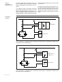
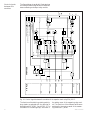
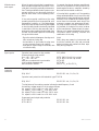
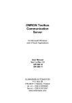
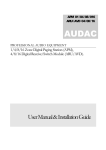
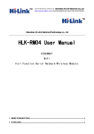
SPAJ 160 C
Capacitor protection relay
User´s manual and Technical description
3I >
∆I
3I <
2
I n = 1A
I n = 1A
f n = 50Hz
5A ( I )
5A (∆I )
I
5
60Hz
L1
I
L2
I
L3
∆I c
IRF
SPAJ 160 C
80...265V –
~
18...80V –
RESET
STEP
I b >/I n
U aux
k
SPCJ 4D40
REGISTERS
0
1
2
3
4
5
6
7
8
9
0
0
0
/I n
I L2 / I n
I L3 / I n
t (I a > )[ % ]
t (I b > )[ % ]
∆I c / ∆I n [ % ]
t (∆ I 1 > )[ % ]
t (∆ I 2 > )[ % ]
t (I < )[ % ]
I
L1
I a > [% I b ]
t a [ min ]
OPERATION IND.
I < /I n
t < [ s]
0
1
2
3
4
5
6
7
8
9
t rec [ min ]
I a >ALARM
∆ I 1 > [% ∆ I n ]
t ∆ 1 [ s]
I b >START
I b >TRIP
∆ I 2 > [% ∆ I n ]
k∆ 2
∆I 1 > ALARM
∆I 2 > START
∆I 2 > TRIP
I < OPERATION
∆I
cs
[% ∆ I n ]
PROGRAM
SGF
SGB
RECONN. INH.
EXTERN. TRIP
SGR
RS 421
ABB Automation
Ser.No.
0128A
0127A
TRIP
SPCJ 4D40
1MRS 750064-MUM EN
Issued 95-05-02
Modified 97-10-16
Version D
Checked GL
Approved YK
SPAJ 160 C
Capacitor protection relay
Data subject to change without notice
Contents
Characteristics ................................................................................................................ 2
Area of application (modified 97-10) ............................................................................... 3
Description of operation (modified 96-11) ...................................................................... 5
Connection diagram ....................................................................................................... 7
Connections ................................................................................................................... 9
Control signals between modules .................................................................................. 10
Abbreviations of signal names . ..................................................................................... 11
Operation indicators ..................................................................................................... 12
Power supply and output relau module ......................................................................... 14
Technical data (modified 96-11) .................................................................................... 15
Maintenance and repairs ............................................................................................... 18
Spare parts .................................................................................................................... 18
Ordering numbers ........................................................................................................ 18
Dimensions and instructions for mounting .................................................................. 19
Information required with order ................................................................................... 19
The complete user's manual also includes the following documents:
General characteristics of D-type relay module
Capacitor bank relay module type SPCJ 4D40
Characteristics
One-, two- and three-phase overload stage with
definite time charcteristic
One-, two- and three-phase overload stage with
inverse (ANSI) time charcteristic
Phase unbalance protection stage with definite
time charcteristic
Phase unbalance protection stage with inverse
time charcteristic
Undercurrent protection for detection of capacitor disconnection. Reconnection time with wide
setting range
Compensation for natural unbalance current
2
1MRS 750066-MUM EN
1MRS 750065-MUM EN
Fully selectable output relay configuration
Easy selection of appropriate operational scheme
for various applications
Numerical display of setting values, current
measured values, memorized values etc.
Continuous self-supervision of hardware and
software
Optical serial communication over the SPA bus
provides access from a higher level central unit
to all set and measured values and to memorized fault values. Various events can also be selected to be automatically read by a control data
communicator and printed out.
ABB Automation
Area of
application
(modified 97-10)
The main application area for the relay is to
protect capacitor banks intended for reactive
power compensation and filtering of the harmonics.
The capacitor banks are usually protected
against overload produced by harmonic currents
and overvoltage caused by internal faults in the
bank. A protection against reconnection of a
charged capacitor to a live network should also
be included. All these functions can be found
in SPAJ 160 C.
An earth-fault and overcurrent protection is often used for selective network protection. In this
case an overcurrent and earth-fault protection
relay from the SPACOM-family can be connected to the same current transformer as SPAJ
160 C.
Application
examples
3I>>
eg.
SPAA 341 C1
I
3I/U>
I/U<
IN-N
SPAJ 160 C
Fig.1. Protection of a capacitor bank connected as a double-star in a distribution network with
three-phase current measurement.
2I>>
I
e.g.
SPAA 120 C or
SPAA 121 C
2I/U>
I/U<
IN-N
SPAJ 160 C
Fig.2. Protection of a capacitor bank connected as a double-star in a distribution network with
two-phase current measurement.
ABB Automation
3
3I>>
I
e.g.
SPAJ 140 C or
SPAJ 141 C
3I/U>
I/U<
IN-N
SPAJ 160 C
Fig.3. Protection of a capacitor bank connected as a double-star in an industrial network with
two- or three-phase current measurement. In this case a non-directional earth-fault protection is
used.
1I>>
I
e.g.
SPAA 120 C or
SPAA 121 C
1I/U>
I/U<
IN-N
SPAJ 160 C
Fig.4. Protection of a one-phase bridge connected capacitor filter bank.
4
ABB Automation
Description of
operation
(modified 96-11)
The protective relay measures the phase currents
of the capacitor bank one-, two- or three phase.
The currents are internally transformed by the
relay to signals that will be directly proportionally to the voltages over the bank.
The relay is also measuring the unbalance current that may arise in a capacitor bank. The input current is in this case measured by a current
transformer connected between the starpoints
in a double-star connection according to fig. 5
or between the branches in a single-phase bridge
connection according to fig. 6.
Fig. 5.
Fig. 6.
The protective relay is a multifunction type of
relay and includes functions for overload protection, unbalance protection and undercurrent
protection combined with reconnection inhibit
to prevent reconnection of a charged capacitor
bank to a live network.
The overload protection is mainly a overvoltage
protection. It measures peak values with the
measured harmonics up to and including the
13th order. The overload protection includes
two stages. One stage is alarming and the other
is for tripping. The trip stage is based on inverse time characteristic and the inverse curve
is based on ANSI/IEEE C37.99 and IEC 8711 recommendations for the capacitor banks voltage withstand related to time. The gradient of
the curve can be changed by a k-factor within
the range 0.2...2.0.
ABB Automation
The alarm stage has a definite time characteristic. Both the starting value and the operating
time are available for setting. To match the relay to the rated current of the capacitor bank a
correction setting value is available. By using
this setting value it is possible to multiply the
signal from the current transformers by a factor
within the range 0.30...1.50.
The undercurrent protection, operating with
definite time characteristic, is detecting a possible undercurent in the capacitor bank. When
all three phase currents are opeating below the
starting value and the operating time has elapsed
the output alarm will be activated. The reconnection inhibit function connected to the undercurrent protection will be activated at the
same time. The reconnection inhibit signal will
be active until the set time has elapsed and is
used to inhibit the reconnection of a charged
capacitor bank to a live network. Both the starting value and the operating time for the undercurrent protection and the setting time for the
reconnection inhibit are available for setting.
The unbalance protection measures only the
basic frequency component of the current. The
protection function includes two stages of which
one is alarming and the other tripping. To improve unbalance detection in the capacitor bank
the relay is provided with a settable compensation of natural unbalance. Both the amplitude
and phase angle are compensated. The trip stage
is based on inverse time characteristic and the
curve has similar gradient to the normal inverse
curve.The starting value can be set within the
range 2...80% of the nominal input current of
the relay. The gradient of the curve can be
changed by the k-factor within the range 0.1...1.
It is possible to increase the inverse characteristic time by a factor 10 by setting switch SGF/6
to position 1.
The signal stage has a definite time characteristic. Both the starting value and the operating
time are available for setting. By using the unbalance compensation natural unbalance currents within the range 1...20% of the relays
nominal input current can be compensated.
By appropriate programming of the output relay matrix, various starting, alarm or reconnection inhibit signals are received as contact functions. This contact information is used e.g. for
the blocking of co-operating protective relays
located upstream, for connection to annunciation units etc.
5
The capacitor bank relay contains one external
logic control input, which is activated by a control signal of the auxiliary voltage level. The influence of the control input on the relay is determined by programming switches of the measuring module. The control input can be used
either for blocking one or more of the protective stages, for carrying out an external trip order, for inhibiting a reconnection attempt or/
and for resetting a latched output relay in the
manual reset mode.
The protective relay is provided with a manmachine interface on the front panel. The manmachine interface shows relay activation's, measured values, maximum value registrations, starting counters, time counters and setting values.
All changes of setting values can be made by
using the push-buttons on the front panel.
Through the serial bus the man-machine communication can be obtained either by using a
PC with a setting tool program, a SCS local
control system or a microSCADA remote control system.
TRIP
IL1
OVERLOAD PROTECTION
SIGNAL 1
IL2
IL3
∆I
COMPENSATION FOR NATURAL
PHASE UNBALANCE
CAPACITOR BANK PROTECTION
WITH ALARM/TRIP STAGE
UNDERCURRENT DETECTION
FOR RECONNECTION INHIBIT
SIGNAL 2
51N
START
RECOCONNECTION
ENABLE
37
IRF
CONTROL
INPUT BS1
RECONNECTION INHIBIT TIMER
62
SERIAL I/O
SERIAL COMMUNICATION
Fig. 7. Checking functions of the capacitor bank overload and unbalance prot. relay type
SPAJ 160 C.
6
ABB Automation
Connection
diagram
L1
L2
L3
0
-
I
-
I
0
+
+ (~)
Uaux
- (~)
CONTROL.
INPUT BS
5A
1A
5A
1A
5A
1A
1 2 3 4 5 6 7 8 9 25 26 27
5A
1A
63
11
10
+
RECONNECTION
INHIBIT
+
IRF
61 62
≅
+
70 71 72
74 75
F
-
SIGNAL 2
SIGNAL 1
77 78
80 81
68 69
TRIP
SERIAL
PORT
+
+
+
_
START
Tx
SPA-ZC_
Rx
E
65 66
+
+
+
D
C
B
SS1
SS2
SS3
A
U2 SPTU_R2
TS1
1
TS2
TRIP
U3
1
1
1
1
R
1
SGF/1
SGR1/5
SGR1/6
SGR1/7
SGR1/8
SGR2/8
SGR2/1
SGR2/2
SGR2/3
SGR2/4
SGR2/5
SGR2/6
SGR2/7
T8
IRF
SGR1/1
SGR1/2
SGR1/3
SGR1/4
SGB/7
SGB/8
3Ia>
T1
SGB/1
T2
3Ib>
T3
T4
SGB/2
SGB/3
T5
∆I2
SGF/2
∆I1
T6
3I<
T7
SGB/4
RECONN. INHIBIT
SGB/5
SGB/6
SPAJ 160 C
T9
EXTERNAL TRIP
RELAY RESET
I/O
U1
SPCJ 4D40
Fig. 8. Complete connection diagram for the capacitor bank protection relay SPAJ 160 C with all
the relay matrix and blocking/control input programming switches shown.
Uaux
A, B, C, D, E, F
IRF
SGB1
TRIP
SIGNAL 1
SIGNAL 2
START
RECONN. INHIBIT
U1
U2
U3
Rx Tx
T1...T9
SPA-ZC-
ABB Automation
Auxiliary voltage
Output relays
Self-supervision
Switchgroup for the configuration of the blocking and control signals
Trip output relay, output 65-66
Signal on tripping
Signal on tripping
Signal on starting
Connection inhibited in fault conditions
Capacitor bank protection relay module SPCJ 4D40
Power supply and output relay module SPTU 240 R2 or SPTU 48 R2
with a normally open trip contact
Input module SPTE 4E3
Serial communication interface
Operation indications
Bus connection module
7
Rx
Tx
1
61
2
62
3
63
4
65
5
66
6
74
7
75
8
70
9
71
68
69
77
78
80
81
Made in Finland
25 72
26 10
27 11
Fig. 9. Rear view of relay SPAJ 160 C
8
ABB Automation
Connections
Terminal
Function
1-2
1-3
4-5
4-6
7-8
7-9
25-26
25-27
Phase current IL1, 5 A
Phase current IL1, 1 A
Phase current IL2, 5 A
Phase current IL2, 1 A
Phase current IL3, 5 A
Phase current IL3, 1 A
Phase unbalance current 5 A
Phase unbalance current 1 A
61-62
Auxiliary supply voltage. At d.c. auxiliary supply voltage the positive lead is connected to terminal 61.
63
Protective earth
10-11
Blocking- and control input. Can be used as an external blocking input inhibiting
overload, phase unbalance or undercurrent protection. As an control input it can
be used for an external trip signal, for unlatching the trip relay and for the reconnection inhibit relay.
The function is selected with SGB-switches in the protection relay module.
65-66
Output relay A is a heavy duty relay which provides CB tripping commands.
A latching function of the output relay A can be selected by means of switches
SGB1/6 and SGB1/7. Switch SGB1/6 gives a latching function after an overload
tripping. Switch SGB1/7 provides a latching function after a phase unbalance trip.
The latched output relay can be reset locally or by remote control.
The undercurrent unit can be made tripping with switch SGF/2. Also the overload
stage Ia> can be made tripping with switch SGF/1.
68-69
The signals to be routed to output relays B and C are selected with switches 5...8 of
80-81 switchgroup. The signals to be routed to output relays B and C are selected
with switches 5...8 of switchgroup SGR1 and switches 1...8 of switchgroup SGR2
of the measuring module. Normally overload stage Ib> start signal is linked to
relay C and the overload stage Ia> alarm signal is linked to output relay B.
77-78
The signals to be routed to the output relay D are selected by means of switches
1...4 of switchgroup SGR1. Switch SGR1/1 links the overload Ia> alarm, switch
SGR2/2 links the oveload Ib> start, switch SGR2/3 links the phase unbalance
alarm of stage ∆I1> and switch SGR2/4 links the phase unbalance start signal of
stage ∆I2> to output relay D.
74-75
Output relay E is a heavy duty output relay capable of controlling a circuit breaker.
Relay E is normally used for controlling the reconnection of the capacitor bank. If
the reconnection inhibit signal is active the output relay E prevents a reconnection
attempt of the capacitor bank. This also applies to a condition where the protective relay is out of auxiliary voltage or the relay is faulty.
70-71-72 Output relay F operates as an self-supervision output relay. Under normal conditions the relay is operated and the contact gap 70-72 is closed. If a fault is detected by the self-supervision system, or if the auxiliary supply fails, the output
relay drops off, providing an alarm signal by closing the NO contact 71-72.
The relay is interfaced with the SPA serial communication bus through a 9-pole, D-type
subminiature connector located at the rear panel
of the relay. By means of the bus connection
ABB Automation
modules SPA-ZC21 or SPA-ZC17 the relay can
be linked to the serial bus and further to a control data communicator, e.g. SACO 148D4 or
SRIO 500/1000M.
9
Control signals
between the
modules
The figure below schematically illustrates how
the closing and alarm signals are connected between measuring and output relay module.
IL1
IL2
IL3
BS1
BS2
RRES
∆I
SGB1..3 / 1
SGB1...3 / 2
∆Ics
COMP
∆Ic
Ia>
Ib>
∆I1>
∆I2>
I<
EXTERNAL TRIP
RECONNECTION INHIBIT
SGB1...3 / 3
SGB1...3 / 4
TRIP INDICATOR RESET
COMPLETE RELAY RESET
t<
ta
70 ms
k
t∆1
70 ms
k∆2
200ms
t rec
TRIP INDICATOR + OUTPUT RELAY RESET
SGB1...3 / 5
SGB2...3 / 6
SGB2...3 / 7
SGB1...3 / 8
SGR1 / 1
SGR2 / 1
SGR1 / 5
SGF / 1
SGR1 / 2
SGR2 / 2
SGR2 / 3
SGR1 / 6
SGR1 / 3
SGR2 / 4
SGR1 / 4
SGR2 / 5
SGR2 / 6
SGR1 / 7
SGR2 / 7
SGR1 / 8
SGF / 2
SGR2 / 8
SGB1 / 6
1
SGB1 / 7
1
RESET+.
PROGRAM
RESET+.
PROGRAM
RESET
1
1
TRIP
SPCJ 4D40
TS1
SS1
AR2
SS2
SS3
AR1
TS2
IRF
RECONN.
INHIBIT
START
SIGNAL 2
SIGNAL 1
TRIP
SPTU_R2
F
E
D
C
B
A
Fig. 10. Control signals between the modules of the capacitor bank relay SPAJ 160 C.
The functions of the blocking, starting and tripping signals are selected with the switches of
switchgroups SGF, SGB1...3 and SGR1...2. The
checksums of the switchgroups, are found in
10
the setting menu of the measuring relay module. The functions of the different switches are
explained in the user's manual of the measuring module SPCJ 4D40.
ABB Automation
Abbreviations of
signal names
ABB Automation
IL1, IL2, IL3
∆I
∆Ic
BS1, BS2 ,RRES
SS1
SS2
SS3
TS1
TS2
AR1...3
IRF
SS1
SGF
SGB1...3
SGR1...2
Rx/Tx
Phase currents
Phase unbalance current
Compensated phase unbalance current
External blocking or resetting signals
Starting Signal 1
Starting Signal 2
Starting Signal 3
Tripping Signal 1
Tripping Signal 2
Auto-Reclose starting signals (not used in SPAJ 160 C)
Internal Relay Fault signal
Starting Signal 1
Switch Groups for functions
Switch Groups for blockings
Switch Groups for relay configuration
Receiver/Transmitter channel
11
Operation
indicators
3I >
∆I
3I <
2
I n = 1A
I n = 1A
f n = 50Hz
5A ( I )
5A (∆I )
I
5
60Hz
L1
I
L2
I
L3
∆I c
IRF
SPAJ 160 C
80...265V –
~
18...80V –
RESET
STEP
I b >/I n
U aux
k
SPCJ 4D40
REGISTERS
0
1
2
3
4
5
6
7
8
9
0
0
0
/I n
I L2 / I n
I L3 / I n
t (I a > )[ % ]
t (I b > )[ % ]
∆I c / ∆I n [ % ]
t (∆ I 1 > )[ % ]
t (∆ I 2 > )[ % ]
t (I < )[ % ]
I
L1
I a > [% I b ]
t a [ min ]
OPERATION IND.
I < /I n
t < [ s]
0
1
2
3
4
5
6
7
8
9
t rec [ min ]
I a >ALARM
∆ I 1 > [% ∆ I n ]
t ∆ 1 [ s]
I b >START
I b >TRIP
∆ I 2 > [% ∆ I n ]
k∆ 2
∆I 1 > ALARM
∆I 2 > START
∆I 2 > TRIP
I < OPERATION
∆I
cs
[% ∆ I n ]
PROGRAM
SGF
SGB
RECONN. INH.
EXTERN. TRIP
SGR
RS 421
Ser.No.
0128A
0127A
TRIP
SPCJ 4D40
A) The indicator TRIP is lit when one of the
protection stages operates. When the protection
stage returns, the red indicator remains alight.
B) If the display is dark when one of the protection stages Ia> or Ib> request for tripping,
the faulty phase is indicated with a yellow LED.
If, for instance, the TRIP indicator glows red,
12
Indication
Explanation
1
2
3
4
5
6
7
8
9
Ia> alarm
Ib> start
Ib> trip
∆I1> alarm
∆I2> start
∆I2> trip
I< operation
trec
EXT.TRIP
and the indicators IL1 and IL2 are ON at the
same time, overcurrent has occurred on phase
L1 and L2.
C) Besides being a code number at data presentation, the leftmost red digit in the display serves
as a visual operation indicator. An operation
indicator is recognized by the fact that the red
digit alone is switched on. The operation indication from a start or the reconnection inhibit
is always replaced by a new operation indication. On the other hand an operation indication from a stage connected to the trip relay A
can not be replaced by a new operation indication. In order to enable reading of actual current levels etc. when reconnection time is running, it is possible to acknowledge the indication 8 while the unit is still activated. The same
applies to the external trip indication 9. In these
cases the indications are memorized and reappear when the display is dark. Operation indicator 8 is automatically reset when the capacitor bank is reconnected. The following table,
named OPERATION IND. on the relay front
panel, is a key to the operation indicator code
numbers used.
= The overload stage Ia> has given an alarm
= The overload stage Ib> has started
= The overload stage Ib> has tripped
= The stage ∆I1> has given an alarm
= The stage ∆I2> has started
= The stage ∆I2> has tripped
= The stage I< has operated
= The reconnection inhibit is active, indication is self-reset
= A trip from an external relay has been carried out via the relay
ABB Automation
D) The operation indicator on the display and
the "TRIP" indicator persist when the protective stage returns to normal. The indicators are
reset by pushing the RESET/STEP push-button.
Further, the indicators may be reset via the external control input 10-11 by applying a control voltage to the input, provided that the
switch SGB1/8 is in position 1.
The basic protective relay functions are not depending on the state of the operation indicators, i.e. reset or non-reset. The relay is permanently operative.
If stage Ib> or ∆I2> starts, but no tripping occurs because the energizing quantity goes below the starting level before the delay circuit
times out, the starting indications are automatically switched off. However, by means of the
switches SGF/3...4 the starting indications may
be persistent which means that they are to be
reset by pushing the RESET/STEP push-but-
ABB Automation
ton. The persistent indications are obtained
through the following programming:
Switch SGF/3 = 1 Starting indication on Ib>
persistent
Switch SGF/4 = 1 Starting indication on ∆I2>
persistent
On delivery from factory the switches SGF/3...4 = 0
E) The self-supervision alarm indicator IRF indicates that the self-supervision system has detected a permanent fault. The indicator activates
with a red light about 1 minute after the fault
has been detected. At the same time the plug-in
module delivers a signal to the self-supervision
system output relay of the protection assembly.
Additionally, in most cases, a fault code showing the nature of the fault appears on the display of the module. The fault code, consists of
a red figure one and a green code number, this
cannot be erased from the display of the module by resetting. When a fault occurs, the fault
code should be recorded and stated when service, is ordered.
13
Power supply
and output
relay module
To be able to operate the relay needs a secured
auxiliary voltage supply. The power supply module forms the voltages required by the measuring relay module and the auxiliary relays. The
withdrawable power supply and output relay
module is located behind the system front panel,
which is fixed by means of four cross-slotted
screws. The power supply and output relay
module contains the power supply unit, all output relays, the control circuits of the output relays and the electronic circuitry of the external
control signals.
The power supply and output relay unit can be
withdrawn after removing the system front
panel. The primary side of the power supply
module is protected with a fuse, F1, located on
the PCB of the module. The fuse size is 1 A
(slow).
The power supply unit is a transformer connected, i.e. galvanically isolated primary and
secondary side, flyback-type dc/dc converter. It
forms the dc secondary voltages required by the
measuring relay module; that is +24 V, ±12 V
and +8 V. The output voltages ±12V and +24 V
are stabilized in the power supply module, while
the +5 V logic voltage required by the measuring relay module is formed by the stabilizer of
the relay module.
+8V
1 A slow
Uaux
+12V
80...265 V ac & dc
18...80 V dc
-12V
+24V
Unstabilized logics
voltage
Operation amplifier
voltage
Output relay coil
voltage
Fig. 11. Voltage levels of the power supply module.
A green LED indicator Uaux on the system front
panel is illuminated when the power supply
module is in operation. The supervision of the
voltages supplying the electronics is placed in
the measuring module. If a secondary voltage
deviates from its rated value by more than 25 %,
a selfsupervision alarm will be established. An
alarm is also received when the power supply
module is withdrawn from the relay case, or
when the auxiliary power supply to the relay is
interrupted.
There are two versions of the power supply and
output relay modules available. For both types,
the secondary sides and the relay configurations
are identical, but the input voltage ranges differ.
14
Insulation test voltage between the primary and
the secondary side and the protective earth.
2 kV, 50 Hz, 1min
Rated power Pn
5W
Voltage ranges of the power supply modules:
- SPTU 240 R2
Uaux = 80 ... 265 V ac/dc
- SPTU 48 R2
Uaux = 18 ... 80 V dc
(on request)
The module SPTU 240 R2 can be used with
both ac and dc voltages. Module SPTU 48 R2
is designed for dc supply only. The auxiliary
voltage range of the power supply module of
the relay assembly is indicated on the system
front panel.
ABB Automation
Technical data
(modified 96-11)
Energizing inputs
Phase and neutral current inputs, terminals
Rated current In
Thermal withstand capability
- continuously
- for 1 s
Dynamic current withstand, half-wave value
Input impedance
Phase current monitoring range
Phase unbalance current monitoring range
Rated frequency
Output contact ratings
Reconnection enable and trip contact
Terminals
- Rated voltage
- Carry continuously
- Make and carry for 0.5 s
- Make and carry for 3.0 s
- Breaking capacity for dc, when the control
circuit time-constant L/R < 40ms,
at 48/110/220 V dc control circuit voltage
Contact material
Start and signalling contacts
Terminals
- Rated voltage
- Carry continuously
- Make and carry for 0.5 s
- Make and carry for 3.0 s
- Breaking capacity for dc, when the control
circuit time-constant L/R < 40ms,
at 48/110/220 V dc control circuit voltage
Contact material
External control inputs
Blocking and command inputs
External control voltage level
Typical control current of input circuit
Power supply and output relay module
Supply and relay module, type SPTU 240 R2
Supply and relay module, type SPTU 48 R2
Power consumption under quiescent/operating
conditions
ABB Automation
1-3, 4-6, 7-9, 25-27
1A
1-2, 4-5, 7-8, 25-26
5A
4A
100 A
250 A
< 100 mΩ
0...8.5 x In
0...212% ∆In
50/60 Hz
20 A
500 A
750 A
< 20 mΩ
65-66, 74-75
250 V dc/ac
5A
30 A
15 A
5A/3A/1A
AgCdO2
70-71-72, 68-69, 77-78, 80-81
250 V dc/ac
5A
10 A
8A
1A / 0.25A / 0.15A
AgCdO2
10-11
18...265 V dc or 80...265 V ac
2 mA
80...265 V dc/ac
18...80 V dc (on request)
4W/6W
15
Protection units of module SPCJ 4D40
Overload stage Ib>
Starting current Ib>
Starting time
Operation characteristic
Time multiplier k
Resetting time
Drop-off/pick-up ratio
Operation time accuracy
(k = 1.0 and Ib> = 0.50…1.50 x In)
Operation accuracy
Shortest possible trip time
Overload stage Ia>
Starting current Ia>
Operating time
Resetting time
Drop-off/pick-up ratio
Operation time accuracy
Operation accuracy
Undercurrent stage I<
Starting current I<
Operating time
Reconnection time
Pulse shaped tripping signal,
pulse length
Pick-up/drop-off ratio
Operation time accuracy
Operation accuracy
Phase unbalance ∆I1>, Stage 1
Starting current ∆I1>
Operating time
Resetting time
Drop-off/pick-up ratio
Operation time accuracy (∆Ics = 0)
Operation accuracy (∆Ics = 0)
0.30...1.50 x In
<80 ms
ANSI inverse
0.2...2.0
<100 ms
>0.95
±10% of theoretical value or ±50 ms
±3% of set value
~100 ms
80...120% x Ib>
0.50...100 min
<250 ms
>0.95
±2% of set value
±3% of set value
0.10...0.70 x In
1.0...100 s
0.50...100 min
~200 ms
<1.1
±2% of set value or ±75 ms
±3% of set value within range 0.25...0.70 x In
1.0...100% ∆In *)
1.0...300 s
<100 ms
>0.90
±2% of set value or ±75 ms
±3% of set value within range 1.5...100% ∆In
Phase unbalance ∆I2>, Stage 2
Starting current ∆I2>
Starting time
Operation characteristic
Time multiplier k∆2
Resetting time
Drop-off/pick-up ratio
Operation time accuracy of theoretical
characteristic (∆Ics = 0)
Operation accuracy (∆Ics = 0)
Shortest possible trip time
7.5% or ±35 ms
±3% of set value
~100 ms
Setting of compensation
Operation accuracy
0.0...20.0% ∆In
<3% of ∆In
2.0...80.0% ∆In *)
<70 ms
Inverse time
0.1...1.0
<100 ms
>0.90
*) minimum recommended: 3.0% ∆In
16
ABB Automation
Data transmission
Transmission mode
Data code
Data transfer rate, selectable
Electrical/optical bus connection module
powered from the host relay
- for plastic core cables
- for glass fibre cables
Electrical/optical bus connection module
powered from the host relay or an external
power source
- for plastic core cables
- for glass fibre cables
Test voltages *)
Dielectric test voltage according to IEC 255-5
Impulse test voltage according to IEC 255-5
Insulation resistance according to IEC 255-5
Disturbance tests *)
High-frequency (1MHz) disturbance test
according to IEC 255-22-1, class III
- common mode
- differential mode
Fast transients according to IEC 255-22-4,
class III and IEC 801-4, level 4
- power supply inputs
- other inputs
Electrostatic discharge test according to
IEC 255-22-2 and IEC 801-2, class III
- air discharge
- contact discharge
Environmental conditions
Specified ambient service temperature range
Temperature influence on the operating values
of the relay over the specified ambient service
temperature range
Long term damp heat withstand according
to IEC 68-2-3
Transport and storage temperature range
Degree of protecting by enclosure of the relay case
as per IEC 529 when panel mounted
Mass of the relay
Fibre optic serial bus
ASCII
4800 Bd or 9600 Bd
SPA-ZC 21 BB
SPA-ZC 21 MM
SPA-ZC 17 BB
SPA-ZC 17 MM
2.0 kV, 50 Hz, 1 min
5 kV, 1.2/50 µs, 0.5 J
>100 MΩ, 500 V dc
2.5 kV
1.0 kV
4 kV, 5/50 ns
2 kV, 5/50 ns
8 kV
6 kV
-10 ... +55 oC
< 0.2 %/ oC
< 95 % at 40 oC for 56 d/a
-40 ... +70 oC
IP 54
3.5 kg
*) The insulation and disturbance tests do not apply to the serial port, which is used for the bus
connection module only.
ABB Automation
17
Maintenance
and repair
When the synchrocheck relay is operating under the conditions specified in the section "Technical data", the relay is practically maintenancefree. The relay modules include no parts or components subject to an abnormal physical or
electical wear under normal operating conditions.
If the environmental conditions at the relay
operating site differ from those specified, as to
temperature, humidity, or if the athmosphere
around the relay contains chemically active gases
or dust, the relay should to be visually inspected
in association with the relay secondary test or
whenever the relay modules are withdrawn from
the case. At the visual inspection the following
things should be noted:
Spare parts
Ordering
numbers
On request, the relay can be given a special treatment for the protection of the printed circuit
boards against stress on materials, caused by
abnormal environmental conditions.
If the relay fails in operation or if the operating
values remarkable differ from those of the relay
specifications, the relay should be given a proper
overhaul. Minor measures can be taken by personnel from the instrument work-shop of the
customer's company, e.g. replacement of auxiliary relay modules. All major measures involving overhaul of the electronics are to be taken
by the manufacturer. Please contact the manufacturer or his nearest representative for further
information about checking, overhaul and
recalibration of the relay.
- Signs of mechanical damage on the relay modules, contacts and relay case
- Accumulation of dust inside the relay cover
or case; remove by flowing air carefully
- Rust spots or signs of erugo on terminals, case
or inside the relay
Note!
Static relays are measuring instruments and
should be handled with care and protected
against moisture and mechanical stress, especially during transport.
Capacitor bank protection relay module
Power and output relay module
Uaux = 80 ... 265 V ac/dc
Uaux = 18 ... 80 V dc
Relay box, complete with input module
Input module as separate part
Bus connection module
SPCJ 4D40
SPTU 240 R2 for NO trip contact
SPTU 48 R2 for NO trip contact
SPTK 4E3
SPTE 4E3
SPA-ZC 17_ or SPA-ZC 21_
Capacitor bank protection without testswitch
SPAJ 160 C
RS 611 051 - AA, CA, DA, FA
Capacitor bank protection with testswitch type RTXP 18
SPAJ 160 C
RS 611 251 - AA, CA, DA, FA
The last letters of the ordering number indicate the rated frequency fn and
the auxiliary voltage range Uaux of the relay as follows:
AA equals fn = 50 Hz and Uaux = 80...265 V ac/dc
CA equals fn = 50 Hz and Uaux = 18...80 V ac/dc
DA equals fn = 60 Hz and Uaux = 80...265 V ac/dc
FA equals fn = 60 Hz and Uaux = 18...80 V ac/dc
Power supply and output relay modules:
SPTU 240 R2
SPTU 48 R2
18
RS 911 021 - AA
RS 911 021 - BA
ABB Automation
Dimensions and
instructions for
mounting
The relay case is completely with a hinged
gasketed, clear, UV-stabilized polycarbonate
cover with a sealable fastening screw. The degree of protection by enclosure of the cover is
also IP 54.
The relay is housed in a normally flush-mounted
case. The relay can also be arranged for semiflush mounting with the use of a 40 mm, 80 mm
or 120 mm raising frame, which reduces the
depth behind the panel by the same dimension.
The type designation of the raising frames are
SPA-ZX 111 for the 40 mm frame, SPA-ZX
112 for the 80 mm frame and SPA-ZX 113 for
the 120 mm frame. A surface mounting case
SPA-ZX 117 is also available.
A terminal strip and two multipole connectors
are mounted on the back of the relay case to
facilitate all input and output connections. To
each heavy duty terminal, i.e. measuring input,
power or closing output, one 6 mm2, one 4 mm2
or one or two 2.5 mm2 wires can be connected.
No terminal lugs are needed. The three signalling inputs are available on a six pole detachable connector and the serial bus connection is
using a 9-pin D-type connector.
The relay case is made of an extruded, beige
aluminium profile.
A cast aluminium alloy mounting frame with
rubber gasket provides a degree of protection
by enclosure to IP 54 between the relay case
and the panel surface when the relay is panel
mounted.
250
216
186
142
162
139 ±1
129 ±1
a
SPA-ZX 111
SPA-ZX 112
SPA-ZX 113
1. Quantity and type designation
2. Ordering number
3. Rated frequency
4. Auxiliary voltage
5. Accessories
6. Special requirements
ABB Automation
b
Panel cut-out
Raising frame
Information
required with
order
34
136
30
a
b
176
136
96
74
114
154
Example
15 pcs SPAJ 160 C
RS 611 051 - AA
fn = 50 Hz
Uaux = 110 V dc
15 pcs matching modules SPA-ZC 21 MM
2 pcs fibre optical cables SPA-ZF MM 100
19
1MRS 750064-MUM EN
ABB Substation Automation Oy
P.O.Box 699
FIN-65101 VAASA
Finland
Tel. +358 (0)10 22 4000
Fax.+358 (0)10 22 41094
www.abb.com/fi