1
User’s
Manual
Differential Pressure and
Pressure Transmitters
EJ110, EJ120,
EJ130, EJ310,
EJ430, and EJ440
IM 01C25B01-01E
IM 01C25B01-01E
12th Edition
i
Differential Pressure and Pressure Transmitters
EJ110, EJ120, EJ130,
EJ310, EJ430, and EJ440
IM 01C25B01-01E 12th Edition
Contents
1.
Introduction................................................................................................ 1-1
Regarding This Manual................................................................................................. 1-1
2.
1.1
Safe Use of This Product ................................................................................. 1-2
1.2
Warranty.............................................................................................................. 1-3
1.3
ATEX Documentation........................................................................................ 1-4
Handling Cautions..................................................................................... 2-1
2.1
Model and Specifications Check...................................................................... 2-1
2.2
Unpacking........................................................................................................... 2-1
2.3
Storage................................................................................................................ 2-1
2.4
Selecting the Installation Location ................................................................. 2-2
2.5
Pressure Connection......................................................................................... 2-2
2.6
Waterproofing of Cable Conduit Connections............................................... 2-2
2.7
Restrictions on Use of Radio Transceivers.................................................... 2-2
2.8
Insulation Resistance and Dielectric Strength Test....................................... 2-2
2.9
Installation of an Explosion-Protected Instrument........................................ 2-3
2.9.1
FM Approval........................................................................................ 2-4
2.9.2
CSA Certification................................................................................. 2-5
2.9.3
ATEX Certification............................................................................... 2-7
2.9.4
IECEx Certification............................................................................ 2-11
2.10
EMC Conformity Standards............................................................................ 2-12
2.11
Pressure Equipment Directive (PED)............................................................ 2-12
2.12
Low Voltage Directive...................................................................................... 2-13
3.
Component Names................................................................................... 3-1
4.
Installation.................................................................................................. 4-1
4.1
Precautions ....................................................................................................... 4-1
4.2
Mounting ............................................................................................................ 4-1
4.3
Changing the Process Connection.................................................................. 4-2
4.4
Swapping the High/Low-pressure Side Connection...................................... 4-3
4.4.1
Rotating Pressure-detector Section 180° .......................................... 4-3
4.4.2
Using the Communicator.................................................................... 4-3
4.5
Rotating Transmitter Section............................................................................ 4-4
4.6
Changing the Direction of Integral Indicator ................................................. 4-4
12th Edition: June 2012 (YK)
All Rights Reserved, Copyright © 2004, Yokogawa Electric Corporation
IM 01C25B01-01E
ii
5.
Installing Impulse Piping.......................................................................... 5-1
5.1
5.2
6.
Connecting Impulse Piping to a Transmitter....................................... 5-1
5.1.2
Routing the Impulse Piping................................................................. 5-3
Impulse Piping Connection Examples............................................................ 5-4
6.1
Wiring Precautions............................................................................................ 6-1
6.2
Selecting the Wiring Materials.......................................................................... 6-1
6.3
Connections of External Wiring to Terminal Box........................................... 6-1
6.3.1
Power Supply Wiring Connection....................................................... 6-1
6.3.2
External Indicator Connection............................................................ 6-1
6.3.3
Communicator Connection................................................................. 6-1
6.3.4
Check Meter Connection.................................................................... 6-2
6.3.5
Status Output Connection................................................................... 6-2
Wiring.................................................................................................................. 6-2
6.4.1
Loop Configuration............................................................................. 6-2
6.4.2
Wiring Installation................................................................................ 6-2
6.5
Grounding........................................................................................................... 6-3
6.6
Power Supply Voltage and Load Resistance.................................................. 6-3
Operation.................................................................................................... 7-1
7.1
Preparation for Starting Operation.................................................................. 7-1
7.2
Zero Point Adjustment...................................................................................... 7-2
7.2.1
Adjusting Zero Point for Differential Pressure Transmitters............... 7-3
7.2.2
Adjusting Zero Point for Gauge/Absolute Pressure Transmitters .... 7-3
7.3
Starting Operation............................................................................................. 7-3
7.4
Shutting Down the Transmitter........................................................................ 7-4
7.5
Venting or Draining Transmitter Pressure-detector Section........................ 7-4
7.6
8.
5.1.1
Wiring.......................................................................................................... 6-1
6.4
7.
Impulse Piping Installation Precautions......................................................... 5-1
7.5.1
Draining Condensate.......................................................................... 7-4
7.5.2
Venting Gas........................................................................................ 7-5
Setting the Range Using the Range-setting Switch....................................... 7-5
Maintenance............................................................................................... 8-1
8.1 Overview............................................................................................................. 8-1
8.2
Calibration Instruments Selection................................................................... 8-1
8.3
Calibration.......................................................................................................... 8-1
8.4
Disassembly and Reassembly......................................................................... 8-3
8.4.1
Replacing the Integral Indicator.......................................................... 8-3
8.4.2
Replacing the CPU Board Assembly.................................................. 8-4
8.4.3
Cleaning and Replacing the Capsule Assembly................................ 8-4
8.4.4
Replacing the Process Connector Gaskets........................................ 8-6
IM 01C25B01-01E
iii
8.5
9.
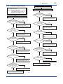
Troubleshooting................................................................................................. 8-6
8.5.1
Basic Troubleshooting........................................................................ 8-6
8.5.2
Troubleshooting Flowcharts................................................................ 8-7
8.5.3
Alarms and Countermeasures............................................................ 8-9
General Specifications............................................................................. 9-1
9.1
Standard Specifications.................................................................................... 9-1
9.2
Model and Suffix Codes.................................................................................... 9-6
9.3
Optional Specifications .................................................................................. 9-19
9.4
Dimensions....................................................................................................... 9-22
Revision Information
When using the Transmitters in a Safety Instrumented Systems(SIS)
application, refer to Appendix A in either IM 01C25T01-06EN for the
HART protocol or IM 01C25T03-01E for the BRAIN protocol.
IM 01C25B01-01E
1.
1-1
<1. Introduction>
Introduction
Thank you for purchasing the DPharp Differential
Pressure and pressure transmitter.
Your transmitter was precisely calibrated at the
factory before shipment. To ensure both safety and
efficiency, please read this manual carefully before
you operate the instrument.
NOTE
This manual describes the hardware
configurations of the transmitters listed in below.
For information on the software configuration
and operation, please refer to either
IM 01C25T03-01E for the BRAIN communication
type, or IM 01C25T01-06EN for the HART
communication type.
For FOUNDATION Fieldbus protocol type,
please refer to IM 01C25T02-01E.
Model
EJX110A
EJX120A
EJX130A
EJX310A
EJX430A
EJX440A
EJA110E
EJA120E
EJA130E
EJA310E
EJA430E
EJA440E
Style code
S3
S1
S2
S2
S2
S2
S1
S1
S1
S1
S1
S1
To ensure correct use of this instrument, read
both the hardware and software manuals
thoroughly before use.
WARNING
When using the transmitters in a Safety
Instrumented Systems (SIS) application, refer
to Appendix 1 in either IM 01C25T01-06EN for
the HART protocol or IM 01C25T03-01E for the
BRAIN protocol. The instructions and procedures
in this section must be strictly followed in order to
maintain the transmitter for this safety level.
NOTE
When describing the model name like EJ110,
it shows the applicability for both EJX110A and
EJA110E. The same representations are used
for the other models, too.
NOTE
Unless otherwise stated, the illustrations in
this manual are of the EJ110 differential
pressure transmitter. Users of the other models
should bear in mind that certain features of their
instrument will differ from those shown in the
illustrations of the EJ110.
Regarding This Manual
• This manual should be provided to the end
user.
• The contents of this manual are subject to
change without prior notice.
• All rights reserved. No part of this manual may
be reproduced in any form without Yokogawa’s
written permission.
• Yokogawa makes no warranty of any kind with
regard to this manual, including, but not limited
to, implied warranty of merchantability and
fitness for a particular purpose.
• If any question arises or errors are found, or if
any information is missing from this manual,
please inform the nearest Yokogawa sales
office.
• The specifications covered by this manual are
limited to those for the standard type under the
specified model number break-down and do not
cover custom-made instruments.
• Please note that changes in the specifications,
construction, or component parts of the
instrument may not immediately be reflected
in this manual at the time of change, provided
that postponement of revisions will not cause
difficulty to the user from a functional or
performance standpoint.
IM 01C25B01-01E
• Yokogawa assumes no responsibilities for this
product except as stated in the warranty.
• If the customer or any third party is harmed by
the use of this product, Yokogawa assumes
no responsibility for any such harm owing to
any defects in the product which were not
predictable, or for any indirect damages.
• The following safety symbols are used in this
manual:
1-2
<1. Introduction>
1.1 Safe Use of This Product
For the safety of the operator and to protect the
instrument and the system, please be sure to follow
this manual’s safety instructions when handling this
instrument. If these instructions are not heeded,
the protection provided by this instrument may be
impaired. In this case, Yokogawa cannot guarantee
that the instrument can be safely operated. Please
pay special attention to the following points:
(a) Installation
WARNING
Indicates a potentially hazardous situation which,
if not avoided, could result in death or serious
injury.
CAUTION
Indicates a potentially hazardous situation which,
if not avoided, may result in minor or moderate
injury. It may also be used to alert against unsafe
practices.
IMPORTANT
Indicates that operating the hardware or software
in this manner may damage it or lead to system
failure.
NOTE
Draws attention to information essential for
understanding the operation and features.
Direct current
• This instrument may only be installed by an
engineer or technician who has an expert
knowledge of this device. Operators are not
allowed to carry out installation unless they
meet this condition.
• With high process temperatures, care must
be taken not to burn yourself by touching the
instrument or its casing.
• Never loosen the process connector nuts when
the instrument is installed in a process. This can
lead to a sudden, explosive release of process
fluids.
• When draining condensate from the pressure
detector section, take appropriate precautions
to prevent the inhalation of harmful vapors and
the contact of toxic process fluids with the skin
or eyes.
• When removing the instrument from a
hazardous process, avoid contact with the fluid
and the interior of the meter.
• All installation shall comply with local installation
requirements and the local electrical code.
(b) Wiring
• The instrument must be installed by an
engineer or technician who has an expert
knowledge of this instrument. Operators are not
permitted to carry out wiring unless they meet
this condition.
• Before connecting the power cables, please
confirm that there is no current flowing through
the cables and that the power supply to the
instrument is switched off.
IM 01C25B01-01E
(c) Operation
• Wait 5 min. after the power is turned off, before
opening the covers.
(d) Maintenance
• Please carry out only the maintenance
procedures described in this manual. If you
require further assistance, please contact the
nearest Yokogawa office.
• Care should be taken to prevent the build up of
dust or other materials on the display glass and
the name plate. To clean these surfaces, use a
soft, dry cloth.
(e) Explosion Protected Type Instrument
• Users of explosion proof instruments should
refer first to section 2.9 (Installation of an
Explosion Protected Instrument) of this manual.
• The use of this instrument is restricted to those
who have received appropriate training in the
device.
• Take care not to create sparks when accessing
the instrument or peripheral devices in a
hazardous location.
(f) Modification
• Yokogawa will not be liable for malfunctions or
damage resulting from any modification made
to this instrument by the customer.
<1. Introduction>
1-3
1.2 Warranty
• The warranty shall cover the period noted on
the quotation presented to the purchaser at the
time of purchase. Problems occurring during
the warranty period shall basically be repaired
free of charge.
• If any problems are experienced with this
instrument, the customer should contact the
Yokogawa representative from which this
instrument was purchased or the nearest
Yokogawa office.
• If a problem arises with this instrument,
please inform us of the nature of the problem
and the circumstances under which it
developed, including the model specification
and serial number. Any diagrams, data and
other information you can include in your
communication will also be helpful.
• The party responsible for the cost of fixing the
problem shall be determined by Yokogawa
following an investigation conducted by
Yokogawa.
• The purchaser shall bear the responsibility for
repair costs, even during the warranty period, if
the malfunction is due to:
- Improper and/or inadequate maintenance by
the purchaser.
- Malfunction or damage due to a failure
to handle, use, or store the instrument in
accordance with the design specifications.
- Use of the product in question in a location
not conforming to the standards specified by
Yokogawa, or due to improper maintenance
of the installation location.
- Failure or damage due to modification or
repair by any party except Yokogawa or an
approved representative of Yokogawa.
- Malfunction or damage from improper
relocation of the product in question after
delivery.
- Reason of force majeure such as fires,
earthquakes, storms/floods, thunder/
lightening, or other natural disasters, or
disturbances, riots, warfare, or radioactive
contamination.
IM 01C25B01-01E
<1. Introduction>
1-4
1.3 ATEX Documentation
This is only applicable to the countries in European Union.
GB
DK
SK
CZ
I
LT
E
LV
NL
EST
PL
SF
SLO
P
H
F
BG
D
RO
S
M
GR
IM 01C25B01-01E
2.
2-1
<2. Handling Cautions>
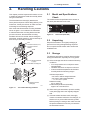
Handling Cautions
This chapter provides important information on how
to handle the transmitter. Read this carefully before
using the transmitter.
The transmitters are thoroughly tested at the
factory before shipment. When taking delivery of an
instrument, visually check them to make sure that
no damage occurred during shipment.
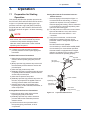
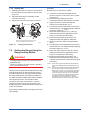
Also check that all transmitter mounting hardware
shown in figure 2.1 is included. If the transmitter
is ordered without the mounting bracket and the
process connector, the transmitter mounting
hardware will not be included. After checking the
transmitter, carefully repack it in its box and keep it
there until you are ready to install it.
Bolt
Process connector (Note 1)
Process connector
Gasket
U-bolt
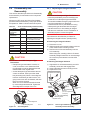
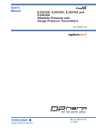
2.1 Model and Specifications
Check
The model name and specifications are written on
the name plate attached to the case.
F0202.ai
Figure 2.2
Name Plate (EJX110A)
2.2 Unpacking
Keep the transmitter in its original packaging to
prevent it from being damaged during shipment.
Do not unpack the transmitter until it reaches the
installation site.
2.3 Storage
The following precautions must be observed when
storing the instrument, especially for a long period.
Mounting bracket
(L type)
U-bolt nut
Transmitter mounting bolt
(a) Select a storage area which meets the following
conditions:
• It is not exposed to rain or subject to water
seepage/leaks.
• Vibration and shock are kept to a minimum.
• It has an ambient temperature and relative
humidity within the following ranges.
Ambient temperature:
–40* to 85°C without integral indicator
–30* to 80°C with integral indicator
* –15°C when /HE is specified.
Mounting bracket
(Flat type)
F0201.ai
Figure 2.1
Transmitter Mounting Hardware
Relative humidity:
0% to 100% R.H.
Preferred temperature and humidity:
approx. 25°C and 65% R.H.
(b) When storing the transmitter, repack it carefully
in the packaging that it was originally shipped
with.
(c) If the transmitter has been used, thoroughly
clean the chambers inside the cover flanges, so
that there is no process fluid remaining inside.
Before placing it in storage, also make sure that
the pressure-detector is securely connected to
the transmitter section.
IM 01C25B01-01E
2.4 Selecting the Installation
Location
The transmitter is designed to withstand severe
environmental conditions. However, to ensure
that it will provide years of stable and accurate
performance, take the following precautions when
selecting the installation location.
(a) Ambient Temperature
Avoid locations subject to wide temperature
variations or a significant temperature gradient.
If the location is exposed to radiant heat from
plant equipment, provide adequate thermal
insulation and/or ventilation.
(b) Ambient Atmosphere
Do not install the transmitter in a corrosive
atmosphere. If this cannot be avoided, there
must be adequate ventilation as well as
measures to prevent the leaking of rain water
and the presence of standing water in the
conduits.
(c) Shock and Vibration
Although the transmitter is designed to be
relatively resistant to shock and vibration, an
installation site should be selected where this is
kept to a minimum.
(d) Installation of Explosion-protected Transmitters
An explosion-protected transmitters is
certified for installation in a hazardous area
containing specific gas types. See subsection
2.9 “Installation of an Explosion-Protected
Transmitters.”
2.5 Pressure Connection
WARNING
• Never loosen the process connector bolts
when an instrument is installed in a process.
The device is under pressure, and a loss of
seal can result in a sudden and uncontrolled
release of process fluid.
• When draining toxic process fluids that have
condensed inside the pressure detector,
take appropriate steps to prevent the contact
of such fluids with the skin or eyes and the
inhalation of vapors from these fluids.
2-2
<2. Handling Cautions>
The following precautions must be observed
in order to safely operate the transmitter under
pressure.
(a) Make sure that all the process connector bolts
are tightened firmly.
(b) Make sure that there are no leaks in the impulse
piping.
(c) Never apply a pressure higher than the
specified maximum working pressure.
2.6 Waterproofing of Cable
Conduit Connections
Apply a non-hardening sealant to the threads
to waterproof the transmitter cable conduit
connections. (See figure 6.8, 6.9 and 6.10.)
2.7 Restrictions on Use of Radio
Transceivers
IMPORTANT
Although the transmitter has been designed to
resist high frequency electrical noise, if a radio
transceiver is used near the transmitter or its
external wiring, the transmitter may be affected
by high frequency noise pickup. To test this, start
out from a distance of several meters and slowly
approach the transmitter with the transceiver
while observing the measurement loop for noise
effects. Thereafter use the transceiver outside
the range where the noise effects were first
observed.
2.8 Insulation Resistance and
Dielectric Strength Test
Since the transmitter has undergone insulation
resistance and dielectric strength tests at the factory
before shipment, normally these tests are not
required. If the need arises to conduct these tests,
heed the following:
(a) Do not perform such tests more frequently than
is absolutely necessary. Even test voltages that
do not cause visible damage to the insulation
may degrade the insulation and reduce safety
margins.
IM 01C25B01-01E
(b) Never apply a voltage exceeding 500 V DC
(100 V DC with an internal lightning protector)
for the insulation resistance test, nor a voltage
exceeding 500 V AC (100 V AC with an internal
lightning protector) for the dielectric strength
test.
(c) Before conducting these tests, disconnect
all signal lines from the transmitter terminals.
The procedure for conducting these tests is as
follows:
• Insulation Resistance Test
1)Short-circuit the + and – SUPPLY terminals in
the terminal box.
2)Turn OFF the insulation tester. Then connect
the insulation tester plus (+) lead wire to the
shorted SUPPLY terminals and the minus (–)
leadwire to the grounding terminal.
3)Turn ON the insulation tester power and
measure the insulation resistance. The voltage
should be applied as briefly as possible to verify
that the insulation resistance is at least 20 MΩ.
4)After completing the test and being very careful
not to touch exposed conductors disconnect the
insulation tester and connect a 100 kΩ resistor
between the grounding terminal and the shortcircuiting SUPPLY terminals. Leave this resistor
connected at least one second to discharge any
static potential. Do not touch the terminals while
it is discharging.
• Dielectric Strength Test
1)Short-circuit the + and – SUPPLY terminals in
the terminal box.
2)Turn OFF the dielectric strength tester. Then
connect the tester between the shorted
SUPPLY terminals and the grounding terminal.
Be sure to connect the grounding lead of the
dielectric strength tester to the ground terminal.
3)Set the current limit on the dielectric strength
tester to 10 mA, then turn ON the power and
gradually increase the test voltage from ‘0’ to
the specified voltage.
4)When the specified voltage is reached, hold it
for one minute.
5)After completing this test, slowly decrease the
voltage to avoid any voltage surges.
<2. Handling Cautions>
2-3
2.9 Installation of an ExplosionProtected Instrument
NOTE
For FOUNDATION Fieldbus explosion protected
type, please refer to IM 01C22T02-01E.
If a customer makes a repair or modification to
an intrinsically safe or explosionproof instrument
and the instrument is not restored to its original
condition, its intrinsically safe or explosionproof
construction may be compromised and the
instrument may be hazardous to operate. Please
contact Yokogawa before making any repair or
modification to an instrument.
CAUTION
This instrument has been tested and certified
as being intrinsically safe or explosionproof.
Please note that severe restrictions apply to this
instrument’s construction, installation, external
wiring, maintenance and repair. A failure to abide
by these restrictions could make the instrument a
hazard to operate.
WARNING
Maintaining the safety of explosionproof
equipment requires great care during mounting,
wiring, and piping. Safety requirements also
place restrictions on maintenance and repair.
Please read the following sections very carefully.
WARNING
The range setting switch must not be used in a
hazardous area.
IMPORTANT
All the blind plugs which accompany the EJX/
EJA-E transmitters upon shipment from the
factory are certified by the applicable agency in
combination with those transmitters. The plugs
which are marked with the symbols “◊ Ex” on
their surfaces are certified only in combination
with the EJX/EJA-E series transmitters.
IM 01C25B01-01E
2.9.1 FM Approval
a. FM Intrinsically Safe Type
Caution for FM intrinsically safe type. (Following
contents refer “DOC. No. IFM022-A12”)
Note 1. Model EJX/EJA-E Series Differential,
gauge and absolute pressure transmitters
with optional code /FS1 are applicable for
use in hazardous locations.
• Applicable Standard: FM3600, FM3610,
FM3611, FM3810
• Intrinsically Safe for Class I, Division 1,
Groups A, B, C & D. Class II, Division 1,
Groups E, F & G and Class III, Division 1,
Class I, Zone 0 in Hazardous Locations, AEx
ia IIC
• Nonincendive for Class I, Division 2, Groups
A, B, C & D. Class II, Division 2, Groups F &
G, Class I, Zone 2, Groups IIC, in Hazardous
Locations.
• Outdoor hazardous locations, NEMA 4X.
• Temperature Class: T4
• Ambient temperature: –60 to 60°C
Note 2. Entity Parameters
• Intrinsically Safe Apparatus Parameters
[Groups A, B, C, D, E, F and G]
Vmax = 30 V
Ci = 6 nF
Imax = 200 mA
Li = 0 µH
Pmax = 1 W
* Associated Apparatus Parameters
(FM approved barriers)
Voc ≤ 30 V
Ca > 6 nF
Isc ≤ 200 mA
La > 0 µH
Pmax ≤ 1W
• Intrinsically Safe Apparatus Parameters
[Groups C, D, E, F and G]
Vmax = 30 V
Ci = 6 nF
Imax = 225 mA
Li = 0 µH
Pmax = 1 W
* Associated Apparatus Parameters
(FM approved barriers)
Voc ≤ 30 V
Ca > 6 nF
Isc ≤ 225 mA
La > 0 µH
Pmax ≤ 1 W
•
2-4
<2. Handling Cautions>
Note 3. Installation
• Barrier must be installed in an enclosure that
meets the requirements of ANSI/ISA S82.01.
• Control equipment connected to barrier must
not use or generate more than 250 V rms or
V dc.
• Installation should be in accordance with
ANSI/ISA RP12.6 “Installation of Intrinsically
Safe Systems for Hazardous (Classified)
Locations” and the National Electric Code
(ANSI/NFPA 70).
• The configuration of associated apparatus
must be FMRC Approved.
• Dust-tight conduit seal must be used when
installed in a Class II, III, Group E, F and G
environments.
• Associated apparatus manufacturer’s
installation drawing must be followed when
installing this apparatus.
• The maximum power delivered from the
barrier must not exceed 1 W.
• Note a warning label worded
“SUBSTITUTION OF COMPONENTS MAY
IMPAIR INTRINSIC SAFETY,” and “INSTALL
IN ACCORDANCE WITH DOC. No. IFM022A12”
Note 4. Maintenance and Repair
• The instrument modification or parts
replacement by other than authorized
representative of Yokogawa Electric
Corporation is prohibited and will void
Factory Mutual Intrinsically safe and
Nonincendive Approval.
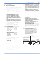
[Intrinsically Safe]
Hazardous Location
Class I, II, III, Division 1,
Groups A, B, C, D, E, F, G
Class 1, Zone 0 in
Hazardous (Classified)
Locations AEx ia IIC
Pressure Transmitters
+
Supply
–
Nonhazardous Location
Safety Barrier
+
+
–
–
General
Purpose
Equipment
+
–
F0203-1.ai
Entity Installation Requirements
Vmax ≥ Voc or Uo or Vt, Imax ≥ Isc or Io or It,
Pmax (or Po) ≤ Pi, Ca or Co ≥ Ci + Ccable,
La or Lo ≥ Li + Lcable
IM 01C25B01-01E
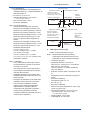
[Nonincendive]
Hazardous Location
Nonhazardous Location
Class I, II, Division 2,
Groups A, B, C, D, F, G
Class 1, Zone 2, Group IIC,
in Hazardous (Classified)
Locations
General
Purpose
Equipment
Pressure Transmitters
+
Supply
2-5
<2. Handling Cautions>
–
+
Not Use
Safety Barrier
–
F0203-2.ai
b. FM Explosionproof Type
Caution for FM explosionproof type.
Note 1. Model EJX/EJA-E Series pressure
transmitters with optional code /FF1 are
applicable for use in hazardous locations.
• Applicable Standard: FM3600, FM3615,
FM3810, ANSI/NEMA 250
• Explosionproof for Class I, Division 1,
Groups B, C and D.
• Dust-ignitionproof for Class II/III, Division 1,
Groups E, F and G.
• Enclosure rating: NEMA 4X.
• Temperature Class: T6
• Ambient Temperature: –40 to 60°C
• Supply Voltage: 42 V dc max.
• Output signal: 4 to 20 mA
Note 2. Wiring
• All wiring shall comply with National Electrical
Code ANSI/NFPA70 and Local Electrical
Codes.
• When installed in Division 1, “FACTORY
SEALED, CONDUIT SEAL NOT
REQUIRED.”
Note 3. Operation
• Keep the “WARNING” nameplate attached to
the transmitter.
WARNING: OPEN CIRCUIT BEFORE
REMOVING COVER. FACTORY SEALED,
CONDUIT SEAL NOT REQUIRED.
INSTALL IN ACCORDANCE WITH THE
USERS MANUAL IM 01C25.
• Take care not to generate mechanical
sparking when accessing to the instrument
and peripheral devices in a hazardous
location.
Note 4. Maintenance and Repair
• The instrument modification or parts
replacement by other than authorized
representative of Yokogawa Electric
Corporation is prohibited and will void
Factory Mutual Explosionproof Approval.
c. FM Intrinsically Safe Type/FM
Explosionproof Type
Model EJX/EJA-E Series pressure transmitters
with optional code /FU1 can be selected the
type of protection (FM Intrinsically Safe or FM
Explosionproof) for use in hazardous locations.
Note 1. For the installation of this transmitter,
once a particular type of protection is
selected, any other type of protection
cannot be used. The installation must be in
accordance with the description about the
type of protection in this instruction manual.
Note 2. In order to avoid confusion, unnecessary
marking is crossed out on the label other
than the selected type of protection when
the transmitter is installed.
2.9.2 CSA Certification
a. CSA Intrinsically Safe Type
Caution for CSA Intrinsically safe and
nonincendive type. (Following contents refer to
“DOC No. ICS013-A13”)
Note 1. Model EJX/EJA-E Series differential,
gauge, and absolute pressure transmitters
with optional code /CS1 are applicable for
use in hazardous locations
Certificate: 1606623
[For CSA C22.2]
• Applicable Standard: C22.2 No.0, C22.2
No.0.4, C22.2 No.25, C22.2 No.94, C22.2
No.157, C22.2 No.213, C22.2 No.61010-1
• Intrinsically Safe for Class I, Division 1,
Groups A, B, C & D, Class II, Division 1,
Groups E, F & G, Class III, Division 1
• Nonincendive for Class I, Division 2, Groups
A, B, C & D, Class II, Division 2, Groups E, F
& G, Class III, Division 1
• Enclosure: NEMA 4X
• Temp. Code: T4
• Amb. Temp.:–50* to 60°C
* –15°C when /HE is specified.
• Process Temperature: 120°C max.
IM 01C25B01-01E
[For CSA E60079]
• Applicable Standard: CAN/CSA E60079-0,
CAN/CSA E60079-11, CAN/CSA E60079-15,
IEC 60529:2001-02
• Ex ia IIC T4, Ex nL IIC T4
• Ambient Temperature: –50* to 60°C
* –15°C when /HE is specified.
• Max. Process Temp.: 120°C
• Enclosure: IP66/IP67
Note 2. Entity Parameters
• Intrinsically safe ratings are as follows:
Maximum Input Voltage (Vmax/Ui) = 30 V
Maximum Input Current (Imax/Ii) = 200 mA
Maximum Input Power (Pmax/Pi) = 0.9 W
Maximum Internal Capacitance (Ci) = 10 nF
Maximum Internal Inductance (Li) = 0 µH
• Type "n" or Nonincendive ratings are as
follows:
Maximum Input Voltage (Vmax/Ui) = 30 V
Maximum Internal Capacitance (Ci) = 10 nF
Maximum Internal Inductance (Li) = 0 µH
• Installation Requirements
Uo ≤ Ui, Io ≤ Ii, Po ≤ Pi,
Co ≥ Ci + Ccable, Lo ≥ Li + Lcable
Voc ≤ Vmax, Isc ≤ Imax,
Ca ≥ Ci + Ccable, La ≥ Li + Lcable
Uo, Io, Po, Co, Lo, Voc, Isc, Ca and La are
parameters of barrier.
Note 3. Installation
• In any safety barreir used output current
must be limited by a resistor 'R' such that
Io=Uo/R or Isc=Voc/R.
• The safety barrier must be CSA certified.
• Input voltage of the safety barrier must be
less than 250 Vrms/Vdc.
• Installation should be in accordance with
Canadian Electrical Code Part I and Local
Electrical Code.
• Dust-tight conduit seal must be used when
installed in Class II and III environments.
• The instrument modification or parts
replacement by other than authorized
representative of Yokogawa Electric
Corporation and Yokogawa Corporation
of America is prohibited and will void
Canadian Standards Intrinsically safe and
nonincendive Certification.
2-6
<2. Handling Cautions>
[Intrinsically Safe]
Hazardous Location
Nonhazardous Location
Group IIC, Zone 0
Class I, II, III, Division 1,
Groups A, B, C, D, E, F, G
Pressure Transmitters
+
Supply
–
General
Purpose
Equipment
+
Safety Barrier
+
+
–
–
–
F0204-1.ai
[Nonincendive]
Hazardous Location
Nonhazardous Location
Group IIC, Zone 2
Class I, II, Division 2,
Groups A, B, C, D, F, G
Class III, Division 1.
CSA Certified
Equipment
([nL] or
nonincendive)
Pressure Transmitters
+
Supply
–
+
–
Not Use
Safety Barrier
F0204-2.ai
b. CSA Explosionproof Type
Caution for CSA explosionproof type.
Note 1. Model EJX/EJA-E Series pressure
transmitters with optional code /CF1 are
applicable for use in hazardous locations:
• Certificate: 2014354
• Applicable Standard: C22.2 No.0,
C22.2 No.0.4, C22.2 No.0.5, C22.2 No.25,
C22.2 No.30, C22.2 No.94,
C22.2 No.61010-1-04, C22.2 No.60079-0,
C22.2 No.60079-1
• Explosion-proof for Class I, Groups B, C and
D.
• Dustignition-proof for Class II/III, Groups E, F
and G.
• Enclosure: NEMA 4X
• Temperature Code: T6...T4
• Ex d IIC T6...T4
• Enclosure: IP66/IP67
• Maximum Process Temperature: 120°C (T4),
100°C (T5), 85°C (T6)
• Ambient Temperature: –50* to 75°C (T4),
–50* to 80°C (T5), –50* to 75°C (T6)
* –15°C when /HE is specified.
• Supply Voltage: 42 V dc max.
• Output Signal: 4 to 20 mA dc
IM 01C25B01-01E
Note 2. Wiring
• All wiring shall comply with Canadian
Electrical Code Part I and Local Electrical
Codes.
• In hazardous location, wiring shall be in
conduit as shown in the figure.
• WARNING:
A SEAL SHALL BE INSTALLED WITHIN
50cm OF THE ENCLOSURE.
UN SCELLEMENT DOIT ÊTRE INSTALLÉ À
MOINS DE 50cm DU BOÎTIER.
• WARNING:
WHEN INSTALLED IN CL.I, DIV 2, SEAL
NOT REQUIRED.
UNE FOIS INSTALLÉ DANS CL I, DIV 2,
AUCUN JOINT N'EST REQUIS.
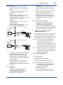
Non-Hazardous Hazardous Locations Division 1
Locations
Non-hazardous
Location
50 cm Max.
Equipment
E
SUP
PLY
Sealing Fitting
Conduit
CHECK
ALARM
Transmitter
F0205-1.ai
Non-Hazardous Hazardous Locations Division 2
Locations
PULS
E
Non-hazardous
Location
Equipment
42 V DC Max.
4 to 20 mA DC
Signal
• WARNING:
WHEN AMBIENT TEMPERATURE ≥ 65°C,
USE THE HEAT-RESISTING CABLES ≥
90°C.
QUAND LA TEMPÉRATURE AMBIANTE
≥ 65°C, UTILISEZ DES CÂBLES
RÉSISTANTES Á LA CHALEUR ≥ 90°C.
• Take care not to generate mechanical
sparking when accessing to the instrument
and peripheral devices in a hazardous
location.
Note 4. Maintenance and Repair
• The instrument modification or parts
replacement by other than authorized
representative of Yokogawa Electric
Corporation and Yokogawa Corporation of
America is prohibited and will void Canadian
Standards Explosionproof Certification.
c
PULS
42 V DC Max.
4 to 20 mA DC
Signal
2-7
<2. Handling Cautions>
SUP
CSA Intrinsically Safe Type/CSA
Explosionproof Type
Model EJX/EJA-E Series pressure transmitters
with optional code /CU1 can be selected the
type of protection (CSA Intrinsically Safe or CSA
Explosionproof) for use in hazardous locations.
Note 1. For the installation of this transmitter,
once a particular type of protection is
selected, any other type of protection
cannot be used. The installation must be in
accordance with the description about the
type of protection in this instruction manual.
PLY
CHECK
ALARM
Sealing Fitting
Transmitter
F0205-2.ai
• All wiring shall comply with local installation
requirements and local electrical code.
• In hazardous locations, the cable entry
devices shall be of a certified flameproof
type, suitable for the conditions of use and
correctly installed.
• Unused apertures shall be closed with
suitable flameproof certified blanking
elements. (The plug attached is flameproof
certified.)
Note 3. Operation
• WARNING:
AFTER DE-ENERGIZING, DELAY 5
MINUTES BEFORE OPENING.
APRÉS POWER-OFF, ATTENDRE 5
MINUTES AVANT D'OUVRIR.
Note 2. In order to avoid confusion, unnecessary
marking is crossed out on the label other
than the selected type of protection when
the transmitter is installed.
2.9.3 ATEX Certification
(1) Technical Data
a. ATEX Intrinsically Safe Type
Caution for ATEX Intrinsically safe type.
Note 1. Model EJX/EJA-E Series pressure
transmitters with optional code /KS21 for
potentially explosive atmospheres:
• No. DEKRA 11ATEX0228 X
• Applicable Standard:
EN 60079-0:2009, EN 60079-11:2007,
EN 60079-26:2007, EN 61241-11:2006
IM 01C25B01-01E
<2. Handling Cautions>
• Type of Protection and Marking code:
Ex ia IIC T4 Ga
Ex ia IIIC T85 ºC T100 ºC T120 ºC Db
• Group: II
• Category: 1G, 2D
• Ambient Temperature for EPL Ga:
–50 to 60°C
• Ambient Temperature for EPL Db:
–30* to 60°C
2-8
Note 5. Special Conditions for Safe Use
WARNING
* –15°C when /HE is specified.
• Process Temperature (Tp.): 120°C max.
• Maximum Surface Temperature for EPL Db:
T85°C (Tp.: 80°C)
T100°C (Tp.: 100°C)
T120°C (Tp.: 120°C)
• Enclosure: IP66 / IP67
Note 2 Electrical Data
• In type of explosion protection intrinsic safety
Ex ia IIC or Ex ia IIIC, only for connection to a
certified intrinsically safe circuit with following
maximum values:
Ui = 30 V
Ii = 200 mA
Pi = 0.9 W
(Linear Source)
Maximum internal capacitance; Ci = 27.6 nF
Maximum internal inductance; Li = 0 µH
Note 3. Installation
• Refer to the control drawing. All wiring shall
comply with local installation requirements.
• In the case where the enclosure of the
Pressure Transmitter is made of aluminium,
if it is mounted in an area where the use of
category 1 G apparatus is required, it must
be installed such, that, even in the event of
rare incidents, ignition sources due to impact
and friction sparks are excluded.
• Electrostatic charge may cause an exlosion
hazard. Avoid any actions that cause the
gerenation of eletrostatic charge, such as
rubbing with a dry cloth on coating face of
the product.
• In case of the enclosure of the Pressure
Transmitter with paint layers, if it is mounted
in an area where the use of category 2D
apparatus is required, it shall be installed in
such a way that the risk from electrostatic
discharges and propagating brush
discharges caused by rapid flow of dust is
avoided.
• To satisfy IP66 or IP67, apply waterproof
glands to the electrical connection port.
• When the lightning protector option is
specified, the apparatus is not capable
of withstanding the 500V insulation test
required by EN60079-11. This must be taken
into account when installing the apparatus.
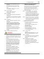
[Control Drawing]
Hazardous Location
Nonhazardous Location
Transmitter
Supply
+
+
–
–
Caution for ATEX flameproof type.
Safety Barrier *1
F0206.ai
b. ATEX Flameproof Type
*1: In any safety barriers used the output current must be
limited by a resistor “R” such that Io=Uz/R.
Note 4. Maintenance and Repair
• The instrument modification or parts
replacement by other than authorized
representative of Yokogawa Electric
Corporation is prohibited and will void
DEKRA Intrinsically safe Certification.
Note 1. Model EJX/EJA-E Series pressure
transmitters with optional code /KF22 for
potentially explosive atmospheres:
• No. KEMA 07ATEX0109 X
• Applicable Standard: EN 60079-0:2009,
EN 60079-1:2007, EN 60079-31:2009
• Type of Protection and Marking Code:
Ex d IIC T6...T4 Gb, Ex tb IIIC T85°C Db
• Group: II
• Category: 2G, 2D
• Enclosure: IP66 / IP67
• Temperature Class for gas-poof:
T6, T5, and T4
• Ambient Temperature for gas-proof:
–50 to 75°C (T6), –50 to 80°C (T5), and
–50 to 75°C (T4)
IM 01C25B01-01E
• Maximum Process Temperature (Tp.) for
gas-proof:
85°C (T6), 100°C (T5), and 120°C (T4)
• Maximum Surface Temperature for dustproof:
T85°C (Tamb.: –30* to 75°C, Tp.: 85°C)
* –15°C when /HE is specified.
Note 2. Electrical Data
• Supply voltage: 42 V dc max.
• Output signal: 4 to 20 mA
Note 3. Installation
• All wiring shall comply with local installation
requirement.
• The cable entry devices shall be of a certified
flameproof type, suitable for the conditions of
use.
Note 4. Operation
• Keep the “WARNING” label attached to the
transmitter.
WARNING: AFTER DE-ENERGIZING,
DELAY 5 MINUTES BEFORE OPENING.
WHEN THE AMBIENT TEMP.≥65°C, USE
HEAT-RESISTING CABLE AND CABLE
GLAND ≥90°C.
• Take care not to generate mechanical
sparking when accessing to the instrument
and peripheral devices in a hazardous
location.
Note 5. Special Conditions for Safe Use
WARNING
• Electrostatic charge may cause an exlosion
hazard. Avoid any actions that cause the
gerenation of eletrostatic charge, such as
rubbing with a dry cloth on coating face of the
product.
• In the case where the enclosure of the
Pressure Transmitter is made of aluminium,
if it is mounted in an area where the use of
category 2D apparatus is required, it shall
be installed in such a way that the risk from
electrostatic discharges and propagating
brush discharges caused by rapid flow of
dust is avoided.
• The instrument modification or parts
replacement by other than an authorized
Representative of Yokogawa Electric
Corporation is prohibited and will void the
certification.
• To satisfy IP66 or IP67, apply waterproof
glands to the electrical connection port.
2-9
<2. Handling Cautions>
c. ATEX Intrinsically Safe Type/ATEX
Flameproof Type/ATEX Type n
Model EJX/EJA-E Series pressure transmitters
with optional code /KU22 can be selected
the type of protection ATEX Intrinsically
Safe, Flameproof or ATEX Type n for use in
hazardous locations.
Note 1. For the installation of this transmitter,
once a particular type of protection is
selected, any other type of protection
cannot be used. The installation must be in
accordance with the description about the
type of protection in this user’s manual.
Note 2. In order to avoid confusion, unnecessary
marking is crossed out on the label other
than the selected type of protection when
the transmitter is installed.
● ATEX Type of Protection “n”
• Applicable Standard: EN 60079-0:2009,
EN 60079-15:2005
• Type of Protection and Marking Code:
Ex nL IIC T4 Gc
• Temperature Class: T4
• Enclosure: IP66/IP67
• Process Temperature: 120°C max.
• Ambient Temperature: –30* to 60°C
* –15°C when /HE is specified.
Note 1. Electrical Data
Ui = 30 V
Maximum internal capacitance; Ci = 10 nF
Maximum internal inductance; Li = 0 µH
Note 2. Installation
• All wiring shall comply with local installation
requirements. (refer to the installation
diagram)
Note 3. Maintenance and Repair
• The instrument modification or parts
replacement by other than authorized
representative of Yokogawa Electric
Corporation is prohibited and will void Type
of Protection “n”.
IM 01C25B01-01E
<2. Handling Cautions>
(3) Installation
[Installation Diagram]
Hazardous Location
(Zone 2 only)
Transmitter
Supply
+
–
Nonhazardous Location
+
Associated
– Apparatus
F0207.ai
Ratings of the Power Supply as follows;
Maximum Voltage: 30 V
• Electrostatic charge may cause an exlosion
hazard. Avoid any actions that cause the
gerenation of eletrostatic charge, such as
rubbing with a dry cloth on coating face of
the product.
(2) Electrical Connection
• OPEN CIRCUIT BEFORE REMOVING
COVER. INSTALL IN ACCORDANCE WITH
THIS USER’S MANUAL
• Take care not to generate mechanical
sparking when access to the instrument and
peripheral devices in a hazardous location.
(5) Maintenance and Repair
A mark indicating the electrical connection type
is stamped near the electrical connection port.
These marks are as followed.
ANSI 1/2 NPT female
• All wiring shall comply with local installation
requirements and the local electrical code.
• There is no need for conduit seal in Division
1 and Division 2 hazardous locations
because this product is sealed at the factory.
WARNING
WARNING
ISO M20 × 1.5 female
WARNING
(4) Operation
Note 4. Special Conditions for Safe Use
Screw Size
2-10
Marking
M
N or
W
WARNING
The instrument modification or parts replacement
by other than an authorized Representative of
Yokogawa Electric Corporation is prohibited and
will void the certification.
Location of the mark
F0208.ai
IM 01C25B01-01E
2.9.4 IECEx Certification
(6) Name Plate
Model EJX Series pressure transmitters with
optional code /SU2 can be selected the type of
protection (IECEx Intrinsically Safe/type n or
flameproof) for use in hazardous locations.
Name plate
Tag plate for flameproof type
No. KEMA 07ATEX0109 X
Ex d IIC T6...T4 Gb, Ex tb IIIC T85°C Db
Enlcosure : IP66/IP67
TEMP. CLASS
T6 T5
T4
MAX PROCESS TEMP.(Tp.)
85 100 120 °C
Tamb.
-50 to 75
80
75 °C
T85°C(Tamb.:-30(-15) to 75°C, Tp.:85°C)(for Dust)
D
WARNING
AFTER DE-ENERGIZING, DELAY 5 MINUTES BEFORE
OPENING.
WHEN THE AMBIENT TEMP. ≥ 65°C, USE THE
HEAT-RESISTING CABLE & CABLE GLAND ≥ 90°C
POTENTIAL ELECTROSTATIC CHARGING HAZARD
Tag plate for intrinsically safe type
No. DEKRA 11ATEX 0228 X
Ex ia IIC T4 Ga Ta: -50 TO 60°C
Ex ia IIIC T85°C T100°C T120°C Db Ta:-30(-15) TO 60°C
IP66/IP67
MAX. PROCESS TEMP.(Tp.) 120°C
T85°C(Tp.:80°C), T100°C(Tp.:100°C), T120°C(Tp.:120°C)
Ui=30V, Ii=200mA , Pi=0.9W, Ci=27.6nF, Li=0µH
D
WARNING
POTENTIAL ELECTROSTATIC
CHARGING HAZARD
- SEE USER’S MANUAL
Tag plate for type n protection
Ex nLIIC T4 Gc
IP66/IP67
Tamb. -30(-15) to 60°C
MAX. PROCESS TEMP.(Tp.)
Ui=30V, Ci=10nF, Li=0µH
120°C
WARNING
POTENTIAL ELECTROSTATIC
CHARGING HAZARD
- SEE USER’S MANUAL
F0209.ai
MODEL: Specified model code.
STYLE: Style code.
SUFFIX: Specified suffix code.
SUPPLY: Supply voltage.
OUTPUT: Output signal.
MWP: Maximum working pressure.
CAL RNG: Specified calibration range.
NO.: Serial number and year of production*1.
TOKYO 180-8750 JAPAN:
The manufacturer name and the address*2.
2-11
<2. Handling Cautions>
*1: The first digit in the three numbers next to the nine
letters of the serial number appearing after “NO.”
on the nameplate indicates the year of production.
The following is an example of a serial number for a
product that was produced in 2010:
91K819857
032
Note 1. For the installation of this transmitter,
once a particular type of protection is
selected, any other type of protection
cannot be used. The installation must be in
accordance with the description about the
type of protection in this instruction manual.
Note 2. In order to avoid confusion, unnecessary
marking is crossed out on the label other
than the selected type of protection when
the transmitter is installed.
a. IECEx Intrinsically Safe Type / type n
Caution for IECEx Intrinsically safe and type n.
Note 1. Model EJX Series differential, gauge,
and absolute pressure transmitters with
optional code /SU2 are applicable for use
in hazardous locations
• No. IECEx CSA 05.0005
• Applicable Standard: IEC 60079-0:2000,
IEC 60079-11:1999, IEC 60079-15:2001
• Ex ia IIC T4, Ex nL IIC T4
• Ambient Temperature: –50 to 60°C
• Max. Process Temp.: 120°C
• Enclosure: IP66/IP67
Note 2. Entity Parameters
• Intrinsically safe ratings are as follows:
Maximum Input Voltage (Vmax/Ui) = 30 V
Maximum Input Current (Imax/Ii) = 200 mA
Maximum Input Power (Pmax/Pi) = 0.9 W
Maximum Internal Capacitance (Ci) = 10 nF
Maximum Internal Inductance (Li) = 0 µH
• Type "n" ratings are as follows:
Maximum Input Voltage (Vmax/Ui) = 30 V
Maximum Internal Capacitance (Ci) = 10 nF
Maximum Internal Inductance (Li) = 0 µH
• Installation Requirements
Uo ≤ Ui, Io ≤ Ii, Po ≤ Pi,
Co ≥ Ci + Ccable, Lo ≥ Li + Lcable
Voc ≤ Vmax, Isc ≤ Imax,
Ca ≥ Ci + Ccable, La ≥ Li + Lcable
Uo, Io, Po, Co, Lo, Voc, Isc, Ca and La are
parameters of barrier.
The year 2010
*2: “180-8750” is a zip code which represents the following address.
2-9-32 Nakacho, Musashino-shi, Tokyo Japan
IM 01C25B01-01E
<2. Handling Cautions>
Note 3. Installation
• In any safety barrier used output current
must be limited by a resistor 'R' such that
Io=Uo/R.
• The safety barrier must be IECEx certified.
• Input voltage of the safety barrier must be
less than 250 Vrms/Vdc.
• The instrument modification or parts
replacement by other than authorized
representative of Yokogawa Electric
Corporation and will void IECEx Intrinsically
safe and type n certification.
[Intrinsically Safe]
Hazardous Location
Nonhazardous Location
Group IIC, Zone 0
IECEx certified
Safety Barrier
+
+
Pressure Transmitters
+
Supply
–
–
–
General
Purpose
Equipment
+
–
F0210-1.ai
[type n]
Hazardous Location
Nonhazardous Location
Group IIC, Zone 2
IECEx Certified
Equipment [nL]
Pressure Transmitters
+
Supply
–
+
Not Use
Safety Barrier
–
F0210-2.ai
b. IECEx Flameproof Type
Caution for IECEx flameproof type.
Note 1. Model EJX/EJA-E Series pressure
transmitters with optional code /SF2 or /
SU2 are applicable for use in hazardous
locations:
• No. IECEx CSA 07.0008
• Applicable Standard: IEC60079-0:2004,
IEC60079-1:2003
• Flameproof for Zone 1, Ex d IIC T6...T4
• Enclosure: IP66/IP67
• Maximum Process Temperature: 120°C (T4),
100°C (T5), 85°C (T6)
• Ambient Temperature: –50 to 75°C (T4),
–50 to 80°C (T5), –50 to 75°C (T6)
• Supply Voltage: 42 V dc max.
• Output Signal: 4 to 20 mA dc
2-12
Note 2. Wiring
• In hazardous locations, the cable entry
devices shall be of a certified flameproof
type, suitable for the conditions of use and
correctly installed.
• Unused apertures shall be closed with
suitable flameproof certified blanking
elements.
Note 3. Operation
• WARNING:
AFTER DE-ENERGIZING, DELAY 5
MINUTES BEFORE OPENING.
• WARNING:
WHEN AMBIENT TEMPERATURE ≥ 65°C,
USE THE HEAT-RESISTING CABLES ≥
90°C.
• Take care not to generate mechanical
sparking when accessing to the instrument
and peripheral devices in a hazardous
location.
Note 4. Maintenance and Repair
• The instrument modification or parts
replacement by other than authorized
representative of Yokogawa Electric
Corporation is prohibited and will void IECEx
Certification.
2.10 EMC Conformity Standards
EN61326-1 Class A, Table2 (For use in industrial
locations)
EN61326-2-3
CAUTION
To meet EMC regulations, Yokogawa
recommends that customers run signal wiring
through metal conduits or use shielded twistedpair cabling when installing EJX/EJA-E series
transmitters in a plant.
2.11 Pressure Equipment
Directive (PED)
(1) General
• EJX/EJA-E Series pressure transmitters are
categorized as piping under the pressure
accessories section of directive 97/23/EC,
which corresponds to Article 3, Paragraph 3 of
PED, denoted as Sound Engineering Practice
(SEP).
IM 01C25B01-01E
• EJX110A-MS, EJX110A-HS,
EJX110A-VS, EJ130, EJ440,
EJ510-D, EJ530-D, EJX610A-D,
and EJX630A-D can be used above 200
bar and therefore considered as a part of a
pressure retaining vessel where category III,
Module H applies. These models with option
code /PE3 conform to that category.
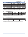
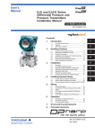
(2) Technical Data
• Models without /PE3
Article 3, Paragraph 3 of PED, denoted as
Sound Engineering Practice (SEP).
• Models with /PE3
Module: H
Type of Equipment: Pressure Accessory-Vessel
Type of fluid: Liquid and Gas
Group of fluid: 1 and 2
Model
Capsule
code
EJA110E
M, H, V
EJ110
F, L
PS*1
(bar)
V(L)
PS.V
(bar.L)
160
0.01
1.6
Category*2
Article 3,
Paragraph 3
(SEP)
EJX110A
M, H, V
250
0.01
2.5
EJX110A
with code
/PE3
M, H, V
250
0.01
2.5
III
EJ130
M, H
500
0.01
5.0
Article 3,
Paragraph 3
(SEP)
EJ130
with code
/PE3
M, H
500
0.01
5.0
III
EJ310 L, M, A, B
160
0.01
1.6
Article 3,
Paragraph 3
(SEP)
Article 3,
Paragraph 3
(SEP)
Article 3,
Paragraph 3
(SEP)
EJ430
H, A, B
160
0.01
1.6
EJ440
C, D
500
0.1
5.0
EJ440
with code
/PE3
C, D
500
0.1
5.0
III
A, B, C
100
0.1
10
D
700
0.1
70
Article 3,
Paragraph 3
(SEP)
D
700
0.1
70
III
A, B, C
100
0.1
10
D
700
0.1
70
Article 3,
Paragraph 3
(SEP)
D
700
0.1
70
III
EJ510
EJX610A
EJ510,
EJX610A
with code /
PE3
EJ530,
EJX630A
EJ530,
EJX630A
with code
/PE3
2-13
<2. Handling Cautions>
*1: PS is maximum pressure for vessel itself based on
Pressure Equipment Directive 97/23/EC. Refer to
General Specification for maximum working pressure of a
transmitter.
*2: Referred to Table 1 covered by ANNEX II of EC Directive
on Pressure Equipment Directive 97/23/EC
(3) Operation
CAUTION
• The temperature and pressure of fluid should
be maintained at levels that are consistent
with normal operating conditions.
• The ambient temperature should be
maintained at a level that is consistent with
normal operating conditions.
• Please take care to prevent water hammer
and the like from inducing excessive
pressures in pipes and valves. If phenomena
are likely, install a safety valve or take
some other appropriate measure to prevent
pressure from exceeding PS.
• Take appropriate measures at the device or
system level to protect transmitters if they
are to be operated near an external heat
source.
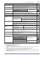
2.12 Low Voltage Directive
Applicable standard: EN61010-1
(1) Pollution Degree 2
"Pollution degree" describes the degree to
which a solid, liquid, or gas which deteriorates
dielectric strength or surface resistivity is
adhering. " 2 " applies to normal indoor
atmosphere. Normally, only non-conductive
pollution occurs. Occasionally, however,
temporary conductivity caused by condensation
must be expected.
(2) Installation Category I
"Overvoltage category (Installation category)"
describes a number which defines a transient
overvoltage condition. It implies the regulation
for impulse withstand voltage. " I " applies to
electrical equipment which is supplied from the
circuit when appropriate transient overvoltage
control means (interfaces) are provided.
IM 01C25B01-01E
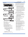
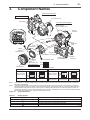
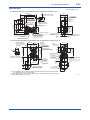
3-1
<3. Component Names>
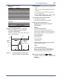
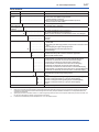
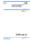
3.
Component Names
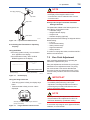
Vertical impulse piping type
Pressure-detector section
Terminal box cover
Cover flange
Horizontal impulse piping type
External indicator
conduit connection (Note 1)
Conduit
connection
Zeroadjustment
screw
(Note 2)
Slide switch
Integral
indicator (Note 1)
Mounting screw
Vent plug
CPU assembly
Amplifier Cover
Drain plug
Burnout direction switch
Range-setting
switch (Note 1)
(See section 7.6)
BO H
L
Transmitter section
WR E
D
Process
connector (Note 1)
Process
connection
Write protection switch
Burnout direction switch (BO)
Burnout Direction
Switch Position
H
Burnout Direction
L
HIGH
Hardware write protection switch (WR)
H
L
LOW
Write Protection
Switch Position
H
L
H
L
E
D
E
D
Write Protection
NO
(Write enabled)
YES
(Write disabled)
F0301.ai
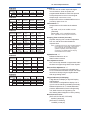
Note 1: See subsection 9.2, “Model and Suffix Codes,” for details. A process connector will not be applied for lower side of EJ310,
EJ430, and EJ440.
Note 2: Applicable for BRAIN/HART communication type. Set the switches as shown in the figure above to set the burn-out direction
and write protection. The Burnout switch is set to the H side for delivery (unless option code /C1 or /C2 is specified in the order),
and the hardware write protection switch is set to E side. The setting of the switches can be confirmed via communication. An
external zero adjustment screw can only be disabled by communication. To disable the screw, set a parameter before activating
the hardware write protect function. See each communication manual.
Figure 3.1
Component Names
Table 3.1
Display Symbol
Display Symbol
Meaning of Display Symbol
Display mode is ‘square root’. (Display is not lit when ‘linear’ mode.)
The output signal being zero-adjusted is increasing.
The output signal being zero-adjusted is decreasing.
Write protect function is enabled.
F0302.ai
IM 01C25B01-01E
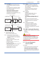
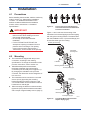
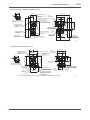
4.
4-1
<4. Installation>
Installation
4.1 Precautions
Before installing the transmitter, read the cautionary
notes in section 2.4, “Selecting the Installation
Location.” For additional information on the
ambient conditions allowed at the installation
location, refer to subsection 9.1 “Standard
Specifications.”
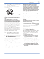
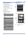
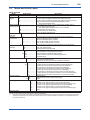
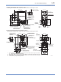
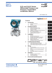
57 mm
51 mm
F0401.ai
Figure 4.1
IMPORTANT
• When welding piping during construction,
take care not to allow welding currents to
flow through the transmitter.
• Do not step on this instrument after
installation.
• For the EJ430 and EJ440, the
atmospheric opening is located on the low
pressure side cover flange. The opening
must not face upward. See section 9.4,
“Dimensions,” for the location of the opening.
54 mm
Process Connector Impulse Piping
Connection Distances for Differential
Pressure Transmitters
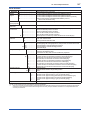
Figure 4.1 and 4.2 shows the mounting of the
transmitter for horizontal piping and vertical piping
with using the mounting bracket. The transmitters
with the installation code -U (Universal flange) can
be used for either type of mounting.
Vertical pipe mounting
Transmitter
mounting bolt
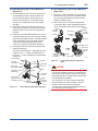
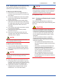
4.2 Mounting
■ The transmitter is shipped with the process
connection, according to the ordering
specifications. To change the orientation of the
process connections, refer to section 4.3.
■ With differential pressure transmitters,
the distance between the impulse piping
connection ports is usually 54 mm (figure 4.1).
By changing the orientation of the process
connector, the dimension can be changed to 51
mm or 57 mm.
■ The transmitter can be mounted on a nominal
50 mm (2-inch) pipe using the mounting
bracket supplied, as shown in figure 4.2 and
4.3 The transmitter can be mounted on either a
horizontal or a vertical pipe.
■ When mounting the bracket on the transmitter,
tighten the (four) bolts that hold the transmitter
with a torque of approximately 39 N·m {4kgf·m}.
U-bolt nut
Mounting bracket
U-bolt
50 mm(2-inch) pipe
Horizontal pipe mounting
Transmitter
mounting bolt
U-bolt nut
Mounting bracket
U-bolt
50 mm(2-inch) pipe
Figure 4.2
F0402.ai
Transmitter Mounting (Horizontal
Impulse Piping Type)
IM 01C25B01-01E
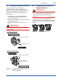
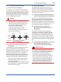
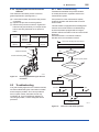
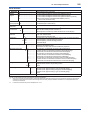
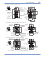
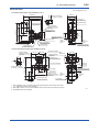
4.3 Changing the Process
Connection
Vertical pipe mounting
(Process connector downside)
Transmitter
mounting bolt
Mounting bracket
50 mm(2-inch) pipe
U-bolt nut
U-bolt
Vertical pipe mounting
(Process connector upside)
The transmitter is shipped with the process
connection specified at the time of ordering. To
change the process connection, the drain (vent)
plug must be repositioned.
To reposition a drain (vent) plug, use a wrench to
slowly and gently unscrew it. Then, remove and
remount it on the opposite side. Wrap sealing tape
around the drain (vent) plug threads (*1 in the figure
below), and apply a lubricant to the threads of the
drain (vent) screw(s) (*2 below). To tighten the drain
(vent) plugs, apply a torque of 34 to 39 N·m (3.5 to 4
kgf·m). Process connector bolts are to be tightened
uniformly to a torque shown in table 4.1.
Table 4.1
50 mm(2-inch) pipe
U-bolt nut
U-bolt
Transmitter
mounting bolt
Torque
EJ110
EJ120
EJ130
EJ310
EJ430
Model
Mounting bracket
Figure 4.3
4-2
<4. Installation>
Torque(N·m)
{kgf·m}
EJ440
C capsule
39 to 49 {4 to 5}
Vertical impulse piping type
D capsule
49 to 59
{5 to 6}
Horizontal impulse piping type
Bolt
F0403.ai
Transmitter Mounting (Vertical Impulse
Piping Type)
Process
connector
gasket
*1
Drain/vent plug
*2
Note: For a horizontal impulse
piping type, moving the
process connectors from
the front side to the
back cannot be made.
F0404.ai
Figure 4.4
Changing Process Connection
IM 01C25B01-01E
4-3
<4. Installation>
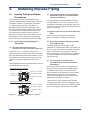
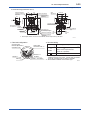
4.4 Swapping the High/Lowpressure Side Connection
IMPORTANT
This section is applicable only for EJ110,
EJ120, and EJ130 differential
transmitters, and not applicable for gauge or
absolute pressure transmitters.
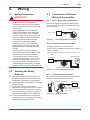
4.4.1 Rotating Pressure-detector Section
180°
This procedure can be applied only to a transmitter
with a vertical impulse piping type.
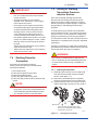
4.4.2 Using the Communicator
This method is applicable only to the Model
EJ110, EJ120, and EJ130.
With a communicator, you can change which
process connection is used as the high-pressure
side without mechanically rotating the pressuredetector section 180 as described in subsection
4.4.1. To change, call parameter ‘D15: H/L SWAP’
for BRAIN Communication or ‘H/L swap’ for HART
Communication and select REVERSE (right side:
low pressure; left side: high pressure) or select
NORMAL to change back to normal (right side: high
pressure; left side: low pressure).
NORMAL
The procedure below can be used to turn the
pressure detector assembly 180°. Perform
this operation in a maintenance shop with the
necessary tools laid out and ready for use, and then
install the transmitter in the field after making the
change.
1)Use an Allen wrench (JIS B4648, nominal 2.5
mm) to remove the two setscrews at the joint
between the pressure-detector section and
transmitter section.
2)Leaving the transmitter section in position,
rotate the pressure-detector section 180°.
3)Tighten the two setscrews to fix the pressuredetector section and transmitter section
together (at a torque of 1.5 N·m).
Reposition the process connector and drain
(vent) plugs to the opposite side as described in
subsection 4.3.
Process connector
Output
Input
REVERSE
Figure 4.6
F0406.ai
Input/Output Relationship
IMPORTANT
Since the H/L label plate on the capsule
assembly will remain unchanged, use this
function only when you cannot switch the
impulse piping. If the ‘H/L SWAP’ parameter
setting is changed, the input/output relationship
is reversed as shown in figure 4.6; be sure this is
understood by all.
Setscrew
Before
After rotating 180°
F0405.ai
Figure 4.5
Before and After Modification
IM 01C25B01-01E
4-4
<4. Installation>
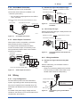
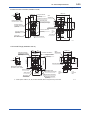
4.5 Rotating Transmitter Section
The transmitter section can be rotated
approximately 360° (180° to either direction or
360° to one direction from the original position at
shipment, depending on the configuration of the
instrument.) It can be fixed at any angle within
above range.
1)Remove the two setscrews that fasten the
transmitter section and capsule assembly,
using the Allen wrench.
2)Rotate the transmitter section slowly and stop it
at designated position.
3)Tighten the two setscrews to a torque of 1.5
N·m.
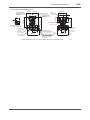
4.6 Changing the Direction of
Integral Indicator
IMPORTANT
Always turn OFF power, release pressure and
remove a transmitter to non-hazardous area
before disassembling and reassmbling an
indicator.
An integral indicator can be installed in the
following three directions. Follow the instructions in
section 8.4 for removing and attaching the integral
indicator.
IMPORTANT
Do not rotate the transmitter section more than
the above limit.
F0408.ai
Figure 4.8
Vertical impulse piping type
Integral Indicator Direction
Pressure-detector section
Stopper
Rotate 0 to ±180° segments
Conduit connection
Transmitter section
Horizontal impulse piping type
Transmitter section
Rotate 0 to ±180° segments
Conduit connection
Zero-adjustment screw
Pressure-detector section
F0407.ai
Figure 4.7
Rotating Transmitter Section (Left Side
High Pressure Type)
IM 01C25B01-01E
5.
5-1
<5. Installing Impulse Piping>
Installing Impulse Piping
5.1 Impulse Piping Installation
Precautions
(2) Changing the Process Connector Piping
Connections (Figure 4.1) (for differential
pressure transmitters)
The impulse piping that connects the process
outputs to the transmitter must convey the process
pressure accurately. If, for example, gas collects
in a liquid-filled impulse line, or the drain for a
gas-filled impulse line becomes plugged, it will
not convey the pressure accurately. Since this will
cause errors in the measurement output, select
the proper piping method for the process fluid
(gas, liquid, or steam). Pay careful attention to the
following points when routing the impulse piping
and connecting the impulse piping to a transmitter.
The impulse piping connection distances can be
changed between 51 mm, 54 mm and 57 mm by
changing the orientation of the process connectors.
This is convenient for aligning an impulse line with a
process connectors.
5.1.1 Connecting Impulse Piping to a
Transmitter
(4) Removing the Impulse Piping Connecting
Port Dustproof Cap
(1) Check the High and Low Pressure
Connections on the Transmitter (Figure 5.1)
Symbols “H” and “L” have been placed on the
capsule assembly to indicate high and low pressure
side. With differential pressure transmitters, connect
the high pressure side impulse line to the “H” side,
and the low pressure side impulse line to the “L”
side.
With gauge/absolute pressure transmitters, connect
the impulse line to the ‘H’ side.
Differential Pressure Transmitter
“H” and “L” are shown
Process connection
Pressure
connection
Process connector
Bolt
Gauge/Absolute Pressure Transmitters
“H” and “L” are shown
Process connection
(3) Tightening the Process Connector Mounting
Bolts
After connecting an impulse line, tighten the
process connector mounting bolts uniformly.
The impulse piping connecting port on the
transmitter is covered with a plastic cap to keep out
dust. This cap must be removed before connecting
the line. (Be careful not to damage the threads
when removing this cap. Never insert a screwdriver
or other tool between the cap and port threads to
remove the cap.)
(5) Connecting the Transmitter and 3Valve Manifold (for differential pressure
transmitters)
A 3-valve manifold consists of two stop valves to
block process pressure and an equalizing valve
to equalize the pressures on the high and low
pressure sides of the transmitter. Such a manifold
makes it easier to disconnect the transmitter
from the impulse piping, and is convenient when
adjusting the transmitter zero point.
There are two 3-valve manifold types: the pipemounting type and the direct-mounting type; care
should be taken with respect to the following points
when connecting the manifold to the transmitter.
Process connector
Bolt
Figure 5.1
F0501.ai
“H” and “L” Symbols on a Capsule
Assembly
IM 01C25B01-01E
5-2
<5. Installing Impulse Piping>
Pipe-Mounting Type 3-Valve Manifold
(Figure 5.2)
Direct-Mounting Type 3-Valve Manifold
(Figure 5.3)
1) Screw nipples into the connection ports on the
transmitter side of the 3-valve manifold, and
into the impulse piping connecting ports on
the process connectors. (To maintain proper
sealing, wind sealing tape around the nipple
threads.)
2) Mount the 3-valve manifold on the 50 mm (2inch) pipe by fastening a U-bolt to its mounting
bracket. Tighten the U-bolt nuts only lightly at
this time.
3) Install the pipe assemblies between the 3-valve
manifold and the process connectors and lightly
tighten the ball head lock nuts. (The ball-shaped
ends of the pipes must be handled carefully,
since they will not seal properly if the ball
surface is scratched or otherwise damaged.)
4) Now tighten the nuts and bolts securely in the
following sequence:
Process connector bolts → transmitter-end ball
head lock nuts → 3-valve manifold ball head
lock nuts → 3-valve manifold mounting bracket
U-bolt nuts
1) Mount the 3-valve manifold on the transmitter.
(When mounting, use the two gaskets and the
four bolts provided with the 3-valve manifold.
Tighten the bolts evenly.)
2) Mount the process connectors and gaskets
on the top of the 3-valve manifold (the side on
which the impulse piping will be connected).
Impulse piping
Vent plug
(optional)
Nipple
3-valve
manifold
Stop valve
(low pressure side)
Equalizing valve
(balancing)
Pipes
Pipe
Ball head
lock nut
Stop valve
(high pressure side)
50 mm(2-inch) pipe
Ball head
lock nut
Nipple
Process
connector bolts
Process
connector
F0502.ai
Figure 5.2
3-Valve Manifold (Pipe-Mounting Type)
Impulse
piping
Bolts
Process
connector
Stop valve
Gasket
3-valve
manifold
Equalizing
valve
Stop valve
Equalizing valve
Stop valve
Impulse
piping
Bolts
Gasket
Process
connector
Figure 5.3
Stop valve
3-valve
manifold
F0503.ai
3-Valve Manifold (Direct-Mounting
Type)
NOTE
After completing the connection of the transmitter
and 3-valve manifold, be sure to CLOSE the low
pressure and high pressure stop valves, OPEN
the equalizing valve, and leave the manifold with
the equalizing valve OPEN.
You must do this in order to avoid overloading
the transmitter from either the high or the low
pressure side when beginning operation.
This instruction must also be followed as part of
the startup procedure (chapter 7.)
IM 01C25B01-01E
5.1.2 Routing the Impulse Piping
(3) Impulse Piping Slope
(1) Process Pressure Tap Angles
If condensate, gas, sediment or other extraneous
material in the process piping gets into the impulse
piping, pressure measurement errors may result. To
prevent such problems, the process pressure taps
must be angled as shown in figure 5.4 according to
the kind of fluid being measured.
NOTE
• If the process fluid is a gas, the taps must be
vertical or within 45° either side of vertical.
• If the process fluid is a liquid, the taps must
be horizontal or below horizontal, but not
more than 45° below horizontal.
• If the process fluid is steam or other
condensing vapor, the taps must be
horizontal or above horizontal, but not more
than 45° above horizontal.
[Gas]
Pressure
taps
Process
piping
[Liquid]
[Steam]
45° 45°
45°
45°
45°
45°
F0504.ai
Figure 5.4
5-3
<5. Installing Impulse Piping>
Process Pressure Tap Angle
(For Horizontal Piping)
(2) Position of Process Pressure Taps and
Transmitter
If condensate (or gas) accumulates in the impulse
piping, it should be removed periodically by
opening the drain (or vent) plugs. However, this will
generate a transient disturbance in the pressure
measurement, and therefore it is necessary to
position the taps and route the impulse piping so
that any extraneous liquid or gas generated in the
leadlines returns naturally to the process piping.
• If the process fluid is a gas, then as a rule the
transmitter must be located higher than the
process pressure taps.
• If the process fluid is a liquid or steam, then as a
rule the transmitter must be located lower than
the process pressure taps.
The impulse piping must be routed with only an
upward or downward slope. Even for horizontal
routing, the impulse piping should have a slope of
at least 1/10 to prevent condensate (or gases) from
accumulating in the pipes.
(4) Temperature Difference Between Impulse
Lines (for differential pressure transmitters)
If there is a temperature difference between the
high and low impulse lines, the density difference
of the fluids in the two lines will cause an error in
the measurement pressure. When measuring flow,
impulse lines must be routed together so that there
is no temperature difference between them.
(5) Condensate Pots for Steam Flow
Measurement (for differential pressure
transmitters)
If the liquid in the impulse piping repeatedly
condenses or vaporizes as a result of changes
in the ambient or process temperature, this will
cause a difference in the fluid head between the
high pressure and low pressure sides. To prevent
measurement errors due to these head differences,
condensate pots are used when measuring steam
flow.
(6) Preventing Wind Speed Effects in Very Low
Differential Pressure Measurement
(for differential pressure transmitters)
IMPORTANT
When using a differential pressure transmitter
to measure very low pressures (draft pressure),
the low pressure connection port is left open
to atmospheric pressure (the reference
pressure). Any wind around the differential
pressure transmitter will therefore cause errors
in the measurement. To prevent this, it will be
necessary either to enclose the transmitter in
a box, or to connect an impulse line to the low
pressure side and insert its end into a windexcluding pot (cylindrical with a base plate).
IM 01C25B01-01E
(7) Preventing Freezing
If there is any risk that the process fluid in the
impulse piping or transmitter could freeze, use a
steam jacket or heater to maintain the temperature
of the fluid.
NOTE
After completing the connections, close the
valves on the process pressure taps (main
valves), the valves at the transmitter (stop
valves), and the impulse piping drain valves,
so that condensate, sediment, dust and other
extraneous material cannot enter the impulse
piping.
5.2 Impulse Piping Connection
Examples
Figure 5.5 and 5.6 show examples of typical
impulse piping connections. Before connecting the
transmitter to the process, study the transmitter
installation location, the process piping layout,
and the characteristics of the process fluid
(corrosiveness, toxicity, flammability, etc.), in order
to make appropriate changes and additions to the
connection configurations.
Liguid
Gas
Orifice
Tap
valve
Steam
Condensate pot
Union
or flange
Tee
3-valve
manifold
Drain
valve
Drain
plug
F0505.ai
Figure 5.5
Impulse Piping Connection Examples
for Differential Pressure Transmitters
Liquid
Gas
Steam
Union or flange
Tap valve
Union or flange
Drain plug
Drain valve
Union or
flange
Tee
Note the following points when referring to these
piping examples.
• The high pressure connecting port on the
transmitter is shown on the right (as viewed
from the front).
• The transmitter impulse piping connection is
shown for a vertical impulse piping connection
configuration in which the direction of
connection is either upwards or downwards.
• If the impulse line is long, bracing or supports
should be provided to prevent vibration.
• The impulse piping material used must
be compatible with the process pressure,
temperature, and other conditions.
• A variety of process pressure tap valves (main
valves) are available according to the type
of connection (flanged, screwed, welded),
construction (globe, gate, or ball valve),
temperature and pressure. Select the type of
valve most appropriate for the application.
5-4
<5. Installing Impulse Piping>
Tee
Tap valve
Tee
Union or flange
Tap valve
Drain valve
Drain valve
Drain plug
Drain plug
F0506.ai
Figure 5.6
Impulse Piping Connection Examples
for Gauge/absolute Pressure
Transmitters
IM 01C25B01-01E
Wiring
IMPORTANT
• Lay wiring as far as possible from electrical
noise sources such as large capacity
transformers, motors, and power supplies.
• Remove the electrical connection dust cap
before wiring.
• All threaded parts must be treated with
waterproofing sealant. (A non-hardening
silicone group sealant is recommended.)
• To prevent noise pickup, do not pass signal
and power cables through the same ducts.
• Explosion-protected instruments must
be wired in accordance with specific
requirements (and, in certain countries,
legal regulations) in order to preserve the
effectiveness of their explosion-protected
features.
• The terminal box cover is locked by an
Allen head bolt (a shrouding bolt) on ATEX
flameproof type transmitters. When the
shrouding bolt is driven clockwise using
an Allen wrench, it goes in. The cover lock
can then be released and the cover can
be opened by hand. See subsection 8.4
“Disassembly and Reassembly” for details.
• Plug and seal an unused conduit connection.
6.3 Connections of External
Wiring to Terminal Box
6.3.1 Power Supply Wiring Connection
Connect the power supply wiring to the SUPPLY +
and – terminals. When /AL is specified, also refer to
subsection 6.3.5.
Transmitter terminal box
+
Power supply
–
PULSE
6.1 Wiring Precautions
SUPP
LY
CHECKM
ALAR
F0601.ai
Figure 6.1
Power Supply Wiring Connection
6.3.2 External Indicator Connection
Available only when /AL is not specified.
Connect wiring for external indicators to the CHECK
+ and – terminals.
(Note)Use a external indicator whose internal resistance is 10 Ω
or less.
External indicator
Power supply
+
–
PULSE
6.
6-1
<6. Wiring>
SUPP
LY
CHECKM
ALAR
Transmitter terminal box
(a) Use stranded leadwires or cables which are
the same as or better than 600 V grade PVC
insulated wire (JIS C3307) or its equivalent.
(b) Use shielded wires in areas that are susceptible
to electrical noise.
(c) In areas with higher or lower ambient
temperatures, use appropriate wires or cables.
(d) In environment where oils, solvents, corrosive
gases or liquids may be present, use wires or
cables that are resistant to such substances.
(e) It is recommended that crimp-on solderless
terminal lugs (for 4 mm screws) with insulating
sleeves be used for leadwire ends.
Figure 6.2
External Indicator Connection
6.3.3 Communicator Connection
Connect the BT200 or HART Communicator to the
SUPPLY + and – terminals. (Use hooks.)
Transmitter terminal box
SUPP
LY
BT200
Figure 6.3
CHECKM
ALAR
Power supply
+
–
PULSE
6.2 Selecting the Wiring
Materials
F0602.ai
Ignore the polarity since the
BT200 is AC-coupled to the
terminal box.
F0603.ai
BT200 Connection
IM 01C25B01-01E
6-2
<6. Wiring>
6.3.4 Check Meter Connection
(1) General-use Type and Flameproof Type
Available only when /AL is not specified.
Hazardous Location
Connect the check meter to the CHECK + and
– terminals. (Use hooks.)
Transmitter terminal box
Distributor
(Power supply unit)
PULSE
• A 4 to 20 mA DC output signal from the CHECK
+ and – terminals.
Nonhazardous Location
SUPP
LY
CHECKM
ALAR
Receiver
instrument
(Note)Use a check meter whose internal resistance is 10 Ω or
less.
Transmitter terminal box
F0606.ai
Power supply
+
Figure 6.6
Connection between Transmitter and
Distributor
–
PULSE
Check meter
SUPP
LY
CHECKM
ALAR
(2) Intrinsically Safe Type
F0604.ai
Figure 6.4
With the intrinsically safe type, a safety barrier must
be included in the loop.
Hazardous Location
Check Meter Connection
Transmitter terminal box
6.3.5 Status Output Connection
SUPP
LY
To configure and activate the process alarm
function and status output, it is necessary to set
some parameters. Refer to each communication
manual for procedures.
Transmitter
terminal box Shielded cable
–
PULSE
CHECKM
ALAR
250Ω
Distributor
Receiver
instrument
Safety barrier
Figure 6.7
24V DC
+
Distributor
(Power supply unit)
PULSE
When option code /AL is specified, connect the
external wiring as shown in Figure 6.5.
Nonhazardous Location
F0607.ai
Connection between Transmitter and
Distributor
6.4.2 Wiring Installation
SUPP
LY
CHECKM
ALAR
Magnetic
valve
External power
supply 30V DC,
120mA max
Use two-wire separately shielded cables.
AC power supply
F0605.ai
Figure 6.5
Status Output Connection
(1) General-use Type and Intrinsically Safe
Type
With the cable wiring, use a metallic conduit or
waterproof glands.
• Apply a non-hardening sealant to the terminal
box connection port and to the threads on the
flexible metal conduit for waterproofing.
6.4 Wiring
6.4.1 Loop Configuration
Since the DPharp uses a two-wire transmission
system, signal wiring is also used as power wiring.
DC power is required for the transmitter loop. The
transmitter and distributor are connected as shown
below.
For details of the power supply voltage and load
resistance, see section 6.6; for communications line
requirements, see section 9.1.
Flexible metal conduit
Wiring metal
conduit
Apply a non-hardening
sealant to the threads for
waterproofing.
Tee
Drain plug
Figure 6.8
F0608.ai
Typical Wiring Using Flexible Metal
Conduit
IM 01C25B01-01E
6-3
<6. Wiring>
(2) Flameproof Type
6.5 Grounding
Wire cables through a flameproof packing adapter,
or use a flameproof metal conduit.
Grounding is always required for the proper
operation of transmitters. Follow the domestic
electrical requirements as regulated in each
country. For a transmitter with a built-in lightning
protector, grounding should satisfy ground
resistance of 10Ω or less.
■ Wiring cable through flameproof packing
adapter.
• Apply a non-hardening sealant to the terminal
box connection port and to the threads on the
flameproof packing adapter for waterproofing.
Flameproof packing
adapter
Ground terminals are located on the inside and
outside of the terminal box. Either of these terminals
may be used.
Apply a non-hardening
sealant to the threads for
waterproofing.
PULS
Wiring metal
conduit
E
Flexible metal conduit
SUPP
LY
Ground terminal
(inside)
CHECK
ALARM
Tee
Drain plug
Figure 6.9
F0609.ai
Typical Cable Wiring Using Flameproof
Packing Adapter
■ Flameproof metal conduit wiring
• A seal fitting must be installed near the terminal
box connection port for a sealed construction.
• Apply a non-hardening sealant to the threads of
the terminal box connection port, flexible metal
conduit and seal fitting for waterproofing.
Non-hazardous area
Gas sealing device
Flameproof flexible
metal conduit
Hazardous area
Flameproof
heavy-gauge
steel conduit
Tee
Drain plug
Ground terminal
(outside)
Apply a non-hardening
sealant to the threads of
these fittings for
waterproofing
Seal fitting
After wiring, impregnate the fitting
with a compound to seal tubing.
F0610.ai
F0611.ai
Figure 6.11 Ground Terminals
6.6 Power Supply Voltage and
Load Resistance
When configuring the loop, make sure that the
external load resistance is within the range in the
figure below.
(Note)In case of an intrinsically safe transmitter, external load
resistance includes safety barrier resistance.
600
External
load
resistance
R (Ω)
R=
E–10.5
0.0244
Communication
applicable range
BRAIN and HART
250
Figure 6.10 Typical Wiring Using Flameproof Metal
Conduit
0
10.5
16.6
25.2
42
Power supply voltage E (V DC)
F0612.ai
Figure 6.12 Relationship between Power Supply
Voltage and External Load Resistance
IM 01C25B01-01E
7.
7-1
<7. Operation>
Operation
7.1 Preparation for Starting
Operation
This section describes the operation procedure for
the EJ110, EJ120 and EJ130 as shown
in figure 7.1a (vertical impulse piping type, highpressure connection: right side) when measuring
the liquid flow rate, and EJ430, EJ440 and
EJ310 as shown in figure 7.1b when measuring
pressure.
NOTE
Check that the process pressure tap valves,
drain valves, and 3-valve manifold stop valves
on both the low pressure and high pressure
sides are closed, and that the 3-valve manifold
equalizing valve is opened.
(a) Follow the procedures below to introduce
process pressure into the impulse piping and
transmitter.
■ Differential Pressure Transmitters
1) Open the low pressure and high pressure tap
valves to fill the impulse piping with process
liquid.
2) Slowly open the high pressure stop valve to fill
the transmitter pressure-detector section with
process liquid.
3) Close the high pressure stop valve.
4) Gradually open the low pressure stop valve and
completely fill the transmitter pressure-detector
section with process liquid.
5) Close the low pressure stop valve.
6) Gradually open the high pressure stop valve. At
this time, equal pressure is applied to the low
and high pressure sides of the transmitter.
7) Check that there are no liquid leaks in the
impulse piping, 3-valve manifold, transmitter, or
other components.
■ Gauge/Absolute Pressure Transmitters
1)Open the tap valve (main valve) to fill the
impulse piping with process fluid.
2)Gradually open the stop valve to introduce
process fluid into the transmitter pressuredetector section.
3)Confirm that there is no pressure leak in
the impulse piping, transmitter, or other
components.
Venting Gas from the Transmitter Pressuredetector Section
• Since the piping in the example of figure 7.1
is constructed to be self-venting, no venting
operation is required. If it is not possible to
make the piping self-venting, refer to subsection
7.5 for instructions. Leave the equalizing valve
open even after venting gas.
(b) Turn ON power and connect the communicator.
Open the terminal box cover, and connect
the communicator to the SUPPLY + and
– terminals.
(c) Using the communicator, confirm that the
transmitter is operating properly. Check
parameter values or change the setpoints as
necessary.
See IM 01C25T03-01E (BRAIN
communication) or IM 01C25T01-06EN (HART
communication) for communicator operation.
If the transmitter is equipped with an integral
indicator, its indication can be used to confirm
that the transmitter is operating properly.
Tap valve
(low pressure)
Stop valve
(low pressure)
Orifice
Tap valve
(high pressure)
3-valve manifold
Equalizing valve
Stop valve
(high pressure)
Drain valve
(high pressure)
F0701.ai
Figure 7.1a Liquid Flow Measurement
IM 01C25B01-01E
7-2
<7. Operation>
NOTE
Vent plug (Fill plug)
If any of the above errors are indicated on
the display of the integral indicator or the
communicator, refer to subsection 8.5.3 for the
corrective action.
Tap valve
Stop valve
■ Verify and Change Transmitter Parameter
Setting and Values
Drain valve
F0702.ai
Figure 7.1b Liquid Pressure Measurement
■ Confirming that Transmitter is Operating
Properly
Using the BT200
• If the wiring system is faulty, ‘communication
error’ appears on the display.
• If the transmitter is faulty, ‘SELF CHECK
ERROR’ appears on the display.
7.2 Zero Point Adjustment
After completing preparations for operating the
transmitter, adjust the zero point.
PARAM
C60:SELF CHECK
ERROR
communication error
DATA
Communication error
(Faulty wiring)
Figure 7.2
DIAG
PRNT
ESC
Self-diagnostic error
(Faulty transmitter)
The parameters related to the following items are
set at factory as specified in order.
• Calibration range
• Integral indicator display
• Output mode
• Software damping (optional)
Other parameters like following are shipped with the
default setting.
• Low-cut
• Process alarm setting
• Static pressure range
• Signal characterizer
• Write protection
To confirm or change the values, see IM 01C25T0106EN or 01C25T03-01E.
F0703.ai
BT200 Display
Zero point adjustment can be done by turning the
transmitter’s zero-adjustment screw or by using
the communicator. This section describes the
procedure for the zero-adjustment screw. For the
communicator procedure, see the communication
manual.
IMPORTANT
Using the integral indicator
• If the wiring system is faulty, the display stays
blank.
• If the transmitter is faulty, an error code is
displayed.
Do not turn off the power to the transmitter
immediately after performing a zero point
adjustment. Powering off within 30 seconds of
performing this procedure will return the zero
point to its previous setting.
NOTE
Self-diagnostic error on the integral indicator
(Faulty transmitter)
Figure 7.3
Before performing this adjustment, make sure
that the external zero adjustment function has
NOT been disabled by a parameter setting.
F0704.ai
Integral Indicator with Error Code
To check the output signal, use a digital multimeter,
calibrator, or communicator.
IM 01C25B01-01E
<7. Operation>
7.2.1 Adjusting Zero Point for Differential
Pressure Transmitters
Before adjusting zero point, make sure that the
equalizing valve is open.
Zero-adjustment
screw cover
F0705.ai
Figure 7.4
External Zero Adjustment Screw
The zero-adjustment screw is located inside the
cover.
Use a slotted screwdriver to turn the zeroadjustment screw. Equalize the transmitter, then
turn the screw clockwise to increase the output or
counterclockwise to decrease the output. The zero
point adjustment can be made with a resolution
of 0.01% of the setting range. The degree of zero
adjustments varies with the screw turning speed;
turn the screw slowly to make a fine adjustment,
quickly to make a rough adjustment.
When using differential pressure transmitters for
level measurement and if you cannot obtain the
lower range value from the actual measurement
value of 0%, refer to subsection 7.2.2(2).
7.2.2 Adjusting Zero Point for Gauge/
Absolute Pressure Transmitters
(1) When you can obtain the Low Range Value
from the actual measured value of 0% (0
kPa, atmospheric pressure);
For pressure measurement using gauge pressure
transmitters, follow the steps below before
performing zero point adjustment.
1) Close the tap valve (main valve).
2) Loosen the fill plug so that the pressure applied
to the transmitter is only the head of the seal
liquid.
3) Adjust the zero point at this status.
4) After the adjustment, close the fill plug and then
gradually open the tap valve.
7-3
Use a slotted screwdriver to turn the zeroadjustment screw. Turn the screw clockwise
to increase the output or counterclockwise to
decrease the output. The zero point adjustment can
be made with a resolution of 0.01% of the setting
range. Since the degree of the zero adjustment
varies with the screw turning speed, turn the screw
slowly to make a fine adjustment and quickly to
make a rough adjustment.
(2) When you cannot obtain the Low Range
Value from the actual measured value of
0%;
Adjust the transmitter output to the actual measured
value obtained by a digital manometer or a glass
gauge.
[Example]
The measuring range of 50 to 250 kPa; the actual
measured value of 130 kPa.
Actual measured value=
130–50
x100=40.0%
250–50
(=10.4mA)
Turn the screw to match the output signal to the
actual measured value.
7.3 Starting Operation
After completing the zero point adjustment, follow
the procedures below to start operation. Steps
1) and 2) are specific to the differential pressure
transmitters.
1) Close the equalizing valve.
2) Gradually open the low pressure stop valve.
This places the transmitter in an operational
condition.
3) Confirm the operating status. If the output
signal exhibits wide fluctuations (hunting) due to
periodic variation in the process pressure, use
the communicator to dampen the transmitter
output signal. Confirm the hunting using a
receiving instrument or the integral indicator,
and set the optimum damping time constant.
4) After confirming the operating status, perform
the following.
IM 01C25B01-01E
IMPORTANT
• Remove the communicator from the terminal
box, and confirm that none of the terminal
screws are loose.
• Close the terminal box cover and the
amplifier cover. Screw each cover in tightly
until it will not turn further.
• There are two covers that must be locked
on the ATEX Flameproof type transmitters.
An Allen head bolt (shrouding bolt) under
the edge of each cover is used to lock the
cover. When the shrouding bolt is driven
counterclockwise with an Allen wrench, the
bolt rotates upward and locks the cover. (See
section 8.4.) After locking the covers, confirm
that they are secure and cannot be opened
by hand.
Tighten the zero-adjustment cover mounting
screw to secure the cover.
• Tighten the zero-adjustment cover mounting
screw to secure the cover.
7-4
<7. Operation>
7.5 Venting or Draining
Transmitter Pressuredetector Section
Since this transmitter is designed to be selfdraining and self-venting with vertical impulse
piping connections, neither draining nor venting
will be required if the impulse piping is configured
appropriately for self-draining or self-venting
operation.
If condensate (or gas) collects in the transmitter
pressure-detector section, the measured pressure
may be in error. If it is not possible to configure the
piping for self-draining (or self-venting) operation,
you will need to loosen the drain (vent) screw on the
transmitter to completely drain (vent) any stagnated
liquid (gas.)
However, since draining condensate or bleeding off
gas disturbs the pressure measurement, this should
not be done when the loop is in operation.
WARNING
7.4 Shutting Down the
Transmitter
Shut down the transmitter as follows.
Steps 2) and 3) are specific to the differential
pressure transmitters.
1)Turn off the power.
2)Close the low pressure stop valve.
3)Open the equalizing valve.
4)Close the high pressure stop valve.
5)Close the high pressure and low pressure tap
valves.
NOTE
Since the accumulated liquid (or gas) may be
toxic or otherwise harmful, take appropriate care
to avoid contact with the body, or inhalation of
vapors.
7.5.1 Draining Condensate
1) Gradually open the drain screw or drain plug
and drain the transmitter pressure-detector
section. (See figure 7.5.)
2) When all accumulated liquid is completely
removed, close the drain screw or drain plug.
3) Tighten the drain screw to a torque of 10 N·m,
and the drain plug to a torque of 34 to 39 N·m.
• Whenever shutting down the transmitter for a
long period, remove any process fluid that is
in the transmitter pressure-detector section.
• The equalizing valve must be left OPEN.
Drain plug
Drain screw
When you loosen the drain screw or drain
plug, the accumulated liquid will be expelled
in the direction of the arrow.
F0706.ai
Figure 7.5
Draining the Transmitter
IM 01C25B01-01E
<7. Operation>
7.5.2 Venting Gas
[Example]
1) Gradually open the vent screw to vent gas from
the transmitter pressure-detector section. (See
figure 7.6.)
2) When the transmitter is completely vented,
close the vent screw.
3) Tighten the vent screw to a torque of 10 N·m.
Rerange LRV to 0 and URV to 3 MPa.
Vent screw
Vent screw
When you loosen the vent screw, the gas
escpes in the direction of the arrow.
Figure 7.6
F0707.ai
Venting the Transmitter
7.6 Setting the Range Using the
Range-setting Switch
WARNING
The range setting switch must not be used in the
hazardous area.
When it is necessary to use the switch, operate it
in a non-hazardous location.
When pressure is applied to the transmitter, the lowand high-limit values for the measurement range
(LRV and URV) can be changed (re-ranged) using
the range-setting switch (push-button) located on
the optional integral indicator plate and the external
zero adjustment screw. This procedure does
not require use of the communicator. However,
changes in the scale range and engineering unit
display settings for the integral indicator require use
of the communicator.
7-5
1) Connect the transmitter and apparatus as
shown in Figure 8.1 and warm it up for at least
five minutes.
2) Press the range-setting push-button.
The integral indicator then displays “LRV.SET.”
3) Apply a pressure of 0 kPa (atmospheric
pressure) to the transmitter. (Note 1)
4) Turn the external zero-adjustment screw in the
desired direction. The integral indicator displays
the output signal in %. (Note 2)
5) Adjust the output signal to 0% (1 V DC) by
rotating the external zero-adjustment screw.
Doing so completes the LRV setting.
6) Press the range-setting push-button. The
integral indicator then displays “URV.SET.”
7) Apply a pressure of 3 MPa to the transmitter.
(Note 1)
8) Turn the external zero-adjustment screw in the
desired direction. The integral indicator displays
the output signal in %. (Note 2)
9) Adjust the output signal to 100% (5 V DC) by
rotating the external zero-adjustment screw.
Doing so completes the URV setting.
10)Press the range-setting push-button. The
transmitter then switches back to the normal
operation mode with the measurement range of
0 to 3 MPa.
Note 1: Wait until the pressure inside the pressure-detector
section has stabilized before proceeding to the next
step.
Note 2: If the pressure applied to the transmitter exceeds the
previous LRV (or URV), the integral indicator may
display error number “AL.30” (In this case, the output
signal percent and “AL.30” are displayed alternately
every two seconds). Although “AL.30” is displayed,
you may proceed to the next step. However, should
any other error number be displayed, take the
appropriate measure in reference to , “Errors and
Countermeasures” in each communication manual.
Follow the procedure below to change the LRV and
URV settings.
IM 01C25B01-01E
<7. Operation>
7-6
IMPORTANT
• Do not turn off the power to the transmitter
immediately after completion of the change
in the LRV and/or URV setting(s). Note
that powering off within thirty seconds after
setting will cause a return to the previous
settings.
• Changing LRV automatically changes URV
to the following value.
URV=previous URV+(new LRV–previous LRV)
• If the range-setting push-button and external
zero-adjustment screw are not touched
during a range-change operation, the
transmitter automatically switches back to
the normal operation mode.
Integral indicator
Note 1: Use a thin bar which has a
blunt tip, e.g., a hexagonal
wrench, to press the
range-setting push-button.
Note 2: The push-button is located
in either lower right or
lower left portion of the
LCD indicator.
Range-setting switch
(Push-button)
F0708.ai
Figure 7.7
Range-setting Switch
IM 01C25B01-01E
8.
8-1
<8. Maintenance>
Maintenance
8.1 Overview
WARNING
Since the accumulated process fluid may be
toxic or otherwise harmful, take appropriate care
to avoid contact with the body or inhalation of
vapors when draining condensate or venting gas
from the transmitter pressure-detector section
and even after dismounting the instrument from
the process line for maintenance.
Maintenance of the transmitter is easy due to its
modular construction. This chapter describes the
procedures for calibration, adjustment, and the
disassembly and reassembly procedures required
for component replacement.
Transmitters are precision instruments. Please
carefully and thoroughly read the following sections
for information on how to properly handle them
while performing maintenance.
IMPORTANT
• As a rule, maintenance of this transmitter
should be done in a shop that has all the
necessary tools.
• The CPU assembly contains sensitive parts
that can be damaged by static electricity.
Take precautions such as using a grounded
wrist strap when handling electronic parts or
touching the board circuit patterns. Also be
sure to place the removed CPU assembly
into a bag with an antistatic coating.
8.3 Calibration
Use the procedure below to check instrument
operation and accuracy during periodic
maintenance or troubleshooting.
1) Connect the instruments as shown in figure 8.1
and warm up the instruments for at least five
minutes (ten minutes for EJ310.)
IMPORTANT
• To adjust the transmitter for highest
accuracy, make adjustments with the
power supply voltage and load resistance
including leadwire resistances set close to
the conditions under which the transmitter is
installed.
• If the measurement range 0% point is
0 kPa or shifted in the positive direction
(suppressed zero), the reference pressure
should be applied as shown in the figure.
If the measurement range 0% point is shifted
in the negative direction (elevated zero), the
reference pressure should be applied using
a vacuum pump.
2) Apply reference pressures of 0%, 50%,
and 100% of the measurement range to the
transmitter. Calculate the errors (differences
between digital voltmeter readings and
reference pressures) as the pressure is
increased from 0% to 100% and is decreased
from 100% to 0%, and confirm that the errors
are within the required accuracy.
8.2 Calibration Instruments
Selection
Table 8.1 lists the instruments that can be used
to calibrate a transmitter. When selecting an
instrument, consider the required accuracy level.
Exercise care when handling these instruments to
ensure they maintain the specified accuracy.
IM 01C25B01-01E
Table 8.1
Name
Power supply
Load resistor
Voltmeter
Digital
manometer
Pressure
generator
Pressure
source
8-2
<8. Maintenance>
Instruments Required for Calibration
Yokogawa-recommended Instrument
Model SDBT or SDBS distributor
Model 2792 standard resistor [250 Ω ±0.005%, 3 W]
Load adjustment resistor [100 Ω ±1%, 1 W]
Model 2501 A digital multimeter
Accuracy (10V DC range): ±(0.002% of rdg + 1 dgt)
Model MT220 precision digital manometer
1)For 10 kPa class
Accuracy:±(0.015% of rdg + 0.015% of F.S.) . . . . for 0 to 10 kPa
±(0.2% of rdg + 0.1% of F.S.) . . . . . . . . for -10 to 0 kPa
2)For 130 kPa class
Accuracy:±0.02% of rdg . . . . . . . . . . . . . . . . . . . . for 25 to 130 kPa
±5digits . . . . . . . . . . . . . . . . . . . . . . . . . for 0 to 25 kPa
±(0.2% of rdg + 0.1% of F.S.) . . . . . . . . for -80 to 0 kPa
3)For 700 kPa class
Accuracy:±(0.02% of rdg + 3digits) . . . . . . . . . . . . for 100 to 700 kPa
±5 digits . . . . . . . . . . . . . . . . . . . . . . . . . for 0 to 100 kPa
±(0.2% of rdg + 0.1% of F.S.) . . . . . . . . for -80 to 0 kPa
4)For 3000 kPa class
Accuracy: ±(0.02% of rdg + 10 digits) . . . . . . . . . . for 0 to 3000 kPa
±(0.2% of rdg + 0.1% of F.S.) . . . . . . . . for -80 to 0 kPa
5)For 130 kPa abs class
Accuracy:±(0.03% of rdg + 6 digits) . . . . . . . . . . . for 0 to 130 kPa abs
Model 7674 pneumatic pressure standard for 200 kPa {2 kgf/cm2}, 25 kPa
{2500 mmH2O}
Accuracy: ±0.05% of F.S.
Dead weight gauge tester 25 kPa {2500 mmH2O}
Accuracy: ±0.03% of setting
Model 6919 pressure regulator (pressure pump)
Pressure range: 0 to 133 kPa {1000 mmHg}
Remarks
4 to 20 mA DC signal
Select a manometer having
a pressure range close to
that of the transmitter.
Requires air pressure
supply.
Select the one having a
pressure range close to that
of the transmitter.
Prepare the vacuum pump
for negative pressure
ranges.
Note: The above table contains the instruments capable of performing calibration to the 0.2% level. Since special maintenance and
management procedures involving traceability of each instrument to higher-level standards are required for calibration to the 0.1%
or higher level, there may be difficulties in calibration to this level in the field. For calibration to the 0.1% level, contact Yokogawa
representatives from which the instrument was purchased or the nearest Yokogawa office.
Supply pressure
Using pressure
generator
P
Low pressure side
open to atmosphere
Pressure generator
Reference pressure
Using pressure
source with
manometer
Low pressure side
open to atmosphere
High pressure side
Load resistance,
250Ω
Pressure source
P
Model MT220
precision digital manometer
Reference pressure
High pressure side
Power
supply
E
Rc
R
Load
adjusting
V
resistance,
Digital voltmeter
100Ω
Load resistance,
250Ω
Power
supply
E
R
Load Rc
adjusting
V
resistance,
100Ω
Digital voltmeter
F0801.ai
Figure 8.1
Instrument Connections (EJX110A)
IM 01C25B01-01E
8.4 Disassembly and
Reassembly
8.4.1 Replacing the Integral Indicator
This section describes procedures for disassembly
and reassembly for maintenance and component
replacement.
Always turn OFF power and shut off and release
pressures before disassembly. Use proper tools for
all operations. Table 8.2 shows the tools required.
Table 8.2 8-3
<8. Maintenance>
Tools for Disassembly and Reassembly
Tool
Phillips
screwdriver
Slotted
screwdriver
Allen wrenches
Wrench
Torque wrench
Adjustable
wrench
Socket wrench
Socket driver
Tweezers
Quantity
Remarks
1
JIS B4633, No. 2
1
3
1
1
1
1
1
1
JIS B4648
One each, nominal 3, 4 and
2.5 mm Allen wrenches
Width across flats, 17 mm
Width across flats, 16 mm
Width across flats, 5.5 mm
CAUTION
Precautions for ATEX Flameproof Type
Transmitters
• Flameproof type transmitters must be, as
a rule, removed to a non-hazardous area
for maintenance and be disassembled and
reassembled to the original state.
• On the flameproof type transmitters the two
covers are locked, each by an Allen head
bolt (shrouding bolt). When a shrouding bolt
is driven clockwise by an Allen wrench, it is
going in and cover lock is released, and then
the cover can be opened.
When a cover is closed it should be locked
by a shrouding bolt without fail. Tighten the
shrouding bolt to a torque of 0.7 N·m.
CAUTION
Cautions for Flameproof Type Transmitters
Users are prohibited by law from modifying the
construction of a flameproof type transmitter.
This would invalidate the agency approval for the
use of the transmitter in a rated area.
It follows that the user is prohibited from using
a flameproof type transmitter with its integral
indicator removed, or from adding an integral
indicator to a transmitter. If such modification is
absolutely required, contact Yokogawa.
This subsection describes the procedure for
replacing an integral indicator. (See figure 8.3)
■ Removing the Integral Indicator
1) Remove the cover.
2) While supporting the integral indicator with one
hand, loosen its two mounting screws.
3) Dismount the LCD board assembly from the
CPU assembly.
When doing this, carefully pull the LCD board
assembly straight forward so as not to damage
the connector pins between it and the CPU
assembly.
■ Attaching the Integral Indicator
1) Align both the LCD board assembly and CPU
assembly connectors and engage them.
2) Insert and tighten the two mounting screws.
3) Replace the cover.
Output terminal cable
Press
forward
Slide
switch
Integral
indicator
Boss
Zeroadjustment
screw
CPU assembly
Bracket
(for zero-adjustment
screw pin)
Zero-adjustment
LCD board assembly
screw pin
Mounting screw
Amplifier Cover
Shrouding Bolt
F0803.ai
Shrouding Bolt
Figure 8.2
Shrouding Bolts
F0802.ai
Figure 8.3
Removing and Attaching LCD Board
Assembly and CPU Assembly
IM 01C25B01-01E
8.4.2 Replacing the CPU Board Assembly
This subsection describes the procedure for
replacing the CPU assembly. (See figure 8.3)
■ Removing the CPU Assembly
1) Remove the cover. If an integral indicator is
mounted, refer to subsection 8.4.1 and remove
the indicator.
2) Turn the zero-adjustment screw to the position
(where the screw head slot is horizontal) as
shown in figure 8.3.
3) Disconnect the output terminal cable (cable
with brown connector at the end). When doing
this, lightly press the side of the CPU assembly
connector and pull the cable connector to
disengage.
4) Use a socket driver (width across flats, 5.5mm)
to loosen the two bosses.
5) Carefully pull the CPU assembly straight
forward to remove it.
6) Disconnect the flat cable (cable with white
connector at the end) that connects the CPU
assembly and the capsule.
NOTE
Be careful not to apply excessive force to the
CPU assembly when removing it.
■ Mounting the CPU Assembly
1) Connect the flat cable (with white connector)
between the CPU assembly and the capsule.
2) Connect the output terminal cable (with brown
connector).
NOTE
Make certain that the cables do not get pinched
between the case and the edge of the CPU
assembly.
<8. Maintenance>
8-4
NOTE
Confirm that the zero-adjustment screw pin is
placed properly in the groove on the bracket prior
to tightening the two bosses. If it is not, the zeroadjustment mechanism will be damaged.
5) Replace the cover.
8.4.3 Cleaning and Replacing the Capsule
Assembly
This subsection describes the procedures for
cleaning and replacing the capsule assembly. (See
figure 8.4.)
CAUTION
Cautions for Flameproof Type Transmitters
Users are prohibited by law from modifying the
construction of a flameproof type transmitter. If
you wish to replace the capsule assembly with
one of a different measurement range, contact
Yokogawa.
The user is permitted, however, to replace a
capsule assembly with another of the same
measurement range. When doing so, be sure to
observe the following.
• The replacement capsule assembly must
have the same part number as the one being
replaced.
• The section connecting the transmitter and
capsule assembly is a critical element in
preservation of flameproof performance, and
must be checked to verify that it is free of
dents, scratches, and other defects.
• After completing maintenance, be sure to
securely tighten the setscrews that fasten
the transmitter section and pressure-detector
section together.
3) Align and engage the zero-adjustment screw
pin with the groove on the bracket on the CPU
assembly. Then insert the CPU board assembly
straight onto the post in the amplifier case.
4) Tighten the two bosses. If the transmitter is
equipped with an integral indicator, refer to
subsection 8.4.1 to mount the indicator.
IM 01C25B01-01E
8-5
<8. Maintenance>
■ Removing the Capsule Assembly
IMPORTANT
Exercise care as follows when cleaning the
capsule assembly.
• Handle the capsule assembly with care, and
be especially careful not to damage or distort
the diaphragms that contact the process
fluid.
• Do not use a chlorinated or acidic solution for
cleaning.
• Rinse thoroughly with clean water after
cleaning.
1) Remove the CPU assembly as shown in
subsection 8.4.2.
2) Remove the two setscrews that connect the
transmitter section and pressure-detector
section.
3) Remove the hexagon-head screw and the
stopper.
4) Separate the transmitter section and pressuredetector section.
5) Remove the nuts from the four flange bolts.
6) While supporting the capsule assembly with
one hand, remove the cover flange.
7) Remove the capsule assembly.
8) Clean the capsule assembly or replace with a
new one.
3) After the pressure-detector section has been
reassembled, a leak test must be performed to
verify that there are no pressure leaks.
4) Reattach the transmitter section to the
pressure-detector section.
Reattach the stopper with the hexagon-head
screw.
5) Tighten the two setscrews. (Tighten the screws
to a torque of 1.5 N·m)
6) Install the CPU assembly according to
subsection 8.4.2.
7) After completing reassembly, adjust the zero
point and recheck the parameters.
Transmitter section
Setscrew
Nut
Capsule gasket
Flange bolt
■ Reassembling the Capsule Assembly
1) Insert the capsule assembly between the flange
bolts, paying close attention to the relative
positions of the H (high pressure side) and
L (low pressure side) marks on the capsule
assembly.
Replace the two capsule gaskets with new
gaskets.
2) Install the cover flange on the high pressure
side, and use a torque wrench to tighten the
four nuts uniformly to a torque shown below.
EJ110, EJ310, EJ430
Model
Torque(N·m)
{kgf·m}
Wetted parts material code EJ120
S
H,M,T,A,D,B
17*
40
40
{1.7}
{4.1}
{4.1}
Cover flange
Figure 8.4
Pressure-detector section
F0804.ai
Removing and Mounting the Pressuredetector Section
IMPORTANT
If you remove the drain/vent plugs when
disassembling EJ130 and EJ440
transmitters, install the plugs again before
reassembling the cover flanges with the capsule
assmbly.
*: 40 for measurement span code F.
Model
Torque(N·m)
{kgf·m}
EJ130
EJ440
Bolts & nuts material code
G, C
J
G, C
J
90
110
70
100
{9.2}
{11.2}
{7.1}
{10.2}
IM 01C25B01-01E
8.4.4 Replacing the Process Connector
Gaskets
This subsection describes process connector
gasket replacement. (See figure 8.5.)
(a) Loosen the two bolts, and remove the process
connectors.
(b) Replace the process connector gaskets.
(c) Remount the process connectors. Tighten the
bolts securely and uniformly to a torque shown
below, and verify that there are no pressure
leaks.
Model
8-6
<8. Maintenance>
EJ110
EJ120
EJ130
EJ310
EJ430
Torque(N·m)
{kgf·m}
EJ440
C capsule
39 to 49
{4 to 5}
D capsule
8.5.1 Basic Troubleshooting
First determine whether the process variable
is actually abnormal or a problem exists in the
measurement system.
If the problem is in the measurement system,
isolate the problem and decide what corrective
action to take.
This transmitter is equipped with a self-diagnostic
function which will be useful in troubleshooting,
and the transmitter equipped with an integral
indicator will show an alarm code as a result of selfdiagnosis.
See subsection 8.5.3 for the list of alarms.
See also each communication manual.
: Areas where self-diagnostic offers support
49 to 59
{5 to 6}
Abnormalities appear in measurement.
Bolt
Process connector
YES
Is process variable
itself abnormal?
Process connector gasket
NO
Inspect the
process system.
Measurement system problem
Isolate problem in
measurement system.
F0805.ai
Figure 8.5
YES
Does problem exist in
receiving instrument?
Removing and Mounting the Process
Connector
NO
Inspect receiver.
8.5 Troubleshooting
If any abnormality appears in the measured values,
use the troubleshooting flow chart below to isolate
and remedy the problem. Since some problems
have complex causes, these flow charts may
not identify all. If you have difficulty isolating or
correcting a problem, contact Yokogawa service
personnel.
Environmental conditions
Transmitter itself
Check/correct
environmental conditions.
Check transmitter.
Operating conditions
Check/correct operating
conditions.
F0806.ai
Figure 8.6
Basic Flow and Self-Diagnostics
IM 01C25B01-01E
8-7
<8. Maintenance>
8.5.2 Troubleshooting Flowcharts
Output travels beyond 0% or 100%.
The following sorts of symptoms indicate that transmitter
may not be operating properly.
Example : • There is no output signal.
• Output signal does not change even though
process variable is known to be varying.
• Output value is inconsistent with value
inferred for process variable.
Connect a communicator and check self-diagnostics.
Does the selfdiagnostic indicate problem
location?
YES
Connect communicator and check self-diagnostics.
NO
Does the self-diagnostic
indicate problem location?
NO
YES
NO
Is power supply
polarity correct?
Refer to error message summary in
Subsection 8.5.3 or in each
communication manual to take actions.
YES
Refer to Section 6.3 to check/correct
polarity at each terminal from power
supply to the terminal box.
NO
Is power supply
polarity correct?
YES
Refer to error message summary in
each communication manual to take
actions.
Refer to Section 6.3 to check/correct
polarity at each terminal from power
supply to the terminal box.
Are power
supply voltage and load
resistance correct?
Are valves opened or
closed correctly?
YES
Fully close equalizing valve, and fully
open high pressure and low pressure
valves.
NO
Is there any pressure leak?
YES
Refer to Section 6.6 for rated voltage
and load resistance.
NO
Fully close equalizing valve, and fully
open high pressure and low pressure
valves.
Is there any pressure leak?
Fix pressure leaks, paying particular
attention to connections for impulse
piping, pressure-detector section, etc.
Is impulse piping
to high pressure and low
pressure side correct?
YES
YES
Fix pressure leaks, paying particular
attention to connections for impulse
piping,pressure-detector section, etc.
Is there
continuity through the
transmitter loop wiring?
Do the loop numbers
match?
YES
NO
Refer to individual model user manuals
and connect piping as appropriate for
the measurement purpose.
NO
Is zero point
adjusted correctly?
NO
YES
NO
Are valves opened or
closed correctly?
YES
NO
YES
Adjust the zero point.
Contact Yokogawa service personnel.
NO
F0808.ai
Find/correct broken conductor or
wiring error.
Contact Yokogawa service personnel.
F0807.ai
IM 01C25B01-01E
<8. Maintenance>
8-8
Large output error.
Connect a communicator and check self-diagnostics.
Does the selfdiagnostic indicate problem
location?
NO
Refer to error message summary in
each communication manual to take
actions.
NO
Are valves opened or
closed correctly?
YES
Fully close equalizing valve, and fully
open high pressure and low pressure
valves.
NO
Is impulse piping
connected correctly?
YES
Refer to individual model user manuals
and connect piping as appropriate for
the measurement purpose.
Are power supply
voltage and load resistance
correct?
YES
NO
Refer to Section 8.2 when selecting
instruments for calibration.
Is output adjusted correctly?
YES
YES
Provide lagging and/or cooling, or allow
adequate ventilation.
Were appropriate
instruments used for
calibration?
YES
NO
Refer to Section 6.6 for rated voltage
and load resistance.
Is transmitter
installed where there is
marked variation in
temperature?
NO
YES
NO
Adjust the output.
Contact Yokogawa service personnel.
F0809.ai
IM 01C25B01-01E
8-9
<8. Maintenance>
8.5.3 Alarms and Countermeasures
Table 8.3
Indicator
None
AL. 01
CAP. ERR
AL. 02
AMP. ERR
AL. 10
PRESS
AL. 11
ST. PRSS
AL. 12
CAP. TMP
AL. 13
AMP. TMP
AL. 30
RANGE
AL. 31
SP. RNG
AL. 35 *1
P. HI
AL. 36 *1
P. LO
AL. 37 *1
SP. HI
AL. 38 *1
SP. LO
AL. 39 *1
TMP. HI
AL. 40 *1
TMP. LO
AL. 50
P. LRV
AL. 51
P. URV
AL. 52
P. SPN
AL. 53
P. ADJ
AL. 54
SP. RNG
AL. 55
SP. ADJ
AL. 60
SC. CFG
AL. 79
OV. DISP
Alarm Message Summary
Cause
Sensor problem.
Capsule temperature sensor
problem.
Capsule EEPROM problem.
Amplifier temperature sensor
problem.
Amplifier EEPROM problem.
Amplifier problem.
Input is outside measurement
range limit of capsule.
Static pressure exceeds limit.
Capsule temperature is outside
range (–50 to 130°C).
Amplifier temperature is outside
range (–50 to 95°C)
Output is outside upper or lower
range limit value.
Static pressure exceeds specified
range.
Input pressure exceeds specified
threshold.
Output Operation
during Error
Countermeasure
Outputs the signal (Hold, High, or Replace capsule when error
Low) set with parameter.
keeps appearing even after
restart.
Outputs the signal (Hold, High, or Replace amplifier.
Low) set with parameter.
Outputs high range limit value or
low range limit value.
Continues to operate and output.
Check input or replace capsule
when necessary.
Use heat insulation or make
lagging to keep temperature
within range.
Outputs high range limit value or
low range limit value.
Holds output immediately before
error occurred.
Continues to operate and
output.
Check input and range setting,
and change them as needed.
Check input.
Input static pressure exceeds
specified threshold.
Detected temperature exceeds
specified threshold.
Specified value is outside of setting Holds output immediately before
range.
error occurred.
Check setting and change them
as needed.
Continues to operate and output.
Check input.
Continues to operate and output
holding static pressure in %.
Continues to operate and output.
Check setting and change them
as needed.
Check input.
Specified values or settings to
define signal characterizer function
do not satisfy the condition.
Displayed value exceeds limit.
Check setting and change
them as needed.
*1: These alarms may appear only when process alarm function is activated.
IM 01C25B01-01E
9.
General Specifications
9.1 Standard Specifications
Refer to IM 01C25T02-01E for FOUNDATION
Fieldbus communication type marked with “◊”.
Performance Specifications
See General Specifications sheet of each model.
Functional Specifications
EJX310A
Measurement
Span/Range
L
M
A
Span & Range Limits
B
EJX110A
Measurement
Span/Range
F*
L*
M
kPa
inH2O(/D1)
mbar(/D3)
0.4 to 20
1 to 50
10 to 500
-5 to 5
-20 to 20
-50 to 50
-500 to 500
Span
0.1 to 10
0.4 to 40
1 to 100
10 to 1000
Range
-10 to 10
-40 to 40
-100 to 100
-1000 to 1000
Span
0.5 to 100
2 to 400
5 to 1000
50 to 10000
-1000 to 1000
-10000 to
10000
25 to 5000
0.025 to 5
kgf/cm2
10 to 2000
Span
2.5 to 500
Range
-500 to 500 -2000 to 2000 -5000 to 5000
-5 to 5
kgf/cm2
Span
0.07 to 14
10 to 2000 psi 0.7 to 140 bar
MPa
0.7 to140
kgf/cm2
Range
-0.5 to 14
MPa
-5 to 140
kgf/cm2
H
V
*:
-71 to 2000
psi
-5 to 140 bar
mbar abs
(/D3)
mmHg abs
(/D4)
0.5 to 10
0.15 to 2.95
inHg
5 to 100
3.8 to 75
Range
0 to 10
0 to 2.95 inHg
0 to 100
0 to 75
Span
1.3 to 130
0.39 to 38
inHg
13 to 1300
9.8 to 970
Range
0 to 130
0 to 38 inHg
0 to 1300
0 to 970
Span
0.0175 to 3.5
MPa
2.5 to 500
0.175 to 35
bar
0.175 to 35
kgf/cm2
Range
0 to 3.5 MPa
0 to 500
0 to 35 bar
0 to 35 kgf/cm2
Span
0.08 to 16
MPa
12 to 2300
0.8 to 160
bar
0.8 to 160
kgf/cm2
Range
0 to 16 MPa
0 to 2300
Span
Measurement
Span/Range
0.1 to 5
-400 to 400
psi abs
(/D1)
EJX430A
Span
-100 to 100
kPa abs
mmH2O(/D4)
Range
Range
9-1
<9. General Specifications>
F capsule is applicable for wetted parts material code S.
L capsule is applicable for wetted parts material code
other than S.
MPa
psi (/D1)
bar(/D3)
kgf/cm2
(/D4)
Span
2.5 to 500
kPa
10 to 2000
inH2O
0.025 to 5
0.025 to 5
Range
-100 to 500
kPa
-400 to 2000
inH2O
-1 to 5
-1 to 5
H
A
B
0 to 160 bar 0 to 160 kgf/cm2
Span
0.0175 to 3.5
2.5 to 500
Range
-0.1 to 3.5
-15 to 500
0.175 to 35 0.175 to 35
-1 to 35
-1 to 35
Span
0.08 to 16
12 to 2300
0.8 to 160
0.8 to 160
Range
-0.1 to 16
-14.7 to 2300
-1 to 160
-1 to 160
EJX440A
Measurement
Span/Range
C
D
MPa
psi (/D1)
bar(/D3)
kgf/cm2(/D4)
2.5 to 320
Span
0.25 to 32
36 to 4500
2.5 to 320
Range
-0.1 to 32
-14.5 to 4500
-1 to 320
-1 to 320
Span
0.25 to 50
36 to 7200
2.5 to 500
2.5 to 500
Range
-0.1 to 50
-14.5 to 7200
-1 to 500
-1 to 500
EJX120A
Measurement
Span/Range
E
kPa
inH2O(/D1)
mbar(/D3)
mmH2O(/D4)
Span
0.025 to 1
0.1 to 4
0.25 to 10
2.5 to 100
Range
-1 to 1
-4 to 4
-10 to 10
-100 to 100
EJA110E
Measurement
Span/Range
F*
EJX130A
Measurement
Span/Range
M
H
Span
L*
kPa
inH2O(/D1)
mbar(/D3)
mmH2O(/D4)
1 to 100
4 to 400
10 to 1000
100 to 10000
Range -100 to 100
-400 to 400
Span
20 to 2000
5 to 500
M
-1000 to 1000 -10000 to 10000
50 to 5000
Range -500 to 500 -2000 to 2000 -5000 to 5000
0.05 to 5 kgf/cm2
-5 to 5 kgf/cm2
kPa
inH2O(/D1)
mbar(/D3)
Span
0.5 to 5
2.0 to 20
5 to 50
mmH2O(/D4)
50 to 500
Range
-5 to 5
-20 to 20
-50 to 50
-500 to 500
Span
0.5 to 10
2.0 to 40
5 to 100
50 to 1000
Range
-10 to 10
-40 to 40
-100 to 100
-1000 to 1000
Span
1 to 100
4 to 400
10 to 1000
100 to 10000
Range
-100 to 100
-400 to 400
-1000 to 1000
-10000 to
10000
Span
5 to 500
20 to 2000
50 to 5000
0.05 to 5
kgf/cm2
H
Range
-500 to 500 -2000 to 2000 -5000 to 5000
-5 to 5
kgf/cm2
Span
0.14 to 14
20 to 2000 psi 1.4 to 140 bar
MPa
1.4 to140
kgf/cm2
Range
-0.5 to 14
MPa
-5 to 140
kgf/cm2
V
*:
-71 to 2000
psi
-5 to 140 bar
F capsule is applicable for wetted parts material code S.
L capsule is applicable for wetted parts material code
other than S.
IM 01C25B01-01E
EJA120E
Measurement
Span/Range
E
kPa
inH2O(/D1)
Span
0.1 to 1
0.4 to 4
1 to 10
10 to 100
Range
-1 to 1
-4 to 4
-10 to 10
-100 to 100
mbar(/D3)
mmH2O(/D4)
EJA130E
Measurement
Span/Range
M
H
Span
kPa
1 to 100
inH2O(/D1)
4 to 400
Range -100 to 100
-400 to 400
Span
20 to 2000
5 to 500
mbar(/D3)
mmH2O(/D4)
10 to 1000
100 to 10000
-1000 to 1000 -10000 to 10000
50 to 5000
0.05 to 5 kgf/cm2
Range -500 to 500 -2000 to 2000 -5000 to 5000
-5 to 5 kgf/cm2
EJA310E
Measurement
Span/Range
L
M
A
B
kPa abs
psi abs
(/D1)
mbar abs
(/D3)
mmHg abs
(/D4)
Span
0.67 to 10
0.2 to 2.95
inHg
6.7 to 100
5 to 75
Range
0 to 10
0 to 2.95 inHg
0 to 100
0 to 75
Span
1.3 to 130
0.39 to 38
inHg
13 to 1300
9.8 to 970
Range
0 to 130
0 to 38 inHg
0 to 1300
0 to 970
Span
0.03 to 3.5
MPa
4.3 to 500
0.3 to 35
bar
0.3 to 35 kgf/cm2
Range
0 to 3.5 MPa
0 to 500
0 to 35 bar
0 to 35 kgf/cm2
Span
0.14 to 16
MPa
20 to 2300
1.4 to 160
bar
1.4 to 160
kgf/cm2
Range
0 to 16 MPa
0 to 2300
0 to 160 bar 0 to 160 kgf/cm2
EJA430E
Measurement
Span/Range
MPa
psi (/D1)
bar(/D3)
kgf/cm2
(/D4)
Span
5 to 500 kPa
20 to 2000
inH2O
0.05 to 5
0.05 to 5
Range
-100 to 500
kPa
-400 to 2000
inH2O
-1 to 5
-1 to 5
0.3 to 35
H
A
B
Span
0.03 to 3.5
4.3 to 500
0.3 to 35
Range
-0.1 to 3.5
-14.5 to 500
-1 to 35
-1 to 35
Span
0.14 to 16
20 to 2300
1.4 to 160
1.4 to 160
Range
-0.1 to 16
-14.5 to 2300
-1 to 160
-1 to 160
EJA440E
Measurement
Span/Range
C
D
9-2
<9. General Specifications>
MPa
psi (/D1)
bar(/D3)
kgf/cm2(/D4)
Span
5 to 32
720 to 4500
50 to 320
50 to 320
Range
-0.1 to 32
-14.5 to 4500
-1 to 320
-1 to 320
Span
5 to 50
720 to 7200
50 to 500
50 to 500
Range
-0.1 to 50
-14.5 to 7200
-1 to 500
-1 to 500
Output “◊”
Two wire 4 to 20 mA DC output with digital
communications, linear or square root
programmable. BRAIN or HART FSK protocol
are superimposed on the 4 to 20 mA signal.
Output range: 3.6 mA to 21.6 mA
Output limits conform to NAMUR NE43 can be
pre-set by option C2 or C3.
Failure Alarm “◊”
Output status at CPU failure and hardware
error;
Up-scale: 110%, 21.6 mA DC or more
(standard)
Down-scale: –5%, 3.2 mA DC or less
Note: Applicable for Output signal code D and E
Damping Time Constant (1st order)
Amplifier damping time constant is adjustable
from 0 to 100.00 seconds and added to
response time.
Note: For BRAIN protocol type, when amplifier damping
is set to less than 0.5 seconds, communication
may occasionally be unavailable during the
operation, especially while output changes
dynamically. The default setting of damping
ensures stable communication.
Update Period “◊”
Differential Pressure: 45 ms
Static Pressure: 360 ms
Zero Adjustment Limits
Zero can be fully elevated or suppressed, within
the lower and upper range limits of the capsule.
External Zero Adjustment “◊”
External Zero is continuously adjustable with
0.01% incremental resolution of span. Re-range
can be done locally using the digital indicator
with range-setting switch.
Integral Indicator (LCD display)
5-digit Numerical Display, 6-digit Unit Display
and Bar graph.
The indicator is configurable to display one or
up to four of the following variables periodically.;
Differential pressure in %, Scaled Differential
pressure, Differential Pressure in Engineering
unit, Static Pressure in Engineering unit.
See “Setting When Shipped” for factory setting.
Burst Pressure Limits
[EJ110, EJ310, EJ430]
69 MPa (10000 psi)
[EJ130, EJ440]
132 MPa (19100 psi)
IM 01C25B01-01E
Normal Operating Condition
(Selected features may affect limits.)
Ambient Temperature Limits
–40 to 85°C (–40 to 185°F)
–30 to 80°C (–22 to 176°F) with LCD display
–25 to 80°C (–40 to 176°F) for EJ120
Process Temperature Limits
–40 to 120°C (–40 to 248°F)
–25 to 80°C (–40 to 176°F) for EJ120
–40 to 100°C (–40 to 212°F) for EJ310
L capsule
Ambient Humidity Limits
0 to 100% RH
Working Pressure Limits (Silicone oil)
EJ120 -50 to 50 kPa
Minimum Pressure Limit
See graph below
EJ110, EJ130, EJ430, EJ440
Atmospheric
pressure
100(14.5)
Working
pressure
kPa abs
(psi abs)
Applicable range
10(1.4)
2.7(0.38)
1(0.14)
-40
(-40)
Pressure
16 MPa (2300 psi)
25 MPa (3600 psi)*
EJA110E
Pressure
16 MPa (2300 psi)
EJ130
Capsule
M, H
40
(104)
80
(176)
120
(248)
Process temperature °C (°F)
F0901.ai
100(750)
M,A and B capsule
* 16 MPa for wetted parts material code H, M, T, A, D,
and B.
Capsule
F, L, M, H, V
0
(32)
EJ310
EJX110A
Maximum Pressure Limits
Capsule
F, L
M, H, V
9-3
<9. General Specifications>
Pressure
32 MPa (4500 psi)
L capsule
10(75)
2.7(20)
Working
pressure 1(7.5)
kPa abs
(mmHg abs)
Applicable range
0.46
(3.45)
0.13(1)
0.1(0.75)
EJ310
Capsule
L
M
A
B
Pressure
10 kPa abs (2.95 inHg abs)
130 kPa abs (38 inHg abs)
3.5 MPa abs (500 psia)
16 MPa abs (2300 psia)
EJ430
Capsule
H
A
B
Pressure
500 kPa (2000 inH2O)
3.5 MPa (500 psi)
16 MPa (2300 psi)
0.013(0.1)
0.01(0.075)
-40
(-40)
0
(32)
40
(104)
80
120 (248)
(176) 85
(185)
Process temperature °C (°F)
F0902.ai
Figure 9.1
Working Pressure and Process
Temperature
EJ440
Capsule
C
D
Pressure
32 MPa (4500 psi)
50 MPa (7200 psi)
IM 01C25B01-01E
Maximum Over Pressure
EJ310
Capsule
L, M
A
B
Supply Voltage
10.5 to 42 V DC for general use and flameproof
type.
10.5 to 32 V DC for lightning protector (Option
code /A).
10.5 to 30 V DC for intrinsically safe, type n or
non-incendive type.
Minimum voltage limited at 16.6 V DC for digital
communications, BRAIN and HART
Pressure
500 kPa abs (72 psia)
16 MPa abs (2300 psia)
25 MPa abs (3600 psia)
EJ430
Capsule
H, A
B
Pressure
16 MPa (2300 psi)
25 MPa (3600 psi)*
* 24 MPa for wetted parts material code H, M, T, A, D, and
B.
EJ440
Capsule
C
D
Load (Output signal code D, E and J)
0 to 1290 Ω for operation
250 to 600 Ω for digital communication
Communication Requirements “◊”
(Safety approvals may affect electrical
requirements.)
Pressure
48 MPa (6750 psi)
75 MPa (10800 psi)*
* 60 MPa (8700 psi) for EJA440E.
Supply & Load Requirements “◊” (Optional
features or approval codes may affect
electrical requirements.)
With 24 V DC supply, up to a 550 Ω load can be
used. See graph below.
Load Capacitance
0.22 μF or less
R=
E-10.5
0.0244
Load Inductance
3.3 mH or less
Digital
Communication
range
BRAIN and HART
250
Input Impedance of communicating device
10 kΩ or more at 2.4 kHz.
R (Ω)
10.5
16.6
25.2
Power supply voltage E (V DC)
42
F0903.ai
Figure 9.2
BRAIN
Communication Distance
Up to 2 km (1.25 miles) when using CEV
polyethylene-insulated PVC-sheathed cables.
Communication distance varies depending on
type of cable used.
600
External
load
resistance
9-4
<9. General Specifications>
Relationship Between Power Supply
Voltage and External Load Resistance
HART
Communication Distance
Up to 1.5 km (1 mile) when using multiple
twisted pair cables. Communication distance
varies depending on type of cable used.
,
EMC Conformity Standards
EN61326-1 Class A, Table2 (For use in industrial
locations)
EN61326-2-3
IM 01C25B01-01E
Physical Specifications
Wetted Parts Materials
Diaphragm, Cover Flange, Process
Connector, Capsule Gasket, and Vent/Drain
Plug
Refer to “Model and Suffix Code.”
Process Connector Gasket/o-ring
[EJ110, EJ120, EJ430, EJ310]
PTFE Teflon
Fluorinated rubber for Option code /N2 and /N3
[EJ130]
Fluorinated rubber (O-ring)
[EJ440]
Fluorinated rubber (O-ring) for C capsule
Glass reinforced Teflon (gasket) for D capsule
Non-wetted Parts Materials
Bolting
ASTM-B7 carbon steel, 316L SST stainless
steel, or ASTM grade 660 stainless steel
Housing
Low copper cast aluminum alloy with
polyurethane paint or ASTM CF-8M stainless
steel
<9. General Specifications>
9-5
Weight
[Installation code 7, 8, and 9 and wetted parts
material code S for EJ110, EJ310, and
EJ430 (Except for measurement span code
F)]
2.8 kg (6.2 lb) without integral indicator,
mounting bracket, and process connector.
[Installation code 7, 8, and 9 for EJ120]
3.7 kg (8.2 lb) without integral indicator,
mounting bracket, and process connector.
[Installation code 7, 8, and 9 for EJ130]
6.8 kg (14.3 lb) without integral indicator,
mounting bracket, and process connector.
[Installation code 7, 8, and 9 for EJ440]
4.9 kg (10.8 lb) without integral indicator,
mounting bracket, and process connector.
Add 1.5 kg(3.3lb) for amplifier housing code 2.
Connections
Refer to “Model and Suffix Code.”
Process Connection of Cover Flange (models
except for EJ440-D): IEC61518
Degrees of Protection
IP66/IP67, NEMA4X
Cover O-rings
Buna-N, fluoro-rubber (option)
Nameplate and tag
316SST (including /N4 wired tag)
Fill Fluid
Silicone, Fluorinated oil (option)
IM 01C25B01-01E
9-6
<9. General Specifications>
9.2 Model and Suffix Codes
Model EJX110A
Model
EJX110A
Output
signal
Suffix Codes
......................
-D . . . . . . . . . . . . . . . . . . . . .
-E . . . . . . . . . . . . . . . . . . . . .
-J . . . . . . . . . . . . . . . . . . . . .
-F . . . . . . . . . . . . . . . . . . . . .
Measurement F . . . . . . . . . . . . . . . . . . .
span (capsule) L . . . . . . . . . . . . . . . . . . .
Wetted parts
material *1
Process
connections
M . . . . . . . . . . . . . . . . . . .
H . . . . . . . . . . . . . . . . . . .
V . . . . . . . . . . . . . . . . . . .
. . . . . . . . . . . . . . . . . 0 . . . . . . . . . . . . . . . 1 . . . . . . . . . . . . . . . 2 . . . . . . . . . . . . . . . 3 . . . . . . . . . . . . . . . 4 . . . . . . . . . . . . . . . ► 5 . . . . . . . . . . . . . . . Bolts and nuts
J . . . . . . . . . . . . . material
G . . . . . . . . . . . . . C . . . . . . . . . . . . . Installation
-7 . . . . . . . . . . . .
-8 . . . . . . . . . . . .
► -9 . . . . . . . . . . . .
-B . . . . . . . . . . . .
-U . . . . . . . . . . . .
Amplifier housing
1 . . . . . . . . . .
2 . . . . . . . . . .
3 . . . . . . . . . .
Electrical connection
0 . . . . . . . . ► 2 . . . . . . . . 4 . . . . . . . . 5 . . . . . . . . 7 . . . . . . . . 9 . . . . . . . . A . . . . . . . . C . . . . . . . . D . . . . . . . . Integral indicator
D . . . . . . E . . . . . . ► N . . . . . . Mounting bracket
Optional codes
► B . . . . .
D . . . . .
G . . . . .
J . . . . .
K . . . . .
M . . . . .
N . . . . .
Description
Differential pressure transmitter
4 to 20 mA DC with digital communication (BRAIN protocol)
4 to 20 mA DC with digital communication (HART protocol)
4 to 20 mA DC with digital communication (HART 5/HART 7 protocol)
Digital communication (FOUNDATION Fieldbus protocol,
refer to GS 01C25T02-01E)
0.1 to 5 kPa (0.4 to 20 inH2O) (For Wetted parts material code S)
0.1 to 10 kPa (0.4 to 40 inH2O)
(For Wetted parts material code M, H, T, A, D and B)
0.5 to 100 kPa (2 to 400 inH2O)
2.5 to 500 kPa (10 to 2000 inH2O)
0.07 to 14 MPa (10 to 2000 psi)
Refer to Table. 1 Wetted Parts Materials on Page 9-18.
without process connector (Rc1/4 female on the cover flanges)
with Rc1/4 female process connector
with Rc1/2 female process connector
with 1/4 NPT female process connector
with 1/2 NPT female process connector
without process connector (1/4 NPT female on the cover flanges)
ASTM-B7 carbon steel
316L SST stainless steel
ASTM grade 660 stainless steel
Vertical piping, left side high pressure, and process connection downside
Horizontal piping and right side high pressure
Horizontal piping and left side high pressure
Bottom Process Connection, left side high pressure
Universal flange
Cast aluminum alloy
ASTM CF-8M stainless steel
Cast aluminum alloy with corrosion resistance properties
G1/2 female, one electrical connection without blind plugs
1/2 NPT female, two electrical connections without blind plugs
M20 female, two electrical connections without blind plugs
G1/2 female, two electrical connections and a blind plug
1/2 NPT female, two electrical connections and a blind plug
M20 female, two electrical connections and a blind plug
G1/2 female, two electrical connections and a 316 SST blind plug
1/2 NPT female, two electrical connections and a 316 SST blind plug
M20 female, two electrical connections and a 316 SST blind plug
Digital indicator
Digital indicator with the range setting switch
None
304 SST 2-inch pipe mounting, flat type (for horizontal piping)
304 SST 2-inch pipe mounting, L type (for vertical piping)
304 SST 2-inch pipe mounting (for bottom process connection type)
316 SST 2-inch pipe mounting, flat type (for horizontal piping)
316 SST 2-inch pipe mounting, L type (for vertical piping)
316 SST 2-inch pipe mounting (for bottom process connection type)
None
/ Optional specification
The “►” marks indicate the most typical selection for each specification.
*1: Users must consider the characteristics of selected wetted parts material and influence of process fluids. Specifying inappropriate
materials has the potential to cause serious damage to human body and plant facilities resulted from an unexpected leak of the
corrosive process fluids.
IM 01C25B01-01E
9-7
<9. General Specifications>
Model EJX120A
Model
EJX120A
Output
signal
Suffix Codes
......................
-D . . . . . . . . . . . . . . . . . . . . .
-E . . . . . . . . . . . . . . . . . . . . .
-J . . . . . . . . . . . . . . . . . . . . .
-F . . . . . . . . . . . . . . . . . . . . .
Measurement E . . . . . . . . . . . . . . . . . . .
span (capsule)
Wetted parts
material *1
Process
connections
S . . . . . . . . . . . . . . . . . 0 . . . . . . . . . . . . . . . 1 . . . . . . . . . . . . . . . 2 . . . . . . . . . . . . . . . 3 . . . . . . . . . . . . . . . 4 . . . . . . . . . . . . . . . ► 5 . . . . . . . . . . . . . . . Bolts and nuts
J . . . . . . . . . . . . . material
G . . . . . . . . . . . . . C . . . . . . . . . . . . . -3 . . . . . . . . . . . .
Installation
-7 . . . . . . . . . . . .
-8 . . . . . . . . . . . .
► -9 . . . . . . . . . . . .
-U . . . . . . . . . . . .
Amplifier housing
1 . . . . . . . . . .
2 . . . . . . . . . .
3 . . . . . . . . . .
Electrical connection
0 . . . . . . . . ► 2 . . . . . . . . 4 . . . . . . . . 5 . . . . . . . . 7 . . . . . . . . 9 . . . . . . . . A . . . . . . . . C . . . . . . . . D . . . . . . . . Integral indicator
D . . . . . . E . . . . . . ► N . . . . . . Mounting bracket
Optional codes
► B . . . . .
D . . . . .
G . . . . .
J . . . . .
K . . . . .
N . . . . .
Description
Differential pressure transmitter
4 to 20 mA DC with digital communication (BRAIN protocol)
4 to 20 mA DC with digital communication (HART protocol)
4 to 20 mA DC with digital communication (HART 5/HART 7 protocol)
Digital communication (FOUNDATION Fieldbus protocol,
refer to GS 01C25T02-01E)
0.025 to 1 kPa (0.1 to 4 inH2O)
Refer to Table. 1 Wetted Parts Materials on Page 9-18
without process connector (Rc1/4 female on the cover flanges)
with Rc1/4 female process connector
with Rc1/2 female process connector
with 1/4 NPT female process connector
with 1/2 NPT female process connector
without process connector (1/4 NPT female on the cover flanges)
ASTM-B7 carbon steel
316L SST stainless steel
ASTM grade 660 stainless steel
Vertical piping, right side high pressure, and process connection down side
Vertical piping, left side high pressure, and process connection down side
Horizontal piping and right side high pressure
Horizontal piping and left side high pressure
Universal flange
Cast aluminum alloy
ASTM CF-8M stainless steel
Cast aluminum alloy with corrosion resistance properties
G1/2 female, one electrical connection without blind plugs
1/2 NPT female, two electrical connections without blind plugs
M20 female, two electrical connections without blind plugs
G1/2 female, two electrical connections and a blind plug
1/2 NPT female, two electrical connections and a blind plug
M20 female, two electrical connections and a blind plug
G1/2 female, two electrical connections and a 316 SST blind plug
1/2 NPT female, two electrical connections and a 316 SST blind plug
M20 female, two electrical connections and a 316 SST blind plug
Digital indicator
Digital indicator with the range setting switch
None
304 SST 2-inch pipe mounting, flat type (for horizontal piping)
304 SST 2-inch pipe mounting, L type (for vertical piping)
304 SST 2-inch pipe mounting (for bottom process connection type)
316 SST 2-inch pipe mounting, flat type (for horizontal piping)
316 SST 2-inch pipe mounting, L type (for vertical piping)
None
/
Optional specification
The “►” marks indicate the most typical selection for each specification.
*1: Users must consider the characteristics of selected wetted parts material and influence of process fluids. Specifying inappropriate
materials has the potential to cause serious damage to human body and plant facilities resulted from an unexpected leak of the
corrosive process fluids.
IM 01C25B01-01E
9-8
<9. General Specifications>
Model EJX130A
Model
EJX130A
Output
signal
Suffix Codes
......................
-D . . . . . . . . . . . . . . . . . . . . .
-E . . . . . . . . . . . . . . . . . . . . .
-J . . . . . . . . . . . . . . . . . . . . .
-F . . . . . . . . . . . . . . . . . . . . .
Measurement M . . . . . . . . . . . . . . . . . . .
span (capsule) H . . . . . . . . . . . . . . . . . . .
S . . . . . . . . . . . . . . . . . Wetted parts
material *1
Process
3 . . . . . . . . . . . . . . . connections
4 . . . . . . . . . . . . . . . ► 5 . . . . . . . . . . . . . . . Bolts and nuts
J . . . . . . . . . . . . . G . . . . . . . . . . . . . material
C . . . . . . . . . . . . . -7 . . . . . . . . . . . .
-8 . . . . . . . . . . . .
► -9 . . . . . . . . . . . .
-U . . . . . . . . . . . .
Amplifier housing
1 . . . . . . . . . .
2 . . . . . . . . . .
3 . . . . . . . . . .
Electrical connection
0 . . . . . . . . ► 2 . . . . . . . . 4 . . . . . . . . 5 . . . . . . . . 7 . . . . . . . . 9 . . . . . . . . A . . . . . . . . C . . . . . . . . D . . . . . . . . Integral indicator
D . . . . . . E . . . . . . ► N . . . . . . Installation
Mounting bracket
Optional codes
► B . . . . D . . . . J . . . . K . . . . N . . . . Description
Differential pressure transmitter
4 to 20 mA DC with digital communication (BRAIN protocol)
4 to 20 mA DC with digital communication (HART protocol)
4 to 20 mA DC with digital communication (HART 5/HART 7 protocol)
Digital communication (FOUNDATION Fieldbus protocol,
refer to GS 01C25T02-01E)
1 to 100 kPa (4 to 400 inH2O)
5 to 500 kPa (20 to 2000 inH2O)
Refer to Table. 2 Wetted Parts Materials on Page 9-18
with 1/4 NPT female process connector *2
with 1/2 NPT female process connector *2
without process connector (1/4 NPT female on the cover flanges)
ASTM-B7 carbon steel
316L SST stainless steel
ASTM grade 660 stainless steel
Vertical piping, left side high pressure, and process connection downside
Horizontal piping and right side high pressure
Horizontal piping and left side high pressure
Universal flange
Cast aluminum alloy
ASTM CF-8M stainless steel
Cast aluminum alloy with corrosion resistance properties
G1/2 female, one electrical connection without blind plugs
1/2 NPT female, two electrical connections without blind plugs
M20 female, two electrical connections without blind plugs
G1/2 female, two electrical connections and a blind plug
1/2 NPT female, two electrical connections and a blind plug
M20 female, two electrical connections and a blind plug
G1/2 female, two electrical connections and a 316 SST blind plug
1/2 NPT female, two electrical connections and a 316 SST blind plug
M20 female, two electrical connections and a 316 SST blind plug
Digital indicator
Digital indicator with the range setting switch
None
304 SST 2-inch pipe mounting, flat type (for horizontal piping)
304 SST 2-inch pipe mounting, L type (for vertical piping)
316 SST 2-inch pipe mounting, flat type (for horizontal piping)
316 SST 2-inch pipe mounting, L type (for vertical piping)
None
/
Optional specification
The “►” marks indicate the most typical selection for each specification.
*1: Users must consider the characteristics of selected wetted parts material and influence of process fluids. Specifying inappropriate
materials has the potential to cause serious damage to human body and plant facilities resulted from an unexpected leak of the
corrosive process fluids.
*2: Lower limit of ambient and process temperature is -15˚C.
IM 01C25B01-01E
9-9
<9. General Specifications>
Model EJX310A
Model
EJX310A
Output
signal
Suffix Codes
......................
-D . . . . . . . . . . . . . . . . . . . . .
-E . . . . . . . . . . . . . . . . . . . . .
-J . . . . . . . . . . . . . . . . . . . . .
-F . . . . . . . . . . . . . . . . . . . . .
Measurement L . . . . . . . . . . . . . . . . . . .
span (capsule) M . . . . . . . . . . . . . . . . . . .
A . . . . . . . . . . . . . . . . . . .
B . . . . . . . . . . . . . . . . . . .
Wetted parts
S . . . . . . . . . . . . . . . . . material *1
0 . . . . . . . . . . . . . . . Process
connections
1 . . . . . . . . . . . . . . . 2 . . . . . . . . . . . . . . . 3 . . . . . . . . . . . . . . . 4 . . . . . . . . . . . . . . . ► 5 . . . . . . . . . . . . . . . Bolts and nuts
J . . . . . . . . . . . . . material
G . . . . . . . . . . . . . C . . . . . . . . . . . . . -3 . . . . . . . . . . . .
Installation
-7 . . . . . . . . . . . .
-8 . . . . . . . . . . . .
► -9 . . . . . . . . . . . .
-B . . . . . . . . . . . .
-U . . . . . . . . . . . .
Amplifier housing
1 . . . . . . . . . .
2 . . . . . . . . . .
3 . . . . . . . . . .
Electrical connection
0 . . . . . . . . ► 2 . . . . . . . . 4 . . . . . . . . 5 . . . . . . . . 7 . . . . . . . . 9 . . . . . . . . A . . . . . . . . C . . . . . . . . D . . . . . . . . Integral indicator
D . . . . . . E . . . . . . ► N . . . . . . Mounting bracket
Optional codes
► B . . . . .
D . . . . .
G . . . . .
J . . . . .
K . . . . .
M . . . . .
N . . . . .
Description
Absolute pressure transmitter
4 to 20 mA DC with digital communication (BRAIN protocol)
4 to 20 mA DC with digital communication (HART protocol)
4 to 20 mA DC with digital communication (HART 5/HART 7 protocol)
Digital communication (FOUNDATION Fieldbus protocol,
refer to GS 01C25T02-01E)
0.5 to 10 kPa abs (0.15 to 2.95 inHg abs)
1.3 to 130 kPa abs (0.39 to 38 inHg abs)
0.0175 to 3.5 MPa abs (2.5 to 500 psia)
0.08 to 16 MPa abs (12 to 2300 psia)
Refer to Table. 1 Wetted Parts Materials on Page 9-18.
without process connector (Rc1/4 female on the cover flanges)
with Rc1/4 female process connector
with Rc1/2 female process connector
with 1/4 NPT female process connector
with 1/2 NPT female process connector
without process connector (1/4 NPT female on the cover flanges)
ASTM-B7 carbon steel
316L SST stainless steel
ASTM grade 660 stainless steel
Vertical piping, right side high pressure, and process connection down side
Vertical piping, left side high pressure, and process connection down side
Horizontal piping and right side high pressure
Horizontal piping and left side high pressure
Bottom process connection, left side high pressure
Universal flange
Cast aluminum alloy
ASTM CF-8M stainless steel
Cast aluminum alloy with corrosion resistance properties
G1/2 female, one electrical connection without blind plugs
1/2 NPT female, two electrical connections without blind plugs
M20 female, two electrical connections without blind plugs
G1/2 female, two electrical connections and a blind plug
1/2 NPT female, two electrical connections and a blind plug
M20 female, two electrical connections and a blind plug
G1/2 female, two electrical connections and a 316 SST blind plug
1/2 NPT female, two electrical connections and a 316 SST blind plug
M20 female, two electrical connections and a 316 SST blind plug
Digital indicator
Digital indicator with the range setting switch
None
304 SST 2-inch pipe mounting, flat type (for horizontal piping)
304 SST 2-inch pipe mounting, L type (for vertical piping)
304 SST 2-inch pipe mounting (for bottom process connection type)
316 SST 2-inch pipe mounting, flat type (for horizontal piping)
316 SST 2-inch pipe mounting, L type (for vertical piping)
316 SST 2-inch pipe mounting (for bottom process connection type)
None
/
Optional specification
The “►” marks indicate the most typical selection for each specification.
*1: Users must consider the characteristics of selected wetted parts material and influence of process fluids. Specifying inappropriate
materials has the potential to cause serious damage to human body and plant facilities resulted from an unexpected leak of the
corrosive process fluids.
IM 01C25B01-01E
9-10
<9. General Specifications>
Model EJX430A
Model
EJX430A
Output
signal
Suffix Codes
......................
-D . . . . . . . . . . . . . . . . . . . . .
-E . . . . . . . . . . . . . . . . . . . . .
-J . . . . . . . . . . . . . . . . . . . . .
-F . . . . . . . . . . . . . . . . . . . . .
Measurement H . . . . . . . . . . . . . . . . . . .
span (capsule) A . . . . . . . . . . . . . . . . . . .
B . . . . . . . . . . . . . . . . . . .
Wetted parts
material *1
. . . . . . . . . . . . . . . . . Process
connections
0 . . . . . . . . . . . . . . . 1 . . . . . . . . . . . . . . . 2 . . . . . . . . . . . . . . . 3 . . . . . . . . . . . . . . . 4 . . . . . . . . . . . . . . . ► 5 . . . . . . . . . . . . . . . J . . . . . . . . . . . . . G . . . . . . . . . . . . . C . . . . . . . . . . . . . Bolts and nuts
material
-3 . . . . . . . . . . . .
-7 . . . . . . . . . . . .
► -8 . . . . . . . . . . . .
-9 . . . . . . . . . . . .
-B . . . . . . . . . . . .
-U . . . . . . . . . . . .
Amplifier housing
1 . . . . . . . . . .
2 . . . . . . . . . .
3 . . . . . . . . . .
Electrical connection
0 . . . . . . . . ► 2 . . . . . . . . 4 . . . . . . . . 5 . . . . . . . . 7 . . . . . . . . 9 . . . . . . . . A . . . . . . . . C . . . . . . . . D . . . . . . . . Integral indicator
D . . . . . . E . . . . . . ► N . . . . . . Installation
Mounting bracket
Optional codes
► B . . . . .
D . . . . .
G . . . . .
J . . . . .
K . . . . .
M . . . . .
N . . . . .
Description
Gauge pressure transmitter
4 to 20 mA DC with digital communication (BRAIN protocol)
4 to 20 mA DC with digital communication (HART protocol)
4 to 20 mA DC with digital communication (HART 5/HART 7 protocol)
Digital communication (FOUNDATION Fieldbus protocol,
refer to GS 01C25T02-01E)
2.5 to 500 kPa (10 to 2000 inH2O)
0.0175 to 3.5 MPa (2.5 to 500 psi)
0.08 to 16 MPa (12 to 2300 psi)
Refer to Table. 1 Wetted Parts Materials on Page 9-18
without process connector (Rc1/4 female on the cover flanges)
with Rc1/4 female process connector
with Rc1/2 female process connector
with 1/4 NPT female process connector
with 1/2 NPT female process connector
without process connector (1/4 NPT female on the cover flanges)
ASTM-B7 carbon steel
316L SST stainless steel
ASTM grade 660 stainless steel
Vertical piping, right side high pressure, and process connection down side
Vertical piping, left side high pressure, and process connection down side
Horizontal piping and right side high pressure
Horizontal piping and left side high pressure
Bottom Process Connection, left side high pressure
Universal flange
Cast aluminum alloy
ASTM CF-8M stainless steel
Cast aluminum alloy with corrosion resistance properties
G1/2 female, one electrical connection without blind plugs
1/2 NPT female, two electrical connections without blind plugs
M20 female, two electrical connections without blind plugs
G1/2 female, two electrical connections and a blind plug
1/2 NPT female, two electrical connections and a blind plug
M20 female, two electrical connections and a blind plug
G1/2 female, two electrical connections and a 316 SST blind plug
1/2 NPT female, two electrical connections and a 316 SST blind plug
M20 female, two electrical connections and a 316 SST blind plug
Digital indicator
Digital indicator with the range setting switch
None
304 SST 2-inch pipe mounting, flat type (for horizontal piping)
304 SST 2-inch pipe mounting, L type (for vertical piping)
304 SST 2-inch pipe mounting (for bottom process connection type)
316 SST 2-inch pipe mounting, flat type (for horizontal piping)
316 SST 2-inch pipe mounting, L type (for vertical piping)
316 SST 2-inch pipe mounting (for bottom process connection type)
None
/
Optional specification
The “►” marks indicate the most typical selection for each specification.
*1: Users must consider the characteristics of selected wetted parts material and influence of process fluids. Specifying inappropriate
materials has the potential to cause serious damage to human body and plant facilities resulted from an unexpected leak of the
corrosive process fluids.
IM 01C25B01-01E
9-11
<9. General Specifications>
Model EJX440A
Model
EJX440A
Output
signal
Suffix Codes
......................
-D . . . . . . . . . . . . . . . . . . . . .
-E . . . . . . . . . . . . . . . . . . . . .
-J . . . . . . . . . . . . . . . . . . . . .
-F . . . . . . . . . . . . . . . . . . . . .
Measurement C . . . . . . . . . . . . . . . . . . .
span (capsule) D . . . . . . . . . . . . . . . . . . .
S . . . . . . . . . . . . . . . . . Wetted parts
material *1
Process
3 . . . . . . . . . . . . . . . connections
4 . . . . . . . . . . . . . . . ► 5 . . . . . . . . . . . . . . . Bolts and nuts
J . . . . . . . . . . . . . G . . . . . . . . . . . . . material
C . . . . . . . . . . . . . -3 . . . . . . . . . . . .
Installation
-7 . . . . . . . . . . . .
-8 . . . . . . . . . . . .
► -9 . . . . . . . . . . . .
-U . . . . . . . . . . . .
Amplifier housing
1 . . . . . . . . . .
2 . . . . . . . . . .
3 . . . . . . . . . .
Electrical connection
0 . . . . . . . . ► 2 . . . . . . . . 4 . . . . . . . . 5 . . . . . . . . 7 . . . . . . . . 9 . . . . . . . . A . . . . . . . . C . . . . . . . . D . . . . . . . . Integral indicator
D . . . . . . E . . . . . . ► N . . . . . . Mounting bracket
Optional codes
► B . . . . .
D . . . . .
J . . . . .
K . . . . .
N . . . . .
Description
Gauge pressure transmitter
4 to 20 mA DC with digital communication (BRAIN protocol)
4 to 20 mA DC with digital communication (HART protocol)
4 to 20 mA DC with digital communication (HART 5/HART 7 protocol)
Digital communication (FOUNDATION Fieldbus protocol,
refer to GS 01C25T02-01E)
0.25 to 32 MPa (36 to 4500 psi)
0.25 to 50 MPa abs (36 to 7200 psi)
Refer to Table. 3 Wetted Parts Materials on Page 9-18.
with 1/4 NPT female process connector *2*3
with 1/2 NPT female process connector *2*3
without process connector (1/4 NPT female on the cover flanges)
ASTM-B7 carbon steel
316L SST stainless steel
ASTM grade 660 stainless steel
Vertical piping, right side high pressure, and process connection down side
Vertical piping, left side high pressure, and process connection down side
Horizontal piping and right side high pressure
Horizontal piping and left side high pressure
Universal flange
Cast aluminum alloy
ASTM CF-8M stainless steel
Cast aluminum alloy with corrosion resistance properties
G1/2 female, one electrical connection without blind plugs
1/2 NPT female, two electrical connections without blind plugs
M20 female, two electrical connections without blind plugs
G1/2 female, two electrical connections and a blind plug
1/2 NPT female, two electrical connections and a blind plug
M20 female, two electrical connections and a blind plug
G1/2 female, two electrical connections and a 316 SST blind plug
1/2 NPT female, two electrical connections and a 316 SST blind plug
M20 female, two electrical connections and a 316 SST blind plug
Digital indicator
Digital indicator with the range setting switch
None
304 SST 2-inch pipe mounting, flat type (for horizontal piping)
304 SST 2-inch pipe mounting, L type (for vertical piping)
316 SST 2-inch pipe mounting, flat type (for horizontal piping)
316 SST 2-inch pipe mounting, L type (for vertical piping)
(None)
/
Optional specification
The “►” marks indicate the most typical selection for each specification.
*1: Users must consider the characteristics of selected wetted parts material and influence of process fluids. Specifying inappropriate
materials has the potential to cause serious damage to human body and plant facilities resulted from an unexpected leak of the
corrosive process fluids.
*2: Lower limit of ambient and process temperature is -15°C for capsule code C.
*3: Specify the process connections code 3 or 4, when using the process connector for D capsule. Without the process connector, use
the 1/4 NPT male piping to directly connect to the cover flange.
IM 01C25B01-01E
<9. General Specifications>
9-12
Model EJA110E
Model
EJA110E
Output
signal
Suffix Codes
............................
-D . . . . . . . . . . . . . . . . . . . . . . . . . . -J . . . . . . . . . . . . . . . . . . . . . . . . . . -F . . . . . . . . . . . . . . . . . . . . . . . . . . Measurement
span (capsule)
F . . . . . . . . . . . . . . . . . . . . . . . . L . . . . . . . . . . . . . . . . . . . . . . . . M . . . . . . . . . . . . . . . . . . . . . . . . H . . . . . . . . . . . . . . . . . . . . . . . . V . . . . . . . . . . . . . . . . . . . . . . . . . . . . . . . . . . . . . . . . . . . . . .
Wetted parts
material *1
Process connections
Description
Differential pressure transmitter
4 to 20 mA DC with digital communication (BRAIN protocol)
4 to 20 mA DC with digital communication
(HART 5/HART 7 protocol)
Digital communication (FOUNDATION Fieldbus protocol,
refer to GS 01C31T02-01EN)
0.5 to 5 kPa (2.0 to 20 inH2O) (For Wetted parts material code S)
0.5 to 10 kPa (2.0 to 40 inH2O)
(For Wetted parts material code M, H, T, A, D and B)
1 to 100 kPa (4 to 400 inH2O)
5 to 500 kPa (20 to 2000 inH2O)
0.14 to 14 MPa (20 to 2000 psi)
Refer to Table.1 Wetted Parts Material on Page 9-18
0 . . . . . . . . . . . . . . . . . . . 1 . . . . . . . . . . . . . . . . . . . 2 . . . . . . . . . . . . . . . . . . . 3 . . . . . . . . . . . . . . . . . . . 4 . . . . . . . . . . . . . . . . . . . ► 5 . . . . . . . . . . . . . . . . . . . Bolts and nuts materia
J . . . . . . . . . . . . . . . . .
G . . . . . . . . . . . . . . . . .
C . . . . . . . . . . . . . . . . .
Installation
-7 . . . . . . . . . . . . . . .
Amplifier housing
Electrical connection
Integral indicator
Mounting bracket
Optional Codes
without process connector (Rc1/4 female on the cover flanges)
with Rc1/4 female process connector
with Rc1/2 female process connector
with 1/4 NPT female process connector
with 1/2 NPT female process connector
without process connector (1/4 NPT female on the cover flanges)
B7 carbon steel
316L SST
660 SST
Vertical piping, left side high pressure, and process connection
downside
-8 . . . . . . . . . . . . . . . Horizontal piping and right side high pressure
► -9 . . . . . . . . . . . . . . . Horizontal piping and left side high pressure
-B . . . . . . . . . . . . . . . Bottom Process Connection, left side high pressure
-U . . . . . . . . . . . . . . . Universal flange
1 . . . . . . . . . . . . Cast aluminum alloy
3 . . . . . . . . . . . . Cast aluminum alloy with corrosion resistance properties
2 . . . . . . . . . . . . ASTM CF-8M stainless steel
0 . . . . . . . . . . G1/2 female, one electrical connection without blind plugs
► 2 . . . . . . . . . . 1/2 NPT female, two electrical connections without blind plugs
4 . . . . . . . . . . M20 female, two electrical connections without blind plugs
5 . . . . . . . . . . G1/2 female, two electrical connections and a blind plug
7 . . . . . . . . . . 1/2 NPT female, two electrical connections and a blind plug
9 . . . . . . . . . . M20 female, two electrical connections and a blind plug
A . . . . . . . . . . G1/2 female, two electrical connections and a SUS316 blind plug
C . . . . . . . . . . 1/2 NPT female, two electrical connections and a SUS316 blind plug
D . . . . . . . . . . M20 female, two electrical connections and a SUS316 blind plug
D . . . . . . . Digital indicator
E . . . . . . . Digital indicator with the range setting switch
► N . . . . . . . None
► B . . . . . 304 SST 2-inch pipe mounting, flat type (for horizontal piping)
D . . . . . 304 SST 2-inch pipe mounting, L type (for vertical piping)
J . . . . . 316 SST 2-inch pipe mounting, flat type (for horizontal piping)
K . . . . . 316 SST 2-inch pipe mounting, L type (for vertical piping)
M . . . . . 316 SST 2-inch pipe mounting (for bottom process connection type)
N . . . . . None
/ Optional specification
The “►” marks indicate the most typical selection for each specification.
*1: Users must consider the characteristics of selected wetted parts material and influence of process fluids. Specifying inappropriate
materials has the potential to cause serious damage to human body and plant facilities resulted from an unexpected leak of the
corrosive process fluids.
IM 01C25B01-01E
<9. General Specifications>
9-13
Model EJA120E
Model
EJA120E
Output
signal
Suffix Codes
Description
............................
-D . . . . . . . . . . . . . . . . . . . . . . . . . . -J . . . . . . . . . . . . . . . . . . . . . . . . . . Differential pressure transmitter
4 to 20 mA DC with digital communication (BRAIN protocol)
4 to 20 mA DC with digital communication
(HART 5/HART 7 protocol)
-F . . . . . . . . . . . . . . . . . . . . . . . . . . Digital communication (FOUNDATION Fieldbus protocol,
refer to GS 01C31T02-01EN)
Measurement
E . . . . . . . . . . . . . . . . . . . . . . . . 0.1 to 1 kPa (0.4 to 4 inH2O)
span (capsule)
Wetted parts
. . . . . . . . . . . . . . . . . . . . . . Refer to Table.1 Wetted Parts Material on Page 9-18
material *1
Process connections 0 . . . . . . . . . . . . . . . . . . . without process connector (Rc1/4 female on the cover flanges)
1 . . . . . . . . . . . . . . . . . . . with Rc1/4 female process connector
2 . . . . . . . . . . . . . . . . . . . with Rc1/2 female process connector
3 . . . . . . . . . . . . . . . . . . . with 1/4 NPT female process connector
4 . . . . . . . . . . . . . . . . . . . with 1/2 NPT female process connector
► 5 . . . . . . . . . . . . . . . . . . . without process connector (1/4 NPT female on the cover flanges)
Bolts and nuts materia
J . . . . . . . . . . . . . . . . . B7 carbon steel
G . . . . . . . . . . . . . . . . . 316L SST
C . . . . . . . . . . . . . . . . . 660 SST
Installation
-7 . . . . . . . . . . . . . . . Vertical piping, left side high pressure, and process connection
downside
-8 . . . . . . . . . . . . . . . Horizontal piping and right side high pressure
► -9 . . . . . . . . . . . . . . . Horizontal piping and left side high pressure
-U . . . . . . . . . . . . . . . Universal flange
Amplifier housing
1 . . . . . . . . . . . . Cast aluminum alloy
3 . . . . . . . . . . . . Cast aluminum alloy with corrosion resistance properties
2 . . . . . . . . . . . . ASTM CF-8M stainless steel
Electrical connection
0 . . . . . . . . . . G1/2 female, one electrical connection without blind plugs
► 2 . . . . . . . . . . 1/2 NPT female, two electrical connections without blind plugs
4 . . . . . . . . . . M20 female, two electrical connections without blind plugs
5 . . . . . . . . . . G1/2 female, two electrical connections and a blind plug
7 . . . . . . . . . . 1/2 NPT female, two electrical connections and a blind plug
9 . . . . . . . . . . M20 female, two electrical connections and a blind plug
A . . . . . . . . . . G1/2 female, two electrical connections and a SUS316 blind plug
C . . . . . . . . . . 1/2 NPT female, two electrical connections and a SUS316 blind plug
D . . . . . . . . . . M20 female, two electrical connections and a SUS316 blind plug
Integral indicator
D . . . . . . . Digital indicator
E . . . . . . . Digital indicator with the range setting switch
► N . . . . . . . None
Mounting bracket
► B . . . . . 304 SST 2-inch pipe mounting, flat type (for horizontal piping)
D . . . . . 304 SST 2-inch pipe mounting, L type (for vertical piping)
J . . . . . 316 SST 2-inch pipe mounting, flat type (for horizontal piping)
K . . . . . 316 SST 2-inch pipe mounting, L type (for vertical piping)
N . . . . . None
/ Optional specification
Optional Codes
The “►” marks indicate the most typical selection for each specification.
*1: Users must consider the characteristics of selected wetted parts material and influence of process fluids. Specifying inappropriate
materials has the potential to cause serious damage to human body and plant facilities resulted from an unexpected leak of the
corrosive process fluids.
IM 01C25B01-01E
<9. General Specifications>
9-14
Model EJA130E
Model
EJA130E
Suffix Codes
............................
Description
Differential pressure transmitter
-D . . . . . . . . . . . . . . . . . . . . . . . . . . -J . . . . . . . . . . . . . . . . . . . . . . . . . . 4 to 20 mA DC with digital communication (BRAIN protocol)
4 to 20 mA DC with digital communication
(HART 5/HART 7 protocol)
-F . . . . . . . . . . . . . . . . . . . . . . . . . . Digital communication (FOUNDATION Fieldbus protocol,
refer to GS 01C31T02-01EN)
Measurement
M . . . . . . . . . . . . . . . . . . . . . . . . 1 to 100 kPa (4 to 400 inH2O)
span (capsule) H . . . . . . . . . . . . . . . . . . . . . . . . 5 to 500 kPa (20 to 2000 inH2O)
S . . . . . . . . . . . . . . . . . . . . . . Refer to Table.1 Wetted Parts Material on Page 9-18
Wetted parts
material *1
Process connections 3 . . . . . . . . . . . . . . . . . . . with 1/4 NPT female process connector*2
4 . . . . . . . . . . . . . . . . . . . with 1/2 NPT female process connector*2
► 5 . . . . . . . . . . . . . . . . . . . without process connector (1/4 NPT female on the cover flanges)
Bolts and nuts materia
J . . . . . . . . . . . . . . . . . B7 carbon steel
G . . . . . . . . . . . . . . . . . 316L SST
C . . . . . . . . . . . . . . . . . 660 SST
Installation
-7 . . . . . . . . . . . . . . . Vertical piping, left side high pressure, and process connection
downside
-8 . . . . . . . . . . . . . . . Horizontal piping and right side high pressure
► -9 . . . . . . . . . . . . . . . Horizontal piping and left side high pressure
-U . . . . . . . . . . . . . . . Universal flange
Amplifier housing
1 . . . . . . . . . . . . Cast aluminum alloy
3 . . . . . . . . . . . . Cast aluminum alloy with corrosion resistance properties
2 . . . . . . . . . . . . ASTM CF-8M stainless steel
Electrical connection
0 . . . . . . . . . . G1/2 female, one electrical connection without blind plugs
► 2 . . . . . . . . . . 1/2 NPT female, two electrical connections without blind plugs
4 . . . . . . . . . . M20 female, two electrical connections without blind plugs
5 . . . . . . . . . . G1/2 female, two electrical connections and a blind plug
7 . . . . . . . . . . 1/2 NPT female, two electrical connections and a blind plug
9 . . . . . . . . . . M20 female, two electrical connections and a blind plug
A . . . . . . . . . . G1/2 female, two electrical connections and a SUS316 blind plug
C . . . . . . . . . . 1/2 NPT female, two electrical connections and a SUS316 blind plug
D . . . . . . . . . . M20 female, two electrical connections and a SUS316 blind plug
Integral indicator
D . . . . . . . Digital indicator
E . . . . . . . Digital indicator with the range setting switch*7
► N . . . . . . . None
Mounting bracket
► B . . . . . 304 SST 2-inch pipe mounting, flat type (for horizontal piping)
D . . . . . 304 SST 2-inch pipe mounting, L type (for vertical piping)
J . . . . . 316 SST 2-inch pipe mounting, flat type (for horizontal piping)
K . . . . . 316 SST 2-inch pipe mounting, L type (for vertical piping)
N . . . . . None
Optional Codes
/ Optional specification
Output
signal
The “►” marks indicate the most typical selection for each specification.
*1: Users must consider the characteristics of selected wetted parts material and influence of process fluids. Specifying inappropriate
materials has the potential to cause serious damage to human body and plant facilities resulted from an unexpected leak of the
corrosive process fluids.
*2: Lower limit of ambient and process temperature is -15°C.
IM 01C25B01-01E
9-15
<9. General Specifications>
Model EJA310E
Model
EJA310E
Output
signal
Suffix Codes
............................
-D . . . . . . . . . . . . . . . . . . . . . . . . . . -J . . . . . . . . . . . . . . . . . . . . . . . . . . -F . . . . . . . . . . . . . . . . . . . . . . . . . . Measurement
span (capsule)
L . . . . . . . . . . . . . . . . . . . . . . . . M . . . . . . . . . . . . . . . . . . . . . . . . A . . . . . . . . . . . . . . . . . . . . . . . . B . . . . . . . . . . . . . . . . . . . . . . . . S . . . . . . . . . . . . . . . . . . . . . .
Wetted parts
material *1
Process connections
Description
Absolute pressure transmitter
4 to 20 mA DC with digital communication (BRAIN protocol)
4 to 20 mA DC with digital communication
(HART 5/HART 7 protocol)
Digital communication (FOUNDATION Fieldbus protocol,
refer to GS 01C31T02-01EN)
0.67 to 10 kPa abs (0.2 to 2.95 inHg abs)
1.3 to 130 kPa abs (0.39 to 38 inHg abs)
0.03 to 3.5 MPa abs (4.3 to 500 psia)
0.14 to 16 MPa abs (20 to 2300 psia)
Refer to Table.1 Wetted Parts Material on Page 9-18
0 . . . . . . . . . . . . . . . . . . . 1 . . . . . . . . . . . . . . . . . . . 2 . . . . . . . . . . . . . . . . . . . 3 . . . . . . . . . . . . . . . . . . . 4 . . . . . . . . . . . . . . . . . . . ► 5 . . . . . . . . . . . . . . . . . . . Bolts and nuts materia
J . . . . . . . . . . . . . . . . .
G . . . . . . . . . . . . . . . . .
C . . . . . . . . . . . . . . . . .
Installation
-3 . . . . . . . . . . . . . . .
Amplifier housing
Electrical connection
Integral indicator
Mounting bracket
Optional Codes
without process connector (Rc1/4 female on the cover flanges)
with Rc1/4 female process connector
with Rc1/2 female process connector
with 1/4 NPT female process connector
with 1/2 NPT female process connector
without process connector (1/4 NPT female on the cover flanges)
B7 carbon steel
316L SST
660 SST
Vertical piping, right side high pressure, and process connection
down side
-7 . . . . . . . . . . . . . . . Vertical piping, left side high pressure, and process connection down
side
-8 . . . . . . . . . . . . . . . Horizontal piping and right side high pressure
► -9 . . . . . . . . . . . . . . . Horizontal piping and left side high pressure
-B . . . . . . . . . . . . . . . Bottom Process Connection, left side high pressure:
-U . . . . . . . . . . . . . . . Universal flange
1 . . . . . . . . . . . . Cast aluminum alloy
3 . . . . . . . . . . . . Cast aluminum alloy with corrosion resistance properties
2 . . . . . . . . . . . . ASTM CF-8M stainless steel
0 . . . . . . . . . . G1/2 female, one electrical connection without blind plugs
► 2 . . . . . . . . . . 1/2 NPT female, two electrical connections without blind plugs
4 . . . . . . . . . . M20 female, two electrical connections without blind plugs
5 . . . . . . . . . . G1/2 female, two electrical connections and a blind plug
7 . . . . . . . . . . 1/2 NPT female, two electrical connections and a blind plug
9 . . . . . . . . . . M20 female, two electrical connections and a blind plug
A . . . . . . . . . . G1/2 female, two electrical connections and a 316 SST blind plug
C . . . . . . . . . . 1/2 NPT female, two electrical connections and a 316 SST blind plug
D . . . . . . . . . . M20 female, two electrical connections and a 316 SST blind plug
D . . . . . . . Digital indicator
E . . . . . . . Digital indicator with the range setting switch
► N . . . . . . . (None)
► B . . . . . 304 SST 2-inch pipe mounting, flat type (for horizontal piping)
D . . . . . 304 SST 2-inch pipe mounting, L type (for vertical piping)
J . . . . . 316 SST 2-inch pipe mounting, flat type (for horizontal piping)
K . . . . . 316 SST 2-inch pipe mounting, L type (for vertical piping)
M . . . . . 316 SST 2-inch pipe mounting (for bottom process connection type)
N . . . . . (None)
/ Optional specification
The “►” marks indicate the most typical selection for each specification.
*1: Users must consider the characteristics of selected wetted parts material and influence of process fluids. Specifying inappropriate
materials has the potential to cause serious damage to human body and plant facilities resulted from an unexpected leak of the
corrosive process fluids.
IM 01C25B01-01E
<9. General Specifications>
9-16
Model EJA430E
Model
EJA430E
Output
signal
Suffix Codes
Description
............................
-D . . . . . . . . . . . . . . . . . . . . . . . . . . -J . . . . . . . . . . . . . . . . . . . . . . . . . . Gauge pressure transmitter
4 to 20 mA DC with digital communication (BRAIN protocol)
4 to 20 mA DC with digital communication
(HART 5/HART 7 protocol)
-F . . . . . . . . . . . . . . . . . . . . . . . . . . Digital communication (FOUNDATION Fieldbus protocol,
refer to GS 01C31T02-01EN)
Measurement
H . . . . . . . . . . . . . . . . . . . . . . . . 5 to 500 kPa (20 to 2000 inH2O)
span (capsule) A . . . . . . . . . . . . . . . . . . . . . . . . 0.03 to 3.5 MPa (4.3 to 500 psi)
B . . . . . . . . . . . . . . . . . . . . . . . . 0.14 to 16 MPa (20 to 2300 psi)
Wetted parts
. . . . . . . . . . . . . . . . . . . . . . Refer to Table.1 Wetted Parts Material on Page 9-18
material *1
Process connections 0 . . . . . . . . . . . . . . . . . . . without process connector (Rc1/4 female on the cover flanges)
1 . . . . . . . . . . . . . . . . . . . with Rc1/4 female process connector
2 . . . . . . . . . . . . . . . . . . . with Rc1/2 female process connector
3 . . . . . . . . . . . . . . . . . . . with 1/4 NPT female process connector
4 . . . . . . . . . . . . . . . . . . . with 1/2 NPT female process connector
► 5 . . . . . . . . . . . . . . . . . . . without process connector (1/4 NPT female on the cover flanges)
Bolts and nuts materia
J . . . . . . . . . . . . . . . . . B7 carbon steel
G . . . . . . . . . . . . . . . . . 316L SST
C . . . . . . . . . . . . . . . . . 660 SST
Installation
-3 . . . . . . . . . . . . . . . Vertical piping, right side high pressure, and process connection
down side
-7 . . . . . . . . . . . . . . . Vertical piping, left side high pressure, and process connection down
side
-8 . . . . . . . . . . . . . . . Horizontal piping and right side high pressure
► -9 . . . . . . . . . . . . . . . Horizontal piping and left side high pressure
-B . . . . . . . . . . . . . . . Bottom Process Connection, left side high pressure
-U . . . . . . . . . . . . . . . Universal flange
Amplifier housing
1 . . . . . . . . . . . . Cast aluminum alloy
3 . . . . . . . . . . . . Cast aluminum alloy with corrosion resistance properties
2 . . . . . . . . . . . . ASTM CF-8M stainless steel
Electrical connection
0 . . . . . . . . . . G1/2 female, one electrical connection without blind plugs
► 2 . . . . . . . . . . 1/2 NPT female, two electrical connections without blind plugs
4 . . . . . . . . . . M20 female, two electrical connections without blind plugs
5 . . . . . . . . . . G1/2 female, two electrical connections and a blind plug
7 . . . . . . . . . . 1/2 NPT female, two electrical connections and a blind plug
9 . . . . . . . . . . M20 female, two electrical connections and a blind plug
A . . . . . . . . . . G1/2 female, two electrical connections and a 316 SST blind plug
C . . . . . . . . . . 1/2 NPT female, two electrical connections and a 316 SST blind plug
D . . . . . . . . . . M20 female, two electrical connections and a 316 SST blind plug
Integral indicator
D . . . . . . . Digital indicator
E . . . . . . . Digital indicator with the range setting switch
► N . . . . . . . (None)
Mounting bracket
► B . . . . . 304 SST 2-inch pipe mounting, flat type (for horizontal piping)
D . . . . . 304 SST 2-inch pipe mounting, L type (for vertical piping)
J . . . . . 316 SST 2-inch pipe mounting, flat type (for horizontal piping)
K . . . . . 316 SST 2-inch pipe mounting, L type (for vertical piping)
M . . . . . 316 SST 2-inch pipe mounting (for bottom process connection type)
N . . . . . (None)
Optional Codes
/ Optional specification
The “►” marks indicate the most typical selection for each specification.
*1: Users must consider the characteristics of selected wetted parts material and influence of process fluids. Specifying inappropriate
materials has the potential to cause serious damage to human body and plant facilities resulted from an unexpected leak of the
corrosive process fluids.
IM 01C25B01-01E
<9. General Specifications>
9-17
Model EJA440E
Model
EJA440E
Output
signal
Suffix Codes
Description
............................
-D . . . . . . . . . . . . . . . . . . . . . . . . . . -J . . . . . . . . . . . . . . . . . . . . . . . . . . Gauge pressure transmitter
4 to 20 mA DC with digital communication (BRAIN protocol)
4 to 20 mA DC with digital communication
(HART 5/HART 7 protocol)*1
-F . . . . . . . . . . . . . . . . . . . . . . . . . . Digital communication (FOUNDATION Fieldbus protocol,
refer to GS 01C31T02-01EN)
Measurement
C . . . . . . . . . . . . . . . . . . . . . . . . 5 to 32 MPa (720 to 4500 psi)
span (capsule) D . . . . . . . . . . . . . . . . . . . . . . . . 5 to 50 MPa (720 to 7200 psi)
Wetted parts
S . . . . . . . . . . . . . . . . . . . . . . Refer to Table.1 Wetted Parts Material on Page 9-18
material *1
Process connections 3 . . . . . . . . . . . . . . . . . . . with 1/4 NPT female process connector*2*3
4 . . . . . . . . . . . . . . . . . . . with 1/2 NPT female process connector*2*3
► 5 . . . . . . . . . . . . . . . . . . . without process connector (1/4 NPT female on the cover flanges)
Bolts and nuts materia
J . . . . . . . . . . . . . . . . . B7 carbon steel
G . . . . . . . . . . . . . . . . . 316L SST
C . . . . . . . . . . . . . . . . . 660 SST
Installation
-3 . . . . . . . . . . . . . . . Vertical piping, right side high pressure, and process connection
down side
-7 . . . . . . . . . . . . . . . Vertical piping, left side high pressure, and process connection down
side
-8 . . . . . . . . . . . . . . . Horizontal piping and right side high pressure
► -9 . . . . . . . . . . . . . . . Horizontal piping and left side high pressure
-U . . . . . . . . . . . . . . . Universal flange
Amplifier housing
► 1 . . . . . . . . . . . . Cast aluminum alloy
3 . . . . . . . . . . . . Cast aluminum alloy with corrosion resistance properties
2 . . . . . . . . . . . . ASTM CF-8M stainless steel
Electrical connection
0 . . . . . . . . . . G1/2 female, one electrical connection without blind plugs
► 2 . . . . . . . . . . 1/2 NPT female, two electrical connections without blind plugs
4 . . . . . . . . . . M20 female, two electrical connections without blind plugs
5 . . . . . . . . . . G1/2 female, two electrical connections and a blind plug
7 . . . . . . . . . . 1/2 NPT female, two electrical connections and a blind plug
9 . . . . . . . . . . M20 female, two electrical connections and a blind plug
A . . . . . . . . . . G1/2 female, two electrical connections and a 316 SST blind plug
C . . . . . . . . . . 1/2 NPT female, two electrical connections and a 316 SST blind plug
D . . . . . . . . . . M20 female, two electrical connections and a 316 SST blind plug
Integral indicator
D . . . . . . . Digital indicator
E . . . . . . . Digital indicator with the range setting switch
► N . . . . . . . (None)
Mounting bracket
► B . . . . . 304 SST 2-inch pipe mounting, flat type (for horizontal piping)
D . . . . . 304 SST 2-inch pipe mounting, L type (for vertical piping)
J . . . . . 316 SST 2-inch pipe mounting, flat type (for horizontal piping)
K . . . . . 316 SST 2-inch pipe mounting, L type (for vertical piping)
N . . . . . (None)
Optional Codes
/ Optional specification
The “►” marks indicate the most typical selection for each specification.
*1: Users must consider the characteristics of selected wetted parts material and influence of process fluids. Specifying inappropriate
materials has the potential to cause serious damage to human body and plant facilities resulted from an unexpected leak of the
corrosive process fluids.
*2: Specify the process connections code 3 or 4, when using the process connector for D capsule. Without the process connector, use
the 1/4 NPT male piping to directly connect to the cover flange.
*3: Lower limit of ambient and process temperature is -15°C for capsule code C.
IM 01C25B01-01E
Table. 1
9-18
<9. General Specifications>
Wetted Parts Materials for EJ110, EJ120, EJ310, and EJ430
Wetted parts
material code
Cover flange and
process connector
S#
ASTM CF-8M
H
M
T
A
D
B
ASTM CF-8M
ASTM CF-8M
ASTM CF-8M
Hastelloy C-276 equivalent
Hastelloy C-276 equivalent
Monel equivalent
Capsule
Capsule gasket
Drain/Vent plug
Hastelloy C-276 (Diaphragm) Teflon-coated 316L SST
316 SST
F316L SST*1 (Others)
PTFE for EJX120A
Hastelloy C-276
PTFE (Teflon)
316 SST
Monel
PTFE (Teflon)
316 SST
Tantalum
PTFE (Teflon)
316 SST
Hastelloy C-276
PTFE (Teflon)
Hastelloy C-276
Tantalum
PTFE (Teflon)
Hastelloy C-276
Monel
PTFE (Teflon)
Monel
*1: 316L SST, F316 SST for EJX120A and EJX110A with measurement span code F.
The ‘#’marks indicate the construction materials conform to NACE material recommendations per MR01-75. For the use of 316 SST
material, there may be certain limitations for pressure and temperature. Please refer to NACE standards for details.
Table. 2
Wetted Parts Materials for EJ130
Wetted parts
material code
Cover
flange
process connector
Capsule
S#
F316 SST
ASTM CF-8M *1
Hastelloy C-276*2
(Diaphragm)
F316L SST, 316L SST (Others)
Capsule gasket Drain/Vent plug
Teflon-coated
316L SST
316 SST
*1: Cast version of 316 SST. Equivalent to SCS14A.
*2: Hastelloy C-276 or ASTM N10276.
The ‘#’marks indicate the construction materials conform to NACE material recommendations per MR01-75. For the use of
316 SST material, there may be certain limitations for pressure and temperature. Please refer to NACE standards for details.
Table. 3
Wetted Parts Materials for EJ440
Wetted parts
material code
Cover
flange
S#
F316 SST
process connector
Capsule
ASTM CF-8M *1 (C-capsule) Hastelloy C-276 *2 (Diaphragm)
F316L SST (D-capsule)
F316L SST (Others)
Capsule gasket
Drain/
Vent plug
Teflon-coated
316L SST
316 SST
*1: Cast version of 316 SST. Equivalent to SCS14A.
*2: Hastelloy C-276 or ASTM N10276.
The ‘#’marks indicate the construction materials conform to NACE material recommendations per MR01-75. For the use of
316 SST material, there may be certain limitations for pressure and temperature. Please refer to NACE standards for details.
IM 01C25B01-01E
9-19
<9. General Specifications>
9.3 Optional Specifications
Item
Factory Mutual (FM)
Description
FM Explosionproof Approval *1
Explosionproof for Class I, Division 1, Groups B, C and D
Dust-ignitionproof for Class II/III, Division 1, Groups E, F and G
Hazardous (classified) locations, indoors and outdoors (NEMA 4X)
FM Intrinsically safe Approval *1*3
Intrinsically Safe for Class I, Division 1, Groups A, B, C and D, Class II,
Division 1,Groups E, F and G and Class III, Division 1 Hazardous Locations.
Nonincendive for Class I, Division 2, Groups A, B, C and D, Class II,
Division 2, Groups F and G, Hazardous Locations.
Combined FF1 and FS1 *1*3
ATEX
ATEX Flameproof Approval *1
II 2G, 2D Ex d IIC T6...T4 Gb, Ex tb IIIC T85°C Db
Special fastener: ClassA2-50(A4-50) or more
ATEX Intrinsically safe Approval *1*3
II 1G, 2D Ex ia IIC T4 Ga, Ex ia IIIC T85°C T100°C T120°C Db
Combined KF22, KS21 and Type n *1*3
Type n: II 3G Ex nL IIC T4 Gc
Canadian Standards
CSA Explosionproof Approval *1
Association (CSA)
Explosionproof for Class I, Groups B, C and D
Dustignitionproof for Class II/III, Groups E, F and G
Enclosure TYPE 4X, Temp.Code:T6...T4
Ex d IIC T6...T4 Enclosure IP66/IP67
Process Sealing Certification
Dual Seal Certified by CSA to the requirement of ANSI/ISA 12.27.01
No additional sealing required
Primary seal failure annuniciation: at the zero adjustment screw
CSA Intrinsically safe Approval *1 *3
[For CSA C22.2]
Intrinsically safe for Class I, Division 1, Groups A, B, C and D, Class II,
Division 1, Groups E, F and G, Class III, Division 1
Nonincendive for Class I, Division 2, Groups A, B, C and D, Class II,
Division 2, Groups F and G, Class III, Division 1
[For CSA E60079]
Ex ia IIC T4, Ex nL IIC T4
Process Sealing Certification
Dual Seal Certified by CSA to the requirement of ANSI/ISA 12.27.01
No additional sealing required
Primary seal failure annuniciation: at the zero adjustment screw
Combined CF1 and CS1 *1*3
IECEx
IECEx flameproof Approval *1
Flameproof for Zone1, Ex d IIC T6...T4
IECEx Intrinsically safe, type n and flameproof Approval *1*3
Intrinsically safe and type n
Ex ia IIC T4, Ex nL IIC T4
Flameproof
Flameproof for Zone1, Ex d IIC T6...T4
Painting
Color change
Terminal cover only
Both sides of amplifier covers, Munsell 7.5 R4/14
Coating change Anti-corrosion coating
316 SST exterior parts
316 SST name plate, tag plate and zero adjustment screw
Fluoro-rubber O-ring
All O-rings of amplifier housing. Lower limit of ambient temperature: –15°C(5°F)
Lightning protector
Transmitter power supply voltage:
10.5 to 32 V DC (10.5 to 30 V DC for intrinsically safe type.)
Allowable current: Max. 6000 A (1×40 μs), Repeating 1000 A (1×40 μs) 100 times
Applicable Standards: IEC 61000-4-4, IEC 61000-4-5
Status output *11
Transistor output (sink type)
Contact rating: 10.5 to 30 VDC, 120 mA DC(max) Low level: 0 to 2 VDC
Oil-prohibited use *4
Degrease cleansing treatment.
Degrease cleansing treatment and with fluorinated oilfilled capsule.
Operating temperature –20 to 80°C( –4 to 176°F)
Code
FF1
FS1
FU1
KF22
KS21
KU22
CF1
CS1
CU1
SF2
SU2
P
PR
X2
HC
HE
A
AL
K1
K2
IM 01C25B01-01E
Item
Oil-prohibited use with
dehydrating treatment *4
9-20
<9. General Specifications>
Description
Degrease cleansing treatment and dehydrating treatment.
Degrease cleansing treatment and dehydrating treatment with fluorinated oilfilled
capsule. Operating temperature –20 to 80°C( –4 to 176°F)
Capsule fill fluid
Fluorinated oil filled in capsule
Operating temperature –20 to 80°C( –4 to 176°F)
Calibration units *5
P calibration (psi unit)
(See Table for Span and
bar calibration (bar unit)
Range Limits.)
M calibration (kgf/cm2 unit)
Total length: 119 mm (standard: 34 mm); Total length when combining with
Long vent *6
Optional code K1, K2, K5, and K6: 130 mm. Material: 316SST.
Gold-plated capsule gasket Gold-plated 316L SST capsule gasket. No PTFE is used for wetted parts.
*13
Gold-plated diaphragm *14 Surface of isolating diaphragm is gold plated, effective for hydrogen permeation.
Minimum input puressure at calibration testing: 130 Pa abs (1 mmHg abs)
130 Pa abs calibration *12
Failure alarm down-scale: Output status at CPU failure and hardware error is
Output limits and failure
–5%, 3.2 mA DC or less.
operation *7
NAMUR NE43 Compliant Failure alarm down-scale: Output status at CPU
Output signal limits:
failure and hardware error is –5%, 3.2 mA DC or less.
3.8 mA to 20.5 mA
Failure alarm up-scale: Output status at CPU
failure and hardware error is 110%, 21.6 mA or more.
Body option *8
Without drain and vent plugs
N1 and Process connection, based on IEC61518 with female thread on both sides
of cover flange, with blind kidney flanges on back.
N2 and Material certificate for cover flange, diaphragm, capsule body, and blind
kidney flange
Stainless steel tag plate
304SST tag plate wired onto transmitter
Data configuration at
Data configuration for HART
Software damping, Descriptor, Message
factory *9
communication type
Data configuration for BRAIN
Software damping
communication type
PED 97/23/EC
European Pressure
Category: III, Module: H, Type of Equipment; Pressure Accessory-Vessel, Type of
Directive *10
Fluid; Liquid and gas, Group of Fluid: 1 and 2
Lower limit of Process and Ambient temperature for EJX110A : –29°C
Advanced diagnostics *27
Multi-sensing process monitoring
• Impulse line blockage detection *28
• Heat trace monitoring
Cover flange *16
Material certificate *15
Cover flange, Process connector *17
Pressure test/
Test Pressure: 16 MPa (2300 psi) *18
Leak test certificate
Test Pressure: 25 MPa (3600 psi) *19
Nitrogen(N2) Gas *25
Test Pressure: 3.5 MPa (500 psi)* 20
Retention time: one minute
Test Pressure: 500 kPa (2000 inH2O) *21
Test Pressure: 50 kPa (200 inH2O) *22
Test Pressure: 32 MPa (4500 psi) *23
Nitrogen(N2) Gas or water *26
Retention time: one minute
24
Test Pressure: 50 MPa (7200 psi) *
High accuracy type
High accuracy
Code
K5
K6
K3
D1
D3
D4
U1
GS
A1
S1
C1
C2
C3
N1
N2
N3
N4
CA
CB
PE3
DG6
M01
M11
T12
T13
T01
T11
T04
T09
T08
HAC
Contact Yokogawa representative for the codes indicated as ‘-’.
*1: Applicable for Electrical connection code 2, 4, 7, and 9.
*2: Applicable for Electrical connection code 2 and 7.
*3: Not applicable for option code /AL.
*4: Applicable for Wetted parts material code S, H, M, and T.
*5: The unit of MWP (Max. working pressure) on the name plate of the housing is the same unit as specified by Option code D1, D3,
and D4.
*6: Applicable for vertical impulse piping type (Installation code 7) and Wetted parts material code S, H, M, and T.
*7: Applicable for output signal code D, E and J. The hardware error indicates faulty amplifier or capsule.
*8: Applicable for Wetted parts material code S, H, M, and T; Process connection code 3, 4, and 5; Installation code 9; and Mounting
bracket code N. Process connection faces on the other side of zero adjustment screw.
*9: Also see ‘Ordering Instructions’.
*10: Applicable for M, H and V capsules of EJX110A with wetted parts material code S, and all the ranges of EJ130 and EJ440.
IM 01C25B01-01E
<9. General Specifications>
9-21
*11: Not applicable for output signal code F.
*12: Applicable only for EJ310 M and A capsules whose upper range value is set as smaller than 53.3 kPa abs.
*13: Applicable for wetted parts material code S; process connection code 0 and 5; and installation code 8 and 9. Not applicable for
option code U1, N2, N3 and M11. Not applicable for EJ120.
*14: Applicable for wetted parts material code S. Not applicable for measurement span code F.
*15: Material traceability certification, per EN 10204 3.1B.
*16: Applicable for Process connections code 0 and 5.
*17: Applicable for Process connections code 1, 2, 3, and 4.
*18: Applicable for EJA110E, Capsule code F and L of EJX110A, Capsule code B of EJ430 and EJX310A, and all the capsules of
EJX110A with wetted parts maerial code H, M, T, A, D, and B.
*19: Applicable for Capsule code M, H and V of EJX110A with wetted parts material code S.
*20: Applicable for Capsule code A of EJ430 and EJ310.
*21: Applicable for Capsule code H of EJ430.
*22: Applicable for EJ120 and Capsule code L and M of EJ310.
*23: Applicable for EJ130 and Capsule code C of EJ440.
*24: Applicable for Capsule code D of EJ440.
*25: Pure nitrogen gas is used for oil-prohibited use (Option code K1, K2, K5, and K6).
*26: Pure nitrogen gas or pure water is used for oil-prohibited use (Option code K1, K2, K5, and K6).
*27: Applicable only for output signal code -E and -J.
*28: The change of pressure fluctuation is monitored and then detects the impulse line blockage. See TI 01C25A31-01E for detailed
technical information required for using this function. The detection is for one side only.
IM 01C25B01-01E
9-22
<9. General Specifications>
9.4 Dimensions
Model EJ110
Unit: mm (approx. inch)
● Vertical Impulse Piping Type (Installation code -7),
Wetted Parts material code: S (except for Measurement Span code F)
12
(0.47)
2-inch pipe
(O.D. 60.5 mm)
High
pressure
side
Ground terminal
54
(2.13)
138(5.43)*2
ø70(2.76)
ø78(3.07)
External indicator
Conduit connection
(optional)
Process connector
(optional)
Conduit connection
Zero adjustment
Shrouding bolt
(for flame-proof type)
39
(1.54)
Vent/Drain
plugs
95(3.74)
97(3.82)
Integral indicator
(optional)
41
(1.61)
223(8.78)
52
(2.05)
Mounting bracket
(L-type,optional)
Process connection
110(4.33)
Electrical connection
for code 5, 9, A, and D.
54
(2.13)
175(6.89)
129(5.08)
97
(3.82)
67(2.64)
6(0.24)
242(9.53)
Low
pressure
side
● Horizontal Impulse Piping Type (Installation code -9),
Wetted Parts material code: S (except for Measurement Span code F)
Shrouding bolt
(for flame-proof type)
124(4.88)
12
(0.47)
39
(1.54)
Ground terminal
Vent plug*4
Vent plug*4
Electrical connection
for code 5, 9, A, and D.
47
(1.85)
110(4.33)
129(5.08)
Integral indicator
(optional)
Zero
adjustment
ø70
(2.76)
Conduit
connection
ø78(3.07)
54
(2.13)
67
(2.64)
95(3.74)
175(6.89)
6
(0.24)
89(3.50)
145(5.71)
External indicator
Conduit connection
(optional)
41
(1.61)
115(4.53)
Mounting bracket
(Flat-type,optional)
Process
Drain plug*4
connection
High
Process
connector
(optional)
pressure
side
Drain plug*4
54(2.13)
Low
pressure
side
2-inch pipe
(O.D. 60.5 mm)
117(4.61)*3
*1: When Installation code -8 is selected, high and low pressure side on above figure are reversed.
(i.e. High pressure side is on the right side.)
*2: When Option code K1, K2, K5, or K6 is selected, add 15 mm(0.59 inch) to the value in the figure.
*3: When Option code K1, K2, K5, or K6 is selected, add 30 mm(1.18 inch) to the value in the figure.
*4: Not available when /GS is specified.
F0904.ai
IM 01C25B01-01E
9-23
<9. General Specifications>
Unit: mm (approx. inch)
256(10.10)
194(7.64)
143(5.63)
110(4.33)
Electrical connection
for code 5, 9, A, and D.
9*4
(0.35)
54
(2.13)
97
(3.82)
6(0.24)
● Vertical Impulse Piping Type (Installation code -7),
Wetted parts material code : H, M, T, A, D, B for Measurement Span code F
39
(1.54)
2-inch pipe
(O.D. 60.5 mm)
External indicator
Conduit connection
(optional)
102(4.02)
Mounting bracket
(L-type,optional)
Conduit connection
Shrouding bolt
(for flame-proof type)
High
pressure
side
Ground terminal
ø70
(2.76)
148(5.83)*2
Process
connector
(optional)
Zero adjustment
Process connection
ø78(3.07)
95
(3.74)
Integral indicator
(optional)
46
(1.81)
72(2.83)
234(9.21)
52
(2.05)
Vent/Drain plugs
54
(2.13)
Low
pressure
side
● Horizontal Impulse Piping Type (Installation code -9),
Wetted parts material code : H, M, T, A, D, B for Measurement Span code F
Conduit connection
95(3.75)
Integral indicator
(optional)
Shrouding bolt
(for flame-proof type)
54
(2.13)
47
(1.85)
124(4.88)
194(7.64)
Electrical connection
for code 5, 9, A, and D.
Zero
adjustment
110(4.33)
9*4
(0.35)
39
(1.54)
ø70
(2.76)
143(5.63)
72(2.83)
159(6.26)
6
(0.24)
94(3.70)
ø78(3.07)
External indicator
Conduit connection
(optional)
Ground terminal
Vent plug
46
(1.81)
Process connection
Process connector
(optional)
2-inch pipe
(O.D. 60.5 mm)
Mounting bracket
(Flat-type,optional)
125(4.92)
Vent plug
Drain plug
Drain plug
54
(2.13)
*1: When Installation code -8 is selected, high and low pressure side on above figure are reversed.
(i.e. High pressure side is on the right side.)
*2: When Option code K1, K2, K5, or K6 is selected, add 15 mm(0.59 inch) to the value in the figure.
*3: When Option code K1, K2, K5, or K6 is selected, add 30 mm(1.18 inch) to the value in the figure.
*4: 15 mm(0.59 inch) for right side high pressure.
128*3
(5.04)
F0905.ai
IM 01C25B01-01E
9-24
<9. General Specifications>
Unit: mm (approx. inch)
● Bottom Process Connection (Installation code -B)
95(3.74)
79
(3.11)
188(7.40)
Integral indicator
(optional)
Zero
adjustment
110(4.33)
12
(0.47)
Conduit connection
219(8.62)
Extenal indicator
Conduit connection
(optional)
Ground terminal
Process connector
(optional)
Mounting bracket
(optional)
2-inch pipe
(O.D. 60.5 mm)
ø78(3.07)
Shrouding bolt
(for flame-proof type)
ø70
(2.76)
Electrical connection
for code 5, 9, A and D.
39
(1.54)
109(4.29)
6
(0.23)
54
(2.13)
Vent plug
Process connection
High
pressure
side
54
(2.13)
117(4.61)
Low
pressure
side
129(5.08)
F0906.ai
● Universal Flange (Installation code -U), Measurement Span code M, H and V
95(3.74)
Conduit connection
Integral indicator
(optional)
54
(2.13)
175(6.89)
Electrical connection
for code 5, 9, A, and D.
Drain plug
Vent plug
Zero
adjustment
110(4.33)
12
(0.47)
39
(1.54)
ø70
(2.76)
129(5.08)
67
(2.64)
145(5.71)
6
(0.24)
58
(2.28)
ø78(3.07)
External indicator
Conduit connection
(optional)
Ground terminal
Vent plug
41
(1.61)
115(4.53)
Shrouding bolt
(for flame-proof type)
Process connection
Drain plug
High
pressure
side
54
(2.13)
117*1
(4.61)
Drain plug
Low
pressure
side
Process connector
(optional)
Conduit connection
194(7.64)
Electrical connection
for code 5, 9, A, and D.
Drain plug
Vent plug
110(4.33)
9
(0.35)
39
(1.54)
Ground terminal
Vent plug
46
(1.81)
125(4.92)
Drain plug
Zero
adjustment
Integral indicator
(optional)
54
(2.13)
159(6.26)
6
(0.24)
72
63
(2.48) (2.83)
95(3.74)
ø70
(2.76)
143(5.63)
External indicator
Conduit connection
(optional)
ø78(3.07)
● Universal Flange (Installation code -U), Measurement Span code F
Shrouding bolt
(for flame-proof type)
Process connection
High
pressure
side
Process connector (optional)
*1: When Option code K1, K2, K5, or K6 is selected, add 30 mm(1.18 inch) to the value.
54
(2.13)
128(5.04)*1
Drain plug
Low
pressure
side
F0907.ai
IM 01C25B01-01E
9-25
<9. General Specifications>
Model EJ120
Unit: mm (approx. inch)
256(10.10)
194(7.64)
143(5.63)
110(4.33)
Electrical connection
for code 5, 9, A, and D.
12
(0.47)
54
(2.13)
97
(3.82)
6(0.24)
● Vertical Impulse Piping Type (Installation code -7)
39
(1.54)
2-inch pipe
(O.D. 60.5 mm)
Process connector
(optional)
Conduit connection
Zero adjustment
Process connection
Shrouding bolt
(for flame-proof type)
High
pressure
side
Ground terminal
ø70
(2.76)
148(5.83)*2
ø78(3.07)
95
(3.74)
102(4.02)
Mounting bracket
(L-type,optional)
46
(1.81)
72(2.83)
234(9.21)
52
(2.05)
Vent/Drain plugs
Extenal indicator
Conduit connection
(optional)
Integral indicator
(optional)
54
(2.13)
Low
pressure
side
● Horizontal Impulse Piping Type (Installation code -9)
54
(2.13)
Shrouding bolt
(for flame-proof type)
47
(1.85)
124(4.88)
194(7.64)
Electrical connection
for code 5, 9, A, and D.
110(4.33)
39
12
(0.47) (1.54)
ø70
(2.76)
Integral indicator
(optional)
95(3.75)
Zero
adjustment
Ground terminal
Vent plug
46
(1.81)
125(4.92)
Vent plug
Drain plug
Process connection
Process connector
(optional)
2-inch pipe
(O.D. 60.5 mm)
Mounting bracket
(Flat-type,optional)
Drain plug
54
(2.13)
*1: When Installation code 8 is selected, high and low pressure side on above figure are reversed.
(i.e. High pressure side is on the right side.)
*2: When Option code K1, K2, K5, or K6 is selected, add 15 mm(0.59 inch) to the value in the figure.
*3: When Option code K1, K2, K5, or K6 is selected, add 30 mm(1.18 inch) to the value in the figure.
143(5.63)
Conduit connection
72(2.83)
159(6.26)
6
(0.24)
94(3.70)
ø78(3.07)
Extenal indicator
Conduit connection
(optional)
128*3
(5.04)
F0908.ai
IM 01C25B01-01E
9-26
<9. General Specifications>
Unit: mm (approx. inch)
● Universal Flange (Installation code -U)
Integral indicator
(optional)
Drain plug
Vent plug
12
(0.47)
39
(1.54)
Ground terminal
Vent plug
46
(1.81)
125(4.92)
Drain plug
110(4.33)
ø70
(2.76)
143(5.63)
194(7.64)
Electrical connection
for code 5, 9, A, and D.
Zero
adjustment
Conduit connection
54
(2.13)
159(6.26)
6
(0.24)
72
63
(2.48) (2.83)
95(3.74)
ø78(3.07)
External indicator
Conduit connection
(optional)
Shrouding bolt
(for flame-proof type)
Process connection
High
pressure
side
54
(2.13)
128(5.04)*1
Drain plug
Low
pressure
side
Process connector
(optional)
*1: When Option code K1, K2, K5, or K6 is selected, add 30 mm(1.18 inch) to the value.
F0909.ai
IM 01C25B01-01E
Model EJ130
Unit: mm (approx. inch)
256(10.1)
197(7.76)
143(5.63)
Mounting bracket
(L-type,optional)
52
(2.05)
132(5.2)
110(4.33)
9
39
(0.35) (1.54)
54
(2.13)
97
(3.82)
6
(0.24)
● Vertical Impulse Piping Type (Installation code -7)
2-inch pipe
(O.D. 60.5 mm)
Vent/Drain plugs
Electrical connection
for code 5, 9, A, and D.
Integral indicator
(optional)
Extenal indicator
Conduit connection
124
(4.88)
192(7.56)*2
Process connector
(optional)
ø70(2.76)
93
(3.66)
ø78(3.07)
(optional)
95
(3.74)
277(10.9)
9-27
<9. General Specifications>
Conduit connection
Zero adjustment
Process connection
Shrouding bolt
(for flame-proof type)
High
pressure
side
Ground terminal
54
(2.13)
Low
pressure
side
● Horizontal Impulse Piping Type (Installation code -9)
Shrouding bolt
(for flame-proof type)
124(4.88)
Ground terminal
Process
connection
68
(2.68)
169(6.65)
Mounting bracket
(Flat-type,optional)
110(4.33)
39
9*5
(0.35) (1.54)
Process
connector
(optional)
143(5.63)
Integral indicator
(optional)
ø70
(2.76)
95(3.74)
Electrical connection
for code 5, 9, A, and D.
47
(1.85)
Zero
adjustment
Conduit connection
ø78(3.07)
54
(2.13)
93(3.66)
197(7.76)
6
(0.24)
116(4.57)
159(6.26)
Extenal indicator
Conduit connection
(optional)
Vent plug*4
Vent plug*4
Drain plug*4
Drain plug*4
High*1
54(2.13)
pressure
side
Low
pressure
side
2-inch pipe
(O.D. 60.5 mm)
*1: When Installation code -8 is selected, high and low pressure side on above figure are reversed.
(i.e. High pressure side is on the right side.)
*2: When Option code K1, K2, K5, or K6 is selected, add 15 mm(0.59 inch) to the value in the figure.
*3: When Option code K1, K2, K5, or K6 is selected, add 30 mm(1.18 inch) to the value in the figure.
*4: Not available when /GS is specified.
*5: 15mm (0.59 inch) for right side high pressure.
154(6.06)*3
F0910.ai
IM 01C25B01-01E
9-28
<9. General Specifications>
Unit: mm (approx. inch)
● Universal Flange (Installation code -U)
95(3.74)
Integral indicator
(optional)
54
(2.13)
197(7.76)
Electrical connection
for code 5, 9, A, and D.
Zero
adjustment
Conduit connection
110(4.33)
9
(0.35)
Ground terminal
Vent plug
Drain plug
Vent plug
Drain plug
39
(1.54)
ø70
(2.76)
143(5.63)
93(3.66)
159(6.26)
6
(0.24)
85(3.35)
ø78(3.07)
External indicator
Conduit connection
(optional)
68
(2.68)
169(6.65)
Shrouding bolt
(for flame-proof type)
High
Process connection pressure
Process connector
(optional)
54
(2.13)
154(6.06)*1
side
*1: When Option code K1, K2, K5, or K6 is selected, add 30 mm(1.18 inch) to the value.
Drain plug
Low
pressure
side
F0911.ai
IM 01C25B01-01E
9-29
<9. General Specifications>
Model EJ310
Unit: mm (approx. inch)
● Vertical Impulse Piping Type (Installation code -7)
6(0.24)
Integral indicator
(optional)
2-inch pipe
(O.D. 60.5 mm)
ø70(2.76)
27
(1.06)
High
pressure
side
Ground terminal
138(5.43)*2
Extenal indicator
Conduit connection
(optional)
Conduit connection
Zero adjustment
Process connector
(optional)
Shrouding bolt
(for flame-proof type)
39
(1.54)
Vent/Drain
plugs
95(3.74)
97(3.82)
12
(0.47)
ø78(3.07)
52
(2.05)
Mounting bracket
(L-type,optional)
41
(1.61)
223(8.78)
67(2.64)
110(4.33)
Electrical connection
for code 5, 9, A, and D.
54
(2.13)
97
(3.82)
242(9.53)
175(6.89)
129(5.08)
Low
pressure
side
● Horizontal Impulse Piping Type (Installation code -9)
Zero
adjustment
Integral indicator
(optional)
Shrouding bolt
(for flame-proof type)
175(6.89)
110(4.33)
12
(0.47)
39
(1.54)
ø70
(2.76)
129(5.08)
Conduit
connection
ø78(3.07)
67
(2.64)
95(3.74)
Ground terminal
Vent plug*3
47
(1.85)
Electrical connection
for code 5, 9, A, and D.
124(4.88)
6
(0.24)
54
(2.13)
89(3.50)
145(5.71)
Extenal indicator
Conduit connection
(optional)
41
(1.61)
115(4.53)
Mounting bracket
(Flat-type,optional)
Process
connection
Process
connector
(optional)
Drain plug*3
27(1.06)
Low
pressure
side
High
pressure
side
2-inch pipe
(O.D. 60.5 mm)
*1: When Installation code -8 is selected, high and low pressure side on above figure are reversed.
(i.e. High pressure side is on the right side.)
*2: When Option code K1, K2, K5, or K6 is selected, add 15 mm(0.59 inch) to the value in the figure.
*3: Not available when /GS is specified.
59*2
(2.32)
F0912.ai
IM 01C25B01-01E
9-30
<9. General Specifications>
Unit: mm (approx. inch)
● Bottom Process Connection (Installation code -B)
188(7.40)
Integral indicator
(optional)
110(4.33)
Zero
adjustment
12
(0.47)
Conduit connection
Electrical connection
for code 5, 9, A, and D.
219(8.62)
Extenal indicator
Conduit connection
(optional)
Mounting bracket
(optional)
ø78(3.07)
Shrouding bolt
(for flame-proof type)
39
(1.54)
109(4.29)
95(3.74)
79
(3.11)
ø70
(2.76)
6
(0.24)
54
(2.13)
Ground terminal
Process connector
(optional)
Low
pressure
side
High
pressure
side
Vent plug
2-inch pipe
(O.D. 60.5 mm)
27
(1.06)
Process connection
59
(2.32)
129
(5.08)
F0913.ai
● Universal Flange (Installation code -U)
Conduit connection
Integral indicator
(optional)
54
(2.13)
175(6.89)
Electrical connection
for code 5, 9, A, and D.
Drain plug
Vent plug
Drain plug
41
(1.61)
115(4.53)
110(4.33)
12
(0.47)
Ground terminal
Shrouding bolt
(for flame-proof type)
Process connection
Process connector
(optional)
59*
High
pressure (2.32)
side
*1: When Option code K1, K2, K5, or K6 is selected, add 15 mm(0.59 inch) to the value.
39
(1.54)
1
129(5.08)
95(3.74)
Zero
adjustment
ø70
(2.76)
67
(2.64)
145(5.71)
6
(0.24)
58
(2.28)
ø78(3.07)
External indicator
Conduit connection
(optional)
Low
pressure
side
F0914.ai
IM 01C25B01-01E
9-31
<9. General Specifications>
Model EJ430
Unit: mm (approx. inch)
● Vertical Impulse Piping Type (Installation code -7), Wetted parts material code : S
Integral indicator
(optional)
Conduit connection
27
(1.06)
High
pressure
side
138(5.43)*2
ø70(2.76)
Process connector
(optional)
Ground terminal
Shrouding bolt
(for flame-proof type)
2-inch pipe
(O.D. 60.5 mm)
External indicator
Conduit connection
(optional)
Zero adjustment
Process connection
39
(1.54)
Vent/Drain
plugs
95(3.74)
97(3.82)
12
(0.47)
ø78(3.07)
52
(2.05)
Mounting bracket
(L-type,optional)
41
(1.61)
223(8.78)
110(4.33)
Electrical connection
for code 5, 9, A, and D.
54
(2.13)
175(6.89)
129(5.08)
97
(3.82)
67(2.64)
6(0.24)
242(9.53)
Open to atmosphere
ø10(0.39)
Low
pressure
side
● Horizontal Impulse Piping Type (Installation code -9), Wetted parts material code : S
Integral indicator
(optional)
Shrouding bolt
(for flame-proof type)
124(4.88)
110(4.33)
12
(0.47)
39
(1.54)
Ground terminal
Vent plug*3
Electrical connection
for code 5, 9, A, and D.
47
(1.85)
Zero
adjustment
ø70
(2.76)
129(5.08)
Conduit
connection
ø78(3.07)
54
(2.13)
67
(2.64)
95(3.74)
175(6.89)
6
(0.24)
89(3.50)
145(5.71)
External indicator
Conduit connection
(optional)
41
(1.61)
115(4.53)
Mounting bracket
(Flat-type,optional)
Process
connection
Process
connector
(optional)
Drain plug*3
Open to atmosphere
ø5(0.20)
27(1.06)
Low
pressure
side
High
pressure
side
2-inch pipe
(O.D. 60.5 mm)
*1: When Installation code -8 is selected, high and low pressure side on above figure are reversed.
(i.e. High pressure side is on the right side.)
*2: When Option code K1, K2, K5, or K6 is selected, add 15 mm(0.59 inch) to the value in the figure.
*3: Not available when /GS is specified.
59*2
(2.32)
F0915.ai
IM 01C25B01-01E
9-32
<9. General Specifications>
Unit: mm (approx. inch)
256(10.10)
194(7.64)
143(5.63)
110(4.33)
Electrical connection
for code 5, 9, A, and D.
12
(0.47)
54
(2.13)
97
(3.82)
6(0.24)
● Vertical Impulse Piping Type (Installation code -7), Wetted parts material code : H, M, T, A, D, B
39
(1.54)
2-inch pipe
(O.D. 60.5 mm)
Zero adjustment
Process connection
Shrouding bolt
(for flame-proof type)
High
pressure
side
Ground terminal
ø70
(2.76)
ø78(3.07)
95
(3.74)
102(4.02)
Process
connector
(optional)
Conduit connection
148(5.83)*2
External indicator
Conduit connection
(optional)
Integral indicator
(optional)
Mounting bracket
(L-type,optional)
46
(1.81)
72(2.83)
234(9.21)
52
(2.05)
Vent/Drain plugs
Open to atmosphere
ø10(0.39)
27
(1.06)
Low
pressure
side
● Horizontal Impulse Piping Type (Installation code -9), Wetted parts material code : H, M, T, A, D, B
Integral indicator
(optional)
95(3.75)
54
(2.13)
Zero
adjustment
Shrouding bolt
(for flame-proof type)
194(7.64)
159(6.26)
6
(0.24)
Conduit connection
72(2.83)
47
(1.85)
124(4.88)
Electrical connection
for code 5, 9, A, and D.
110(4.33)
39
12
(0.47) (1.54)
ø70
(2.76)
143(5.63)
(optional)
94(3.70)
ø78(3.07)
External indicator
Conduit connection
Ground terminal
Vent plug
46
(1.81)
125(4.92)
Open to atmosphere
ø5(0.20)
Drain plug
Process connection
Process connector
(optional)
2-inch pipe
(O.D. 60.5 mm)
54
(2.13)
Mounting bracket
(Flat-type,optional)
*1: When Installation code -8 is selected, high and low pressure side on above figure are reversed.
(i.e. High pressure side is on the right side.)
*2: When Option code K1, K2, K5, or K6 is selected, add 15 mm(0.59 inch) to the value in the figure.
64*2
(2.52)
F0916.ai
IM 01C25B01-01E
9-33
<9. General Specifications>
Unit: mm (approx. inch)
● Bottom Process Connection (Installation code -B)
Integral indicator
(optional)
188(7.40)
Zero
adjustment
110(4.33)
12
(0.47)
Conduit connection
Electrical connection
for code 5, 9, A, and D.
219(8.62)
Extenal indicator
Conduit connection
(optional)
Mounting bracket
(optional)
Ground terminal
Process connector
(optional)
2-inch pipe
(O.D. 60.5 mm)
ø78(3.07)
Shrouding bolt
(for flame-proof type)
39
(1.54)
109(4.29)
95(3.74)
79
(3.11)
ø70
(2.76)
6
(0.24)
54
(2.13)
Low
pressure
side
High
pressure
side
Vent plug
Open to
atmosphere
ø10(0.39)
27
(1.06)
Process connection
129
(5.08)
59
(2.32)
F0917.ai
● Universal Flange (Installation code -U)
95(3.74)
Integral indicator
(optional)
54
(2.13)
175(6.89)
Electrical connection
for code 5, 9, A, and D.
Drain plug
Vent plug
Drain plug
41
(1.61)
115(4.53)
Zero
adjustment
Conduit connection
110(4.33)
12
(0.47)
Ground terminal
Shrouding bolt
(for flame-proof type)
Process connection
59*1
High
pressure (2.32)
side
Process connector
(optional)
*1: When Option code K1, K2, K5, or K6 is selected, add 15 mm(0.59 inch) to the value.
39
(1.54)
ø70
(2.76)
129(5.08)
67
(2.64)
145(5.71)
6
(0.24)
58
(2.28)
ø78(3.07)
External indicator
Conduit connection
(optional)
Open to atmosphere
(ø5)
Low
pressure
side
F0918.ai
IM 01C25B01-01E
9-34
<9. General Specifications>
Model EJ440
Unit: mm (approx. inch)
● Vertical Impulse Piping Type (Installation code -7)
6(0.24)
242(9.53)
175(6.89)
54
(2.13)
27
(1.06)
Ground terminal
182(7.17)*2
Extenal indicator
Conduit connection
(optional)
Integral indicator
(optional)
Process connector
(optional)
Conduit connection
High
pressure
Zero adjustment
side
Process connection
Shrouding bolt
(for flame-proof type)
2-inch pipe
(O.D. 60.5 mm)
Vent/Drain plugs
95
(3.74)
63
(2.48)
110(4.33)
12
39
(0.47) (1.54)
ø78(3.07)
52
(2.05)
Mounting bracket
(L-type,optional)
119(4.69)
88(3.46)
267(10.5)
129(5.08)
ø70
(2.76)
97
(3.82)
120(4.72)
Electrical connection
for code 5, 9, A and D.
Low
pressure
side
Open to
atmospher ø9(0.35)
● Horizontal Impulse Piping Type (Installation code -9)
Shrouding bolt
(for flame-proof type)
12
(0.47)
Process connection
47
(1.85)
124(4.88)
Electrical connection
for code 5, 9, A and D.
63
(2.48)
159(6.26)
Mounting bracket
(Flat-type,optional)
39
(1.54)
ø70
(2.76)
Integral indicator
(optional)
110(4.33)
ø78(3.07)
95(3.74)
Zero
adjustment
129(5.08)
Conduit connection
88(3.46)
175(6.89)
6
(0.24)
54
(2.13)
111(4.37)
145(5.71)
Extenal indicator
Conduit connection
(optional)
Ground
terminal
Open to
atmosphere ø5(0.20)
27(1.06)
Vent plug*3
Drain plug*3
Process connector
(optional)
High
pressure
side
Low
pressure
side
2-inch pipe
(O.D. 60.5 mm)
70*2
(2.76)
*1: When Installation code -8 is selected, high and low pressure side on above figure are reversed.
(i.e. High pressure side is on the right side.)
*2: When Option code K1, K2, K5, or K6 is selected, add 15 mm(0.59 inch) to the value in the figure.
*3: Not available when /GS is specified.
F0919.ai
IM 01C25B01-01E
9-35
<9. General Specifications>
Unit: mm (approx. inch)
● Universal Flange (Installation code -U)
95(3.74)
Integral indicator
(optional)
54
(2.13)
175(6.89)
Electrical connection
for code 5, 9, A, and D.
Drain plug
Vent plug
Drain plug
Zero
adjustment
Conduit connection
63
(2.48)
110(4.33)
39
(1.54)
12
(0.47)
ø70
(2.76)
129(5.08)
88
(3.46)
145(5.71)
6
(0.24)
80
(3.15)
ø78(3.07)
External indicator
Conduit connection
(optional)
Ground terminal
Shrouding bolt
(for flame-proof type)
27
(1.06)
High
Process connection pressure 70*1
(2.76)
Process connector side
(optional)
*1: When Option code K1, K2, K5, or K6 is selected, add 15 mm(0.59 inch) to the value.
159(6.26)
SUPPLY +
SUPPLY –
Low
pressure
side
F0920.ai
● Terminal Wiring
● Terminal Configuration
Communication
terminals (BT200 etc.)
connection hook
Open to atmosphere
(ø5)
Check meter
connection hook*1*2
CHECK + or
ALARM +
CHECK – or ALARM –
SUPPLY
CHECK
or
ALARM
+
–
+
–
+
–
Power supply and output terminal
External indicator (ammeter) terminal*1*2
or
Status contact output terminal*2
(when /AL is specified)
Ground terminal
*1: When using an external indicator or check meter, the internal
resistance must be 10 Ω or less. A check meter or indicator
cannot be connected when /AL option is specified.
*2: Not available for fieldbus communication type.
F0921.ai
IM 01C25B01-01E
i
Revision Information
Title
: Differential Pressure and Pressure Transmitters
EJ110, EJ120, EJ130, EJ310, EJ430, and EJ440
Manual No. : IM 01C25B01-01E
Edition
1st
2nd
Date
Mar. 2004
Apr. 2004
3rd
Feb. 2005
Page
—
—
2-6
4-4
8-3
—
i
ii
1-1
1-3
2-3
2-5
2-7
2-8
3-1
4-3
4-4
6-1
6-2
6-2
7-3
9-1, 9-2
4th
Sep. 2005
9-4, 9-5
9-6
9-8
9-10
1-1
2-3 to 2-8
2-11
2-11
2-12
4-1
4-2
8-5
9-1 to 9-18
5th
6th
July 2006
Nov. 2007
2-81-1
2-3
9-10
9-15
A-1
Revised Item
New publication
Revise words and phrases.
2.9.3
• Correct Ambient temperature –60 → –50
4.5
• Change the description of rotation angle.
8.4
• Add Allen wrench nominal 3mm to Table 8.4.1.
Re-number figure and table title.
Add subsection 6.3.5.
Add note for Safety Transmitter.
1.
• Add note for Fieldbus communication type.
1.1
• Add (f) Modification.
2.9
• Add NOTE for fieldbus communication type.
2.9.2
• Modify descriptions and instructions for CSA certification
2.9.3
• Correct number in Note 4. 10 MINUTES → 5 MINUTES
• Delete WARNING on non-incendive power supply.
• Correct number for Electrical data Ci. 6 nF → 10 nF
3.
• Correct label of the switch in the figure. N → E, Y → D
• Add descriptions in Note 2.
4.4.1
• Add description about process connector in 3).
4.6
• Add section 4.6.
6.3.1, 6.3.2 • Add limitation/note when /AL is specified.
6.3.4
• Add limitation when /AL is specified.
6.3.5
• Add subsection 6.3.5.
7.2.1
• Add descriptions about zero adjustment.
9.1
• Add notes for FOUNDATION fieldbus communication type.
• Add capsule code H.
9.2
• Add output signal code -F and capsule code H.
9.3
• Add CSA approvals and note *2 and *3
9.4
• Add note *3.
9.4
• Add notes for /AL and FOUNDATION Fieldbus.
1.
• Add model names to the manual coverage.
2.
• Add applicable standard and certificate number for each
approval.
2.10
• Change australian reference standard.
2.11
• Add descriptions for PED.
2.11
• Add section 2.12.
4.1
• Add model name.
4.3
• Add table 4.1.
8.4.3
• Add table for torque.
Add notes for reassembling EJX130A and EJX440A.
8.4.4
• Add table for torque.
9.
• Add specifications, codes, and dimensions for EJX130A,
EJX310A and EJX440A.
2.9.3
• Change applicable standards for ATEX type n.—
1.
• Add model code table.
2.9
• Add note for EJX130A.
9.3
• Add note for EJX130A.
9.4
• Modify dimensions of EJX130A.
APPENDIX 1. Add "EJX130A ADDITIONAL INFORMATION."
IM 01C25B01-01E
ii
Edition
7th
8th
9th
Date
Feb. 2008
June 2008
Aug. 2009
10th
Apr. 2010
11th
Mar. 2012
12th
June 2012
Page
—
General
1-1
2-1
2-5
2-6
2-7
2-8
2-9
2-10
9-1 to 9-3
9-5 to 9-10
1
2.1
2.9.1
2.9.2
2.9.2
2.9.3
2.9.3
2.9.4
9.1
9.2
9-11
9-12
9-14 to 9-20
—
2-6
2-8
2-11
9.3
4-1
8-5
9-1 to 9-27
4.2
8.4.3
9.
9-10
2-1
2-11
9.3
2.1
2.10
2.11
9.2
9.3
9.4
2.9
8.3
9.1
9.3
2.9
9.1
9.2
9-4 to 9-9
9-11 to 9-12
9-13 to 9-26
2-4 to 2-11
8-1
9-4
9-12
2-3
9-4
9-5 to 9-10
—
1-1
2.3 to 2.12
2-7 to 2-10
8-5
9.1 to end
9.4
2.9.2
2.9.3
2.11
1.
2.9
2.9.3
Revised Item
Change of the style code, add EJX120A.
• Change the figure of amplifier housing.
• Add style code table.
• Update the Figure 2.2.
• Add code /V1U.
• Revise information for CSA Explosionproof type.
• Add code /V1U.
• Revise information for KEMA flameproof type. Add code /V1U.
• Revise Figure in (2) Electrical connection and (6) Nameplate.
• Revise information for IECEx flameproof type.
• Add information for EJX120A.
• Add new suffix codes for 316 SST blind plugs and brackets.
Add EJX120A.
• Remove /KF2 and /KU2. Add /KF21, /KU21, /SF2 and /V1U.
• Add /HC.
• Revise external dimensions.Add EJX120A.
• Remove Appendix 1 'Additional Information for EJX130A.'
• Correct certification number.
• Revise applicabble standards for ATEX Type n.
• Add EJX110A V capsule, wetted parts matterial code S and
EJX310A L capsule.
• Add information of Universal flange.
• Add wetted parts material code in the torque table.
• Add EJX110A V capsule, EJX110A/EJX430A wetted parts
material code H, M, T, A, D, and B, EJX310A L capsule and
option code /S1, and universal flange.
• Add statement of sealing certification for CSA approval.
• Replace a name plate.
• Revise standards.
• Revise information of PED.
• Modify descriptions of materials.
• Add /GS, /A1,and /DG6.
• Correct errors. Add note for /GS.
• Add limitation of ambient temperature for /HE.
• Add description for warm up time.
• Add O-ring material.
• Add /HE.
• Add note for blind plugs.
• Change description for a plate material.
• Add amplifier housing code 3.
• Add EJA-E series. Add measurement span code F for
EJX110A.
• Add Note. Add model name of EJA-E series.
• Delete /V1U.
• Delete /KS2, /KF21, and /KU21. Add /KS21, /KF22, and /KU22.
• Add note for measurement span code F.
• Add information for EJA-E series. Add output signal code –J
and measurement span code F.
IM 01C25B01-01E