1
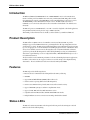
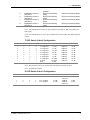
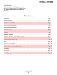
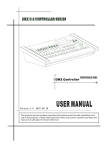
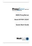
PRI Card
MTPRI-HD23B &
MTPRI-HD30B
User Guide
PRI Card User Guide
P/N 82065901, Revision B
Copyright © 1998 by Multi-Tech Systems, Inc.
All rights reserved. This publication may not be reproduced, in whole or in part, without prior expressed
written permission from Multi-Tech Systems, Inc.
Multi-Tech Systems, Inc. makes no representation or warranties with respect to the contents hereof and
specifically disclaims any implied warranties of merchantability or fitness for any particular purpose.
Furthermore, Multi-Tech Systems, Inc. reserves the right to revise this publication and to make changes
from time to time in the content hereof without obligation of Multi-Tech Systems, Inc., to notify any
person or organization of such revisions or changes.
Revision
Date
Description
A
11/14/97
Manual released.
B
5/11/98
Manual revised.
Multi-Tech, CommPlete, RASExpress, MultiExpress, and the Multi-Tech logo are trademarks of MultiTech Systems, Inc. Other trademarks and trade names mentioned in this publication belong to their
respective owners.
Multi-Tech Systems, Inc.
2205 Woodale Drive
Mounds View, Minnesota 55112
(612) 785-3500 or (800) 328-9717
U.S. Fax (612) 785-9874
Technical Support (800) 972-2439
BBS (612) 785-3702 or (800) 392-2432
Fax Back (612) 717-5888
Internet Address: http://www.multitech.com
ii
CommPlete Communications Server
Federal Communications Commission Statement
This equipment has been tested and found to comply with the limits for a Class A digital device, pursuant
to Part 15 of the FCC Rules. These limits are designed to provide reasonable protection against harmful
interference when the equipment is operated in a commercial environment. This equipment generates,
uses, and can radiate radio frequency energy, and if not installed and used in accordance with the
instruction manual, may cause harmful interference to radio communications. Operation of this
equipment in a residential area is likely to cause harmful interference, in which case the user will be
required to correct the interference at his own expense.
Warning: Changes or modifications to this unit not expressly approved by the party responsible for
compliance could void the user’s authority to operate the equipment.
Exhibit J (Consumer Instructions)
This equipment complies part 68 of the Federal Communications Commission Rules. On the outside
surface of this equipment is a label that contains, among other information, the FCC registration number.
This information must be provided to the telephone company.
As indicated below, the suitable jack (Universal Service Order Code connecting arrangement) for this
equipment is shown. If applicable, the facility interface codes (FIC) and service order codes (SOC) are
shown.
A FCC-compliant telephone cord and modular plug is provided with this equipment. This equipment is
designed to be connected to the telephone network or premises wiring using a compatible modular jack
which is Part 68 compliant. See installation instructions for details.
If this equipment causes harm to the telephone network, the telephone company will notify you in advance
that temporary discontinuance of service may be required. But if advance notice is not practical, the
telephone company will notify the customer as soon as possible. Also, you will be advised of your right to
file a complaint with the FCC if you believe it is necessary.
The telephone company may make changes in its facilities, equipment, operations, or procedures that
could affect the operation of the equipment. If this happens, the telephone company will provide advance
notice in order for you to make necessary modifications in order to maintain uninterrupted service.
If trouble is experienced with this equipment (the model of which is indicated below) please contact
MultiTech Systems, Inc. at the address shown below for details of how to have repairs made. If the
equipment is causing harm to the network, the telephone company may request you to remove the
equipment from the network until the problem is resolved.
CommPlete Communications Server
iii
No repairs are to be made by you. Repairs are to be made only by MultiTech Systems or its licensees.
Unauthorized repairs void registration and warranty.
Manufacturer:
MultiTech Systems, Inc.
Trade Name:
CommPlete
Model Number:
CC2400, CC9600
FCC Registration Number:
AU7USA-31090-DE-E
Facility Interface Code:
Service Order Code:
04DU9-ISN
6.0N
Modular Jack (USOC):
RJ48C
Service Center in USA:
MultiTech Systems, Inc.
2205 Woodale Drive
Mounds View, MN 55112
(612) 785-3500 Fax (612) 785-9874
Canadian Limitations Notice
Notice: The ringer equivalence number (REN) assigned to each terminal device provides an indication of
the maximum number of terminals allowed to be connected to a telephone interface. The termination of a
interface may consist of any combination of devices subject only to the requirement that the sum of the
ringer equivalence numbers of all the devices does not exceed 5.
Notice: The Industry Canada label identifies certificated equipment. This certification means that the
equipment meets certain telecommunications network protective, operational and safety requirements.
The Industry Canada does not guarantee the equipment will operate to the user’s satisfaction.
Before installing this equipment, users should ensure that it is permissible to be connected to the facilities
of the local telecommunications company. The equipment must also be installed using an acceptable
method of connection. The customer should be aware that compliance with the above conditions may not
prevent degradation of service in some situations.
Repairs to certified equipment should be made by an authorized Canadian maintenance facility designated
by the supplier. Any repairs or alterations made by the user to this equipment, or equipment
malfunctions, may give the telecommunications company cause to request the user to disconnect the
equipment.
Users should ensure for their own protection that the electrical ground connections of the power utility,
telephone lines and internal metallic water pipe system, if present, are connected together. This precaution
may be particularly important in rural areas.
Caution: Users should not attempt to make such connections themselves, but should contact the
appropriate electric inspection authority, or electrician, as appropriate.
This digital apparatus does not exceed the Class B limits for radio noise emissions from digital apparatus
set out in the Radio Interference Regulation of the Canadian Department of Communications.
Le présent appareil numérique n’émet pas de bruits radioélectriques dépassant les limites applicables aux
appareils numériques de la classe B prescrites dans le Règlement sur le brouillage radioélectrique édicté
par le ministère des Communications du Canada.
iv
CommPlete Communications Server
Ringer Equivalence Number
Notice: The ringer equivalence number (REN) asigned to each terminal device provides an indication of
the maximum number of terminals allowed to be connected to a telephone interface. The termination on
an interface may consist of any combination of devices subject only to the requirement that the sum of the
ringer equivalence numbers of all the devices does not exceed 5.
CommPlete Communications Server
v
vi
CommPlete Communications Server
Table of Contents
1 INTRODUCTION
Introduction............................................................................................................................................................... 2
Product Description................................................................................................................................................... 2
Features ..................................................................................................................................................................... 2
Status LEDs............................................................................................................................................................... 2
Card Components...................................................................................................................................................... 4
8-Position DIP Switch........................................................................................................................................... 4
Technical Specifications ........................................................................................................................................... 6
2 INSTALLATION
Introduction............................................................................................................................................................... 8
Safety Warnings ........................................................................................................................................................ 8
Pre-Installation Notes................................................................................................................................................ 8
Installation Procedure................................................................................................................................................ 9
3 SOLVING PROBLEMS
Introduction............................................................................................................................................................. 12
General Troubleshooting Process............................................................................................................................ 12
Startup Self Test LED Patterns ............................................................................................................................... 12
Run Time LED Status Indicators ............................................................................................................................ 12
Problems involving HEART BEAT .................................................................................................................... 13
Problems involving PHY LINK LINK................................................................................................................ 13
Problems involving RED ALARM LED............................................................................................................. 13
Problems involving YELLOW ALARM LED .................................................................................................... 13
CommPlete Communications Server
vii
viii
CommPlete Communications Server
1
CommPlete Communications Server
Introduction
1
PRI Card User Guide
Introduction
The Multi-Tech PRI Card (MTPRI-HD23B for T1 or MTPRI-HD30B for E1) is a telecommunications
interface card that provides CommPlete interconnectivity to Primary Rate ISDN (PRI) public switched
telecommunications networks. The MTPRI-HD23 provides 23 B channels that provide 23 user sessions.
The MTPRI-HD30 provides 30 B channels for 30 user sessions. The PRI card directly connects a
CommPlete to a T1 or E1 circuit without the need for an external T1 channel bank or T1 channel service
unit (CSU).
The PRI card operates as an ISDN PRI card, or as an E1 or T1 card for long-haul or short-haul applications,
using 22 AWG (0.63 mm) twisted-pair wires at up to 6000 feet (0-2 km).
This manual provides information used to install, test and troubleshoot your Multi-Tech PRI card.
Product Description
The PRI card has one RJ48C connector for a LEC line connection and 10 status LEDs. It provides
intelligent support for the ISDN B and D circuits, performing all of the call setup, management, and teardown functions on-board. The PRI card can establish and manage separate B channel connections at 64K
bps, or it can aggregate two or more B channels for an Nx64K bps logical connection. The PRI card offers a
variety of user-definable connection modes, allowing either static or dynamic bandwidth-on-demand
operation. It performs all call management as well as full-duplex DMA processing on each channelized
data stream. Logical channel protocols are configurable for PPP, or Multilink PPP link-level protocols, or
raw (unframed) data mode.
The 16-bit interface ensures maximum performance for the most demanding data-intensive applications.
In addition, 8-bit transfers are also supported. There are no restrictions imposed on alignment during
data transfers. The on-board firmware resides in an 8 bit wide 512K byte Flash ROM.
Features
The PRI card provides the following features:
• Extensive selection of Extended mode and Expanded mode memory addressing
• ISDN BRI
• supports PPP and Multilink PPP (MLPPP) Link Level Protocols
• extensive statistics reporting (link level and call management)
• extensive status LED monitoring of Faults, LEC circuit, and host interface activity
• support of PRI ISDN, Q.921, Q.931, and NI-2 compliant LEC circuits
• support of AT&T, MCI (and other) Multi-Rate Bearer services
• compatible with AT&T 4ESS and 5ESS, NT DMS-100 and DMS-250 switches
• multiple simultaneous remote connections at N x 64K bps bandwidth on demand
Status LEDs
The PRI card contains 10 status LEDs on the front panel. The front panel is shown in Figure 1 and each
LED is described in the following listing.
2
CommPlete Communications Server
1 Introduction
Figure 1. PRI Card Front Panel
LED Indicator
PHYSICAL LINK
Color
Green
DATA LINK
Green
RED ALARM
Red
YELLOW ALARM
Yellow
DATA CHANNEL
CONTROL
LED Indicator
HOST FIFO
HEART BEAT
Green
Green
Color
Green
Green
SYSTEM ERROR
Red
CHANNEL CLOCK
Green
CommPlete Communications Server
Indication
Lit - Indicates LEC circuit connection is active and signaling is
correct.
Off - Indicates absence of valid LEC circuit signaling.
Lit - Indicates reception of a Link Up message from LEC.
Off - Indicates a reception of a Link Down message from LEC.
Lit - Indicates red alarm pattern is being received
indicating an improper receive signal or no receive signal. This
alarm can occur as a result of a high error rate or improper line
configuation. When this alarm occurs a yellow alarm is sent to the
other end of the network
Off - Indicates normal operation
Lit - Indicates yellow alarm
Off - Indicates normal operation
Changes state with each D-Channel message
Not Currently used.
Indication
Blinks - Indicates FIFO interrupt during normal operation.
Lit - Indicates unrecoverable error
Blinking - Blinking at a one-second rate indicates normal operation.
Lit - Main processor failure (possibly FLASH is not programmed or
destoryed).
Momentarily lits when startup self test is completed.
3
PRI Card User Guide
Card Components
The 8-position DIP switch is located on the lower portion of the card and is used to set the operating
modes of the card. The T1 line connector is a RJ48C connector located on lower back of the card and is
used to connect to the T1 line facility. The PRI card components are descirbed in detail in the following
sections.
J9
J101
J8
J103
Status
LEDs
J100
LED 1
LED 2
LED 3
LED 4
LED 5
LED 6
LED 7
LED 8
LED 9
LED 10
Power Supply Fuse
F5 (3 Amp)
F5
OPEN
F1
F2
F3
1 2 3 4 5 6 7 8 F4
J1
8-Position DIP Switch
T1 Line
Connector
T1 Line Protection
Fuses F1-F4 (3 Amp)
Figure 2. Card Components
8-Position DIP Switch
The 8-position DIP switch shown in Figure 4 is used to select various PRI card operating modes.
The default settings of the DIP switch module are also shown in Figure 3.
OPEN
12345678
Figure 3. 8-position DIP Switch
The DIP-switch selections are described in the following listings.
Switch
Number
1
4
Function
Open
Closed
2
Selects Jitter Attentuation
path
Selects TOS
Activate Jitter Attentuation in
transmit path
Normal
3
Selects local loopback
4
Selects remote loopback
Activate Jitter Attentuation
in receive path
Transmit data inputs
ignored, instead transmits
a stream of ones
Local loopback test
enabled
Remote loopback test
Normal
Normal
CommPlete Communications Server
1 Introduction
5
enabled
Refer to the following
listing
Refer to the following
listing
Refer to the following
listing
Refer to the following
listing
Equalization Control 4.
See Note 1
Equalization Control 3.
See Note 2
Equalization Control 2.
See Note 2
Equalization Control 1.
See Note 2
6
7
8
Refer to the following listing
Refer to the following listing
Refer to the following listing
Refer to the following listing
Note 1: Used with DIP-Switches 6 thru 8 for pulse equalization, line build-out (LBO), and equalizer gain
limit settings.
Note 2: Used with DIP-Switches 5,7,8 for pulse equalization, line build-out (LBO), and equalizer gain limit
settings.
T1 DIP Switch 5 thru 8 Configuration
DIP#5
0
0
0
0
0
0
0
0
1
DIP#6
0
0
1
1
0
0
1
1
1
DIP#7
0
1
0
1
0
1
0
1
1
DIP#81
0
0
0
0
1
1
1
1
1
Function
T1 Long Haul
T1 Long Haul
T1 Long Haul
T1 Long Haul
T1 Long Haul
T1 Long Haul
T1 Long Haul
T1 Long Haul
T1 Short
Haul
Tx Level
0.0 dB
-7.5 dB
-15 dB
-22.5 dB
0.0 dB
-7.5 dB
-15 dB
-22.5 dB
533-655ft/
2.4dB
Cable
100Ω TP
100Ω TP
100Ω TP
100Ω TP
100Ω TP
100Ω TP
100Ω TP
100Ω TP
100Ω TP
RcvLevel
36 dB
36 dB
36 dB
36 dB
26 dB
26 dB
26 dB
36 dB
36 dB
Note 1: DIP Switch #8 sets the receive equalizer gain (EGL) during T1 long haul operations.
Note 2: applicable when enabled.
E1 DIP Switch 5 thru 8 Configuration
DIP#5
1
DIP#6
0
DIP#7
0
DIP#8
0
Function
E1 Short Haul
Tx Level
ITU Rec G.703
1
1
0
0
0
1
1
0
E1 Long Haul
E1 Long Haul
0.0 dB
0.0 dB
CommPlete Communications Server
Cable
120Ω TP/
75Ω=Coax
100Ω TP
100Ω TP/
75Ω=Coax
RcvLevel
12 dB
43 dB
43 dB
5
PRI Card User Guide
Technical Specifications
The PRI card operating characteristics and specifications are provided below.
• CPU
Intel 960 (16 MHz RISC processor)
• Dynamic RAM
4 Mb
• Program Memory
512K bytes Flash
• Serial I/O channels supported
23B + D on MTPRI-HD23B and
30B + D on MTPRI-HD30B
• Serial I/O operation
Simultaneous full duplex DMA (all
channels)
• Diagnostic/status indicators
10 LEDs
• Line Coding
T1 - B8ZS or AMI (programmable), E1 HDB3
• Framing
T1 - ESF or D4 (programmable), E1 ESF
• Capture Frequency
T1 - 1.544 Mbps/E1 2.048 M +/- 200 bps
• Input/Output Impedence
T1 - 100 ohms/E1 120 ohms +/- 5%
• Received Signal Level Range
T1 - DSX-1 level to -27.5 db, E1 ITU G.703 to -43
• Line Buildout
T-1 7 levels (programmable) 0-320 meters, E1
short haul
• Transitted Signal Level Range
T-1 DSX-1 into 100 ohms, E1 G.703 into 120
ohms
• Pulse Density and Zeroes Enforcement T-1 Per AT&T Pub 62411, E1 G.703/G.823
• Line Loopback Set Inband Code (1000) repeating binary pattern
• Line Loopback Reset Inband Code
(100) repeating binary pattern
• Interface Connector
ISDN RJ-48C
• Operating Temperature
• Relative Humidity
to 90% without condensation
• Dimensions:
9.2" H x 0.9” W x11.5 D ” (23.3 x 2.3 x 29.2 cm)
• Power Requirements:
+5V (+/-10%) 1.25 A
• ISDN Signaling (PRI) Standards
Q.921 and Q.931
• Standards Supported
6
0-55 degrees C (32-131 degrees F)
National ISDN-2, AT&T 4ESS and 5ESS,
Northern Telecom DMS-250
CommPlete Communications Server
2
CommPlete Communications Server
Installation
7
PRI Card User Guide
Introduction
This chapter describes how to install the PRI card into a CommPlete Communication system. This
equipment should be installed only by a qualified service person.
Safety Warnings
• Never install telephone wiring during a lightning storm.
• Never install telephone jacks in wet locations unless the jacks are specifically designed for wet
locations.
• Never touch uninsulated telephone wires or terminals unless the telephone line has been disconnected
at the network interface.
• Use caution when installing or modifying telephone lines.
• Avoid using a telephone (other than a cordless type) during an electrical storm. There may be a remote
risk of electrical shock from lightning.
• Do not use the telephone to report a gas leak in the vicinity of the leak
• Ports that are connected to other apparatus are defined as SELV. To ensure conformity to EN 41003,
ensure that these ports are only connected to the same type on the other apparatus.
Pre-Installation Notes
Warning: Interconnection directly, or by way of other apparatus, of ports marked “SAFETY WARNING
see instructions for use” with ports marked or not so marked may produce hazardous conditions on the
network. Advice should be obtained from a competent engineer before such a connection is made.
• All installation must be done by a qualified service person.
• To reduce emissions, be sure to use blanking plates to cover empty slots in the CC9600 or CC2400
chassis.
• When transporting the MTPRI-HD23B, wrap it in an anti-static bag (such as the original shipping
packaging). When handling the board, observe anti-static procedures, such as the DOD-STD-1686 or
equivalent.
8
CommPlete Communications Server
2 Installation
Installation Procedure
Typically the PRI card will be set up with the 8-position DIP switches all in the DOWN (Closed) position.
This setting is for a T1 long haul configuration. If your configuration is different, set the 8-position DIP
switches according to the T1 or E1 DIP Switch 5 thru 8 Configuration listing in Chapter 1 of this User
Guide.
Warning:
Power the CommPlete system off before installing the PRI card. Under no circumstances should the PRI
card be installed in an energized system.
Perform the following steps to install the PRI card in the CommPlete chassis:
1.
Unpack the PRI card from its packaging and save the packaging for possible future use. Perform a
visual inspection of the card. If you are concerned about its condition, call Technical Support for
instructions.
2.
Determine the operating mode of the PRI card, refer to the T1/E1 DIP Switch 5 thru 8 Configuration
listings in Chapter 1 of this User Guide.
3.
The PRI card must be installed next to the RASCard in the chassis. Remove a blank panel or previous
PRI card from that slot.
4.
Supporting the PRI card by the front panel and the bottom edge of the card, place it into the open
slot. Make sure the edges of the PRI card mate properly with the metal guides in the chassis.
5.
Slide the PRI card into the chassis until you feel the card’s connectors mate with the chassis bus
connectors.
6.
Tighten the PRI card retaining screws.
7.
Connect the PRI card to the T1/E1 line.
8.
Turn on system power.
CommPlete Communications Server
9
PRI Card User Guide
10
CommPlete Communications Server
3 Solving Problems
CommPlete Communications Server
11
PRI card User Guide
Introduction
This chapter provides the processes and procedures to help solve PRI card problems. The steps are
generally presented in the recommended chronological order.
General Troubleshooting Process
At the first indication of a problem, perform the steps below. The recovery options are listed in the
recommended chronological order (from simplest and most likely to most complex and least likely cause).
1.
2.
Verify that your site meets the specifications (Environmental Requirements, Physical
Characteristics, Power Requirements, On-Board Hardware Resources, Host Interface,
LEC Interface Standards, and Primary Rate ISDN Standards) earlier in this manual.
CSU/T1
Verify proper hardware installation procedure (earlier in this manual).
3. Check the LEC cabling (earlier in this manual).
4.
Check the Startup Self Test, refer to the Startup Self Test LED Patterns in the following section.
5.
Check the Run Time Test, refer to the Run Time LED Status Indicators in the following section .
6.
Re-try the failed operation.
7.
Call your LEC representative and/or your ISDN service provider. Have the information that you
recorded during hardware installation available.
8.
Call Multi-Tech’s Tech Support department.
Startup Self Test LED Patterns
Each time the PRI card is reset (i.e., the CommPlete is powered on or the system reset is asserted) the PRI
card firmware executes a series of startup self-test routines. The routines perform 8 basic tests which
require a total of approximately 10-15 seconds to complete, and during which the yellow LEDs report the
progress of the tests. The yellow LEDs display a test status pattern (the applicable LED is lit) as each test
executes.
As each test passes, its pattern is displayed by the yellow LEDs. The subsequent test then begins execution
and its pattern is likewise displayed. This process continues until the final test executes successfully, after
which only the Frame Sync LED is lit for a short time, indicating successful completion of the startup selftest phase.
If any test fails, its LED pattern is flashed continuously at a 1/2 second rate and the PRI card will suspend
further operations until the problem is fixed.
Run Time LED Status Indicators
On successful completion of the startup self-tests, the yellow LEDs display the real-time operating status of
the PRI card hardware and software. In this mode, the LED meanings are defined by a COMM Engine
12
CommPlete Communications Server
3 Solving Problems
Process. The LEDs can be used for low-level troubleshooting of the ISDN connection. Some of the most
common reasons for an ISDN connection failure are:
Problems involving HEART BEAT
• If the HEART BEAT LED is lit, it indicates the firmware has encountered an unrecoverable error. Verify
that the firmware has had time to load properly and that processes are successfully completed. Call
Tech Support if the problem persists.
Problems involving PHY LINK LINK
• The ISDN circuit is not connected to the PRI card. If the PHY LINK LED is Off it indicates the absence
of valid LEC circuit signaling. The ISDN circuit is not connected to the PRI card properly. Look for
missing or broken wiring from the LEC distribution facility, malfunctioning interconnect cabling
(broken wires, bad connectors, incorrect connector installation, etc.).
Recommended action: contact your LEC representative.
Problems involving RED ALARM LED
The PRI card is experiencing a high error rate or is not configured properly. If the RED ALARM LED is
lit, it indicates an improper receive signal or no receive signal. Check the configuration of the PRI card
with the PRISTATUS command at the controller. Contact your LEC representative or Multi-Tech's
Technical Support Department if you continue to experience this alarm.
Problems involving YELLOW ALARM LED
The device at the other end of the network is in red alarm. It may not be receiving the signal from the
PRI card. Contact your LEC representative.
CommPlete Communications Server
13