1
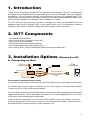
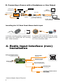
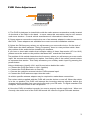
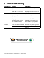
Expand Your Factory Radio to your car’s FM stereo iPod® MP3 Players other audio sources Owner’s Universal Owner’s Manual Manual Media Gateway IS77 PXAMG For Factory Radio Aftermarket Radio OR ®, ®, Peripheral Electronics Peripheral Electronics a division ofof AAMP of America™ a division of AAMP America™ 13160 56thClearwater, Court Clearwater, 13160 56th Court Florida Florida 33760 33760 Ph. 866-788-4237 Ph. 800-477-2267 ext. 230 [email protected] [email protected] ©2007of AAMP of Florida, Inc. ©2009 AAMP Florida, Inc. Rev. 10-28-08 Table of Contents 1. 2. 3. 4. Introduction IS77 Components Installation Options Radio Input Interface (PURI) Installarion 5. Troubleshooting 6. Warranty Information Pages 1 1 1 2 4 5 1. Introduction Thank you for choosing the iSimple IS77 as your audio input solution. The IS77 is designed to provide the connecting link between your audio source and your FM radio. Using the supplied accessories, you can connect virtually any audio source into any FM equipped radio. This interface has a universal input that can be configured to accept an audio signal from any source with an RCA connection or a standard 3.5mm “Headphone” output. The IS77 will route the audio from your device through your factory or aftermarket radio not equipped with a built in auxiliary input. If your audio source is an iPod featuring a docking connector, this interface will also charge the iPod’s battery, when connected. 2. IS77 Components • One Radio Input Interface • One 3.5 mm to 3.5 mm Audio Cable (4ft.) • One 3.5mm to RCA adapter • One Power Cable with a On/Off Switch • One iPod Audio/Video Cable Outputs (5ft.) • One “factory look” 3.5mm Dash/Panel Mount Audio Input Cable (6ft.) 3. Installation Options (Choose A or B) A. Connecting an iPod Connect To SWITCH Connects to On/Off Switch Antenna Out* Connect To iPod Fuse Fuse PURI Connects to iPod iPod (not included) MENU iPod Audio Cable (5 ft.) Antenna In * iPod Specific installation instructions 1) Connect the two audio connectors from the iPod cable to the audio inputs on the PURI. iPod Conection To Connects to two-pinConnect 2) Connect the power connector Not onUSEthe iPod cable to the connector labeled SWITCH On/Off Switch MP3 Fuse “Connect to iPod” in the PURI wiring harness. (not included) 3/8” hole Out* connector from the iPod cable is intended for video playback from iPods that 3) Antenna The Yellow OR PURI support this function. Route this Video connection to any video display that is not in view 3.5 mm to 3.5 mm 3.5 mm to RCA “factory look” 3.5 mm of the driver while operating the automobile. Audio Cable (4 ft.) Adapter Dash/Panel Mount Audio Input Cable (6 ft.) Antenna In * 4) Route the iPod connector to your chosen iPod location in your automobile. Common audio source locations are the glove box, center console or in a mounted iPod cradle.(not You will need to included) access the iPod in order to change music selections, etc.. 3. Connecting a source with RCA outputs iPod Audio Cable (5 ft.) Antenna In * B. Connecting a Source with a Headphone or Line Output Connects to On/Off Switch Antenna Out* iPod Conection Not USE Connect To SWITCH Fuse MP3 (not included) 3/8” hole PURI OR “factory look” 3.5 mm Dash/Panel Mount Audio Input Cable (6 ft.) 3.5 mm to RCA Adapter Antenna In * 3.5 mm to 3.5 mm Audio Cable (4 ft.) audio source (not included) Installing the 3.5 Dash Panel Mount Audio Input 3. Connecting a source with RCA outputs 3/8” iPod Conection To Not USE Connects to 3.5 mm DashConnect “factory look” Panel Mount Audio input (6 ft.) SWITCH On/Off Switch Fuse 1) Choose mounting position of dash mount audio input and carefully drill 3/8” mounting Antenna Out*connector. hole. Install PURI 3.5 mm to 3.5 mm Audio Cable (4 ft.) 2) Connect your audio device to the newly installed audio input via the supplied 3.5 mm to 3.5 mm connection cable. RCA to RCA (not included) audio source (not included) Antenna In * 4. Radio Input Interface (PURI) Installation * Some radios require the addition of antenna connection adapters Radio Tuning Frequency Antenna Out Use to select best operating frequency for your area to FM radio* 87.9 88.3 Tuning Frequency (MHz FM) PURI Left & Right Audio Input Audio Input °L Power 12V DC Ground Antenna Input Antenna Output TOP VIEW ° ° ° ° Universal Radio Input Stereo Audio to FM Radio °R Antenna Input Factory or Upgraded Radio* from vehicle antenna* Ground Connection Connect to a clean ground point On/Off Switch 3/4” mounting hole 2A Fuse * Antenna Adapter May be Required BACK VIEW LEVEL L Gain Adjustment +H Connects to Power Source ACC 12VDC Power when key-on 3/4” mounting hole PURI Gain Adjustment 2A Fuse Connects to Power Source ACC 12VDC Power when key-on BACK VIEW LEVEL L +H Gain Adjustment Use to match volume of PURI to volume of FM radio stations 1) The PURI is designed to install Inline with the radio antenna connection usually located on the back of the radio in the dash. In some cases this connection may be at a remote radio tuner location. Consult vehicle manufacturer’s information in these cases. 2) Some antenna connections require the use of an antenna adapter in order to connect to the PURI. These adapters are available from most car audio installation retailers. 3) Select the FM frequency where you will access your new audio device. On the side of PURI where the label indicates “Tuning Frequency” there is a two position switch. Note the position of the switch before installing the interface. If you have a local radio station that occupies either of these frequencies (87.9 or 88.3) please move the switch to the position that does NOT match the local station. The position of this switch determines the frequency where you will access your new audio input. We recommend choosing one option, and setting one of the radio’s preset buttons to represent that station. This easily accesses your auxiliary audio input by pressing the preset button. Using a Multimeter, identify 12V+ and Ground wires behind the radio. a. Connect the PURI Red wire to 12V+ (Ignition) b. Connect the PURI Black wire to Ground c. Connect the vehicle’s antenna into the PURI antenna input* d. Connect the PURI antenna output into the radio* *A vehicle specific antenna adaptor may be required to make these connections The rocker switch supplied with the PURI will turn the device on and off. When the switch is in the on position, the PURI will interrupt the incoming antenna signal to deliver the cleanest signal possible from your device through your FM radio. To regain standard FM reception, move the switch to the Off position. 4) Once the PURI is installed correctly, be sure to properly set the audio level. When set correctly, the audio level of the PURI will match the volume of typical FM radio stations. 5. Troubleshooting Symptom Cause Remedy No Audio from the Aux source 1) IS77 is turned off Move rocker switch to ON position 2) Connection cables are disconnected Check all interconnects for proper connection 3) The radio is not on the correct station Verify that the FM radio is tuned to the frequency on the side of the interface. 1) The power connection on the IS77 is disconnected Connect power cable according to Configuration 1 in Section 3 2) The fuse may be blown in the power plug on the iPod specific connection cable If fuse is blown, replace with equivalent fuse 1) Improper selection of IS77 frequency Tune to the frequency specified on the side of the IS77 interface. 2) local radio station is interfering with the Auxiliary input device Change the frequency setting on the side of the IS77 to the other position, and use the new frequency to access the audio source 1) the volume is down on the audio source Turn up the volume on the source to ensure best sound quality through the IS77 The IS77 Gain is set too low Adjust the gain setting on the back side of the IS77 iPod does not charge Noise / Static Low audio For Best Performance Have It Professionally Installed. iPod is a trademark of Apple Inc., registered in the U.S. and other countries. iPhone is a trademark of Apple Inc. 6. Warranty Information One Year Limited Warranty The quality controls used in the manufacture of this product will ensure your satisfaction. This warranty applies only to the original purchaser of this product from an authorized Peripheral Electronics dealer. This warranty covers any supplied or manufactured parts of this product that, upon inspection by Peripheral Electronics authorized personnel, is found to have failed in normal use due to defects in material or workmanship. This warranty does not apply to installation expenses. Attempting to service or modify this unit, operating this unit under conditions other than the recommended voltage will render this WARRANTY VOID. Unless otherwise prescribed by law, Peripheral Electronics shall not be liable for any personal injury, property damage and or any incidental or consequential damages of any kind (including water damage) resulting from malfunctions, defects, misuse, improper installation or alteration of this product. All parts of this Peripheral Electronics product are guaranteed for a period of 1 year as follows: Within the first 12 months from date of purchase, subject to the conditions above, Peripheral Electronics will repair or replace the product at their discretion, if it is defective in material or workmanship providing it is returned to an Authorized Peripheral Electronics’ dealer, with PROOF OF PURCHASE from an authorized Peripheral Electronics dealer. Warning: This equipment may be reset by unintentional electrostatic discharge during operation. Exposure to direct sunlight or extreme heat may cause damage or malfunction. FCC Class B Radio Frequency Interference Statement This equipment has been tested and found to comply with the limits for a Class B digital device, pursuant to Part 15 of FCC rules. These limits are designed to provide reasonable protection against harmful interference in a residential installation. This equipment generates, uses, and can radiate radio frequency energy and, if not installed and used in accordance with the instructions, may cause harmful interference to radio communications. However, there is no guarantee that interference will not occur in a particular installation. If this equipment does cause harmful interference to radio or television reception, which can be determined by turning the equipment off and on, the user is encouraged to try to correct the interference by one or more of the following measures: 1. Re-orientate or relocate the receiving antenna. 2. Increase the separation between the equipment and receiver. 3. Connect the equipment into an outlet on a circuit different from that of which the receiver is connected. 4. Consult the dealer or an experienced radio / television technical for help. Notice : The changes or modifications not expressly approved by the party responsible compliance could void the user authority to operate the equipment. www.peripheralelectronics.com Peripheral Electronics®, a division of AAMP of America™ 13160 56th Court Clearwater, Florida 33760 Ph. 800-477-2267 ext. 230 [email protected] ©2009 AAMP of Florida, Inc.