1
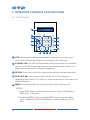
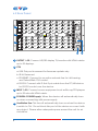
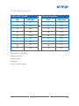
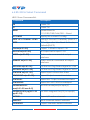
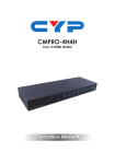
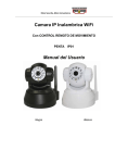
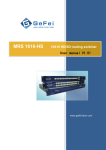
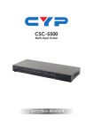
CMSI-3232/1616/88
HDMI Matrix
Operation Manual
DISCLAIMERS
The information in this manual has been carefully checked and
is believed to be accurate. Cypress Technology assumes no
responsibility for any infringements of patents or other rights of third
parties which may result from its use.
Cypress Technology assumes no responsibility for any inaccuracies
that may be contained in this document. Cypress also makes no
commitment to update or to keep current the information contained
in this document.
Cypress Technology reserves the right to make improvements to this
document and/or product at any time and without notice.
COPYRIGHT NOTICE
No part of this document may be reproduced, transmitted,
transcribed, stored in a retrieval system, or any of its part translated
into any language or computer file, in any form or by any means—
electronic, mechanical, magnetic, optical, chemical, manual, or
otherwise—without express written permission and consent from
Cypress Technology.
© Copyright 2012 by Cypress Technology.
All Rights Reserved.
Version 1.0 September 2012
TRADEMARK ACKNOWLEDGMENTS
All products or service names mentioned in this document may be
trademarks of the companies with which they are associated.
SAFETY PRECAUTIONS
Please read all instructions before attempting to unpack, install or
operate this equipment and before connecting the power supply.
Please keep the following in mind as you unpack and install this
equipment:
•
Always follow basic safety precautions to reduce the risk of fire,
electrical shock and injury to persons.
•
To prevent fire or shock hazard, do not expose the unit to rain,
moisture or install this product near water.
•
Never spill liquid of any kind on or into this product.
•
Never push an object of any kind into this product through any
openings or empty slots in the unit, as you may damage parts
inside the unit.
•
Do not attach the power supply cabling to building surfaces.
•
Use only the supplied power supply unit (PSU). Do not use the PSU
if it is damaged.
•
Do not allow anything to rest on the power cabling or allow any
weight to be placed upon it or any person walk on it.
•
To protect the unit from overheating, do not block any vents or
openings in the unit housing that provide ventilation and allow for
sufficient space for air to circulate around the unit.
REVISION HISTORY
VERSION NO.
DATE DD/MM/YY SUMMARY OF CHANGE
RDV1
13/09/12
Preliminary Release
CONTENTS
1. Introduction�������������������������������������������� 1
2. Applications������������������������������������������� 1
3. Package Contents�������������������������������� 1
4. System Requirements���������������������������� 1
5. Features�������������������������������������������������� 2
6. Operation Controls and Functions������� 3
6.1 Front Panel����������������������������������������3
6.2 Rear Panel�����������������������������������������5
6.3 RS-232 Protocols�������������������������������6
6.4 RS-232 & Telnet Command�������������7
7. Connection Diagram���������������������������� 9
8. Specifications�������������������������������������� 10
9. Acronyms��������������������������������������������� 11
1. INTRODUCTION
The Modularized HDMI Matrix series can route the signal of 32, 16 or 8
sources to any connected 32, 16 or 8 displays, providing resolution up
to Full HD 1080p and WUXGA (1920x1200@60HzRB). Besides the regular
matrix functionality, the matrix models are very attractive to the
integrators because of their great flexibility, with the most advanced
modularization design these models can be setup as a matrix of HMDI,
DVI-D, or their any combinations (count with eight, for example, a
matrix with 24-HDMI-in/8-DVI-IN and 16-HDMI-OUT/16-DVI-OUT), all you
need to do is to swap the input or output modules as you wish.
2. APPLICATIONS
• Public information display
• Educational demo
• Professional Presentation
• Advertising display
3. PACKAGE CONTENTS
• 1 x Enclosure 3232/1616/88 (including control board, & power(s))
• 4 x Input Module Board (Optional)
• 4 x Output Module board (Optional)
• 2 x Power Cord/3232& 1616 or 1 x Power Cord/88
4. SYSTEM REQUIREMENTS
Input source equipments like DVD/Blu-ray players and output display
TV/monitor with HDMI connection cables.
1
5. FEATURES
• HDMI, HDCP 1.1 and DVI 1.0 compliant
• Changeable input and output board
• Input and output module types can be mixed and added in
increment of 8 from 8x8 up to 32x32 with HDMI, DVI and CAT5e/6/7
interfaces
• Supports LPCM 7.1CH, Dolby TrueHD, Dolby Digital Plus and DTS-HD
Master Audio transmission
• Supports a wide range of PC and HDTV resolutions from VGA to
WUXGA and 480i to 1080p
• Supports RS-232, Telnet and Ethernet controls
• Supports redundant power supply (on 3232 & 1616)
• HDMI cable length with a resolution 1080p/8bits&12bits the Input/
Output source can be 15/15m(8bit) and 10/10m(12) away
• EDID modes:
a.Automatic mode: Taking EDID from the lowest output port
b.Manual mode: Can assign any output to any input port
c.Standard mode: factory default
2
6. OPERATION CONTROLS AND FUNCTIONS
6.1 Front Panel
1
3
R: STANDBY
FLASH: ALERT
POWER
RETURN
7
8
9
LOCK
MENU
4
5
6
SAVE
1
2
3
RECALL
OUT/IN
0
+
ENTER
2
10
PAGE
5
11
4
12
PAGE
ALL
13
6
8
7
9
1 LCM: Displays the setting information of each input and output
and other setting information according to the selection.
2 POWER & LED: This LED will illuminate when the power is in standby
mode. If the LED is flashing it means the temperature inside is too
high and air circulation is highly suggested.
3 RETURN: Press this button to return back/exit the current selection.
4 PAGE▲▼◄►: Use these buttons to flip the LCM’s page for
displaying the current I/O status or when entering into the menu for
detail selection.
5 MENU: Press this button to enter into the menu selections of
A.EDID
1.Auto EDID: Base on the first connected output TV/Display’s EDID from 1~32 ports.
2. Standard EDID: Use the built-in EDID which supports video up to 1080p@60/WUXGA@60RB and audio supports LPCM 2CH.
3
3. Manual EDID: Support independent EDID by appoint input and output ports.
B. IP
1. IP address,
2. Netmask,
3. Gateway.
C.Temperature
1. Temperature 1,
2. Temperature 2, these figures shows the temperature of the device inside.
6 ALL: Press this button to select all outputs with one input.
7 0~9: Press these numbers when selecting input output ports.
8 OUT/IN: Press this button to select input source to displaying on
output display. The sequence should be OUT/IN→number(s) for
input source→OUT/IN→a number for output display→Enter.
9 +: Press this button when selecting more than one output for an
input selection. (This button works only under OUT/IN function)
10 LOCK & LED: Press this button to lock all the function buttons on
panel. The LED will illuminate, to unlock press it again.
11 SAVE: Press this button to save the present setting of the I/O. There
are 3 sets available for saving.
12 RECALL: Press this button to recall from the saving settings of 1~3.
13 ENTER: Press this button every time to confirm the setting or the
selection.
4
6.2 Rear Panel
100-240VAC
50/60 Hz
OUTPUT
1
8
9
16
17
24
1
25
32
RS232
2
ETHERNET
IR IN
USB
OUTPUT 0
CPU
INPUT
1
8
9
16
17
24
25
32
3
4
5
1 OUTPUT 1~32: Connect HD/3D display TV/monitor with HDMI cables
up to 32 displays.
2 CPU
a.USB: This port is reserved for firmware update only.
b.IR IN: Reserved.
c.ETHERNET: Connect to an active network line for LAN serving and Telnet/Web GUI control.
d.RS-232: Connect with D-Sub 9-pin cable from the PC/NB device for RS-232 control over the device.
3 INPUT 1~32: Connect source equipment such as Blu-ray/PS3 players
up to 32 sets with HDMI cable.
4 POWER & POWER Supply: When the device will automatically turns
on when connecting with power supply.
5 Ventilation Fan: This fan will automatically turns on when the device
is switch to ON. Do not block this port of the device or cover it with
any object. Please allow adequate space around the unit for air
circulation
5
6.3 RS-232 Protocols
CMSI-3232/1616/88
Remote Controller
PIN
Definition
PIN
Definition
1
NC
1
NC
2
TxD
2
RxD
3
RxD
3
TxD
4
NC
4
NC
5
GND
5
GND
6
NC
6
NC
7
NC
7
NC
8
NC
8
NC
9
NC
9
NC
Baud Rate: 19200bps
Data Bit: 8 bits
Parity: None
Stop Bit: 1
Flow Control: None
6
6.4 RS-232 & Telnet Command
HELP: Show Command list.
Command
Description
P0
Power Off
P1
Power On
RESET
System Reset to
O1I1,O2I2,O3I3,O4I4,O5I5.... Reset
IPCONFIG
Display the current IP config
SETIP <IP> <SubNet> <GW>
Setting IP.Sbunet.GGateWay (Static IP)
RSTIP
IP Configuration Was Reset To Factory
Defaults(DHCP)
OxxIxx(x:01~32)
Output 1~32 set to Input 1~32
ALLOUT xx(x:01~32)
All Output set to Input 1~32
MUTE xx(x:01~32)
Video mute command at output
interface
UNMUTE xx(x:01~32)
Video unmute command at output
interface
HPDLOW xx(x:01~32)
Pull the Hot-Plug-Detect signal to 'LOW'
HPDHIGH xx(x:01~32)
Pull the Hot-Plug-Detect signal to 'HIGH'
STATUSIN xx(x:01~32)
Report Input connection status
STATUSOUT xx(x:01~32)
Report Output connection status
STATUSALL
Report ALL Output connection status
STATUSEDID
Report ALL INPUT EDID mode&port
SETEDIDMODE ii
mm(ii:01~32 mm:0~2)
set EDID mode(mm)to Input(ii)
SETEDIDPORT ii pp(ii:01~32
pp:01~32)
Set EDID Assigned Port(PP) to Input(ii)
ACTIVE
Report I/O active channels
INDETECT
Input channels detect indicator
OUTDETECT
Output channels detect indicator
7
SHOWMUTE
SETIPADDR <IP>
Show mute ststus of all output(0=not
muted,1=muted
Setting iIP address
SETSNMASK <SubNet>
Setting subned mask
SETWADDR <GW>
Setting gateway IP address
RDIPADDR
Display the current IP address
RDSNMASK
Display the current subnet mask
RDGWADDR
Display the current gateway IP address
Q
Display controller firmware version
Note: All the RS-232 command will be not executed unless followed
with a carriage return. Commands are case-insensitive
8
7. CONNECTION DIAGRAM
Output Display TV/Monitors up to 32
RS232 Equipped
PC or Notebook
Wireless
Router
100-240VAC
50/60 Hz
OUTPUT
1
8
9
16
17
24
25
32
RS232
ETHERNET
IR IN
USB
OUTPUT 0
CPU
INPUT
1
8
9
16
17
24
25
32
or
or
Input Source equipments up to 32
9
Power Supply
8. SPECIFICATIONS
Video Bandwidth
225MHz/6.75Gbps
Input ports
32/16/8 x HDMI or DVI or CAT5e/6/7
Output port
32/16/8 x HDMI or DVI or CAT5e/6/7
Power Supply
2 x AC 110~240V (US/EU standards, CE/
FCC/UL certified)*3232 & 1616
1x AC 110~240V (US/EU standards, CE/
FCC/UL certified)*88
HMDI Cable I/O Distance
15m/8-bit I/O, 10m/12-bit I/O
Dimensions (mm)
482(W) x 369(D) x 226(H) 3232
482(W) x 388(D) x 144.5(H) 1616
482(W) x 380(D) x 100(H) 88
Weight(g)
15,000 (CMSI-3232HS)/
12,500(CMSI-1616HS)/
11,000(CMSI-88HS)
Chassis Material
Metal
Silkscreen Color
Black
Operating Temperature
0 ˚C~40 ˚C/32 ˚F~104 ˚F
Storage Temperature
−20 ˚C~60 ˚C/−4 ˚F~140 ˚F
Relative Humidity
20~90 % RH (non-condensing)
Power Consumption
90W/88, 130W/1616, 230W/3232
9. ACRONYMS
ACRONYM
11
COMPLETE TERM
CYPRESS TECHNOLOGY CO., LTD
Home page: http://www.cypress.com.tw
20121206 MPM-CMSI3232