1
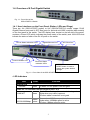
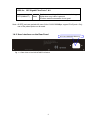
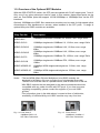
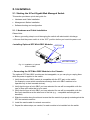
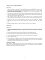
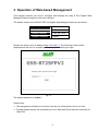
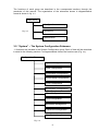
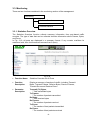
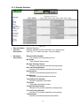
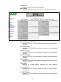
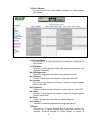
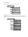
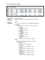
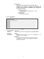
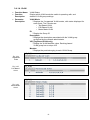
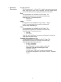
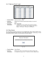
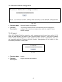
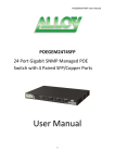
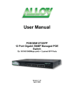
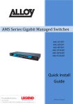
User Manual GSS-8T2SFPV2 8 Port Gigabit Web Managed Switch 8x 10/100/1000Mbps ports + 2 paired SFP Ports Version: 1.01 August 1st, 2005 Table of Contents CAUTION ---------------------------------------------------------------------------------------------------------- III ELECTRONIC EMISSION NOTICES ----------------------------------------------------------------------------- III AUSTRALIAN C-TICK COMPLIANCE --------------------------------------------------------------------------- III ABOUT THIS USER MANAUAL --------------------------------------------------------------------------------- 1 1. INTRODUCTION ---------------------------------------------------------------------------------------------- 2 1.1. OVERVIEW OF 8 PORT GIGABIT WEB MANAGED SWITCH ------------------------------------------- 2 1-2. CHECKLIST ------------------------------------------------------------------------------------------------- 3 1-3. FEATURES -------------------------------------------------------------------------------------------------- 4 1.4. OVERVIEW OF 8 PORT GIGABIT WEB MANAGED SWITCH ------------------------------------------- 5 1.4.1. User Interfaces on the Front Panel (Button, LEDs and Plugs) ------------------------- 5 1.4.2. User Interfaces on the Rear Panel ------------------------------------------------------------ 6 1.5. OVERVIEW OF THE OPTIONAL SFP MODULES -------------------------------------------------------- 7 2. INSTALLATION------------------------------------------------------------------------------------------------ 8 2.1. STARTING THE 8 PORT GIGABIT WEB MANAGED SWITCH------------------------------------------- 8 2.1.1. Hardware and Cable Installation--------------------------------------------------------------- 8 2.1.2. Cabling Requirements ------------------------------------------------------------------------- 10 2.1.2.1. Cabling Requirements for UTP Ports------------------------------------------------- 10 2.1.2.2. Cabling Requirements for 1000SX/LX/ZX SFP Modules ------------------------ 10 3. OPERATION OF WEB-BASED MANAGEMENT -------------------------------------------------- 12 3.1. WEB MANAGEMENT HOME PAGEOVERVIEW -------------------------------------------------------- 13 3.2. “SYSTEM” –THE SYSTEM CONFIGURATION SUBMENU---------------------------------------------- 14 3.2.1. System Configuration -------------------------------------------------------------------------- 15 3.2.2. Port Configuration submenu ------------------------------------------------------------------ 17 3.2.3. VLAN Mode Configuration -------------------------------------------------------------------- 18 3.2.4. VLAN Group Configuration ------------------------------------------------------------------- 22 3.2.4.1. Port-based VLAN Configuration-------------------------------------------------------- 22 3.2.4.2. Tag-based VLAN Configuration--------------------------------------------------------- 24 3.2.4.3. Metro Mode VLAN Configuration------------------------------------------------------- 26 3.2.5. PVID Configuration ----------------------------------------------------------------------------- 27 3.2.6. Aggregation Configuration -------------------------------------------------------------------- 29 3.2.7. Mirror Configuration------------------------------------------------------------------------------ 30 3.2.8. Quality of Service (QoS) Configuration ---------------------------------------------------- 31 3.2.9. Bandwidth Management ----------------------------------------------------------------------- 37 3.2.10. Trap Event Configuration -------------------------------------------------------------------- 38 3.2.11. Maximum Packet Length--------------------------------------------------------------------- 39 3.3. MONITORING --------------------------------------------------------------------------------------------- 40 3.3.1. Statistics Overview ------------------------------------------------------------------------------ 40 3.3.2. Detailed Statistics ------------------------------------------------------------------------------- 41 3.4. MAINTENANCE ------------------------------------------------------------------------------------------- 45 3.4.1. Status----------------------------------------------------------------------------------------------- 45 3.4.1.1.Switch Status -------------------------------------------------------------------------------- 46 3.4.1.2. UTP and Fibre Ports Status------------------------------------------------------------- 47 3.4.1.3. Aggregation --------------------------------------------------------------------------------- 48 3.4.1.4. VLAN ----------------------------------------------------------------------------------------- 49 3.4.1.5. Mirror ----------------------------------------------------------------------------------------- 50 3.4.1.6. Trap Event ---------------------------------------------------------------------------------- 50 3.4.1.7. Maximum Packet Length ---------------------------------------------------------------- 52 3.4.2. Warm Restart------------------------------------------------------------------------------------- 52 3.4.3. Restore Default Configuration---------------------------------------------------------------- 53 3.4.4. Logout---------------------------------------------------------------------------------------------- 53 4. MAINTENANCE AND BASIC TROUBLESHOOTING--------------------------------------------- 54 4.1. MAINTENANCE - ENVIRONMENT------------------------------------------------------------------------ 54 4.2. MAINTENANCE - SWITCH COMPONENTS/ATTACHMENTS-------------------------------------------- 54 4.3. BASIC TROUBLESHOOTING----------------------------------------------------------------------------- 54 APPENDIX A TECHNICAL SPECIFICATIONS -------------------------------------------------------- 56 ii Caution Electronic Circuit devices are sensitive to static electricity. Dry weather conditions or walking across a carpeted floor may cause you to acquire a static electrical charge. To protect your switch, always: • Touch the metal chassis of your computer to ground the static electrical charge before you handle the switch. • Pick up the switch by holding it on the left and right edges only. Electronic Emission Notices Federal Communications Commission (FCC) Statement This equipment has been tested and found to comply with the limits for a Class A computing device pursuant to Subpart J of Part 15 of FCC Rules, which are designed to provide reasonable protection against such interference when operated in a commercial environment. European Community (CE) Electromagnetic Compatibility Directive This equipment has been tested and found to comply with the protection requirements of European Emission Standard EN55022/EN60555-2 and the Generic European Immunity Standard EN50082-1. EMC: EN55022(1988)/CISPR-22(1985) EN60555-2(1995) EN60555-3 IEC1000-4-2(1995) IEC1000-4-3(1995) IEC1000-4-4(1995) class A class A 4K V CD, 8KV, AD 3V/m 1KV – (power line), 0.5KV – (signal line) Australian C-Tick Compliance. This equipment is compliant with the required Australian C-Tick standards iii About this User Manual This User Manual will guide you on procedures to install, configure and monitor the GSS8T2SFPV2 8 port Gigabit Web Managed Switch utilizing the built-in web management interface. Overview of the User Manual Chapter 1 “Introduction” describes the features of the GSS-8T2SFPV2 Gigabit Web Managed switch Chapter 2 “Installation” Chapter 3 “Operation of the Web-based Management” Chapter 4 “Maintenance” 1 1. Introduction 1.1. Overview of the 8 Port Gigabit Web Managed Switch The Alloy 8 Port Gigabit Switch meets all IEEE 802.3/u/x/z Gigabit and Fast Ethernet specifications. The 8 Port Gigabit Switch features 8x 10/100/1000Mbps copper RJ-45 ports and 2x paired Gigabit Ethernet SFP Ports. The SFP ports can be used to install a range of optional mini-GBIC Gigabit Ethernet Port Modules (which provide the ability to connect multimode and/or singlemode fibre optic cable links – see below); the SFP ports are each paired with one of the 10/100/1000Mbps copper RJ-45 ports. The switch is managed through any of the Ethernet RJ-45 ports, using a web-based browser such as Internet Explorer. The SFP ports can support the following optional mini-GBIC modules for fibre optic cable connections (either singlemode or multimode terminated in LC type connectors): • 1000Mbps multimode 1000Base-SX, 850nm, max. range 500m • 1000Mbps singlemode 1000Base-LX, 1310nm, max. range 10Km • 1000Mbps singlemode 1000Base-LHX, 1310nm, max. range 40Km • 1000Mbps singlemode 1000Base-LHX, 1550nm, max. range 40Km • 1000Mbps singlemode 1000Base-ZX, 1550nm, max. range 70Km • 1000Mbps singlemode 1000Base-EZX, 1550nm, max. range 100Km • 1000Mbps WDM singlemode/singlecore 1310nm, max. range 20Km • 1000Mbps WDM singlemode/singlecore 1550nm, max. range 20Km Notes: * The two WDM (Wave Division Multiplexer) mini-GBIC modules are designed to facilitate a link over a single core of singlemode fibre cable. The two units must be used in a paired manner, one at either end of the link. * Mini-GBIC modules that are designed to the relevant standards should be compatible with any make of switch with SPF ports. If you have concerns regarding compatibility, please contact the supplier of your mini-GBIC product. The 10/100/1000Mbps copper ports meet all IEEE 802.3/u/x/z Gigabit and Fast Ethernet specifications. The 1000Mbps SFP Fibre ports via optional mini-GBIC modules are compliant with all IEEE 802.3z and 1000Base-SX/LX/LHX/ZX/EZX standards. 1000Mbps single fibre WDM transceivers are designed with an optic Wavelength Division Multiplexing (WDM) technology that transports bi-directional full duplex signals over a single fibre core. 2 • Key Features of the 8 Port Gigabit Web Managed Switch QoS: The GSS-8T2SFPV2 offers powerful Quality of Service (QoS) functions. This feature adds support of TOS fields within the IP packet header (equal DSCP low 3 bits) on Layer 3 of the network framework and 4 types of network transmission events on Layer 4. QoS support is important for real-time applications based on information taken from Layer 2 to Layer 4, such as VoIP. VLAN: The GSS-8T2SFPV2 supports both Port-based VLAN and IEEE802.1Q Tagged VLAN, with support for 8 active VLAN's having VLAN ID’s from 1 to 4094. The VLAN feature in the switch offers the benefits of both security and performance. VLAN is used to isolate traffic between different users and thus provides better security. Limiting the broadcast traffic to within the same VLAN broadcast domain also enhances performance. Port Trunking: Allows one or more links to be aggregated together to form a Link Aggregation Group. Up to 4 Gigabit ports can be set up per trunk, and a switch can support up to 4 trunking groups. Port trunks are useful for switch-to-switch cascading, providing very high full-duplex connection speeds. Port Mirroring: Port mirroring copies traffic from a specific port to a target port. This mechanism helps track network errors or abnormal packet transmission without interrupting the flow of data. Event Trapping: An SNMP Trap mechanism is used to inform network supervisors of abnormal status on a switch. This event exception management capability is available on networks that are managed via in-band SNMP management software. Bandwidth Control: Note: Bandwidth allocation rating can be set on a per port basis. Ingress and egress throughput can be limited to a pre-set level appropriate to the traffic generally handled on a specific port. * See Apendix A “Technical Specifications” for further details 1.2. Checklist Before you start installing your switch, verify that the package contains the following: • A GSS-8T2SFPV2 Gigabit Web Managed Switch • Mounting Accessories (for 19” Rack Shelf mounting) • This Users Manual CD-ROM • AC Power Cord Please notify your supplier immediately if any of the aforementioned items are missing or damaged. 3 1.3. Features The Alloy 8 Port Gigabit Switch provides a comprehensive range of features: • Hardware • 8x 10/100/1000Mbps Nway Gigabit Ethernet copper RJ-45 ports • 2x SFP ports for optional Mini-GBIC fibre optic modules (paired with an RJ-45 port) • 144KB on-chip frame buffer • Jumbo frame support • Programmable classifier for QoS (Layer 4/Multimedia) • 8K MAC address and 4K VLAN support (IEEE802.1Q) • Per-port shaping, policing, and Broadcast Storm Control • IEEE802.1Q-in-Q nested VLAN support • Full-duplex flow control (IEEE802.3x) and half-duplex backpressure • Extensive front-panel diagnostic LED suite • Management • Easy port configuration • Port traffic monitoring and counters • Simple system Information • Port mirroring • Static trunk function • 802.1Q VLAN • Maximum packet length up to 9208 bytes for jumbo frame applications • Broadcast Storm Suppression to avoid network problems • Trap event sending • Firmware Defaults • Supports hot plug/unplug SFP modules • Quality of Service (QoS) for real time applications based on information from Layer 2 to Layer 4. • Built-in web-based management 4 1.4. Overview of 8 Port Gigabit Switch Fig. 1.1: Front View of the GSS-8T2SFPV2 Switch 1.4.1. User Interfaces on the Front Panel (Button, LEDs and Plugs) There are 16x (GSS-16T2SFP model) or 24x (GSS-24T2SFPV2 model) copper RJ-45 Gigabit Ethernet ports and 2x SFP fibre ports for optional mini-GBIC modules (both models) on the front panel of the switch. The LED display area, located on the left side of the panel, contains a Power LED (which indicates the power status of the switch) and 16/24 LEDs that indicate the status of each of the RJ-45 ports on the switch. TP Port Status Indication LEDs Power Indication LED Gigabit Ethernet Port Fibre Port Status Indication LEDs SFP Fibre Port RESET Button: RESET button is used to restore the system default settings. Fig. 1.2 : Front View of the GSS-8T2SFPV2 Switch • LED Indicators LED System LED POWER Color Green Function Lit when +5V DC power is on and good LEDS for: 10/100/1000 Ethernet coppers port 1 to 8 LINK/ACT Green Green/ 10/100/1000Mbps Amber On when connection with remote device is good Blinks when any traffic is present Off when cable connection is not good Green when 1000Mbps speed is active Amber when 100Mbps speed is active Off when 10Mbps speed is active 5 LEDS for: SFP Gigabit Fibre Ports 7 & 8 SFP(LINK/ACT) Green On when connection with the remote device is good Blinks when any traffic is present Off when module connection is not good Note: All SFP ports are paired with one of the 10/100/1000Mbps copper RJ-45 ports. Only one of the paired ports can be used. 1.4.2. User Interfaces on the Rear Panel AC Line 100-240V 50/60 Hz Fig. 1.3: Rear View of the GSS-8T2SFPV2 Switch 6 1.5. Overview of the Optional SFP Modules With the GSS-8T2SFPV2 switch, the SFP ports are paired with RJ-45 copper ports 7 and 8. Only one of any given paired port can be used. In this manner, these paired ports can be seen as ‘Dual Media’ ports that support 10/100/1000Mbps or 1000Mbps fibre via the SFP interfaces. Optional 1000Mbps mini-GBIC fibre transceiver modules can be used for high-speed uplink connections to fibre backbones or servers, when installed in the SFP ports. A range of optional Alloy mini-GBIC modules are available: Alloy Part No. Description MGBIC-MLC 1000Mbps multimode 1000Base-SX, 850nm, max. range 500m MGBIC-SLC10 1000Mbps singlemode 1000Base-LX, 1310nm, max. range 10Km MGBIC-SLC4013 1000Mbps singlemode 1000Base-LHX, 1310nm, max. range 40Km 1000Mbps singlemode 1000Base-LHX, 1550nm, max. range 40Km 1000Mbps singlemode 1000Base-ZX, 1550nm, max. range 70Km MGBIC-SLC4015 MGBIC-SLC70 MGBIC-SLC100 MGBIC-WDMS3.20 MGBIC-WDMS3.20 1000Mbps singlemode 1000Base-EZX, 1550nm, max. range 100Km 1000Mbps WDM singlemode/singlecore 1310nm, max. range 20Km 1000Mbps WDM singlemode/singlecore 1550nm, max. range 20Km Notes: * The two WDM (Wave Division Multiplexer) mini-GBIC modules are designed to facilitate a link over a single core of singlemode fibre cable. The two units must be used in a paired manner, one at either end of the link. * Mini-GBIC modules that are designed to the relevant standards should be compatible with any make of switch with SFP ports. If you have concerns regarding compatibility, please contact the supplier of your mini-GBIC product. * The information given in the table above is current at time of publication; availability of individual Alloy mini-GBIC modules may vary over time. Fig. 1.4: Front View of 1000Base-SX/LX LC, SFP Fibre Transceiver Fig. 1.5: Front View of 1000Base-LX WDM LC SFP Fibre Transceiver 7 2. Installation 2.1. Starting the 8 Port Gigabit Web Managed Switch This section provides a quick start guide for: • Hardware and Cable Installation • Management Station Installation • Software booting and configuration 2.1.1. Hardware and Cable Installation Please Note: ⇒ Wear a grounding strap to avoid damaging the switch with electrostatic discharge ⇒ Be sure that the power switch is in the ‘OFF’ position before you insert the power cord • Installing Optional SFP Mini-GBIC Modules SFP port Mini-GBIC module Fig. 2.1: Installation of optional SFP mini-GBIC • Connecting the SFP Mini-GBIC Module to the Chassis: The optional SFP Mini-GBIC modules are hot-swappable, so you can plug or unplug them while the power is applied to the switch. 1. Verify that the mini-GBIC module is compatible with the SFP port on the switch (for example, some switch manufacturers design their mini-GBIC modules to be operable only in their branded devices). 2. Verify that the type of mini-GBIC you have selected for use will be compatible with the type of fibre optic cable that is to be used. 3. Verify that the type of mini-GBIC you have selected for use will be compatible with the fibre optic transceiver at the other end of the link (e.g. – compatible wavelength and standard) 4. Slide the module along the slot and ensure that the module is properly seated against the SFP slot socket/connector. 5. Install the media cable for network connection 6. Repeat the above steps, as needed, for each module to be installed into the switch 8 • Copper Ports - Cable Installation Please Note: ⇒ The RJ-45 ports on the Alloy 8 Port Gigabit Switch support MDI/MDI-X auto-crossover functionality. This enables use of either straight-through or crossover UTP cable types; the RJ-45 ports will automatically be configured to suit the characteristics of the device at the remote end of the link. ⇒ The RJ-45 ports on the Alloy 8 Port Gigabit Switches support Nway auto-negotiation; the ports will automatically be configured to be compatible with the speed and duplex settings of the device at the remote end of the link. ⇒ The minimum grade of cable for use with the switch is Cat. 5 grade UTP or STP. Higher grades of UTP/STP cable may also be used to connect to the copper RJ-45 ports. 1. Depress the clip on the RJ-45 connector and push into the RJ-45 port. Release connector and ensure that the cable connector is securely locked into the RJ-45 port 2. Repeat the above steps, as needed, for each RJ-45 port to be connected. • Power On Please Note: ⇒ The Alloy 8 Port Gigabit Switch uses a 100-240 VAC, 50-60 Hz power supply. The power supply will automatically convert your local AC power source to DC power for use by the switch. 1. Ensure that the power switch is turned off before connecting mains power 2. Connect the power cord supplied with the switch to your nearest mains outlet 3. Connect the other end of the power cord into the IEC power port on the switch 4. Turn the power switch on 5. When initial power is applied, all the LED indicators will light up for a brief period while the system performs its startup tests. Once the initial tests (‘POST test’) have completed all except the power LED should return to an off state. • Firmware Loading After power on, the boot-loader will load the switch firmware into the main operational memory. This process will take about 30 seconds. Once completed, the switch will flash all the LED’s once and then switch to a ready state. 9 2.1.2. Cabling Requirements To help ensure a successful installation and keep network performance at optimum levels, take care to use Cat.5E grade or higher cabling. Ensure that stranded core UTP cable, if used, runs for no more than 10 metres, and that solid core runs for a maximum of 100 metres. Poor cabling is the most common cause for network dropouts or poor performance. 2.1.2.1. Cabling Requirements for UTP Ports • For Ethernet copper network connections, the UTP cable used must be Cat. 3 grade as a minimum, with a maximum length of 100 metres • For Fast Ethernet copper network connections, the UTP cable used must be Cat. 5 grade as a minimum, with a maximum length of 100 metres • For Gigabit Ethernet copper network connection, UTP cable used must be Cat.5 grade or higher, with a maximum length of 100 metres. Cat.5e grade UTP cable is recommended. 2.1.2.2. Cabling Requirements for 1000SX/LX/ZX SFP Modules There are two categories of fibre optic cable - multimode (MM) and singlemode (SM). The later is categorized into several classes by the distance it supports. These are SX, LX, LHX, ZX and EZX. The majority of mini-GBIC modules available use a LC type connector. The connector types used currently on Alloy mini-GBIC modules are LC and WDM SC, for the following module types: • Gigabit Fibre with multimode LC SFP mini-GBIC modules • Gigabit Fibre with singlemode LC SFP mini-GBIC modules • Gigabit Fibre with singlemode/single core WDM SC 1310nm SFP mini-GBIC modules • Gigabit Fibre with singlemode/single core WDM SC 1550nm SFP mini-GBIC modules The following table lists the types of fibre optic cable that are supported by SFP mini-GBIC modules installed in the Alloy 8 Port Gigabit Switch. Other cable types not listed here may be supported; please contact the supplier of your switch for details. Multimode Fibre Cable and Modal Bandwidth Multimode 62.5/125μm IEEE 802.3z Gigabit Ethernet 1000SX 850nm Modal Bandwidth Multimode 50/125μm Modal Bandwidth Range Range 160MHz-Km 220m 400MHz-Km 500m 200MHz-Km 275m 500MHz-Km 550m Singlemode Fibre 9/125μm 1000BaseLX/LHX/XD/ZX Singlemode transceiver 1310nm 10Km, 40Km Singlemode transceiver 1550nm 40Km, 70Km, 100Km 1000Base-LX Single Fibre (WDM SC) Singlemode *20Km Singlemode *20Km 10 TX(Transmit) 1310nm RX(Receive) 1550nm TX(Transmit) 1550nm RX(Receive) 1310nm Please Note: ⇒ Further information can be found in section 1.5 on page 7 ⇒ All figures denoting the range a given cable type can achieve must be treated as maximum values. A number of variables can limit the actual range that can be achieved – grade of cable used, quality of cable, and presence of joins in cable runs, for example 11 3. Operation of Web-based Management This chapter instructs you how to configure and manage the Alloy 8 Port Gigabit Web Managed Switch through the web user interface. The default values of the GSS-8T2SFPV2 Gigabit Web Managed Switch are as follows: IP Address 192.168.1.1 Subnet Mask 255.255.255.0 Default Gateway 192.168.1.254 Default Password admin Browse the switch via its IP address http://192.168.1.1. The following screen will be displayed and ask you for a system password to authenticate your login. Fig. 3.1 The default password is “admin”. Please Note: ⇒ The management interface can only be used by one administrator at any one time ⇒ For best display results, we recommend you use Microsoft IE and have the resolution at 1024x768. 12 3.1. Web Management Home Page Overview After you have successfully logged into the management interface screen, the system status information is displayed as in Fig. 3.2. This page informs you about the basic information of the system, including “Switch Status”, “TP Port Status”, “Fibre Port Status”, “Aggregation”, “VLAN”, “Mirror”, “Trap Event”, and “Maximum Packet Length”. From this information, you can ascertain the software version used, MAC address, port status and so on. For more details, please refer to Section 3. Fig. 3.2 • The Basic Page Layout. • The graphical representation of the switch at the top section of the window displays the current status of both Copper TP and Fibre SFP ports. • The menu on the left side of the main window provides hyperlinks to access sub- menu options. These submenus are grouped into three parts: o o o Configuration Monitoring Maintenance 13 The functions of each group are described in the corresponded sections through the remainder of this manual. The organization of the submenus shown in diagrammatical format is shown in Fig. 3.3 Main Menu Configuration Monitoring Fig. 3.3 Maintenance 3.2. “System” – The System Configuration Submenu 11 functions are included in the System Configuration group. Each of them will be described in detail in the following sections. In diagrammatical format, the functions are (Fig. 3.4): Configuration Submenu System Configuration Ports Configuration VLAN Mode Configuration VLAN Group Configuration PVID Configuration Aggregation Configuration Mirror Configuration QoS Configuration Bandwidth Management Trap Event Configuration Max. Packet Length Fig. 3.4 14 3.2.1. System Configuration System configuration is one of the most important options in the management of the switch. Without proper configuration, the switch cannot be accessed or managed. The switch supports manual IP address settings. When the IP address is changed you must reboot the switch to have the settings take effect. Changing the IP address will require you to change you management IP in your web browser. Fig. 3.5 The configuration settings are made in the appropriate areas in the central grey box: • Function Name: System Configuration • Function Description: Set IP address, subnet mask, default gateway, system name, password and auto logout timer for the switch. • Parameter Description: MAC Address (read only - RO): * The Ethernet MAC address of the management agent in this switch. Firmware Version (RO): * The firmware version of this switch. Hardware Version (RO): * The hardware version of this switch. Serial Number (RO): * The device serial number is assigned by the manufacturer. IP Address (read/write - RW): * Configure the IP settings, then click the <apply> button to update. The default IP is: 192.168.1.1 15 Cont. Subnet Mask (RW): * Use to configure the Subnet Mask setting, then click <apply> button to update. Default value: 255.255.255.0 Default Gateway (RW): * The Default Gateway is used in routed networks to determine the net hop for all non local destinations. Click the <apply> button to update the field. The default value is: 192.168.1.254 System Name (RW): * Used to set a logical name for the switch. Up to 16 alphanumeric characters and nulls are allowed in this parameter. Click the <apply> button to update the field. The default value is: GSS-8T2SFPV2 Password (RW): * Used to set a password to access the switch’s management interface. Up to 16 alphanumeric characters and nulls are allowed in this parameter. Click the <apply> button to update the field. The default value is: admin Auto Logout Timer (RW): * Used to set the auto-logout timer, which will close down the management interface after a set period of inactivity. Valid values are 0 - 60 minutes. Setting the field to 0 means the auto-logout timer is disabled. Click the <apply> button to update the field. The default value is: 0 16 3.2.2. Port Configuration Submenu • Function Name: Port Configuration Fig. 3.6 • Function • Description: Port Configuration allows the various port settings to be changed • Parameter Description: Mode: * Used to set the speed and duplex parameters of a port. * If the media is 1Gbps fibre, then there are three modes to choose from: ‘Auto Speed’, ‘1000 Full’ and ‘Disable’. * If the media is UTP (copper), then there are additional Speed/Duplex settings. Speed modes are: ‘10’,’100’ or ‘1000Mbps’. Duplex modes are: ‘Full duplex’ or ‘Half duplex’. The following table summarizes the functions that each media type supports. Media type 1000M UTP 1000M Fibre Nway ON/OFF ON/OFF Speed 10/100/1000M 1000M Duplex Full for all, Half for 10/100 Full * In Auto Speed mode, there are no default values * In Forced mode, default values depend on your settings Flow Control: * Select from either ‘Enable’ or ‘Disable’ for Flow Control. * If flow control is set to ‘Enable’, then both parties can send PAUSE frames to the transmitting device(s), if the receiving port is too busy to handle the data rate being sent to it. * If flow control is set to ‘Disable’ there will be no flow control on the port. In congested situations the switch will drop packets. Default State: Enable 17 3.2.3. VLAN Mode Configuration Fig. 3.7 The switch supports Port-based VLAN and Tag-based VLAN (802.1q). 8 active VLAN’s are supported, with VLAN ID’s from 1-4094. VLAN configuration is used to partition your LAN into small broadcast domains (groups). Properly configuring VLANS can improve your network security and increase network performance by limiting broadcast propagation. • Function Name: VLAN Mode Setting • Function Description: • Parameter Description: There are 4 VLAN Modes: ‘Port-based’, ‘Tag-based’, ‘Metro mode’ or ‘Disabled’. These are selected from the drop down list. Selecting one will take affect immediately. VLAN Mode: * Disable: Disable all VLAN functions. This is the default setting. * Port-based: Port-based VLAN simply groups ports together. Ports within the same group can talk to each other. Ports that are not in the same group are blocked from communicating. Any port can be a member of more than one VLAN to enable shared server, internet or uplink ports. This switch can support up to a maximum of 8 port-based VLAN groups. * Tag-based: Tag-based VLAN identifies its members by a VID that is included in the headers of packets sent and received. This is quite different from 18 port-based VLAN, in that tagged VLANs can exist as groups across multiple switches in your enterprise whereas port VLANS are local only to the switch that they are defined on. Port ingress (incoming) and egress (outgoing) rules allow for filtering of packets that don’t conform to your specific policies on accepting or denying nontagged packets. Each tag-based VLAN that is configured must be assigned a VLAN name and a VLAN ID. Valid VLAN ID’s range from 1 to 4094. Administrators can create a total of up to 8 Tag VLAN groups. * Metro Mode: * Up-link Port: * Option 7: * Option 8: * Option 7&8: Metro Mode is a quick configuration VLAN option designed for Metro WAN deployment. It uses Portbased VLAN’s and creates 6 or 7 VLAN groups. This feature enables a VLAN group to be bound to one or both of the paired dual media uplink ports. This feature is only enabled when the ‘Metro mode’ is selected. All ports are assigned to a unique VLAN bound to Port 7. Port 7 ends up a member of 7 VLAN groups, one VLAN for each port. This secures intra port traffic, but allows all ports access to a single uplink port (7). Each VLAN has 2 members. 7 VLAN’s in total. All ports are assigned to a unique VLAN bound to Port 8. Port 8 ends up a member of 7 VLAN groups, one VLAN for each port. This secures intraport traffic, but allows all ports access to a single uplink port (8). Each VLAN has 2 members. 7 VLAN’s in total. All ports are assigned to a unique VLAN bound to Ports 7 and 8. Both ports 7 and 8 end up members of 6 VLAN groups, one VLAN for each port. This secures intra port traffic, but allows all ports access to both uplink ports (7 and 8). Each VLAN has 3 members. 6 VLANS in total. 19 Fig.3.7a • Function Name: Management Interface • Function Description: • Parameter Description: There two options available Enabled or Disabled. This allows you to change what VLAN ID the management interface is able to be configured on. This is only available when using Tag-Based VLAN’s. State: *Disabled: *Enabled: *VID: Disable Management VLAN ID, management interface is accessed only by ports with VLAN ID 1. When Enabled you can change the management interfaces VLAN ID to a separate VLAN ID for security purposes. Therefore only ports with the same VLAN ID will be able to manage the switch. Configure the required VID for the management interface. 20 Fig.3.7b 21 3.2.4. VLAN Group Configuration 3.2.4.1 Port-based VLAN Configuration Fig. 3.8 • Function Name: Port-based VLAN Configuration • Function Description: • Parameter Description: Here you can configure port-based VLAN’s, this will display the ID, Description and associated members. You can easily create and delete VLAN groups by using the <Add Group> and <Delete Group> function buttons, or click the Group ID directly to edit it. ID (Group ID): * This is the Port Based VLAN ID for the VLAN that you are creating. If you wish to edit the VLAN group, click on the appropriate ID field to bring up the configuration window. Description: * The description defined by the administrator is associated with a VLAN group Member: * Display’s the current members of the VLAN group. When creating a new VLAN group please tick the appropriate ports that you wish to belong to that VLAN. Add Group: * Click the <Add Group> button to create a new port-based VLAN. The Configuration screen is shown in Fig. 3.8a 22 Fig. 3.8a Delete Group: * Select the check box (;) beside the ID, to delete a group. Then press the <Delete Group> button to delete the group. Fig. 3.8b 23 3.2.4.2 Tag-Based VLAN Configuration Fig. 3.8c • Function Name: Tag-based VLAN Group Configuration • Function Description: • Parameter Description: Here you can configure Tag-based VLAN’s, this will display the ID, Description, VID and Members of the existing tag-based VLAN group. You can easily create and delete VLAN groups by using the <Add Group> and <Delete Group> function buttons, or click the Group ID directly to edit it ID (Group ID): * This is the Tag-based VLAN ID for the VLAN that you are creating. If you wish to edit the VLAN group, click on the appropriate ID field to bring up the configuration window. Description: * The description defined by the administrator is associated with a VLAN group VID: * VLAN identifier. Each tag-based VLAN group has a unique VID. It appears only in tag-based mode Member: * Display’s the current members of the VLAN group. When creating a new VLAN group please tick the appropriate ports that you wish to belong to that VLAN. Add Group: * Click the <Add Group> button to create a new port-based VLAN. The Configuration screen is shown in Fig. 3.8a 24 Fig. 3.8d Delete Group: * Select the check box (;) beside the ID, to delete a group. Then press the <Delete Group> button to delete the group. Fig. 3.8e 25 3.2.4.3 Metro Mode VLAN Configuration Fig. 3.8f • Function Name: Metro Mode VLAN Configuration • Function Description: • Parameter Description: Here you can configure Metro Mode (port-based) VLAN’s, this will display the ID, Description and associated members. You can easily create and delete VLAN groups by using the <Add Group> and <Delete Group> function buttons, or click the Group ID directly to edit it. ID (Group ID): * This is the Port Based VLAN ID for the VLAN that you are creating. If you wish to edit the VLAN group, click on the appropriate ID field to bring up the configuration window. Description: * The description defined by the administrator is associated with a VLAN group Member: * Display’s the current members of the VLAN group. When creating a new VLAN group please tick the appropriate ports that you wish to belong to that VLAN. Add Group: * Click the <Add Group> button to create a new port-based VLAN. The Configuration screen is shown in Fig. 3.8a Delete Group: * Select the check box (;) beside the ID, to delete a group. Then press the <Delete Group> button to delete the group. 26 3.2.5. PVID Configuration Fig. 3.9 • Function Name: PVID Configuration • Function Description: • Parameter Description: From within this menu users can assign a VID number for each port. The range of VID numbers is from 1 to 4094. You can also choose ingress filtering rules to each port. There are two ingress filtering rules which can be applied to the switch. Ingress Filtering Rule 1 is “forward only packets with VID matching this port’s configured VID”. Ingress Filtering Rule 2 is “drop untagged frame” Port 1-8: * Port number PVID: * The PVID range will be from 1-4094. Before you set a PVID number, ensure that you have created a Tagbased VLAN with a VID of the same number. For example, if port 1 receives an untagged packet, the switch will apply the PVID (assume VID 5) to tag this packet, the packet then will be forwarded as a packet tagged with VID 5. Rule 1: * Forward only packets with VID matching this port’s configured VID. You can apply Rule 1 as a way for a given port to filter unwanted traffic. In Rule 1, a given port checks if the received packet is a member of the VLAN which the received port has been assigned via its PVID. For example, if port 1 receives a tagged packet with VID=100 (VLAN name=VLAN100), and if Rule 1 is enabled, the switch will check if port 1 is a member of 27 VLAN100. If it is, then the received packet is forwarded; otherwise, the received packet is dropped. Rule 2: * Drop untagged frame. You can configure a given port to accept all frames (Tagged and Untagged) or just receive tagged only frames. If the former is the case, then packets either tagged or untagged will be processed. If the later is the case, only packets carrying a VLAN tag will be processed, all other packets will be discarded. Please note: ⇒ If Rule 1 is enabled and port 1, for example, receives an untagged packet, the switch will apply the PVID of port 1 to tag this packet, and the packet will then be forwarded Tag: * This is an egress rule applied on data transmitted out of the port. Select 'untag' or 'tag'. Tag means that the outgoing packets will be tagged with the configured VID, select the check box (;). Untag means that the outgoing packets will carry no VLAN tag headers. Untag State: * If this is enabled and the Untag VID matches the VID of the packet, then the tag would be removed. If enabled without a match, no operation will occur. If disabled, no operation will occur. Untag VID: * The valid range is 0~4094. Fig. 3.9a 28 3.2.6. Aggregation Configuration Aggregation (Port Trunking) Configuration is used to configure Link Aggregation. You can bundle more than one port with the same speed and duplex settings to form a single logical port. The logical port aggregates the bandwidth of the individual member ports. This allows you to create a higher speed uplink or backbone connection via bandwidth aggregation. For example, if there are three Gigabit Ethernet ports aggregated in a logical port, then this logical port has bandwidth three times as high as a single Gigabit Ethernet port – 3Gbps (in half duplex mode) or 6Gbps (in full duplex mode). Fig. 3.10 • Function Name: Aggregation Configuration • Function Description: Display the current setup of Aggregation/Trunking. With this function you can add a new trunk group or modify the members of an existing trunk group • Parameter Description: Normal: * Define ports that will not participate in any aggregation/trunking group Group 1-8: * Group the ports that you need to aggregate/trunk. Up to 8 ports can be selected for each group. 29 3.2.7 Mirror Configuration Fig. 3.11 • Function Name: Mirror Setting • Function Mirror Configuration is used to monitor the traffic on Description: the network. For example, assume that Port A is a ‘sniffer’ port and Port B is the Source Port; configuring a mirror setting allows the traffic passed by Port B to be copied to Port A for monitoring purposes • Parameter Description: Sniffer Mode: * Used for the activation or de-activation of the Port Mirror function. Default is disable Sniffer Port: * Used to set up the port that will perform the monitoring. Port 1-8 can be used; the default is Port 1 Source Port: * Used to set up the port that will be monitored. Select the check box (;) under the port label. The valid port range is ports 1-8. 30 3.2.8. Quality of Service (QoS) Configuration The switch offers powerful QoS functions including: VLAN tagged priority for 8 levels, TOS field IP header (equal DSCP low 3 bits) on Layer 3 network framework, 7 types of layer 4 network transmission events, and IP DiffServe QoS services. In the Quality of Service (QoS) Configuration management interface there is an option named ”Default Class”. Once you have selected one of the four QoS methods, this Default Class is used to group packets that do not match any of the QoS rules defined for the particular QoS method selected. For instance, if you set: Fig. 3.12 The QoS function as VLAN Tag Priority mode, and then choose Default Class as High, the priority of the packets with no tags will be considered as High priority precedence. The initial value of the Default Class is 'High'. This means that’s all packets that don’t have VLAN tags will be considered as normal packets and be given a high priority. If we set the default class to Low, then all untagged packets will be considered as low priority and all packets that have tags will be considered as High Priority. 31 Fig. 3.12a • Function Name: VLAN Tag Priority • Function VLAN tags have 3 bits that belong to a priority flag. Description: These 3 bits can define 8 traffic classifications. The classifications can then be mapped to ‘High priority’ or ‘Low ‘ priority queues. Packets tagged as High priority will be forwarded over packets with a low priority when the destination port is in a congested state • Parameter Description: Quality of Service (QoS) VLAN Tag Configuration: * Used for setting up QoS based on VLAN tags. Port: * Select the port which your bit mapping will apply. Optionally you can select to control all ports at the same time from the “All” selection. Bit 0, Bit 1, Bit 2: * Controls the Tag priority and offers 8 levels of QoS. Class: * The 8 levels of QoS are then mapped to High or Low Priorities for each ports output queue respectively. 32 Fig. 3.12b • Function Name: Quality of Service (QoS) ToS Configuration: • Function Description: Within the Layer 3 network framework is a TOS field for IP headers. The Alloy 8 Port Gigabit Switch can prioritise packet forwarding based on this TOS header. TOS Headers include 3 bits for 8 levels of TOS. Once again these 8 levels can be mapped to ‘High’ or ‘Low’ priority queues. • Parameter Description: Quality of Service (QoS) ToS Configuration: * Used for setting up the TOS QoS based on Layer 3 IP headers. Port: * Select the port to which your bit mapping will apply. Optionally you can select to control all ports at the same time from the <All> selection Bit 0, Bit 1, Bit 2: * Control the TOS priority and offer 8 levels of QoS Class: * The 8 levels of TOS are then mapped to ‘High’ or ‘Low’ Priorities for each ports output queue respectively. 33 Fig. 3.12c • Function Name: Quality of Service (QoS) Layer-4 Configuration: (Mode Selection Screen) • Function Description: In Layer 4 QoS Configuration you can prioritise packets based on the application type that they contain; for example, to down prioritise web browsing, e-mail and FTP. • Advanced/: Simple Mode Toggle the <Simple> / <Advanced> button to switch between configuration modes and to display details on the TCP/UDP ports configured (See Fig 3.12d). When Advanced Mode options are toggled, they will appear on the same screen below the items for “Simple Mode’” configuration. • Parameter: Disable IP TCP/UDP Port Classification: * Disables all L4 application based QoS Down Prioritise web browsing, e-mail, FTP and news: * Enable Low prioritisation for standard Internet Applications Prioritise IP Telephony (VoIP): * Enable High prioritisation for VoIP applications Prioritise iSCSI: * Enable High prioritisation for iSCSI applications Prioritise web browsing, e-mail, FTP transfers and news: * Enable High prioritisation for standard Internet Applications. Prioritise Streaming Audio/Video: * Enable High prioritisation for standard Video and Audio Streaming Applications Prioritise Databases (Oracle, IBM DB2, SQL, Microsoft): * Enable High prioritisation for Database Applications Description (Simple Mode) 34 Fig. 3.12d • Advanced: Mode The Advanced Configuration Mode interface box allows you to further customise the initial simple configuration defaults with your own TCP/UDP port definitions, or to create your own definition list from scratch. (Refer to Fig 3.18) • Parameter: Description Special TCP/UDP class: * Select the custom TCP/UDP port definitions as ‘High’ or ‘Low’ priority Default class (all other TCP/UDP ports): * Select all other TCP/UDP ports as a default priority class of ‘High’ or ‘Low’ Port: * Select the port which your Special TCP/UDP class will apply. Optionally you can select to control all ports at the same time from the “All” selection. Special UDP/TCP Port Selection: The following are port numbers defined by the six specific default TCP/UDP L4 rules: * Down Prioritise web browsing, e-mail, FTP and news: port number 80,280,443,25,110,20,21,69,119,2009 * Prioritise IP Telephony (VoIP):1718, 1719, 1720 * Prioritise iSCSI: 3225, 3260, 3420 * Prioritise web browsing, e-mail, FTP transfers and news: 80,280,443,25,110,20,21,69,119,2009 * Prioritise Streaming Audio/Video: 2979, 1755, 7070, 7071, 554, 8000 * Prioritise Databases (Oracle, IBM DB2, SQL, Microsoft): 66, 1571, 1575, 523,118, 156, 3306,1232,1433,1434 35 Fig. 3.12e • Function Name: IP DiffServe Classification • Function IP DiffServe Classification supports up to 64 (0-63) Description: Traffic Classifications based on a 6-bit field in the DSCP header of IP packets. The GSS-8T2SFPV2 switch allows mapping of these 64 classifications to High or Low priority queues • Parameter Description: IP Differentiated Services (DiffServe) Configuration: * Used for setting up the IP Differentiated Services Configuration QoS DiffServe: * Display 64 (0-63) DiffServe Priority items. Class: * The 64 traffic types can be mapped to High Priority or Low Priority queues. 36 3.2.9. Bandwidth Management Fig. 3.13 • Function Name: Bandwidth Management Configuration • Function The Bandwidth Management function is used to set Ingress Description: and Egress bandwidth limits for each port • Parameter Description: Port Number: * Select the port to which you want to add a Rate Control Policy. Optionally, you can select to control all ports at the same time from the “All” selection All Traffic for Ingress Rate Limiting: * Define the rate for incoming traffic on the selected port. Incoming traffic will be discarded if the rate exceeds the value you set up in Data Rate field. Pause frames are also generated if Flow Control is enabled (see section 3.2.2). The limited format of the packet includes unicast, broadcast and multicast. The valid range is 0-1000. Broadcast & Multicast for Ingress Rate Limiting: * Define the rate for incoming Broadcast and Multicast traffic on the selected port. Incoming traffic will be discarded if the rate exceeds the value you set up in the Data Rate field. The limited format of the packet only includes broadcast and multicast. The valid range is 0-1000 All Traffic for Egress Rate Limiting: * Define the rate for outgoing traffic on the selected port. Packet transmission will be delayed if the rate exceeds the value you set up in Data Rate field. Traffic may be lost if egress buffers are congested. The limited format of the packet includes unicast, broadcast and multicast. The valid range is 0-1000. 37 3.2.10. Trap Event Configuration Fig. 3.14 • Function Name: Trap Event Configuration • Function Description: The Trap Event Configuration interface screen enables the Alloy 8 Port Gigabit Switch to send out trap information when predefined events occur on the network. The switch offers 7 different trap events and 2 configurable destination Trap Hosts. Trap messages are enabled by selecting the tick (;) box beside each event description. Most events support a counter function to help identify the number of times that an event has occurred. Trap Events supported are as follows: • Parameter Description: Boot: * Warm Boot * Cold Boot Login: * Illegal login Link: * Link up * Link down Transmit/Receive Error: * Rx error threshold * Tx error threshold 38 3.2.11. Maximum Packet Length Fig. 3.15 • Function Name: Maximum Packet Length • Function Description: The switch is capable of dealing with 9k Jumbo Frames. Jumbo frames are effective in point to point environments for large payload data transfers. They maximise the data-toheader payload ratio, so that more data is sent with less header information (note that both transmitting and receiving nodes need to support Jumbo Frames) • Parameter Description: Max. Frame Size: * Used to define the maximum packet length of Jumbo Frames that each port can accept. Maximum length is in bytes, from the available choices of 1518 bytes, 1532 bytes or 9208 bytes. The default is 1532 bytes 39 3.3. Monitoring There are two functions contained in the monitoring section of the management. Monitoring Statistics Overview Detailed Statistics 3.3.1. Statistics Overview The Statistics Overview function collects summary information from port-based traffic counters. The type of data that can be collected includes information about Frames, Bytes, and Errors. In Fig. 3.16, all ports are displayed in a summary format. If any counter overflows its maximum level, then it will reset and resume from 0 (zero). Fig. 3.16 • Function Name: Statistics Overview for All Ports • Function Description: Display a summary of each port’s traffic, including Transmit Bytes, Transmit Frames, Receive Bytes, Receive Frames, Transmit Errors and Receive Errors • Parameter Description: Transmit (Tx) Bytes: * Total transmitted bytes Tx Frames: * The number of packets transmitted Rx Bytes: * Total received bytes Rx Frames: * The number of packets received Tx Errors: * The number of bad packets transmitted Rx Errors: * The number of bad packets received 40 3.3.2. Detailed Statistics Fig. 3.17 • Function Name: Detailed Statistics • Function Displays detailed counter information for a specific port Description: (See Fig. 3.17, which uses port 1 as an example) • Parameter Description: Received (Rx) Packets: * The number of the packets received RX Octets: * Total received data in bytes Rx High Priority Packets: * Number of Rx packets classified as high priority Rx Low Priority Packets: * Number of Rx packets classified as low priority Rx Broadcast: * Number of broadcast packets received Rx Multicast: * Number of multicast packets received Transmitted (Tx) Packets: * Number of packets transmitted TX Octets: * Total data transmitted in bytes Tx High Priority Packets: * Number of Tx packets classified as high priority Tx Low Priority Packets: * Number of Tx packets classified as low priority Tx Broadcast: * Number of broadcast packets transmitted 41 Tx Multicast: * Number of multicast packets transmitted Rx 64 Bytes: * Number of 64-byte frames (includes non valid packets) received Fig. 3.18 Rx 65-127 Bytes: * Number of 65 to 127-byte frames (includes non valid packets) received Rx 128-255 Bytes: * Number of 128 to 255-byte frames (includes non valid packets) received Rx 256-511 Bytes: * Number of 256 to 511-byte frames (includes non valid packets) received Rx 512-1023 Bytes: * Number of 512 to 1023-byte frames (includes non valid packets) received Rx 1024-Bytes: * Number of 1024 maximum length byte frames (includes non valid packets) received Tx 64 Bytes: * Number of 64-byte frames (includes non valid packets) transmitted Tx 65-127 Bytes: * Number of 65 to 126-byte frames (includes non valid packets) transmitted Tx 128-255 Bytes: * Number of 128 to 255-byte frames (includes non valid packets) transmitted 42 Tx 256-511 Bytes: * Number of 256 to 511-byte frames (includes non valid packets) transmitted Fig. 3.19 Tx 512-1023 Bytes: * Number of 512 to 1023-byte frames (includes non valid packets) transmitted Tx 1024-Bytes: * Number of 1024-maximum length byte frames (includes non valid packets) transmitted Rx CRC/Alignment: * Number of alignment errors/CRC error packets received Rx Undersize: * Number of short frames (64 Bytes or under) with valid CRC Rx Oversize: * Number of long frames (according to maximum length register) with a valid CRC Rx Fragments: * Number of short frames (64 Bytes or under) with an invalid CRC Rx Jabber: * Number of long frames (according to maximum length register) with an invalid CRC. Rx Drops: * Frames dropped due to the Receive Buffer being full Tx Collisions: * Number of collisions experienced during transmission Tx Drops: * The number of frames dropped due to excessive collision (for example, due to heavy network traffic loads), late collision (for example, collisions caused by cable lengths in excess of 43 prescribed standards), or frame aging. Tx FIFO Drops: * Total frames dropped due to the Transmit Buffer being full Fig. 3.20 44 3.4. Maintenance There are four functions contained in the maintenance section. Maintenance Status Warm Restart Factory Default Logout 3.4.1. Status 8 sections are reported on in the switch status screen. These comprise: Switch status, TP Port Status, Fibre Port Status, Aggregation, VLAN, Mirror, Trap Event and Maximum Packet Length Status Switch Status TP Port Status Fibre Port Status Aggregation VLAN Mirror Trap Event Maximum Packet Length 45 3.4.1.1. Switch Status • Function Name: Switch Status • Function Display the status information of the switch Description: Fig. 3.21 • Parameter Description: Product Name: * Provides a description of the specific switch model (i.e. either an Alloy 16 or 24 port Gigabit Switch) Firmware Version: * Displays the firmware version currently installed on the switch Hardware Version: * Displays the hardware version of the switch Serial Number: * Displays the serial number assigned by the manufacturer to the switch IP Address: * Displays the IP address of the switch Subnet Mask: * Displays the subnet mask of the switch Default Gateway: * Displays the default gateway of the switch MAC Address: * Displays the Ethernet MAC address of the switch System Name: * Displays the Alloy part number for the model of the switch Auto Logout Timer: * Displays the current setting of the auto-logout timer for the switches web management interface 46 3.4.1.2. UTP & Fibre Port Status Fig. 3.22 • Function Name: TP/Fibre Port Status • Function Displays a summary of the port status for both TP and Fibre Description: ports • Parameter Description: Port: * Ports 1 to 8. Both ports 7 and 8 are optional SFP modules Link Status: * Displays the status of the link for the port: Options are: o <10FULL>: 10Mbps Full duplex o <10HALF> 10Mbps Half duplex o <100FULL>: 100Mbps Full duplex o <100HALF>: 100Mbps Half duplex o <1000FULL>: 1000Mbps Full duplex o <Down>: Denotes that there is no link at present Speed: * Displays the speed and duplex state of individual ports. The options are: o <Auto>: Port is set to Auto-negotiation o <10FULL>: Port is forced to 10Mbps Full duplex o <10HALF> Port is forced to 10Mbps Half duplex o <100FULL>: Port is forced to 100Mbps Full duplex o <100HALF>: Port is forced to 100Mbps Half duplex o <1000FULL>: Port is forced to 1000Mbps Full duplex 47 Flow Control: * Displays flow control status active for individual ports. Two options are available to choose from: <Enable> and <Disable>. The default mode is <Enabled>. There are two types of Flow Control supported by Ethernet (Both supported by Alloy Gigabit Switches): o Pause flow control: As stipulated by IEEE standard 802.3x, for fullduplex operation o Backpressure: For half-duplex operation 3.4.1.3. Aggregation Fig. 3.23 • Function Name: Aggregation • Function Display the current setup of Aggregation/Trunking Description: • Parameter Description: Normal: * Displays a list of ports that are not participating in any aggregation/trunking groups Group 1-8: * If an aggregation/trunking group(s) has been configured, displayed by port number. Up to 8 aggregation/trunking groups can be defined 48 3.4.1.4. VLAN • Function Name: VLAN Status • Function Description: Display which VLAN mode the switch is operating with, and details of VLAN group settings. • Parameter Description: VLAN Mode: * Displays the 3 supported VLAN modes, with status displayed for each mode. The 3 modes are: o Tag Based VLAN o Port Based VLAN o Metro Mode VLAN ID: * Display the Group ID Description: * Displays the description associated with the VLAN group as defined by the network administrator VID (Tag Based VLAN only): * Display the VLAN identifier value. Each tag-based VLAN group has a unique VID Member: * Displays the ports belonging to each VLAN Group. Fig. 3.24 Tag Based VLAN Fig. 3.25 Port Based VLAN Fig. 3.26 Metro Mode VLAN 49 3.4.1.5. Mirror Fig. 3.27 • Function Name: Mirror Status • Function Description: • Parameter Description: Mirror Status displays the current mirror configuration Sniffer Mode: * Displays the mirror status. The default is “disabled” Sniffer Port: * Displays the number of the port that is receiving the monitored data Source Port: * Displays the number of the port that is being monitored 3.4.1.6. Trap Event Fig. 3.28 • Function Name: Trap Event Status • Function Description: Display the switch’s trap information and trap events. 50 • Parameter Description: Trap IP (1 and 2): * The IP address of 1 or 2 two P.C.’s which can access trap event data and receive trap event warnings can be entered here. Current IP addresses are displayed as status information Boot: * Two parameters are available for Boot Traps. The associated tick boxes are endorsed to activate trap data/warnings. The parameters are: o Warm Boot o Cold Boot Login: * One parameter is available for Login Traps – “Illegal Login”. An associated tick box can be endorsed to activate trap data/warnings Link: * Two parameters are available for Link Traps. The associated tick boxes are endorsed to activate trap data/warnings. The parameters are: o Link Up o Link Down “Link Up” and “Link Down” counters are displayed to show the total status of these events. Transmit (Rx) and Receive (Tx): * Three parameters are available for Rx/Tx Traps. The associated tick boxes are endorsed to activate trap data/warnings. The parameters are: o Rx Error Threshold o Tx Error Threshold o Error Threshold – enter a number, which will determine how many events trigger a trap exception warning “Link Up” and “Link Down” counters are displayed to show the total status of the Rx and Tx Error Threshold events 51 3.4.1.7. Maximum Packet Length Fig. 3.29 • Function Name: Maximum Packet Length • Function Description: Display’s the maximum packet length setting on a per port basis • Parameter Description: Max. Frame Size: * Displays the current setting of the maximum packet length on a per port basis. Values displayed are from a range of 1518 bytes, 1532 bytes or 9208 bytes 3.4.2. Warm Restart The management interface for the Alloy 8 Port Gigabit Switch offers a Warm Restart option. This simply reboots the switch with the current switch settings intact. (Optionally you could also press the RESET button on the front panel to reset the switch). Fig. 3.30 • Function Name: Warm Restart • Function Description: Reboots the switch. This will take around thirty (30) seconds to complete the system boot. To activate, click the <Yes> button 52 3.4.3. Restore Default Configuration Fig. 3.31 • Function Name: Restore Default Configuration • Function Description: The Factory Default function will reset the current configuration settings of the switch, and replace them with the original Factory Default settings. 3.4.4. Logout Alloy 16/24 Gigabit Switches supports a web management auto-logout (see section 3.2.1) from the web interface, but there is also a manual logout function. If you need to release control of the web management so that another user can access it immediately, then you can manually perform a Logout with this function. Management of the switch is then immediately available to other users. Fig. 3.32 • Function Name: Logout • Function Description: Logout from the web interface 53 4. Maintenance and Basic Troubleshooting New generation switches are in most respects a ‘black box’ solution in terms of the basic installation and connection of network nodes (workstations, servers, subsidiary switches etc). Many discrete components that were present in earlier generation switches have now been ‘folded’ into the ASIC chipset of modern switches. Factors such as these have greatly enhanced the ease of use, reliability and maintenance of these devices. This section is not intended to be a comprehensive overview of all maintenance and troubleshooting issues (especially the latter area); here we concentrate on some basic yet important issues that should be kept in mind when installing and using your Alloy switch. 4.1. Maintenance - Environment Standard switches such as the Alloy 8 port Gigabit model is designed for use in an office environment. Specialised switches are available that are designed for use in adverse environments, such as manufacturing facilities, where dust, heat, vibration and other factors are an issue. If a standard type switch must be used in such an environment, it should be installed in an environmentally secure enclosure. For use in office environments, the following maintenance issues should be kept in mind: z z Airflow: as with all electronic devices, a switch produces heat. Inadequate or obstructed airflow around the switch can lead to heat buildup and damage to components. Ensure that adequate clearance is maintained around any ventilation points on the switch case Dust/airborne particles: As mentioned above, standard switches should not be used in a dusty environment, or if used, precaution should be taken to eliminate the ingress of particles into the switch through the ventilation points (environmentally secured cabinets etc). Dust will still be present in a normal office environment, so consideration should be given to using dustcaps to cover RJ-45 and Fibre ports that are not in use – particularly if a port is not used over an extended time frame. This is particularly important for fibre optic ports, and devices such as mini-GBIC modules which are usually supplied with dustcaps. 4.2 Maintenance – Switch Components/Attachments As mentioned above, modern switches have far fewer components than earlier generation switches. There are no internal parts in an Alloy switch that require user maintenance/intervention (it should be remembered that Alloy’s warranty terms exclude customer intervention inside the switch case, which should not be opened by anyone other than Alloy or an appointed alloy agent. Alloy’s Warranty Terms can be viewed on the company web site at this address: http://www.alloy.com.au/warranty.asp. The following items should be kept in mind: • Network Cables: If cables are regularly disconnected from ports and then re-connected, periodically inspect the cable connectors to ensure that wear or misuse has not impaired the ability of the connector to be firmly seated in/on the port and locked in place (for example, the plastic locking clip on RJ-45 connectors) • AC Mains Power Cord: Periodically inspect the power inlet point on the switch to ensure that the power cord is firmly seated. 4.3 Basic Troubleshooting As mentioned above, it is not possible to cover all aspects of troubleshooting a switch that is apparently exhibiting operational problems in this manual. However, the following items 54 should be checked in the advent of certain types of difficulties with the basic operation of the switch: • The Switch Fails To Power up: ⇒ Ensure the AC power cord is connected to the mains outlet and the switch AC power inlet correctly, and both the mains socket and the switch is turned on otherwise ⇒ Check and ensure that the mains circuit from which the switch is drawing power is functioning • One or More Ports Fail to Link: ⇒ Ensure the switch is powered on (see above) ⇒ If you have just powered on the switch, check that it has finished it’s POST check and has assumed an operational state ⇒ Check that the cable(s) connected to the ports that do not give link are of the correct type. Example 1: Cat 3 UTP cable cannot be used on a Gigabit Ethernet network. Example 2: a singlemode type fibre optic cable will not operate correctly connected to a mini-GBIC fibre optic module whose transceiver is of multimode type, even though the cable can be physically connected ⇒ Check that the length of the cable connected to the port is within the range prescribed by the relevant standard (for example, Cat 5e UTP for Gigabit Ethernet – maximum range of 100 metres) ⇒ Check that the cable you are using is functioning correctly (the simplest way to do this is to transfer the cable to a port that currently has a valid link with it’s associated node device, install the suspect cable, and observe if a valid link is achieved) ⇒ If all the above items have been checked, it is possible that a fault has developed on the individual port in question. Contact your Alloy agent ⇒ If the network node device at the remote end of the link (Network Adapter Card, Switch, Hub etc) is an older legacy device, it may not support Nway auto-negotiation, as in the case of modern switches. In such cases, it is possible that your Alloy 16/24 Gigabit switch has not been able to synch speed and/or duplex characteristics correctly with the legacy device. For example, the Alloy 8 port Gigabit switch may have set the port to full duplex mode whilst the remote device is set to half duplex. Check the management interface of your Alloy 8 port Gigabit switch to determine the speed/duplex mode, and if your remote legacy device has a management utility/interface, check the settings at that end of the link. Correct any mismatch at the remote end. • Abnormally Heavy Traffic/Packet Collision Count: ⇒ Problems of this type can have many causes. However, if the LED indicators on your Alloy 8 port Gigabit switch show such problems, check that network cards used in your system are functioning correctly. Faulty Network Adapters can propagate high levels of ‘runt’ (corrupted) packets onto the network 55 Appendix A Technical Specifications Key Features • 8x (10/100/1000Mbps) Gigabit Ethernet (TP) switching ports compliant with IEEE802.3, 802.3u, 802.3z and 802.3ab • 2 Gigabit Copper/SFP paired ports for support of Fibre or Copper Mini-GBIC media. SFP ports are paired with TP ports 7 and 8. Only one of the two paired ports can be used at any one time • Non-blocking store-and-forward switching fabric • Shared buffer memory integrated into ASIC • Supports auto-negotiation for configuring speed and duplex mode • Supports 802.3x Flow Control for full-duplex ports • Supports collision-based and carrier-based backpressure for half-duplex ports • All ports can be configured for disabled mode, forced mode or auto-negotiation • Supports Head of Line (HOL) blocking prevention • Supports broadcast storm filtering • Web-based management provides the ability to completely manage the switch from any web browser • Supports Port-based VLAN and Protocol-based (IEEE802.1Q) VLAN. • MAC address table auto-aging with programmable inter-age time • Supports Port Trunking with flexible load distribution and failover • Supports port sniffer mirroring function • Supports Gigabit Ethernet Jumbo Frames and programmable maximum Ethernet frame length from 1518 to 9208 bytes. • Efficient self-learning and MAC address recognition mechanism enables forwarding rate at wire speed 56 Hardware Specifications Standards Compliance: IEEE802.3/802.3ab / 802.3z / 802.3u / 802.3x Network Interface: Configuration Mode Connector 10/100/1000Mbps Gigabit copper Nway TP (RJ-45) 1000Base-SX Gigabit Fibre 1000 FDX SFP 1000Base-LX Gigabit Fibre 1000 FDX SFP 1000Base-LX Single Fibre WDM 1000 FDX SFP 1 Port 1–8 2 7, 8 2 7, 8 2 7, 8 Notes: 1: Ports 7 & 8 are paired copper TP RJ-45/SFP fibre module slot dual media ports. Only one port from each pair can be used at any given point. The paired ports have an auto- detect feature 2: SFP module slots are used to install optional mini-GBIC modules, primarily for fibre Gigabit Ethernet connectivity. Optional SFP mini-GBIC modules support LC or WDM SC transceivers in multimode or singlemode varieties. See section 1.5 for details of Alloy mini-GBIC module products Transmission Mode: * 10/100Mbps supports full or half duplex * 1000Mbps supports full duplex only Transmission Speed: * 10/100/1000Mbps for Copper * 1000Mbps for Fibre (SFP) Full Forwarding/Filtering * PPS (packets per second) Packet Rate: Forwarding Rate 1,488,000PPS 148,800PPS 14,880PPS Speed 1000Mbps 100Mbps 10Mbps MAC Address and Self-learning: * 8K MAC address 4K VLAN table entries, Buffer Memory: * Embedded 144 KB frame buffer Flow Control: * IEEE802.3x compliant for full duplex * Backpressure flow control for half duplex 57 Maximum Cable Length: TP Cat. 5 UTP cable or higher, max. range to 100m 1000Base-SX Up to 220/275/500/550 metres, Depending on Multimode Fibre type and quality 1000Base-LX Singlemode Fibre, various distances 10/30/50Km etc… 1000Base-LX WDM Singlemode Single Fibre, up to 20Km Diagnostic LED: System LED : Per Port LED: 10/100/1000M TP Port 1 to 8 1000M SFP Fibre Port 7, 8 Power Requirement: Power : LINK/ACT, 10/100/1000Mbps : SFP(LINK/ACT) AC Mains Power Voltage 100-240 V Frequency 50-60 Hz Consumption 20W Max Environmental: Ambient Temperature 0° to 50° C Humidity 5% to 90% Dimensions 44(H) × 217(W) × 132(D) mm Complies with FCC Part 15 Class A & CE Mark Approval, C-Tick 58