1
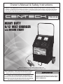
Owner’s Manual & Safety Instructions
Save This Manual Keep this manual for the safety warnings and precautions, assembly, operating,
inspection, maintenance and cleaning procedures. Write the product’s serial number in the back of the manual
near the assembly diagram (or month and year of purchase if product has no number). Keep this manual and
the receipt in a safe and dry place for future reference.
ITEM 69368
HEAVY DUTY
6/12 VOLT CHARGER
with ENGINE
START
Visit our website at: http://www.harborfreight.com
Email our technical support at: [email protected]
When unpacking, make sure that the product is intact
and undamaged. If any parts are missing or broken,
please call 1-800-444-3353 as soon as possible.
Copyright© 2011 by Harbor Freight Tools®. All rights reserved.
No portion of this manual or any artwork contained herein may be reproduced in
any shape or form without the express written consent of Harbor Freight Tools.
Diagrams within this manual may not be drawn proportionally. Due to continuing
improvements, actual product may differ slightly from the product described herein.
Tools required for assembly and service may not be included.
Read this material before using this product.
Failure to do so can result in serious injury.
SAVE THIS MANUAL.
Table of Contents
SAFETY
Safety.......................................................... 2
Specifications.............................................. 6
Assembly..................................................... 6
Operation..................................................... 7
Maintenance............................................... 10
Parts List and Diagram............................... 11
Warranty..................................................... 12
WARNING SYMBOLS AND DEFINITIONS
ASSEMBLY
This is the safety alert symbol. It is used to alert you to potential personal injury hazards.
Obey all safety messages that follow this symbol to avoid possible injury or death.
Indicates a hazardous situation which, if not avoided,
will result in death or serious injury.
Indicates a hazardous situation which, if not avoided,
could result in death or serious injury.
Indicates a hazardous situation which, if not avoided,
could result in minor or moderate injury.
Addresses practices not related to personal injury.
OPERATION
Canadian Standards Association
Underwriters Laboratories, Inc.
MAINTENANCE
V~
A
CCA
RC
Ah
Page 2
Volts Alternating Current
Amperes
Cold Cranking Amps
WARNING marking
concerning Risk of Eye Injury.
Wear ANSI‑approved
splash‑resistant safety goggles.
Read the manual before
set-up and/or use.
WARNING marking
concerning Risk of Fire.
Follow connection procedure.
Reserve Capacity
Ampere-hours
For technical questions, please call 1-800-444-3353.
Item 69368
9. To reduce risk of electric shock, unplug charger
from outlet before attempting any maintenance or
cleaning. Turning off controls will not reduce this risk.
2. Do not expose charger to rain or snow.
10. WARNING – RISK OF EXPLOSIVE GASES.
a. WORKING IN VICINITY OF A LEAD-ACID
BATTERY IS DANGEROUS. BATTERIES
GENERATE EXPLOSIVE GASES DURING
NORMAL BATTERY OPERATION. FOR THIS
REASON, IT IS OF UTMOST IMPORTANCE
THAT YOU FOLLOW THE INSTRUCTIONS
EACH TIME YOU USE THE CHARGER.
3. Use of an attachment not recommended or sold
by the battery charger manufacturer may result in
a risk of fire, electric shock, or injury to persons.
4. To reduce risk of damage to electric
plug and cord, pull by plug rather than
cord when disconnecting charger.
5. An extension cord should not be used unless
absolutely necessary. Use of improper extension
cord could result in a risk of fire and electric shock.
If an extension cord must be used, make sure:
a. That pins on plug of extension cord
are the same number, size, and shape
as those of plug on charger;
11. PERSONAL PRECAUTIONS
a. Consider having someone close
enough by to come to your aid when
you work near a lead-acid battery.
b. That extension cord is properly wired
and in good electrical condition; and
c. That wire size is large enough for AC ampere
rating of charger as specified in Table A.
b. Have plenty of fresh water and soap nearby in
case battery acid contacts skin, clothing, or eyes.
Length of cord, feet
Equal to or
greater than
But less
than
25
50
8
10
18
14
12
10
10
12
16
14
10
8
12
14
16
12
10
8
14
16
16
12
10
8
16
18
14
12
8
8
18
20
14
12
8
6
100 150
* If the input rating of a charger is given in watts rather than in
amperes, the corresponding ampere rating is to be determined by
dividing the wattage rating by the voltage rating – for example:
1250 watts/125 volts = 10 amperes
6. Do not operate charger with damaged cord or plug
– replace the cord or plug immediately.
7. Do not operate charger if it has received a sharp
blow, been dropped, or otherwise damaged in
any way; take it to a qualified serviceman.
8. Do not disassemble charger; take it to a
qualified serviceman when service or repair
is required. Incorrect reassembly may
result in a risk of electric shock or fire.
Item 69368
d. If battery acid contacts skin or clothing,
wash immediately with soap and water.
If acid enters eye, immediately flood eye with
running cold water for at least 10 minutes
and get medical attention immediately.
e. NEVER smoke or allow a spark or flame
in vicinity of battery or engine.
f. Be extra cautious to reduce risk of dropping
a metal tool onto battery. It might spark
or short-circuit battery or other electrical
part that may cause explosion.
OPERATION
AWG size of cord
c. Wear complete eye protection and
clothing protection. Avoid touching
eyes while working near battery.
g. Remove personal metal items such as rings,
bracelets, necklaces, and watches when working
with a lead-acid battery. A lead-acid battery can
produce a short-circuit current high enough to weld
a ring or the like to metal, causing a severe burn.
h. Use charger for charging a LEAD-ACID battery
only. It is not intended to supply power to a
low voltage electrical system other than in a
starter-motor application. Do not use battery
charger for charging dry-cell batteries that
are commonly used with home appliances.
These batteries may burst and cause injury
to persons and damage to property.
i. NEVER charge a frozen battery.
For technical questions, please call 1-800-444-3353.
Page 3
MAINTENANCE
Table A: Recommended minimum AWG size
for extension cords for battery chargers
AC input rating, amperes*
b. To reduce risk of battery explosion, follow
these instructions and those published by
battery manufacturer and manufacturer of
any equipment you intend to use in vicinity
of battery. Review cautionary marking
on these products and on engine.
ASSEMBLY
1. SAVE THESE INSTRUCTIONS –
This manual contains important safety and
operating instructions for this battery charger.
SAFETY
IMPORTANT SAFETY INSTRUCTIONS
12. PREPARING TO CHARGE
d. Determine which post of battery is grounded
(connected) to the chassis. If negative post is
grounded to chassis (as in most vehicles), see (e).
If positive post is grounded to the chassis, see (f).
a. If necessary to remove battery from vehicle
to charge, always remove grounded terminal
from battery first. Make sure all accessories in
the vehicle are off, so as not to cause an arc.
SAFETY
e. For negative-grounded vehicle, connect
POSITIVE (RED) clip from battery charger to
POSITIVE (POS, P, +) ungrounded post of
battery. Connect NEGATIVE (BLACK) clip to
vehicle chassis or engine block away from battery.
Do not connect clip to carburetor, fuel lines, or
sheet-metal body parts. Connect to a heavy
gauge metal part of the frame or engine block.
b. Be sure area around battery is well
ventilated while battery is being charged.
c. Clean battery terminals. Be careful to keep
corrosion from coming in contact with eyes.
d. Add distilled water in each cell until battery
acid reaches level specified by battery
manufacturer. Do not overfill. For a battery
without removable cell caps, such as valve
regulated lead acid batteries, carefully follow
manufacturer’s recharging instructions.
f. For positive-grounded vehicle, connect
NEGATIVE (BLACK) clip from battery charger
to NEGATIVE (NEG, N, –) ungrounded post of
battery. Connect POSITIVE (RED) clip to vehicle
chassis or engine block away from battery.
Do not connect clip to carburetor, fuel lines, or
sheet-metal body parts. Connect to a heavy
gauge metal part of the frame or engine block.
e. Study all battery manufacturer’s
specific precautions while charging and
recommended rates of charge.
ASSEMBLY
f. Determine voltage of battery by referring to vehicle
owner’s manual and make sure it matches output
rating of battery charger. If charger has adjustable
charge rate, charge battery initially at lowest rate.
g. When disconnecting charger, turn
switches to off, disconnect AC cord,
remove clip from vehicle chassis, and then
remove clip from battery terminal.
13. CHARGER LOCATION
a. Locate charger as far away from
battery as DC cables permit.
b. Never place charger directly above
battery being charged; gases from battery
will corrode and damage charger.
c. Never allow battery acid to drip on charger when
reading electrolyte specific gravity or filling battery.
h. See operating instructions for
length of charge information.
16. FOLLOW THESE STEPS WHEN BATTERY
IS OUTSIDE VEHICLE. A SPARK NEAR THE
BATTERY MAY CAUSE BATTERY EXPLOSION.
TO REDUCE RISK OF A SPARK NEAR BATTERY:
OPERATION
a. Check polarity of battery posts. POSITIVE
(POS, P, +) battery post usually has a larger
diameter than NEGATIVE (NEG, N, –) post.
d. Do not operate charger in a closed-in
area or restrict ventilation in any way.
b. Attach at least a 24-inch-long 6-gauge
(AWG) insulated battery cable to
NEGATIVE (NEG, N, –) battery post.
e. Do not set a battery on top of charger.
14. DC CONNECTION PRECAUTIONS
c. Connect POSITIVE (RED) charger clip to
POSITIVE (POS, P, +) post of battery.
a. Connect and disconnect DC output clips only
after setting any charger switches to “off” position
and removing AC cord from electric outlet.
Never allow clips to touch each other.
d. Position yourself and free end of cable
as far away from battery as possible
– then connect NEGATIVE (BLACK)
charger clip to free end of cable.
b. Attach clips to battery and chassis as indicated
in 15(e), 15(f), and 16(b) through 16(d).
e. Do not face battery when making final connection.
MAINTENANCE
15. FOLLOW THESE STEPS WHEN BATTERY
IS INSTALLED IN VEHICLE. A SPARK NEAR
BATTERY MAY CAUSE BATTERY EXPLOSION.
TO REDUCE RISK OF A SPARK NEAR BATTERY:
f. When disconnecting charger, always do
so in reverse sequence of connecting
procedure and break first connection while
as far away from battery as practical.
a. Position AC and DC cords to reduce risk of
damage by hood, door, or moving engine part.
b. Stay clear of fan blades, belts, pulleys, and
other parts that can cause injury to persons.
c. Check polarity of battery posts. POSITIVE
(POS, P, +) battery post usually has larger
diameter than NEGATIVE (NEG, N,–) post.
Page 4
g. A marine (boat) battery must be removed and
charged on shore. To charge it on board requires
equipment specially designed for marine use.
17.
Wear ANSI-approved splash-resistant
safety goggles and heavy-duty rubber
work gloves whenever connecting,
disconnecting, or working near battery.
Battery acid can cause
permanent blindness.
For technical questions, please call 1-800-444-3353.
Item 69368
19. This product is not a toy.
Keep it out of reach of children.
27. Before moving charger, disconnect power supply
and battery, then allow charger to cool.
20. Unplug the Battery Charger from its
electrical outlet before connecting its cables
to a battery, or performing any inspection,
maintenance, or cleaning procedures.
28. People with pacemakers should consult their
physician(s) before use. Electromagnetic fields in
close proximity to heart pacemaker could cause
pacemaker interference or pacemaker failure.
In addition, people with pacemakers should:
• Avoid operating alone.
• Properly maintain and inspect to avoid
electrical shock.
• Properly ground power cord. Ground Fault Circuit
Interrupter (GFCI) should also be implemented
– it prevents sustained electrical shock.
21. This Charger/Starter does NOT have an automatic
cut off. It is equipped with a timer. Check battery
and time manually; do NOT depend solely on
timer. Leaving Charger/Starter unattended
can result in fire and property damage.
22. Use this Battery Charger with flooded
lead‑acid batteries only. When charging a
maintenance‑free battery, always monitor the
progress of the charge by viewing the ammeter.
Do not overcharge a maintenance-free battery.
23. Do not attempt to charge non‑rechargeable
or defective batteries.
24. Do not charge more than one battery at one time.
25. Have your charger serviced by a qualified repair
person using only identical replacement parts.
This will ensure that the safety of
the charger is maintained.
29. WARNING: Handling the cord on this product will
expose you to lead, a chemical known to the State of
California to cause cancer, and birth defects or other
reproductive harm. Wash hands after handling.
(California Health & Safety Code § 25249.5, et seq.)
30. The warnings, precautions, and instructions
discussed in this instruction manual cannot
cover all possible conditions and situations
that may occur. It must be understood by the
operator that common sense and caution are
factors which cannot be built into this product,
but must be supplied by the operator.
OPERATION
SAVE THESE INSTRUCTIONS.
Grounding and AC Power Cord Connection Instructions
Item 69368
DANGER – Never alter AC cord or plug provided
– if it will not fit outlet, have proper outlet installed
by a qualified electrician. Improper connection
can result in a risk of an electric shock.
CAUTION – Risk of Fire or Electric Shock.
Connect battery charger directly to grounding
receptacle (three-prong). An adapter should
not be used with battery charger.
For technical questions, please call 1-800-444-3353.
MAINTENANCE
Charger should be grounded to reduce risk of electric
shock. Charger is equipped with an electric cord
having an equipment-grounding conductor and a
grounding plug. The plug must be plugged into an
outlet that is properly installed and grounded in
accordance with all local codes and ordinances.
SAFETY
26. Do not use charger while you are tired or under
the influence of drugs, alcohol or medication.
A moment of inattention while operating charger
may result in serious personal injury.
ASSEMBLY
18. Maintain labels and nameplates on the charger.
These carry important safety information.
If unreadable or missing, contact
Harbor Freight Tools for a replacement.
Page 5
Specifications
Electrical Rating
SAFETY
Charge Settings
Starter Settings
Battery Cables
120V~ / 60Hz / 9A
@ 40A, 12V Setting
2A, 12V
10A, 12V
40A, 12V
100A, 6V
60 second maximum with 90 second minimum rest
200A, 12V
5 second maximum with 240 second minimum rest
6' 6"
Red = Positive
Black = Negative
Power Cord
6' 5"
Timer Settings
0-180 minutes (up to 3 hours), and continuous (HOLD)
ASSEMBLY
Assembly Instructions
Read the ENTIRE IMPORTANT SAFETY INFORMATION section at the beginning of this
manual including all text under subheadings therein before set up or use of this product.
TO PREVENT SERIOUS INJURY: Unplug the charger, disconnect any battery,
and allow charger to cool completely before assembling or making any adjustments to the charger.
Note: For additional information regarding the parts listed in the following pages,
refer to Parts List and Diagram on page 11.
1. Place the Battery Charger/Starter on its side.
OPERATION
2. Use two Screws (10) to install the
Mounting Foot (5) to the front bottom of
the Charger/Starter. See Figure A.
3. Slide the Wheels (3) onto the ends of the Axle (4)
and slide an Axle Cap (6) onto each wheel. If
needed, tap on the Axle Caps with a rubber mallet.
Wheel
(3)
Axle (4)
Axle
Bracket
(7)
Screws
(10)
NOTE: Verify the Hub of each Wheel is facing in.
4. Set the Axle along the bottom of the Charger/
Starter and Align the Axle Brackets (7) with
the mounting holes. Once aligned, fasten
the Wheel Axle into place. See Figure A.
Mounting
Foot (5)
Axle Cap (6)
Figure A: Foot and Wheel Installation
MAINTENANCE
5. Stand up the Charger/Starter.
Handle (2)
6. Remove the two top screws on each side of the
Charger/Starter and set the Handle against the
unit, aligning the mounting holes. See Figure B.
Screw (9)
7. Use the Screws (9) to mount the Handle (2) on the
sides of the Charger/Starter (1). See Figure B.
Charger/
Starter (1)
Figure B: Handle Installation
Page 6
For technical questions, please call 1-800-444-3353.
Item 69368
Operating Instructions
Read the ENTIRE IMPORTANT SAFETY INFORMATION section at the beginning of this
manual including all text under subheadings therein before set up or use of this product.
SAFETY
TO PREVENT SERIOUS INJURY:
Assemble charger according to Assembly Instructions before use.
DO NOT PLUG IN CHARGER UNTIL DIRECTED TO DO SO.
Controls
Ammeter: The ammeter indicates amount of current
measured in amperes that is drawn from battery.
For example, in 40 amp charge rate a typical discharged
battery will initially draw approximately 40 amps.
As battery continues to charge, current will taper to
15 to 20 amps at full charge. When cranking an engine,
starter motor draws up to 200 amps. The meter needle
will register to extreme left side during 2 amp charge
rate, indicating minimal activity because the meter
doesn’t have the resolution to display such low rates.
Timer Dial
Setting Dial
Figure C: Controls
Timer Dial: The Timer prevents over-charging while
allowing a battery the needed time to obtain a satisfactory
charge. To set the Timer, you must know the size of
battery in ampere hours or reserve capacity in minutes,
and the state of charge. The state of charge can be
obtained using a battery load tester (not included).
For example, the average size automotive battery at 50%
charge will require 1 to 1-1/2 hours of charging at 40
amp rate to reach full charge state. For the same battery
with the Timer set to maximum, overcharging will occur.
Slight overcharging should not harm a battery that was
otherwise in good condition. When the state of charge is
unknown, start out with a timer setting of one hour or less.
Hold: (on Timer Dial) This sets the charger for
continuous operation. Use for long-period charging,
such as when the lowest charge rate is selected.
WARNING! TO PREVENT SERIOUS INJURY
AND FIRE: Monitor charging and stop
charge when battery is fully charged.
Item 69368
When a battery is close to being dead or has a
very low charge, it will want to draw more current.
When a dead or low battery is charged, the charger’s
ammeter will register at high end. As the battery charges,
the reading will move down toward the low end,
resting on zero, when battery is fully charged.
Do not depend on reading ammeter to approximate
how long charging will take. Even at full charge,
ammeter will still provide as much as 50% of charger’s
output rating. Sometimes conditions such as a cold
battery, a sulfated battery, or a deeply discharged
Lead Calcium battery may cause ammeter to read near
a full charge when charging process is only beginning.
Note: The ammeter shows the amount of current
being drawn from the charger. It does not
show what the charger is capable of delivering.
When the battery is fully charged and registering
zero on the ammeter, a small charge will continue to
move from the charger to the battery. If the charger
is not disconnected from the battery, eventually
heat build up will cause the battery acid to boil and
overcharge the battery causing damage to the battery.
Monitor battery charging progress constantly and if
battery gets warm, stop charging it immediately.
For technical questions, please call 1-800-444-3353.
Page 7
ASSEMBLY
Setting Dial: Use this to set the
voltage/amperage output.
OPERATION
Ammeter
MAINTENANCE
Voltmeter
Preparing to Charge
SAFETY
Use this charger only on flooded lead-acid batteries.
Other batteries may be damaged or may overheat, leak, or catch fire.
TO PREVENT SERIOUS INJURY:
Wear ANSI-approved splash-resistant safety goggles and heavy-duty rubber work gloves
whenever connecting, disconnecting, or working near battery.
Battery acid can cause permanent blindness.
1. If necessary to remove battery from vehicle to
charge, always remove grounded terminal from
battery first. Make sure all accessories in the
vehicle are off, so as not to cause an arc.
6. Determine voltage of battery by referring to vehicle
owner’s manual and make sure it matches output
rating of battery charger. If charger has adjustable
charge rate, charge battery initially at lowest rate.
2. Be sure area around battery is well ventilated
while battery is being charged.
7. A marine (boat) battery must be removed and
charged on shore. To charge it on board requires
equipment specially designed for marine use.
ASSEMBLY
3. Clean battery terminals. Be careful to keep
corrosion from coming in contact with eyes.
4. Add distilled water in each cell until battery acid
reaches level specified by battery manufacturer.
Do not overfill. For a battery without
removable cell caps, such as valve
regulated lead acid batteries, carefully follow
manufacturer’s recharging instructions.
5. Study all battery manufacturer’s specific precautions
while charging and recommended rates of charge.
SHORTED BATTERIES - will read on ammeter as
a high end peg at beginning of charging process.
If after 5-10 minutes, needle does not move off
high end, the battery probably has a short circuit.
Unplug charger and discontinue use.
Have battery checked by a qualified technician.
COLD BATTERIES - begin charging at a low rate,
increase as battery reaches a normal temperature,
then rate will decrease normally.
DO NOT CHARGE A FROZEN BATTERY.
BATTERIES WITH HYDROMETER EYE: Do not depend
on hydrometer eye to determine battery charge level.
OPERATION
Charger Location
1. Locate charger as far away from
battery as DC cables permit.
3. Never allow battery acid to drip on charger when
reading electrolyte specific gravity or filling battery.
2. Never place charger directly above battery
being charged; gases from battery will
corrode and damage charger.
4. Do not operate charger in a closed-in area
or restrict ventilation in any way.
5. Do not set a battery on top of charger.
MAINTENANCE
Table B: CHARGING RATE/TIME
Charge Rate
Battery Size / Rating
Charging Time (based on battery at 50% charge)
Small batteries
(Motorcycle, Garden Tractor, etc.)
200-315 CCA
Cars / Trucks
315-550 CCA
550-875 CCA
2A, 12V
6-12 Ah
40-60 RC
60-85 RC
85-125 RC
3~6 hr
13~20 hr
20~35 hr
35~55 hr
10A, 12V
40A, 12V
Do not use these rates
for small batteries.
2-1/2~4 hr
1/2~3/4 hr
4~7 hr
3/4~2 hr
7~11 hr
2~3 hr
WARNING! TO PREVENT SERIOUS INJURY, FIRE, AND PROPERTY DAMAGE:
Monitor charging during use. This Charger/Starter is not automatic and
can overcharge and damage a battery if allowed to operate for extended periods of time.
Page 8
For technical questions, please call 1-800-444-3353.
Item 69368
Charging Battery Installed in Vehicle
TO PREVENT SERIOUS INJURY:
Wear ANSI-approved splash-resistant safety goggles and heavy-duty rubber work gloves
whenever connecting, disconnecting, or working near battery.
Battery acid can cause permanent blindness.
2. Stay clear of fan blades, belts, pulleys, and
other parts that can cause injury to persons.
3. Check polarity of battery posts. POSITIVE
(POS, P, +) battery post usually has larger
diameter than NEGATIVE (NEG, N,–) post.
4. Determine which post of battery is grounded
(connected) to the chassis. If negative post is
grounded to chassis (as in most vehicles), see 5.
If positive post is grounded to the chassis, see 6.
5. For negative-grounded vehicle, connect
POSITIVE (RED) clip from battery charger to
POSITIVE (POS, P, +) ungrounded post of battery.
Connect NEGATIVE (BLACK) clip to vehicle
chassis or engine block away from battery.
Do not connect clip to carburetor, fuel lines, or
sheet-metal body parts. Connect to a heavy
gauge metal part of the frame or engine block.
6. For positive-grounded vehicle, connect
NEGATIVE (BLACK) clip from battery charger
to NEGATIVE (NEG, N, –) ungrounded post of
battery. Connect POSITIVE (RED) clip to vehicle
chassis or engine block away from battery.
Do not connect clip to carburetor, fuel lines, or
sheet-metal body parts. Connect to a heavy
gauge metal part of the frame or engine block.
7. When disconnecting charger, turn switches to
off, disconnect AC cord, remove clip from vehicle
chassis, and then remove clip from battery terminal.
8. See Table B on page 8 for
length of charge information.
9. After use clean, then store the charger
indoors out of children’s reach.
OPERATION
1. Position AC and DC cables to reduce risk of
damage by hood, door, or moving engine part.
ASSEMBLY
SAFETY
A SPARK NEAR BATTERY MAY CAUSE BATTERY EXPLOSION.
TO REDUCE RISK OF A SPARK NEAR BATTERY FOLLOW THESE INSTRUCTIONS EXACTLY.
Charging Battery Outside Vehicle
A SPARK NEAR BATTERY MAY CAUSE BATTERY EXPLOSION.
TO REDUCE RISK OF A SPARK NEAR BATTERY FOLLOW THESE INSTRUCTIONS EXACTLY.
TO PREVENT SERIOUS INJURY:
Wear ANSI-approved splash-resistant safety goggles and heavy-duty rubber work gloves
whenever connecting, disconnecting, or working near battery.
Battery acid can cause permanent blindness.
2. Attach at least a 24-inch-long 6-gauge
(AWG) insulated battery cable to
NEGATIVE (NEG, N, –) battery post.
3. Connect POSITIVE (RED) charger clip to
POSITIVE (POS, P, +) post of battery.
4. Position yourself and free end of cable as far away
from battery as possible – then connect NEGATIVE
(BLACK) charger clip to free end of cable.
Item 69368
5. Do not face battery when making final connection.
6. When disconnecting charger, always do
so in reverse sequence of connecting
procedure and break first connection while
as far away from battery as practical.
MAINTENANCE
1. Check polarity of battery posts. POSITIVE
(POS, P, +) battery post usually has a larger
diameter than NEGATIVE (NEG, N, –) post.
7. See Table B on page 8 for
length of charge information.
8. After use clean, then store the charger
indoors out of children’s reach.
For technical questions, please call 1-800-444-3353.
Page 9
Engine Starting
SAFETY
Some vehicles with onboard computers may be damaged from the high-current starting output.
Thoroughly read the vehicle service manual before using this procedure.
Note: During extremely cold weather or when battery
is severely exhausted, charge the battery for about
five minutes before attempting to turn on engine.
6. WARNING! TO PREVENT SERIOUS INJURY,
FIRE, AND DAMAGE TO STARTER AND BATTERY,
follow duty cycle for each Start mode as follows:
1. Set the charge rate and timer to the OFF positions.
100A, 6V:
60 second maximum with 90 second minimum rest
2. Plug the Charger AC power cord into the AC outlet.
200A, 12V:
5 second maximum with 240 second minimum rest
3. Set the Volt/Amp selector to the correct setting.
Make sure setting of Engine Start charge
rate matches the vehicle battery.
ASSEMBLY
4. For negative-grounded vehicle, connect
POSITIVE (RED) clip from battery charger to
POSITIVE (POS, P, +) ungrounded post of battery.
Connect NEGATIVE (BLACK) clip to vehicle
chassis or engine block away from battery.
Do not connect clip to carburetor, fuel lines, or
sheet-metal body parts. Connect to a heavy
gauge metal part of the frame or engine block.
5. Position AC and DC cables to reduce risk of
damage by hood, door, or moving engine part.
7. To start the engine, set the charge time dial to HOLD
and turn ignition key. ONLY KEEP CHARGER
IN START MODE AS LONG AS THE DUTY
CYCLE LISTED ABOVE ALLOWS.
Note: If the unit beeps, the cables are reversed or
touching (short-circuited) and the Engine Starter will
power off. Check that cables are connected properly.
8. If engine fails to start, charge battery for an
additional five minutes before attempting to start.
9. After the engine starts, move the charge rate
switch to OFF and unplug the power cord from
outlet before disconnecting the DC cable clamps.
Maintenance Instructions
OPERATION
Procedures not specifically explained in this manual must
be performed only by a qualified technician.
TO PREVENT SERIOUS INJURY: Unplug the charger, disconnect any battery, and allow charger
to cool completely before performing any inspection, maintenance, or cleaning procedures.
TO PREVENT SERIOUS INJURY FROM TOOL FAILURE:
Do not use damaged equipment. If abnormal noise or vibration occurs,
have the problem corrected before further use.
MAINTENANCE
1. BEFORE EACH USE, inspect the general condition
of the charger. Check for loose hardware,
misalignment or binding of moving parts, cracked
or broken parts, damaged electrical wiring, and any
other condition that may affect its safe operation.
3.
WARNING! If the supply cord of this
charger is damaged, it must be replaced
only by a qualified service technician.
DO NOT OPEN CHARGER HOUSING,
NO USER-SERVICEABLE PARTS INSIDE.
2. AFTER USE, wipe external surfaces
of the tool with clean cloth.
Page 10
For technical questions, please call 1-800-444-3353.
Item 69368
Troubleshooting
3. Defective battery.
4. Charge Engine Starter is resetting
itself after circuit overload.
5. Circuit breaker is cycling.
Likely Solutions
Check or replace battery.
1. Check power and cable outlet connections.
2. Clean battery cables and reset cable clamps.
3. None, meter will not indicate at this rate.
1. Continue charging battery.
2. Check and/or replace battery.
1. Double-check connection polarity.
If wrong, shut off charger and correct
cable lead connections.
2. Continue charging battery.
Charger will continue to reset itself until
the battery reaches a chargeable level.
3. Check and/or replace battery.
4. Wait until Charger automatically resets itself.
5. May be the wrong switch position.
Follow all safety precautions whenever diagnosing or servicing the tool.
Disconnect power supply before service.
SAFETY
Possible Causes
ASSEMBLY
Problem
Ammeter display
Defective battery.
reads maximum.
No ammeter reading. 1. No power to engine starter.
2. Battery cables not making connection.
3. Two-amp charge rate being used.
Charging current
1. Battery is partially charged.
not to full output.
2. Defective battery, will not
hold full charge.
Ammeter needle
1. Reversed battery connections.
moves up to full
charge, then drops
to zero. Makes
2. Battery is completely dead.
“clicking” noise.
Parts List and Diagram
1
2
3
4
5
Description
Qty
Battery Charger
Handle
Wheels
Axle
Mounting Foot
1
1
2
1
1
Part
6
7
8
9
10
Description
Qty
Axle Caps
Axle Brackets
Snap Ring
Screw (5x28mm)
Screw (5x13mm)
2
2
2
4
6
4
8
10
10
3
2
OPERATION
Part
9
1
MAINTENANCE
6
1
5
7
Record Product’s Serial Number Here:
Note: If product has no serial number, record month and year of purchase instead.
Note: Some parts are listed and shown for illustration purposes only, and are not available individually
as replacement parts. Internal parts are not user-serviceable and are not available.
Item 69368
For technical questions, please call 1-800-444-3353.
Page 11
PLEASE READ THE FOLLOWING CAREFULLY
THE MANUFACTURER AND/OR DISTRIBUTOR HAS PROVIDED THE PARTS LIST AND ASSEMBLY DIAGRAM
IN THIS MANUAL AS A REFERENCE TOOL ONLY. NEITHER THE MANUFACTURER OR DISTRIBUTOR
MAKES ANY REPRESENTATION OR WARRANTY OF ANY KIND TO THE BUYER THAT HE OR SHE IS
QUALIFIED TO MAKE ANY REPAIRS TO THE PRODUCT, OR THAT HE OR SHE IS QUALIFIED TO REPLACE
ANY PARTS OF THE PRODUCT. IN FACT, THE MANUFACTURER AND/OR DISTRIBUTOR EXPRESSLY
STATES THAT ALL REPAIRS AND PARTS REPLACEMENTS SHOULD BE UNDERTAKEN BY CERTIFIED AND
LICENSED TECHNICIANS, AND NOT BY THE BUYER. THE BUYER ASSUMES ALL RISK AND LIABILITY
ARISING OUT OF HIS OR HER REPAIRS TO THE ORIGINAL PRODUCT OR REPLACEMENT PARTS
THERETO, OR ARISING OUT OF HIS OR HER INSTALLATION OF REPLACEMENT PARTS THERETO.
Limited 90 Day Warranty
Harbor Freight Tools Co. makes every effort to assure that its products meet high quality and durability standards,
and warrants to the original purchaser that this product is free from defects in materials and workmanship for the
period of 90 days from the date of purchase. This warranty does not apply to damage due directly or indirectly,
to misuse, abuse, negligence or accidents, repairs or alterations outside our facilities, criminal activity, improper
installation, normal wear and tear, or to lack of maintenance. We shall in no event be liable for death, injuries
to persons or property, or for incidental, contingent, special or consequential damages arising from the use of
our product. Some states do not allow the exclusion or limitation of incidental or consequential damages, so the
above limitation of exclusion may not apply to you. THIS WARRANTY IS EXPRESSLY IN LIEU OF ALL OTHER
WARRANTIES, EXPRESS OR IMPLIED, INCLUDING THE WARRANTIES OF MERCHANTABILITY AND FITNESS.
To take advantage of this warranty, the product or part must be returned to us with transportation charges
prepaid. Proof of purchase date and an explanation of the complaint must accompany the merchandise.
If our inspection verifies the defect, we will either repair or replace the product at our election or we may
elect to refund the purchase price if we cannot readily and quickly provide you with a replacement. We will
return repaired products at our expense, but if we determine there is no defect, or that the defect resulted
from causes not within the scope of our warranty, then you must bear the cost of returning the product.
This warranty gives you specific legal rights and you may also have other rights which vary from state to state.
3491 Mission Oaks Blvd. • PO Box 6009 • Camarillo, CA 93011 • (800) 444-3353