1
R
GRANITE MIDI LATHE
Model Number
60100G
(Variable Speed)
Model Number
60170G
(5-Speed)
STEEL CITY TOOL WORKS
VER. 12.08
Manual Part No. OR71666
R
d
d
d
d
d
2
TABLE OF CONTENTS
INTRODUCTION
SECTION 1
Warranty .................................................................................................................................................4
SECTION 2
Product Specifications ............................................................................................................................7
SECTION 3
Accessories and Attachments ................................................................................................................8
SECTION 4
Definition of Terms ..................................................................................................................................8
SECTION 5
Feature Identification ..............................................................................................................................9
SECTION 6
General Safety ......................................................................................................................................11
SECTION 7
Product Safety ......................................................................................................................................13
SECTION 8
Electrical Requirements........................................................................................................................15
SECTION 9
Unpacking & Inventory..........................................................................................................................17
SECTION 10
Assembly ..............................................................................................................................................19
SECTION 11
Adjustments ..........................................................................................................................................20
SECTION 12
Operations ............................................................................................................................................25
SECTION 13
Maintenance .........................................................................................................................................26
SECTION 14
Troubleshooting ....................................................................................................................................28
SECTION 15
Parts List...............................................................................................................................................30
INTRODUCTION
This user manual is intended for use by anyone working with this machine. It should be kept available
for immediate reference so that all operations can be performed with maximum efficiency and safety.
Do not attempt to perform maintenance or operate this machine until you have read and understand the
information contained in this manual.
The drawings, illustrations, photographs, and specifications in this user manual represent your machine
at time of print. However, changes may be made to your machine or this manual at any time with no
obligation to Steel City Tool Works.
3
WARRANTY
STEEL CITY TOOLWORKS
5 YEAR LIMITED WARRANTY
Steel City Tool Works, LLC ("SCTW") machinery to be free of defects in workmanship and
materials for a period of 5 years from the date of the original retail purchase by the original
owner. (Granite components are warranted for 10 years. See the Granite warranty statement
supplied with those products.) SCTW will repair or replace, at its expense and at its option,
any SCTW machine, machine part, or machine accessory which in normal use has proven to
be defective, provided that the customer returns the product, shipping prepaid, to an
authorized service center with proof of purchase and provides SCTW with a reasonable
opportunity to verify the alleged defect by inspection. This warranty does not apply to defects
due directly or indirectly to misuse, abuse, negligence, accidents, or lack of maintenance, or to
repairs or alterations made or specifically authorized by anyone other than SCTW. Normal
wear components are also excluded under this coverage. Every effort has been made to ensure
that all SCTW machinery meets the highest quality and durability standards. We reserve the
right to change specifications at any time due to our commitment to continuous improvement
of the quality of our products.
EXCEPT AS SET FORTH ABOVE, SCTW MAKES NO EXPRESS OR IMPLIED
REPRESENTATIONS OR WARRANTIES WITH RESPECT TO ITS MACHINERY, OR ITS
CONDITION, MERCHANTABILITY, OR FITNESS FOR ANY PARTICULAR PURPOSE
OR USE. SCTW FURNISHES THE ABOVE WARRANTIES IN LIEU OF ALL OTHER
WARRANTIES, EXPRESS OR IMPLIED, INCLUDING THE WARRANTIES OF
MERCHANTABILITY AND FITNESS FOR A PARTICULAR PURPOSE, WHICH ARE
HEREBY SPECIFICALLY DISCLAIMED.
SCTW SHALL NOT BE LIABLE FOR ANY (A) SPECIAL, INDIRECT, INCIDENTAL,
PUNITIVE OR CONSEQUENTIAL DAMAGES, INCLUDING WITHOUT LIMITATION
LOSS OF PROFITS, ARISING FROM OR RELATED TO THIS WARRANTY, THE
BREACH OF ANY AGREEMENT OR WARRANTY, OR THE OPERATION OR USE OF
ITS MACHINERY, INCLUDING WITHOUT LIMITATION DAMAGES ARISING FROM
DAMAGE TO FIXTURES, TOOLS, EQUIPMENT, PARTS OR MATERIALS, DIRECT OR
INDIRECT LOSS CAUSED BY ANY OTHER PARTY, LOSS OF REVENUE OR PROFITS,
FINANCING OR INTEREST CHARGES, AND CLAIMS BY ANY THIRD PERSON,
WHETHER OR NOT NOTICE OF SUCH POSSIBLE DAMAGES HAS BEEN GIVEN TO
SCTW; (B) DAMAGES OF ANY KIND FOR ANY DELAY BY OR FAILURE OF SCTWTO
PERFORM ITS OBLIGATIONS UNDER THIS AGREEMENT; OR (C) CLAIMS MADE A
SUBJECT OF A LEGAL PROCEEDING AGAINST SCTW MORE THAN ONE (1) YEAR
AFTER SUCH CAUSE OF ACTION FIRST AROSE.
The validity, construction and performance of this Warranty and any sale of machinery by
SCTW shall be governed by the laws of the Commonwealth of Pennsylvania, without regard
to conflicts of laws provisions of any jurisdiction. Any action related in any way to any alleged
or actual offer, acceptance or sale by SCTW, or any claim related to the performance of any
agreement including without limitation this Warranty, shall take place in the federal or state
courts in Allegheny County, Pennsylvania.
4
WARRANTY CARD
Name ________________________________________________
Street _______________________________________________
Apt. No. ______________________________________________
City _________________________ State ______ Zip __________
Phone Number_________________________________________
E-Mail ________________________________________________
The following information is given on a voluntary basis
and is strictly confidential.
Where did you purchase your STEEL CITY machine?
Store: ____________________________________________
City:______________________________________________
2.
How did you first learn of Steel City Tool Works?
___ Advertisement
___ Mail Order Catalog
___ Web Site
___ Friend
___ Local Store
Other_______________________
! CUT HERE
3.
4.
5.
6.
7.
Which of the following magazines
___ American Woodworker
––– Cabinetmaker
___ Fine Homebuilding
___ Journal of Light Construction
___ Popular Mechanics
___ Popular Woodworking
___ WOOD
___ WOODEN Boat
___ Woodsmith
___ Woodworker
___ Workbench
What is your age group?
___ 20 to 29 years
___ 40 to 49 years
___ 60 to 69 years
9.
How many Steel City machines do you own? _____________
11. Which benchtop tools do you own? Check all that apply.
___ Belt Sander
___ Belt / Disc Sander
___ Drill Press
___ Band Saw
___ Grinder
___ Mini Jointer
___ Mini Lathe
___ Scroll Saw
___ Spindle / Belt Sander
Other______________________
do you subscribe to?
___ American How-To
___ Family Handyman
___ Fine Woodworking
___ Old House Journal
___ Popular Science
___ Today’s Homeowner
___ Woodcraft
___ Woodshop News
___ Woodwork
___ Woodworker’s Journal
Other_________________
12. Which portable / hand held power tools do you own?
Check all that apply.
___ Belt Sander
___ Biscuit Jointer
___ Dust Collector
___ Circular Saw
___ Detail Sander
___ Drill / Driver
___ Miter Saw
___ Orbital Sander
___ Palm Sander
___ Portable Thickness Planer
___ Saber Saw
___ Reciprocating Saw
___ Router
Other_______________________
13. What machines / accessories would you like to see added to the
STEEL CITY line?
____________________________________________________
____________________________________________________
Which of the following woodworking / remodeling shows do
you watch?
___ Backyard America ___ The American Woodworker
___ Home Time
___ The New Yankee Workshop
___ This Old House
___ Woodwright’s Shop
Other__________________________________________
What is your annual household
___ $20,000 to $29,999
___ $40,000 to $49,999
___ $60,000 to $69,999
___ $80,000 to $89,999
How would you rank your woodworking skills?
___ Simple
___ Intermediate
___ Advance
___ Master Craftsman
10. What stationary woodworking tools do you own?
Check all that apply.
___ Air Compressor
___ Band Saw
___ Drill Press
___ Drum Sander
___ Dust Collection
___ Horizontal Boring Machine
___ Jointer
___ Lathe
___ Mortiser
___ Panel Saw
___ Planer
___ Power Feeder
___ Radial Arm Saw
___ Shaper
___ Spindle Sander
___ Table Saw
___ Vacuum Veneer Press
___ Wide Belt Sander
Other____________________________________________
Product Description:_____________________________________
Model No.: ___________________________________________
Serial No. _____________________________________________
1.
8.
14. What new accessories would you like to see added?
____________________________________________________
____________________________________________________
income?
___ $30,000 to $39,999
___ $50,000 to $59,999
___ 70,000 to $79,999
___ $90,000 +
15. Do you think your purchase represents good value?
___Yes
___ No
16. Would you recommend STEEL CITY products to a friend?
___ Yes
___ No
___ 30 to 39 years
___ 50 to 59 years
___ 70 + years
17. Comments:
____________________________________________________
____________________________________________________
____________________________________________________
____________________________________________________
____________________________________________________
How long have you been a woodworker?
___ 0 to 2 years
___ 2 to 8 years
___ 8 to 20 years
___ over 20 years
5
FOLD ON DOTTED LINE
PLACE
STAMP
HERE
Steel City Tool Works
3656 Enterprise Avenue Hayward,
CA 94545
FOLD ON DOTTED LINE
6
MOTOR
60100G Mini Lathe
60170G Mini Lathe
Variable Speed
5-Speed
Continuous Duty HP
1/2 HP
1/2 HP
Amps
3
5.6
Voltage
115V DC
115VAC
Phase
Single
Single
Hertz
60 Hz
60 Hz
RPM
500-3800
1725
Swing Over Bed
12”
12”
Swing Over Tool Rest Base
9-1/4”
9-1/4”
Working Distance Between Centers
27”
27”
SPECIFICATIONS
Range of Speeds (RPM)
500-1350, 1400-3800
500, 1300, 2100, 2750, 3600
Number of Speeds
N/A
5
Hole Through Spindle
3/8”
3/8”
Headstock Spindle Taper
#2 MT
#2 MT
Tailstock Spindle Taper
#2 MT
#2 MT
Hole Through Tailstock
3/8”
3/8”
Toolrest Length
6”
6”
Length
44”
44”
Width
10”
10”
Height
20-1/2”
20-1/2”
Net Weight
154 lbs.
158 lbs.
PRODUCT DIMENSIONS
SHIPPING DIMENSIONS
Carton Type
Length
Wooden Crate
Wooden Crate
45-1/2”
45-1/2”
Width
13”
13”
Height
24-1/2”
24-1/2”
187 lbs.
192 lbs.
Gross Weight
7
ACCESSORIES AND ATTACHMENTS
There are a variety of accessories available for your Steel City Product. For more information on
any accessories associated with this and other machines, please contact your nearest Steel City
distributor, or visit our website at: www.steelcitytoolworks.com.
DEFINITION OF TERMS
Banjo - The part on the lathe which slides along the
bed and supports the tool rest.
Headstock - The assembly fixed on the left-hand end
of the bed of the lathe which provides the drive for the
workpiece.
Bed - The horizontal part of the lathe which connects
the headstock and tailstock.
Tailstock - The movable assembly to the right of the
headstock which slides along the bed.
Chisel - A woodturning tool which is ground with a bevel.
Tool rest - Adjustable part of the lathe which fits into
the banjo and supports the turning tool while the work
is in progress.
Chuck - A device which holds the workpiece on the
lathe.
Faceplate - Fastens to the headstock and is used for
face turning operations such as making a bowl.
8
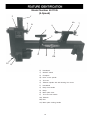
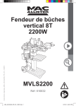
Model Number 60100G
(Variable Speed)
M
B
F
N
C
E
D
O
K
A
J
H
L
I
A)
Headstock
B)
Variable Speed Switch
C)
Faceplate
D)
Drive center spindle
E)
Tool rest
F)
Tailstock spindle with ball bearing live center
G)
Handwheel
H)
Banjo lock handle
I)
Motor plate lever
J)
Banjo
K)
Tool rest lock handle
L)
Motor plate locking handle
M) ON/OFF Switch
N)
Tailstock
O)
Bed
9
G
Model Number 60170G
(5-Speed)
Y
Z
X
AA
W
U
V
P
R
CC
S
BB
Q
Z)
Headstock
Y)
ON/OFF switch
X)
Faceplate
W) Drive center spindle
V)
Tool rest
U)
Tailstock spindle with ball bearing live center
T)
Handwheel
S)
Banjo lock handle
R)
Banjo
Q)
Motor plate lever
P)
Tool rest lock handle
AA) Tailstock
BB) Bed
CC) Motor plate locking handle
10
T
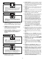
GENERAL SAFETY
!
!
WARNING
WARNING
TO AVOID serious injury and damage to the machine,
read and follow all Safety and Operating Instructions
before assembling and operating this machine.
This manual is not totally comprehensive. It does not
and can not convey every possible safety and operational problem which may arise while using this
machine. The manual will cover many of the basic and
specific safety procedures needed in an industrial environment.
Exposure to the dust created by power sanding, sawing, grinding, drilling and other construction activities
may cause serious and permanent respiratory or
other injury, including silicosis (a serious lung disease), cancer, and death. Avoid breathing the dust,
and avoid prolonged contact with dust. The dust
may contain chemicals known to the State of
California to cause cancer, birth defects or other
reproductive harm.
All federal and state laws and any regulations having
jurisdiction covering the safety requirements for use of
this machine take precedence over the statements in
this manual. Users of this machine must adhere to all
such regulations.
Some examples of these chemicals are:
• Lead from lead-based paints.
• Crystalline silica from bricks, cement and other
masonry products.
• Arsenic and chromium from chemically-treated
lumber.
Below is a list of symbols that are used to attract your
attention to possible dangerous conditions.
!
This is the safety alert symbol. It is used to alert you to
potential personal injury hazards. Obey all safety messages that follow this symbol to avoid possible injury or
death.
!
Always operate tool in well ventilated area and provide for proper dust removal. Use a dust collection
system along with an air filtration system whenever
possible. Always use properly fitting NIOSH/OSHA
approved respiratory protection appropriate for the
dust exposure, and wash exposed areas with soap
and water.
DANGER
Indicates an imminently hazardous situation which, if
not avoided, WILL result in death or serious injury.
!
1. To avoid serious injury and damage to the machine,
read the entire User Manual before assembly and
operation of this machine.
WARNING
Indicates a potentially hazardous situation which, if not
avoided, COULD result in death or serious injury.
!
CAUTION
!
WARNING
Indicates a potentially hazardous situation, if not avoided, MAY result in minor or moderate injury. It may also
be used to alert against unsafe practices.
CAUTION
2. ALWAYS wear eye protection. Any machine can
throw debris into the eyes during operations,
which could cause severe and permanent eye
damage. Everyday eyeglasses are NOT safety
glasses. ALWAYS wear Safety Goggles (that
comply with ANSI standard Z87.1) when operating power tools.
CAUTION used without the safety alert symbol indicates a potentially hazardous situation which, if not
avoided, may result in property damage.
NOTICE
This symbol is used to alert the user to useful information about proper operation of the machine.
11
!
11. DO NOT FORCE the machine to perform an operation for which it was not designed. It will do a safer
and higher quality job by only performing operations
for which the machine was intended.
WARNING
12. DO NOT stand on a machine. Serious injury could
result if it tips over or you accidentally contact any
moving part.
3. ALWAYS wear hearing protection. Plain cotton is
not an acceptable protective device. Hearing
equipment should comply with ANSI S3.19
Standards.
!
13. DO NOT store anything above or near the machine.
14. DO NOT operate any machine or tool if under the
influence of drugs, alcohol, or medication.
WARNING
15. EACH AND EVERY time, check for damaged parts
prior to using any machine. Carefully check all
guards to see that they operate properly, are not
damaged, and perform their intended functions.
Check for alignment, binding or breakage of all
moving parts. Any guard or other part that is damaged should be immediately repaired or replaced.
4. ALWAYS wear a NIOSH/OSHA approved dust
mask to prevent inhaling dangerous dust or airborne particles.
16. Ground all machines. If any machine is supplied
with a 3-prong plug, it must be plugged into a 3contact electrical receptacle. The third prong is
used to ground the tool and provide protection
against accidental electric shock. DO NOT remove
the third prong.
5. ALWAYS keep the work area clean, well lit, and
organized. DO NOT work in an area that has slippery floor surfaces from debris, grease, and wax.
6. ALWAYS unplug the machine from the electrical
receptacle when making adjustments, changing
parts or performing any maintenance.
17. Keep visitors and children away from any machine.
DO NOT permit people to be in the immediate work
area, especially when the machine is operating.
7. AVOID ACCIDENTAL STARTING. Make sure that
the power switch is in the “OFF” position before
plugging in the power cord to the electrical
receptacle.
!
18. KEEP protective guards in place and in working
order.
19. MAINTAIN your balance. DO NOT extend yourself
over the tool. Wear oil resistant rubber soled shoes.
Keep floor clear of debris, grease, and wax.
WARNING
20. MAINTAIN all machines with care. ALWAYS KEEP
machine clean and in good working order. KEEP all
blades and tool bits sharp.
8. AVOID a dangerous working environment. DO
NOT use electrical tools in a damp environment
or expose them to rain or moisture.
!
21. NEVER leave a machine running, unattended. Turn
the power switch to the OFF position. DO NOT
leave the machine until it has come to a complete
stop.
22. REMOVE ALL MAINTENANCE TOOLS from the
immediate area prior to turning the machine ON.
WARNING
23. SECURE all work. When it is possible, use clamps
or jigs to secure the workpiece. This is safer than
attempting to hold the workpiece with your hands.
9. CHILDPROOF THE WORKSHOP AREA by
removing switch keys, unplugging tools from the
electrical receptacles, and using padlocks.
24. STAY ALERT, watch what you are doing, and use
common sense when operating any machine. DO
NOT operate any machine tool while tired or under
the influence of drugs, alcohol, or medication. A
moment of inattention while operating power tools
may result in serious personal injury.
10. DO NOT use electrical tools in the presence of
flammable liquids or gasses.
12
25. USE ONLY recommended accessories. Use of
incorrect or improper accessories could cause serious injury to the operator and cause damage to the
machine. If in doubt, DO NOT use it.
!
26. Wear proper clothing, DO NOT wear loose clothing,
gloves, neckties, or jewelry. These items can get
caught in the machine during operations and pull
the operator into the moving parts. Users must
wear a protective cover on their hair, if the hair is
long, to prevent it from contacting any moving parts.
WARNING
4. TO REDUCE the risk of electrical shock. DO
NOT use this machine outdoors. DO NOT
expose to rain or moisture. Store indoors in a
dry area.
27. SAVE these instructions and refer to them frequently and use them to instruct other users.
5. STOP using this machine, if at any time you experience difficulties in performing any operation.
Contact your supervisor, instructor or machine service center immediately.
28. Information regarding the safe and proper operation
of this tool is also available from the following
sources:
Power Tool Institute
1300 Summer Avenue
Cleveland, OH 44115-2851
www.powertoolinstitute.org
6. Safety decals are on this machine to warn and
direct you to how to protect yourself or visitors from
personal injury. These decals MUST be maintained
so that they are legible. REPLACE decals that are
not legible.
National Safety Council
1121 Spring Lake Drive
Itasca, IL 60143-3201
7. DO NOT leave the unit plugged into the electrical
outlet. Unplug the unit from the outlet when not in
use and before servicing, performing maintenance
tasks, or cleaning.
American National Standards Institute
25 West 43rd Street, 4th floor
New York, NY 10036
www.ansi.org
8. ALWAYS turn the power switch “OFF” before
unplugging the midi lathe.
ANSI 01.1 Safety Requirements for
Woodworking Machines, and the U.S. Department
of Labor regulations
www.osha.gov
!
PRODUCT SAFETY
WARNING
9. DO NOT handle the plug or midi lathe with
wet hands.
1. Serious personal injury may occur if normal safety
precautions are overlooked or ignored. Accidents
are frequently caused by lack of familiarity or failure
to pay attention. Obtain advice from supervisor,
instructor, or another qualified individual who is
familiar with this machine and its operations.
10. USE accessories only recommended by Steel City.
11. DO NOT pull the midi lathe by the power cord.
NEVER allow the power cord to come in contact
with sharp edges, hot surfaces, oil or grease.
2. Every work area is different. Always consider safety first, as it applies to your work area. Use this
machine with respect and caution. Failure to do so
could result in serious personal injury and damage
to the machine.
12. DO NOT unplug the midi lathe by pulling on the
power cord. ALWAYS grasp the plug, not the cord.
13. REPLACE a damaged cord immediately. DO NOT
use a damaged cord or plug. If the midi lathe is not
operating properly, or has been damaged, left outdoors or has been in contact with water.
3. Prevent electrical shock. Follow all electrical and
safety codes, including the National Electrical Code
(NEC) and the Occupational Safety and Health
Regulations (OSHA). All electrical connections and
wiring should be made by qualified personnel only.
14. DO NOT use the midi lathe as a toy. DO NOT use
near or around children.
13
15. ALWAYS rotate the workpiece by hand after
installing on the faceplate.
28. ALWAYS use safety glasses. Also use face or dust
masks if the cutting operation is dusty. Everyday
eyeglasses only have impact resistant lenses, they
are NOT safety glasses.
16. DO NOT mount a split workpiece or one containing
a knot.
29. MAINTAIN tools with care. Keep tools sharp and
clean for best and safest performance. Follow
instructions for lubricating and changing accessories.
17. ALWAYS use the lowest speed when starting a new
workpiece.
18. KEEP guards in place and in working order.
30. REDUCE the risk of unintentional starting. Make
sure the switch is in the OFF position before
plugging in the machine.
19. REMOVE adjusting keys and wrenches. Form the
habit of checking to see that keys and adjusting
wrenches are removed from the tool before turning
it on.
31. USE recommended accessories. Consult the
owner’s manual for recommended accessories.
The use of improper accessories may cause a risk
of injury.
20. KEEP the work area clean. Cluttered areas and
benches invite accidents.
21. DO NOT use in a dangerous environment. Don’t
use power tools in damp or wet locations, or
expose them to rain. Keep work area well lighted.
32. CHECK damaged parts. Before further use of the
tool, a guard or other part that is damaged should
be carefully checked to determine that it will operate properly and perform its intended function.
Check for alignment of moving parts, binding of
moving parts, breakage of parts, mounting, and any
other conditions that may affect its operation. A
guard or other part that is damaged should be
properly repaired or replaced.
22. KEEP children away. All visitors should be kept a
safe distance from the work area.
23. MAKE the workshop childproof with padlocks,
master switches, or by removing starter keys.
24. DO NOT force the tool. It will do the job better and
safer at the rate for which it was designed.
33. DIRECTION OF FEED. Feed work into a blade or
cutter only against the direction of rotation of the
blade or cutter.
25. WEAR proper apparel. Do not wear loose clothing,
gloves, neckties, rings, bracelets, or other jewelry
which may get caught in moving parts. Nonslip
footwear is recommended. Wear protective hair
covering to contain long hair.
34. GIVE your work undivided attention. Looking
around, carrying on a conversation and “horse-play”
are careless acts that can result in serious injury.
35. TURN OFF the tool and disconnect from power
before cleaning. Use a brush or compressed air to
remove chips or debris - do not use your hands.
26. DO NOT overreach. Keep proper footing and
balance at all times.
27. USE the proper extension cord. Make sure your
extension cord is in good condition. When using an
extension cord, be sure to use one heavy enough
to carry the current your product will draw.
Anundersized cord will cause a drop in the line
voltage resulting in loss of power and overheating.
36 . NEVER leave the tool running unattended. Turn the
power off and do not leave the tool until it comes to
a complete stop.
14
ELECTRICAL REQUIREMENTS
!
TO REDUCE the risk of electrical shock, DO NOT use
machine outdoors. DO NOT expose to rain. Store
indoors in a dry area.
WARNING
TO PREVENT electrical shock, follow all electrical and
safety codes, including the National Electrical Code
(NEC) and the Occupational Safety and Health
Regulations (OSHA). All electrical connections and
wiring should be made by qualified personnel only.
DO NOT connect the machine to the power source
before you have completed the set up process. DO
NOT connect the machine to the power source until
instructed to do so.
The motor in this machine is designed to run at 115V.
GROUNDING INSTRUCTIONS
!
PLUGS/RECEPTACLES
WARNING
!
WARNING
This machine MUST BE GROUNDED while in use to
protect the operator from electric shock.
• Electrocution or fire could result if this machine is
not grounded properly or if the electrical configuration does not comply with local and state electrical
codes.
In the event of a malfunction or breakdown, GROUNDING provides the path of least resistance for electric
current and reduces the risk of electric shock. This
machine is equipped with an electric cord that has an
equipment-grounding conductor and a grounding plug.
The plug MUST be plugged into a matching electrical
receptacle that is properly installed and grounded in
accordance with ALL local codes and ordinances.
• MAKE CERTAIN the machine is disconnected
from power source before starting any electrica|
work.
• MAKE SURE the circuit breaker does not exceed
the rating of the plug and receptacle.
If a plug is provided with your machine DO NOT modify
the plug. If it will not fit your electrical receptacle, have
a qualified electrician install the proper connections to
meet all electrical codes local and state. All connections
must also adhere to all of OSHA mandates.
The motor supplied with your machine is a 115 volt
motor. It is shipped wired for 115 volt application. Never
connect the green or ground wire to a live terminal.
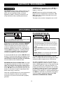
This tool is intended for use on a circuit that has an
electrical receptacle as shown in Figure 1-1. Figure 1-1
shows a NEMA approved 3-wire, 15 amp electrical plug
and receptacle that have a grounding conductor. If a
properly grounded electrical receptacle is not available,
an adapter as shown in Figure 1-2 can be used to temporarily connect this plug to a 2-contact ungrounded
receptacle. The adapter has a rigid lug extending from it
that MUST be connected to a permanent earth ground,
such as a properly grounded receptacle box. THIS
ADAPTER IS PROHIBITED IN CANADA.
IMPROPER ELECTRICAL CONNECTION of the equipment-grounding conductor can result in risk of electric
shock. The conductor with the green insulation (with or
without yellow stripes) is the equipment-grounding conductor. DO NOT connect the equipment-grounding conductor to a live terminal if repair or replacement of the
electric cord or plug is necessary.
Check with a qualified electrician or service personnel if
you do not completely understand the grounding
instructions, or if you are not sure the tool is properly
grounded.
15
EXTENSION CORDS
Fig. 1-1
!
WARNING
To reduce the risk of fire or electrical shock, use the
proper gauge of extension cord. When using an
extension cord, be sure to use one heavy enough to
carry the current your machine will draw.
The smaller the gauge-number, the larger the diameter
of the extension cord is. If in doubt of the proper size of
an extension cord, use a shorter and thicker cord. An
undersized cord will cause a drop in line voltage resulting in a loss of power and overheating.
Fig. 1-2
!
CAUTION
USE ONLY a 3-wire extension cord that has a 3-prong
grounding plug and a 3-pole receptacle that accepts the
machine’s plug.
If you are using an extension cord outdoors, be sure
it is marked with the suffix “W-A” (“W” in Canada) to
indicate that it is acceptable for outdoor use.
Make certain the extension cord is properly sized, and
in good electrical condition. Always replace a worn or
damaged extension cord immediately or have it
repaired by a qualified person before using it.
Protect your extension cords from sharp objects, excessive heat, and damp or wet areas.
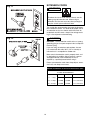
MINIMUM RECOMMENDED GAUGE FOR EXTENSION CORDS (AWG)
115 VOLT OPERATION ONLY
16
25’ LONG
50’ LONG
100’ LONG
0 to 6 Amps
18 AWG
16 AWG
16 AWG
6 to 10 Amps
18 AWG
16 AWG
Not recommended
10 to 12 Amps
16 AWG
16 AWG
Not recommended
Check shipping carton and machine for damage before
unpackaging. Carefully remove packaging materials,
parts and machine from shipping carton. Always check
for and remove protective shipping materials around
motors and moving parts. Lay out all parts on a clean
work surface.
Compare the items to inventory figures; verify that all
items are accounted for before discarding the shipping
box.
Remove any protective materials and coatings from all of
the parts and the mini lathe. The protective coatings can
be removed by spraying WD-40 on them and wiping it
off with a soft cloth. This may need to be redone several
times before all of the protective coatings are removed
completely.
If any parts are missing, do not attempt to plug in the
power cord and turn “ON” the machine. The machine
should only be turned “ON” after all the parts have been
obtained and installed correctly. For missing parts,
contact Steel City at 1-877-SC4-TOOL.
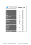
Model 60170G
A
B
E
G
D
F
C
H
A)
Lathe
E)
Lock handles
B)
Switch
F)
Tailstock spindle with ball bearing live center
C)
Special wrench
G)
Drive center spindle
D)
Tool rest
H)
Knock-out rod
17
Model 60100G
B
A
F
G
C
H
E
D
A)
Lathe
E)
Lock handles (2)
B)
Switch
F)
Tailstock spindle with ball bearing live center
C)
Special wrench
G)
Drive center spindle
D)
Tool rest
H)
Knock-out rod
18
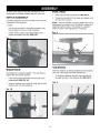
d
A
C
B
A
B
A
19
B
Fig. 4
C
D
B
A
A
E C
20
A
B
A
C
B
21
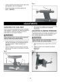
CHANGING SPINDLE SPEEDS
(MODEL60170G ONLY)
2.
THIS SECTION ONLY APPLIES TO THE 5 SPEED
MINI LATHE, MODEL 60170G. FOR INFORMATION
ON CHANGING SPEEDS ON THE VARIABLE
SPEED MINI LATHE, MODEL 60100G, REFER TO
THE CHANGING SPINDLE SPEEDS SECTION THAT
FOLLOWS THIS SECTION.
Loosen the motor plate lock handle (E) and lift upon
the motor plate lever (D) to take the tension off of
the belt. SEE FIGS. 12
Fig. 12
1.Lossen the screw (A) and open the left pulley cover
(B) to expose the pulleys. SEE FIGS.10 and 11.
D
Fig.10
A
E
Fig. 11
3.
Move the belt (F) to the desired pulley groove
according to the speed chart (G) on the inside of
the upper access door. Be sure that the belt is
aligned with the spindle pulley and the motor pulley.
SEE FIG. 11 and 12 and 13
4.
Tension the belt by pushing down on the motor
plate lever (D) and retightening the motor plate lock
handle (E).
Fig. 13
F
G
B
22
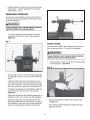
CHANGING SPINDLE SPEEDS
(MODEL60100G ONLY)
THIS SECTION ONLY APPLIES TO THE VARIABLE
SPEED MINI LATHE, MODEL 60100G. FOR
INFORMATION ON CHANGING SPEEDS ON THE5
SPEED MINI LATHE, MODEL 60170G, REFER TO
THE CHANGING SPINDLE SPEEDS SECTION THAT
PRECEDES THIS SECTION.
The variable speeds of the lathe are controlled by the
speed knob on the variable speed control switch, as well
as the position of the belt on the pulleys. The speed
ranges for the pulley are marked on the control switch.
Determine which speed range you wish to work in
before adjusting the spindle speed.
2.
Loosen the motor plate lock handle (E) and lift upon
the motor plate lever (D) to take tension off of the
Belt. SEE FIG. 12, page 22.
3.
Refer to the chart on the variable speed
Control switch and move the belt (F) to the desired
Pulley groove. Make certain that the belt is aligned
With the motor pulley and the spindle pulley.
SEE Fig. 15
4.
Tension the belt by pushing down on the motor
plate lever and lock in place with the motor plate
lock handle.
VARIABLE SPEED CONTROL
(MODEL60100G ONLY)
THIS SECTION APPLIES ONLY TO THE VARIABLE
SPEED MINI LATHE, MODEL NUMBER 60100G. IF
THIS IS NOT YOUR MODEL, YOU MAY SKIP THIS
SECTION.
1.Lossen the screw (A) and open the left pulley cover
(B) to expose the pulleys. SEE FIGS.14 and 15.
Fig.14
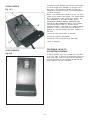
The variable speed control switch contains the electrical
connections to the motor and has three external controls. They are as follows
1.ON/OFF Switch.
A
2.Speed Control Knob
3.Thermal Reset Button
The ON/OFF (A) switch controls electrical power to the
lathe motor. The lathe will begin turning when the ON
button is pressed. It will take up to 3 seconds before the
lathe comes up to full speed. The time at which the
lathe comes up to full speed is determined by the size
and weight of the workpiece. To turn the motor off, push
the OFF button and wait for the unit to come to a complete stop. SEE FIG. 16, page 24.
Fig.15
B
F
23
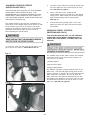
60100G SWITCH
The Speed Control Knob(B) sets the speed of the lathe
to suit the weight of the workpiece or the type of tool
being used. After the lathe is started, turn the knob
clockwise to increase the speed , turn counterclockwise
to reduce the speed.
Fig. 16-1
A
NOTE: The variable speed knob is not the only determinate of the speed of the spindle. The spindle speed
also is determined by the setting of the pulleys. For
more information on the pulley settings, refer to
CHANGING SPINDLE SPEEDS (MODEL60100G
ONLY)in the ADJUSTMENTS section of this manual.
The Thermal Reset Button (C) provides 8-amp
overload protection. If the lathe stops suddenly during
operation or does not start when the ON button is
pushed, an overload condition may have occurred. In
this case:
B
1.Press the OFF button.( Also for 60170G)
2.Press the Thermal Reset Button.
3.Restart the lathe by pressing the ON button.
( Also for 60170G)
C
FASTENING LATHE TO
SUPPORTING SURFACE
60170G SWITCH
Fig.16-2
If during operation there is any tendency for the lathe
to tip over, slide, or walk on the supporting surface, the
base of the lathe must be secured to the supporting
surface with fasteners (not supplied) through the four
holes located in the feet of the lathe.
24
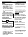
OPERATIONS
TRIAL RUN
4. Position the tool rest so that it sits 1/8” away from
the edge of the workpiece. Rotate the workpiece
by hand to make sure that it does not come in
contact with the tool rest
Once all of the lathe has been assembled and all of the
adjustments have been made, its time for a trial run.
1. Turn variable Speed knob to it’s lowest setting.
(This applies to Model 60100G only. Model 60170G
Owners can skip this step.)
5. Turn the lathe ON. When first starting out, make
sure that lathe is set to run at its slowest speed. As
you become more comfortable and gain experience
with the lathe, you may increase the speed of the
spindle.
2. Press the ON button. Keep your hand near the
switch, ready to shut the machine down in case
anything does not sound right or if there appears to
be a problem.
6. When cutting, the object is to cut the outer layer of
the workpiece to a designed depth then hold the
cutting tool steady with the beveled edge parallel to
the outer edge of the workpiece. The way to hold
the cutting tool steady is to rest it on the tool rest.
NEVER perform freehand operations without the
tool rest as serious injury can occur.
3. The lathe should run smoothly with little to no
vibration. If any strange noises or loose parts are
noticed, shut the machine down and recheck all
adjustments.
4. If everything seems to be in order, you are now
ready to turn some wood.
!
NOTICE: The following section is designed to
give instructions on the basic operations of this
lathe. It is in no way comprehensive of every
lathe operation. It is STRONGLY recommended
that you read books, trade magazines, or get
formal training to maximize the potential of your
lathe and to minimize the risks.
Proper tool rest placement is ESSENTIAL to good
results and CRITICAL for safety. A tool rest that is
positioned too low will result in too much bite which will
make the cutting tool very difficult to handle. A tool rest
that is positioned too high can result in a dangerous
kickback. If the tool rest is too far away from the workpiece, it will be difficult to hold the cutting tool because
of reduced leverage. Remember as a general rule to
ALWAYS keep the tool rest positioned 1/8” away from
the outermost edge of the workpiece.
TURNING BETWEEN CENTERS
!
WARNING
WARNING
FACEPLATE TURNING
Faceplate turning is primarily used in the turning of
bowls or bowl shaped items.
ALWAYS wear eye protection. Any machine can
throw debris into the eyes during operations, which
could cause severe and permanent eye damage.
Everyday eyeglasses are NOT safety glasses.
ALWAYS wear Safety Goggles (that comply with
ANSI standard Z87.1) when operating power tools.
1. Remove as much excess material from the inside
and outside of the workpiece before attaching to
the lathe
2. The workpiece should be fastened to the faceplate
using wood screws(not included). Make certain
that the screws drive in about halfway through the
bottom of the workpiece.
It is always a good idea to start with a small workpiece
to get used to the feel of the lathe. Once you select
your workpiece:
3. Position the tool rest so that you can shape the
outside of the workpiece first.
1. Using a straight edge, draw an X from corner to
corner, where the center of your X is the center of
the workpiece.
4. Once outside work has been completed, disconnect
the machine from the power source and reposition
the tool rest so that is opposite the face of the
workpiece.
2. Place your workpiece between the Headstock Drive
Center Spindle and the Tailstock Spindle, making
sure that the centers that you marked in Step 1 go
into the centers of their respective spindles.
5. Reconnect power supply, turn the machine on, and
proceed to hollow out the workpiece.
3. Lock down the tailstock assembly using the lever,
then crank the handwheel clockwise until the workpiece is held firmly in place.
25
Fig.17
A
Fig. 18
B
1.
26
Loosen the screw (A) at the top of pulley cover and
open the left pulley cover (B).
SEE FIG. 17 and 18.
2.
Loosen the HD screw (C) and open the right pulley
cover and expose the pulleys. SEE FIG. 19
3.
Loosen the motor plate lock handle (D) and lift
upon the motor plate handle (E) to take tension off
of the belt. SEE FIG 20.
4.
Place the new belt on the spindle pulley. Make
certain that the belt is aligned With the motor pulley
and the spindle pulley.
5.
Tension the belt using the motor plate handle
and lock in place with the motor plate lock handle.
6.
Thread the right pulley cover and left pulley cover
and tighten the screws.
Fig. 20
D
Fig. 19
E
C
27
TROUBLESHOOTING GUIDE
TO PREVENT INJURY TO YOURSELF or damage to the lathe, turn the switch to the OFF position and unplug the
power cord from the electrical receptacle before making any adjustments.
PROBLEM
LIKELY CAUSE(S)
SOLUTION
Excessive vibration.
1. Workpiece warped, out of round, has major
flaw, improperly prepared for turning, or RPM
is set too high.
1. Correct problem by planing, bandsawing, reduce the RPM,
or scrap workpiece all together.
Motor or spindle
stalls or will not
start.
Motor fails to
develop full power.
2. Worn spindle bearings.
2. Replace bearings.
3. Worn belt.
3. Replace belt.
4. Motor mount bolts loose.
4. Tighten bolts.
5. Lathe on uneven surface.
5. Move to a different surface or bolt to a workbench or stand.
1. Excessive cut.
1. Reduce cut depth.
2. Defective motor.
2. Replace motor.
3. Broken belt.
3. Replace belt.
4. Worn spindle bearings.
4. Replace bearings.
5. Capacitor is bad (Model 60170G only)
5. Replace the capacitor (Model 60170G only).
6. Brushes are bad (Model 60100G only)
6. Replace brushes (Model 60100G only).
1. Power line overloaded.
1. Correct overload condition.
2. Undersize wires in supply system, or
extension cord is too long.
2. Increase supply wire size.
3. Low voltage.
3. Request voltage check from power company and correct
low voltage condition.
4. Capacitor is bad (Model 60170G only).
Tools tend to grab
or dig in.
Tailstock moves
when applying
pressure.
4. Replace capacitor (Model 60170G only).
5. Defective motor.
5. Replace motor.
1. Dull tools.
1. Sharpen tools.
2. Tool support set too low.
2. Reposition tool support height.
3. Tool support set too far from workpiece.
3. Reposition tool support closer to workpiece.
4. Improper tool being used.
4. Use correct tool for operation.
1. Tailstock clamping device not adjusted
properly.
1. Tighten nut beneath the tailstock.
2. Lathe bed and tailstock mating surfaces are
greasy or oily.
2. Remove and clean surfaces with a cleaner degreaser.
28
u NOTES u
29
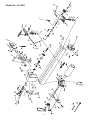
Model No: 60170G
30
Model No.: 60100G
31
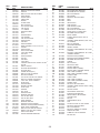
KEY
NO.
PART
NO.
1
2
3
4
5
6
7
8
9
10
11
12
13
14
15
16
17
18
19
20
21
22
23
24
25
26
27
28
29
30
NA
OR94201
OR71639
OR90222
OR71638
OR71667
OR71668
OR71669
OR71670
OR90927
OR94200
OR71671
OR94199
OR71635
OR71633
OR71610
OR71632
OR71634
OR71624
OR71636
OR71637
SC10549
OR71672
OR71624
OR94197
OR71673
OR71674
OR71629
OR71630
OR71675
OR71676
OR71696
31
32
33
34
35
36
37
38
39
40
41
42
43
44
45
46
47
48
49
50
51
52A
52B
53
54
54A
55
56
OR71677
OR71678
OR71655
OR94203
OR90306
OR90502
OR71697
OR90761
OR90362
OR90381
OR71610
OR71609
OR71608
OR71607
OR94196
OR71679
OR94195
OR94194
OR94193
OR94192
OR94191
OR71659
OR71698
OR71603
SC80435
OR90239
OR94227
OR71680
DESCRIPTION
QTY.
M6x55mm SHOULDER SCREW
1
HANDLE
1
M6x10mm HEX SOC SET SCREW
1
HAND WHEEL
1
SCREW SHAFT
1
LIMIT PLATE
1
SPRING
2
CLAMP PLATE
2
M10 LOCK NUT
2
1
Φ10 EXT RET RING
TAIL STOCK
1
1
Φ12 E-RING
SPINDLE SCREW
1
QUILL
1
CENTER POINT
1
LIVE CENTER
1
TAIL STOCK SCALE
1
HANDLE ASSY
1
CAM ROD
1
HANDLE SLEEVE
1
WAVE WASHERΦ15.2xΦ21.2xΦ0.4
1
STATOR
1
HANDLE ASSY
2
Φ12 ΕΧΤ RET RING
2
1
ΤΟΟL REST BASE
EYE BOLT
1
HANDLE SLEEVE
1
COLLAR
1
CAM ROD
1
TOOL REST
1
5-SPEED SWITCH ASSY CONST OF REF
31#-40#
1
SWITCH J4062W
1
ELECTRIC-BOX-BRACKET
1
ELECTRIC-BOX
1
STRAIN RELIFE (6P-4)
2
M6x12mm PAN HD SCREW
2
M6 LOCK WASHER
4
ST1.5x13mm PAN HD TAP SCREW
2
M5x10mm CHEESE HD SCREW
6
5.3mm EXT TOOTH WASHER
2
M5 HEX NUT
2
CENTER POINT
1
DRIVING CENTER
1
FACE PLATE
1
WASHER
1
KEY A5x36
1
SPINDLE SHAFT
1
BEARING 6005-2RS
1
1
Φ47 INT RET RING
1
Φ42 INT RET RING
WAVE WASHER
1
BEARING 6004-2RS
1
SPINDLE PULLEY(5-SPEED)
1
SPINDLE PULLEY(VARIABLE SPEED)
1
HEAD STOCK HANDWHEEL
1
M6x12mm HEX SOC SET SCREW
4
M6x6mm HEX SOC SET SCREW
2
2
Φ20 EXT RET RING
FRONT MOUNTING BRACKET
1
32
KEY
NO.
PART
NO.
57
58
59
60
61
62
63
64
65
66
67
68
69
70
71
72A
OR71681
OR71682
OR90248
OR90311
OR93381
OR71683
OR71684
OR71685
OR74265
OR71611
OR90502
OR71686
OR71687
OR71699
OR71688
OR71689
72B
OR74293
73
74
75
76A
OR94197
OR71690
OR71642
OR71691
M8 FLAT WASHER
1
ADJUSTING BRACKET
1
HANDLE SLEEVE
1
76B
OR74294
MULTIPLE CUNIFORM BELT 4PJ L=889
(VARIABLE SPEED)
1
77A
77B
78
79
80
81
82
83A
83B
84A
84B
85
86
87A
87B
88
104
N/A
OR71660
OR71693
OR71692
OR74295
OR92724
OR71615
OR71614
OR70377
OR74296
OR71694
OR74297
OR71619
OR71620
OR91695
OR74298
OR71616
OR90306
OR74299
MOTOR PULLEY(5-SPEED)
89
90
91
92
93
94
95
96
97
98
99
100
101
102
103
OR71677
OR74300
OR74301
OR71650
OR71644
OR90381
OR94203
OR71649
OR94205
OR90306
OR90502
OR90761
OR71645
OR90362
OR90381
SWITCH J4062W
DESCRIPTION
QTY.
BACK MOUNTING BRACKET
1
M8x120MM HEX HD SCREW
4
M8 LOCK WASHER
9
M8 WASHER
8
M8x20mm HEX HD SCREW
4
BED I
1
BED II
1
HEAD STOCK
1
WIRE JACKET
2
WIRE SPRING CLAMP
1
M6 LOCK WASHER
1
BACK PULLEY COVER ASSY
1
FRONT PULLEY COVER ASSY
1
M5x12MM PAN HD SCREW
2
M4X40 SCREW
1
5-SPEED MOTOR(1/2HP 120V AC
1725RPM)
1
VARIABLE SPEED MOTOR (1/2HP 120V
3A 3700RPM)
1
MULTIPLE CUNIFORM BELT 3PJ L=863
(5-SPEED)
1
1
MOTOR PULLEY(VARIABLE SPEED)
1
M6x40MM HEX HD SCREW
2
SLEEVE
2
M8 LOCK NUT
1
KNOCK OUT BAR
1
SPINDLE WRENCH
1
MOTOR LABEL (5-SPEED)
1
MOTOR LABEL (VARIABLE SPEED)
1
SPEC LABEL (5-SPEED)
1
SPEC LABEL (VARIABLE SPEED)
1
WARING LABEL
1
CLIENT LABEL
1
SPEC LABEL (5-SPEED)
1
SPEC LABEL (VARIABLE SPEED)
1
POWER CORD
1
1
M6x12mm PAN HD SCREW
VARIABLE SPEED SWITCH ASSY CONST
OF 89#--103#
1
1
ADJUSTABLE CAPACITOR
1
ELECTRIC-BOX-BRACKET
1
RESET SWITCH ZE-800 8AMP
ELECTRIC-BOX
M5 NUT
STRAIN RELIFE (6P-4)
PCB
ST2.9x16mm PAN HD TAP SCREW
M6x12mm PAN HD SCREW
M6 LOCK WASHER
M5x10mm CHEESE HD SCREW
DIRECTION CHART
5.3MM EXT TOOTH WASHER
M5 HEX NUT
1
1
4
2
1
4
2
4
6
1
2
2
u NOTES u
33
STEEL CITY
TOOL WORKS
www.steelcitytoolworks.com
1-877-SC4-TOOL
(1-877-724-8665)
u
5 Year Warranty
34