1
FJM RD040MHXCA_IM_00000_E_2.23.10.indd 1
2010-2-24 19:56:20
Contents
SAFETY PRECAUTIONS . . . . . . . . . . . . . . . . . . . . . . . . . . . . . . . . . . . . . . . . . . . . . . 3
PREPARING THE INSTALLATION
Locating the Units . . . . . . . . . . . . . . . . . . . . . . . . . . . . . . . . . . . . . . . . . . . . . . 6
INSTALLING THE UNIT
Installing the Refrigerant Pipe Work . . . . . . . . . . . . . . . . . . . . . . . . . . . 14
Electrical Connections . . . . . . . . . . . . . . . . . . . . . . . . . . . . . . . . . . . . . . . . . 25
COMPLETING THE INSTALLATION
Setting the Option Switch and Function of the Keys . . . . . . . . . .
Pump Down Procedure . . . . . . . . . . . . . . . . . . . . . . . . . . . . . . . . . . . . . . .
Completing the Installation . . . . . . . . . . . . . . . . . . . . . . . . . . . . . . . . . . .
Final Checks and Trial Operation . . . . . . . . . . . . . . . . . . . . . . . . . . . . . . .
Pump Down Procedure (When removing the product) . . . . . . . .
Troubleshooting . . . . . . . . . . . . . . . . . . . . . . . . . . . . . . . . . . . . . . . . . . . . . . .
31
33
36
36
37
38
E-2
FJM RD040MHXCA_IM_00000_E_2.23.10.indd 2
2010-2-24 19:56:20
ENGLISH
Safety Precautions
You must install the product by qualified installer. If you install the product on your own or by unqualified
person, Samsung is not responsible for any damages which may occur due to incorrect installation.
Make sure to read the following safety precautions carefully before installation.
Make sure to observe the cautions specified in this manual.
Conduct a test run of the unit after installation and then explain all system functions to the owner.
Follow IEC (International Electrotechnical Commission) standards for the power input and
ISO (International Standards Organization) standards for input current.
R410a refrigerant is used for Super FJM air conditioner.
- When using R410a, moisture or foreign substances may affect to the capacity and reliability of
the product. Safety precautions must be taken when installing the refrigerant pipe.
- The design pressure of the unit is 4.1MPa(594.6psi). Select appropriate material and thickness
according to the regulations.
- R410a is a quasi-azeotrope of two refrigerants.
Make sure to charge liquid one when adding refrigerant.
If you charge gaseous refrigerant, it may affect the capacity and reliability of the product as
a result of change formation of the refrigerant.
Connect only the indoor units fit on R410a refrigerant. Check whether the indoor units can be
connected with the product’s catalogue.
(When incorrect indoor units are connected, they cannot operate normally.)
When installing, use tools and materials for R410a only. If you use tools and materials for R22,
there is potential risk of bursting, injury, electric shock and fire because the pressure of R410a is
higher than the pressure of R22(conventional).
E-3
FJM RD040MHXCA_IM_00000_E_2.23.10.indd 3
2010-2-24 19:56:20
Safety Precautions (Continued)
WARNING Hazards or unsafe practices that may result in severe personal injury or death.
CAUTION Hazards or unsafe practices that may result in minor personal injury or property damage.
WARNING
Hazards or unsafe practices that may result in severe personal injury or
death.
Installation must be carried out by a qualified installer. Do not attempt to repair, move, modify or reinstall
the unit on your own since such act may cause fire, electric shock or water leakage.
Install the unit in a place where it is strong enough to hold the product weight. When installed in place
where it is not strong enough to withhold the product weight, the unit could fall and cause injury.
The unit should be installed in accordance with the National Electrical regulations. Check if the voltage
and the frequency of the main power supply are those required for the unit to be installed and check
the connection. Do not share the power outlet with other appliances. Incomplete connection, defective
insulation or exceeding the permissible current may cause electric shock or fire.
Use the specified wires to connect the indoor and outdoor units securely and attach the wires firmly to
the terminal block connecting sections so that the pressure is not applied to the sections. Inappropriate
connection and fixing could cause fire.
Attach the electrical cover to the indoor and outdoor unit securely without any gaps. If there are any
gaps, there is potential risk of fire or electric shock due to dust or water.
Make sure to use the part provided or specified parts for the installation work. The use of defective parts
could cause an injury or leakage of water due to a fire, an electric shock, the unit falling, etc.
Make sure that the refrigerant gas does not leak after completing the installation. If the refrigerant gas of
the indoor unit leaks and comes into contact with the fan heater, space heater or stove, harmful gas will
be generated.
Ensure that the national safety code requirements have been followed for the main supply circuit. Ensure
that a proper ground wire is in place. Do not connect the ground to a gas pipe, water pipe, lightning rod
or telephone grounding. Defective grounding could cause electric shock.
Do not install the unit in a place with direct sunlight, dangerous substances or where it is exposed to
inflammable gas leakage to prevent explosion, fire or personal injury.
Perform the installation securely referring to the installation manual. Incomplete installation could cause
personal injury due to fire, electric shock and water leakage or from the unit falling.
Check first the following situations before starting the operation during the installation.
- The pipe must be properly connected and make sure there is no leakage.
- Service valves must be open. If compressor is operated with the service valve closed, excessive pressure
may damage parts of the compressor.
If leakage occurs on any of the connection, air inflow may also cause excessive pressure that could lead
to explosion.
Stop the compressor before disconnecting the refrigerant pipe for pump-down operation. If you
disconnect the refrigerant pipe while compressor is operating with service valve open, air inflow will
cause excessive pressure in the refrigerant cycle that could lead to explosion and personal injury.
Do not assemble the power cord on your own, use two cables together to extend the cable length or
tangle the cable. Bad connection, isolation and over voltage may cause fire or electric shock.
Make sure to turn off the main power when setting up the indoor unit electrical circuit or power cords.
There is a risk of electric shock.
Make sure that proper circuit breaker and safety switches are installed. Install a ground leakage breaker
depending on the installation place (where it is humid). If not, it may cause electric shock.
Do not install the unit by yourself (owners). Incorrect installation of the unit could cause injury due to
fire, electric shock and water leakage or from the unit falling. Consult a dealer or a qualified installer.
Use the unit on a single outlet circuit. Do not share the power outlet with other appliances. Obtain the
consent by a qualified installer before connecting the unit to the power supply system. An all pole
disconnection from the power supply must be incorporated in the fixed wiring with a contact opening
of >3mm(1/8in).
Manufacturer is not responsible for accidents due to incorrect installation.
When you install the air conditioner in a small room, you consider a proper ventilation to prevent a
leakage level within the maximum permissible limit.
- In that case, you may die from suffocation by some possibility.
Fix the outdoor unit securely to prepare against strong wind or earthquake.
- If the outdoor unit is not properly fixed, it turns over and accidents may occur.
E-4
FJM RD040MHXCA_IM_00000_E_2.23.10.indd 4
2010-2-24 19:56:21
ENGLISH
If any gas or impurities except R410a refrigerant come into the refrigerant pipe, serious problem may
occur and it may cause injury.
Install the cables with supplied cables firmly. Fix them securely so that external force is not exerted to
the terminal board.
- If the connection or fixing is incomplete, it can cause trouble with a heat generation, electric shock or
fire and so on.
CAUTION
Hazards or unsafe practices that may result in minor personal injury or
property damage.
Perform the drainage/piping work securely according to the installation manual. If not, water could
drop from the unit and household goods could get wet and damaged.
Fasten a flare nut with a torque wrench as specified in this installation manual. When fastened too
tight, a flare nut may break after a long period of time and cause refrigerant leakage.
Wear thick gloves during the installation process. If not, personal injury may occur due to the air
conditioner parts.
Be careful not to touch the outdoor unit inlet or aluminum pins. You may get personal injury.
Do not install the outdoor unit in a place where animals could live. If an animal get contact with the
electric parts, damage or fire may occur. In addition ask the customer to maintain a clean installation
place around it.
After completing the installation run the trial operation. If no error occurs, explain to the customer
how to use and clean the air conditioner according to the user’s manual. In addition give the
installation manual and the user’s manual to the customer.
Check the unit for damage that may have taken place during transportation and do not install or use
damaged equipment.
All of the manufacturing and packaging material used for your new appliance are compatible with
the environment and can be recycled.
Dispose of the packaging material in accordance with the local requirements.
This product is an air conditioning system and contains a coolant that must be recovered and
disposed of in an appropriate way by qualified personnel. At the end of the life cycle, take it to a
proper recycling or disposal center or return it to the dealer so that it can be disposed correctly.
Do not connect the heater to the outdoor unit and do not install remodeled duct as you please.
- The capacity of the air conditioner may reduce, electric shock or fire may occur and it has a chance of
occurrence of and accident like electric shock or fire.
Make sure that the condensed water dripping from the drain hose runs out properly and insulate the
drain pipe so that frost does not generate.
- Household goods may get wet if the drain pipe is not properly installed.
Install the power cable and communication cable of the indoor and outdoor unit at least 1.5m(5ft)
away from electric appliances.
- Noise may hear depending on the electric wave though the cables are installed away from electric
appliances.
Install the indoor unit away from lighting apparatus using the ballast.
- If you use the wireless remote control, it may not operate normally.
The air conditioner should be used only for the applications for which it has been designed: the
indoor unit is not suitable to be installed in areas used for laundry.
Our units must be installed in compliance with the spaces indicated in the installation manual to
ensure either accessibility from both sides or ability to perform routine maintenance and repairs. The
units’ components must be accessible and that can be disassembled in conditions of complete safety
either for people or things.
For this reason, where it is not observed as indicated into the Installation Manual, the cost necessary
to reach and repair the unit (in safety, as required by current regulations in force) with slings, trucks,
scaffolding or any other means of elevation won’t be considered in-warranty and charged to end user.
E-5
FJM RD040MHXCA_IM_00000_E_2.23.10.indd 5
2010-2-24 19:56:22
PREPARING THE INSTALLATION
Locating the Units
Deciding on Where to Install the Outdoor Unit
Decide the installation location regarding the following condition and obtain the user’s approval.
The outdoor unit must not be placed on its side or upside down, as the compressor lubrication oil will run
into the cooling circuit and seriously damage the unit.
Choose a location that is dry and sunny, but not exposed to direct sunlight
or strong winds.
Do not block any passageways or thoroughfares.
Choose a location where the noise of the air conditioner when running and the discharged air do not
disturb any neighbours.
Choose a position that enables the pipes and cables to be easily connected to the indoor unit.
Install the outdoor unit on a flat, stable surface that can support its weight and does not generate any
unnecessary noise and vibration.
Position the outdoor unit so that the air flow is directed towards the open area.
Place the outdoor unit where there are no plants and animals because they may cause malfunction of
outdoor unit.
Maintain sufficient clearance around the outdoor unit, especially from a radio, computer, stereo system,
etc.
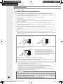
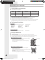
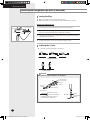
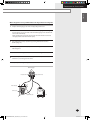
When installing the outdoor unit near seashore, make sure it is not directly exposed to sea breeze.
If you can not find a adequate place without direct see breeze, make sure to apply anti-corrosion coating
on the heat exchanger.
- Install the outdoor unit in a place (such as near buildings etc.) where it can be prevented from sea
breeze which can damage the outdoor unit.
Sea
breeze
Outdoor
unit
Sea
breeze
Sea
Outdoor
unit
Sea
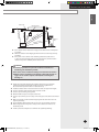
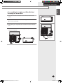
- If you cannot avoid installing the outdoor unit by the seashore, construct a protection wall around to
block the sea breeze.
Protection wall
Sea
breeze
Sea
Outdoor
unit
Protection wall should be constructed with a solid
material such as concrete to block the sea breeze and
the height and the width of the wall should be 1.5 times
larger than the size of the outdoor unit. Also, secure
over 700mm(2.3ft) between the protection wall and the
outdoor unit for exhausted air to ventilate.
- Install the outdoor unit in a place where water can drain smoothly.
If you cannot find a place satisfying above conditions, please contact manufacturer. Make sure to clean
the sea water and the dust on the outdoor unit heat exchanger.
Do not install the air conditioner in following places.
- The place where there is mineral oil or arsenic acid.
There is a chance that parts may get damaged due to burned resin.
The capacity of the heat exchanger may reduce or the air conditioner may be out of order.
- The place where corrosive gas such as sulfurous acid gas generates from the vent pipe or air outlet
The copper pipe or connection pipe may corrode and refrigerant may leak.
- The place where there is a danger of existing combustible gas, carbon fiber or flammable dust.
The place where thinner or gasoline is handled.
CAUTION
E-6
Do not install the outdoor unit in a snowy and cold area (low temperature and high humidity area
- where the temperature is below -7°C(19.4°F) and humidity is higher than 85%) because according
to operation condition (defrost, etc.), ice may be formed in the drain route. If the ice is accumulated,
it may cause critical damage to the product.
ex) lakeside of cold area in winter time, seashore, alpine region and etc.
RD040MHXCA_IM_32073_E_4.06.10.indd 6
2010-4-19 15:51:36
ENGLISH
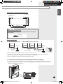
PREPARING THE INSTALLATION
Indoor Unit
Remote Control
1m(3.28ft)
1m or more
(
or m3.28ft
ore )
Breaker
) or more
1.5m(5ft
Breaker
Stereo
ore
r m re
)o
t
f
mo
5
m( ft) or
1.5
5
(
m
1.5
e
r mor
0ft) o
3m(1
Outdoor
Unit
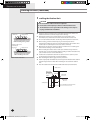
If the outdoor unit is installed at a height, ensure that its base is firmly fixed
in position.
Make sure that the water dripping from the drain hose runs away correctly
and safely.
If the paint on the cabinet comes off during installation, make sure to
re-paint or protect damaged area to prevent rust. If the cabinet becomes
rusted, it may reduce durability of the outdoor unit.
CAUTION
You have just purchased a system air conditioner and it has been
installed by your installation specialist.
This device must be installed according to the national electrical rules.
With an outdoor unit having net weight upper than 60kg(132.3lb), we
suggest do not install it suspended on wall, but considering floor
standing one.
Avoid a place that may disturb your neighbor. Noise may occur from the
outdoor unit and the discharged air may run into the neighborhood.
(Be careful of the operation time in a residential area.)
Install the outdoor unit on a hard and even area that can support its weight.
Choose a flat place that rainwater does not settle or leak.
Choose a place avoiding strong winds.
Maintain sufficient space for repairs and service.
Choose a place where you can easily connect the pipes and cables to the indoor
unit.
Make sure that the condensed water dripping from the drain hose runs out
properly and safely.
If you install the outdoor unit by the sea or a spa, concern about corrosion.
Build a support where may have a heavy snow so that the air intake is not
blocked by snow.
Install a protective safety fence to eliminate the possibility of falling.
E-7
FJM RD040MHXCA_IM_32073_E_3.17.10.indd 7
2010-3-17 18:53:10
PREPARING THE INSTALLATION
Locating the Units (Continued)
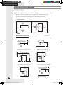
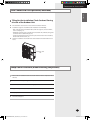
Space Requirements for Outdoor Unit
Observe the clearances and dimensions as seen below when installing the outdoor unit.
If you install several outdoor units simultaneously, observe the space for ventilation and free airflow.
If the space for ventilation is insufficient, the air conditioner may be inefficient.
SAMSUNG logo is attached on the front side of the outdoor unit.
Figure Description
Top view
Side view
Back side: Air intake
Front side:
Air outlet
Back side:
Air intake
Front side: Air outlet
,
Air flow direction.
When installing 1 outdoor unit
When the air outlet is toward the wall
300(12) or more
are blocked by the wall
The upper part of the outdoor unit
and the air outlet is toward the wall
2000(80) or more
150(6) or more
600(24) or more
The upper part of the outdoor unit and
the air outlet is opposite the wall
300(12)
or more
When the walls are blocking front and
the rear side of the outdoor unit
1500(60)
or more
500(20) or more
1500(60) or more
When 3 sides of the outdoor unit
1500(60) or more
300(12)
or more
When the air outlet is opposite the wall
Unit : mm(inch)
300(12)
or more
E-8
FJM RD040MHXCA_IM_00000_E_2.23.10.indd 8
2010-2-24 19:56:25
ENGLISH
PREPARING THE INSTALLATION
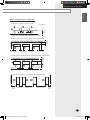
When installing more than 1 outdoor unit
When the air outlet is toward the wall
1500(60)
or more
Unit : mm(inch)
600(24)
or more
600(24)
or more
300(12)
or more
When 3 sides of the outdoor unit are blocked by the wall
300(12) or more
600(24) or more
600(24) or more
600(24) or more
600(24) or more
600(24) or more
1500(60)
or more
300(12)
or more
When the walls are blocking front and the rear side of the outdoor units
When front and rear side of the outdoor unit is toward the wall
1500(60)
or more
600(24) or more
3000(120) or more
3000(120) or more
300(12)
or more
E-9
FJM RD040MHXCA_IM_00000_E_2.23.10.indd 9
2010-2-24 19:56:25
PREPARING THE INSTALLATION
Locating the Units (Continued)
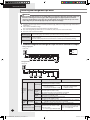
Selecting Outdoor Unit Combination
Install the indoor unit only for R410a.
Outdoor unit
(Series)
Capacity of the outdoor
unit (Btu/h)
Maximum of connected
indoor units
Total capacity of connected
indoor units (Btu/h)
RD040MHXCA
36,000
6
20,000~45,000
RD050MHXCA
48,000
8
27,000~60,000
Y
ou may connect indoor units within 50~130% of the outdoor unit capacity.
Smallest indoor unit(7,500Btu/h) was used to calculate ‘Maximum of connected indoor units’.
C
onnect maximum 6 to 8 indoor units to the selected outdoor unit.
T otal capacity of connected indoor units must be within the capacity of outdoor unit.
If all indoor units operate simultaneously when total capacity of indoor units exceeds 100% of the outdoor
unit, actual capacity of each indoor unit may be reduced a little as compared with its rated capacity.
Tools Required for Installation
General Tools
Vacuum Pump(Backward flowing prevention)
Stud Finder
Torque Wrench
Reamer
Pipe Bender
Screw Driver
Spanner
L Wrench
Measuring Tape
Manifold Gauge
Pipe Cutter
Spirit Level
Drill
Tools for test operations
Thermometer
Resistance Meter
Electroscope
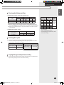
Moving the Outdoor Unit
Select the moving route.
Secure the strength of the carrying path to resist against the weight of the outdoor unit.
Do not slant the product more than 30˚ when carrying it. (Do not lay the product down sideways.)
The surface of the heat exchanger is sharp. Be careful not to be get injury while moving.
When moving with a crane or straps
In case of placing the outdoor unit on a high ground such as rooftop
- Fasten the wire rope as seen in the picture.
- Move the product with its package on, to prevent any damages
caused by the rope.
Wire rope/straps
Wood palette
When moving by installation personnel
When the moving distance of the product is close enough for
installation personnel to carry
- 2 people should move the product using the carry handle as shown in
the picture.
- Be careful not to damage the heat exchanger.
- Be careful not to get injured by the sharp edge of the heat exchanger.
E-10
FJM RD040MHXCA_IM_00000_E_2.23.10.indd 10
2010-2-24 19:56:27
ENGLISH
PREPARING THE INSTALLATION
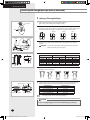
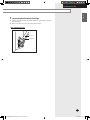
Disassembling the Leg Base and Wood Palette /
Fastening the Anchor Bolt
1
Disassemble the three screws (with an electric driver) which fixes wood
palette.
2
Disassemble the bottom-left screw with monkey spanner.
Do not remove guard fan.
3
After removing the wood palette, move the outdoor unit to the installation
place.
4
Fasten the bottom-left screw with monkey spanner first, and then fasten the
other three anchor bolts.
Wood palette
Monkey spanner
Screw
E-11
FJM RD040MHXCA_IM_00000_E_2.23.10.indd 11
2010-2-24 19:56:33
PREPARING THE INSTALLATION
Locating the Units (Continued)
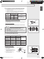
Installing the Outdoor Unit
CAUTION
Do not install the outdoor unit on a wood palette.
Fix the outdoor unit completely to the base surface with anchor bolts.
The manufacturer is not responsible for the damage occurred by not
keeping standard of the installation.
Drain hole
Unit : mm(inch)
150(6) or more
Install the outdoor unit higher than 150mm(6in) from the base surface and
install the drain hole to connect the pipe to the drainage.
If forward fan outdoor unit is installed where has average fallen snow
150mm(6in) over, outward duct should be attached to the outdoor unit.
< When installing on the ground >
Install the outdoor unit
horizontally on
the ground
The concrete foundation should be 1.5 times larger than bottom of the outdoor unit.
When heating, condensed water may be generated. Pay attention to
waterproof and drainage of the concrete foundation where the outdoor unit is
installed. (An ice road may form on the base surface in winter.)
Make up for wire mash or steel bar so that the outdoor unit is not damaged or
broken when installing concrete foundation.
When installing the outdoor units in same place simultaneously, install the
H beam inside concrete foundation. (When installing a number of outdoor unit,
you can install it on the concrete foundation.)
Install the H beam(150mm x 150mm x t10 (6inch x 6inch x t 3/8 inch) : basic
specification) to jut out from the concrete foundation.
After installing the H beam, apply corrosion protection.
Install a square pad(t=20mm(3/4 inch) or more) to prevent vibration of the outdoor
unit delivering to the base surface when installing the concrete for the outdoor
unit.
Place the outdoor unit on the H beam and fix it with the bolt, nut and washer.
150(6) or more
< When installing on the roof >
Base mount construction
Outdoor unit
Anchor bolt
Nut, Spring
washer
20mm
(3/4 inch)
A
Square pad
H beam
75mm(3inch)
A+10~20mm(3/8~3/4 inch) or more
E-12
FJM RD040MHXCA_IM_00000_E_2.23.10.indd 12
2010-2-24 19:57:21
ENGLISH
PREPARING THE INSTALLATION
Outdoor unit base mount and anchor bolt position
403(15-7/8)
375(14-3/4)
427(16-13/16)
Unit : mm(inch)
Anchor bolt position
(ø7, 4 holes )
670(26-3/8)
932(36-11/16)
CAUTION
When tightening the anchor bolt
Tighten the rubber washer to prevent the outdoor unit bolt connection part
from corroding.
Iron washer
Rubber washer
Installing the drain pipe
When installing 1 outdoor unit
When installing more than 1 outdoor unit
Outdoor unit
(Rear side)
Outdoor unit
(Rear side)
Outdoor unit
(Rear side)
Outdoor unit
(Rear side)
Open to air
Drain
plug
More than
1/50 slope
Open to air
Insulation
Drain
plug
More than 1/50 slope
Drain pipe covered with
insulation
Drain pipe
Open the upside of connected parts of outdoor units to prevent inner pressure.
Do not place a trap on the concentrated pipe. And install the drain pipe horizontally with a slope of 1/50 or more.
Insulate the drain pipe and drain plug by using the insulation over 10mm(3/8inch).
Install a self-regulation heat cable to prevent the drain pipe from freezing.
Caution When Installing Cover for Heating Air Direction Change
Parts shown in the picture is where the copper pipe may be passing by or the external plate may be near the copper
pipe. When using screw for installing the air direction changing device such as heating air cover, check and make sure
that it does not damage the copper pipe.
E-13
< Internal view from bottom>
FJM RD040MHXCA_IM_00000_E_2.23.10.indd 13
2010-2-24 19:57:22
INSTALLING THE UNIT
Installing the Refrigerant Pipe Work
WARNING
When installing, make sure there is no leakage. When recovering the refrigerant, ground the compressor
first before removing the connection pipe. If the refrigerant pipe is not properly connected and the
compressor works with the service valve open, the pipe inhales the air and it makes the pressure inside
of the refrigerant cycle abnormally high. It may cause explosion and injury.
Install the refrigerant pipe within the maximum allowable length, difference in height and length of after the first
branch pipe.
The pressure of the R410a is high.
Use only rated refrigerant pipe and follow the installation method.
Use clean refrigerant pipe which there is no harmful ion, oxide, dust, iron content or moisture.
Use tools and accessories fit on R410a.
Manifold gauge
Use manifold gauge only for R410a to prevent the inflow of foreign substances.
Vacuum pump
Use vacuum pump with check valve to prevent pump oil from flowing backward while the vacuum
pump is stopped.
Use the vacuum pump that the vacuum induction is available up to 5Torr (666.6Pa, 5mmHg).
Flare nut
Use only flare nut supplied with the product.
Allowable Length of the Refrigerant Pipe and the Installation Examples
U
sing only Y-joint
Outdoor unit
Indoor unit
Y-Joint
EEV kit
U
sing EEV kit
Outdoor unit
Using only Y-joint
E-14
Using EEV kit
The distance between the outdoor unit and the furthest indoor unit ≤
120m(70m)(393-11/16ft(229-11/16ft))
Actual length ex) 8 Indoor units
ex) 6 Indoor units
a+b+c+d+e+f+g+p ≤
a+b+c+d+j ≤ 120m(70m)(393120m(70m)(393-11/16ft(229-11/16ft))
11/16ft(229-11/16ft))
Maximum
allowable Outdoor unit~
The distance between the outdoor and the furthest indoor unit ≤
Equivalent
length of Indoor units
135m(85m)(442-15/16ft(278-7/8ft))
Length
pipe
The equivalent length of Y-joint and EEV kit : 0.5m(1-5/8ft)
Main Pipe
Main Pipe (= a) before first Y-joint have to be less than
Length
80m(50m)(262-7/16ft(164-1/16ft))
The sum of total pipe length have to be less than
Total Length
300m(200m)(984-1/4ft(656-3/16ft))
H1: Difference of height between the outdoor unit and indoor unit : ≤ 30m(98Maximum
Outdoor unit~ Height
7/16ft)When the outdoor unit is lower : ≤ 25m(82ft)
allowable
Indoor units
height
Height
H2: Difference of height among the indoor units : ≤ 15m(49-3/16ft)
The distance between the first Y-joint
Allowable length between EEV kit and
Maximum allowable
and the indoor unit ≤40m(131-1/4ft)
Actual length
Indoor unit less than 20m(65-5/8ft)
length after the first Y-joint
ex) 8 Indoor units :
ex) h, i, j ≤ 20m(65-5/8ft)
b+c+d+e+f+g+p ≤ 40m(131-1/4ft)
Value within the parentheses ( ) is a recommended length. Contact the manufacturer if the length should exceed.
FJM RD040MHXCA_IM_00000_E_2.23.10.indd 14
2010-2-24 19:57:27
ENGLISH
INSTALLING THE UNIT
Selecting the Refrigerant Pipe
Installing pipes between outdoor unit and first Y-joint
Outdoor unit capacity Liquid side (O.D.) Gas side (O.D.)
(HP)
mm
inch
mm
inch
4
5
ø9.52
ø9.52
ø3/8
ø3/8
ø15.88
ø15.88
ø5/8
ø5/8
Gas side size up
mm
inch
ø19.05
ø19.05
ø3/4
ø3/4
Install refrigerant pipe depending on the outdoor unit capacity.
Use the copper pipe of semi-hard(1/2H) when installing Ø19.05 of the pipe.
If you use Soft(O) pipe, the internal pressure is too low to cause personal injury.
When the length of liquid pipe is longer than 70m(229-11/16 ft), step up the
size of gas pipe.
Installing pipes between Y-joints
Liquid side
Indoor unit total
capacity (Btu/h)
X < 69000
Gas side
mm
inch
mm
inch
ø9.52
ø3/8
ø15.88
ø5/8
Outer diameter
Minimum
thickness
Temper
grade
mm
inch
mm
inch
ø 6.35
ø 9.52
ø12.70
ø15.88
ø19.05
ø22.23
ø1/4
ø3/8
ø1/2
ø5/8
ø3/4
ø7/8
0.7
0.7
0.8
1.0
0.9
0.9
0.027
0.027 C1220T-O
(Soft)
0.031
0.039
0.035 C1220T-1/2H
0.035 (Semi-hard)
Make sure to use C1220T-1/2H pipe for more than
ø19.05mm(3/4'').
In case of using C1220T-O pipe for
ø19.05mm(3/4'') pipe may be broken, which
can result in an injury.
Selecting the Y-joint
Select the first Y-joint depending on the outdoor unit capacity.
Select the other Y-joints depending on the total capacity of attached indoor
units below the selected joint individually.
Selecting the first Y-joint
Outdoor capacity (HP)
Y-joint model
4, 5
MXJ-YA1509K
The other Y-joint
Total capacity of
attached indoor units
below this Y-joint (kW)
Y-joint model
X < 20.2
MXJ-YA1509K
Keeping Refrigerant Pipe Clean and Dry
To prevent foreign materials or water from entering the pipe, it is important to
keep the refrigerant pipe and to seal it while installing.
E-15
FJM RD040MHXCA_IM_32073_E_3.17.10.indd 15
2010-3-17 18:58:26
INSTALLING THE UNIT
Installing the Refrigerant Pipe Work (Continued)
Cutting or Flaring the Pipes
1
Make sure that you have the required tools available.
(pipe cutter, reamer, flaring tool and pipe holder)
2
If you wish to shorten the pipes, cut it with a pipe cutter, taking care to ensure
that the cut edge remains at a 90° angle with the side of the pipe. Refer to the
illustrations below for examples of edges cut correctly and incorrectly.
Pipe cutter
Pipe
Oblique
Rough
Burr
Burr
Pipe
3
To prevent a gas leak, remove all burrs at the cut edge of the pipe using a
reamer.
CAUTION
Face the pipe down while removing the burrs to make sure
that burrs do not get in to the pipe.
Pipe cutter
4
Pipe
Put a flare nut slightly into the pipe and modify the flare.
Outer Diameter (D)
mm
inch
ø6.35
ø1/4
ø9.52
ø3/8
ø12.70
ø1/2
ø15.88
ø5/8
ø19.05
ø3/4
Flare
5
Indoor outlet pipe
Flare nut
6
Flaring Size (B)
inch
0.051
0.071
0.079
0.087
0.087
mm
9.0
13.0
16.2
19.3
22.5
inch
0.354
0.512
0.638
0.760
0.886
Check that the flaring is correct, referring to the illustrations below for
examples of incorrect flaring.
Oblique
Apply frozen oil
Depth (A)
mm
1.3
1.8
2.0
2.2
2.2
Damaged
Surface
Cracked
Uneven
Thickness
Align the pipes to connect them easily. Tighten the flare nuts first with your
hands, and then with a torque wrench, applying the following torque:
Outer Diameter
ø6.35 mm(ø1/4inch)
ø9.52 mm(ø3/8inch)
ø12.70 mm(ø1/2inch)
ø15.88 mm(ø5/8inch)
ø19.05 mm(ø3/4inch)
Connecting pipe
Note
Torque (kgf•cm)
140~170
250~280
380~420
440~480
990~1210
Excessive torque can be cause of gas leakage.
CAUTION
In case of welding the pipe, you must weld with Nitrogen gas blowing.
E-16
FJM RD040MHXCA_IM_00000_E_2.23.10.indd 16
2010-2-24 19:57:29
ENGLISH
INSTALLING THE UNIT
Selecting the Insulation of the Refrigerant Pipe
Insulate the gas side and liquid side pipe referring to the thickness
according to the pipe size.
The thickness according to the pipe size is a standard of the indoor
temperature of 27°C (80.6°F) and humidity of 80%. If installing in an
unfavorable conditions from it, use thicker one.
Pipe size
(mm(inch))
Minimum thickness
of insulation (mm(inch))
PE foam
EPDM foam
ø6.35~ø19.05
(ø1/4~ø3/4)
13(0.512)
10(0.394)
ø22.23(ø7/8)
19(0.748)
13(0.512)
-
25(0.984)
19(0.748)
Remarks
If you install the pipe
underground, at the seaside,
a spa or on the lake, use thicker
one according to the pipe size.
Refrigerant pipe before EEV kit or without EEV kit
Insulation
You can contact the gas side and liquid side pipes but the insulation should
Insulation
not be pressed.
When contacting the gas side and liquid side pipe, use thicker insulation.
Refrigerant pipe after EEV kit
When installing the gas side and liquid side pipes, leave 10mm of space.
When contacting the gas side and liquid side pipe, use thicker insulation.
CAUTION
Install the insulation not to be get wider and use the adhesives on
the connection part of it to prevent moisture entering.
Wind the refrigerant pipe with insulation tape if it is exposed to
outside sunlight.
Install the refrigerant pipe respecting that the insulation does not get
thinner on the bent part or hanger of pipe.
Liquid pipe
Gas pipe
10mm
10mm
Gas pipe
10mm
Liquid pipe
Insulating the Refrigerant Pipe
You must check if there is a gas leak before completing all the installation process.
Use EPDM insulation which meets the following condition.
Item
Unit
Standard
Density
Dimension change
route by heat
Water
absorption rate
Thermal conductivity
Moisture
transpiration factor
Moisture
transpiration grade
Formaldehyde
dispersion
Oxygen rate
g/cm²
0.048~0.096
%
-5 or less
g/cm²
0.005 or less
Remarks
KSM 3014-01
kcal/m·h·˚C
0.032 or less
KSL 9016-95
ng/(m²·s·Pa)
15 or less
KSM 3808-03
{g/(m²·24h)}
15 or less
KSA 1013-01
mg/L
-
KSF 3200-02
%
25 or less
ISO 4589-2-96
Insulating the refrigerant pipe
Be sure to insulate the refrigerant
pipe, joints and connections with
class 'o' material.
If you insulate the pipes, the
condensed water does not fall from
the pipes and the capacity of the air
conditioner is improved.
Check if there are any insulation
cracks on the bent pipe.
Insulation
Insulation
Overlapped
Clamp
Indoor unit
Gas side pipe
Liquid side pipe
Indoor unit
Install the insulation
to be overlapped
E-17
FJM RD040MHXCA_IM_00000_E_2.23.10.indd 17
2010-2-24 19:57:30
INSTALLING THE UNIT
Installing the Refrigerant Pipe Work (Continued)
Brazing the Pipe
Make sure that there is no moisture inside the pipe.
Make sure that there are no foreign materials and impurities in the pipe.
Replacement of Nitrogen gas
Brazing part
1/4" copper pipe
Nitrogen gas
1
Use Nitrogen gas when brazing the pipes as shown in the picture.
2
If you do not use Nitrogen gas when brazing the pipes, oxide may form in the
pipe. It can cause the damage of the compressor and valves.
3
Adjust the flow rate of the replacement with a pressure regulator to maintain
0.05m3 /h(1.77ft3 /h) or more.
4
Perform brazing of the service valve after protecting the valve.
Valve stem
Pressure regulator
Taping
Installing the Y-Joint
Install the Y-joint ‘horizontally’ or ‘vertically’.
< Install horizontally>
< Install vertically>
CAUTION
Make certain of a minimum distance in straight line.
Rear
To other branching
pipe or indoor unit
Pipe in use
Pipe in use
on the site
Front
To outdoor unit
Socket on the site
Rear
Gas/Liquid side Y-joint
Maintain ±15° start
from the horizontal line
Install the Y-joint within ±15° from
the horizontal or vertical line.
Main pipe
500mm
(19-11/16inch)
or more
E-18
FJM RD040MHXCA_IM_00000_E_2.23.10.indd 18
2010-2-24 19:57:31
ENGLISH
INSTALLING THE UNIT
Connecting the Outdoor Unit Pipe
Conduct a pipe work within maximum allowable length, height and length
after branching.
Make sure to have no crack on the bended parts of pipe.
4HP ~ 5HP Outdoor unit
Gas side
Liquid side
E-19
FJM RD040MHXCA_IM_00000_E_2.23.10.indd 19
2010-2-24 19:57:31
INSTALLING THE UNIT
Installing the Refrigerant Pipe Work (Continued)
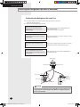
Performing the Refrigerant Gas Leak Test
Use tools for R410a to prevent the inflow of foreign substances and resist
against the internal pressure.
Pressure test with dry Nitrogen gas only.
Apply pressure to the liquid side pipe
and gas side pipe with Nitrogen gas of
4.1MPa(594.6psi).
If you apply pressure more than 4.1MPa(594.6psi), the
pipes may be damaged.
Apply pressure using pressure regulator.
Keep it for minimum 24 hours to check if the
pressure drops.
After applying Nitrogen gas, check the change of pressure
using pressure regulator.
If the pressure drops, check if there is gas
leak.
If the pressure is changed, apply soapy water to check the
leak. Check the pressure of the Nitrogen gas again.
Maintain 1.0MPa(145psi) of the pressure
before performing vacuum drying and check
further gas leak.
After checking first gas leak, maintain 1.0MPa(145psi) to
check further gas leak.
Manifold gauge
Low pressure side
High pressure side
Gas side pipe
Pressure
adjustment
valve
(mandatory)
Service port
Liquid side pipe
Nitrogen
gas
CAUTION
You may get injured when the joint on the high pressure side detaches and
the gas comes in contact with your body. Make sure to tighten the joint to
prevent such accidents.
E-20
FJM RD040MHXCA_IM_00000_E_2.23.10.indd 20
2010-2-24 19:57:32
ENGLISH
INSTALLING THE UNIT
Manifold gauge
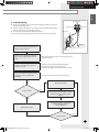
Vacuum Drying
Use the tools for R410a to prevent the inflow of foreign substances and resist
against the internal pressure.
Use the vacuum pump with the check valve to prevent pump oil from flowing
Low pressure side
backward while the vacuum pump is stopped.
Vacuum system to 5Torr (666.6Pa, 5mmHg, 0.0967psi).
Close the service valve of the liquid side pipe and gas side pipe completely.
High pressure
side
Gas side pipe
Vacuum
pump
Connect the manifold gauge to the liquid
side pipe and gas side pipe.
Liquid side pipe
Service port
Perform vacuum drying of the liquid side
pipe and gas side pipe using the vacuum
pump.
Make sure that install check valve to prevent pump oil from
flowing into the pipe.
Perform vacuum drying for 2 hours and
30 minutes or more.
The time of vacuum drying may differ depending on
the length of the pipe or outdoor temperature.
Perform vacuum drying for at least 2 hours and 30 minutes.
Close the valve after checking the vacuum
gauge pressure has reached at 5Torr
(0.0967psi).
Check the vacuum pressure using the vacuum gauge.
Check for gas leakage
Yes
Pressure Increase
Since there is water in pipeline, the pressure
increases and vacuum condition is broken.
Exert pressure using 0.05Mpa (7.25psi)
nitrogen.
No
Fill refrigeration agent
No
Vacuum desiccate again, to reach 5Torr
(666.6Pa, 5mmHg, 0.0967psi).
(2 hours and more)
Pressure Increase
Yes
E-21
FJM RD040MHXCA_IM_00000_E_2.23.10.indd 21
2010-2-24 19:57:32
INSTALLING THE UNIT
Installing the Refrigerant Pipe Work (Continued)
Selecting Additional Refrigerant Charge
Basic charge
The basic amount of refrigerant for outdoor unit charged in factory is :
Outdoor unit (Series)
Factory charge(kg(lb))
RD040MHXCA
RD050MHXCA
4.0(8.82)
Charge additional refrigerant according to the total length of the pipe.
Depends on the total length of the liquid side pipe.
Additional Charge (g) = {(L1(m)x20(g/m)) + (L2(m)x50(g/m))}
(oz) = {(L1(ft)x0.215(oz/ft)) + (L2(ft)x0.54(oz/ft))}
L1(m(ft)): Total length of liquid pipe Ø 6.35(Ø1/4)
L2(m(ft)): Total length of liquid pipe Ø 9.52(Ø3/8)
Refrigerant Charging
Additional charging
Additional Refrigerant calculation only related with liquid pipe length
Basic refrigerant for outdoor unit already has been charged
Additional charge calculation = (Sum of total length(m) of Φ9.52)x50g +
(Sum of total length(m) of Φ6.35)x20g
= (Sum of total length(ft) of Φ9.52)x0.54oz +
(Sum of total length(ft) of Φ6.35)x0.215oz
ex) a(Φ9.52)=40m(131.2ft), b+c+d(Φ9.52)=15m(49.2ft),e+f+g(Φ6.35)=15m(49.2ft)
Additional charge = 55mx50g + 15mx20g = 3050g
= 180.4ftx0.54oz + 49.2ftx0.215oz = 108oz
E-22
FJM RD040MHXCA_IM_00000_E_2.23.10.indd 22
2010-2-24 19:57:33
ENGLISH
INSTALLING THE UNIT
Adding Refrigerant
The R410a refrigerant is blended refrigerant. Add only liquid refrigerant.
Measure the quantity of the refrigerant depending on the length of the liquid
side pipe. Add fixed quantity of the refrigerant using a scale.
※ Adding the cooling refrigerant
Manifold gauge
Low pressure
side
High pressure
side
Gas side
Outdoor unit
Suction charging
Liquid side
Service valve
Scale
※ Adding the heating refrigerant
Manifold gauge
Low pressure
side
High pressure
side
Gas side
Scale
Outdoor unit
Suction charging
Liquid side
Service valve
Connect the manifold gage and purge the manifold gage.
Open the manifold gauge valve of the liquid side service valve and add the
liquid refrigerant.
If you cannot fully recharge the additional refrigerant while the outdoor unit
is stopped, use the key on the outdoor unit PCB to recharge the remaining
refrigerant. (Refer to page 32.)
Adding the cooling refrigerant
1) Press the function key for adding refrigerant in cooling mode.
2) After 20 minutes of operation, open the valve on gas side.
3) Open the valve for low pressure side on the manifold gage to recharge the
remaining refrigerant.
Adding the heating refrigerant
1) When recharging the heating refrigerant, connect the low pressure pipe from
manifold gage to the suction charging port.
2) Press the function key for adding refrigerant in heating mode.
3) After 20 minutes of operation, open the valve on suction charge port.
4) Open the valve for low pressure side on the manifold gage to recharge the
remaining refrigerant.
CAUTION
Open the gas side and liquid side service valve completely after charging the
refrigerant. (If you operate the air conditioner with the service valve closed,
the important parts may be damaged.)
FJM RD040MHXCA_IM_00000_E_2.23.10.indd 23
E-23
2010-2-24 19:57:34
INSTALLING THE UNIT
Installing the Refrigerant Pipe Work (Continued)
To Close the Valve Stem
Cap
1
Open the cap and turn the valve stem clockwise by using a hexagonal
wrench.
2
Tighten the valve stem until it reached the sealing edge.
Note
Do not apply excessive force to the valve stem and always use
special instruments. Otherwise, the contact surface between
valve stem and sealing edge can be damaged and refrigerant
can leak through this damaged surface.
If refrigerant would leak, turn the valve stem back by half and
tighten the valve stem again, then check the leakage. If there is
no leakage any more, tighten the valve stem entirely.
3
Tighten the cap securely.
Valve stem
Service
port
Sealing edge
To Open the Valve Stem
1
Remove the cap.
2
Turn the valve stem counterclockwise by using a hexagonal wrench.
3
Turn the valve stem until it is stopped.
4
Tighten the cap securely.
CAUTION
When you use the service port, always use a charging hose, too.
Check the leakage of refrigerant gas after tightening the cap.
Must use a spanner and wrench when you open/tighten the valve stem.
E-24
FJM RD040MHXCA_IM_00000_E_2.23.10.indd 24
2010-2-24 19:57:35
INSTALLING THE UNIT
ENGLISH
Electrical Connections
WARNING
Install the outdoor unit on a hard and even place that can support its weight.
- If the place cannot support its weight, the outdoor unit may fall down and it may cause injury.
T
he electric work must be done by service agent or similarly qualified persons according to national
wiring regulations and use only rated cable.
- If the capacity of the power cable is insufficient or electric work is not properly completed, electric
shock or fire may occur.
Make sure there is no leakage after installation.
- Toxic gas may generate when refrigerant gas contacts with fire.
Install the outdoor unit correctly according to the installation manual.
- An incorrect installation may cause a water leakage, electric shock or fire and so on.
T
he installation must be done by the manufacturer or its service agent or a similar qualified person in
order to avoid a hazard.
- Installation by an unqualified person may cause a water leakage, electric shock or fire and so on.
The unit must be plugged into an independent circuit if applicable or connect the power cable to the
auxiliary circuit breaker. An all pole disconnection from the power supply must be incorporated in the
fixed wiring with a contact opening of >3mm(1/8in).
Switch off the main circuit breaker and the branch circuit breaker before electric work.
Perform earthing work 3 without fail. An earthing resistance should be under 100Ω.
The protective earthing resistance can be applied in case of using ELCB (Earth Leakage Circuit
Breaker). When using an ELCB that has a tolerance limit as 100mA per second, the protective earthing
resistance is 250Ω in an electrical danger zone, else under 500Ω.
The input voltage of the indoor and outdoor unit should be within ±10% of the rated one.
For details of wiring, refer to the circuit diagram attached onto the outdoor unit.
The circuit diagram for wiring shows only the concept.
Do not connect the heater to the outdoor unit and do not install remodeled duct as you please.
- The capacity of the air conditioner may reduce and electric shock or fire may occur.
Install the power cable and communication cable of the indoor and outdoor unit at least 1.5m(5ft)
away from electric appliances.
- Noise may hear depending on the electric wave though the cables are installed away from electric
appliances.
Install the indoor unit away from lighting apparatus using the ballast.
- If you use the wireless remote control, it may not operate normally.
E-25
FJM RD040MHXCA_IM_00000_E_2.23.10.indd 25
2010-2-24 19:57:35
INSTALLING THE UNIT
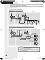
Electrical Connections (Continued)
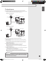
Overall System Configuration
Connection of the power cable (1 phase 2 wires)
Distribution board
1 phase
2 wires
208V-230V~
ELCB
Or
MCCB+
ELB
Outdoor unit
Indoor unit
1 phase
2 wires
208V-230V~
Or
MCCB+ ELCB
ELB
220V
Earth
Communication cable
Earth
Wired remote
controller
Connection of the power cable (1 phase 2 wires using Electronic Expansion Valve kit)
Distribution board
Outdoor unit
1 phase
2 wires
208V-230~
ELCB
Indoor unit
1 phase
2 wires
208V-230V~
Or
MCCB+ ELCB
ELB
Or
MCCB+
ELB
Wired remote
controller
Earth
EEV kit
Communication cable
CAUTION
Install cabinet panel near the outdoor unit for the convenience of
service and emergency operation off.
Make sure to install the circuit breaker with the over-current and
electric leakage protection.
E-26
FJM RD040MHXCA_IM_00000_E_2.23.10.indd 26
2010-2-24 19:57:35
ENGLISH
INSTALLING THE UNIT
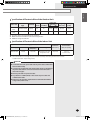
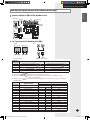
Specification of Electronic Wire of the Outdoor Unit
Power
Supply
Outdoor unit
Max/Min(V)
Max. MCCB+ELB(A)
Current or ELCB(A)
Power cable
(mm2(inch2))
CV
VV
Earth cable Max Length
(m (ft))
(mm2(inch2))
RD040MHXCA
208V-230V~/60Hz
Series
187/253
28.0
40
4(0.006) 6(0.009)
6(0.009)
18(59)
RD050MHXCA
208V-230V~/60Hz
Series
187/253
30.0
40
4(0.006) 6(0.009)
6(0.009)
18(59)
The power cable is not supplied with the air conditioner.
MCCB : Molded Case Circuit Breaker, ELB : Earth Leakage Breaker.
ELCB:Earth Leakage Circuit Breaker.
Specification of Electronic Wire of the Indoor Unit
Power Supply (1 Phase)
Power Supply
Max/Min(V)
Power cable
(mm2(inch2))
Max length
208-230V~/60Hz
187/253
2.5(0.0038)
Decided by power drop
among indoor units
Earth Cable
(mm2(inch2))
Communication
cable (mm2(inch2))
2.5(0.0038)
0.75~1.25
(0.0012~0.0019)
Select the thickness and length of power cable for total drop of electric pressure to be less than
10%(On 208V-230V~ lnput voltage basis).
CAUTION
You should connect the power cable into the power cable terminal and
fasten it with a clamp.
To protect the product from water and possible shock, you should keep
the power cable and the connection cord of the indoor and outdoor
units in the iron pipe.
Must keep the cable in a protection tube.
Keep distances of 50mm(2inch) or more between power cable and
communication cable.
Each indoor unit should be supplied between maximum and minimum
voltage values(253V~187V).
E-27
FJM RD040MHXCA_IM_32073_E_3.17.10.indd 27
2010-3-17 18:59:04
INSTALLING THE UNIT
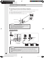
Electrical Connections (Continued)
Power Wiring and Communication Wiring Configuration
Be sure to run the power supply cable and the communication cable through electrical conduit as seen in the
picture.
Install the communication cable, indoor power cable and the main power cable in the cable tube.
Secure the cable tube to the outdoor knockout using the CD connector and bushing.
Arrange the cables as shown in the picture.
The diameter of the 6 knock-out holes is Ø27.8 mm(Ø1-3/32 inch).
(Inside)
Communication cable
(Outside)
Main power cable
CAUTION
Make a knockout hole by driving in a nail.
When installing the cables through the knockout hole, remove all
burrs and protect them with the protection tape.
Apply rust resisting paint around the hole.
1 phase 2 wires (208V-230V~)
1 phase 208V-230V~
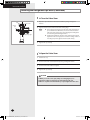
��
�����
���
Earth cable
(U-Trap)
Power cable
Communication cable
between indoor and
outdoor units
Earth
CAUTION
When removing the outer cover of the power cable, use the appropriate tools to prevent damaging
the inner cover.
Make sure to place the outer cover of the power cable and the communication cable, at least
20mm(3/4inch) into the electrical parts.
Communication wiring should be done separately from the power cable and other communication
cables.
E-28
FJM RD040MHXCA_IM_00000_E_2.23.10.indd 28
2010-2-24 19:57:36
ENGLISH
INSTALLING THE UNIT
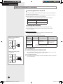
Installing the Transmitter (MIM-B13A)
RD040/050MHXCA MAIN PBA
MAIN + SUB Communication Line
DIP 1
DC12V
Supply
DC5V
Supply
Settings of Adapter Address
Channel 0
Turn off 12V, 5V Supply
Adapter Main PCB
Controlling Unit
Outdoor Unit
CAUTION
When installation is carried out, the distance between the first and last transmitter should be
kept within 1000m(3280.84ft).
Turn off the power supply before installation.
Follow the electric wiring safety standards when electrical wire is installed, and to avoid
danger to users, the wire should pass through the wall.
Installating the Operation Mode Selection Switch (MCM-C200)
Housing Connection Method:
When connecting the wire, as shown in the picture, push
down after inserting minus-driver in housing-home. (To
avoid pressure upon the coating part, only the exposed
section should be inserted)
Assembly
Drawing
Wire Diagram
Refrigeration
Blue
White
Automation
Red
Heating
Switch for Refrigeration &
Heating PCB
To Buy Electrical
Wire on the Spot
K5 (Refrigeration)
Automation
K6 (Heating)
Outdoor Unit
PCB
CAUTION
Operation mode selection switch cannot operate normally when improper connection occurs.
Carry out the installation at a position within 18m(59ft) of the outdoor unit, and apply safe
external connection only to the operation mode selection switch (MCM-C200).
Connection to any other switch extender is forbidden.
E-29
FJM RD040MHXCA_IM_00000_E_2.23.10.indd 29
2010-2-24 19:57:38
INSTALLING THE UNIT
Electrical Connections (Continued)
Connecting the Power Terminal
Connect the cables to the terminal board using the compressed ring terminal.
Connect the rated cables only.
Connect using a wrench which is able to apply the rated torque to the screws.
If the terminal is loose, fire may occur caused by arc.
If the terminal is connected too firmly, the terminal may be damaged.
Tightening Torque (kgf.cm(lb.ft))
M4
12.0~14.7(0.86~1.06)
M5
24.4~29.8(1.76~2.15)
Installing the Earth Wire
Earthing must be done by your installation specialist for your safety.
Use the earth wire by referring to the specification of the electric cable
for the outdoor unit.
Earthing the power cable
The standard of earthing may vary according to the rated voltage and
installation place of the air conditioner.
Earth the power cable according to the following.
When using the terminal for
earthing only
Earth terminal
Installation
place High humidity
Power
condition
Electrical
potential of lower
than 150V
Electrical
potential of
higher than 150V
When using earthing of the
switchboard
Distribution Board
Average humidity
Perform the
earthing work 3. Note 1)
Low humidity
Perform the earthing
work 2 if possible for
your safety. Note 2)
Must perform the earthing work 3. Note 1)
(In case of installing circuit breaker)
Note 1) Earthing work 3
Earthing must be done by your installation specialist.
Check if the earthing resistance is lower than 100Ω.
When installing a circuit breaker that can cut the electric circuit in case of a short
circuit, the allowable earthing resistance can be 30~500Ω.
Note 2) Earthing at dry place
The earthing resistance should be lower than 100Ω. (Even in worst case it should
be lower than 250Ω.)
E-30
FJM RD040MHXCA_IM_00000_E_2.23.10.indd 30
2010-2-24 19:57:40
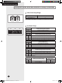
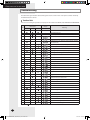
COMPLETING THE INSTALLATION
Setting the Option Switch and Function of the Keys
Display
Key
ENGLISH
Option Switches in PBA of the Outdoor Unit
※ Main PBA
Dip switch
Rotary
switch
Key Function of the Outdoor Unit PBA
※ Display
※ KEY
Check mode
RESET View mode
※ Function of KEY
Number of
pressing
K1 (Heating)
1
2
3
4
5
Adding refrigerant in heating mode (
Test operation for heating ( )
Heating Pump out operation ( )
Vacuum(All)(t 4) ( )
End of key operation
K2 (Cooling)
)
Adding refrigerant in cooling mode ( )
Test operation for cooling ( )
Cooling Pump down operation ( )
End of key operation
-
Adding refrigerant ( ,
): The operation for charging additional refrigerant
Test operation ( ,
): Checking the indoor and outdoor unit operation
Recovery of refrigerant ( ): Operation for collecting refrigerant to the outdoor unit when moving or
repairing the outdoor unit .
Refrigerant release ( ): Operation for releasing the refrigerant on the outdoor unit to the indoor unit pipes.
※ Function of K4
Number of
pressing
1
2
3
4
5
6
7
8
9
10
11
12
13
14
15
Display contents
Press for 5 seconds
Current frequency
Target frequency
Outdoor temperature
Discharge Temp
OLP Temp
Cond out Temp
Double pipe Out Tube Temp(Tsc)
High Pressure
Current Fan RPM
Double pipe EEV
Main EEV
Current
Number of connected indoor units
Number of operating indoor units
Total capacity of operating indoor units
FJM RD040MHXCA_IM_32073_E_4.06.10.indd 31
SEG 1
Display
SEG 2,3,4
SW version display
1
0, 3, 0
2
0, 3, 0
3
0, 3, 0
4
1, 0, 5
5
1, 0, 5
6
0, 4, 5
7
0, 4, 5
8
3, 2, 1
9
7, 0, 0
A
1, 8, 0
B
1, 5, 0
C
1, 5, 0
D
0, 1, 0
E
0, 1, 0
F
1, 2, 0
Contents
SW version
Display current frequency
30Hz
30˚C
105˚C
105˚C
45˚C
45˚C
3.21MPa
700RPM
180Step
1500Step (Full open position)
4/5HP: 30A(15x2)
10
10
120
E-31
2010-4-6 10:16:33
COMPLETING THE INSTALLATION
Setting the Option Switch and Function of the Keys (Continued)
Indoor Unit Setup Range
����
Outdoor unit
Maximum of connected indoor units
RD040MHXCA Series
RD050MHXCA Series
6
8
����
For example: Set the SW01 to '0' ans SW02 to ‘3’ if 3 indoor units are installed.
Tens digit
Unit digit
Dip Switch Setup
����
K5 K6 K7 K8
����
K9 K10K11 K12
����
K13 K14K15 K16
Switch No.
K5
Function (Communication Tracking)
ON
OFF
Set indoor unit address manually
Set indoor unit address automatically
Switch No.
K8
K7
Function (Cooling capacity compensation)
ON
ON
OFF
OFF
ON
OFF
ON
OFF
No Cooling Frequency compensation (Default)
Frequency compensation 105% (frequency*compensation value)
Frequency compensation 110% (frequency*compensation value)
Frequency compensation 115% (frequency*compensation value)
Switch No.
K9
K10
ON
ON
OFF
OFF
Function (Night silence)
ON
OFF
ON
OFF
Not use Night silence (Default)
Night silence Step_1
Night silence Step_2
Night silence Step_3
Switch No.
K11
K12
ON
ON
OFF
OFF
ON
OFF
ON
OFF
Function (Heating capacity compensation)
No high pressure target (Default)
High pressure target (standard -0.2MPa(-29psi))
High pressure target (standard -0.1MPa(-14.5psi))
High pressure target (standard +0.1MPa(+14.5psi))
Standard:30MPa(4351.14psi)
Switch No.
K13
K14
ON
ON
ON
OFF
Function (Current limit setting)
Current limit(Default)
Current limit(Option)
Maximum
running current
4HP
5HP
28A
26A
30A
28A
E-32
FJM RD040MHXCA_IM_32073_E_3.17.10.indd 32
2010-3-17 19:01:11
COMPLETING THE INSTALLATION
ENGLISH
Pump Down Procedure
Objective of Pump Down
For product repairs and indoor unit relocation, pump down operation must be done to collect the
refrigerant to the outdoor unit and minimize the leakage within system.
Cautions When Performing Pump Down
Product limits amount of refrigerant in the outdoor unit due to slim design.
Collect the majority of the refrigerant in the system in an empty refrigerant vessel and perform a
pump down operation with remaining refrigerant. Maximum amount of refrigerant is 5kg(11lb).
If the amount of refrigerant exceeds maximum allowable limit, increased pressure may cause
compressor trip or a burn out.
Pump Down Procedure
1
Fill an empty refrigerant before performing pump down operation.
2
Close the manifold gauge.
3
Close the liquid side service valve.
4
Press the K2 button on the outdoor unit PCB three times.
( will be displayed on outdoor unit PCB LED.)
5
Observe low pressure side using manifold gauge when the compressor moves.
6
When the pressure on low pressure side decrease below 0kg/cm2g(0psig),g close the gas side service
valve and end the pump down operation.
(To end the pump down operation, press the K2 button once more or press K3 button to reset.)
CAUTION
Use an exclusive rechargeable refrigerant vessel when collecting the refrigerant. Using modified
refrigerant vessel may cause explosion and cause damage or personal injury.
Note
Relocation of the air conditioner
Refer to this procedure when the unit is relocated.
Carry out the pump down procedure (refer to the details of ‘pump down’).
Collecting refrigerant may be hard, since multi type products exceeds allowable charging
amount of refrigerant in the outdoor unit to support long piping. (Refer to page 35.)
Remove the power cord.
Disconnect the assembly cable from the indoor and outdoor units.
Remove the flare nut connecting the indoor unit and the pipe.
At this time, cover the pipe of the indoor unit and the other pipe using a cap or vinyl plug to
avoid foreign material entering.
Disconnect the pipe connected to the outdoor unit.
At this time, cover the valve of the outdoor unit and the other pipe using a cap or vinyl plug
to avoid foreign material entering.
Make sure you do not bend the connection pipes in the middle and store together with the
cables.
Move the indoor and outdoor units to a new location.
Remove the mounting plate for the indoor unit and move it to a new location.
E-33
FJM RD040MHXCA_IM_00000_E_2.23.10.indd 33
2010-2-24 19:57:44
COMPLETING THE INSTALLATION
Pump Down Procedure (Continued)
Collecting Refrigerant in Refrigerant Vessel Before
Pump Down Operation
If the amount of refrigerant in the system exceeded the maximum allowable
limit, reduce the amount of the refrigerant by following the below
instruction before pump down operation.
1
Prepare an exclusive rechargeable refrigerant vessel, scale and a manifold
gauge.
2
Check the amount of refrigerant in the entire system.
3
Connect a refrigerant vessel to a outdoor unit and operated about 50% of the
indoor unit in cooling mode.
4
After 10 minutes of cooling operation, check the pressure on high pressure
side with the manifold gauge. If the pressure on the high pressure side is
over 30kg/cm2,g(426.7psig) reduce the number of operating indoor unit to
decrease the pressure below 30kg/cm2,g(426.7psig).
5
When the pressure becomes lower than 30kg/cm2,g(426.7psig) open the
manifold gauge valve which is connected to a liquid side. Then, open the
valve on the refrigerant vessel for the refrigerant to flow from the liquid side
pipe to a vessel.
6
Check the weight difference with the scale. When desire amount of the
refrigerant is collected on the vessel, close the valve and remove the manifold
gauge.
7
Make sure that the amount of the refrigerant in the vessel is about 50% of the
entire system.
8
Measure the amount of refrigerant correctly to not exceed amount of collected
refrigerant.
Outdoor unit
Gas side
R410a
Liquid side
Refrigerant
vessel valve
Valve
Valve
Scale
Manifold gauge
Service valve
E-34
FJM RD040MHXCA_IM_00000_E_2.23.10.indd 34
2010-2-24 19:57:44
ENGLISH
COMPLETING THE INSTALLATION
When refrigerant recovery is difficult due to the large amount of refrigerant
1
Prepare manifold gauge, scale and an empty refrigerant vessel.
2
As shown below, connect the middle hose of manifold gauge to the refrigerant
vessel and then connect the both ends of manifold gauge to the outdoor unit
service valve individually.
(Valve of refrigerant vessel and Low pressure side valve must be closed and
the high pressure side valve must be open.)
3
Start refrigerant recovery operation by pressing K2 button three times.
(Refer to page 31.)
4
After operating for 10 minutes, open the valve of refrigerant vessel and fill it
with refrigerant.
5
Close the valve of refrigerant vessel when sufficient refrigerant is filled.
6
Close the liquid service valve immediately. When the low pressure falls down
lower than 0, close the gas service valve.
7
Stop the operation by pressing reset button.
Manifold gauge
Low pressure side
High pressure side
Gas side pipe
An empty
refrigerant
vessel
Service port
Liquid side pipe
scale
E-35
FJM RD040MHXCA_IM_00000_E_2.23.10.indd 35
2010-2-24 19:57:44
COMPLETING THE INSTALLATION
Completing the Installation
Check the following after completing the installation.
Outdoor unit
Installation
Check the external surface and the inside of the outdoor unit.
Is there any possibility of short circuit?
Is the place well-ventilated and ensures space for service?
Is the outdoor unit fixed securely?
Check the external surface and the inside of the indoor unit.
Is the place well-ventilated and ensures space for service?
Check if the center of the indoor unit is ensured and it is installed horizontally.
Is total number of connecting indoor units in the allowable range?
Are the length and the difference between the refrigerant pipes within the allowable range?
Is the Y-joint properly installed?
Is the pipe properly insulated?
Is the quantity of the additional refrigerant correctly weighed in?
Indoor unit
Adding refrigerant
Check the drain pipe of the outdoor unit and the indoor unit.
Have you completed the drain test?
Is the drain pipe properly insulated?
Have you performed the earthing work 3 to the outdoor unit?
Is 2-core cable used?
Is the length of the wire is in the limited range?
Is the wiring route correct?
Installing the drain pipe
Installing the wiring
Setting ADDRESS
Are the ADDRESSES of the indoor and outdoor unit properly set?
Final Checks and Trial Operation
Turn on the outdoor unit 3 hours before the test operation to preheat the compressor. If the compressor is
not preheated, ‘CH’ will appear on the outdoor unit PCB.
Inspection Before Test Operation
1
Check the power cable and communication cable of the indoor and
outdoor unit.
2
Check the power supply between the outdoor unit and the cabinet panel.
Check the 208V-230V~power with the voltage meter.
3
Once the outdoor unit is turned on, it performs the tracking to check the
connected indoor unit and options.
Test Operation
1
Run the unit by KEY MODE or controller.
1st- Running all indoor units by KEY MODE
2nd- Each indoor unit run separately by controller
Inspect the compressor sound during the initial operation.
If roaring sound is heard, stop operation.
2
Check the indoor and outdoor units’ running status.
- Check indoor unit cooling and heating air flow
- Each indoor unit controls: air flow direction, air velocity
- Indoor and outdoor unit’s abnormal running noise
- Proper drainage from indoor unit in cooling mode
- Check detail running status using S-NET program.
3
Finish test.
4
Explain to the customer how to use the air conditioner following the user’s
manual.
E-36
FJM RD040MHXCA_IM_00000_E_2.23.10.indd 36
2010-2-24 19:57:45
COMPLETING THE INSTALLATION
ENGLISH
Final Checks and Trial Operation(Continued)
Filling Out the Installation Check Card and Storing
it Inside of the Outdoor Unit
The installation check card is enclosed in the installation manual.
Installation engineer should fill out the installation card faithfully.
- Basic contents such as installation date, name of engineer, contact number,
service company, etc.
- Additional contents such as model name of outdoor unit, remarks, refrigerant
calculation due to additional pipe, etc.
- Contents related indoor unit such as the place where indoor unit is installed,
model name of indoor unit, etc.
Store the installation check card inside of the outdoor unit and make sure not
lose it.
installation check
card
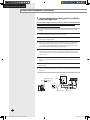
Pump Down Procedure (When removing the product)
1
Turn on the air conditioner and select Cool mode to run the compressor for 3
minutes.
2
Release the valve caps on High and Low pressure side.
3
Use L wrench to close the valve on the high pressure side.
4
Approximately 2 minutes after, close the valve on the low pressure side.
5
Stop operation of the air conditioner.
6
Disconnect the pipes.
E-37
FJM RD040MHXCA_IM_00000_E_2.23.10.indd 37
2010-2-24 19:57:46
COMPLETING THE INSTALLATION
Troubleshooting
The table below give indication about self diagnostic routine. Some of error code requires activities exclusively
for Authorized Service Center.
Outdoor Unit
If an error occurs during the operation, it is displayed on the outdoor unit PCB LED, both MAIN PCB and INVERTER PCB.
Main 7-seg
display
LED Display
No.
Meaning
Yellow
Green
Red
Error Number
-
Power off/VDD NG
-
Power ON reset(1sec)
3
4
1
2
-
Normal Operation
The number of indoor units error
5
Indoor and Outdoor Unit communication error
6
Communication error between outdoor unit Inv and Main
micom(1minute)
7
Outdoor temp sensor error(Short/Open)
8
Cond temp sensor error(Short/Open)
9
10
11
[Self-diagnosis] Cond sensor detachment
Discharge temp sensor error(Short/Open)
[Self-diagnosis] Discharge sensor detachment
Double pipe sensor error
12
13
OLP sensor error
Over-load prevention control
14
High pressure protection control
15
16
Discharge over temperature
ESC EEV Open
17
18
Heat Operation Prohibit 30°C (86°F )
19
Cool Operation Prohibit -10°C (14°F )
20
Fan_1 error
Fan_2 error
21
22
Detection error of misconnected communication cable
between indoor and outdoor unit
23
Comp Starting error
24
All electric current control
25
OLP temperature control compressor stop
26
IPM Over Current(O.C)
27
28
29
Comp limit error
DC-Link voltage under/over error
30
Comp rotation error
Current sensor error
DC-Link voltage sensor error
31
32
OTP error
33
AC Line Zero Cross Signal out
34
Off
Blink
GAS Leak error(Dual/Single)
On
E-38
FJM RD040MHXCA_IM_32073_E_4.06.10.indd 38
2010-4-6 10:22:47
ENGLISH
Memo
E-39
FJM RD040MHXCA_IM_00000_E_2.23.10.indd 39
2010-2-24 19:58:00
FJM RD040MHXCA_IM_00000_E_2.23.10.indd 40
2010-2-24 19:58:01
ENGLISH
INSTALLATION
MANUAL
FRANÇAIS
ESPAÑOL
RD040MHXCA Series
RD050MHXCA Series
Air Conditioner
E S F DB98-32073A(1)
FJM RD040MHXCA_IM_00000_E_2.23.10.indd 41
2010-2-24 19:58:01