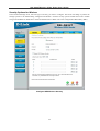
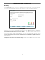
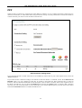
1
DSL-G624T
Wireless ADSL Router
User’s Guide
May 2005
Table Of Contents
About This User’s Guide ...............................................................................................................................................iii
BEFORE YOU START .......................................................................................................III
Installation Overview.......................................................................................................................................iii
The Setup Wizard ..........................................................................................................................................................iii
Packing List ................................................................................................................................................................... iv
Installation Requirements...............................................................................................................................iv
Introduction.......................................................................................................................................................1
Router Description and Operation .................................................................................................................................. 1
Standards Compatibility and Compliance ...................................................................................................................... 3
Front Panel Display ........................................................................................................................................................ 4
Rear Panel Connections.................................................................................................................................................. 5
Wireless LAN Basics ........................................................................................................................................6
About 802.11g Wireless ................................................................................................................................................. 7
HARDWARE INSTALLATION ............................................................................................8
Choosing the Best Location for Wireless Operation ....................................................................................8
Power on Router ............................................................................................................................................................. 9
Factory Reset Button ...................................................................................................................................................... 9
Wired Network Connections .......................................................................................................................................... 9
BASIC ROUTER CONFIGURATION ................................................................................12
Configuring IP Settings on Your Computer ................................................................................................................. 13
Access the Configuration Manager ............................................................................................................ 17
Login to Home Page ..................................................................................................................................................... 17
Configure the Router..................................................................................................................................... 18
Using the Setup Wizard ................................................................................................................................................ 19
HOME ................................................................................................................................27
Wireless LAN Setup....................................................................................................................................... 27
Configure Basic Wireless Settings ............................................................................................................................... 28
Wireless Security .......................................................................................................................................................... 28
WEP Encryption ........................................................................................................................................................... 30
Configure WAN Connection ......................................................................................................................... 33
PPPoE and PPPoA Connection for WAN .................................................................................................................... 34
Dynamic IP Address Connection for WAN.................................................................................................................. 36
Bridged Connection for WAN...................................................................................................................................... 38
Static IP Address for Connection WAN ....................................................................................................................... 39
LAN IP Settings.............................................................................................................................................. 43
DHCP Server Settings for the LAN .............................................................................................................. 44
Static IP Settings for the LAN ...................................................................................................................................... 45
DNS Server Settings ..................................................................................................................................................... 46
Dynamic DNS ................................................................................................................................................. 47
Save Settings and Reboot ............................................................................................................................ 48
ADVANCED ROUTER MANAGEMENT ...........................................................................49
UPnP............................................................................................................................................................................. 50
Virtual Server ............................................................................................................................................................... 51
LAN Clients.................................................................................................................................................................. 53
SNMP ........................................................................................................................................................................... 54
Filters............................................................................................................................................................................ 55
Bridge Filters ................................................................................................................................................................ 57
Routing ......................................................................................................................................................................... 58
DMZ ............................................................................................................................................................................. 59
Firewall........................................................................................................................................................................ 60
RIP................................................................................................................................................................................ 61
PPP ............................................................................................................................................................................... 62
ADSL............................................................................................................................................................................ 63
ATM VCC .................................................................................................................................................................... 64
QoS ............................................................................................................................................................................... 65
Wireless Management .................................................................................................................................................. 66
Wireless Performance................................................................................................................................................... 67
TOOLS ..............................................................................................................................68
Change System Password ............................................................................................................................................. 69
Remote Web Management and Telnet Access ............................................................................................................. 69
Time.............................................................................................................................................................................. 70
Remote Log .................................................................................................................................................................. 71
System .......................................................................................................................................................................... 72
Firmware....................................................................................................................................................................... 73
Ping Test (Miscellaneous) ............................................................................................................................................ 74
Test ............................................................................................................................................................................... 75
Status Information ........................................................................................................................................................ 76
Device Information Display.......................................................................................................................................... 77
DHCP Clients ............................................................................................................................................................... 78
Log................................................................................................................................................................................ 79
Traffic ........................................................................................................................................................................... 80
ADSL............................................................................................................................................................................ 81
TECHNICAL SPECIFICATIONS .......................................................................................82
IP ADDRESS SETUP ........................................................................................................84
IP CONCEPTS ..................................................................................................................86
MICRO FILTERS AND SPLITTERS..................................................................................88
DSL-G624T Wireless A DSL Router User’s Guide
About This User’s Guide
This user’s guide provides instructions on how to install the DSL-G624T Wireless ADSL Router and use it to provide
Internet access for an Ethernet or 802.11g/802.11b wireless LAN.
If you are using a computer with a functioning Ethernet port, the quickest and easiest way to set up the DSL-G624T is
to insert the Installation CD into the CD-ROM drive of your computer and follow the instructions provided in the
Quick Installation Guide.
Before You Start
Please read and make sure you understand all the prerequisites for proper installation of your new Router. Have all the
necessary information and equipment on hand before beginning the installation.
Installation Overview
The procedure to install the Router can be described in general terms in the following steps:
1.
2.
3.
4.
Gather information and equipment needed to install the device. Before you begin the actual installation make
sure you have all the necessary information and equipment.
Install the hardware, connect the cables to the device and connect the power adapter.
Check the IP settings on your computer and change them if necessary so the computer can access the webbased software built into the Router.
Use the web-based management software to configure the device to suit the requirements of your ADSL
service and wireless LAN.
The Setup Wizard
Once you access the web interface use the Setup Wizard to configure your Internet connection.
iii
DSL-G624T Wireless A DSL Router User’s Guide
Packing List
Open the shipping carton and carefully remove all items. Make sure that you have the items listed here.
1.
One DSL-G624T 802.11g Wireless ADSL Ethernet Router
2.
One CD-ROM containing the User’s Guide
3.
One twisted-pair telephone cable used for ADSL connection
4.
One straight-through Ethernet cable
5.
One AC power adapter suitable for your electric service
6.
One Quick Installation Guide
Installation Requirements
In order to establish a connection to the Internet it will be necessary to provide information to the Router that will be
stored in its memory. For some users, only their account information (Username and Password) is required. For others,
various parameters that control and define the Internet connection will be required. You can print out the two pages
below and use the tables to list this information. This way you have a hard copy of all the information needed to setup
the Router. If it is necessary to reconfigure the device, all the necessary information can be easily accessed. Be sure to
keep this information safe and private.
Low Pass Filters
Since ADSL and telephone services share the same copper wiring to carry their respective signals, a filtering
mechanism may be necessary to avoid mutual interference. A low pass filter device can be installed for each telephone
that shares the line with the ADSL line. These filters are easy to install passive devices that connect to the ADSL device
and/or telephone using standard telephone cable. Ask your service provider for more information about the use of low
pass filters with your installation.
Operating Systems
The DSL-G624T uses an HTML-based web interface for setup and management. The web configuration manager may
be accessed using any operating system capable of running web browser software, including Windows 98 SE, Windows
ME, Windows 2000, and Windows XP.
Web Browser
Any common web browser can be used to configure the Router using the web configuration management software. The
program is designed to work best with more recently released browsers such as Opera, Microsoft Internet Explorer®
version 5.0, Netscape Navigator® version 4.7, or later versions. The web browser must have JavaScript enabled.
JavaScript is enabled by default on many browsers. Make sure JavaScript has not been disabled by other software (such
as virus protection or web user security packages) that may be running on your computer.
Ethernet Port (NIC Adapter)
Any computer that uses the Router must be able to connect to it through the Ethernet port on the Router. This
connection is an Ethernet connection and therefore requires that your computer be equipped with an Ethernet port as
well. Most notebook computers are now sold with an Ethernet port already installed. Likewise, most fully assembled
desktop computers come with an Ethernet NIC adapter as standard equipment. If your computer does not have an
Ethernet port, you must install an Ethernet NIC adapter before you can use the Router. If you must install an adapter,
follow the installation instructions that come with the Ethernet NIC adapter.
Wireless LAN Configuration
Wireless LAN settings for 802.11g and 802.11b wireless operation must be enabled using the Setup Wizard before it
can be configured. Basic wireless settings including the Channel and SSID can be configured through the Setup Wizard.
Advanced wireless security settings can also be configured with the Setup Wizard.
iv
DSL-G624T Wireless A DSL Router User’s Guide
Security for wireless communication can be accomplished in a number of ways. The DSL-G624T supports WEP, WPA
and WPA -PSK.
Additional Software
It may be necessary to install software on your computer that enables the computer to access the Internet. Additional
software must be installed if you are using the device a simple bridge. For a bridged connection, the information needed
to make and maintain the Internet connection is stored on another computer or gateway device, not in the Router itself.
If your ADSL service is delivered through a PPPoE, PPPoA or Static IP connection, the information needed to establish
and maintain the Internet connection can be stored in the Router. In this case, it is not necessary to install software on
your computer. It may however be necessary to change some settings in the device, including account information used
to identify and verify the connection.
Information you will need from your ADSL service provider:
Username
This is the Username used to log on to your ADSL service
provider’s network. It is commonly in the form − [email protected].
Your ADSL service provider uses this to identify your account.
Password
This is the Password used, in conjunction with the Username
above, to log on to your ADSL service provider’s network. This
is used to verify the identity of your account.
These settings describe the method your ADSL service
provider uses to transport data between the Internet and your
computer. Most users will use the default settings. You may
need to specify one of the following WAN Setting and
Connection Type configurations (Connection Type settings
listed in parenthesis):
WAN Setting /
Connection Type
PPPoE/PPoA (PPPoE LLC, PPPoA LLC or PPPoA VC-MUX)
Bridge Mode (1483 Bridged IP LLC or
1483 Bridged IP VC-MUX)
Static IP Address (Bridged IP LLC, 1483 Bridged IP VC-MUX,
1483 Routed IP LLC, 1483 Routed IP VC-MUX or IPoA)
Dynamic IP Address (1483 Bridged IP LLC or 1483 Bridged IP
VC-MUX)
Default = PPPoE/PPPoA (PPPoE LLC)
VPI
Most users will not be required to change this setting. The
Virtual Path Identifier (VPI) is used in conjunction with the
Virtual Channel Identifier (VCI) to identify the data path
between your ADSL service provider’s network and your
computer. If you are setting up the Router for multiple virtual
connections, you will need to configure the VPI and VCI as
instructed by your ADSL service provider for the additional
connections. This setting can be changed in the WAN menu of
the web management interface. Default value = 8
VCI
Most users will not be required to change this setting. The
Virtual Channel Identifier (VCI) used in conjunction with the VPI
to identify the data path between your ADSL service provider’s
network and your computer. If you are setting up the Router for
multiple virtual connections, you will need to configure the VPI
and VCI as instructed by your ADSL service provider for the
additional connections. This setting can be changed in the
WAN menu of the web management interface. Default value =
35
v
Record info
here
DSL-G624T Wireless A DSL Router User’s Guide
Note
The Setup Wizard can be used to configure the Internet connection for most users. If you are
using a PPPoE or PPPoA type connection use the Setup Wizard to establish the Internet
connection.
Information you will need about your DSL-G624T ADSL Router:
Username
This is the Username needed access the Router’s
management interface. When you attempt to connect to
the device through a web browser you will be prompted
to enter this Username. The default Username for the
Router is admin. The user cannot change this.
Password
This is the Password you will be prompted to enter
when you access the Router’s management interface.
The default Password is admin. The user may change
this.
LAN IP addresses for
the DSL-G624T
This is the IP address you will enter into the Address
field of your web browser to access the Router’s
configuration graphical user interface (GUI) using a
web browser. The default IP address is 192.168.1.1.
This may be changed to suit any IP address scheme
the user desires. This address will be the base IP
address used for DHCP service on the LAN when
DHCP is enabled.
LAN Subnet Mask for
the DSL-G624T
This is the subnet mask used by the DSL-G624T, and
will be used throughout your LAN. The default subnet
mask is 255.255.255.0. This can be changed later.
Record info here
Information you will need about your LAN or computer:
Ethernet NIC
If your computer has an Ethernet NIC, you can
connect the DSL-G624T to this Ethernet port using an
Ethernet cable. You can also use the Ethernet ports
on the DSL-G624T to connect to other computer or
Ethernet devices.
DHCP Client status
Your DSL-G624T ADSL Router is configured, by
default, to be a DHCP server. This means that it can
assign an IP address, subnet mask, and a default
gateway address to computers on your LAN. The
default range of IP addresses the DSL-G624T will
assign are from 192.168.1.2 to 192.168.1.254. Your
computer (or computers) needs to be configured to
Obtain an IP address automatically (that is, they
need to be configured as DHCP clients.)
Record info here
It is recommended that your collect and record this information here, or in some other secure place, in case you have to
re-configure your ADSL connection in the future.
Once you have the above information, you are ready to setup and configure your DSL-G624T ADSL Router.
vi
DSL-G624T Wireless A DSL Router User’s Guide
Introduction
This section provides a brief description of the Router, its associated technologies and a list of Router features.
Router Description and Operation
The DSL-G624T Router is designed to provide a simple and cost-effective ADSL Internet connection for a private
Ethernet or 802.11g/802.11b wireless network. The Router combines high-speed ADSL Internet connection, IP routing
for the LAN and wireless connectivity in one package.
The Router is easy to install and use. The DSL-G624T connects to an Ethernet LAN or computers via standard Ethernet
ports. The ADSL connection is made using ordinary telephone line with standard connectors. Multiple workstations can
be networked and connected to the Internet using a single Wide Area Network (WAN) interface and single global IP
address. The advanced security enhancements, packet filtering and port redirection, can help protect your network from
potentially devastating intrusions by malicious agents from outside your network.
ADSL
Asymmetric Digital Subscriber Line (ADSL) is a broadband network technology that utilizes standard twisted-pair
copper wire telephone lines to enable broadband high-speed digital data transmission and bandwidth hungry
applications for business and residential customers.
ADSL routers and modems provide faster downloads and more reliable connectivity to the user without loss of quality
or disruption of voice/fax telephone capabilities.
ADSL service operates at speeds of up to 8 Mbps downstream and up to 640 Kbps upstream. A secure dedicated pointto-point connection is established between the user and the central office of the service provider.
802.11g Wireless
The embedded 802.11g wireless access point provides Internet access and connectivity to the Ethernet for 802.11g and
802.11b wireless workstations. IEEE 802.11g is fully compatible with IEEE 802.11b wireless devices. The 802.11g
standard supports data transfer rates of up to 54 Mbps. The Router’s wireless access point supports common security
protocols used for wireless LAN including WEP encryption, 802.1x and WPA.
Router Features
The DSL-G624T Wireless ADSL Router utilizes the latest ADSL enhancements to provide a reliable Internet portal
suitable for most small to medium sized offices. DSL-G624T advantages include:
•
802.11g Wireless Access Point – The built-in 802.11g wireless access point connects 802.11g and 802.11b
wireless devices to the Internet and the Ethernet.
•
PPP (Point-to-Point Protocol) Security – The DSL-G624T ADSL Router supports PAP (Password
Authentication Protocol) and CHAP (Challenge Handshake Authentication Protocol) for PPP connections.
•
DHCP Support – Dynamic Host Configuration Protocol automatically and dynamically assigns al LAN IP settings
to each host on your network. This eliminates the need to reconfigure every host whenever changes in network
topology occur.
•
Network Address Translation (NAT) – For small office environments, the DSL-G624T allows multiple users on
the LAN to access the Internet concurrently through a single Internet account. This provides Internet access to
everyone in the office for the price of a single user.
NAT improves network security in effect by hiding the private network behind one global and visible IP address.
NAT address mapping can also be used to link two IP domains via a LAN-to-LAN connection.
•
TCP/IP (Transfer Control Protocol/Internet Protocol) – The DSL-G624T supports TCP/IP protocol, the
language used for the Internet. It is compatible with access servers manufactured by major vendors.
1
DSL-G624T Wireless A DSL Router User’s Guide
•
RIP-1/RIP-2 – The DSL-G624T supports both RIP-1 and RIP-2 exchanges with other routers. Using both versions
lets the Router to communicate with all RIP enabled devices.
•
Static Routing – This allows you to select a data path to a particular network destination that will remain in the
routing table and never “age out”. If you wish to define a specific route that will always be used for data traffic
from your LAN to a specific destination within your LAN (for example to another router or a server) or outside
your network (to a ISP defined default gateway for instance).
•
Default Routing – This allows you to choose a default path for incoming data packets for which the destination
address is unknown. This is particularly useful when if the Router functions as the sole connection to the Internet.
•
ATM (Asynchronous Transfer Mode) – The DSL-G624T supports Bridged Ethernet over ATM (RFC1483), IP
over ATM (RFC1577) and PPP over ATM (RFC 2364).
•
Precise ATM Traffic Shaping – Traffic shaping is a method of controlling the flow rate of ATM data cells. This
function helps to establish the Quality of Service for ATM data transfer.
•
G.hs (Auto-handshake) – This allows the Router to automatically choose either the G.lite or G.dmt ADSL
connection standards.
•
High Performance – Very high rates of data transfer are possible with the Router. Up to eight Mbps downstream
bit rate using the G.dmt standard.
•
Full Network Management – The DSL-G624T incorporates SNMP (Simple Network Management Protocol)
support for web-based management and text-based network management via an RS-232 or Telnet connection.
•
Telnet Connection – The Telnet enables a network manager to access the Router’s management software
remotely.
•
Easy Installation – The DSL-G624T uses a web-based graphical user interface program for convenient
management access and easy set up. Any common web browser software can be used to manage the Router.
2
DSL-G624T Wireless A DSL Router User’s Guide
Standards Compatibility and Compliance
The DSL-G624T complies with or is compatible with the following standards as recognized by their respective
agencies.
•
ITU G.992.2 (G.lite) compliant
•
ITU-T Rec. I.361 compliant
•
RFC 791 Internet Protocol compliant
•
RFC 792 UDP compliant
•
RFC 826 Address Resolution Protocol compliant (ARP) compliant
•
RFC 1058 Routing Information Protocol (RIP) compliant
•
RFC 1213 MIB II for IP compliant
•
RFC 1334 PPP Authentication Protocol compliant
•
RFC 1389 Routing Information Protocol 2 (RIP2) compliant
•
RFC 1483 IP over AAL5/ Bridged Ethernet over AAL5 compliant
•
RFC 1557 Classical IP over ATM (IPoA) compliant
•
RFC 1661 Point to Point Protocol (PPP) compliant
•
RFC 1877 Automatic IP assignment compliant
•
RFC 1994 Challenge Handshake Authentication Protocol compliant
•
Supports RFC 2131 and RFC 2132 DHCP functions including: automatic assignment of IP address, use of subnet
mask and default gateway and provision of DNS server address for all hosts
•
RFC 2364 PPP over ATM compliant (PPPoA) compliant
•
RFC 2516 PPP over Ethernet compliant (PPPoE) compliant
•
RFC 2684 Bridged/Routed Ethernet over ATM compliant
•
IEEE 802.3 compliant
•
IEEE 802.3u compliant
•
IEEE 802.1d compliant
•
IEEE 802.11g compliant
•
IEEE 802.3x compliant
•
Embedded web server support
•
Supports Dynamic Learning
•
Supports Static Routing
•
Supports NAPT for up to 4096 connections
•
Supports DHCP for up to 253 hot connections
•
Supports IGMP
•
Supports ATM Forum UNI 3.1/4.0
•
Supports ATM VCC (Virtual Channel Circuit) for up to eight sessions
•
Supports TELNET and TFTP
•
Supports back pressure for half-duplex
3
DSL-G624T Wireless A DSL Router User’s Guide
Front Panel Display
Place the Router in a location that permits an easy view of the LED indicators on the front panel.
The LED indicators on the front panel include the Power, Status, ADSL and WLAN and Ethernet (1-4) Link/Act
indicators. The ADSL, WLAN and Ethernet indicators monitor link status and activity (Link/Act).
Power
Steady green light indicates the unit is powered on. When the device is
powered off this remains dark.
Status
Lights steady green during power on self-test (POST). Once the
connection status has been settled, the light will blink green. If the
indicator lights steady green after the POST, the system has failed and
the device should be rebooted.
ADSL (Link/Act)
Steady green light indicates a valid ADSL connection. This will light
after the ADSL negotiation process has been settled. A blinking green
light indicates activity on the WAN (ADSL) interface.
WLAN (Link/Act)
Steady green light indicates a wireless connection. A blinking green
light indicates activity on the WLAN interface.
Ethernet (Link/Act) 1 - 4
A solid green light indicates a valid link on startup. This light will blink
when there is activity currently on the Ethernet ports.
4
DSL-G624T Wireless A DSL Router User’s Guide
Rear Panel Connections
All cable connections to the Router are made at the rear panel. Connect the power adapter here to power on the Router.
Use the Reset button to restore the settings to the factory default values in the next chapter for instructions on using the
reset button).
Antenna
Reset button
ADSL port
For wireless
operation, mount
the antenna on
the threaded
antenna post.
To manually
reset, depress
button with the
power on for at
least seven
seconds
Use the ADSL
cable to connect
to the your
telephone line
(RJ-11 port)
Ethernet ports
Use the Ethernet ports
to connect the Router
to your Ethernet LAN
or Ethernet devices
Note
Power insert
Use the adapter
shipped with the
Router to
connect to
power source
To manually reboot the Router, disconnect and then reconnect the
power.
5
DSL-G624T Wireless A DSL Router User’s Guide
Wireless LAN Basics
Some basic understanding of 802.11b/g wireless technology and terminology is useful when you are setting up the
Router or any wireless access point. If you are not familiar with wireless networks please take a few minutes to learn
the basics.
Radio Transmission
Wireless LAN or WLAN devices use electromagnetic waves within a broad, unlicensed range of the radio spectrum to
transmit and receive radio signals. When a wireless access point is present, it becomes a base station for the WLAN
nodes in its broadcast range. WLAN nodes transmit digital data using FM (frequency modulation) radio signals. WLAN
devices generate a carrier wave and modulate this signal using various techniques. Digital data is superimposed onto the
carrier signal. This radio signal carries data to WLAN devices within range of the transmitting device. The antennae of
WLAN devices listen for and receive the signal. The signal is demodulated and the transmitted data extracted. The
transmission method used by the access point is called Direct Sequence Spread Spectrum (DSSS) and operates in a
range of the radio spectrum between 2.4GHz and 2.5GHz for transmission. See the technical specifications for more
details on wireless operation.
Range
Range should not be a problem in most homes or small offices. If you experience low or no signal strength in some
areas, consider positioning the Router in a location between the WLAN devices that maintains a roughly equal straightline distance to all devices that need to access the Router through the wireless interface. Adding more 802.11g access
points to rooms where the signal is weak can improve signal strength. Read the section about placement of the Router
titled Location in the next chapter, Hardware Installation, for more information.
SSID
Wireless networks use an SSID (Service Set Identifier) to allow wireless devices to roam within the range of the
network. Wireless devices that wish to communicate with each other must use the same SSID. Several access points
can be set up using the same SSID so that wireless stations can move from one location to another without losing
connection to the wireless network.
The DSL-G624T operates in Infrastructure mode. It controls network access on the wireless interface in its broadcast
area. It will allow access to the wireless network to devices using the correct SSID after a negotiation process takes
place. By default he DSL-G624T broadcasts its SSID so that any wireless station in range can learn the SSID and ask
permission to associate with it. Many wireless adapters are able to survey or scan the wireless environment for access
points. An access point in Infrastructure mode allows wireless devices to survey that network and select an access point
with which to associate. You may disable SSID broadcasting in the web manager’s wireless menu.
Wireless Security
Various security options are available on the DSL-G624T including open or WEP and WPA (including WPA-PSK).
Authentication may use an open system or a shared key. For details on these methods and how to use them, please read
the wireless LAN configuration information in chapters 3 (Basic Router Configuration) and 4 (Advanced Router
Configuration) below.
6
DSL-G624T Wireless A DSL Router User’s Guide
About 802.11g Wireless
Today's 11-megabits-per-second 802.11b wireless networks are fine for broadband Internet access (which typically tops
out at about 1 mbps) but rather slow for large internal file transfers or streaming video. However, 54-mbps, corporateoriented 802.11a is expensive--and because its radio uses the 5-GHz band and 802.11b uses the 2.4-GHz band,
upgrading to an 802.11a network means either scrapping 802.11b gear or buying even-pricier hardware that can support
both standards.
But 802.11g promises the same speed as 802.11a and the ability to coexist with 802.11b equipment on one network,
since it too uses the 2.4-GHz band.
802.11g is an extension to 802.11b, the basis of many wireless LANs in existence today. 802.11g will broaden
802.11b's data rates to 54 Mbps within the 2.4 GHz band using OFDM (orthogonal frequency division multiplexing)
technology. Because of backward compatibility, an 802.11b radio card will interface directly with an 802.11g access
point (and vice versa) at 11 Mbps or lower depending on range. You should be able to upgrade the newer 802.11b
access points to be 802.11g compliant via relatively easy firmware upgrades.
Similar to 802.11b, 802.11g operates in the 2.4GHz band, and the transmitted signal uses approximately 30MHz, which
is one third of the band. This limits the number of non-overlapping 802.11g access points to three, which is the same as
802.11b.
7
DSL-G624T Wireless A DSL Router User’s Guide
Hardware Installation
The DSL-G624T maintains three separate interfaces, an Ethernet LAN, a wireless LAN and an ADSL (WAN) interface.
Place the Router in a location where it can be connected to the various devices as well as to a power source. The Router
should not be located where it will be exposed to moisture or excessive heat. Make sure the cables and power cord are
placed safely out of the way so they do not create a tripping hazard. As with any electrical appliance, observe common
sense safety procedures.
The Router can be placed on a shelf or desktop, ideally you should be able to see the LED indicators on the front if you
need to view them for troubleshooting.
Choosing the Best Location for Wireless Operation
Many environmental factors can affect the effective wireless function of the DSL-G624T. If this is your first time
setting up a wireless network device, read and consider the points listed below.
The access point can be placed on a shelf or desktop, ideally you should be able to see the LED indicators on the front if
you need to view them for troubleshooting.
Designed to go up to 100 meters indoors and up to 300 meters outdoors, Wireless LAN lets you access your network
from anywhere you want. However, the number of walls, ceilings, or other objects that the wireless signals must pass
through can limit signal range. Typical ranges vary depending on the types of materials and background RF noise in
your home or business. For optimum range and signal strength, use these basic guidelines:
1.
Minimize the number of walls and ceilings between access points and clients:
The signal emitted from Wireless LAN devices can penetrate through ceilings and walls. However, each wall
or ceiling can reduce the range of Wireless LAN devices from 1 to 30M. Position your wireless devices so that
the number of walls or ceilings obstructing the signal path is minimized.
2.
Consider the direct line between access points and workstations: A wall that is 0.5 meters thick, at a 45degree angle appears to be almost 1 meter thick. At a 2-degree angle, it is over 14 meters thick. Be careful to
position access points and client adapters so the signal can travel straight through (90º angle) a wall or ceiling
for better reception.
3.
Building Materials make a difference: Buildings constructed using metal framing or doors can reduce
effective range of the device. If possible, position wireless devices so that their signal can pass through drywall
or open doorways, avoid positioning them so that their signal must pass through metallic materials. Poured
concrete walls are reinforced with steel while cinderblock walls generally have little or no structural steel.
4.
Position the antennas for best reception. Play around with the antenna position to see if signal strength
improves. Some adapters or access points allow the user to judge the strength of the signal.
5.
Keep your product away (at least 1-2 meters) from electrical devices:
Position wireless devices away from electrical devices that generate RF noise such as microwave ovens,
monitors, electric motors, etc.
8
DSL-G624T Wireless A DSL Router User’s Guide
Power on Router
CAUTION: The Router must be used with the power adapter included with the device.
To power on the Router:
1.
Insert the AC Power Adapter cord into the power receptacle located on the rear panel of the Router and plug the
adapter into a suitable nearby power source.
2.
You should see the Power LED indicator light up and remain lit. The Status LED should light solid green and begin
to blink after a few seconds.
3.
If the Ethernet port is connected to a working device, check the Ethernet Link/Act LED indicators to make sure the
connection is valid. The Router will attempt to establish the ADSL connection, if the ADSL line is connected and
the Router is properly configured this should light up after several seconds. If this is the first time installing the
device, some settings may need to be changed before the Router can establish a connection.
Factory Reset Button
The Router may be reset to the original factory default settings by depressing the reset button for a few seconds while
the device is powered on. Use a ballpoint or paperclip to gently push down the reset button. Remember that this will
wipe out any settings stored in flash memory including user account information and LAN IP settings. The device
settings will be restored to the factory default IP address 192.168.1.1 and the subnet mask is 255.255.255.0, the default
management Username is admin and the default Password is admin.
Wired Network Connections
Wired network connections are provided through the ADSL port and the four Ethernet ports on the back of the Router.
See the Rear Panel diagram above and the illustrations below for examples.
Connect ADSL Line
Use the ADSL cable included with the Router to connect it to a telephone wall socket or receptacle. Plug one end of the
cable into the ADSL port (RJ-11 receptacle) on the rear panel of the Router and insert the other end into the RJ-11 wall
socket. If you are using a low pass filter device, follow the instructions included with the device or given to you by your
service provider. The ADSL connection represents the WAN interface, the connection to the Internet. It is the physical
link to the service provider’s network backbone and ultimately to the Internet.
Connect Router to Ethernet
The Router may be connected to a single computer or Ethernet device through the 10/100 BASE-TX Ethernet port on
the rear panel. Any connection to an Ethernet concentrating device such as a switch or hub must operate at a speed of
10/100 Mbps only. When connecting the Router to any Ethernet device that is capable of operating at speeds between
0~100Mbps, be sure that the device has auto-negotiation (NWay) enabled for the connecting port.
Use standard twisted-pair cable with RJ-45 connectors. The RJ-45 port on the Router is a crossed port (MDI-X). Follow
standard Ethernet guidelines when deciding what type of cable to use to make this connection. When connecting the
Router directly to a PC or server use a normal straight-through cable. You should use a crossed cable when connecting
the Router to a normal (MDI-X) port on a switch or hub. Use a normal straight-through cable when connecting it to an
uplink (MDI-II) port on a hub or switch.
The rules governing Ethernet cable lengths apply to the LAN to Router connection. Be sure that the cable connecting
the LAN to the Router does not exceed 100 meters.
9
DSL-G624T Wireless A DSL Router User’s Guide
Hub or Switch to Router Connection
Connect the Router to an uplink port (MDI-II) on an Ethernet hub or switch with a straight-through cable as shown in
the diagram below:
If you wish to reserve the uplink
port on the switch or hub for
another device, connect to any on
the other MDI-X ports (1x, 2x, etc.)
with a crossed cable.
Computer to Router Connection
You can connect the Router
directly to a 10/100BASE-TX
Ethernet adapter card (NIC)
installed on a PC using the Ethernet
cable provided as shown in this
diagram.
10
DSL-G624T Wireless A DSL Router User’s Guide
The illustration below shows the DSL-G624T connected to Ethernet LAN devices, Wireless LAN devices and the
Internet.
11
DSL-G624T Wireless A DSL Router User’s Guide
Basic Router Configuration
The first time you setup the Router it is recommended that you configure the WAN connection using a single computer
making sure that both the computer and the Router are not connected to the LAN. Once the WAN connection is
functioning properly, you may continue to make changes to Router configuration including IP settings and DHCP setup.
This chapter is concerned mainly with using your computer to configure the WAN connection. Instructions are also
provided for basic Wireless LAN configuration. The following chapter describes how to set up the advanced features of
the Router.
Configuration Summary
1.
Connect to the Router To configure various settings used by the Router for Internet and Wireless LAN access
it is first necessary to access the Router’s management HTML-based interface. This is done using an ordinary
web browser. Your computer must be able to “see” the Router before it can manage it using a browser. If the
Router is in the same “neighborhood” or subnet as the Router, you should be able to access the management
software. Therefore you must first make sure your computer has IP settings that place it in the same subnet as
the Router. The easiest way to make sure your computer has the correct IP settings is to configure it to use the
DHCP server in the Router. The DHCP server will automatically enable your computer to use a browser to
manage the Router. The next section describes how to change the IP configuration for a computer running a
Windows operating system to be a DHCP client. If you are running another operating system, make sure your
computer is configured as a DHCP client so it can automatically obtain IP settings from the Router. Some
operating systems will automatically select the best IP settings. Consult the user manual for the operating
system (OS) if you are unsure.
2.
Configure the Internet (WAN) Connection Most users will be able to complete this process using the Setup
Wizard. The Setup Wizard can be launched once you have successfully connected with the Router’s
management software. There are different methods used to establish the WAN connection to the service
provider’s network and ultimately to the Internet. Your Router may already have most of the settings
configured by default. However you will probably at least have to type in a user name and password given to
you by your ISP. You may also need to know the encapsulation and connection type required to use for your
ADSL service. Your service provider should provide all the information needed to configure the WAN
connection.
3.
Configure the Wireless Connection Use the Wireless Settings menu to configure the SSID, Channel and
Security settings for your 802.11g wireless network.
12
DSL-G624T Wireless A DSL Router User’s Guide
Configuring IP Settings on Your Computer
In order to configure your system to receive IP settings from the Router it must first have the TCP/IP protocol installed.
If you have an Ethernet port on your computer, it probably already has TCP/IP protocol installed. If you are using
Windows XP the TCP/IP is enabled by default for standard installations. Below is an illustrated example of how to
configure a Windows XP system to automatically obtain IP settings from the Router. Following this example is a stepby-step description of the procedures used on the other Windows operating systems to first check if the TCP/IP protocol
has been installed; if it is not, instructions are provided for installing it. Once the protocol has been installed you can
configure the system to receive IP settings from the Router.
For computers running non-Windows operating systems, follow the instructions for your OS that configure the system
to receive an IP address from the Router, that is, configure the system to be a DHCP client.
Note
If you are using this Router to provide Internet access for more than one computer, you can use
these instructions later to change the IP settings for the other computers. However, you cannot
use the same IP address since every computer must have its own IP address that is unique on
the local network.
Configure Windows XP for DHCP
Use the following steps to configure a computer running Windows XP to be a DHCP client.
1.
From the Start menu on your desktop, go to Settings, then click on Network Connections.
13
DSL-G624T Wireless A DSL Router User’s Guide
2.
In the Network Connections window, right-click on LAN (Local Area Connection), then click Properties.
3. In the General tab of the Local Area
Connection Properties menu, highlight Internet
Protocol (TCP/IP) under “This connection uses
the following items:” by clicking on it once. Click
on the Properties button.
4. Select “Obtain an IP address automatically” by
clicking once in the circle. Click the OK button. Your
computer is now ready to use the Router’s DHCP
server.
14
DSL-G624T Wireless A DSL Router User’s Guide
Windows 2000
First, check for the IP protocol and, if necessary, install it:
1.
In the Windows task bar, click the Start button, point to Settings, and then click Control Panel.
2.
Double-click the Network and Dial-up Connections icon.
3.
In the Network and Dial-up Connections window, right-click the Local Area Connection icon, and then
select Properties.
4.
The Local Area Connection Properties dialog box displays with a list of currently installed network
components. If the list includes Internet Protocol (TCP/IP), then the protocol has already been enabled, skip
ahead to Configure Windows 2000 for DHCP.
5.
If Internet Protocol (TCP/IP) does not display as an installed component, click Install.
6.
In the Select Network Component Type dialog box, select Protocol, and then click Add.
7.
Select Internet Protocol (TCP/IP) in the Network Protocols list, and then click OK.
8.
You may be prompted to install files from your Windows 2000 installation CD or other media. Follow the
instructions to install the files.
9.
If prompted, click OK to restart your computer with the new settings.
Configure Windows 2000 for DHCP
1.
In the Control Panel, double-click the Network and Dial-up Connections icon.
2.
In Network and Dial-up Connections window, right-click the Local Area Connection icon, and then select
Properties.
3.
In the Local Area Connection Properties dialog box, select Internet Protocol (TCP/IP), and then click
Properties.
4.
In the Internet Protocol (TCP/IP) Properties dialog box, click the button labeled Obtain an IP address
automatically.
5.
Double-click OK to confirm and save your changes, and then close the Control Panel.
Your computer is now ready to use the Router’s DHCP server.
Windows 95 and Windows 98
First, check for the IP protocol and, if necessary, install it:
1.
In the Windows task bar, click the Start button, point to Settings, and then click Control Panel. Double-click
the Network icon.
2.
The Network dialog box displays with a list of currently installed network components. If the list includes
TCP/IP, and then the protocol has already been enabled, skip to Configure IP Information Windows 95, 98.
3.
If TCP/IP does not display as an installed component, click Add. The Select Network Component Type
dialog box displays.
4.
Select Protocol, and then click Add. The Select Network Protocol dialog box displays.
5.
Click on Microsoft in the Manufacturers list box, and then click TCP/IP in the Network Protocols list box.
6.
Click OK to return to the Network dialog box, and then click OK again. You may be prompted to install files
from your Windows 95/98 installation CD. Follow the instructions to install the files.
7.
Click OK to restart the PC and complete the TCP/IP installation.
Configure Windows 95 and Windows 98 for DHCP
1.
Open the Control Panel window, and then click the Network icon.
2.
Select the network component labeled TCP/IP, and then click Properties.
3.
If you have multiple TCP/IP listings, select the listing associated with your network card or adapter.
4.
In the TCP/IP Properties dialog box, click the IP Address tab.
5.
Click the Obtain an IP address automatically option.
15
DSL-G624T Wireless A DSL Router User’s Guide
6.
Double-click OK to confirm and save your changes. You will be prompted to restart Windows.
7.
Click Yes.
When it has restarted, your computer is ready to use the Router’s DHCP server.
Windows ME
First, check for the IP protocol and, if necessary, install it:
1.
In the Windows task bar, click the Start button, point to Settings, and then click Control Panel.
2.
Double-click the Network and Dial-up Connections icon.
3.
In the Network and Dial-up Connections window, right-click the Network icon, and then select Properties.
4.
The Network Properties dialog box displays with a list of currently installed network components. If the list
includes Internet Protocol (TCP/IP), then the protocol has already been enabled. Skip ahead to Configure
Windows ME for DHCP.
5.
If Internet Protocol (TCP/IP) does not display as an installed component, click Add.
6.
In the Select Network Component Type dialog box, select Protocol, and then click Add.
7.
Select Microsoft in the Manufacturers box.
8.
Select Internet Protocol (TCP/IP) in the Network Protocols list, and then click OK.
9.
You may be prompted to install files from your Windows Me installation CD or other media. Follow the
instructions to install the files.
10. If prompted, click OK to restart your computer with the new settings.
Configure Windows ME for DHCP
1.
In the Control Panel, double-click the Network and Dial-up Connections icon.
2.
In the Network and Dial-up Connections window, right-click the Network icon, and then select Properties.
3.
In the Network Properties dialog box, select TCP/IP, and then click Properties.
4.
In the TCP/IP Settings dialog box, click the Obtain and IP address automatically option.
5.
Double-click OK twice to confirm and save your changes, and then close the Control Panel.
Your computer is now ready to use the Router’s DHCP server.
Windows NT 4.0 Workstations
First, check for the IP protocol and, if necessary, install it:
1.
In the Windows NT task bar, click the Start button, point to Settings, and then click Control Panel.
2.
In the Control Panel window, double-click the Network icon.
3.
In the Network dialog box, click the Protocols tab.
4.
The Protocols tab displays a list of currently installed network protocols. If the list includes TCP/IP, then the
protocol has already been enabled. Skip to “Configure IP Information”
5.
If TCP/IP does not display as an installed component, click Add.
6.
In the Select Network Protocol dialog box, select TCP/IP, and then click OK. You may be prompted to
install files from your Windows NT installation CD or other media. Follow the instructions to install the files.
7.
After all files are installed, a window displays to inform you that a TCP/IP service called DHCP can be set up
to dynamically assign IP information.
8.
Click Yes to continue, and then click OK if prompted to restart your computer.
Configure Windows NT 4.0 for DHCP
1.
Open the Control Panel window, and then double-click the Network icon.
2.
In the Network dialog box, click the Protocols tab.
3.
In the Protocols tab, select TCP/IP, and then click Properties.
4.
In the Microsoft TCP/IP Properties dialog box, click the Obtain an IP address automatically option.
16
DSL-G624T Wireless A DSL Router User’s Guide
5.
Click OK twice to confirm and save your changes, and then close the Control Panel.
Your computer is now ready to use the Router’s DHCP server.
Access the Configuration Manager
Now that your computer’s IP settings allow it to communicate with the Router, you can access the configuration
software.
Be sure that the web browser on your computer is not configured to use a proxy
server in the Internet settings. In Windows Internet Explorer, you can check if a
proxy server is enabled using the following procedure:
1. In Windows, click on the Start button, go to Settings and choose Control Panel.
2. In the Control Panel window, double-click on the Internet Options icon.
Note
3. Click the Connections tab and click on the LAN Settings button.
4. Verify that the “Use proxy server” option is NOT checked. If it is checked, click in
the checked box to deselect the option and click OK.
Alternatively, you can access this Internet Options menu using the Tools pulldown menu in Internet Explorer.
Login to Home Page
To use the web-based management software, launch a suitable web browser and direct it to the IP address of the Router.
Type in http:// followed by the default IP address, 192.168.1.1 in the address bar of the browser. The URL in the
address bar should read: http://192.168.1.1.
A dialog box prompts for the User Name and Password. Type in the default User Name admin and default Password
admin and click the OK button to access the web-based manager.
Enter Password
You should change the web-based manager access user name and password once you have verified that a connection
can be established. The user name and password allows any PC within the same subnet as the Router to access the webbased manger.
Note
The user name and password used to access the web-based manager is NOT the same as the
ADSL account user name and password needed for PPPoE/PPPoA connections to access the
Internet.
17
DSL-G624T Wireless A DSL Router User’s Guide
Configure the Router
When you successfully connect to the web manager, the Home directory tab will display the Setup Wizard menu. You
can launch the Setup Wizard from this page or use the menu buttons located in the left panel of the web page to view
other menus used for basic configuration.
Click on a directory tab to
view the menus available
in that directory
Click the Run Wizard
button to launch the
Setup Wizard
Click on a menu button to
use or view the menu
Web Manager – First Time Log On
All configuration and management of the Router is done using the web-based management interface pictured in the
above example. The various menus are accessed by clicking on one of the directory tabs, Home, Advanced, Tools,
Status and Help. Each tab displays menu buttons located in the left hand panel of the web interface. Basic setup of the
Router can be completed in the menus accessed from the Home directory. The menus accessed from the Home directory
include the following: Setup Wizard, Wireless Settings used to configure the 802.11g wireless access point, WAN
Settings used to configure the Internet connection, LAN Settings used to configure the Management IP address for the
Router, DHCP Settings for automatic assignment of IP addresses used by workstations or servers on your LAN, and the
DNS Configuration menu used for setting up DNS relay and Dymaic DNS for setting the DDNS settings..
18
DSL-G624T Wireless A DSL Router User’s Guide
Using the Setup Wizard
To use the Setup Wizard, click the Run Wizard button in the first browser window and follow the instructions in the
pop-up dialog box that appears.
The initial dialog box summarizes the setup process. Click the Next button to proceed. You may stop using the Setup
Wizard at any time by clicking the Exit button. If you exit the wizard you will return to the Setup Wizard page without
saving any of the settings changed during the process.
The first window of the Setup Wizard lists the basic steps in the process. These steps are as follows:
1.
Set the system time.
2.
Configure the connection to the Internet.
3.
Save the new configuration settings and reboot the system.
19
DSL-G624T Wireless A DSL Router User’s Guide
Using the Setup Wizard - Choose Time Zone
Choose the time zone you are in from the pull-down menu and click Next. This sets the system time used for the
Router. If you wish to return to the previous menu during the setup process, click the Back button.
20
DSL-G624T Wireless A DSL Router User’s Guide
Using the Setup Wizard - Choose Connection Type
Now select the Connection Type used for the Internet connection. Your ISP has given this information to you. The
connection types available in the Setup Wizard menu are PPPoE/PPPoA, Dynamic IP Address, Static IP Address
and Bridge Mode. Each connection type has different settings that are configured in the next dialog box of the Setup
wizard.
Select the Connection Type specific to your service and click Next to go to the next Setup Wizard menu. Follow the
instructions below for the type of connection you have selected.
21
DSL-G624T Wireless A DSL Router User’s Guide
Using the Setup Wizard - For PPPoE/PPPoA connections:
1.
Type in the Username and Password used to identify and verify your account to the ISP.
2.
Select the specific Connection Type from the drop-down menu. The available PPP connection and
encapsulation types are PPPoE LLC, PPPoA LLC and PPPoA VC-MUX.
3.
If you are instructed to change the VPI or VCI number, type in the correct setting in the available entry fields.
Most users will not need to change these settings. The Internet connection cannot function if these values are
incorrect.
4.
Click Next to go to the next menu, which is the Set Wireless LAN Connection window. Here the user can set
the parameters for the wireless settings for the Router. Enter the SSID and choose the correct wireless channel.
5.
Once completed, click Next to go the Setup Completed window.
22
DSL-G624T Wireless A DSL Router User’s Guide
Using the Setup Wizard - For Dynamic IP Address connections:
1.
Select the specific Connection Type from the drop-down menu. The available Dynamic IP Address
connection and encapsulation types are 1483 Bridged IP LLC and 1483 Bridged IP VC-MUX.
2.
If you are instructed to change the VPI or VCI number, type in the correct setting in the available entry fields.
Most users will not need to change these settings. The Internet connection cannot function if these values are
incorrect.
3.
You may want to copy the MAC address of your Ethernet adapter to the Router. Some ISPs record the unique
MAC address of your computer’s Ethernet adapter when you first access their network. This can prevent the
Router (which has a different MAC address) from being allowed access to the ISPs network (and the Internet).
To clone the MAC address of your computer’s Ethernet adapter, type in the MAC address in the Cloned MAC
Address field and click the Clone MAC Address button. This will copy the information to a file used by the
Router to present to the ISP’s server used for DHCP.
4.
Click Next to go to the next menu and complete the setup wizard.
23
DSL-G624T Wireless A DSL Router User’s Guide
Using the Setup Wizard - For Static IP Address connections:
1.
Select the specific Connection Type from the drop-down menu. The available Static IP Address connection
and encapsulation types are 1483 Bridged IP LLC, 1483 Bridged IP VC-MUX, 1483 Routed IP LLC, 1483
Routed IP VC-MUX and IPoA.
2.
Change the IP Address, Subnet Mask, ISP Gateway Address, Primary DNS and Secondary DNS Server IP
address as instructed by your ISP. For IPoA connections it may also be necessary to change the ARP Server
Address. IPoA connection users who have not been given this information should leave the field blank.
3.
If you are instructed to change the VPI or VCI number, type in the correct setting in the available entry fields.
Most users will not need to change these settings. The Internet connection cannot function if these values are
incorrect.
4.
Click Next to go to the next menu and complete the setup wizard.
24
DSL-G624T Wireless A DSL Router User’s Guide
Using the Setup Wizard - For Bridge Mode connections:
1.
Select the specific Connection Type from the drop-down menu. The available Bridge Mode connection and
encapsulation types are 1483 Bridged IP LLC and 1483 Bridged IP VC-MUX.
2.
If you are instructed to change the VPI or VCI number, type in the correct setting in the available entry fields.
Most users will not need to change these settings. The Internet connection cannot function if these values are
incorrect.
3.
Click Next to go to the next menu and complete the setup wizard.
25
DSL-G624T Wireless A DSL Router User’s Guide
Using the Setup Wizard - Finish and Restart
Finally you can confirm that the setup process is completed. If you are satisfied that you have entered all the necessary
information correctly, click the Restart button to save the new configuration settings and restart the Router. If you need
to change settings from a previous menu, click the Back button.
Do not turn the Router off while it is restarting. When it is finished restarting a dialog box appears informing you
that the changes have been saved and the Router was restarted. Click Close to close the box and continue to configure
the Router as desired. You may want to test the WAN connection by accessing the Internet with your browser.
26
DSL-G624T Wireless A DSL Router User’s Guide
Home
This tab in the Web Manager will allow the user to set up various configurations in order to connect your Router to the
Internet. Much of the information necessary in these screens must be supplied to you by your ISP. Remember to use the
key words in bold when asking your ISP for information. This will make your ISP’s job easier and therefore your
configuration of the modem, much simpler and quicker. Screens to configure under the Home tab include Wizard,
Wireless, WAN, LAN, DHCP, DNS and Dynamic DNS.
Wireless LAN Setup
The two essential settings for wireless LAN operation are the SSID and Channel Number. The SSID (Service Set
Identifier) is used to identify a group of wireless LAN components. Use the Wireless Settings menu to configure these
basic settings. Wireless security using encryption (WEP) or access limitation (WPA) are also configured with the
Wireless Settings method. Read more below about setting up security for Wireless LAN.
Wireless Settings menu
27
DSL-G624T Wireless A DSL Router User’s Guide
Configure Basic Wireless Settings
Follow the instructions below to change basic wireless settings.
1.
To disable the wireless interface: click in the Enable AP check box to remove the check mark and click the
Apply button. This will immediately disable the wireless access point, it is not necessary to restart the access
point to make this change.
2.
If the wireless interface has been disabled: click the Enable AP check box to place a check mark in it. Click
the Apply button. It is not necessary to restart the access point unless you have also changed the channel or
SSID.
3.
The SSID can be changed to suit your wireless network. Remember that any wireless device using the access
point must have the same SSID and use the same channel. The SSID can be a continuous character string (i.e.
no spaces) of up to 16 characters in length. To disable SSID sharing (SSID broadcast), click to slect the Hidden
SSID box. Click the Apply button to save any change to the SSID. A hidden SSID makes it more difficult for
wireless clients to join or leave the SSID as they must be manually configured to join.
4.
The Channel: may be changed to channels that are available in your region. Channels available for wireless
LAN communication are subject to regional and national regulation. Click the Apply button to save any
change to the Channel.
5.
Make sure you save the new wireless settings. Use the System Settings menu to save the new settings.
Wireless Security
The wireless LAN interface of the DSL-G624T has various security features used to limit access to the device or to
encrypt data and shared information. The available standardized security for wireless LAN includes WEP and WPA
Wireless security is configured with the Wireless Settings menu located in the Home directory.
Note
Before enabling any security function for wireless operation, it is recommended to be sure the
access point is working effectively. If possible, test the wireless interface to be sure stations
are able to associate with the DSL-G624T before changing security settings. When you have
successfully tested the AP, change the wireless security settings on the DSL-G624T before
making the changes to clients.
28
DSL-G624T Wireless A DSL Router User’s Guide
Security Options for Wireless
In the Wireless Settings menu, select the type of security you want to configure. The menu will change to present the
settings specific to the method being configured. The Router’s wireless security options include three levels of WEP
encryption and WPA for IEEE 802.1x network authentication or WPA with a user configured Pre Shared Key (PSK).
Configure WEP Wireless Security
29
DSL-G624T Wireless A DSL Router User’s Guide
WEP Encryption
WEP (Wireless Encryption Protocol or Wired Equivalent Privacy) encryption can be enabled for security and privacy.
WEP encrypts the data portion of each frame transmitted from the wireless adapter using one of the predefined keys.
Decryption of the data contained in each packet can only be done if the both the receiver and transmitter have the
correct key.
WEP is disabled by default. To enable WEP, select the Enable WEP Wireless Security option. Configure the
Encryption Keys as desired and click the Apply button. The encryption key setup is described below.
WEP can use open or shared keys, or may be configured to allow the clients to use either type of key. Use the
Authentication Type: drop-down menu to choose Open, Shared or Both.
•
Select Open to allow any wireless station to associate with each other through the access point. Wireless
devices will be able to communicate with all devices on a network unless they require the a Shared key.
•
Select Shared to only allow stations using a shared key encryption to associate with each other through the
access point. That is, only devices with the same key are allowed to communicate over a network with devices
that share the same key. Shared key requires additional configuration of the keys to be used. Follow the
instructions below to configure the Shared Keys.
•
Select Both if you want to allow Wireless clients to specify using a shared or open key.
Setup Encryption Keys
WEP Keys may be configured using Hex or ASCII characters. In addition there are three levels of encryption available,
each level requires a different number of characters. Select Hex or ASCII from the Key Type drop-down menu. Hex or
Hexadecimal digits are defined as the numerical digits 0 – 9 and the letters A – F (upper and lower case are recognized
as the same digit). ASCII characters include numbers and letters but no spaces. An upper case ASCII character is NOT
recognized as the same lower case character, and therefore must be configured exactly as typed for all wireless nodes
using the access point. The length of the key depends on the level of encryption used.
Select the Key Length from the drop-down menu. The available key lengths are 64, 128 or 256-bit encryption. In the
spaces provided, type in Key 1, Key 2, Key 3 and Key 4. The length of the character string used of the keys depends on
the level (Key Length) of encryption selected. Only one key can be active. The active key is selected by clicking the
radio button for the key you want to use.
Click the Apply button when you have configured WEP as desired to put the changes into effect.
Note
Keep in mind that encryption, particularly at higher levels (i.e. 256-bit) can adversely affect
thoughput. If your network has very high volume wireless traffic you may want to consider
adding more carrying capacity or decreasing the level of encryption.
30
DSL-G624T Wireless A DSL Router User’s Guide
Configure WPA Settings
WPA security for wireless communication has been developed to overcome some of the shortcomings of WEP. WPA
uses an improved encryption method combined with an authentication procedure.
Configure WPA Security for WLAN
To configure WPA settings, select the WPA option. The menu will change to offer the appropriate settings.
WPA can be configured to work with 802.1x network authentication, or to use a PSK Hex or PSK String key. Follow
the instruction below according to the authentication method used. All the WPA methods require the Group Key
Interval update. The default is 60 seconds. To change this type in the desired number of seconds to define the time
interval between key changes foe WPA clients.
To use WPA with 802.1x:
1.
Select the 802.1x option.
2.
Type in the Server IP Address field for the RADIUS server used for authentication.
3.
Change the Port: if necessary, type in the password in the shared Secret field and change the Group Key
Interval as desired.
4.
Click the Apply button to put the changes into effect. Remember to save the settings using the System Settings
menu.
31
DSL-G624T Wireless A DSL Router User’s Guide
WPA-PSK requires a shared key but does not use a separate server for authentication. PSK keys can be ASCII or Hex
type.
Configure WPA-PSK Security for WLAN
To use WPA with a PSK key:
1.
Select the PSK Hex (Hexidecimal key) or PSK String (ASCII key of between 8 to 63 characters) option.
2.
Type in the Hex: or String: key in the appropriate entry field.
3.
Click the Apply button to put the changes into effect. Remember to save the settings using the System Settings
menu.
32
DSL-G624T Wireless A DSL Router User’s Guide
Configure WAN Connection
To configure the Router’s basic configuration settings without running the Setup Wizard, you can access the menus
used to configure WAN, LAN, DHCP and DNS settings directly from the Home directory. To access the WAN Settings
menu, click on the WAN link button on the left side of the first window that appears when you successfully access the
web manager.
The WAN Settings menu is also used to configure the Router for multiple virtual connections (Multiple PVCs).
WAN Settings Menu – PPPoE / PPPoA
Select the connection type used for your account. The menu will display settings that are appropriate for the connection
type you select. Follow the instruction below according to the type of connection you select in the WAN Settings menu.
The new settings must be saved and the Router must be restarted for the settings to go into effect. To save the new
settings and restart the Router, click on the Tools directory tab and then click the System menu button. Click the
Reboot button under Force the DSL-G624T to system restart. The Router will save the new WAN settings, restart
and attempt to establish the WAN connection.
33
DSL-G624T Wireless A DSL Router User’s Guide
PPPoE and PPPoA Connection for WAN
Follow the instructions below to configure the Router to use a PPPoE or PPPoA for the Internet connection. Make sure
you have all the necessary information before you configure the WAN connection.
1. If not already selected, choose the PPPoE/PPPoA option from the WAN Settings pull-down menu.
PPPoE/PPPoA is selected by default if you are configuring the Router for the first time.
2. Under the ATM VC Settings at the top of the menu should not be changed unless you have been instructed to
change them. However, if you are instructed to change the VPI or VCI values, type in the values assigned for your
account. Leave the PVC and Virtual Circuit setting at the default (Pcv0 and Enabled) values for now. This can be
used later if you are configuring multiple virtual circuits for your ADSL service. For more information on ATM
VC Settings, see the table on page 42 below.
3. Under the PPPoE/PPPoA heading, type the User Name and Password used for your ADSL account. A typical
User Name will be in the form [email protected], the Password may be assigned to you by your ISP or you may
have selected it when you set up the account with your ISP.
4. Choose the Connection Type from the pull-down menu located under the User Name and Password entry fields.
This defines both the connection protocol and encapsulation method used for your ADSL service. The available
options are PPPoA VC-MUX, PPPoA LLC and PPPoE LLC. If have not been provided specific information for the
Connection Type setting, leave the default setting.
5. Leave the MTU value at the default setting (default = 1400) unless you have specific reasons to change this (see
table below).
6. Leave the MRU value at the default setting (default = 1492) unless you have specific reasons to change this (see
table below).
7. Leave the Default Route enabled if you want to use the Router as the default route to the Internet for your LAN.
Whenever a computer on the LAN attempts to access the Internet, the Router becomes the Internet gateway to the
computer. If you have an alternative route for Internet traffic you may disable this without effecting the Router’s
connection.
8. NAT should remain enabled. If you disable NAT, you not be able to use more than one computer for Internet
connections. NAT is enabled and disabled system-wide, therefore if you are using multiple virtual connections,
NAT will disabled on all connections.
9. The Firewall should remain enabled for most users. If you choose to disable this you will not be able to use the
features configured in the Firewall and Filters menus located in the Advanced directory. See the next chapter for
more details on these menus.
10. Typically the globally IP settings (i.e. IP address for the WAN interface) for a PPPoA or PPPoA connection will
use Dynamic IP assignment from the ISP. Some accounts may be assigned a specific global IP address. If you
have been give an IP address for you PPPoE/PPPoA connection, select the Static IP option from the IP Control
pull-down menu. This menu can be used to configure the WAN port as an Unnumbered IP interface. (See table
below for Unnumbered IP)
11. Most users will not need to change ATM settings. If this is the first time you are setting up the ADSL connection
it is recommended that you leave the Service Category settings at the default values until you have established the
connection. See the table on page 41 for a description of the parameters available for ATM traffic shaping.
12. When you are satisfied that all the WAN settings are configured correctly, click on the Apply button.
13. The new settings must be saved and the Router must be restarted for the settings to go into effect. To Save &
Reboot the Router, click on the Tools directory tab and then click the Save & Reboot menu button. In the Save
and Reboot menu, click the Reboot button under Force the DSL-G624T to system restart. The Router will save
the new settings and restart. Upon restarting the Router will automatically establish the WAN connection.
34
DSL-G624T Wireless A DSL Router User’s Guide
Additional settings for PPPoE/PPPoA connections:
PPPoE/PPPoA Parameters
Description
User Name
For PPP connections, a User Name and Password are used to identify and
verify your account to the ISP. Enter the User Name for your ADSL service
account. User names and passwords are case-sensitive, so enter this
information exactly as given to you by your ISP.
Password
Together with the User Name, this is used to verify your account to the ISP.
Enter the Password exactly as given to you by your ISP.
Connection Type
This specifies the protocol (PPPoE or PPPoA) and the encapsulation method
(LLC or VC-MUX) used for your connection. The options available are PPPoE
LLC, PPPoA LLC or PPPoA VC-MUX.
MTU
The Maximum Transmission Unit size may be changed if you want to optimize
efficiency for uploading data through the WAN interface. The default setting
(1400 bytes) should be suitable for most users. Some user may want to adjust
the setting to optimize performance for wireless traffic or when low latency is
desired (such as with Internet gaming). It is highly recommended that the user
research how adjusting the MTU may effect network traffic for better or worse.
MRU
Similar to the MTU, except this applies to Maximum Received Unit size for
downloading data. Most users will be happy with the default setting (1492
bytes). However this may also be optimized for fast downloads of general bulk
Internet traffic, for low latency or for downloading to computers on the Wireless
LAN. As with the MTU setting, the user should carefully consider how changing
the MRU may effect Internet downloads for all systems on your LAN.
Default Route
When this is enabled, the Router will be considered to be the primary gateway
to the Internet and WAN for systems on your network. If you are using the
Router on a network with one or more alternative gateway routers, you may
prefer to disable this if you will use another router as the primary gateway.
NAT
Network Address Translation may be enabled or disabled with the pull-down
menu. Keep in mind that disabling NAT allows on a single computer to be used
for Internet access through the Router. NAT is enabled and disable for the
Router on all connections (i.e. Pvc0 – Pvc7) if your Router is set up for multiple
virtual connections.
Firewall
Use this to universally enable or disable the Firewall and Filter features
available in the Router. If you disable this you will not be able to configure
settings in the Firewall or Filters menus in the Advanced directory.
IP Control
This is used to determine how global IP settings are handled for the WAN
interface. Typically PPPoE or PPPoA connections will use the default setting
for Dynamic IP. Some users will be given a specific IP address for the WAN
interface. In this case you need to change this setting to Static IP. When Static
IP is selected in the IP Control menu, you need to type in the global IP address
provided to you by your ISP. The IP Unnumbered option is used if you want to
set up a non-TCP/IP port protocol link through the WAN interface. An IP
Unnumbered interface does not have an IP address and therefore cannot be
managed via Telnet or any other TCP/IP application.
Static IP
If you have selected the Static IP option in the IP Control menu, type in the
global IP address used for your WAN interface. This should be given to you by
your ISP.
35
DSL-G624T Wireless A DSL Router User’s Guide
Dynamic IP Address Connection for WAN
A Dynamic IP Address
connection
configures
the
Router to automatically obtain
its global IP address from a
DHCP server on the ISP’s
network. The service provider
assigns a global IP address from
a pool of addresses available to
the service provider. Typically
the IP address assigned has a
long lease time, so it will likely
be the same address each time
the Router requests an IP
address.
To configure a Dynamic IP
Address connection, perform
the steps listed below. Some of
the settings do not need to be
changed the first time the
device is set up, but can be
changed later if you choose. See
the table below for a description
of all the settings available in
this menu.
WAN Settings for Dynamic IP Address Connection
1.
Choose the Dynamic IP Address option from the WAN Settings pull-down menu.
2.
Under the ATM VC Settings at the top of the menu should not be changed unless you have been instructed to
change them. However, if you are instructed to change the VPI or VCI values, type in the values assigned for
your account. Leave the PVC and Virtual Circuit setting at the default (Pcv0 and Enabled) values for now. This
can be used later if you are configuring multiple virtual circuits for your ADSL service. For more information on
ATM VC Settings, see the table on page 42 below.
3.
Under the Dynamic IP heading, choose the Connection Type from the pull-down menu. This defines both the
connection type and encapsulation method used for your ADSL service. The available options are 1483 Bridged
IP LLC and 1483 Bridged IP VC-Mux. If have not been provided specific information for the Connection Type
setting, leave the default setting.
4.
Some ISPs record the unique MAC address of your computer’s Ethernet adapter when you first access their
network. This can prevent the Router (which has a different MAC address) from being allowed access to the
ISPs network (and the Internet). To clone the MAC address of your computer’s Ethernet adapter, type in the
MAC address in the Cloned MAC Address field and click the Clone MAC Address button.
5.
Leave the MTU value at the default setting (default = 1400) unless you have specific reasons to change this (see
table below).
6.
NAT should remain enabled. If you disable NAT, you not be able to use more than one computer for Internet
connections. NAT is enabled and disabled system-wide, therefore if you are using multiple virtual connections,
NAT will disabled on all connections.
36
DSL-G624T Wireless A DSL Router User’s Guide
7.
The Firewall should remain enabled for most users. If you choose to disable this you will not be able to use the
features configured in the Firewall and Filters menus located in the Advanced directory. See the next chapter for
more details on these menus.
8.
Most users will not need to change ATM settings. If this is the first time you are setting up the ADSL connection
it is recommended that you leave the Service Category settings at the default values until you have established
the connection. See the table on page 41 for a description of the parameters available for ATM traffic shaping.
9.
When you are satisfied that all the WAN settings are configured correctly, click on the Apply button.
10. The new settings must be saved and the Router must be restarted for the settings to go into effect. To Save &
Reboot the Router, click on the Tools directory tab and then click the Save & Reboot menu button. In the Save
and Reboot menu, click the Reboot button under Force the DSL-G624T to system restart. The Router will
save the new settings and restart. Upon restarting the Router will automatically establish the WAN connection.
Additional settings for Dynamic IP Address connections:
Dynamic IP Parameters
Description
Connection Type
This specifies the connection type and encapsulation method used for your
Dynamic IP Address connection. The options available are Bridged IP LLC
or Bridged IP VC-MUX.
Cloned MAC Address
This is not always necessary, but may be required for some ISPs. Type in
the MAC address of your computer’s Ethernet adapter in the Cloned MAC
Address field and click the Clone MAC Address button. This will copy the
information to a file used by the Router to present to the ISP’s server used
for DHCP. Some ISPs record the unique MAC address of your computer’s
Ethernet adapter when you first access their network. If you want to later
replace the cloned MAC address with the factory default setting, type in all
zeros - 0:0:0:0:0:0 - and click the Clone MAC Address button.
MTU
The Maximum Transmission Unit size may be changed if you want to
optimize efficiency for uploading data through the WAN interface. The
default setting (1400 bytes) should be suitable for most users. Some user
may want to adjust the setting to optimize performance for wireless traffic or
when low latency is desired (such as with Internet gaming). It is highly
recommended that the user research how adjusting the MTU may affect
network traffic for better or worse.
NAT
Network Address Translation may be enabled or disabled with the pulldown menu. Keep in mind that disabling NAT allows on a single computer
to be used for Internet access through the Router. NAT is enabled and
disable for the Router on all connections (i.e. Pvc0 – Pvc7) if your Router is
set up for multiple virtual connections.
Firewall
Use this to universally enable or disable the Firewall and Filter features
available in the Router. If you disable this you will not be able to configure
settings in the Firewall or Filters menus in the Advanced directory.
37
DSL-G624T Wireless A DSL Router User’s Guide
Bridged Connection for WAN
For Bridged connections it will be necessary for most users to install additional software on any computer that will the
Router for Internet access. The additional software is used for the purpose of identifying and verifying your account,
and then granting Internet access to the computer requesting the connection. The connection software requires the user
to enter the User Name and Password for the ISP account. This information is stored on the computer, not in the Router.
Follow the instructions below to configure a Bridged connection for the WAN interface.
To configure a Dynamic IP Address
connection, perform the steps listed
below. Some of the settings do not
need to be changed the first time the
device is set up, but can be changed
later if you choose. See the table
below for a description of all the
settings available in this menu.
WAN Settings Menu – Bridge Mode
1.
Choose the Bridge Mode option from the WAN Settings pull-down menu.
2.
Under the ATM VC Settings at the top of the menu should not be changed unless you have been instructed to
change them. However, if you are instructed to change the VPI or VCI values, type in the values assigned for
your account. Leave the PVC and Virtual Circuit setting at the default (Pcv0 and Enabled) values for now.
This can be used later if you are configuring multiple virtual circuits for your ADSL service. For more
information on ATM VC Settings, see the table on page 42 below.
3.
Under the Bridge Mode heading, choose the Connection Type from the pull-down menu. This defines both
the connection type and encapsulation method used for your ADSL service. The available options are 1483
Bridged IP LLC and 1483 Bridged IP VC-Mux. If have not been provided specific information for the
Connection Type setting, leave the default setting.
4.
Most users will not need to change ATM settings. If this is the first time you are setting up the ADSL
connection it is recommended that you leave the Service Category settings at the default values until you have
established the connection. See the table on page 41 for a description of the parameters available for ATM
traffic shaping.
5.
When you are satisfied that all the WAN settings are configured correctly, click on the Apply button.
6.
The new settings must be saved and the Router must be restarted for the settings to go into effect. To Save &
Reboot the Router, click on the Tools directory tab and then click the Save & Reboot menu button. In the
Save and Reboot menu, click the Reboot button under Force the DSL-G624T to system restart. The Router
will save the new settings and restart. Upon restarting, the Router will automatically establish the WAN
connection.
38
DSL-G624T Wireless A DSL Router User’s Guide
Static IP Address for Connection WAN
When the Router is configured to use Static IP
Address assignment for the WAN connection,
you must manually assign a global IP Address,
Subnet Mask and Gateway IP Address used for
the WAN connection. Most users will also need
to configure DNS server IP settings in the DNS
Settings configuration menu (see below). Follow
the instruction below to configure the Router to
use Static IP Address assignment for the WAN
connection.
To configure a Dynamic IP Address connection,
perform the steps listed below. Some of the
settings do not need to be changed the first time
the device is set up, but can be changed later if
you choose. See the table below for a description
of all the settings available in this menu.
WAN Settings - Static IP
1.
Choose the Static IP Address option from the WAN Settings pull-down menu.
2.
Under the ATM VC Settings at the top of the menu should not be changed unless you have been instructed to
change them. However, if you are instructed to change the VPI or VCI values, type in the values assigned for
your account. Leave the PVC and Virtual Circuit setting at the default (Pcv0 and Enabled) values for now. This
can be used later if you are configuring multiple virtual circuits for your ADSL service. For more information on
ATM VC Settings, see the table on page 42 below.
3.
Under the Static IP heading, choose the Connection Type from the pull-down menu. This defines both the
connection type and encapsulation method used for your ADSL service. The available options are Bridged IP
LLC, Bridged IP VC-MUX, Routed IP LLC, Routed IP VC-MUX or IPoA.. If have not been provided specific
information for the Connection Type setting, leave the default setting.
4.
Change the IP Address, Subnet Mask, Gateway Address and (if available) Secondary DNS Server IP address
as instructed by your ISP. These are the global IP settings for the WAN interface. This is the “visible” IP address
of your account. Your ISP should have provided these IP settings to you. For IPoA (Classic IP over ATM)
connections you may need to type in an additional IP address for a ARP Server Address. If you are using an
IPoA connection, ask your ISP if it is necessary to use an ARP (Address Resolution Protocol) server.
5.
Leave the MTU value at the default setting (default = 1400) unless you have specific reasons to change this (see
table below).
6.
NAT should remain enabled. If you disable NAT, you not be able to use more than one computer for Internet
connections. NAT is enabled and disabled system-wide, therefore if you are using multiple virtual connections,
NAT will disabled on all connections.
39
DSL-G624T Wireless A DSL Router User’s Guide
7.
The Firewall should remain enabled for most users. If you choose to disable this you will not be able to use the
features configured in the Firewall and Filters menus located in the Advanced directory. See the next chapter for
more details on these menus.
8.
Most users will not need to change ATM settings. If this is the first time you are setting up the ADSL connection
it is recommended that you leave the Service Category settings at the default values until you have established
the connection. See the table in the next section for a description of the parameters available for ATM traffic
shaping.
9.
When you are satisfied that all the WAN settings are configured correctly, click on the Apply button.
10. The new settings must be saved and the Router must be restarted for the settings to go into effect. To Save &
Reboot the Router, click on the Tools directory tab and then click the Save & Reboot menu button. In the Save
and Reboot menu, click the Reboot button under Force the DSL-G624T to system restart. The Router will
save the new settings and restart. Upon restarting the Router will automatically establish the WAN connection.
Additional settings for Static IP Address connections:
Static IP Parameters
Description
Connection Type
This specifies the connection type and the encapsulation method used for your
Static IP Address connection. The options available are Bridged IP LLC,
Bridged IP VC-MUX, Routed IP LLC, Routed IP VC-MUX or IPoA.
IP Address
This is the permanent global IP address for your account. This is the address
that is visible outside your private network. Get this from your ISP.
Subnet Mask
This is the Subnet mask for the WAN interface. Get this from your ISP.
Gateway Address
This is the IP address of your ISP’s Gateway router. It provides the connection
to the Router for IP routed traffic that is outside your ISP’s network. That is, this
will be the primary connection from the Router to most of the Internet. Get this
IP address from your ISP.
ARP Server Address
(for IPoA connection only)
This is not required for all IPoA connections. Check with your ISP for an ARP
server IP address if this is necessary for your IPoA connection.
Primary DNS Address
This is the IP address of the first choice for Domain Name Service (DNS) used
to match the named URL web address used by most browsers with the actual
global IP address used for a web server. Usually this will be a server owned by
the ISP. Get this IP address from your ISP.
Secondary DNS Address
This is the second choice for a DNS server. Get this IP address from your ISP.
MTU
The Maximum Transmission Unit size may be changed if you want to optimize
efficiency for uploading data through the WAN interface. The default setting
(1400 bytes) should be suitable for most users. Some user may want to adjust
the setting to optimize performance for wireless traffic or when low latency is
desired (such as with Internet gaming). It is highly recommended that the user
research how adjusting the MTU may affect network traffic for better or worse.
NAT
Network Address Translation may be enabled or disabled with the pull-down
menu. Keep in mind that disabling NAT allows on a single computer to be used
for Internet access through the Router. NAT is enabled and disable for the
Router on all connections (i.e. Pvc0 – Pvc7) if your Router is set up for multiple
virtual connections.
Firewall
Use this to universally enable or disable the Firewall and Filter features
available in the Router. If you disable this you will not be able to configure
settings in the Firewall or Filters menus in the Advanced directory.
40
DSL-G624T Wireless A DSL Router User’s Guide
ATM Traffic Shaping
The ATM settings in the WAN configuration menus for the different connection types can be used to adjust QoS
parameters for ADSL clients. This may not be available to all ADSL accounts. Ask your ISP if ATM
ATM Settings for WAN connection (PPPoE/PPPoA menu)
Additional ATM settings for PPPoE or PPPoA connections:
ATM QoS Parameters
Description
The ATM settings allow the user to adjust ATM Quality of Service (QoS) or
traffic parameters to suit specific traffic requirements. For applications or
circumstances where packet loss or packet delay are a concern, ATM QoS
can be adjusted to minimize problems. For most accounts, it will not be
necessary to change these settings. Altering QoS settings can adversely
affect performance of some commonly used Internet applications.
If you plan to change QoS or traffic parameters, contact your ISP or network
services provider for information on what types of adjustment are available
or possible for your account. Your ISP may not support the class of service
you want to use.
Service Category
To adjust ATM QoS parameters, select one of the Service Categories listed
here and type in the PCR value in the entry field below. For the VBR service
category, an additional parameter (SCR) must also be defined.
UBR – Unspecified Bit Rate, this is the default category used for
general-purpose Internet traffic where normal levels of packet loss and
delay are acceptable. For some applications or for multiple connection
accounts, it may be desirable to specify the PCR.
CBR – Constant Bit Rate, usually used in circumstances where very
low packet loss and very low Cell Delay Variable (CDV) are desirable.
VBR – Variable Bit Rate, usually used when network traffic is
characterized by bursts of packets at variable intervals, and some
moderate packet loss and delay is acceptable. This category is
typically used for audio and video applications such as
teleconferencing. The network must support QoS Class 2 to use VBR.
PCR
Peak Cell Rate – The PCR is inversely related to the time interval between
ATM cells. It is specified for all three service categories (UBR, CBR and
VBR) in Kbps.
SCR
Sustainable Cell Rate – The SCR is defined for the VBR service category.
This is the rate that can be sustained for “bursty”, on-off traffic sources. It is
a function of Maximum Burst Size (MBS) and the time interval (between
cells).
41
DSL-G624T Wireless A DSL Router User’s Guide
ATM VC Settings
ATM VC settings can be configured for all connection types in the WAN configuration menu of the Home directory.
ATM VC Settings in WAN connection menu
The table below describes the ATM VC settings used to configure a PPPoE or PPPoA connection for an ADSL account.
ATM VC Parameters
Description
PVC
The Router supports using up to eight multiple virtual connections. This
menu allows the user to configure WAN settings for all the available
connections (see instructions below on how to set up Multiple Virtual
Connections). Use the PVC menu to select the connection (Pvc0 to Pvc7)
you want to configure. Since most users will use only a single connection,
the default setting Pvc0 can be used for any changes made to the WAN
settings.
VPI
The Virtual Path Identifier is used with the VCI to define a dedicated circuit
on the ATM network portion of the connection to the Internet and WAN.
Most users will not need to change this setting.
VCI
The Virtual Channel Identifier is used with the VPI to define a dedicated
circuit on the ATM network portion of the connection to the Internet and
WAN. Most users will not need to change this setting.
Virtual Circuit
As with the PVC setting, this is mainly for use by clients who are configuring
the Router for multiple virtual connections. Use this to enable or disable the
PVC you are currently configuring. By default, the Pvc0 is enabled and the
remaining PVCs are disabled.
WAN Setting
Use this to change the type of connection used. The options are:
PPPoE/PPPoA, Dynamic IP Address, Static IP Address and Bridge Mode.
Each option will offer a different settings for configuration.
42
DSL-G624T Wireless A DSL Router User’s Guide
LAN IP Settings
You can configure the LAN IP address to suit your preference. Many users will find it convenient to use the default
settings together with DHCP service to manage the IP settings for their private network. The IP address of the Router is
the base address used for DHCP. In order to use the Router for DHCP on your LAN, the IP address pool used for DHCP
must be compatible with the IP address of the Router. The IP addresses available in the DHCP IP address pool will
change automatically if you change the IP address of the Router. See the next section for information on DHCP setup.
To access the LAN Settings menu, click the LAN button in the Home directory.
Configure LAN IP settings
To change the LAN IP Address or LAN Network Mask, type in the desired values and click the Apply button. Your
web browser should automatically be redirected to the new IP address. You will asked to login again to the Router’s
web manager.
43
DSL-G624T Wireless A DSL Router User’s Guide
DHCP Server Settings for the LAN
The DHCP server is enabled by default
for the Router’s Ethernet LAN
interface. DHCP service will supply IP
settings to workstations configured to
automatically obtain IP settings that are
connected to the Router though the
Ethernet port. When the Router is used
for DHCP it becomes the default
gateway for DHCP client connected to
it. Keep in mind that if you change the
IP address of the Router the range of IP
addresses in the pool used for DHCP on
the LAN will also be changed. The IP
address pool can be up to 253 IP
addresses.
To display the DHCP Server menu,
click the DHCP button in the Home
directory. Any active DHCP Clients
appear listed in the DHCP Client List
below the configuration menu. The IP
address and MAC address for active
DHCP clients are displayed in the list.
To fix a static IP address to a specific
device, use the Static IP Assignement
menu. Read more about this feature
below.
The two options for DHCP service are
as follows:
•
You may use the Router as a
DHCP server for your LAN.
•
You can disable DHCP service
and manually configure IP
settings for workstations.
Configure DHCP
server settings for the LAN
You may also configure DNS settings for the LAN when using the Router in DHCP mode. In Auto DNS Mode, the
Router will automatically relay DNS settings to properly configured DHCP clients. To manually enter DNS IP
addresses, select the Manual DNS Mode option and type in a Primary and Secondary DNS IP Address in the field
provided. The manually configured DNS settings will be supplied to clients that are configured to request them from the
Router.
Follow the instructions below according to which of the above DHCP options you want to use. When you have
configured the DHCP Settings as you want them, click the Apply button to commit the new settings. The new settings
must be saved and the Router must be restarted for the settings to go into effect. To save the new settings and restart the
Router, click on the Tools directory tab and then click the System menu button. Click the Reboot button under Force
the DSL-G624T to system restart. The Router will save the new DHCP settings and restart.
Use the Router for DHCP
To use the built-in DHCP server, click to select the DHCP Server option if it is not already selected. The IP Address
Pool settings can be adjusted. The Starting IP Address is the lowest available IP address (default = 192.168.1.2). If
you change the IP address of the Router this will change automatically to be 1 more that the IP address of the Router.
The Ending IP Address is the highest IP address number in the pool. Type in the Lease Time in the entry field
provided. This is the amount of time in seconds that a workstation is allowed to reserve an IP address in the pool if the
workstation is disconnected from the network or powered off.
44
DSL-G624T Wireless A DSL Router User’s Guide
Static IP Settings for the LAN
If you want to fix an IP address to a specific
MAC address on your LAN, use the Static IP
Assignment feature located on the DHCP
settings menu. Up to 5 static IP addresses may
be configured.
To assign an IP address that will not age out,
type in the MAC address of the device and its
static IP address in the spaces provided. Use the
format: 00-20-E0-62-B9-EB for the MAC
address and the standard format: 192.168.1.33
for the IP address.
Static IP Assignment for LAN
Disable the DHCP Server
To disable DHCP, click to select the No DHCP
option and click on the Apply button. Choosing
this option requires that workstations on the local
network must be configured manually or use
another DHCP server to obtain IP settings.
If you configure IP settings manually, make sure
to use IP addresses in the subnet of the Router.
You will need to use the Router’s IP address as
the Default Gateway for the workstation in order
to provide Internet access.
DHCP Settings menu with DHCP disabled
To manually configure IP settings on Windows workstations,
open the TCP/IP Properties menu and select the “Use the
following IP address” option. You will need to supply the IP
address, Subnet mask and Defualt gateway for each
workstation. The example here also uses manually configured
DNS settings.
45
DSL-G624T Wireless A DSL Router User’s Guide
DNS Server Settings
The Router can be configured to relay DNS settings from your ISP or another available service to workstations on your
LAN. When using DNS relay, the Router will accept DNS requests from hosts on the LAN and forward them to the
ISP’s, or alternative DNS servers. DNS relay can use auto discovery or the DNS IP address can be manually entered by
the user. Alternatively, you may also disable the DNS relay and configure hosts on your LAN to use DNS servers
directly. Most users who are using the Router for DHCP service on the LAN and are using DNS servers on the ISP’s
network, will leave DNS relay enabled (either auto discovery or user configured).
Configure DNS Settings
In the DNS Relay Selection pull-down menu, choose to Use Auto Discovery, Use User Configured or Disable DNS
relay.
If you have not been given specific DNS server IP addresses or if the Router is not pre-configured with DNS server
information, select the Auto Discover option for DNS relay. Auto discovery DNS instructs the Router to automatically
obtain the DNS IP address from the ISP through DHCP. If your WAN connection uses a Static IP address, auto
discovery for DNS cannot be used.
If you have DNS IP addresses provided by your ISP, enter these IP addresses in the available entry fields for the
Preferred DNS Server and the Alternative DNS Server.
If you choose to disable DNS relay, it will be necessary to configure DNS settings for hosts on the LAN since they will
not be depending on the Router to forward the DNS requests.
When you have configured the DNS settings as desired, click the Apply button.
Note
To use DNS Relay for computers on your local network, DNS Service Filtering must be
disabled. See the Firewall section in the next chapter.
46
DSL-G624T Wireless A DSL Router User’s Guide
Dynamic DNS
The DI-624S supports DDNS or Dynamic Domain Name Service. Dynamic DNS allows a dynamic public IP address to
be associated with a static host name in any of the many domains, allowing access to a specific host from various
locations on the Internet. With this function enabled, remote access to a host will be allowed by choosing a URL by
using the pull-down menu. Because many ISPs assign public IP addresses using DHCP, it can be difficult to locate a
specific host on the LAN using the standard DNS. For example, if you are running a public web server or VPN server
on your LAN, DDNS ensures that the host can be located from the Internet if the public IP address changes. DDNS
requires that an account be setup with one of the supported DDNS servers.
Dynamic DNS Configuration
47
DSL-G624T Wireless A DSL Router User’s Guide
Save Settings and Reboot
When you have configured the DSL-G624T with the settings you desire, make sure you save those settings. To save the
system configuration settings, click the Tools tab. You will be presented first with the Administrator Settings menu.
This menu is described in the next chapter. To save the current configuration, click the System button to view the
System Settings menu pictured here.
Save and Reboot menu
To save the settings you have configured, click the Reboot button under Force the DSL-G624T to system restart.
To perform and simple restart of the wireless access point without saving any changes made to wireless settings, click
the Restart AP button under Force the DSL-G624T Wireless LAN. Restarting the wireless access point will NOT
save any changes made to wireless settings. To save wireless settings perform a system resart.
48
DSL-G624T Wireless A DSL Router User’s Guide
Advanced Router Management
This chapter introduces and describes the
management features that have not been
presented in the previous chapter. These include
the more advanced features used for network
management and security as well as
administrative tools to manage the Router, view
statistics and other information used to examine
performance and for troubleshooting.
Use your mouse to click the directory tabs and
menu buttons in order to display the various
configuration and read-only menus discussed
below. The table below summarizes again the
directories and menus available in the
management web interface. In this chapter you
will find descriptions for the menus located in the
Advanced, Tools and Status directories.
Directory
Configuration and Read-only Menus
Home
Click the Home tab to access the Setup Wizard, Wireless Settings, WAN
Configuration, LAN IP Configuration, DHCP for the LAN Setup, DNS and
DymanicDNS Configuration menus. See the previous chapter for a
description of the Home directory menus.
Advanced
Click the Advanced tab to access the UPnP, Virtual Server, Filters,
(Static) Routing, DMZ, Firewall, RIP, PPP, ADSL, ATM VCC, QoS,
Wireless Management and Wireless Performance menus.
Tools
Click the Tools tab to access the Administrator Settings (used to set the
system user name and password, backup and load settings), System Time
Configuration, Firmware Upgrade, Diagnostic Test and Save & Reboot
menus.
Status
Click the Status tab to view the Device Information, DHCP Clients, Event
Log, Traffic Statistics and ADSL Status information windows.
Help
The Help menu presents links to pages that explain various functions and
services provided by the Router.
49
DSL-G624T Wireless A DSL Router User’s Guide
UPnP
UPnP supports zero-configuration networking and automatic discovery for many types of networked devices. When
enabled, it allows other devices that support UPnP to dynamically join a network, obtain an IP address, convey its
capabilities, and learn about the presence and capabilities of other devices. DHCP and DNS service can also be used if
available on the network. UPnP also allows supported devices to leave a network automatically without adverse effects
to the device or other devices on the network.
UPnP can be supported by diverse networking media including Ethernet, Firewire, phone line and power line
networking.
Enable UPnP Menu
To enable UPnP for any available connection, click to check the Enable UPnP selection box, select the connection or
connections on which you will enable UPnP listed under Available Connections and click the Apply button.
50
DSL-G624T Wireless A DSL Router User’s Guide
Virtual Server
Use the Virtual Server menu to set up port forwarding rules in the Router. The Virtual Server function allows remote
users to access services on your LAN such as FTP for file transfers or SMTP and POP3 for e-mail. The DSL-G624T
will accept remote requests for these services at your Global IP Address, using the specified TCP or UDP protocol and
port number, and then redirect these requests to the server on your LAN with the Private IP address you specify.
Remember that the specified Private IP Address must be within the useable range of the subnet occupied by the Router.
UDP/TCP port redirection is used to direct traffic through the WAN port to the specified servers or workstations on
your private network. Port redirection can also be used to direct potentially hazardous packets to a proxy server outside
your firewall. For example, you can configure the Router to direct HTTP packets to a designated HTTP server in the
DMZ. You can define a set of instructions for a specific incoming port or for a range of incoming ports. Each set of
instructions or rule is indexed and can be modified or deleted later as needed.
Virtual server rules can be set up with complimentary features such as Firewall Rules, DMZ devices and IP Filters to
improve efficiency and security. Be sure to consider how these other functions will effect the virtual server rules you
have configured and enabled.
The table below describes the configuration settings presented in the Virtual Server menu.
Virtual Server Menu and List
To modify virtual server settings for any previously created rule, click the appropriate Category to the left for the set
you want to configure. There are six categories, which maybe configured for each PVC. Five categaries, Games, VPN,
Audio/Video, Apps and Servers have pre-defined rules which may be added to the selected Connection by clicking it
and then clicking the Add button. Any of these rules may be removed by selecting it and clicking the Remove button.
The User category is for user-defined rules that may be configured by selecting the User category and then clicking the
Add button, which will reveal a new screen to configure, as seen below.
51
DSL-G624T Wireless A DSL Router User’s Guide
Rule Management window
To configure this window, enter a Rule Name, the Protocol (TCP, UDP or both), a range of virtual ports to be used in
the Port Start and Port End fields and the Port for which this rule is to be applied. Click Apply to set the new rule.
These rules may be edited or deleted in the screen prior to the one above by clicking the Edit or Delete button. See the
following window for more information.
Parameter
Description
Rule Name
Provide a name for the rule. This name will not appear in the list below, however it
may be useful if you later need to edit the settings for the rule. Rule names are
optional.
Private IP
This is the IP address of the server on your LAN that will provide the service to
remote users. The Private IP address is used to direct the service to a specific
computer on your private network such as an FTP, Email or public web server. Type
in the IP address of the server used for the service being configured here.
Protocol
You can select the transport protocol (TCP or UDP) that the application on the virtual
server will use for its connections. Select one of the following options from the pulldown menu to define a TCP, UDP or Both. The choice of this protocol is dependent
on the application that is providing the service. If you do not know which protocol to
choose, check your application’s documentation.
Port Start
/Port End
Port Map
Configure a range of ports for forwarding. Type the lowest numbered port in the range
in the Port Start space. Type the highest numbered port in the Port End space. For a
single port, just enter the same number in both spaces.
Virtual server port redirection must be used with a specified server or computer on
the LAN (identified by the Private IP address).
This is the local port being forwarded to from the Port Start/Port End port(s). Keep in
mind that if you use a non-standard port number for an application with a reserved
UDP/TCP port, some additional configuration may be required for the servers or
workstations using the application on the LAN side.
Click the Apply button to put the new virtual server configuration set or modification into effect. Any server sets
configured in the menu will appear in the Virtual Server List with the new settings. The Router must save the new
settings and reboot before the new virtual server configurations are applied.
To remove any configuration set from the Virtual Server List, click on the Delete button after selecting the option for
set you want to delete.
Note
Some applications require multiple TCP or UDP ports to function properly. Applications such as
Internet gaming, video conferencing, and Internet telephony are some examples of applications
that often require multiple connections. These applications often conflict with NAT, and
therefore require special handling. See the discussion of DMZ configuration below.
52
DSL-G624T Wireless A DSL Router User’s Guide
LAN Clients
The LAN Clients menu is used when establishing Port Forwarding, Access Control and Advanced Security rules for IP
addresses on the LAN. This menu can be accessed directly by clicking on the LAN Clients button or hyperlink in the
Advanced setup menu. You can also click on the New IP button located in the Port Forwarding, Access Control and
Advanced Security menus to access this menu. In order to use these advanced features it is necessary to have IP
addresses available for configuration. If there are no IP addresses listed in the LAN Clients menu, it will not be possible
to configure Port Forwarding, Access Control and Advanced Security.
Use the LAN Clients menus to add or delete static IP addresses for the advanced functions mentioned above, or to
Reserve a Dynamically assigned IP address for an advanced function. Dynamically assigned IP addresses will only be
listed if DHCP is enabled on the Router.
LAN Clients window
To add a static IP address to the list of available IP addresses, type an IP address that falls within the range a available
IP addresses and click on the Add button. In the example above, available addresses range from 10.0.0.1 to
10.255.255.254. Any addresses added will appear in the list of Static Addresses available for advanced configuration.
These addresses can then be used in the other Port Forwarding, Access Control and Advanced Security menus.
To delete an IP address from the list of Static Addresses, click the Delete box for the address or addresses you want to
eliminate and click on the Apply button.
Dynamically assigned IP addresses may be reserved so that the LAN IP address for the device does not expire. This will
create a permanent entry for the device in the ARP table and in effect, it becomes a static IP address. Click to check the
Reserve box for the address or addresses you want to reserve and click the Apply button. These reserved addresses will
no longer be available for DHCP assignment and will be listed in the Static IP Addresses table.
53
DSL-G624T Wireless A DSL Router User’s Guide
SNMP
SNMP (Simple Network Management Protocol) is a widely used network monitoring and control protocol that reports
activity on each network device to the administrator of the network. SNMP can be used to monitor traffic and statistics of
the router. SNMP enables network management stations to read and modify the settings of gateways, routers, switches,
and other network devices. Use SNMP to configure system features for proper operation, performance monitoring, and
detection of potential problems in the Router or network. The DSL-G624T supports SNMP v1 and SNMP v2c.
SNMP Management window
Under SNMP Management, enable or disable SNMP Agent or SNMP Traps by using the check boxes. An SNMP
Agent is software that runs locally on the device. A defined set of variables (managed objects) is maintained by the
SNMP agent and used to manage the device. Traps are messages that alert network personnel of events that occur on the
Switch. The Router generates traps for these events and sends them to the trap recipient (or network manager). In the
Name, Location and Contact fields, enter the appropriate information of the Network Administrator. Under
Community, enter the name of an SNMP community string that defines the relationship between the SNMP manager
and an agent. The community string acts like a password to permit or deny access to an agent on the Router. The
defining characteristic associated with the community string is the Access Right. The agent’s access right can be set as
either read/write or read-only. Under Traps enter the Destination IP address and Trap Community Name so that the
agent will send traps to this management server. The Trap Version can also be set to either SNMP V1 (to specify that
SNMP version 1 will be used) or SNMPv2c, which supports both centralized and distributed network management
strategies. SNMP V2c includes improvements in the Structure of Management Information (SMI) and adds some
security features.
54
DSL-G624T Wireless A DSL Router User’s Guide
Filters
Filter rules in the Router are put in place to allow or block specified traffic. The Filter Rules however can be used in a
single direction to examine and then Allow or Deny traffic for Inbound (WAN to LAN) or Outbound (LAN to WAN)
routed data. The rules based on IP address and TCP/UDP port.
Configure the filter rules as desired and click the Apply button to create the rule. The newly created rule appears listed
in the Outbound Filter List at the bottom of the menu. The table below describes the various parameters that are
configured for the filter rules.
Filters Configuration Menu
To modify any previously created filter rule, click on the note pad icon in the right hand column of the Filter List for the
set you want to configure. Adjust the settings as desired and click the Apply button to put the new settings into effect.
First determine the direction of the traffic you want the rule to filter. To filter WAN to LAN traffic, select the Inbound
Filter option. Any new Inbound Filter rules created will appear in the list. Likewise, should you to filter LAN to WAN
traffic, create an Outbound Filter rule.
Note
The Service Filtering feature of the Firewall may interfere rules configured in the
Filters menu. For example, FTP packets are not allowed through from the external
network by default. See the Firewall section below for details.
The parameters described below are used to set up filter rules.
Parameter
Description
Source IP
For an Outbound Filter, this is the IP address or IP addresses on your LAN for which
you are creating the filter rule. For an Inbound Filter, this is the IP address or IP
addresses for which you are creating the filter rule. You can opt to indicate a Mask
Range, a Single IP, an IP Range or Any IP from the pull-down menu. Choosing Any
IP will apply the rule to all WAN or all LAN IP addresses depending on which type of
rule (Inbound or Outbound) is being configured.
55
DSL-G624T Wireless A DSL Router User’s Guide
Destination IP
Where the Destination IP address resides also depends on if you are configuring an
Inbound or Outbound filter rule. You can opt to indicate a Mask Range, a Single IP,
an IP Range or Any IP from the pull-down menu.
Source Port
The Source Port is the TCP/UDP port on either the LAN or WAN depending on if you
are configuring an Outbound or Inbound Filter rule. Select one of the following
options from the pull-down menu to define a Any Port, Single Port, Port Range or
Safe Range (ports above 1024).
Destination Port
The Destination Port is the TCP/UDP port on either the LAN or WAN depending on if
you are configuring an Outbound or Inbound Filter rule. Select one of the following
options from the pull-down menu to define a Any Port, Single Port, Port Range or
Safe Range (ports above 1024).
Protocol
Select the transport protocol (TCP, UDP or All) that will be used for the filter rule.
Action
Select to Allow or Deny transport of the data packets according to the criteria
defined in the rule. Packets that are allowed are routed to their destination; packets
that are denied are blocked.
Click the Apply button to put the new rule into effect. Any filter rule configured in the menu will appear in the Filters
List with the new settings. The Router must save the new settings and reboot before the new rules are applied.
56
DSL-G624T Wireless A DSL Router User’s Guide
Bridge Filters
Bridge filters are used to block or allow various types of packets through the WAN interface. This may be done for
security or to improve network efficiency. The rules are configured for individual devices based on MAC address. Filter
rules can be set up for source, destination or both. You can set up filter rules and disable the entire set of rules without
loosing the rules that have been configured.
Enter the Advanced menu and click Bridge Filters button in the wizard column to open the Bridge Filters page.
Bridge Filters window
To add a bridge filter rule, check Enable Bridge Filters, type in a Source MAC, a Destination MAC or both in the
entry fields, and click the Add button. To edit an existing rule, select the rule by clicking the Edit radio button. The rule
will appear in the entry fields above as it is currently configured. Make the desired changes and click the Add button.
To remove a bridge filter from the table in the bottom half of the window, click to select the corresponding Delete box,
and then click Apply.
To save these configuration changes permanently, enter the System Commands page in Tools menu, click Save All
button to save the configuration setting.
The protocols that may be specifically allowed or denied to pass through the WAN interface are the following: IPv4,
IPv6, RARP, IPX-Ethernet, PPPoE Discovery and PPPoE Session.
57
DSL-G624T Wireless A DSL Router User’s Guide
Routing
Use the Routing Table to specify a route used for data traffic within your Ethernet LAN or to route data on the WAN.
This is used to specify that all packets destined for a particular network or subnet use a predetermined gateway.
Routing Table
To add a static route to a specific destination IP on the local network, enter a Destination IP address, Netmask, then
click the Gateway radio button and type in the Gateway’s IP address. Click Apply to enter the new static route in the
table below. The route becomes active immediately upon creation.
To add a static route to a specific destination IP on the WAN, click the Connection radio button and choose a
connection from the pull-down menu, then enter a Destination IP address and Netmask. Click Apply to enter the new
static route in the table below. The route becomes active immediately upon creation and will appear in the table at the
bottom of the screen.
To remove a static route from the table in the bottom half of the window, choose to Delete it from the table and click
the Apply button. Remember to save the configuration changes.
58
DSL-G624T Wireless A DSL Router User’s Guide
DMZ
Since some applications are not compatible with NAT, the Router supports use of a DMZ IP address for a single host on
the LAN. This IP address is not protected by NAT and will therefore be visible to agents on the Internet with the right
type of software. Keep in mind that any client PC in the DMZ will be exposed to various types of security risks. If you
use the DMZ, take measures (such as client-based virus protection) to protect the remaining client PCs on your LAN
from possible contamination through the DMZ.
DMZ IP address configuration
To designate a DMZ IP address, select the Enabled radio button, type in the IP Address of the server or device on your
LAN, and click the Apply button. To remove DMZ status from the designated IP address, select the Disabled radio
button and click Apply. It will be necessary to save the settings and reboot the Router before the DMZ is activated.
59
DSL-G624T Wireless A DSL Router User’s Guide
Firewall
The Firewall Configuration menu allows the Router to
enforce specific predefined policies intended to protect
against certain common types of attacks. There are two
general types of protection (DoS, Port Scan) that can be
enabled on the Router, as well as filtering for specific
packet types sometimes used by hackers.
You can choose to Enable or Disable protection against a
customized basket of attack and scan types. To enable
DoS Protection or Port Scan Protection, select the
Enable radio button for the protection type and click in
the selection boxes for the various types of protection
listed under each.
Note
Service Filtering may
interfere with other
configurations such as
DHCP Relay or
Remote Management
via Telnet.
Firewall Configuration Menu
When DoS, Port Scan, or Service Filtering Protection is enabled, it will create a firewall policy to protect your network
against the following:
Dos Protection
Port Scan Protection
Service Filtering
SYN Flood check
FIN/URG/PSH attack
Ping from External Network
ICMP Redirection check
Xmas Tree Scan
Telnet from External Network
Null Scan attack
FTP from External Network
SYN/RST attack
DNS from External Network
SYN/FIN Scan
A DoS "denial-of-service" attack is characterized by an explicit attempt by attackers to prevent legitimate users of a
service from using that service. Examples include: attempts to "flood" a network, thereby preventing legitimate network
traffic, attempts to disrupt connections between two machines, thereby preventing access to a service, attempts to
prevent a particular individual from accessing a service, or, attempts to disrupt service to a specific system or person.
Port scan protection is designed to block attempts to discover vulnerable ports or services that might be exploited in an
attack from the WAN.
The Service Filtering options allow you to block FTP, Telnet response, Pings, etc, from the external network. Check
the category you want to block to enable filtering of that type of packet.
When you have selected the desired Firewall policies, click the Apply button to enforce the policies. Remember to save
any configuration changes.
60
DSL-G624T Wireless A DSL Router User’s Guide
RIP
The Router supports RIP v1 and RIP v2 used to share routing tables with other Layer 3 routing devices on your local
network or remote LAN.
Dynamic Routing (RIP) menu
To enable RIP, select Enabled from the RIP pull-down menu, select the Protocol (RIPv1 and RIPv1 Compatible) and
Direction (In, Out, or Both), and click Apply.
The RIPv1 Compatible option will transmit RIPv2 broadcast packets and receive both RIP v1 and RIP v2 packets.
The direction configuration refers to the RIP request. Select In to allow RIP requests from other devices. Select Out to
instruct the Router to make RIP requests for routing tables from other devices. Select Both to share routing tables in
both directions.
61
DSL-G624T Wireless A DSL Router User’s Guide
PPP
When the WAN connection is configured for either PPPoA or PPPoE, you can configure the Router’s PPP session to
remain on all the time, or to disconnect after some period of no activity. You may also choose to instruct the Router to
connect each time you want to access the WAN or the Internet.
PPP Connection settings menu
If you want the Internet or WAN connection to be available any time a host on your LAN requests access, select the
Always On option.
If your ISP account is billed according to the amount of time the Router is connected, choose the Connection On
Demand option. You can configure an idle time in minutes to disconnect the PPP connection after a period of
inactivity. This will discontinue the PPP session and require a few seconds to reconnect when a host requests access to
the WAN. Alternatively you can choose the Manual option and use the Connect button to initiate a PPP connection
each time you want to use the Router to access the WAN. If you use the Manual option, you must return to this menu
and click the Disconnect button to terminate the PPP session.
62
DSL-G624T Wireless A DSL Router User’s Guide
ADSL
The ADSL Configuration page allows the user to set the configuration for ADSL protocols. For most ADSL accounts
the default settings Multi-mode will work. This configuration works with all ADSL implementations. If you have been
given instructions to change the Modulation method used, select the desired option T1.413, G.dmt, or G.lite and click
the Apply button.
ADSL Modulation Configuration
63
DSL-G624T Wireless A DSL Router User’s Guide
ATM VCC
The ATM Virtual Circuit connection menu is used to configure the WAN connection. If you are using multiple PVCs,
you can change the configuration of any PVC in this menu. To create new or additional PVCs, read the section below
on Multiple PVCs.
This menu can be used as an alternative menu to configure the same settings found on the WAN menu in the Home
directory.
ATM Virtual Circuit configuration menu
To configure an existing PVC configuration set, click the corresponding notepad icon in the right-hand column of the
ATM VCs List. The PVCs current settings appear above in the entry fields of the ATM VC Settings menu. Configure
the appropriate settings and click the Apply button to put the new settings into effect.
64
DSL-G624T Wireless A DSL Router User’s Guide
QoS
QoS or Quality of Service is used to allot priority from the router. This is done by allotting a priority from a port to a
PVC as shown in the screen below. There are four priorities for each QoS configuration. 1 denotes the highest priority
while 4 is the lowest.
The IGMP Proxy/Snooping is Disabled by default. This setting will not allow IGMP (Internet Group Management
Protocol) packets to be forwarded to the LAN. IGMP is used to manage multicasting on TCP/IP networks, most users
will not need to enable this. Some ISPs use IGMP to perform remote configuration for client devices, such as the
Router. If you are unsure, check with your ISP. To enable IGMP service to the LAN interface, select Enabled and click
the Apply button.
QoS Configuration screen
To set QoS for the router, first click the Enable Port based QoS check box at the top of the screen. Then select the
PVC to associate with the corresponding port and choose a priority for this combination. The user may also enable
IGMP Proxy/Snooping for each PVC at the bottom of the screen by choosing the PVC from the pull-down menu and
clicking the Enabled radio button. Click Apply to set the configuration.
65
DSL-G624T Wireless A DSL Router User’s Guide
Wireless Management
The Wireless Management menu
located in the Advanced directory is
used to control MAC address access to
the wireless access point and to view a
list of MAC addresses that are currently
associated with the access point. This
menu is also be used to enable and
configure use of multiple SSIDs. To use
more than one SSID, WEP and WPA
security must first be disabled (see
below).
To view a list of stations currently
associated with the access point, click
the Associated Stations radio button.
Wireless Management
Configure Wireless Access Control
To create a list of MAC addresses that are banned or allowed association with the wireless access point:
1.
Click in the Enable Access List option box to select it.
2.
Select the action to perform on the MAC address to be specified. Choose to Allow or Ban association.
3.
Type in the MAC Address in the entry field provided.
4.
Click the Add button to add the MAC address to the list. The AMC address will appear listed in the table
below.
5.
After compiling the list of MAC addresses as desired, click the Apply button to enforce access control for the
MAC addresses in the list.
To remove any MAC address from the list, click the radio button in the left column of the list for the MAC address to
be removed and click the Apply button.
Configure Multiple SSID
Multiple SSID cannot be used if the access point has either WPE or WPA enabled. This must first be disabled in the
Wireless menu located in the Home directory.
To configure multiple SSID:
1.
Disable WEP or WPA in the Wireless menu of the Home directory.
2.
Click in the Enable Multiple SSID option box to select it.
3.
Enter the SSID you want to add.
4.
Click the Add button to add the SSID to the list.
5.
Click the Apply button to enable the listed SSIDs.
To remove an SSID from the list, click the radio button in the left column of the list for the SSID to be removed and
click the Apply button.
66
DSL-G624T Wireless A DSL Router User’s Guide
Wireless Performance
If you want to tweek wireless settings, click the Wireless Performance menu button in the Advanced directory
Note
It is recommended for most users to use the default Wireless LAN Performance settings. Any
changes made to these settings may adversely affect your wireless network. Under certain
circumstances, changes may be benefit performance. Carefully consider and evaluate any
changes to these wireless settings.
Wireless LAN Performance settings
67
DSL-G624T Wireless A DSL Router User’s Guide
Tools
Click the Tools tab to reveal the menu buttons for various functions located in this directory. The Administrator
Settings is the first menu that appears in the Tools directory. This menu is used to change the system password used to
access the web manager, to save or load Router configuration settings and to restore default settings. The functions in
this and the other Tools menus are described below.
System Tools administrative functions
68
DSL-G624T Wireless A DSL Router User’s Guide
Change System Password
To change the password used to access the Router web manager, click the Admin button in the Tools directory to
display the Administrator Settings menu. Under the Administrator heading, type the New Password and Confirm
Password to be certain you have typed it correctly. Click the Apply button to activate the new password. The System
User Name remains “admin”, this cannot be changed using the web manager interface. Be sure to save the new setting.
Administrator Settings change password menu
Remote Web Management and Telnet Access
The Administrator Settings menu is also used to enable remote Telnet management and remote web management access
to the Router. To enable remote management of the Router, select the Enabled radio button for either Remote Web or
Remote Telnet Management and type the IP Address and Netmask of the remote network or system used for
management. Click the Apply button to activate remote management from the chosen IP address. Be sure to save the
new setting.
Remote Web And Telnet Access window
69
DSL-G624T Wireless A DSL Router User’s Guide
Time
The Router provides a number of options to maintain current date and time including SNTP.
Time & Date Configuration
To configure system time on the Router, select the method used to maintain time. The options available include SNTP,
using your computer’s system clock (default) or set the time and date manually. If you opt to use SNTP, you must enter
the SNTP server URL or IP address. Click the Apply button to set the system time.
70
DSL-G624T Wireless A DSL Router User’s Guide
Remote Log
The Remote Log settings screen allows the user to set up a router log recipient for events occurring on the router. The
user may select the severity level of router events to be logged by a remote log recipient. There are eight levels of
warnings that may be set for the router, which are Alert, Critical, Debug, Error, Info, Notice, Panic, and Warning.
Any of these log level warnings may be sent to a remote IP address that may be configured in the Add an IP Address
field and added by clicking the Add button. Added IP addresses will appear in the Select a logging destination field.
Once entered into this field, the user will highlight the IP address and select the log level for router events.
Remote Log Settings window
Once all the information has been entered click Apply to set the changes made.
71
DSL-G624T Wireless A DSL Router User’s Guide
System
Once you have configured the Router to your satisfaction, it is a good idea to back up the configuration file to your
computer. To save the current configuration settings to your computer, click the Admin button in the Tools directory to
display the Administrator Settings menu. Click the Save button to Save Settings to Local Hard Drive. You will be
prompted to select a location on your computer to put the file. The file type is .xml (HTML) and may be named
anything you wish.
To load a previously saved configuration file, click the Browse button and locate the file on your computer. Click the
Load button to Load Settings From Local Hard Drive. Confirm that you want to load the file when prompted and the
process is completed automatically. The Router will reboot and begin operating with the configuration settings that have
just been loaded.
Save System Settings and Restore Defaults
Restore Factory Default Settings
To reset the Router to its factory default settings, click the Restore button in the Administrator Settings menu. You will
be prompted to confirm your decision to reset the Router. The Router will reboot with the factory default settings
including IP settings and Administrator password.
72
DSL-G624T Wireless A DSL Router User’s Guide
Firmware
Note
Performing a Firmware Upgrade can sometimes change the configuration settings. Be
sure to back-up the Router’s configuration settings before upgrading the firmware.
Use the Firmware Upgrade menu to load the latest firmware for the device. Note that the device configuration settings
may return to the factory default settings, so make sure you save the configuration settings with the System Settings
menu described above.
Firmware Upgrade
To upgrade firmware, type in the name and path of the file or click on the Browse button to search for the file. Click the
Apply button to begin copying the file. The file will load and restart the Router automatically.
73
DSL-G624T Wireless A DSL Router User’s Guide
Ping Test (Miscellaneous)
To perform a statndard Ping test for network connectivity, click the Misc. menu button in the Tools directory to view
the Miscellaneous Configuration menu. The Ping test functions on the WAN and LAN interfaces. Type the IP address
you want to check in the space provided and click the Ping button. Read the Ping test result in the space immediately
below.
Miscellaneous Configuration menu
74
DSL-G624T Wireless A DSL Router User’s Guide
Test
The Test menus are used to test connectivity of the Router. A Ping test may be done through the local or external
interface to test connectivity to known IP addresses. The diagnostics feature executes a series of test of your system
software and hardware connections. Use this Test menu when working with your ISP to troubleshoot problems.
Diagnostics Test Menu
75
DSL-G624T Wireless A DSL Router User’s Guide
Status Information
Use the various read-only menus to view system information and monitor performance.
76
DSL-G624T Wireless A DSL Router User’s Guide
Device Information Display
Use the Device Information window to quickly view basic current information about the LAN and WAN interfaces and
device information including Firmware Version and MAC address.
Device Information display
77
DSL-G624T Wireless A DSL Router User’s Guide
DHCP Clients
This screen will allow the user to view DHCP clients currently attached to the router, defined by MAC Address, IP
Address and Host Name.
DHCP Clients window
78
DSL-G624T Wireless A DSL Router User’s Guide
Log
The system log displays chronological event log data. Use the navigation buttons to view or scroll log pages. You may
also save a simple text file containing the log to your computer. Click the Save Log button and follow the prompts to
save the file.
View Log window
Click Clear Log delete the current log information.
79
DSL-G624T Wireless A DSL Router User’s Guide
Traffic
Use the Traffic Statistics window to monitor traffic on the Ethernet, ADSL or Wireless Internet connection. Select the
interface for which you want to view packet statistics and the information will appear below.
Traffic Statistics information (Ethernet)
Traffic Statistics information (Ethernet)
Traffic Statistics information (Wireless)
Click Refresh to view traffic information.
80
DSL-G624T Wireless A DSL Router User’s Guide
ADSL
Use the ADSL Status information and the Test page for troubleshooting the ADSL connection.
ADSL Status information
81
DSL-G624T Wireless A DSL Router User’s Guide
A
Technical Specifications
General
Standards
IEEE 802.11b/ 802.11g
RFC 1334 (PAP)
IEEE 802.3/ 802.3u
RFC 2364 (PPP over ATM)
IEEE 802.1d
RFC 1631 (NAT)
RFC 791 (IP Routing)
RFC 1877 (Automatic IP assignment)
RFC 792 (UDP)
RFC 2516 (PPP over Ethernet)
RFC 826 (ARP)
RFC 2131 (DHCP)
RFC 1058 (RIP 1)
ANSI T1.413 issue 2
RFC 1389 (RIP 2)
ITU G.992.1 (G.dmt)
RFC 1483 (Bridged Ethernet)
ITU G.992.2 (G.lite)
RFC 1577 (IP over ATM)
ITU G.994.1 (G.Hs)
RFC 1661 (PPP)
ITU-T Rec. I.361
RFC 1994 (CHAP)
Supports ATM Forum UNI V3.1/4.0 PVC
Physical and Environmental
DC Inputs:
Input: 230V AC 50 ~ 60Hz (per region)
Power Adapter
Output: 12V AC, 1.2A
Power Consumption
12 Watts (max)
Operating Temperature
5° to 40° C (41° - 104° F)
Humidity
5 to 95% (non-condensing)
Dimensions
198 x 155 x 34 mm
Weight
450 g
EMI
FCC Class B, CE EN301489 SMA
Safety:
CSA International
82
DSL-G624T Wireless A DSL Router User’s Guide
Wireless
Modulation
IEEE 802.11b: DQPSK, DBPSK, DSSS, and CCK
IEEE 802.11g: BPSK, QPSK, 16QAM, 64QAM, OFDM
Frequency
2400 ~ 2484.5MHz ISM band
Channels
11 channels for United States
13 channels for European Countries
13 channels for Japan
Wireless Data Rates
IEEE 802.11b: 11, 5.5, 2, and 1Mbps
IEEE 802.11g: 6, 9, 12, 18, 24, 36, 48, 54Mbps
Media Access Protocol
CSMA/CA with ACK
WEP
64/128/256 bits
Wireless Certification
Wi-Fi WPA
G.dmt full rate: Downstream up to 8 Mbps
ADSL Data Rates
Upstream up to 640 Kbps
G.lite: Downstream up to 1.5 Mbps
Upstream up to 512 Kbps
Media Interface
RJ-11 port ADSL telephone line connection
4 x RJ-45 ports for 10/100BASET Ethernet connection
83
DSL-G624T Wireless A DSL Router User’s Guide
B
IP Address Setup
The DSL-G624T is designed to provide network administrators maximum flexibility for IP addressing on the Ethernet
LAN. The easiest IP setup choice in most cases is to let the Router do it using DHCP, which is enabled by default. This
appendix briefly describes various options including DHCP, used for IP setup on a LAN. If you are new to IP
networking, the next appendix provides some background information on basic IP concepts.
Assigning Network IP Addresses
The IP address settings, which include the IP address, subnet mask and gateway IP address are the first and most
important internal network settings that need to be configured. The Router is assigned a default LAN IP address and
subnet mask. If you do not have a preexisting IP network and are setting one up now, using the factory default IP
address settings can greatly ease the setup process. If you already have a preexisting IP network, you can adjust the IP
settings for the Router to fit within your existing scheme.
Using the Default IP Address
The Router is shipped with a preset default IP address setting of 192.168.1.1 for the LAN port. There are two ways to
use this default IP address, you can manually assign an IP address and subnet mask for each PC on the LAN or you can
instruct the Router to automatically assign them using DHCP. The simplest method is to use DHCP. The DHCP
function is active by default.
Manual IP Address Assignment
Manually configuring IP settings for the LAN means you must manually set an IP address, subnet mask and IP address
of the default gateway (the Router’s IP address) on each networked computer. The example listed below describes IP
configuration for computers running Windows 95 or Windows 98. Regardless of what operating system is used on each
workstation, the three network IP settings must be defined so the network interface used by each workstation can be
identified by the Router, and vice versa. For detailed information about configuring your workstations IP settings,
consult the user’s guide included with the operating system or the network interface card (NIC).
1.
In Windows 95/98, click on the Start button, go to Settings and choose Control Panel.
2.
In the window that opens, double-click on the Network icon.
3.
Under the Configuration tab, select the TCP/IP component and click Properties.
4.
Choose the Specify an IP address option and edit the address settings accordingly. Consult the table below for IP
settings on a Class C network.
Using Default IP without DHCP
Host
IP Address
Subnet Mask
Gateway IP
Router
192.168.1.1
255.255.255.0
Computer #1
192.168.1.2
255.255.255.0
192.168.1.1
Computer #2
192.168.1.3
255.255.255.0
192.168.1.1
Computer #3
192.168.1.4
255.255.255.0
192.168.1.1
IP Setup - Example #1
Please note that when using the default IP address as in the above example, the first number in the IP address must
always be the same with only the second, third and fourth number changing. The first number defines the network IP
address (all machines must belong to the same IP network), while the last three numbers denote the host IP address
84
DSL-G624T Wireless A DSL Router User’s Guide
(each computer must have a unique address to distinguish it on the network). The IP address scheme used in Example
#1 can be used for any LAN that requires up to 253 separate IP addresses (excluding the Router). Notice that the subnet
mask is the same for all machines and the default gateway address is the LAN IP address of the Router.
It is a good idea to make a note of each device’s IP address for reference during troubleshooting or when adding new
stations or devices.
Using DHCP
The second way to use the default settings is to allow the Router to automatically assign IP settings for workstation
using DHCP. To do this, simply make sure your computers’ IP addresses are set to 0.0.0.0 (under Windows, choose the
option Obtain an IP address automatically in the TCP/IP network component described above). When the computers are
restarted, their IP settings will automatically be assigned by the Router. The Router is set by default to use DHCP. See
the discussion in Chapter 3 for information on how to use configure the Router for DHCP.
Changing the IP Address of the Router
When planning your LAN IP address setup, you may use any scheme allowed by rules that govern IP assignment. It
may be more convenient or easier to remember an IP scheme that use a different address for the Router. Or you may be
installing the Router on a network that has already established the IP settings. Changing the IP address is a simple
matter and can be done using the web manager (see LAN IP Address in Chapter 5). If you are incorporating the Router
into a LAN with an existing IP structure, be sure to disable the DHCP function. Also, consider the effects of NAT
(Network Address Translation). This is enabled by default but may be disabled in the NAT menu of the Advanced
directory.
An IP addressing scheme commonly used for Ethernet LANs establishes 10.0.0.1 as the base address for the network.
Using Example #2 below, the Router is assigned the base address 10.0.0.1 and the remaining addresses are assigned
manually or using DHCP.
Alternative IP Assignment
Host
IP Address
Subnet Mask
Gateway IP
Router
10.0.0.1
255.0.0.0
Computer #1
10.0.0.2
255.0.0.0
10.0.0.1
Computer #2
10.0.0.3
255.0.0.0
10.0.0.1
Computer #3
10.0.0.4
255.0.0.0
10.0.0.1
IP Setup - Example #2
These two examples are only examples you can use to help you get started. Other common private network IP
addressing schemes use a base address of 192.168.0.1 or 10.1.1.1. If you are interested in more advanced information
on how to use IP addressing on a LAN there are numerous resources freely available on the Internet. There are also
many books and chapters of books on the subject of IP address assignment, IP networking and the TCP/IP protocol
suite.
85
DSL-G624T Wireless A DSL Router User’s Guide
C
IP Concepts
This appendix describes some basic IP concepts, the TCP/IP addressing scheme and shows how to assign IP Addresses.
When setting up the Router, you must make sure it has a valid IP address. Even if you will not use the WAN port
(ADSL port), you should, at the very least, make sure the Ethernet LAN port is assigned a valid IP address. This is
required for telnet, in-band SNMP management, and related functions such as “trap” handling and TFTP firmware
download.
IP Addresses
The Internet Protocol (IP) was designed for routing data between network sites all over the world, and was later adapted
for routing data between networks within any site (often referred to as “subnetworks” or “subnets”). IP includes a
system by which a unique number can be assigned to each of the millions of networks and each of the computers on
those networks. Such a number is called an IP address.
To make IP addresses easy to understand, the originators of IP adopted a system of representation called “dotted
decimal” or “dotted quad” notation. Below are examples of IP addresses written in this format:
201.202.203.204
189.21.241.56
125.87.0.1
Each of the four values in an IP address is the ordinary decimal (base 10) representation of a value that a computer can
handle using eight “bits” (binary digits — 1s and 0s). The dots are simply convenient visual separators.
Zeros are often used as placeholders in dotted decimal notation; 189.21.241.56 can therefore also appear as
189.021.241.056.
IP networks are divided into three classes on the basis of size. A full IP address contains a network portion and a “host”
(device) portion. The network and host portions of the address are different lengths for different classes of networks, as
shown in the table below.
Networks attached to the Internet are assigned class types that determine the maximum number of possible hosts per
network. The previous figure illustrates how the net and host portions of the IP address differ among the three classes.
Class A is assigned to networks that have more than 65,535 hosts; Class B is for networks that have 256 to 65534 hosts;
Class C is for networks with less than 256 hosts.
IP Network Classes
Class
Maximum Number of
Networks in Class
Network Addresses (Host Portion
in Parenthesis)
Maximum Number of Hosts per
Network
A
126
1(.0.0.0) to 126 (.0.0.0)
16,777,214
B
16,382
128.1(.0.0) to 191.254(.0.0)
65,534
C
2,097,150
192.0.1(.0) to 223.255.254(.0)
254
86
DSL-G624T Wireless A DSL Router User’s Guide
Note
All network addresses outside of these ranges (Class D and E) are either reserved or set
aside for experimental networks or multicasting.
When an IP address's host portion contains only zero(s), the address identifies a network and not a host. No physical
device may be given such an address.
The network portion must start with a value from 1 to 126 or from 128 to 223. Any other value(s) in the network portion
may be from 0 to 255, except that in class B the network addresses 128.0.0.0 and 191.255.0.0 are reserved, and in class
C the network addresses 192.0.0.0 and 223.255.255.0 are reserved.
The value(s) in the host portion of a physical device's IP address can be in the range of 0 through 255 as long as this
portion is not all-0 or all-255. Values outside the range of 0 to 255 can never appear in an IP address (0 to 255 is the full
range of integer values that can be expressed with eight bits).
The network portion must be the same for all the IP devices on a discrete physical network (a single Ethernet LAN, for
example, or a WAN link). The host portion must be different for each IP device — or, to be more precise, each IPcapable port or interface — connected directly to that network.
The network portion of an IP address will be referred to in this manual as a network number; the host portion will be
referred to as a host number.
To connect to the Internet or to any private IP network that uses an Internet-assigned network number, you must obtain
a registered IP network number from an Internet-authorized network information center. In many countries you must
apply through a government agency, however they can usually be obtained from your Internet Service Provider (ISP).
If your organization's networks are, and will always remain, a closed system with no connection to the Internet or to any
other IP network, you can choose your own network numbers as long as they conform to the above rules.
If your networks are isolated from the Internet, e.g. only between your two branch offices, you can assign any IP
Addresses to hosts without problems. However, the Internet Assigned Numbers Authority (IANA) has reserved the
following three blocks of IP Addresses specifically for private (stub) networks:
Class
Beginning Address
Ending Address
A
10.0.0.0
10.255.255.255
B
172.16.0.0
172.31.255.255
C
192.168.0.0
192.168.255.255
It is recommended that you choose private network IP Addresses from the above list. For more information on address
assignment, refer to RFC 1597, Address Allocation for Private Internets and RFC 1466, Guidelines for Management of
IP Address Space.
Subnet Mask
In the absence of subnetworks, standard TCP/IP addressing may be used by specifying subnet masks as shown below.
IP Class
Subnet Mask
Class A
255.0.0.0
Class B
255.255.0.0
Class C
255.255.255.0
Subnet mask settings other than those listed above add significance to the interpretation of bits in the IP address. The
bits of the subnet mask correspond directly to the bits of the IP address. Any bit an a subnet mask that is to correspond
to a net ID bit in the IP address must be set to 1.
87
DSL-G624T Wireless A DSL Router User’s Guide
D
Micro Filters and Splitters
Most ADSL clients will be required to install a simple device that prevents the ADSL line from interfering with regular
telephone services. These devices are commonly referred to as micro filters or sometimes called (inaccurately) line
splitters. They are easy to install and use standard telephone connectors and cable.
Some ADSL service providers will send a telecommunications technician to modify the telephone line, usually at the
point where the telephone line enters the building. If a technician has divided or split your telephone line into two
separate lines - one for regular telephone service and the other for ADSL – then you do not need to use any type of filter
device. Follow the instructions given to you by your ADSL service provider about where and how you should connect
the Router to the ADSL line.
Micro filters
Unless you are instructed to use a filter it will be necessary to install a micro filter (low pass filter) device for each
telephone or telephone device (answering machines, Faxes etc.) that shares the line with the ADSL service. Micro
filters are easy-to-install, in-line devices, which attach to the telephone cable between the telephone and wall jack.
Micro filters that install behind the wall plate are also available. A typical in-line micro filter installation is shown in the
diagram below.
Micro filter Installation
DO NOT install the micro filter between the Router and the telephone jack. Micro
filters are only intended for use with regular telephones, Fax machines and other
regular telephone devices.
88
DSL-G624T Wireless A DSL Router User’s Guide
Split Line Filter
If you are instructed to use a split line filter you must install the device between the Router and the phone jack. Use
standard telephone cable with standard RJ-11 connectors. The splitter has three RJ-11 ports used to connect to the wall
jack, the Router and if desired, a telephone or telephone device. The connection ports are typically labeled as follows:
Line - This port connects to the wall jack.
ADSL – This port connects to the Router.
Phone – This port connects to a telephone or other telephone device.
89