1
Technical Manual
Cold Storage Controllers
TKP / TKC x130
TKP / TKC x140
No. 5310902-11/10 E
from Software Vers. 2.30 resp. 4.xx
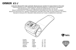
Characteristics briefly
The TKP / TKC Controller series includes all
necessary functions used in refrigeration and
freezing applications:
• refrigeration controller for all applications
of cold stores, freezers, shelfs, chest
freezers...
• for use as single controller or in a network
• 6 inputs for temperature sensors
• 6 relay outputs
• 4 digital inputs (mains voltage)
• 1 analog output
• each input and output can be assigned
to a certain function.
• available in three different housings
Some Standard Functions
•
•
•
•
•
•
•
•
•
•
•
•
•
Intelligent defrost control, able to learn (x140 only)
LC-Display, dot-matrix, plain text
Operation by 4 keys on the front
Temperature control for up to 4 circuits
2nd setpoint (day / night shift)
Alarm thermostat
with monitoring of each evaporator
Compressor Idle-Time
Fan control with delay times for start and stop
Runtime monitoring of refrigeration
Roller blind control
Frame heater control, pulsed, different for day and night
Analog output usable for actual value image or for P, PI,
PID-T1-control with service functions
Adjustable Emergency Mode
Door contact input
• Works with the 2 standard temperature sensors only:
Room sensor, evaporator sensor
• Autoadaptive Defrost Demand Recognition,
suitable both for single compressor applications
and for compound systems.
• Defrost Start:
fully automatic, 6 release times or manually
• Defrost cycle is pulsed, controlled by evap sensor
(variable intervals)
• Automatic recognition of the leading evaporator
at cold storages with several evaporators
• Emergency Mode if sensor or defrost recognition fails.
Autoreset if malfunction is repaired.
Use of Latency Heat
Please note Safety
Informations !
• Fan following (less compressor starts)
• Intelligent fan control before defrost
• Special mode if room temperature is above 2,5°C
The evaporator will be defrosted by airflow during the
refrigeration periods (less defrosts necessary).
ELEKTRONISCHE REGELUNGEN GMBH
Page 2
Contents
Page
Brief Description .......................................................... 1
Operating / Operating elements ................................. 3
Programming ............................................................... 3
Access Protection ....................................................... 4
Parameter pages
'Actual values' page ............................................... 5
Setpoints page ....................................................... 6
Defrost page .......................................................... 7
Mode page ............................................................. 8
Assignment page ................................................... 9
Functional Description
Failure messages .................................................. 11
Actual values, Information-/Status display ........... 11
temperature display, setpoints,
time informations, state informations,
temperature sensor, 'Basic display'-function
Configuration Concept .......................................... 12
Cooling ................................................................... 13
Circuits, cooling / heating,
2nd setpoint (day / night shift)
2nd setpoint level, emergency operation,
runtime monitoring,
single compressor operation
Temperature alarm ................................................ 14
Digital inputs (Optocoupler inputs) ........................ 14
Switching OFF controller / circuits
Security chain monitoring
Door contact inputs
Lighting control
External alarm
Others
Display language
Real time clock
Unit text
Analogue Output .................................................... 15
Actual value image, PID-controller
Defrost ................................................................... 16
Pulsed defrost
Defrost on demand - Standard Methods
Adaptive Defrost Method ................................. 17
Fan control ............................................................. 19
Operation modes, trailing,
start-up delay
Roller blind / Frame heater control ....................... 20
Adding controller units to extend cold storages ...... 21
Networking via E-Link ................................................. 22
E-Link, Remote operation at an SMZ,
configuration by PC, data cable wiring,
networking in a VPR-19000-System.
Sensor positions / Getting Started .............................. 23
Basic Configuration of TKP 3130/1 ............................ 24
Connection / Safety Informations ............................ 24
Connections / Wiring
Housing TKP 31x0 ................................................. 25
Housing TKP 51x0 ................................................. 25
Housing TKC 191x0 .............................................. 26
Technical Data ............................................................ 27
CE-Statement of Conformity ....................................... 27
Technical Manual Cold Storage Controllers TKP / TKC x130 - x140
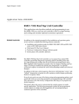
Available Types
l TKP 3130 230V, for DIN-rail
l TKP 3130/1 without display and keys,
TF 501 (Pt1000) sensors only
l TKP 3140 like 3130 but
with intelligent defrost
TKP-3000
LIST
PROG
1
2
3
1
2
3
4
ELREHA
l TKP 23130 110V, for DIN-rail
l TKP 23140 like 23130 but
with intelligent defrost
l TKC 5130
l TKC 5140
230V, panel mounting (96x96mm)
like 5130 but with intelligent defrost
1
5
LIST
2
6
3
l TKC 25130 110V, panel mounting (96x96mm)
l TKC 25140 like 25130 but with intelligent defrost
7
PROG
4
8
ELREHA
TKC-19"
l TKC 19130 230V, 19"-Al-cassette, 14 TE
l TKC 19140 like 19130 but with intelligent defrost
LIST
PROG
l TKC 29130 110V, 19"-Al-cassette, 14 TE
l TKC 29140 like 29130 but with intelligent defrost
1
2
3
1
2
3
ELREHA
4
Technical Manual Cold Storage Controllers TKP / TKC x130 - x140
Page 3
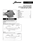
Operating / Operating Elements
The operating elements of all TKP/TKC-types are identical,
independent from their housing.
Operating Elements
up / down keys
LCD-display for
parameters and values
The units can be operated by 4 keys, all parameters will be
displayed in plain text on the backlighted LC-display.
TKP-3000
leave page
LISTE
The TKP 3130/1 will be operated from keypad and display of the
VPR Compound Control System.
PROG
ELREHA
circuit 1
circuit 2
circuit 3
cooling
circuit 1
circuit 2
circuit 3
circuit 4
defrost
alarm
enter page /
confirm values
Programming
All readable and adjustable values (parameters) of the TKx units are listed on several pages. While normal operation or if no key is pressed
for about 3 minutes, the display shows the following informations:
1. priority:
2. priority:
3. priority:
current failure (only if there is a failure at the moment)
controller states (e.g. if it is turned OFF by a digital input)
the selected 'Basic Display'
Call up and changing of parameters:
Action
LISTE (= ESC),
If no pagename is
displayed
PROG
Select desired page
TKP/TKC Test
20.02.99 11:49
PROG
actual values
20.02.99 11:49
PROG
setpoint page
20.02.99 11:49
PROG
ñ
defrost page
20.02.99 11:49
PROG
defrost mode, etc.
ò
mode page
20.02.99 11:49
PROG
date, time, etc.
assignment page
20.02.99 11:49
PROG
configuration
hist.fail page
20.02.99 11:49
PROG
last failure 1,
etc.
act.fail page
20.02.99 11:49
PROG
actual
etc.
Enter this page
ñò
Select parameter
PROG
Start programming,
parameter name flashes.
Adjust desired value.
Pressing and holding a
key effects that the value
will be incremented or
decremented automatically faster and faster.
PROG
Leave programming
mode, confirm new value
Liste (= ESC)
Back to page overview.
ñ ñ ñ ñ ñ
Eventually, the unit asks
here for an access code
('Identification', see next
page)
ñò
LISTE
ñ ñ ñ
ñò
Parameter Pages
ñ
Key
User Code
sensor 1, etc.
setpoint level X,
etc.
failure,
Page 4
Technical Manual Cold Storage Controllers TKP / TKC x130 - x140
Access Protection / Unauthorized changing of parameters
User levels
Identification
To avoid that unauthorized persons change parameters, the parameters are access protected until a correct code is entered.
3 different user levels exist:
Almost all parameters, except the temperature setpoints, are protected by a simple password.
1. Customer Level
In this level only setpoints can be changed or defrost can be
started manually, but it is impossible to change the configuration of the unit.
2. Service Level (call-up with code 2)
Here the service contractor finds parameters and information
for start-up and service.
3. Configuration Level (call-up with code 3)
Here you can change all parameters, even the fundamental
functions to assign inputs and outputs.
In the single levels only the accessable parameters will be displayed
(marked by 'Level 1,2,3' on the parameter pages).
If you have to change a parameter and you have pressed the
"PROG"-key, this display appears:
Identification
Enter :> 0 <
The controller expects now the input of a code-no.
This code-no. (Code 1) is related from the actual time of the day as
the sum of the
hour (0 to 23) plus 10
Example:
At 9:35 a.m. the code is 9 + 10 = 19.
At 21:35 (9:35 p.m.) the code would be 21 + 10 = 31.
Using the Access Protection
The parameter „operator layer“ on Mode Page is factory set to „no“.
Thus you will see all parameters, the same as if the 'ConfigurationLevel' would be active.
After start-up, you protect the controller unit effectively by changing
parameter „operator layer“ (mode page) to „yes“. If you don’t touch
any key for at least 3 minutes or if you switch off power for a moment,
protection will be activated. Thus only the parameters of the Customer
Level can be displayed.
All other parameters are hidden now and can be accessed only by
knowing the code.
To change from Customer Level to Service- or Configuration Level
do as follows:
•
•
•
Select 'basic Display',
Press key "Prog",
Enter code for desired level.
TKP/TKC
16.06.99 14:39
operator
Enter :> 0 <
Change parameters
To change a parameter in the single user levels, the unit frequently
expects an additional 'Identification Code'. (see right column).
As long as parameter "operator layer" is not set to "no", the unit
changes to the Customer Level if no key is pressed for about 3
minutes.
Codes
Code 2: ........ Fixed Code: - 88 - (calls up Service Level)
Code 3: ........ Month + Hour + 20 (calls up Configuration Level)
Example:
(Note: Real-time clock must be set to the right time and
date before.)
You want to change a parameter at a day in june at 9:35
in the morning. Identification Code = 6 + 9 +20 = 35.
If you have pressed no key for about 3 minutes, the parameters
are locked again automatically.
Technical Manual Cold Storage Controllers TKP / TKC x130 - x140
Page 5
Parameter pages
Actual Values
Disp Level Range
only
sensor 1 xxxxxxx
1
Default val.
Your value
Display of the temperature of this sensor
range -100/+100°C,
calibr. = 0
calibration range here is +/- 10K
x
indicates the function assigned to this sensor:
Rx = control sensor x,
Wx = alarm sensor x
DO = display only sensor,
w1 = defrost demand sensor warm x
c1 = defrost demand sensor cold x
Dxy = evap sensor, circuit x / no.y
sensor 2
1
dto.
calibr. = 0
sensor 3
1
dto.
calibr. = 0
sensor 4
1
dto.
calibr. = 0
sensor 5
1
dto.
calibr. = 0
sensor 6
1
dto.
calibr. = 0
X
1
refrigeration runtime today
run time refr. 4
X
1
door open 1
X
1
door open 4
X
1
rem. door open 1
X
2
run time refr. 1
00:00
thru
00:00
total door open time today
00:00
thru
00:00
remaining time before alarm
"door open" ("---" = door closed)
thru
rem. door open 4
X
2
h:min:sec
remain alm delay
X
2
remaining time before temperature alarm
remain defr time
X
2
remaining defrost time in mm:ss
rem. defr pause 1
X
2
h:min:sec
rem. defr pause 4
X
2
remain fandelay 1
X
2
remain fandelay 4
X
2
rem compr pause1
X
2
rem compr pause4
X
2
rem strt sec ch(ain)
X
2
rem chck defrdem
X
2
min:sec
00:00:00
dem defr stored
X
2
yes, no
no
solenoid valve
X
2
enabled, off
status
X
1
off circuit X
night settings
X
1
day, night
2
h:m:s (resettable only)
thru
h:min:sec
thru
h:min:sec
thru
runtime relay 1
h:min:sec
00:00:00
thru
runtime relay 6
2
00:00:00
analog value
X
1
output is X% of the selected range
OC1 OC2 OC3 OC4
X
1
voltage at this digital inputs
relay status
X
1
state of relays 1-6, 1=ON, 0=OFF
Parameters marked with "Disp. only" are for Information only and cannot
be adjusted.
The numbers in column "Level" show the user level, where this parameters
are displayed.
Page 6
Setpoint page
Technical Manual Cold Storage Controllers TKP / TKC x130 - x140
Le Range
vel
Defaultvalue
Examples
Your Value
walk-in fr. chest fr.
walk-in (+4°)
refrig. shelf
setpoint layer
1
1, 2
1
1
1
1
1
setpoint Ch 1
setpoint Ch 2
1
1
-50/+50°C
-50/+50°C
-20°C
-20°C
-20°C
-26°C
+4°C
+1°C
---
---
---
+3°C
setpoint Ch 3
setpoint Ch 4
1
1
-50/+50°C
-50/+50°C
-20°C
-20°C
---
---
---
---
---
---
---
---
2nd setp Ch 1
2nd setp Ch 2
1
1
-50/+50°C
-50/+50°C
-20°C
-20°C
---
- 24°C
---
+3°C
---
---
---
+5°C
2nd setp Ch 3
2nd setp Ch 4
1
1
-50/+50°C
-50/+50°C
-20°C
-20°C
---
---
---
---
---
---
---
---
alt setp Ch 1
alt setp Ch 2
1
1
-50/+50°C
-50/+50°C
-20°C
-20°C
---
---
---
---
---
---
---
---
alt setp Ch 3
alt setp Ch 4
1
1
-50/+50°C
-50/+50°C
-20°C
-20°C
---
---
---
---
---
---
---
---
alt 2nd setp Ch 1
alt 2nd setp Ch 2
1
1
-50/+50°C
-50/+50°C
-20°C
-20°C
---
---
---
---
---
---
---
---
alt 2nd setp Ch 3
alt 2nd setp Ch 4
1
1
-50/+50°C
-50/+50°C
-20°C
-20°C
---
---
---
---
---
---
---
---
warning offset
2
0...50K
(relative to the active setpoint)
7K
---
15K
5K
50K
alt warn offset
2
0...50K
(relative to the active setpoint)
7K
---
---
---
---
warn low limit
2
-50/+50°C
(absolute value)
- 22°C
off
off
2°C
-35°C
alt warn low lim
2
-50/+50°C (Absolutwert)
(absolute value)
- 22°C
off
off
2°C
-35°C
hysteresis
PID propor band
2
2
0,1...20K
0,1...30K
2K
4K
2K
4K
2K
2K
---
---
---
---
PID integr time
PID attack time
2
2
off, 00:00 thru 10:00 min:sec
off, 00:00 thru 00:10 min:sec
10 sec.
off
---
---
---
---
---
---
---
---
PID delay
opto->analog val.
2
2
off, 0,1 thru 10 sec.
0,0...100,0 %,
off
0%
---
---
---
---
---
---
---
---
2
digital (OC-) input
0:00:00 thru 0:30:00 (h:min:sec), 0:05:00
0:03:00
---
0:03:00
---
fan off delay
2
freeze-on time
00:00 thru 30:00 min:sec
00:00
0:02:00
---
0:02:00
---
warning delay
cooling limit
2
2
0:00:00 thru 2:00:00 (h:min:sec)
0:00 thru 23:59 (h:min), off
0:45:00
off
1:00:00
1:00:00
1:00:00
1:00:00
---
---
---
---
door time limit
refrDlyAftMnsOff
2 0:00 thru 23:59 (h:min), off
2 0...30 min
off
0 min
---
---
---
---
compr. pause
OC inp alm delay
2
2
00:00 thru 30:00 hh:mm
00:00 thru 02:00 hh:mm
00:00
00:05
---
---
---
---
---
---
---
---
door alm delay
sec chain delay
2
2
00:01 thru 04:00 hh:mm
00:00 thru 01:00 min:sec
00:05
01:00
---
---
---
---
---
---
---
---
voltage / current from analog
output with activated
fan start delay
- Parameters marked with
"Disp. only" are for Information only and cannot be
adjusted.
- The current active setpoints /
alarm offsets / alarm limits are
marked by additional arrows in
the display.
- The numbers in column
"Level" show the user level,
where this parameters are
displayed.
Example:
2nd setp Ch 1
-> -20.0 C
° <-
Technical Manual Cold Storage Controllers TKP / TKC x130 - x140
Defrost page
Disp Le- Range
Dim.
only vel
Page 7
Default-
Examples
value
walk-in fr. chest fr. walk-in (+4°)
refrig. shelf
Your value
defrost type (fan dur.defr.)
2
on, off
off
off
---
on
---
defrost mode
2
extern(al only),
extern
ext/int
ext/int
ext/int
ext/int
extern+intern
+intern
5:00
5:00
5:00
difference meth.,
dem def by opti,
adaptive *
defrost time 1
1
00:00 - 23:59, off
hh:min 5:00
6:00
defrost time 2
1
00:00 - 23:59, off
hh:min off
21:00
20:00
11:00
13:00
defrost time 3
1
00:00 - 23:59, off
hh:min off
off
off
17:00
21:00
defrost time 4
1
00:00 - 23:59, off
hh:min off
off
off
23:00
---
defrost time 5
1
00:00 - 23:59, off
hh:min off
off
off
---
---
defrost time 6
1
00:00 - 23:59, off
hh:min off
off
off
---
---
defr temp limit 1
2
(control circuit 1)
°C
14°C
8°C
8°C
8°C
8°C
°C
14°C
---
---
---
8°C
°C
14°C
---
---
---
8°C
°C
14°C
---
---
---
---
0,0°C....50,0°C
defr temp limit 2
2
(control circuit 2)
0,0°C....50,0°C
defr temp limit 3
2
(control circuit 3)
0,0°C....50,0°C
defr temp limit 4
2
(control circuit 4)
0,0°C....50,0°C
last defr cycle 1
X
2
(circuit 1) min:sec
mm:ss 00:00
---
---
---
---
last defr cycle 2
X
2
(circuit 2) min:sec
mm:ss 00:00
---
---
---
---
last defr cycle 3
X
2
(circuit 3) min:sec
mm:ss 00:00
---
---
---
---
last defr cycle 4
X
2
(circuit 4) min:sec
mm:ss 00:00
n/o defr ignored
X
2
0, 1, 2, 3, 4, 5, 6
demand defr diff
2
0,0...20,0K
dem defr period
2
00:00...10:00 mm:ss
pulsedef. limit
2
-5,0...+50,0°C
defr alarm delay
2
00:00 thru 60:00
mm:ss 30:00
pause ahead defr
2
0...15 min
min
pause aft. defr
2
00:00 thru 30:00
mm:ss 00:00
n/o.def.evnt > alm
2
Number of defrost
---
---
---
---
0
---
---
---
---
5K
---
---
---
---
mm:ss 02:00
---
---
---
---
°C
+3°C
50°C
+3°C
50°C
30:00
30:00
30:00
30:00
1:00
00:00
00:00
00:00
off
off
off
off
45:00
45:00
30:00
45:00
---
---
---
---
K
50,0°C
0
cycles without alarm,
off, 1-15
3
mm:ss 45:00
max defrost time
2
00:00 thru 4:00:00
manual defrost
1
start, finish
* defrost forerun
2
00:00 thru 00:15
* time (up) to defr
* max time to defr
X
2
hh:min:sec
2
02:00 thru 48:00
hh:mm 00:03
hh:mm 24:00
* in TKP/TKC x140 only.
- Parameters marked with "Disp. only" are for Information only and cannot be adjusted.
- The numbers in column "Level" show the user level, where this parameters are displayed.
Page 8
Mode page
Technical Manual Cold Storage Controllers TKP / TKC x130 - x140
Disp Le- Range
Dim. Default-
only vel
value
Examples
walk-in fr. chest fr. walk-in (+4°)
refrig.shelf
compound
2
1, 2, none
1
2 (TK)
2 (TK)
---
---
fan operation
2
interval, permanent
interval
interval
---
interval
---
cooling mode
2
refrigeration,
refrigeration
freezing
freezing
refrigeration
refrigeration
freezing
emergency operat.
2
0...100%
0%
60%
80%
50%
50%
frame period
2
10:00...60:00 mm:ss
15:00 mm:ss
---
30:00
---
---
frame pulse day
2
0...100%
100%
---
80%
---
---
frame pulse nigt
2
0...100%
100%
---
40%
---
---
alm temp. low
2
yes, no
yes
no
no
yes
yes
night setp ON
2
0:00 thru 23:59, off
off
---
---
---
20:00
night setp OFF
2
0:00 thru 23:59, off
off
---
---
---
6:00
runtime mess at
2
0...23 h
6h
---
---
---
---
corr sensor 1
2
calibration offset,
K
---
---
---
---
K
---
---
---
---
K
---
---
---
---
K
---
---
---
---
K
---
---
---
---
K
---
---
---
---
Pt1000
!
!
!
!
adjustable +/-10
(actual value also adjustable)
corr sensor 2
2
calibration offset,
adjustable +/-10
(actual value also adjustable)
corr sensor 3
2
calibration offset,
adjustable +/-10
(actual value also adjustable)
corr sensor 4
2
calibration offset,
adjustable +/-10
(actual value also adjustable)
corr sensor 5
2
calibration offset,
adjustable +/-10
(Istwert dto. einstellbar)
corr sensor 6
2
calibration offset,
adjustable +/-10
(actual value also adjustable)
sensor (type)
3
!! 3130/1=Pt1000 only
TF 201 (PTC),
TF 501 (Pt 1000)
unit text
3
unit name as desired
TKP
---
---
---
---
operator layer
3
yes, no
no
---
---
---
---
1
version no. of this
---
---
---
---
EU from
EU ab
EU from ‘96
EU from ‘96
EU from 1996
‘96
‘96
program version
X
program
summer / winter
3
no, EU up to 1995,
EU from 1996
actual time
2
h:min:sec
---
---
---
---
actual date
2
day:month:year
---
---
---
---
Sprache / language
2
deutsch, english,
---
---
---
---
9600
9600
9600
9600
---
---
---
---
francais,
Nederlands
baudrate
3
1200, 2400, 4800,
9600
9600
adress in netwk
3
0 - 78
- Parameters marked with "Disp. only" are for Information only and cannot be adjusted.
- The numbers in column "Level" show the user level, where this parameters are displayed.
Your value
Technical Manual Cold Storage Controllers TKP / TKC x130 - x140
Page 9
Assignment page
Level Range
Default value
function relay 1
3
alarm
--, on, refrig. 1, refrig.2, refrig.3, refrig.4
defrost11, defrost12, defrost13, defrost14,
defr. 11 thru 44 means:
defrost21, defrost22, defrost23, defrost24,
defrost yz
defrost31, defrost32, defrost33, defrost34,
y=circuit, z=evaporator
defrost41, defrost42, defrost43, defrost44,
Example:
fan 1, fan 2, fan 3, fan 4, unit on
Examples
walk-in fr. chest fr.
walk-in (+4°)
refrig. shelf
alarm
alarm
alarm
alarm
refrig. 1
refrig. 1
defr.11 = defrost relay
control circuit 1,
alarm, frame heater, roller blind,
evaporator 1
light, heater 1
function relay 2
3
dto.
refrigeration 1
refrig. 1
refrig. 1
function relay 3
3
dto.
refrigeration 2
fan 1
frame heater fan 1
refrig. 2
function relay 4
3
dto.
frame heater
defr. 1/3
defr. 1/3
defr. 1/3
roller blind
function relay 5
3
dto.
defrost 21
defr. 1/2
defr. 1/2
defr. 1/2
off
function relay 6
3
dto.
defrost 11
defr. 1/1
defr. 1/1
defr. 1/1
refrig. 3
function Opto. 1
3
---, manual defrost, night settings,
man. defrost
m. defrost
m. defrost
m. defrost
m. defrost
night settings
night sett.
night sett.
night sett.
night sett.
(digital input OC 1)
unit OFF actHigh, security chain,
setpoint layer, door contact 1...4
alarm input 1,alarm input 2
alarm input 3, alarm input 4,
circuit OFF 1 - - - thru
circuit OFF 1 2 3 4, analog value,
refLock actLow, refLock actHigh,
refForce actLow, refForce actHigh,
unit OFF actLow, circ.OFF.low 1 - - thru circ.OFF.low 1 2 3 4
function Opto. 2
3
dto.
function Opto. 3
3
dto.
controller OFF
contr. OFF contr. OFF
contr. OFF
contr. OFF
function Opto. 4
3
dto.
---
setp. layer setp. layer
setp. layer
setp. layer
funct. sensor 1a
3
- - - (sensor is switched OFF),
control sens. 1
contr.sens1 alm sens 1
contr.sens.1
contr.sens. 1
control sensor 1 ... control sensor 4,
defr sensor x/x =
defrost sensor circuit x / no. x,
demdefr sens co1,
demdefr sens wa1,
alarm sensor 1 thru alarm sensor 4,
disp only sens
Page 10
Technical Manual Cold Storage Controllers TKP / TKC x130 - x140
Assignment page
Level Range
Default value
walk-in fr. chest fr.
walk-in (+4°)
refrig. shelf
funct. sensor 1b
3
dto.
alarm sensor 1
alm sens 1 - - -
alm sens 1
alm sens 1
funct. sensor 1c
3
dto.
---
---
---
---
---
funct. sensor 2a
3
dto.
defr. sens. 1/1
defr.s 1/1
defr.s 1/1
defr.s 1/1
funct. sensor 2b
3
dto.
---
---
contr.sens 1 - - -
alm sens. 1
funct. sensor 2c
3
dto.
---
---
---
---
---
funct. sensor 3a
3
dto.
control sens. 2
alm sens. 1 alm sens. 1
alm sens. 1
defr.sens1/2
funct. sensor 3b
3
dto.
alarm sensor 2
---
---
---
alm sens. 2
funct. sensor 3c
3
dto.
---
---
---
---
funct. sensor 4a
3
dto.
defr. sens. 2/1
defr.s 1/2
defr.sens 1/2 defr.sens 1/2
contr. sens 2
funct. sensor 4b
3
dto.
---
---
contr. sens 1 - - -
alm sens. 2
funct. sensor 4c
3
dto.
---
---
---
---
---
funct. sensor 5a
3
dto.
disp only sens
alm sens. 1 alm sens. 1
alm sens. 1
defr.sens1/3
funct. sensor 5b
3
dto.
---
---
---
---
alm sens. 3
funct. sensor 5c
3
dto.
---
---
---
---
funct. sensor 6a
3
dto.
disp only sens
defr.s 1/3
defr.sens 1/3 defr.sens 1/3
contr. sens 3
funct. sensor 6b
3
dto.
---
---
---
---
alm sens. 3
funct. sensor 6c
3
dto.
---
---
---
---
---
analog function
3
0V, 4mA, 10V / 20 mA
act.img 0-10V
---
---
---
---
Examples
act.img 0-10V, act.img 4-20mA,
PID-T1 0-10V, PID-T1 4-20mA
O 1/2 - O 3/4
2
PID-T1 10-0V, PID-T1 20-4mA
state of the digital (OC)-inputs 1-4
display only
R 1/3 - R4/6
2
state of the relays 1-6
display only
defr.sens1/1
---
---
Technical Manual Cold Storage Controllers TKP / TKC x130 - x140
Display of actual values and states
All actual values are shown on the 'actual values' page.
Display of the temperatures
'sensor1' to 'sensor 6' display
1. function
their actual value in the range
2. function
3. function
of -50 ... +100°C. On the same
time, the display shows the
sensor 1 R1A1-functions which are assigned
-24.5°C
to the sensor.
Sensor corrections can be
made by editing each individual sensor reading. The resulting
correction factors are listed on the mode page (corr sensor 1-6).
Setpoints:
The active day or night setpoints are indicated on the
display by „->“ and „<-“.
Status Displays
Optocoupler 1.......Optocoupler 4
OC1 OC2 OC3 OC4
0V 230V
1 = relay activated
0 = relay de-activated
0V = no voltage
Temperature Sensors
There are two types of temperature sensors which can be used:
- TF 201, PTC sensor (2000 ohms@25°C), !! not 3130/1 !!
- TF 501, PT1000 sensor (1000 ohms@0°C)
The type must be preset by 'sensor' (mode page).
'Permanent Parameter' - Function (Basic Display)
After switching on the controller, the display will indicate the 'permanent parameter' after some seconds (or in case of a failure it will
display the actual failure):
TKP/TKC
18.01.00
All failures will be memorized with date and time of their appearance.
To display this messages, 2 pages exist:
Actual failures page
This page contains all current failures in a short form. To make more
than one current failure visible, use the 'up/down'-keys. If a sensor
is short or broken, this message also appear on the actual value
display.
Historic failures
setpoint CH 1
-> -22.5°C <-
Information about delay times
On the actual values page you will find all remaining delay times, so
it is easy to verify the points in time when specific functions must
start.
relay status
010111
Failure Messages / Failure Memory / Failure Codes
On this page you will always find the last 15 failures memorized with
date and time of their appearance.
active setpoint is marked
Relay 1.......................Relay 6
Page 11
Failure Codes
----
no failure
Init
first initialisation of the controller
or data lost
Hard
hardware failure
MOFF
mains supply cut off
MON
mains supply switched on
SiCh
security chain open
SBr X
sensor X broken
SSH X
sensor X short
If a sensor is short or broken, a time delay of 5 seconds takes effect before
an alarm will be activated.
HT X
one of the alarm sensors of circuit X
high temperature
LT X
one of the alarm sensors of circuit X
low temperature
MRC X
cooling of circuit X has exceeded maximum
runtime. This message is only active up to
'runtime mess at' (mode page).
OPC X
alarm on digital (OC) input X, assigned as
alarm input
DOR X
door contact of circuit X open too long. This
message is only active up to 'runtime
mess at' (mode page).
DEF X
number of defrost cycles without
termination by temperature exceeded in
circuit X, maybe too many ice or heater
malfunction.
ASSI
error on assignment page,
e.g. function programmed too often
COon
controller unit switched ON by interface
or by digital input
COof
controller unit switched OFF by interface
or by digital input
OFF X
circuit X switched off by interface or by
digital input
09:24
This will also be showed if you have selected some parameters and
you don’t touch a button for more than 3 minutes.
If you think that it is suggestive to show any sensor value as
permanent parameter, do the following:
Change permanent parameter
- Select parameter you want to have as 'permanent parameter'
- Press
ñ and ò simultaneaously.
The display becomes dark for a moment, after that the selected
parameter will be shown as basic display.
Page 12
Technical Manual Cold Storage Controllers TKP / TKC x130 - x140
Configuration Concept
As a refrigeration contractor or a planning engineer you often have the
problem to get the right cold storage controller that fits perfectly to your
application. By using the TKP3130 this problem is no longer the issue, since
this controller is designed to be universal. Its ‘free c o n f i g u r a b l e’ concept
enables you to use it for almost all refrigeration applications.
The ‘free configurable’ concept means that all controller inputs and outputs
(6 relays, 6 sensors, 4 digital (OC)-inputs, 1 analog output) can be configured
to work with any integrated control functions or control circuits.
Assignment
The function of each input and output can be preset on the 'assignment page'.
The assignment can be done by the keys or via interface.
Example of a configuration for a freezer with 3 evaporators:
Sensors
Each sensor can fulfill each function, even up to 3 functions at the same time
(function sensor X a, function sensor X b, function sensor X c, X = sensor no.).
e.g. cold store: function sensor 1 is:
1a: control sensor and
1b: alarm sensor
or refrigerated shelf:
function sensor 1 is:
1a: control sensor,
1b: defrost sensor and
1c: alarm sensor.
Digital Inputs (OptoCoupler Inputs)
Each digital input can be assigned to one of the possible functions.
Relay Outputs
Each relay can be used to control one of the possible functions. The same
function can even be allocated to multiple relays.
Parameters
Parameters of functions which are not assigned will not appear in the
parameter pages to improve survey.
1: control sensor 1....
2: alarm sensor 1.....
3..............................
sensor 1
1: defrost sensor 11
2: .............................
3.............................
sensor 2
1: alarm sensor 1......
2: ...............................
3................................
sensor 3
1: defrost sensor 12
2: ...............................
3...............................
sensor 4
1: alarm sensor 1........
2: .................................
3................................
sensor 5
1: defrost sensor 13...
2: ................................
3...............................
sensor 6
manual defrost
OC 1
night settings
OC 2
Regler AUS
OC 3
Sollwertebene 2
OC 4
relay 1
alarm
relay 2
refrig. 1
relay 3
fan
relay 4
defrost 1/3
relay 5
defrost 1/2
relay 6
defrost 1/1
analog
actual value image
TKP/TKC
allocation of
inputs-/outputs
Configuration of the controller
Hereby we use the example from above: freezer with 3 evaporators
action
key
select assignment page
"ñò"
enter assignment page
"PROG"
select desired output
"PROG"
enter code depending on time
"ñò"
confirm
"PROG"
select function for this output
"ñò"
confirm
"PROG"
select new input/output
"ò"
prepare for programming
"PROG"
select function for this output
"ñò"
confirm
"PROG"
select new input/output
"ò"
prepare for programming
"PROG"
select function for this output
"ñò"
confirm
"PROG"
display
remarks
assignment page
05.06.01 14:10
function relay 1
--identification
Enter :> 0 <
function relay 1
--function relay 1
alarm
function relay 1
alarm
function relay 2
--function relay 2
--function relay 2
refrig. 1
function relay 2
refrig. 1
function relay 3
--function relay 3
--function relay 3
fan 1
function relay 3
fan 1
at the beginning of programming only, or after
no key is pressed for about 3 minutes
flashing
flashing
flashing stops, relay already working
flashing
flashing
flashing stops, relay already working
flashing
flashing
flashing stops, relay already working
Repeat this steps until all inputs and outputs are assigned to the desired functions.
Technical Manual Cold Storage Controllers TKP / TKC x130 - x140
Page 13
Heating function
Temperature sensors
Two control sensors can be assigned to each
circuit. If one of them gets warmer than setpoint
plus hysteresis then cooling starts. Cooling doesn’t
stop until both have achieved the setpoint.
Cooling
Cooling is controlled by switching the output relay.
In case of power loss or controller defects the
contacts must switch in a position which is safe for
the application. For this reason we are using the
N/O-contact for refrigeration applications (fail-safe:
open contacts). For freezing applications we use
the N/C-contacts (fail-safe: closed contacts).
refrig. relay
fan relay
The cut-in will be:
• for cooling at setpoint + hysteresis and
• for heating at setpoint - hysteresis.
refrig.ON
off
cold
warm
heating ON
hysteresis
cooling
mode=
refrigeration
For one relay it is possible to assign the function of
heating circuit 1.
The setpoint is the cut-off of heating and cooling at
the same time.
hysteresis
Control circuits
This controller is able to control up to 4 independent cooling circuits, each with an own setpoint.
Second setpoint (night operation)
setpoint
Cooling
L
For each of the 4 circuits a second setpoint is
available (2nd setp Ch X). This can be used for
night operation or other energy savings. The
toggling between these setpoints can be made by
the internal clock or by digital input. The setpoint
which is in use at the moment is marked by two
arrows like: „—> -20,0°C <—“. In the actual values
page you see also if day or night setpoint is in use.
Internal toggling
The parameters „night setpt ON“ (mode page)
and „night setpt OFF“ determine the period
when the 2nd setpoint will be active. If the
function 'night settings' is assigned to one of the
digital inputs, it must be connected to mains
phase. If the internal timer is not used, set 'night
setp. ON' and 'night setp. OFF' times to „OFF“.
External toggling
If the 'night settings' input is open, the 2nd
setpoint is activated all time and the internal
timer is disabled. With this digital input to mains
phase, the normal (1st) setpoint is activated and
the internal timer is enabled.
M
Runtime Monitoring
refrig.relay
fan relay
cooling
mode=
freezing
L
M
This can be set by parameter "cooling mode"
(mode page). The point of cut-off is always the
valid setpoint.
The selection of this parameter also affects to the
switching characteristic of the fan relay.
cooling = relay ON
refrigeration
warm
hysteresis
setpoint
relay OFF
cold
The controller monitors the total running hours per
day of the cooling outputs. This values are displayed
under parameters „run time refr. x“ for each circuit.
One day counts from the time of the parameter
„runtime mess at“ (mode page) until the same time
of the next day.
Example:
"runtime mess at" set to 11:00.
Monitoring time range is from 11:00 o'clock day
1up to 10:59 o'clock day 2.
A parameter „cooling limit“ can be set to a
reasonable value (hours per day) which, when
exceeded on three days in a sequence, will cause
an alarm at the hour programmed by „runtime
mess at“. Then the alarm relay will be de-activated
and the alarm LED goes on.
This alarm will be cancelled automatically 1
hour later.
warm
hysteresis
setpoint
freezing=
relay OFF
freezing
The controller offers two sets (layers) of setpoints,
where the first layer of setpoint is used during
normal operation and the alternative layer of
setpoints with other temperatures is used e.g. for
other products which will be stored only sometimes.
For each layer there are parameters for the
setpoints, the night setpoints, warning offsets and
low temperature warning. The names of the second set parameters begin with 'alt....'.
Toggling between the setpoint layers
1. internal:
2. external:
Emergency Operation of temperature
control
30 minutes
Operation with a single compressor
emergency
operation
in %
The refrigeration relay can be disabled via interface
(see chapter "networking via E-Link").
Refrigeration delay after power up
The start of refrigeration after power-up resp.
mains loss can be delayed by parameter
"refrDlyAftMnsOff" (Setpoint Page). In plants with
many cold storages this function prevents that
after power-up all solenoid valves open at the
same time, even though not enough machine
power is present yet.
with parameter „setpoint layer“
assign function „setpoint layer“ to
a digital input. If connected to
mains phase, the 2nd layer is in
use.
If all room sensors of a circuit fail, the controller will
turn to an emergency operation mode for this
circuit. The refrigeration relay switches on in certain
intervals, preset by „emergency operat“ (mode
page). The total period is 30 minutes. E.g.: selecting
emergency operation to 40% means 12 minutes
on, 18 minutes off. As soon, as the sensor works
correctly, emergency operation is finished and
normal temperature control continues.
relay ON
cold
Second Set of Setpoints
If a single compressor is controlled by a refrigeration
relay, it is suggestive to have an idle time to
prevent the machine from damages caused by
short cycle operation. The compressor can restart
only after the timer "compr. pause" (setpoint page)
is run down. The remaining time up to the
compressors restart can be read at "rem.compr
pause X" (actual page).
ON
OFF
cooling OFF
cooling ON
Page 14
Technical Manual Cold Storage Controllers TKP / TKC x130 - x140
Temperature Alarm
Any over- or undertemperature condition results in
a temperature alarm which causes the normally
energized alarm relay to de-energize. Hereby the
N/O-contacts open and the N/C-contacts close.
To avoid an alarm for short irregular conditions
there is a delay time („warning delay“, setpoint
page). The alarm condition is indicated by a LED
at the front of the controller. The alarm is cancelled
automatically if the temperature comes back to
normal. During defrost periods, temperature alarm
will be suppressed. "remain alm delay" shows the
remaining time up to an alarm occurs.
active
passive
phase
Overtemperature Alarm
It is possible to select max. 4 alarm sensors for a
circuit (e.g. 4x "alarm sensor 1"). If the temperature
at any of the alarm sensors gets higher than the
effective setpoint plus the „warning offset“ setting,
an alarm will be initiated after the delay time.
Undertemperature Alarm
If the temperature at any alarm sensor gets lower
than the „warn low limit“ setting, an alarm will come
on with the delay explained above. This setting is
an absolute value and does not refer to the control
setpoint. Undertemperature alarm can be disabled
by "alm temp low" (mode page).
Supplementary warning delay during defrost
After a defrost cycle the temperature might take
longer to stabilize and the normal warning delay
turns out to be too short. For this reason the
„defrost alarm delay“ (defrost page) setting adds
on to the normal warning delay after defrost.
Digital inputs (Optocoupler Inputs)
Switching OFF controller / Cooling Circuits
Sometimes it is necessary to switch off cold
storages completely including the controller, but if
this controller works in a network, the bus-master
detects a malfunction and generates an alarm.
Controller Off
If a digital input is assigned to the function „Unit
OFF actHigh“ and is connected to phase, all
control functions are disabled. The display
continues working, but no alarm will be activated.
This is memorized in the list of the 'historical
failures'. „Unit OFF actLow“ disables the functions
with 0V at the digital input.
Circuit Off
Each digital input can be configured to switch off
one ore more cooling circuits ("circuit OFF X").
When connected to phase, all regulation and
control functions and temperature alarms of the
concerned circuits are disabled. Nevertheless the
others are still working. This is memorized in the
list of the 'historical failures'.
Relay function 'unit on'
The function 'unit on', assigned to an output relay,
has the effect that this relay keeps switched on
during normal operation and keeps switched off
while the controller unit is disabled by digital input
or by interface. So this relay can be used to switch
a function which should be active while the controller
unit does not work.
In the mode page you have the possibility to define
a specific text (max. 16 characters) for the controller,
e.g. „apple-store“. This name will be indicated on
the screen of the compound controller VPR 19000
or on a PC with the software COOLVision.
Change text:
• select parameter „unit text“ (mode page)
• push „PROG“, the first character position flashes
(eventually, you must enter the access code
before)
• change character by the up/down-keys.
• press „PROG“ to confirm
• the next character flashes
• change this character by the up/down-keys.
....and so on
• press „PROG“ to confirm the last character.
Changing the text can also be made by the software
'COOLVision'.
Light
One of the relays can execute the function „light“,
suitable to control lightings. In this case, the relay
switches together with the night settings „night
setp. ON“ and „night setp. OFF“ (mode page).
During „day“ the relay is activated.
External Alarm
The digital inputs can execute the job „alarm input
x“. While normal operation, the input is connected
to mains phase. When the voltage drops down, a
delay time starts „OC inp alm delay“ (setpoint
page). After this timer is run down, a failure message
will be generated.
Forced Refrigeration and Defrost Lock
See chapter 'Adding controller units'.
Security Chain Monitoring
When using the controller for single compressor
applications, one of the digital inputs can be used
for monitoring the security devices ("security chain")
of the compressor. Normally the digital input is
connected to phase. But if the input is open, the
controller waits for the timer „sec chain delay“
(setpoint page) then cooling and fan are switched
off, a running defrost period is terminated and a
new defrost start is impossible. The alarm relay will
be activated. Parameter "rem strt sec ch" shows
the remaining time up to a controller unit response.
Door Contact
Unit Text
Door Open monitoring
Each time when door is open, the controller adds
this time to the total opening time of that day „door
open x“ (actual page). If the total opening time
exceeds the time set by „door time limit“ (setpoint
page) then an alarm will be generated. The failure
message will be forwarded at the point in time
determined by „runtime mess at“ (mode page) and
is cancelled automatically 1 hour later. "rem door
open 1" thru "rem door open 4" show the remaining
time up to the alarm message.
Each control circuit can get a a door contact input.
If the door contact input is connected to phase, the
fan of the circuit stops immediately. If the door is
open > 3 minutes, cooling will stop too. Parameter
"status" shows the circuit which is switched off. If
the door is open > 5 minutes, the failure message
"door X" will be generated.
Cooling and fan will restart:
- when door is closed or
- when temperature exceeds the warning limits or
- when door opening exceeds the time set by „door
alm delay“ (setpoint page). At the same time the
alarm relay will be activated.
Exception:
If no alarm sensor is assigned or if
the temperature is above the alarm
limit „ warning offset “, then cooling
continues without interruption.
The cooling keeps switched ON and the fan
starts again, so the door opening is ignored.
Display Language
The language used on display can be changed by
"Sprache/Language" (mode page) to german,
english, french or dutch.
Real Time Clock
The built-in real time clock is battery buffered,
which works for (typ.) 3 years without mains voltage.
Date and Time can be set on the 'mode page'.
An automatic summer / winter switching (parameter
„summer/ winter“) considers the current EU-rules
from 1996 (EU 96), but it can also switched off.
Technical Manual Cold Storage Controllers TKP / TKC x130 - x140
Page 15
Analog Output
Control Characteristic
setpointdeviation
The TKP / TKC contains an analog output which can be used for
regulation or to provide a remote display with an actual value image.
The signal is available as a DC-Voltage or a DC-Current-Signal.
Parameter „analog value“ (actual page) shows the current output
signal as a %-part of the selected range, "analog function" (assignment
page) determines the behaviour of the output:
Test functions
t
Transmission of actual values to remote displays or similar
act.img 0-10V =The outputs provide an image of the value of
refrig.sensor 1.
voltage:
-50°C = 0V, +100°C = 10V
current:
-50°C = 0mA, +100°C = 20mA
act.img 4-20mA = The outputs provide an image of the value of
refrig.sensor 1.
voltage:
-50°C = 2V, +100°C = 10V
current:
-50°C = 4mA, +100°C = 20mA
max.
I-part
output
= voltage = 0V, current = 0 mA fixed
= voltage = 2V, current = 4 mA fixed
= voltage = 10V, current = 20mA fixed
proportional band
0V
4mA
10V/20mA
P-part
PID
integral time
5V resp. 12mA
PI-control,
D and T1-parts
de-activated
min.
t
t
max.
I-part
output
proportional band
PID-T1 0-10V = This PID-controller with 0-10V DC-signal is
assigned to cooling circuit 1. The output signal
represents an addition of the components P, I, D
and T1.
PID-T1 4-20mA = This PID-controller with 4/20mA-signal is
assigned to cooling circuit 1. The output signal
represents an addition of the components P, I, D
and T1.
PID-T1 10-0V = PID-controller like above, but with inverted voltage
output (rising temperature = falling voltage).
PID-T1 20-4mA = PID-controller like above, but with inverted
4/20 mA-output
(rising temperature = falling current)
setpointdeviation
Control with the analog output signal (PI-control)
P-part
PID
integral time
5V resp. 12mA
PID-control,
T1-part
de-activated
min.
t
PID attack time
To adapt the controller to the process use the following parameters:
PID
PID
PID
PID
propor band" ...... situated symmetrically to 'setpoint Ch 1'
integr time" ......... integral time (I-part)
attack time" ........ derivative time (D-part)
delay" .............. actuator response time (T1-part)
setpointdeviation
"
"
"
"
How to affect the analog output manually
t
I-part
output
For certain operations it might be usefull to affect the output signal
manually. Therefore the function „analog value“ (assignment page)
can be assigned to one of the digital inputs.
Applying mains phase to the digital input the analog output will be
forced to the value (in %) that is programmed by „opto->analogout“
(setpoint page). So e.g. a connected valve drive will be set to a
specific position.
proportional band
max.
P-part
PID
integral time
5V resp. 12mA
PID-control,
with T1low-pass filter
min.
PID delay
t
Page 16
Technical Manual Cold Storage Controllers TKP / TKC x130 - x140
Defrost
The controller allows several, different defrost
methods. This methods are available for each of
the 4 possible control circuits, that means it is
possible to assign 4 defrost relays. This relay
output(s) then control an electric heater or fan for
defrosting the evaporator(s).
A defrost cycle can be initiated by different ways.
Normally the internal clock is used, but there are
also possibilities to start manual defrost or to use
advanced functions to save energy.
Each evaporator with electric heater is monitored
by a defrost sensor.
According to the application, choose if the fan
stops or turns during defrost (parameter „defrost
type“ on or off).
• „defrost mode“ (defrost page) determines how
defrost starts:
- extern
defrost starts only when the digital input (OCinput) is activated
- extern+intern
defrost start by digital input or by the internal
clock
- difference method
defrost on demand method which uses two
supplementary sensors to measure the
temperature difference across the evaporator
- dem defr by opti(mization)
defrost on demand method, defrost is started by
the clock, but the pauses between the defrost
cycles will be calculated
- adaptive
defrost control by the intelligent, adaptive function
(only TKP/TKC x140, c.f. next pages)
An electric defrost heater is run from the N/Ocontact of the defrost relay independent from the
application (refrigeration/freezing).
Cooling is disabled during defrost automatically.
"last defr cycle 1" thru "last defr cycle 4" (defrost
page) show the expired defrost time of each
circuit.
Defrost start by clock
A built-in timer allows you to set up to six (6)
different times for defrosting within 24 hours
(„defrost time 1“ to „defrost time 6“, defrost-page).
To disable these parameters, set them to „OFF“.
The defrost cycle starts only, if the temperature at
one of the evaporator sensors is below the limitation
setpoint "defr temp limit X".
If parameter „defrost mode“ on the mode page is
set to „external“, the timer function is disabled.
Please note that this function differs
with 'adaptive' defrost
Remote Defrost Initiation
To start defrost by digital input, note that mains
phase has to be applied for 2 seconds minimum
and last not longer than the shortest possible
defrost cycle.
Pause ahead defrost
The parameter 'pause ahead defr' (Defrost Page)
causes that the defrost heaters will switch on
delayed at the beginning of a defrost cycle. This
gives a chance to pumpdown the evaporators
before heating. So the defrost heaters need less
energy, because the evaporator is already warmed
up.
Defrost on demand - Standard methods
Defrost termination by temperature
Defrost will be terminated (individually for each
output) by the corresponding defrost (evaporator)
sensor. This sensors must be placed at a position
where, by experience, ice remains the longest
time. If the temperature rises at that position, the
ice in the evaporator is probably melted completely.
A defrost cycle ends as soon as all defrost sensors
have reached the defrost limitation temperatures
„defr temp limit X“ (defrost page) or the safety time
„max defr Time“ (defrost page) has been expired.
If 2 defrost sensors are assigned to one circuit,
both sensors must reach the limitation temperature
to terminate defrost.
Defrost termination by time
In case that no defrost sensors are assigned or if
they are out of order, the defrost cycle will be
terminated if „max defr Time“ (defrost page) is
achieved. Parameter „remain defr time“ (actual
page) shows the time until expiration of this timer.
Defrost termination monitoring
Normally, a defrost period should be terminated if
the temperature in the evaporator reaches the
limitation temperature. In case of bad working
conditions like sensor slack or similar, defrost is
terminated by „max defr time“. If the number of
defrost periods terminated by timer exceeds the
number programmed by parameter „n/o .def
evnt>alm“, a failure will be indicated.
In case of defrost by airflow without
evaporator sensor, this function has to be
disabled („OFF“), because here every
defrost cycle is terminated by the timer.
Cooling Delay (drain time)
With „pause aft defr“ (defrost page) you can set a
duration where the solenoid valve(s) are disabled
after defrost termination. See the remaining time
at „remain defr pause x“ (actual values page).
Manual Defrost
A manual defrost initiation via keypad is possible
at any time.
Start : Select „manual defrost“ (defrost page).
Confirm „start“
Stop: Confirm „finish“.
Optimiziation Method (for walk-ins)
With every requested defrost cycle the controller
detects the actual period of time needed for melting
the icing at the evaporator around freezing point
(between -2°C and +2°C). This time has a
dependent relationship on the number of defrosts
needed per day or, with other words, how many of
the programmed defrost cycles can be skipped.
The result of this calculation is displayed under
parameter „n/o defr ignored“ (defrost page).
Meltingtime
Defrosts
to be
skipped
<1 >1
min min
6
5
>2
min
>3
min
>4
min
> 5 > 10
min min
4
3
2
1
none
Defrost start will be initiated by the internal clock or
a digital (OC)-input.
A manually initiated defrost cycle clears the 'skip'
memory and starts a new calculation.
Defrost Demand by Differential Method
This defrost method uses two (2) additional sensors
which sense the differential temperature across
the evaporator. This differential increases with
increased icing.
At a preset amount of icing (temperature differential) which is set by parameter „demand defr diff“
(defrost page), the controller starts a measuring
cycle for a certain amount of time which is set by
parameter „dem defr period“.
sensor
cold
control
sensor
sensor
warm
M
evap sensor
Pulsed Defrost
To save energy and to avoid creating too much
moisture it’s possible to work with a pulsed
(switched in intervals) defrost function.
If the evaporator temperature is between „pulse
def limit “ (defrost page) and the limitation
temperature (the value of „pulse def limit“ must be
lower than limitation temperature), the controller
determines about the optimal heat distribution in
the evaporator depending on the gradients of the
temperature. If the evaporator temperature reaches
„pulse def limit“, the heater is not longer heating
continually but will be switched on and off by the
controller in calculated periods until the defrost
limitation temperature is reached.
As a result of this procedure
• heat energy in the evaporator dissipates better
• the defrost limit temperature can be set lower
• less of humidity in the chamber
• save of energy
To disable this function, set „pulse defr limit“ to a
very high value.
If, during this period, the differential reading keeps
its value above setting, the controller stores the
need of defrost (displayed by „dem defr stored“).
Any stored defrost demand results in initiating a
defrost cycle at the next available defrost time
(timer) or upon activating the defrost signal input.
For achieving good results with this demand defrost
method, the two additional sensors must be placed
carefully as explained in drawing.
Technical Manual Cold Storage Controllers TKP / TKC x130 - x140
Page 17
Intelligent Defrost (adaptive defrost) for walk-ins (TKP/TKC x140 only)
Using this new defrost method is very
easy:
Targets
Defrost too soon will squander energy by
using too much heat-energy and
defrosted too late will squander energy
by decreasing the power factor of the
refrigeration plant.
The main attribute of this ice detecting
system, which is developed in cooperation with the company ‘GÜNTNER
Heat Exchangers’, is to recognize safely
the rate of icing in the evaporator which
can just be admitted and to start defrost
when icing increases either immediately
or in certain allowed periods.
The controller adapts itself to a changed
situation and optimizes the control
process, which we call the autoadaptive
defrost method.
It is particularly suitable for cold storage
chambers and enables the user to
decrease the energy expenditure during
the defrost process and increases the
operational safety of the refrigeration
unit.
Defrost itself should be made completely,
using the less energy as possible.
• set parameter „defrost mode“ (defrost
page) to „adaptive“
• set parameter „max time to defr“
(defrost page) to a value which is 2 or
3 times the normal defrost interval.
Within this period decides about the
point in time to defrost independly.
• parameter „time to defr“ (defrost page)
shows the time up to the next defrost.
Process Sequence
1. If [setpoint + hysteresis > 2,5°C] the
controller uses the fan to reduce icing.
2. In the time period set by „max time to
defr“ the controller decides itself if and at
which moment a defrost cycle is
necessary. If icing is detected, the
controller prepares defrost and begins
either immediately or at the next allowed
defrost time.
3. Cooling stops, the fan goes on turning a
certain time
4. The fan stops and the heater starts
• parameters „pulse defr limit“ and „defr
temp limit“ define the range within the
heater will be pulsed.
5. If several evaporators are installed,
each one has its own defrost sensor and
heater relay, so it is individually heated.
• set parameter „defrost forerun“ to
several minutes, so the fan will be
started before defrost heater starts.
6. When the „pulse defrost limit“ is achieved,
the heater will be cut off and on in
calculated periods. The time spacing
depends on the evaporator temperature.
• set parameter „fan off delay“ (setpoint
page) to the time that the fan will
continue running after cut-off of the
cooling relay.
7. Defrost heater is cut off completely when
„def temp limit X“ is reached.
8. Cooling and fan remain still off
(drain time).
9. After the end of „pause aft defrost“ cooling
starts, but the fan remains still off.
The procedure should be suitable even
for more than one evaporator and should
not require special sensors, but use
standard sensors.
10. After end of „fan start delay“ the fan
starts and normal refrigeration goes on.
Main Features
This defrost procedure fits especially for cold stores and freezers
which are closed (like walk-ins), but it is less efficient in applications
where the limitation sensor is located in the airflow (e.g. open chest
freezers).
This procedure reduces significantly the amount of energy the
refrigeration plant needs.
Dynamic ‘room-feeding’ situations engage the
controller to adapt itself to the new situation, without
expensive adjustment by technical personnel.
Specialized sensors or additional probes are not
required.
Especially while difficult situations (like high air-humidity, in cooldown chambers, while long opening times of the door of the cold
storage room, uneven feeding of the cold storage room, etc.) the
adaptive method protects the evaporator from glaciation safely.
• delta-t across the evaporator
during refrigeration
standardcontrol sensor
• use of latency heat
• use of refrigeration breaks
• use of informations about former defrost courses
emergency operation
standardevap sensor
self monitoring
• middle value calculations and
disturbance value filtering
pulsed heating
• breakpoint duration and defrost duration
of the last defrost events
defrostheater
Page 18
Technical Manual Cold Storage Controllers TKP / TKC x130 - x140
Intelligent Defrost (adaptive defrost) for walk-ins (TKP/TKC x140 only)
Refrigeration
Special mode for roomtemperatures > 2,5°C
Emergency operation for case of bad conditions
Even during normal operation the fan stays on
after cut-off of cooling to reduce icing.
Evaporators can be de-iced already at
temperatures from 2°C by forced air. When cooling
stops, fans are turning on until ice and frost are
melted.
Thus humidity stays in the chamber which will
improve the quality of certain goods like meat or
vegetables.
In cases if the controller recognizes that it would be
incapable or to slow to control the process, or
when it gets not enough informations, e.g.:
Recognition of icing
The more ice on the fins the more increases the
difference of temperature between the roomsensor
and evaporator sensor. The controller uses the
value of these sensors, their difference, the historic
curves of these values as well as curves and
duration of the past defrostings to calculate the
necessity of defrosting.
Use of latent energy by airflow
We recommend to use „defrost forerun“ (defrost
page) to switch on the fan several minutes ahead
the defrost cycle, while cooling stops and the
heater is not yet on.
Additionally, the fan is switched on automatically
at a certain difference between the sensors. By
this, the „cooling-energy“ is brought out of the
evaporator and stored in the chamber. This helps
also to reduce the amount of heat energy necessary
to defrost.
Additonally to the compulsatory "fan off delay" (fan
is forced to continue turning after cooling reached
the setpoint and stopped), the fan will turn from a
specific temperature [setpoint+hysteresis =>
+2,5°C] until the evaporator sensor has reached a
certain value.
• At room temperatures [setpoint+hysteresis =>
+2,5°C] notify to set parameter „max time to
defr“ to a higher value, because a defrost start
is forced if this time is past.
• Further time influence
If you want to prevent that defrost starts at
certain day-times use all the „defrost time..“
parameters and set them to points in time
where defrost is allowed. If no icing is
detected, these times will be ignored.
On the other hand, once icing detected, the
controller will wait for the next „defrost time“
before starting defrost.
• External command
Assign one of the digital inputs to „manual
defrost“. By applying voltage to that input
it is possible to start defrosting at every
moment.
Defrost heating
When „pulse defrost limit“ is achieved, the heater
is cut off. The heat energy of the resistances will
dissipate slowly and melt the ice. The length of the
cut-off is calculated by the controller and as soon
as some criteria are fulfilled, it will switch on the
heater again.
The heater will be pulsed until the temperature of
the evaporator sensor reaches the value of „defrost
temp. limit“.
This procedure fits in the same way for the case of
several evaporators in the chamber.
By this way defrost period will take longer, but
will be more efficient.
charge of unusual very humid goods
freezer door was open a very long time
the evaporator is sprinkled with water
sensor broken or shortened
defrost terminated by the max. defrost time
the emergency operation starts.
To detect malfunction of the defrost control the unit
uses the increasing of "max. defrost time".
If a defrost cycle is terminated by this time, the
controller starts several defrosts with the interval
which corresponds to (¼) one quarter of the time
which is programmed by „max time to defr“.
Therefore be careful in choosing the time for
this parameter.
Several evaporators in one chamber
For certain plants it is necessary to use several
evaporators in one chamber. Even in this case one
unique roomsensor is sufficient. E.g. for a chamber
with 3 evaporators you need only 4 sensors:
Defrost start
If all six parameters „defrost time ..“ are set to Off,
the controller decides itself when it starts defrost.
•
•
•
•
•
• one controlsensor
• three defrost sensors (one for each evaporator)
Thanks to the ability of the controller
to assign its inputs and outputs
liberally it is able to control up to 4
evaporators in one chamber.
If a defrost cycle is necessary, all evaporators will
start defrost at the same time to avoid short circuit
of air, when one is heating and the fan of another
is turning.
The one with the highest rate of icing determines
the start of the defrost cycle. The TKP/TKC
controller units are capable to determine just this
evaporator and even to adapt it when conditions
change.
Thus always the evaporator with the most ice
initiates defrost start, nevertheless the quantity of
energy which is necessary to defrost will be
calculated for each evaporator separately.
To finish defrost cycle all evaporators must have
reached the defrost limitation temperature.
After the end of the disturbance the controller
works on normally.
Example
Max time to defrost is set to 24 hours. If defrost
is not terminated by the evaporator sensor, the
controller will start defrost cycle every 24 / 4 = 6
hours until a cycle will be finished by the
evaporator sensor and not by timer.
Independent from this procedure, a failure
message will be initiated.
End of defrost
When the defrost sensor has reached the defrost
limitation temperature, the heater stops and the
controller waits until "pause after defrost" has
expired, to allow the melted water to flow to the
drainage.
Then cooling starts now, but the fans still stay OFF
until the "fan start delay" has expired to allow the
evaporator to cool down and to prevent that the
fans blow warm and humid air or water drops into
the chamber.
Technical Manual Cold Storage Controllers TKP / TKC x130 - x140
Page 19
Evaporator Fan Control
For one or all of the 4 circuits it is possible to assign a relay for the
evaporator fan. The fan control depends on the following parameters:
• „cooling mode“ (mode page)
The fan is controlled from the N/O-contact in refrigeration
mode and from the N/C-contact in freezing mode.
cooling
mode=
refrigeration
refrig. relay
fan relay
refrig.relay
Fan trailing delay
The start-up time delay for the fan after defrosting is set with
parameter „fan start delay“ (setpoint page). This avoids that water
drops will be blown into the chamber. "rem fandelay 1" thru "rem
fandelay 4" (actual page) show the remaining time up to the fans in
the single circuits will be switched on.
Examples for fan operation modes
fan relay
cooling
mode=
freezing
1. fan in permanent mode
L
This mode is mainly used with refrigerated shelfs, refrigerated
display counters and chest freezers, where the fan runs even
during defrost. It is not necessary to connect the fans to a relay
of the controller, fans run directly from mains voltage.
"fan operation" is set to 'permanent', "defrost type" is set to
'on' and "pause aft. defr" is set to '0'.
L
M
M
2. fan in interval mode, defrost by fan
• „fan operation“ (mode page)
You can select either „permanent“, where the fan runs
continously and stops only during electric defrost, or
select „interval“, where the fan runs during cooling periods
only.
In use for cold storage chambers with higher temperatures.
Use a relay output for the fan. In this case you select „fan
operation“='interval' and „defrost type“='on'.
3. fan in interval mode, defrost by electric heater/hot gaz:
In use for cold storage chambers with lower temperatures
and freezers. Use a relay output for the fan. In this case you
select „fan operation“='interval' and „defrost type“='off'.
The fan runs when cooling is on. The fan is disabled during
defrost periods and comes on after defrost with a time delay
which is set by the „fan start delay“ parameter.
• „defrost type“ (defrost page)
If „on“: fan turns during defrost
If „off“: fan ist stopped during defrost.
Fan off delay
To use latent energy of the ice and evaporator block the fan can turn
up to 30 minutes after the cut-off of the valve or compressor („fan off
delay“, setpoint page).
4. fan in permanent mode and defrost by electric heater
Use a relay output for the fan. In this case you select „fan
operation“='permanent' and „defrost type“='off'. Then the fan
will run continously and stops during a defrost period only.
The fan comes on after defrost with a time delay which is set
by the „fan start delay“ parameter.
Please note that the fan relay contacts change with the application
(refrigeration/freezing).
Fan operation modes, defrost termination using electric heaters
cooling
defrost starts
defrost ends
ON
OFF
limitation temp.
evap temperature
ON
defrost
OFF
ON
interval fan
electric heater
permanent fan
electric heater
OFF
ON
OFF
interval fan
airflow defrost
ON
OFF
fan off delay
1. "pause aft. defr"
(drain time)
1
2
2. "fan start
delay"
Page 20
Technical Manual Cold Storage Controllers TKP / TKC x130 - x140
Roller Blind control
Frame Heater control
Selecting the „roller blind“ function on the assignment page activates
the relay output for opening and closing the roller blind(s)
automatically. A defrost overrides this function and opens the roller
blind(s) for the defrost period.
Internal control
• Therefore don’t use a digital input assigned with the function
„night settings“ or the digital input must be connected to mains
voltage (= day operation).
The timer parameters „night setp ON“ and „night setp OFF“
(mode page) are activating not only the secondary setpoint(s) but
have also an effect on the roller blind.
The ON setting activates the roller blind relay and runs the roller
blind in closed position via N/O-contact. The OFF setting time deactivates the relay thus opening the roller blind again.
Frame heaters are used for freezers to avoid the door freezing onto
the door frame. In addition it prevents condensing water around the
door or on top of the frames of open chest freezers.
If one of the relays is assigned to „frame heater“ this will control the
energy to the frame heater with a certain frequency and pulse-width.
For day and night operation you can choose different values to save
energy.
The corresponding parameters on the mode page are:
• „frame period“:
• „frame pulse day“
defines the duration of the cycle,
defines the percentage of heating during day
operation within each cycle.
100% = continuous heating, 0% = off
• „frame pulse night“ defines the percentage of heating during
night operation within each cycle.
100% = continuous heating, 0% = off
External control
frame period
frame
pulse
• Therefore use a digital input and assign it to the function „night
settings“. If the digital input is connected to mains voltage
(phase), the unit works in day-mode.
ON
roller blind relay
closed:
"day operation"
ext.
contact
open
close
OFF
M
L
N
This results in de-energizing the relay when „roller blind“ is
selected and running the blind(s) open via the N/C-contact.
An open input means night-mode and runs the roller blind(s) shut
via the N/O-contact.
heater switches OFF
heater switches ON
Technical Manual Cold Storage Controllers TKP / TKC x130 - x140
Page 21
Adding controller units to extend cold storages
If one controller unit has not enough ressources to control a cold storage,
you can add one or more units. The necessary communication is made
by the digital inputs.
Each of the digital inputs can be assigned to the following jobs:
Refrigeration Lock (avtive low):
The refrigeration function of the
controller unit will be stopped as long
as 0Vare connected to the control
input.
Refrigeration Lock (avtive high): The refrigeration function of the
controller unit will be stopped as long
as mains voltage is connected to the
digital input.
Forced Refrigeration (active low):
The refrigeration function of the controller unit
will be forced as long as 0Vare connected to
the digital input.
Forced Refrigeration (active high):
The refrigeration function of the controller unit
will be forced as long as mains voltage is
connected to the digital input.
Principle of adding controller units:
solenoidvalve
or
compressor
defrostheater
solenoidvalve
or
compressor
defrost
1
defrost
1
defrostheater
optional
limitationsensor
refroferationrelay
forced refrigeration
led controller unit
(slave)
external defrost
defrostrelay
forced refrigeration
refrigerationrelay
external defrost
refrigeration
lock
leading controller unit
(master)
optional
limitationsensor
controlsensor
RS-485-data connection
led controller unit
(slave)
solenoidvalve
or
compressor
refrigerationrelay
defrost
1
defrost
1
defrostheater
The leading unit engages the cooling function of the 'slave'-units via their digital input 'Forced Refrigeration'. The 'slave'-units disable the cooling
function at the 'master'-unit via its digital input 'Refrigeration Lock', as long as a defrost function works.
Page 22
Technical Manual Cold Storage Controllers TKP / TKC x130 - x140
Networking of controllers via E-LINK
E-LINK
Remote control with SMZ
This controllers can be networked together with other ELREHAcontrol devices. For this duty ELREHA has developed E-LINK, a
transmission protocol, which will be transmitted on a two-wire bussystem based on the RS-485-Standard. With E-LINK, up to 78
controllers can be assembled.
Each controller in a network has its individual adress („adress in
netwk“, mode page). This adress is necessary for selecting the right
controller while a data package is transmitted on the network bus.
If the controllers are used outside a network, the adress and the
parameter „compound“ are of no importance.
The TKP/ TKC controller series can be operated via interface when
they are connected to a communication module SMZ 3130. The
SMZ will display exactly the same as at the TKP/TKC; the keys of the
SMZ work as if they where the keys of the TKP/TKC. So you can get
alarm messages from your equipment and you can control the
device remotely .
Configuration / Service via PC
The controllers can be linked via RS 232 or RS 485 interface to a PC
where the ELREHA-software „Coolvision“ works. From there you
can change parameters, save them on the hard disk (download) and
send it to other controllers (upload).
Wiring of data lines
shielding
Attention !
Note polarity while
connecting cables !
5 cm max.
(2.0 inch)
The scheme beside shows briefly,
how dataline wiring of several
controllers must be made. The
shield has to be grounded at each
controller to the PE-contact and to
the GND contact of the RS485!
This will assure good interference
suppression, even for long datalines
between the controllers.
44 DO NDO
N
PE
44 DO NDO
N
PE
44 DO NDO
N
44 DO NDO
PE
N
PE
GND-terminals
TKP 31x0 ..... term. 44
TKC 51x0 ..... term. 40
TKC 191x0 ... term.d32, analog PCB
Connections
as short as
possible !!
PE
Communication with compound controller VPR 19000
The TKP/TKC controller can be used as intelligent cold storage
controller in co-operation with our compound control system VPR
19000. In this case, the VPR central processing unit will control the
TKP/TKC.
When the TKP/TKC's are connected to the compound controller
each one needs an individual adress („adress in netwk“, mode page)
For the TKP/TKC's there is a possibility of assigning each controller
to a certain compound (Refrigeration or Freezing, „compound“,
mode page). This enables the VPR to transmit specific informations
to the cold storage controllers assigned to the compound within a
failure occurs.
More detailed informations you will find in the technical manual of the
VPR 19000 compound system.
Behavior in case of the VPR-function 'Low Power Optimization'
If this feature is used in the VPR-system, the VPR can disable the
refrigeration functions of the TKP/TKC for a certain time, even
though the refrigeration setpoint is increased. The fans and the
heating continues working, they will be disabled in case of
compound failure only .
Behavior in case of compound failure
If a TKP/TKC is assigned to a certain compound and a disturbance
occurs, the unit responds as follows:
- The solenoid valves will be closed
- The fan is switched off
- A defrost period will be terminated. A new defrost cycle is only
possible when the compound problem is solved.
To see if this function is released, look at „solenoid valve“ (actual
values page).
Data transmission disturbances
If the controller gets no new informations from the VPR, it continues
working with the actual settings.
If there was an order from the VPR to close the solenoid valves and
a technical defect interupts the data transmission for more than 30
minutes, the TKP/TKC ignores this order and starts working normally.
When data transmission is restored, the TKP/TKC will work again
immediately according to the commands of the VPR.
Technical Manual Cold Storage Controllers TKP / TKC x130 - x140
Sensor Positions
Page 23
Installation / Getting Started
The controller needs correct
temperature input information to work correctly,
but sensor positions are not
critical.
The control sensor for
regulation or alarmsensor
has to be fixed behind the
evaporator (air inlet) or at a
representative place in the
chamber, but not in the air
outlet
evap sensor
control
sensor
Upon applying voltage to the controller, the display shows after a few
seconds type, date and time or the parameter which is selected as
permanent display, the display backlight is off. Pressing any key
turns the backlight on. If the controller is applied to voltage the first
time, you are now invited to change or confirm the language.
Putting into operation
airflow
The second sensor (defrost sensor or evaporator sensor) should
be assembled in the tube which is factory provided for this purpose.
If the evaporator has not such a tube, assemble it between the fins
in the upper part and assure a good thermal exchange. It should be
placed at the position
where the icing stays
the longest time when
defrosting.
This
fins
depends of type and
manufacturer of the contact pipe
evaporator, so use your
experience.
Make sure that the
sensor doesn’t touch
the heater or any piping
with hot gas defrost, it
must have some
distance to these heat
sources.
We indicate that remaining ice in an evaporator even after a defrost
period is due to sensors which have not enough thermal contact or
which are installed at a wrong place. If you encount icing you should
place the defrost sensor to this area.
Sensors for demand defrost (TKP x140)
To detect icing the TKP x140 does not need more sensors than the
normal ones. The controlsensor and the defrost sensor are sufficient.
• check and/or set the actual time and date of the controller
• determine the function of all inputs and outputs on the assignment
page. (only possible in the 'configuration level', which is the factory
setting. See also page 11). Unless you haven’t done this, you will
not see all necessary parameters on the other pages!
• select type of used temperature sensors („sensor“, mode page).
• correct the displayed temperature values if necessary
(„corr sensor..“, mode page).
• set date and time
• select the desired „defrost mode“ (defrost page) and if the fan
should turn during defrost or not.
• select cooling mode on mode page
(note: will influence the electrical connection of the relay.)
These are the most important steps for the basic configuration of the
controller. Upon that, adapt the other parameters like temperature
setpoint, hysteresis, delay times.... Refer to the previous chapters in
this manual.
Start-up in a data network
• set the adress of the controller (mode page)
• verify the baudrate (mode page)
• Load the parameters form the PC to the controller (upload).
Start-up with a PC/Laptop
The start-up of the controller can be much easier by using a PC and
the software "COOLVision-MES". In this case the controller will be
connected via the RS-232 interface.
• set the adress of the controller (mode page)
• remote control of the unit from the PC
Sensors for demand defrost (TKP x130)
If the TKP x130 is set to demand defrost by differential method two
additional sensors are necessary to record the temperature difference
across the evaporator. Mount the „cold“ sensor directly to the 2nd or
3rd elbow of the evaporator tube and the „warm“ sensor in the
evaporator outlet air (but not above the fan - the motor will dissipate
heat when cut off). Control sensor and defrost sensor are placed in
the same way as explained above.
SUB-D, fem., 9 poles
Pin
1
PC-connection of a single controller for configurationor service purposes.
cable Order-No.: PC-SMZ/KLEMME
2
yellow
3
green
4
5
white / brown
6
7
8
connector case
RS
232
43
RS
485
NDO
42
DO
OUT
PC with Software
COOLVision-MES
GND
40 41 39
IN
46
As a result of its text display the controller offers you the chance of
getting an overview about the plant in a very short time.
E.g. possibility to see the values of:
· temperatures (all sensors)
· remaining delay times
· analog value
· state of the digital inputs
· state of the relais
· actual and historic failures
If failures are present, they are listed on "act.failure
page"
Page 24
Technical Manual Cold Storage Controllers TKP / TKC x130 - x140
Basic Configuration of TKP 3130/1
Because the TKP 3130/1 has no own operating elements and no
display, the basic configuration must be done in a special way.
CONNECTION & SAFETY INFORMATIONS
Please read before Start-up
Sequence
l Note: The network adress of the cntroller unit ("adress in netwk",
Mode Page) is factory set to '78'.
l Prepare VPR-System
l Connect a single TKP 3130/1 to the RS-485-Line interface.
l Open subpage "Service Data" at the VPR-Display.
l Set desired network adress for the TKP at parameter "Change
CST adress".
l The new adress will be transmitted to the TKP.
l As usual, the TKP can be inserted and programmed on the
CST-pages of the VPR-System.
l Connect next controller to the interface and repeat procedure.
• Limit of Application: This product is not designed nor
manufactured for use in equipment or systems that are
intended to be used under such circumstances that may
affect human life.
For applications requiring extremely high reliability, please
contact the manufacturer first
• Electrical installation and putting into service must be
done from authorized personnel.
• Please note the local safety instructions !
• Before installation: Check the limits of the controller and
your application. Before starting up we recommend you to
read the following instructions for use, since only by doing
so you can avoid damage or malfunction and you will
benefit all the advantages offered by this product.
• During installation and wiring never work when the
electricity is not cut-off !
• Mounting the controller close to power relays is
unfavourable in case of the electro-magnetic interference.
During configuration, also multiple controller units can
be connected to the line-interface.
It makes sense that only one of this owns the adress '78',
because the configuration function transmits the new
adress only to units with the factory set adress '78'.
• Before applying voltage to the controller:
Make sure that all wiring has been made in accordance
with the wiring diagram in this manual.
Check, if the supply voltage corresponds to the value
printed on the type label.
Connecting multiple new TKP 3130/1 at the same time
doesn't work.
• Connect the ‘PE’ terminal carefully to ground because
otherwise the operation of the internal noise filter will be
disabled.
With this controller type, only sensors of the TF 501
series (Pt1000) can be used.
• Respect the environmental limits for temperature and
humidity. Outside these limits malfunctions may occur.
• Never operate unit without housing.
• In case of malfunction or doubts please contact our
technical support.
• Observe the maximum admitted current rate for the
relays (see technical data). Compare with the peak startup current of the controlled devices (valve, fan,
compressor, heater..)
• Sensor cables may be up to some hundred meters in
length. Use shielded sensor cable only. Don’t install them
in parallel with high-current cables to prevent inductive
interference. A cross section of min. 0,5mm² is sufficient.
• Shielding has to be connected to PE at the end near the
controller
• All used temperature sensors must be identical. Never
use PTC (TF 201) and PT1000 (TF 501) mixed. This will
not work.
• TF-type sensors are moisture-proof but they are not
designed for being immersed in water for a long period of
time (not pressure-proof). In such a case, always use dipfittings.
• Be care that the wiring of interface lines meets the
requirements
Technical Manual Cold Storage Controllers TKP / TKC x130 - x140
Page 25
Dimensions and Wiring TKP 3130 / 3130/1 and 3140
153 (6.02)
2
3
1
2
3
4
93 (3.66)
PROG
1
114 (4.49)
LIST
63 (2.48)
TKP-3000
47 (1.85)
3130/1:
Without display and
operating keys
ELREHA
DO
45
46 47
48
53 54
sens. 1
sens. 2
sens. 3
sens. 4
51 52
55 56
F 1
F 2
F 3
F 4
0...10V
output
4...20mA
output
F 6
RS
485
RS
232
sens. 5
49 50
F 5
IN
44
NDO
42 43
GND
59 (2.32)
39 (1.54)
26 (1.02)
39 40 41
OUT
sens. 6
!
PE
2
relay 2
relay 3
relay 4
relay 5
OK 4
relay 6
L
N
1
relay 1
mains
OK 3
OK 2
OK 1
35 (1.38)
TKP 31xx
3
4
5
6
7
8
9
10
11 12 13
14
15 16
17 18
Dimensions and Wiring TKC 5130 / 5140
19
20
21 22
23
24
25 26 27 28
133 (5.24)
95 (3.74)
1
5
LIST
2
6
3
8 (.31)
89,5 (3.52)
95 (3.74)
7
PROG
4
8
RS
232
RS
485
39
38
37
36
35
34
33
32
31
30
29
28
27
DO
45
26
25
24
23
22
21
20
19
18
17
16
15
14
40
41
42
43
44
45
46
47
48
49
50
51
52
0...10V
output
44
NDO
37 39 38
OUT
36
IN
35
GND
34
4...20mA
output
sensor 5
sensor 6
33
F6
F6
L
!
49 48 47 46
F5
sensor 4
sensor 3
30 31 32
F5
sensor 2
52 51 50
F6
3
F5
sensor 1
ELREHA
1
2
3
4
5
6
7
8
9
10
11
12
13
OC 1
OC 2
OC 3
OC 4
TKC 5000
relay 1
relay 2
relay 3
relay 4
relay 5
relay 6
rear view
N
2
1 27
14 10
11
12
13
24 26
25
6
4
5 21 23
22 18 20
19
9
7
8 15 17
16
Page 26
Technical Manual Cold Storage Controllers TKP / TKC x130 - x140
Dimensions TKC 19130 / 19140
70,8
166
rear view
TKC-19"
Netzkarte
power
PCB
110
129
Analogkarte
analog
PCB
1
2
3
1
2
3
4
ELREHA
analog PCB
terminal
PE
41
39
37
25
27
29
31
33
32
30
28
26
24
22
20
18
16
14
12
10
8
6
4
2
RS-232
OUT
IN
RS-485
terminal
d
GND
DO
NDO
4/20mA outp.
sensor 6
sensor 5
0/10V outp.
sensor 4
sensor 3
sensor 2
sensor 1
32
30
28
26
24
22
20
18
16
14
12
10
8
6
4
2
21
23
8
24
9
43
2
3
44
2
4
6
8
10
12
14
16
18
20
22
24
26
28
30
32
5
42
6
40
45
46
38
26
14
28
15
30
17
32
34
18
11
12
!
This diagram shows a connector type "F", DIN 41612, rear view.
The terminal numbers are used in factory pre-wired subracks.
power PCB
d
1
phase L
N
relay 1
relay 2
relay 3
relay 4
OC4
relay 5
OC1
OC2
relay 6
OC3
N
z
2
4
6
8
10
12
14
16
18
20
22
24
26
28
30
32
N
PE
10
4
7
47
16
49
N
48
13
terminal
Wiring TKC 19130 / 19140
Technical Manual Cold Storage Controllers TKP / TKC x130 - x140
Technical Data
Page 27
Accessories
Supply voltage ....................
Power consumption ............
Ambient temperature ..........
Ambient humidity ................
Inputs ..................................
Digital- (OC) inputs ..............
Relay outputs ......................
Analogue outputs ................
Ranges ................................
Interfaces ............................
Data storage .......................
Real time clock ....................
Housing TKP 31x0 ............
TKC 51x0 ............
TKC 191x0 ..........
see 'Available Types', page 2
appr. 5VA
0...+60°C
max. 85% r.H., not condensing
6x temperature sensor
TF 201 (PTC) or TF 501 (Pt1000)
4x mains voltage, 3mA max.
6x SPDT, isolated
contact rating:
8A cosphi=1, 3A inductive / 250VAC
0...10V, 0/4...20mA
see parameter pages
RS 232, RS 485,
typ. 10 years without mains voltage
x-tal, with automatic
summer/winter switching
plastic, for 35mm DIN-rails
pluggable screw terminals, IP 30
plastic, panel mounting, frame
dimensions 96 x 96mm, pluggable
screw terminals, IP 54 from front
19"-Al-cassette
EG-Konformitätserklärung
- Temperature sensors TF 201 or TF 501, quantity depends on your
application
- PC-Software "COOLVision" or software module "COOLVisionMES" for remote control and configuration only.
Modules "COOLVision-Analyse" and "COOLVision-SMM" are
used for value recording, graphical visualization and failure message
forwarding.
TKC 191x0:
- female connectors with solder tags or plat plugs
- 19"-subrack or panel mounting enclosure
manufactured by:
ELREHA
Elektronische Regelungen GmbH
D-68766 Hockenheim, germany
Schwetzinger Str. 103
phone .............................
fax phone .......................
Internet ...........................
e-mail .............................
0 62 05 / 2009-0
0 62 05 / 2009-39
www.elreha.de
[email protected]
EG-Statement of Conformity
Für das beschriebene Erzeugnis wird hiermit bestätigt, daß bei bestimmungsgemäßem Gebrauch die Anforderungen eingehalten
werden, die in der Richtlinie des Rates zur Angleichung der Rechtsvorschriften der Mitgliedsstaaten über die elektromagnetische
Verträglichkeit ( 89/336/EWG ) festgelegt sind. Diese Erklärung gilt für alle Exemplare, auf die sich die vorliegende Bedienungsanleitung (die selbst
Bestandteil dieser Erklärung ist) bezieht.
We state the following: When operated in accordance with the technical manual, the criteria have been met that are outlined in the guidelines of the
council for alignment of statutory orders of the member states on electro-magnetic consistency. ( 89/336/EWG ) This declaration is valid for those
products covered by the technical manual which itself is part of the declaration.
Zur Beurteilung des Erzeugnisses hinsichtlich elektromagnetischer Verträglichkeit wurden folgende Normen herangezogen:
Following standards were consulted for the confirmity testing with regard to electromagnetic consistency :
IEC 1000-4-1, IEC 1000-4-2, IEC 1000-4-3*, IEC 1000-4-4, IEC 1000-4-5, EN 55011 B,
EN 50081, Teil 1 und 2; EN 50082, Teil 1 und 2
Diese Erklärung wird verantwortlich vom Hersteller/Importeur
This statement is made from the manufacturer / importer
abgegeben durch:
by:
ELREHA Elektronische Regelungen GmbH
68766 Hockenheim
Klaus Birkner,....................................................................................
(Name / Anschrift / name / adress)
Entwicklung und Leiter des EMV-Labors.......................................
Hockenheim.............19.12.95.......................................................
Ort/city
Datum/date
Unterschrift/sign
*Die Einhaltung des Grenzwertes nach IEC 1000-4-3 wird aus den vorgenommen Messungen nach IEC 1000-4-2 und IEC 1000-4-4 abgeleitet. Die
Korrelation auf IEC 1000-4-3 basiert auf entsprechenden Versuchsmessungen, deren Ergebnisse beim Hersteller hinterlegt sind.
*The conformity with IEC 1000-4-3 is derived from the IEC 1000-4-2 and IEC 1000-4-4 test results. The correlation with IEC 1000-4-3 is based on
test results which are located on site at the manufacturer.
This manual, which is part of the product, has been set up with care and our best knowledge, but mistakes are still possible. If you have any problems,
difficulties or questions please don't hesitate asking our technical support.
Technical details can be changed without notice, especially the software. Please note that the described functions are only valid for units containing
the software with the version-number shown on page 1 of this manual.
Units with an other version number can work a little bit different. You will find this version number also in the "mode page" at parameter "program
version".
set up :
10.1.05, tkd/jr
checked:
10.1.05, ek/jk
approved:
10.1.05, mv/sha

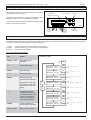

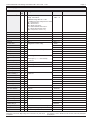


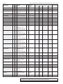
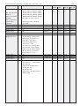


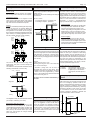
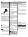
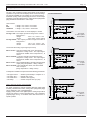

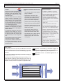

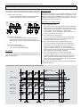
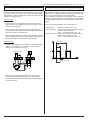

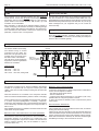
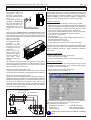


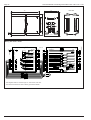
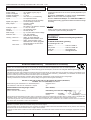

![Maximum Model service Manual.ppt [호환 모드]](http://vs1.manualzilla.com/store/data/006002079_1-f9e925e4876feffe85b493d91263fd66-150x150.png)