1
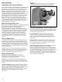
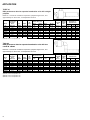
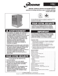
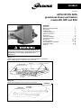
10-204.9
May, 2004
APPLICATION DATA
greenhouse blower unit heaters
models BD, BDP and BSH
Contents
Application . . . . . . . . . . . . . . . . . . . . . . . . . . . . . . . . . . . . .2
Blower Unit Heater Benefits . . . . . . . . . . . . . . . . . . . . . . . .2
Unit Control . . . . . . . . . . . . . . . . . . . . . . . . . . . . . . . . . . . .3
Locating Units . . . . . . . . . . . . . . . . . . . . . . . . . . . . . . . . . . .3
Location Precautions . . . . . . . . . . . . . . . . . . . . . . . . . . . . .3
Selection Procedure . . . . . . . . . . . . . . . . . . . . . . . . . . . . . .4
Unit Layout . . . . . . . . . . . . . . . . . . . . . . . . . . . . . . . . . . . . .9
Polytube Installation . . . . . . . . . . . . . . . . . . . . . . . . . . . . .10
Low Return Air Duct . . . . . . . . . . . . . . . . . . . . . . . . . . . . .10
Dimensions . . . . . . . . . . . . . . . . . . . . . . . . . . . . . . . . .16, 17
Control Systems . . . . . . . . . . . . . . . . . . . . . . . . . . . . .18, 19
Unit Installation & Adjustment . . . . . . . . . . . . . . . . . . . . . .18
Performance Data . . . . . . . . . . . . . . . . . . . . . . . . . . . .12-15
Ordering . . . . . . . . . . . . . . . . . . . . . . . . . . . . . . . . . . . . . .19
WARNING
To prevent premature heat exchanger failure do not
locate ANY gas-fired units in areas where chlorinated,
halogenated, or acid vapors are present in the
atmosphere.
Figure 1.1
Typical polytube heated air distribution under thermal blanket in greenhouse,
reduces heating space, cuts heat loss area, saves fuel.
THERMAL
BLANKET
HEATING AND
RECIRCULATING UNIT
HEATING AND
RECIRCULATING UNIT
POLY-TUBE
(by others)
Figure 1.2
Typical heating application with continuous air circulation.
HEATING AND
RECIRCULATING UNIT
HEATING AND
RECIRCULATING UNIT
POLY-TUBE
(BY OTHERS)
APPLICATION
Applications with Thermal Blankets
Figure 2.1
Centrifugal blower fan with electric motor and adjustable belt
drive. Motor and controls are exposed for easy servicing.
Since most of the heat used in a greenhouse is required at night,
many growers are adding thermal blankets to reduce heating
space and heat loss through the roof of the greenhouse. In
addition there is a strong trend to use under-the-bench heating
systems for greater efficiency and fuel savings. For these
applications Modine offers gas-fired blower-type unit heaters with
a discharge transition for use with polytube for heated-air
distribution below the thermal blanket even down to the ground
level. Blower-type units permit effective air distribution against
static resistances up to 0.4 inches W.C. (0.5" W.C. High
Efficiency II), so they can be suspended above the thermal
blanket, and connected to a polytube via two 90-degree elbows
or thick walled flexible plastic tubing. Operation then can be
controlled with a simple low-cost thermostat located below the
thermal blanket and at plant level.
Wide Size Range Widens Use
Blower-type unit heaters are available in 6 separated combustion
sizes ranging from 130,000 to 340,000 BTU/HR input, 12
standard and High-Efficiency sizes ranging from
50,000 to 400,000 BTU/HR input. The wide range of sizes
enables application in almost any size greenhouse. The addition
of a discharge transition and polytube permits uniform heated
air distribution throughout a variety of greenhouses. With the
versatility of the size range, and the option of overhead or
ground level heated-air distribution, the blower-type heaters
may be applied for total heating of greenhouses, for add-on
or supplemental heating, or, as a standby for other heating
systems.
General Applications
This bulletin covers application, location and selection of gasfired blower-type unit heaters in greenhouse installations only.
Modine propeller and blower-type unit heaters, with a single fan
and electric motor, are most frequently used in commercial and
industrial applications, where natural or propane gas is available.
For further details on these general applications, please refer to
Modine Circular 6-107.
Installation, piping, and venting instructions are covered in a
separate installation and service manual shipped with each unit.
A specific wiring diagram for the ignition control system and
accessories ordered is also shipped with each unit.
Blower Unit Benefits
Greenhouse heating compatibility. With flexibility of
application and fast heating response blower unit heaters
provide healthy and uniform plant growth.
Long-life. Heat exchangers are aluminized steel tubes with
contoured airfoil design to resist corrosion and eliminate noise
during expansion or contraction. Stainless steel heat exchanger
optional.
Lower installation cost. A large selection of motors and drives
allow units to operate efficiently against static resistances as
high as 0.5" W.C., without overloading motor. With longer runs of
polytube substantial savings can be realized on large
installations by reducing number of heaters required. Smaller,
less expensive units are available for use in smaller
greenhouses.
2
Faster warm-up, long throw. No combustion chamber. Flames
burn within individually-fired heat exchanger tubes. Direct firing
into tubes with heat evenly distributed throughout length of tube
results in quicker heat longer heat-throw. Fuel dollars are saved
and comfort is assured at all times.
Less maintenance to keep these units operating at top
efficiency. Aluminized steel burner ports have extra large
openings. Knife-sharp port edges prevent lodging of dirt or
scale…makes burners self-cleaning, thereby reducing cost of
maintenance.
Easier to service. To facilitate servicing, the complete burner
assembly may be removed as a single unit. Casing bottom is
hinged for easy removal and replacement of burner. Controls
are completely exposed for easy access.
Improved combustion efficiency cuts fuel bills. Burner tube
design allows adequate supply of air to reach flame.
Result…fuel dollars are not wasted due to poor design. Further
fuel savings are possible when blower units are equipped with
an optional intermittent pilot control system. The system provides
automatic electric spark ignition of pilot and main burner on
demand for heat. The pilot is lit only as long as thermostat calls
for heat. When thermostat is satisfied, the burner and pilot gas
supply are shut off simultaneously.
APPLICATION
Reliability insured. All performance ratings are the result of
thorough testing. Design of these unit heaters has been certified
by the American Gas Association and Canadian Gas
Association.
4.
Do not locate units in tightly sealed areas or greenhouses
without provisions for adequate combustion air. A free air
inlet area of at least one square inch per 1,000 BTU/HR
input is required.
5.
Do not locate units closer to combustible materials than six
inches to the top, and flue pipe, 18 inches to sides, and 12
inches to the bottom of the unit. Allow adequate clearance
at the bottom of the unit for lowering the hinged bottom
panel for servicing, and at the left hand side of the unit
(facing the front of the unit) for servicing the high
temperature limit control. The minimum distance from
combustible material is based on the combustible surface
not exceeding 160°F. Clearance from the top of the unit and
the flue pipe may be required to be greater than 6" if heat
damage may occur to materials above the unit heater at the
temperature described.
6.
Installation in high humidity or salt-water atmospheres will
cause accelerated corrosion resulting in reduced normal life
of the gas-fired unit heater.
7.
Some plants are susceptible to damage from combustion
flue gases. Make certain an adequate venting system is
provided to prevent flue gases from contacting these plants.
8.
Continuous air circulation is often desirable for greenhouse
heating. If the unit heater motor and blower is cycled, a fandelay switch should be used to allow the heat exchanger to
cool after firing to reduce residual heat that could cause
premature fatigue of the polytube close to the unit heater
discharge opening. Fan-delay switches are provided by
Modine on all low-voltage control systems ordered with the
unit heater.
9.
Gas pressure to unit heater controls must never exceed 14"
W.C. When leak testing piping system with air, be sure that
test pressure does not exceed 14" W.C. if unit heaters are
already installed in system.
Overheating prevented with safety shutdown. At abnormally
high temperatures an internal high limit switch cuts off the burner
gas supply and continues fan operation to cool the heat
exchanger. Switch has automatic reset.
Unit Control
Many greenhouse applications require constant air circulation
and only the heat is cycled as needed, but there are many
installations where the blower is cycled along with the heat and
the system runs intermittently. In the first case, continuous fan
operation, any control system used in conjunction with a
summer/winter switch will accomplish the desired constant fan
operation. For intermittent fan and blower operation, the
standard low-voltage control system or any other optional lowvoltage control system can be used without the need of a
summer/winter switch.
Locating Units
In most greenhouses space for heating equipment is available at
the top and ends of the house. Because Modine blower units are
designed for overhead suspension they are ideal for this
application.
When thermal blankets are used, and for cold climate systems
(outdoor design temperatures less than 20°F) or with tall dense
crops, the use of low-return air ducts is recommended (the lowreturn air duct must be considered when determining total static
pressure of the air distribution system). Modine does not
supply these ducts. They can easily be made locally. The use
of low-return air ducts improves temperature distribution and
promotes circulation of warm air to the bottom of plants and
under benches by drawing the coldest air off the floor. Return
air-duct inlets should be located 18" above floor level. See
Figures 11.1 & 11.2, Page 11, for suggested low air return duct
designs. Blower enclosure kits for connection of low-air return
ducts are available as accessories from Modine. For overhead
heating, air distribution tubes should be located with the
centerlines approximately 8 feet above the floor. This may vary
slightly depending on the greenhouse truss design and
construction details.
Location Precautions
CAUTION
To prevent premature heat exchanger failure, do not locate
any gas fired unit in areas where chlorinated, holagenated,
or acid vapors are present in the atmosphere.
1.
Units installed in personnel-occupied zones (below seven
ft.) must have fingerproof guards covering moving parts
(pulleys, belts, etc.). In addition, high temperature surfaces
such as heat exchanger tubes and flue pipes must be
protected to prevent body contact. In short, anything that
can cause harm to human flesh must be guarded. Modine
does not recommend mounting units lower than seven ft.
measured between the ground and bottom of the unit
heater.
2.
Locate thermostat where it will not be exposed to direct
sunlight or in the path of heated air. A sun shield over the
thermostat may be necessary.
3.
Shield blower bearings from direct exposure to the sun.
Excessive exposure may shorten bearing life.
10. Do not install in potentially explosive or flammable
atmospheres laden with grain dust, sawdust, or similar airborne materials. In such applications a blower type heater
installed in a separate room with ducting to the dust-laden
room is recommended.
11. Avoid installing units in extremely drafty locations. Drafts
cause burner flames to impinge on heat exchangers which
shortens life.
12. Do not install these units outdoors.
13. When thermal blankets are used, be sure provisions are
made to prevent snow buildup, in those areas where heavy
snow loads can be expected, to prevent collapse of
greenhouse structure.
14. See Modine Bulletin 6-553, Installation and Service Manual
PD/BD Models for complete installation details, Bulletin
6-580 for High Efficiency II models, or Bulletin 6-558 for
separated combustion.
3
Figure 4.1
APPLICATION
Quonset style greenhouse dimensions for unit heater size
selection. (For use with Table 4.1)
Selection Procedure
Unit heater sizes are easily selected by determining the
greenhouse exposed surface area, the growing area and the
heat loss requirement. The surface and growing areas are
computed from greenhouse sizes shown in Figures 4.1 and 4.2
and are tabulated in Tables 4.1 and 4.2. The heat loss
requirement is a modification of the exposed surface area to
accommodate the greenhouse condition or construction factor
(“C”), the prevailing wind factor (“W”), and the heat loss factor
for each square foot of the exposed surface area (“F”). See
Tables 5.1, 6.1 and 6.2. The resultant heat loss requirement is
then matched with the compatible heater sizes shown in Tables
7.1 through 8.2.
H
L
W
Table 4.1
quonset style house areas
H = 9.5 ft. W = 20 ft.
L = length
30
40
50
60
70
80
90
100
120
140
160
180
200
Surface Area (ft. )
1154
1450
1746
2042
2338
2634
2930
3226
3818
4410
5002
5594
6186
Growing Area (ft.2)
600
800
1000
1200
1400
1600
1800
2000
2400
2800
3200
3600
4000
2
H = 11.5 ft. W = 30 ft.
L = length
40
50
60
70
80
90
100
110
120
140
160
180
200
Surface Area (ft.2)
2120
2528
2936
3344
3752
4160
4568
4976
5384
6200
7016
7832
8648
Growing Area (ft.2)
1200
1500
1800
2100
2400
2700
3000
3300
3600
4200
4800
5400
6000
Table 4.2
standard style house areas
Hp = 11 ft., He = 7.5 ft., W = 20 ft.
L = length
30
40
50
60
70
80
90
100
120
140
160
180
200
Surface Area (ft.2)
1456
1818
2180
2542
2904
3266
3628
3990
4714
5438
6162
6886
7610
Growing Area (ft.2)
600
800
1000
1200
1400
1600
1800
2000
2400
2800
3200
3600
4000
Hp = 12 ft., He = 7.5 ft., W = 30 ft.
L = length
40
50
60
70
80
90
100
120
140
160
180
200
Surface Area (ft.2)
2438
2901
3364
3827
4290
4753
5216
6142
7068
7994
8920
9846
Growing Area (ft.2)
1200
1500
1800
2100
2400
2700
3000
3600
4200
4800
5400
6000
Hp = 12.5 ft., He = 7.5 ft., W = 40 ft.
L = length
50
60
70
80
90
100
120
140
160
180
200
Surface Area (ft.2)
2974
4132
4690
5248
5806
6364
7480
8596
9712
10828
11944
Growing Area (ft.2)
2000
2400
2800
3200
3600
4000
4800
5600
6400
7200
8000
Figure 4.2
Standard style greenhouse dimensions for unit heater size
selection (For use with Table 4.2)
Hp
peak
He
end
L
4
W
APPLICATION
Table 5.1
Construction “C” factor
Selection Example
A quick selection guide is provided here for typical greenhouse
configurations and may also be used for other greenhouses if
the exposed surface area of the house is known.
Select “C” factor describing greenhouse condition and
construction.
All metal (good tight glass house –
20 or 24 in. glass spacing) . . . . . . . . . . . . . . . . . . 1.03
Design Conditions
Construction
Inside Design Temp.
Outside Design Temp.
Height of House (H)
Width of House (W)
Length of House (L)
Average Wind
Wood and steel (good tight glass house –
16 or 20 in. glass spacing)
(Metal gutters, vents, headers, etc. . . . . . . . . . . . . 1.05
= Quonset style, double
polyethylene covered
= 70°F
= 10°F
= 11.5 ft.
= 30.0 ft.
= 100 ft.
= 15 MPH
Wood houses (glass houses with wood
bars, gutters, vents, etc. – up to and
including 20 in. glass spacing)
Good tight houses . . . . . . . . . . . . . . . . . . . . . . . . . 1.00
Fairly tight houses . . . . . . . . . . . . . . . . . . . . . . . . . 1.13
Loose houses . . . . . . . . . . . . . . . . . . . . . . . . . . . . 1.25
Step 1 – Calculate heat loss requirement using the following
steps.
Fiberglass-covered wood houses . . . . . . . . . . . . . 0.95
a) Determine the exposed surface area using greenhouse
dimensions and house type. For this example Table 4.1 is
used. From Table 4.1 the exposed surface area is shown as
4568 sq. ft.
Plastic-covered metal houses
(single thickness) . . . . . . . . . . . . . . . . . . . . . . . . . 1.00
Fiberglass-covered metal houses . . . . . . . . . . . . . 1.00
Plastic-covered metal houses
(double thickness) . . . . . . . . . . . . . . . . . . . . . . . . . 0.70
Double glazing w/1-in. air space . . . . . . . . . . . . . . 0.70
Surface Area S = 4568 sq. ft.
Exolite covering . . . . . . . . . . . . . . . . . . . . . . . . . . 0.56
b) Determine greenhouse construction correction factor from
Table 5.1. The factor for double poly is 0.70.
Infra-red reflective polyethelyne
(1.77 R value) . . . . . . . . . . . . . . . . . . . . . . . . . . . . 0.57
Construction Factor C = 0.70
c)
Infra-red reflective polyethelyne
(1.4 R value) . . . . . . . . . . . . . . . . . . . . . . . . . . . . . 0.71
Determine wind correction factor from Table 6.1. The wind
correction factor for 15 MPH design average winds is 1.00.
Wind Correction Factor W = 1.00
determined by multiplying the desired cfm/ft2 of growing area
by the total growing area. The total growing area is shown in
Table 4.1 or 4.2 depending on the type of greenhouse. In
this example, Table 4.1 for quonset style greenhouses is
used. The following area is shown as 3000 sq. ft. Calculate
the CFM required as shown below.
d) Determine heat loss factor from Table 6.2. Enter Table 6.2 at
the left hand side and find the inside design temperature.
For this example the inside design temperature is 70°F.
Follow across the table until the column for the outside
design temperature is found. For this example the outside
design temperature is 10°F. The heat loss factor is shown as
67 BTU/HR/Ft2 of surface area.
e) The design heat loss for this example is calculated using the
following equation.
BTU/HR Output = S x C x W x Heat Loss Factor
OR
BTU/HR Output = 4568 Ft2 x 0.70 x 1.00 x 67 BTU/HR/Ft2
BTU/HR Output = 214,239 BTU/HR
Step 2 – Select the correct blower unit heater size to properly
heat the greenhouse by using the following steps.
a) Determine heat loss requirement. From Step 1e this was
found to be 214,239 BTU/HR output.
b) Determine cfm (cubic feet of air per minute) to be handled
by the heating equipment.
Assuming an air circulation requirement of 1.5 cfm per
square foot of growing area the required cfm can be
CFM Required = 3000 sq. ft. x 1.5 cfm/sq. ft.
CFM Required = 4500 CFM
c)
Using the BTU/HR output required (from Step 1e) and the
CFM required (from Step 2b) the correct blower unit heater
model can be selected.
Refer to the Performance Tables on page 7 for standard
and High Efficiency II blower unit heaters, and page 8 for
separated combustion. Assuming two unit heaters per
house, each unit would have to have an output of 107,120
BTU/HR and be capable of delivering 2250 CFM
(determined by dividing the total heat loss and total CFM
required by two).
Two Performance Tables are shown for both standard unit
heaters, High Efficiency II, and separated combustion unit
heaters. One Table is used for applications with straight out
polytubes extending under thermal blankets or for under
bench or ground heating. Select the table which matches the
application requirements of the intended type of installation.
In this example, under-the-bench heating will be used.
d) Enter Table 7.2 for under-bench application, and find a unit
with a BTU/HR output of at least 107,120 BTU/HR. In this
example a BD150 is selected with an output of 120,000
BTU/HR. This is the smallest unit which can be selected
without going under the BTU/HR output required. The
BD150 is capable of delivering 2,020 CFM of air which
nearly matches the required CFM of 2,250 and is acceptable
for this application.
5
APPLICATION
Selection Example (continued)
Table 6.1
wind “W’ factor
Use if average wind velocity exceeds 15 mph during heating season.
Wind Velocity In
Miles Per Hour
15
20
25
30
35
mph or less
mph . . . . . .
mph . . . . . .
mph . . . . . .
mph . . . . . .
.
.
.
.
.
“W”
Factor
.
.
.
.
.
.
.
.
.
.
.
.
.
.
.
.
.
.
.
.
.
.
.
.
.
.
.
.
.
.
.
.
.
.
.
.
.
.
.
.
.
.
.
.
.
.
.
.
.
.
.
.
.
.
.
.
.
.
.
.
.
.
.
.
.
.
.
.
.
.
.
.
.
.
.
.
.
.
.
.
.
.
.
.
.
.
.
.
.
.
.
.
.
.
.
.
.
.
.
.
.
.
.
.
.
.
.
.
.
.
.
.
.
.
.
.
.
.
.
.
.
.
.
.
.
.
.
.
.
.
.
.
.
.
.
.
.
.
.
.
1.00
1.04
1.08
1.12
1.16
Based on 70° ³ T inside/outside air.
Table 6.2
heat requirements /BTU/HR per ft.2 surface area for glass
F°
Inside
Temperature
40
45
50
55
60
65
70
75
“C” = 1.0, “W” = 1.0
°F Outside Design Temperature
-30
70
86
92
99
105
112
119
126
-25
73
79
86
92
99
105
112
119
-20
67
73
79
86
92
99
105
112
-15
61
67
73
79
86
92
99
105
-10
54
61
67
73
79
86
92
99
-5
49
54
61
67
73
79
86
92
Since the BDP150 High Efficiency II has the same performance,
it too is acceptable for this application.
Step 3 – Determine correct blower motor horsepower and
blower drive requirements.
Blower unit heaters have variable pitch drives and different
horsepower / drive combinations which can be used to achieve
varying CFMs at different external static pressures. It is
necessary to select the correct horsepower and drive
combinations based on the configuration of the installation, the
amount of polytube or duct work used with the unit, the CFM to
be delivered and the total external static pressure of the system.
Tables 7.1 through 8.2 show some typical installation
configurations and the horsepower/drive combination required
based on these configurations only.
To determine the correct horsepower/drive combination use the
following steps.
a) Refer to the corresponding performance table for the unit
being selected and the installation configuration. For this
example under-the-bench heating is being used. Table 7.2
shows that a BD150 delivering 2,020 CFM with under-thebench heating would require a 1/2 horsepower motor in
combination with a -96 drive package. If a blower enclosure
was used in addition to the unit, a 1/2 horsepower motor with
a -96 drive package would have to be selected.
6
0
43
49
54
61
67
73
79
86
5
38
43
49
54
61
67
73
79
10
33
38
43
49
54
61
67
73
15
27
33
38
43
49
54
61
67
20
22
27
33
38
43
49
54
61
25
16
22
27
33
38
43
49
54
30
11
16
22
27
33
38
43
49
35
6
11
16
22
27
33
38
43
Step 4 – Determine the minimum hole area required for the
polytube, the polytube size and the number of holes required
depending on whether 2", 2-1/2", or 3" holes are to be punched
in the polytube.
a) Refer to Tables 7.1 through 8.2 for the minimum hole area
and number of holes required to meet the minimum hole area
requirement. For this example the minimum hole area is 2.13
square feet and, if 2-1/2" holes are used, it would require that
a minimum of 62 holes be punched in the polytube.
Step 5 – Determine installation layout. For this determination
refer to Figure 9.1 on page 9 for Typical Installation Layouts.
APPLICATION
Table 7.1
BD/BDP performance data for standard units with straight polytube
Based on 1.5 cfm/ft2 air circulation requirement, polytube length 150 ft., and
approximately 0.2’ W.C.E.S.P., air temperature rise 55°F.
Model
No.
BD/BD50
BD/BDP75
BD/BDP100
BD/BDP125
BD/BDP150
BD/BDP175
BD/BDP200
BD/BDP250
BD/BDP300
BD/BDP350
BD/BDP400
Growing Area
Coverage
Sq.Ft.
Each Unit
449
673
898
1123
1347
1571
1796
2245
2693
3143
3591
Input
BTU/HR
50,000
75,000
100,000
125,000
150,000
175,000
200,000
250,000
300,000
350,000
400,000
Output
BTU/HR
40,000
60,000
80,000
100,000
120,000
140,000
160,000
200,000
240,000
280,000
320,000
Air
Flow
(cfm)
673
1010
1347
1684
2020
2357
2694
3367
4040
4714
5387
Without Blower
Enclosure
With Blower
Enclosure & Filter
Motor
H.P.
1/4
1/3
1/3
1/2
1/3
3/4
1/2
3/4
1-1/2
2
3
Motor
H.P.
1/4
1/2
1/2
3/4
1/2
3/4
1/2
1
1-1/2
2
3
Blower
Dr. No.
-183
-185
-90
-211
-95
-192
-101
-205
-106
-210
-111
Blower
Dr. No.
-183
-187
-91
-199
-96
-192
-101
-205
-106
-210
-111
Polytube
Dia.
Inches
12
12
12
18
18
18
18
18
24
24
24
Needed
Polytube
Hole
Area, Ft2
0.71
1.06
1.42
1.77
2.13
2.48
2.84
3.54
4.25
4.96
5.67
Polytube
Dia.
Inches
12
12
12
18
18
18
18
18
24
24
24
Needed
Polytube
Hole
Area, Ft2
0.71
1.06
1.42
1.77
2.13
2.48
2.84
3.54
4.25
4.96
5.67
Needed No. of
Polytube Holes
3" dia. 2½" dia. 2" dia.
14
22
32
22
32
50
30
42
66
36
52
82
44
62
98
52
74
114
58
84
130
72
104
162
88
126
196
102
146
228
116
166
260
Table 7.2
BD/BDP performance data for standard units with two round 90°
elbows
Based on 1.5 cfm/ft2 air circulation requirement, polytube length 150 ft., and
approximately 0.3’ W.C.E.S.P., air temperature rise 55°F.
Model
No.
BD/BDP50
BD/BDP75
BD/BDP100
BD/BDP125
BD/BDP150
BD/BDP175
BD/BDP200
BD/BDP250
BD/BDP300
BD/BDP350
BD/BDP400
Growing Area
Coverage
Sq.Ft.
Each Unit
449
673
898
1123
1347
1571
1796
2245
2693
3143
3591
Input
BTU/HR
50,000
75,000
100,000
125,000
150,000
175,000
200,000
250,000
300,000
350,000
400,000
**
Output
BTU/HR
40,000
60,000
80,000
100,000
120,000
140,000
160,000
200,000
240,000
280,000
320,000
Air
Flow
(cfm)
673
1010
1347
1684
2020
2357
2694
3367
4040
4714
5387
Without Blower
Enclosure
Motor
H.P.
1/4
1/2
1/2
1/2
1/2
3/4
1/2
3/4
1-1/2
2
3
Blower
Dr. No.
-183
-186
-92
-211
-96
-192
-101
-205
-106
-210
-111
With Blower
Enclosure & Filter
Motor
H.P.
1/3
3/4
1/2
3/4
1/2
1
3/4
1
1-1/2
3
3
Blower
Dr. No.
-1
-187
-91
-199
-96
-192
-16
-205
-106
-111
-111
Needed No. of
Polytube Holes
3" dia. 2½" dia. 2" dia.
14
22
32
22
32
50
30
42
66
36
52
82
44
62
98
52
74
114
58
84
130
72
104
162
88
126
196
102
146
228
116
166
260
7
APPLICATION
TABLE 8.1
BSH performance data for separated combustion units with straight
polytube
Based on 1.5 cfm/ft2 air circulation requirement, polytube length 150 ft., and
approximately 0.2’ W.C.E.S.P., air temperature rise 55°F.
Growing Area
Coverage
Model
Sq.Ft.
No.
Each Unit
BSH130
1197
BSH130➀
1097
BSH150
1381
BSH170
1565
BSH225
2045
BSH280
2577
BSH340
3091
BSH340➀
2833
➀
Input
BTU/HR
130,000
130,000
150,000
170,000
225,000
280,000
340,000
340,000
Output
BTU/HR
106,600
106,600
123,000
139,400
182,250
229,600
275,400
275,400
Air
Flow
(cfm)
1795
1645
2071
2347
3068
3865
4636
4250
With or Without
Blower Enclosure
Motor
H.P.
1/3
1/3
1/2
1/2
3/4
1-1/2
2
2
Blower
Dr. No.
-15
-15
-25
-22
-18
-23
-32
-32
With Filter
Motor
H.P.
–
1/3
1/2
1/2
3/4
1-1/2
–
2
Blower
Dr. No.
–
-15
-22
-22
-18
-23
–
-32
Polytube
Dia.
Inches
18
18
18
18
24
24
24
24
Needed
Polytube
Hole
Area, Ft2
1.89
1.73
2.18
2.47
3.23
4.07
4.88
4.47
Polytube
Dia.
Inches
18
18
18
18
24
24
24
24
24
Needed
Polytube
Hole
Area, Ft2
1.73
1.48
2.18
2.47
3.23
4.07
3.73
4.47
4.13
Needed No. of
Polytube Holes
3" dia. 2½" dia. 2" dia.
38
56
88
36
52
80
44
64
100
50
72
114
66
96
148
84
120
186
100
144
224
92
132
206
Based on 60°F air temperature rise.
Table 8.2
BSH performance data for separated combustion units with two
round 90° elbows
Based on 1.5 cfm/ft2 air circulation requirement, polytube length 150 ft., and
approximately 0.3’ W.C.E.S.P., air temperature rise 55°F.
Model
No.
BSH130➀
BSH130➂
BSH150
BSH170
BSH225
BSH280
BSH280➀
BSH340➀
BSH340➁
Growing Area
Coverage
Sq.Ft.
Each Unit
1097
940
1381
1565
2045
2577
2362
2833
2615
Input
BTU/HR
130,000
130,000
150,000
170,000
225,000
280,000
280,000
340,000
340,000
➀ Based on 60°F air temperature rise.
➁ Based on 65°F air temperature rise.
➂ Based on 70°F air temperature rise.
8
Output
BTU/HR
106,600
106,600
123,000
139,400
182,250
229,600
229,600
275,400
275,400
Air
Flow
(cfm)
1645
1410
2071
2347
3068
3865
3543
4250
3923
Wtih or Without
Blower Enclosure
Motor
H.P.
1/3
1/3
1/2
3/4
3/4
1-1/2
1-1/2
2
2
Blower
Dr. No.
-15
-15
-22
-18
-18
-23
-23
-32
-32
With Filter
Motor
H.P.
–
1/3
1/2
3/4
1
–
1-1/2
–
2
Blower
Dr. No.
–
-15
-22
-18
-16
–
-23
–
-32
Needed No. of
Polytube Holes
3" dia. 21/2" dia. 2" dia.
36
52
80
30
44
68
44
64
100
50
72
114
66
96
148
84
120
186
76
110
172
92
132
206
84
122
190
APPLICATION
Figure 9.1
Typical Blower Unit Heater Installation Layouts
Single Unit House Arrangement
House Width less than 20',
Length less than 150'
Two Unit House Arrangement
House Width less than 20',
Length more than 150'
Two Unit House Arrangement
House Width more than 20',
Length less than 150'
Four Unit House Arrangement
House Width greater than 20',
Length more than 150'
Three Unit House Arrangement
House Width greater than 30',
Length less than 150'
Six Unit House Arrangement
House Width greater than 30',
Length more than 150'
9
APPLICATION
Tube Installation
Polyethylene air distribution tubes, available at most greenhouse
supply houses, are not furnished by Modine. The tube can be
simply and directly connected to the heater outlet transition with
a gasket and clamp, as illustrated in Figure 10.1. The clamp and
gasket are shipped with the Modine transition. Maximum
recommended mounting height of polytube from floor is nine feet.
To install:
1. Remove clamp.
2. Thread tube end through the clamp about 2 to 4 inches.
3.
4.
5.
6.
Orient the tube so the holes will provide proper air
distribution as shown in either Figures 2 or 3, depending on
application.
Fit tube end and clamp over the gasketed outlet transition
and secure clamp with screwdriver.
Unroll tube to length desired and tie up end opposite heater.
Add intermediate hangers as required.
Figure 10.1
Figure 10.2
Polytube installed on outlet transition
Hoops and Key rings suspending deflated polytube (All items
shown are by installer).
Figure 10.3
Inflated polytube during heating/ventilating cycle.
Low Return – Air Ducting
An extended low return-air duct is recommended for attachment
to the blower enclosure when winter design temperature is lower
than 20°F or when thermal blankets are used. This ducting will
improve heated air distribution and aid circulation of warm air to
the bottom of plants and under benches by drawing the colder
air from the floor area. This circulation also reduces warm air
stratification near the top of the greenhouse thus lowering overall
heat loss and fuel consumption. Return - air ducts should extend
to about 18 inches from the floor in an open area to facilitate air
recirculation.
10
Figures 11.1 and 11.2 show two possible methods for installing
low-air return ducts with Modine blower model unit heaters.
Figure 11.1 utilizes the optional Modine blower enclosure kit and
a field fabricated return duct. Figure 11.2 shows an alternate
field fabricated blower enclosure and return air duct.
IF THE MODINE BLOWER ENCLOSURE IS NOT USED AND
THE BLOWER COVER IS FIELD FABRICATED, DIMENSIONS
B, C, AND D MUST BE MAINTAINED FOR THE RESPECTIVE
UNIT HEATER MODELS TO ALLOW CLEARANCE FOR THE
BLOWER/MOTOR ASSEMBLY AND PROPER AIR ACCESS TO
THE BLOWER FAN WHEEL.
APPLICATION
Figure 11.2
Figure 11.1
Field fabricated blower enclosure kit with bottom-mounted
return-air duct
Modine blower enclosure kit with rear-mounted return-air duct.
A
A
C
B
C
B
TURNING
VANES
ENCLOSURE
(OPT.)
E
D
D
F
BLOWER ENCLOSURE
DUCT FLANGE
LOW-AIR RETURN
DUCT AND
BLOWER COVER
(BY INSTALLER)
LOW-AIR
RETURN DUCT
(BY INSTALLER)
18"
GROUND LEVEL
18"
GROUND LEVEL
Install Modine blower enclosure kit according to installation
instructions packaged with kit. Attach field fabricated low-air
return duct as illustrated in Figure 11.2.
It is recommended that turning vanes be used if the method
shown in Figure 11.2 is used. Turning vanes will help reduce
static losses in the duct and promote good air flow to the blower
fan.
When covering blower assembly, provide removable access
panels on both sides of the blower to allow for servicing and
adjustment of blower assembly. If the Modine blower enclosure
is used, the side panels are removable for this purpose if
installed as shown in Figure 11.2. If the method in Figure 11.1 is
used, the installer is responsible for providing service access
panels.
1. Fabricate cover and return air duct as shown. Dimensions B,
C, and D must be maintained for the respective model sizes
for proper clearances.
2. Provide access panels on both sides of the blower cover to
allow for service and drive adjustment. Make panels large
enough for easy access to motor and drive components.
Table 10
Blower cover dimensions
Model
BD50
A
approx.
36-3/4
B
C
E
F
22
BD/BDP 75
42
22
17-1/2 14-1/8
16
15-3/4
17-1/2 17-1/8
16
15-3/4
BD/BDP 100
45
25
21-1/4 17-1/8 19-3/4
15-3/4
BD/BDP 125
47
25
21-1/4 21-3/8 19-3/4
20
BD/BDP 150
BD/BDP 175
52
30
BD/BDP 200
BD/BDP 250
BD/BDP 300
59
34
34-1/4 25-1/8 32-3/4
23-3/4
BD/BDP 350
BD/BDP 400
59
34
44-3/8 25-1/8 42-7/8
23-3/4
29
D
21-3/8 27-1/2
20
Do not enclose any of the gas or electrical controls and provide
sufficient room for servicing these controls.
Modine blower model unit heaters have suspension supports on
the blower housing as well as the unit heater. Clearance holes
must be provided for suspending the unit from the blower
housing. The Modine blower enclosure kit is provided with
clearance holes.
11
WARRANTY
Seller warrants its products to be free from defects in material and workmanship,
EXCLUSIVE, HOWEVER, of failures attributable to the use of materials substituted
under emergency conditions for materials normally employed. This warranty covers
replacement of any parts furnished from the factory of Seller, but does not cover
labor of any kind and materials not furnished by Seller, or any charges for any
such labor or materials, whether such labor, materials or charges thereon are due
to replacement of parts, adjustments, repairs, or any other work done. This
warranty does not apply to any equipment which shall have been repaired or
altered outside the factory of Seller in any way so as, in the judgment of Seller, to
affect its stability, nor which has been subjected to misuse, negligence, or
operating conditions in excess of those for which such equipment was designed.
This warranty does not cover the effects of physical or chemical properties of water
or steam or other liquids or gases used in the equipment.
BUYER AGREES THAT SELLER’S WARRANTY OF ITS PRODUCTS TO BE
FREE FROM DEFECT IN MATERIAL AND WORKMANSHIP, AS LIMITED
HEREIN, SHALL BE IN LIEU OF AND EXCLUSIVE OF ALL OTHER
WARRANTIES, EITHER EXPRESS OR IMPLIED, WHETHER ARISING FROM
LAW, COURSE OF DEALING, USAGE OF TRADE, OR OTHERWISE, THERE
ARE NO OTHER WARRANTIES, INCLUDING WARRANTY OF
MERCHANTABILITY OR FITNESS FOR PURPOSE, WHICH EXTEND BEYOND
THE PRODUCT DESCRIPTION CONFIRMED BY BUYER AND SELLER AS OF
THE DATE OF FINAL AGREEMENT.
This warranty is void if the input to the product exceeds the rated input as
indicated on the product serial plate by more than 5% on gas-fired and oil-fired
units, or if the product in the judgment of SELLER has been installed in a corrosive
atmosphere, or subjected to corrosive fluids or gases, been subjected to misuse,
negligence, accident, excessive thermal shock, excessive humidity, physical
damage, impact, abrasion, unauthorized alterations, or operation contrary to
SELLER’S printed instructions, or if the serial number has been altered, defaced or
removed.
Heat Exchangers
For Seller’s non-separated combustion Gas-Fired Unit Heaters
BUYER’S REMEDY FOR BREACH OF WARRANTY, EXCLUSIVE OF ALL
OTHER REMEDIES PROVIDED BY LAW, IS LIMITED TO REPAIR OR
REPLACEMENT AT THE FACTORY OF SELLER, ANY HEAT EXCHANGER
WHICH SHALL, WITHIN TEN YEARS FROM DATE OF FIRST BENEFICIAL
USE BY BUYER OR ANY OTHER USER, WITHIN TEN YEARS FROM DATE
OF RESALE BY BUYER OR ANY OTHER USER, WITHIN TEN YEARS
FROM DATE OF RESALE BY BUYER IN ANY UNCHANGED CONDITION,
OR WITHIN ONE HUNDRED TWENTY-SIX MONTHS FROM DATE OF
SHIPMENT FROM SELLER, WHICHEVER OCCURS FIRST, BE RETURNED
TO SELLER WITH TRANSPORTATION CHARGES PREPAID AND WHICH
THE EXAMINATION OF SELLER SHALL DISCLOSE TO HAVE BEEN
DEFECTIVE; EXCEPT THAT WHEN THE PRODUCT IS TO BE USED BY
BUYER AS A COMPONENT PART OF EQUIPMENT MANUFACTURED BY
BUYER, BUYER’S REMEDY FOR BREACH, AS LIMITED HEREIN, SHALL
BE LIMITED TO ONE YEAR FROM DATE OF SHIPMENT FROM SELLER.
FOR GAS-FIRED PRODUCTS INSTALLED IN HIGH HUMIDITY
APPLICATIONS AND UTILIZING STAINLESS STEEL HEAT EXCHANGERS,
BUYER’S REMEDY FOR BREACH, AS LIMITED HEREIN, SHALL BE
LIMITED TO TEN YEARS FROM DATE OF SHIPMENT FROM SELLER.
For Seller's Low Intensity Gas-Fired Infrared Heaters
BUYER'S REMEDY FOR BREACH OF WARRANTY, EXCLUSIVE OF ALL
OTHER REMEDIES PROVIDED BY LAW, IS LIMITED TO REPAIR OR
REPLACEMENT AT THE FACTORY OF SELLER, ANY HEAT EXCHANGER
WHICH SHALL, WITHIN FIVE YEARS FROM DATE OF FIRST BENEFICIAL
USE BY BUYER OR ANY OTHER USER, WITHIN FIVE YEARS FROM DATE
OF RESALE BY BUYER OR ANY OTHER USER, WITHIN FIVE YEARS
FROM DATE OF RESALE BY BUYER IN ANY UNCHANGED CONDITION,
OR WITHIN 66 MONTHS FROM DATE OF SHIPMENT FROM SELLER,
WHICHEVER OCCURS FIRST, BE RETURNED TO SELLER WITH
TRANSPORTATION CHARGES PREPAID AND WHICH THE EXAMINATION
OF SELLER SHALL DISCLOSE TO HAVE BEEN DEFECTIVE; EXCEPT THAT
WHEN THE PRODUCT IS TO BE USED BY BUYER AS A COMPONENT
PART OF EQUIPMENT MANUFACTURED BY BUYER, BUYER'S REMEDY
FOR BREACH, AS LIMITED HEREIN, SHALL BE LIMITED TO ONE YEAR
FROM DATE OF SHIPMENT FROM SELLER.
Heat Exchanger (Condensers) for all Seller’s products except nonseparated combustion Gas-Fired Unit Heaters and Infrared Heaters, all
Burners except Infrared Heaters, and Sheet Metal for all Seller's products
BUYER’S REMEDY FOR BREACH OF WARRANTY, EXCLUSIVE OF ALL
OTHER REMEDIES PROVIDED BY LAW, IS LIMITED TO REPAIR OR
REPLACEMENT AT THE FACTORY OF SELLER, ANY HEAT EXCHANGER
(CONDENSER) OR BURNER WHICH SHALL, WITHIN ONE YEAR FROM
DATE OF FIRST BENEFICIAL USE BY BUYER OR ANY OTHER USER,
WITHIN ONE YEAR FROM DATE OF RESALE BY BUYER IN ANY
UNCHANGED CONDITION, OR WITHIN EIGHTEEN MONTHS FROM DATE
OF SHIPMENT FROM SELLER, WHICHEVER OCCURS FIRST, BE
RETURNED TO SELLER WITH TRANSPORTATION CHARGES PREPAID
AND WHICH THE EXAMINATION OF SELLER SHALL DISCLOSE TO HAVE
BEEN DEFECTIVE; EXCEPT THAT WHEN THE PRODUCT IS TO BE USED
BY BUYER AS A COMPONENT PART OF EQUIPMENT MANUFACTURED
BY BUYER, BUYER’S REMEDY FOR BREACH, AS LIMITED HEREIN,
SHALL BE LIMITED TO ONE YEAR FROM DATE OF SHIPMENT FROM
SELLER.
Burners
For Seller's Low Intensity Gas-Fired Infrared Heaters
BUYER'S REMEDY FOR BREACH OF WARRANTY, EXCLUSIVE OF ALL
OTHER REMEDIES PROVIDED BY LAW, IS LIMITED TO REPAIR OR
REPLACEMENT AT THE FACTORY OF SELLER, ANY BURNER WHICH
SHALL, WITHIN TWO YEARS FROM DATE OF FIRST BENEFICIAL USE BY
BUYER OR ANY OTHER USER, WITHIN TWO YEARS FROM DATE OF
RESALE BY BUYER IN ANY UNCHANGED CONDITION, OR WITHIN 30
MONTHS FROM DATE OF SHIPMENT FROM SELLER, WHICHEVER
OCCURS FIRST, BE RETURNED TO SELLER WITH TRANSPORTATION
CHARGES PREPAID AND WHICH THE EXAMINATION OF SELLER SHALL
DISCLOSE TO HAVE BEEN DEFECTIVE; EXCEPT THAT WHEN THE
PRODUCT IS TO BE USED BY BUYER AS A COMPONENT PART OF
EQUIPMENT MANUFACTURED BY BUYER, BUYER'S REMEDY FOR
BREACH, AS LIMITED HEREIN, SHALL BE LIMITED TO ONE YEAR FROM
DATE OF SHIPMENT FROM SELLER.
For Seller's High Intensity Gas-Fired Infrared Heaters
BUYER'S REMEDY FOR BREACH OF WARRANTY, EXCLUSIVE OF ALL
OTHER REMEDIES PROVIDED BY LAW, IS LIMITED TO REPAIR OR
REPLACEMENT AT THE FACTORY OF SELLER, ANY BURNER WHICH
SHALL, WITHIN TEN YEARS FROM DATE OF FIRST BENEFICIAL USE BY
BUYER OR ANY OTHER USER, WITHIN TEN YEARS FROM DATE OF
RESALE BY BUYER IN ANY UNCHANGED CONDITION, OR WITHIN 126
MONTHS FROM DATE OF SHIPMENT FROM SELLER, WHICHEVER
OCCURS FIRST, BE RETURNED TO SELLER WITH TRANSPORTATION
CHARGES PREPAID AND WHICH THE EXAMINATION OF SELLER SHALL
DISCLOSE TO HAVE BEEN DEFECTIVE; EXCEPT THAT WHEN THE
PRODUCT IS TO BE USED BY BUYER AS A COMPONENT PART OF
EQUIPMENT MANUFACTURED BY BUYER, BUYER'S REMEDY FOR
BREACH, AS LIMITED HEREIN, SHALL BE LIMITED TO ONE YEAR FROM
DATE OF SHIPMENT FROM SELLER.
All Other Components Excluding Heat Exchanger (Condenser), Burner,
and Sheet Metal
For all Seller's products except Direct-Fired Heaters and High Intensity
Gas-Fired Infrared Heaters
BUYER’S REMEDY FOR BREACH OF WARRANTY, EXCLUSIVE OF ALL
OTHER REMEDIES PROVIDED BY LAW, IS LIMITED TO REPAIR OR
REPLACEMENT AT THE FACTORY OF SELLER, ANY PART OR PARTS
WHICH SHALL, WITHIN TWO YEARS FROM DATE OF FIRST BENEFICIAL
USE BY BUYER OR ANY OTHER USER, WITHIN TWO YEARS FROM DATE
OF RESALE BY BUYER IN ANY UNCHANGED CONDITION, OR WITHIN
THIRTY MONTHS FROM DATE OF SHIPMENT FROM SELLER,
WHICHEVER OCCURS FIRST, BE RETURNED TO SELLER WITH
TRANSPORTATION CHARGES PREPAID AND WHICH THE EXAMINATION
OF SELLER SHALL DISCLOSE TO HAVE BEEN DEFECTIVE; EXCEPT THAT
WHEN THE PRODUCT IS TO BE USED BY BUYER AS A COMPONENT
PART OF EQUIPMENT MANUFACTURED BY BUYER, BUYER’S REMEDY
FOR BREACH, AS LIMITED HEREIN, SHALL BE LIMITED TO ONE YEAR
FROM DATE OF SHIPMENT FROM SELLER.
For Seller's Direct-Fired Heaters and High Intensity Gas-Fired Infrared Heaters
BUYER’S REMEDY FOR BREACH OF WARRANTY EXCLUSIVE OF ALL
OTHER REMEDIES PROVIDED BY LAW IS LIMITED TO REPAIR OR
REPLACEMENT AT THE SELLER’S OPTION ANY PART OR PARTS WHICH
SHALL WITHIN A PERIOD OF ONE YEAR FROM DATE OF FIRST
BENEFICIAL USE BY BUYER OR ANY OTHER USER, WITHIN ONE YEAR
FROM DATE OF RESALE BY BUYER IN ANY UNCHANGED CONDITION,
OR WITHIN 18 MONTHS FROM DATE OF SHIPMENT FROM SELLER,
WHICHEVER OCCURS FIRST, BE RETURNED TO SELLER WITH
TRANSPORTATION CHARGES PREPAID AND WHICH THE EXAMINATION
OF THE SELLER SHALL DISCLOSE TO HAVE BEEN DEFECTIVE.
BUYER AGREES THAT IN NO EVENT WILL SELLER BE LIABLE FOR COSTS
OF PROCESSING, LOST PROFITS, INJURY TO GOODWILL, OR ANY OTHER
CONSEQUENTIAL OR INCIDENTAL DAMAGES OF ANY KIND RESULTING
FROM THE ORDER OR USE OF ITS PRODUCT, WHETHER ARISING FROM
BREACH OF WARRANTY, NONCONFORMITY TO ORDERED
SPECIFICATIONS, DELAY IN DELIVERY, OR ANY LOSS SUSTAINED BY THE
BUYER.
As Modine Manufacturing Company has a continuous product improvement program, it
reserves the right to change design and specifications without notice.
Commercial HVAC&R Division
Modine Manufacturing Company
1221 Magnolia Avenue
Buena Vista, Virginia 24416
Phone: 1.800.828.4328 (HEAT)
Fax: 540.261.1903 (Service & Parts)
www.modine.com
© Modine Manufacturing Company 2004
4/04 - M Litho in USA