1
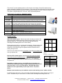
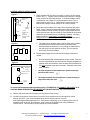
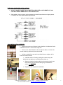
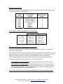
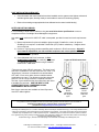
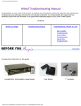
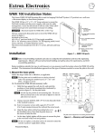
Oasis Qt™ Sound Masking System
INSTALLATION GUIDE
CRITICAL STEPS TO UNDERSTAND BEFORE INSTALLATION
This Installation Guide is intended to provide all information necessary for a successful installation.
Please read the Guide thoroughly before beginning installation for the first time. With the Oasis Qt™
system, a successful installation is easy! Following these critical steps will save you time.
•
Use only specified materials. If it is necessary to create custom cables, follow the Custom
Cabling instructions exactly (see Notes on Custom Cabling at the end of this document).
•
Install emitters with the control module turned ON. Volume and application settings should
be as described below:
•
o
Connect a working control module to the emitter string to test as you install. If lack
of power in a tel/data closet during construction forces you to shortcut the first homerun
and test the emitters with a control module hooked up to the first emitter – it is absolutely
critical to test the homerun cable before installation and to test the system output once
again when power is available.
o
Set remote control and Volume DIP switch on highest volume during installation.
Set Application DIP switch to position 1 for installation. This will make it easy to hear the
sound masking sound and identify any emitters that are not working properly. Return
the Application DIP switch to the default position 2 once installation is complete.
Confirm correct operation of each emitter before proceeding to next emitter.
o
If an emitter is not working, check that emitter and the connecting cables to ensure all are
installed correctly. If these changes do not correct the issue, the problem likely exists
within the previous 4 emitters or connecting cables (because of the 4-channel system).
For details, see the Troubleshooting Guide at www.cambridgesoundmanagement.com or
in the reseller kit.
o
FIX ANY PROBLEMS BEFORE MOVING FORWARD TO THE NEXT EMITTER. DO
NOT PROCEED WITH INSTALLATION UNTIL ALL ISSUES ARE RESOLVED.
•
Do not connect more than 60 emitters or exceed a line length of 1000 feet on any homerun.
•
Install Open Offices and Private Offices on separate zones.
•
Walk through the entire space when installation is complete, listening to each emitter with
your ear tilted upwards toward the ceiling to confirm each emitter is operating correctly.
•
Set Application and Volume settings to appropriate levels as described at the end of this
Installation Guide.
Cambridge Sound Management / 27 Moulton Street / Cambridge, Massachusetts 02138
617/349-3779 or 800/219-8199 / www.cambridgesoundmanagement.com
12.06
The Oasis Qt™ sound masking system is a four-channel, low-voltage, “direct field” speech privacy
system, suitable for installation in any workspace. This system will reduce distractions in open plan areas
and ensure confidential speech privacy in enclosed offices, conference rooms, or patient waiting rooms.
The system is plug-and-play and – once set – rarely requires adjustments.
VERIFY THAT YOU HAVE ALL REQUIRED PARTS:
1
1
4 per Emitter
Kit Ordered
SPS control module
UL-rated modular power supply for control module
4 per Emitter
Kit Ordered
1
2 Pairs
1
1
1
16-foot patch cables terminated with RJ-45 connectors for connection
between emitters, quantity same as number of emitters supplied less one.
Hole saw for drilling hole in ceiling tile
Screws and plastic anchors for wall-mounting SPS control module
Infrared remote control
Control module labeling kit
Monitor emitter & mounting bracket (optional)
Electric drill (not supplied)
Acoustic emitters for mounting in suspended ceiling tile, quantity as ordered
SYSTEM LAYOUT:
Open office emitter layout: Plan the layout with a drawing or sketch of the
ceiling that shows potential interfering elements such as lights, HVAC vents,
sprinkler heads, etc. (This layout may have been planned already by
Cambridge Sound Management or the local reseller.)
D
D
Emitter spacing should be on a square grid (see sketch). Grid dimensions will
vary based on ceiling height. (see Table 1.) An individual emitter may be
moved up to 2 feet from this grid if its planned location interferes with an
existing ceiling element.
The first row of emitters should be no less than 1 foot and no more than 5 feet
from any adjacent wall.
Table 1.
Grid size vs. Ceiling Height
Enclosed office emitter layout: Note that open office areas and closed
office areas must be on separate zones. For enclosed offices up to 150
square feet, install two emitters per office within 1.5’ – 2.5’ of diagonal
corners. For larger offices, install one additional emitter for each additional
75 square feet.
Depending on emitter spacing, a single SPS-30 control module can
provide sound masking coverage for approximately 3,000 square feet of
open plan space, or up to 15 private offices. One SPS-300 control
module can cover approximately 30,000 square feet or 150 private
offices.
Ceiling
Height (ft)
8
8.5
9
10
12
Other
Height, H
Emitter
Spacing, D
8
10
10
10
12
Call for
details
Multiple control modules may be installed to create sound masking “zones” within a facility.
For detailed layout instructions, refer to Cambridge Sound Management’s System Planning and Layout
Guide – available from your local reseller or online at www.cambridgesoundmanagement.com.
Cambridge Sound Management / 27 Moulton Street / Cambridge, Massachusetts 02138
617/349-3779 or 800/219-8199 / www.cambridgesoundmanagement.com
2
CONTROL MODULE INSTALLATION:
Figure 1:
Location of
tile for first
emitter
Initial 16 ft.
Cat –5 cable
Wall
Dropped
Ceiling
Control
Module with
cable
connected
through a wall
opening
1. Select a location for the control unit within 16 feet of the first emitter
location (Fig. 1). Typically, control modules are housed in a storage
closet or other out-of-the-way location. If mounting multiple control
modules near one another, it is recommended to leave 1 foot of
space between each (Fig. 2). Otherwise the remote control may
inadvertently change volume settings on all control modules.
2. Mount the control module on the wall near a convenient AC power
outlet. Figure 3 shows a typical wall elevation with possible control
module locations. Route an initial 16-foot (or longer) cable from the
ceiling location where the first emitter is to be installed to the location
where the control module will be permanently installed. If a longer
cable is needed, it must conform to Cambridge Sound
Management’s custom cabling specifications detailed at the end of
this document.
•
Figure 2:
1’
1’
The cable can be dressed where it will be visible using a plastic,
self-sticking wire channel such as those manufactured by
Wiremold (www.wiremold.com), or by pulling the cable down in
the wall cavity to a hole drilled in the wall. The hole may be
covered by the control module.
3. Plug the power supply into the wall and into the back of the control
module.
1’
•
Figure 3:
Dropped
ceiling
Possible control
unit location
Power
Outlet
Do a trial assembly with 4 emitters and the control module. Insert one
end of a 16-foot cable into one of the two RJ-45 output receptacles on
the back of the control module. Insert the other end of the cable into
the input receptacle on the top of an emitter. Repeat for each of the
other 3 emitters.
•
The input receptacle of each emitter has a symbol showing an
input arrow into a circle:
•
The output receptacle of each emitter has a symbol showing an
output arrow out of the circle:
To ensure that subsequent emitters operate properly, IT IS ESSENTIAL TO CONNECT THE OUTPUT OF A
CONTROL MODULE OR EMITTER TO THE INPUT OF THE NEXT EMITTER. This is not a safety issue.
4. Remove the plastic tab from the battery housing of the remote control.
5. Aim the infrared remote control at the front of the control module and cycle through all 8 volume
settings, plus OFF. (See Volume Settings at the end of this document or online at
www.cambridgesoundmanagement.com.) Verify that a “whooshing” or air conditioning-like sound is
emitted by each of the four test speakers. Keep volume at the highest level during installation –
Volume Step 8. This will help to quickly identify any emitter problems.
Cambridge Sound Management / 27 Moulton Street / Cambridge, Massachusetts 02138
617/349-3779 or 800/219-8199 / www.cambridgesoundmanagement.com
3
6. If the control module will be installed outside of the actual workspace it covers (i.e. in a supply closet),
it is recommended to install the optional monitor emitter next to each control module. Use the metal
mounting bracket if one has been provided. A monitor emitter allows you to easily confirm setting
changes without being directly in the workspace.
7. Fill out the label in the control module kit and mount on or near the control module. Labeling is
essential in a facility with multiple zones, or when several control modules are mounted next to one
another. Include the phone number of your local reseller or installer.
EMITTER INSTALLATION:
8. Remove and gather all ceiling tiles that are to receive an emitter.
9. Using the supplied hole saw and a pre-drilled tile as a template, cut holes in each ceiling tile that will
receive an emitter. Cut in the center of a 2’ x 2’ tile. In other tile sizes, install as appropriate to
achieve required spacing. It is recommended that you cut all tiles at once to save time. If there is no
suspended ceiling, visit www.cambridgesoundmanagement.com or
contact your local reseller for other installation options.
10. Install each emitter in its respective tile. To install an emitter, gently push
the emitter through the hole from the front of the tile. Install the nut by
turning it slowly counter-clockwise while simultaneously pushing it down
until it slips tightly into the back of the ceiling tile. Twist the nut clockwise
to lock it in place.
11. Place the 16-foot patch cables between the openings in the ceiling grid where the tiles are to be reinstalled. Provide strain relief or cable hangers as required by local code. See sketch below.
A
B
C
D
Pre-positioned Cat –
3 cables
Dropped
Ceiling
Wall
Control Module with cable
connected through a wall
opening
12. Install ceiling tiles outward from the control module (i.e. moving from A to D in the sketch above).
Connect the output cable from one emitter to the input jack of the next emitter.
13. Before moving to the next emitter, verify that each emitter is operating normally as you
connect the cables. Listen for a “whooshing” sound.
Occasionally the emitter layout needs to be adjusted during installation to account for sprinkler heads or
other barriers not on the drawings. An individual emitter may be moved up to 2 feet (or 1 tile) in any
direction from the layout plan.
Cambridge Sound Management / 27 Moulton Street / Cambridge, Massachusetts 02138
617/349-3779 or 800/219-8199 / www.cambridgesoundmanagement.com
4
NOTES ON LARGER AREA INSTALLATIONS:
•
DO NOT CONNECT MORE THAN 60 EMITTERS OR EXCEED A LINE LENGTH OF 1,000
FEET ON A SINGLE HOME RUN TO THE CONTROL UNIT.
•
Cable splitters, 2-way or 4-way, may be necessary to meet this requirement on larger systems.
For details, refer to the Splitter Model Diagram below.
QUICK INSTALLATION OVERVIEW:
• Assuming a sequence of emitters is being installed - with A as the first tile
and B as the second - remove both ceiling tiles.
• Throw a 16 ft. cable from B to A. A now has two cables – one from the
control module (or previous tile) and one from B.
• Using the supplied hole saw and a pre-drilled tile as a template, drill a
hole in the center of tile A.
• Install the emitter in tile A by pushing the emitter through the
drilled hole and slipping on and twisting the locking nut.
•
Back on the ladder, plug the cable from the previous location into
tile A emitter input jack and the cable going to tile B into the
emitter output jack.
•
Replace tile A to complete the installation.
Cambridge Sound Management / 27 Moulton Street / Cambridge, Massachusetts 02138
617/349-3779 or 800/219-8199 / www.cambridgesoundmanagement.com
5
APPLICATION AND VOLUME SETTINGS:
Two system settings are required to provide the appropriate level of sound masking for any given
environment: the Application setting and the Volume setting.
•
Application setting is made via the dual-in-line (DIP) switch on the back of the Oasis
Qt™ control module. This has been pre-set to the appropriate setting. Do not adjust.
•
Volume setting is made in two steps:
• First via the DIP switch on the control module
• Secondly via the remote control
Setting the DIP switches:
Two DIP switches are located on the back of the Oasis Qt™ control module. (See diagram.)
•
The Application switch (on the left) is pre-set and requires no adjustment.
•
The Volume switch (on the right) must be adjusted depending on the environment.
Switch positions (Position 1 or Position 2) can be changed using a ballpoint pen or small
screwdriver. Push down on the top of the switch to change a switch to position 1. Push down on the
bottom of the switch to change a switch to position 2.
Cambridge Sound Management / 27 Moulton Street / Cambridge, Massachusetts 02138
617/349-3779 or 800/219-8199 / www.cambridgesoundmanagement.com
6
Setting the Volume Level:
The Oasis Qt™ system has 8 volume steps achieved through combinations of DIP switch positions
and remote control volume level settings:
Volume
steps
(low to high)
step 1
step 2
step 3
step 4
step 5
step 6
step 7
step 8
Volume
DIP switch
position
position 2 (default)
position 2 (default)
position 2 (default)
position 2 (default)
position 1
position 1
position 1
position 1
Volume
Remote Control
Setting
1
2
3
4
1
2
3
4
Recommended Volume Settings Based on Ceiling Height:
Ceiling Height
8’ - 8’11”
9’ - 10’11”
11’ - 12’11”
13’ - 14”
> 14’
Volume Steps
Open Office
Private Office
Step 4 or 5
Step 2 or 3
Step 5 or 6
Step 2 or 3
Step 5 or 6
Step 2 or 3
Step 6 or 7
Step 2 or 3
call for details
call for details
Recommended Volume Settings Based on Performance:
If you have a sound level meter, the ideal sound level in private offices is 42 dB. The ideal sound
level in open areas is 46 dB.
If you do not have a sound level meter, have someone in the adjacent private office speak. If you can
distinguish what they are saying, increase the volume to improve privacy. In an open area, you will
still hear some speech, but there should be a noticeable difference in the effort required to
understand the speaker when the sound masking system is set at the appropriate volume level.
Some personal preference may be involved in the volume-setting decision.
•
For installation in new construction: Initial volume setting should be the specified setting.
•
For installation in occupied spaces: Initial volume setting should be two (2) steps below the
recommended level. Volume levels should be increased one step every 5 – 10 days, when few
or no employees are present. This allows all employees to acclimate to the new background
sound and significantly improves user acceptance.
Once volume level has been set, fill in Volume Setting field on the control module label(s).
Cambridge Sound Management / 27 Moulton Street / Cambridge, Massachusetts 02138
617/349-3779 or 800/219-8199 / www.cambridgesoundmanagement.com
7
POST INSTALLATION CHECK-OUT:
•
Once all emitters and control modules have been installed, turn the system to the highest volume and
walk through the space, listening closely to each emitter to ensure it is functioning properly.
•
Reset volume settings to appropriate levels as indicated on the control module label(s).
NOTES ON CUSTOM CABLING:
If it is necessary to build custom cables on site, you must follow these specifications to ensure
compliance with the Cambridge Sound Management equipment.
Any quality solid conductor 24 AWG CAT cable is acceptable, provided it meets local code requirements
and:
1) Meets requirements for plenum installation (plenum-rated) if installed in a return air plenum.
Shielding is not required. Unshielded Twisted Pair (UTP) cable is satisfactory. Snagless boots
are not required.
2) Has bent* 3-tyne (prong) contacts straddling each conductor in RJ-45 connectors. Aligned 2tyne contacts intended for use with stranded conductors are not acceptable under any
circumstances. Failure to follow this requirement will result in intermittent contact and
inconsistent system operation.
3) Once fabricated with RJ-45 connector, is fieldtested before installation for continuity, shorts and
1:1 (straight through) connection using a standard
network CAT cable tester.
2 types of RJ-45 connectors:
*There are two types of RJ-45 connectors. The “bent 3-tyne”
connector is intended for use with solid core CAT cable. The
“aligned tyne” connector is intended for use with stranded
CAT cable. Errors occur when incorrect cable/connector
combinations are used. The diagram to the right shows the
end on a view of a single contact in a modular connector.
The bent 3-tyne contact has the tines offset from each other
to straddle the conductor. USE THE BENT 3-TYNE
CONNECTOR FOR ALL CAMBRIDGE SOUND
MANAGEMENT INSTALLATIONS.
Bent 3-tyne connectors are available at Home Depot and
most CAT cable suppliers.
INCORRECT
RJ-45
connector
with aligned
tyne
CORRECT
RJ-45
connector
with bent
tyne
Any questions concerning installation of Oasis Qt™ sound masking systems should be directed to your local reseller or:
Cambridge Sound Management / 27 Moulton Street / Cambridge, MA 02138
(617) 349-3779 / [email protected]
TM
Cambridge Sound Management, LLC, located in Cambridge, MA, is the developer of Qt Quiet technology , a low-voltage distributed audio
system for sound masking, paging and background music distribution in the workplace. Our systems are sold direct and by select partners
worldwide; they are deployed in over 7 million square feet of space. Installations range from modest home offices to spaces of unlimited
size. Applications range from providing acoustical comfort in open workspaces to settings such as doctor’s offices, where sound masking is
used to ensure confidential speech privacy.
TM
TM
Qt Quiet technology , Oasis Qt and Qt Quietpage™ are trademarks of Cambridge Sound Management, LLC.
Cambridge Sound Management / 27 Moulton Street / Cambridge, Massachusetts 02138
617/349-3779 or 800/219-8199 / www.cambridgesoundmanagement.com
8