1
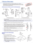
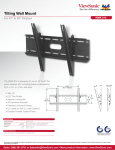
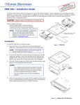
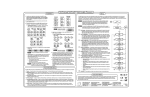
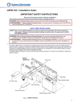
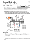
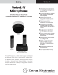
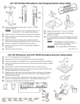
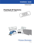
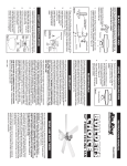
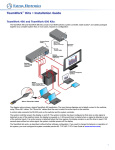
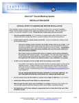
WMK 100 Installation Notes
The Extron WMK 100 Wall Mounting Kit is used for hanging PoleVault® System A/V products on a wall near
a flat screen display or short throw projector.
The WMK 100 has a 13" x 13" x 2.5" deep enclosure to mount the
PoleVault switcher and the power supply, with room for cable
management. It also has knockouts on all four sides which allow
external raceways to be used where necessary for cabling.
(4) 1/4-20 x 2"
Pan Head Bolts
#40-375-01
C Maximum load for the WMK 100 is 15 lbs (7 kg).
The key components (base plate and cover) of the WMK 100 are
shown in figure 1.
Included in the kit are:
(4) ¼-20 x 2" pan head bolts, (4) ¼" Kap toggle assemblies,
(4) ¼ x 1¾" masonry screws, (4) #14 x 1¾" self tapping metal/wood
screws, (4) 6-32 x ¼" button head hex screws.
Not shown but included are (3) 4-40 x ¼" screws, (2) hook-and-loop
straps.
(4) 1/4" Kap Toggle Assemblies
#40-374-01
(4) 1/4" x 1 3/4" Masonry Screws
#40-373-01
(4) #14 x 1 3/4" Self-tapping
Metal/Wood Screws
#40-372-01
(4) 6/32" x 1/4" Button Head
Hex Screws
#40-363-17LF
Installation
N Refer to local building standards and codes to verify that the installation will meet the regulatory
requirements. Observe all local and national building and safety codes, UL requirements, and ADA
accessibility guidelines.
Before installation identify the type of wall (masonry or non-masonry) and the location where the WMK 100 will be
installed. This determines the installation approach and the type of fasteners needed to secure the plate to the wall.
1.Mount the base plate
WMK 100
Base Plate
Follow the steps within 1A or 1B below, as applicable.
N The base plate can be installed over an existing electrical
outlet. The opening fits standard sized 2.75" x 4.5" wall
plates. See figure 2 (inset).
1A. To mount the WMK 100 onto masonry walls:
i.
Mounting Cutout for
Holes
Signal Cable
Access
Marker for
Level Pilot Hole
Hold the base against the wall, level it, and mark the
positions of four slotted mounting holes (indicated by
+ marks in figure 2). Set the plate aside.
N Use the top slot position at each mounting hole. Do not use
both top and left slots as this will make it difficult to slide the
plate down (see step iv).
ii. Using a masonry drill bit, drill 1.75" (4.4 cm) deep pilot holes
at the marked locations.
iii. Screw in masonry screws until a gap of 1/8" to 3/8"
(3 to 9 mm) remains between the wall and the screw heads.
iv. Align the base plate's slotted mounting holes over
the installed screws, then slide the plate down so
the screws fit into the slots.
+
+
v. At this time, lightly tighten all the screws to secure the plate
to the wall and verify level and position.
Cutout for
Electrical
Outlet
The plate can be aligned over an existing electrical outlet.
Figure 2 — Masonry wall mounting
N Do not over tighten, as the plate needs to be removed to attach the
switcher and power supply before cabling.
Proceed to Step 2.
68-1738-01
Rev A
06 09
1
PRELIMINARY
Figure 1 — WMK 100 parts
WMK 100 Installation Notes, cont'd
1B. To mount the WMK 100 onto a non-masonry wall:
i.
At the desired site locate the wall studs and mark their
locations.
WMK 100
Base Plate
Mounting Cutout for
Holes
Signal Cable
Access
Marker for
Level Pilot Hole
N For ideal installation secure the base plate to at least one
wall stud (see figure 3). Drywall Kap toggles can be used
for holes not aligned with studs.
The base plate can be installed over an existing electrical
outlet. The opening fits standard sized 2.75" x 4.5" wall
plates. See inset on figure 2.
ii. Hold and level the base plate against the wall and mark
the positions of the slotted mounting holes that are on
the stud lines (see figure 3, indicated by + marks). Where
applicable, mark the mounting holes on the wall for
drywall toggles. Set the plate aside.
iii. Drill 1.75" (4.4 cm) deep pilot holes at the marked
locations.
PRELIMINARY
iv. Insert the self tapping screws into the pilot holes, until a
gap of 1/8" to 3/8" (3 to 9 mm) remains between the wall
and the screw heads.
N If using toggle assemblies see figure 4 for installation
method.
v. Align the base plate's slotted mounting holes
over the installed screws, then slide the plate
down so the screws fit into the slots.
+
Wall Studs
Cutout for
Electrical
Outlet
Figure 3 — Non-masonry wall mounting
a. Grasp handle, collapse
toggle and insert into wall.
b. Slide plastic washer
down into pilot hole.
c. Cut off handle close to wall.
d. Hand screw in pan head
bolt until 1/8" gap remains.
+
vi. At this time, lightly tighten all the screws to ensure plate
fits flush to the wall and verify level and position.
N Do not over tighten, as the plate needs to be removed to
attach the switcher and power supply before cabling.
vii. If the cables are to be run behind the wall to the WMK
location, mark the cutout area on the wall for the signal
cable access hole (see figure 3).
Figure 4 — Toggle assembly installation
viii.Remove the base plate and cut out the marked area.
2.Mount the switcher and power supply
c. Re-attach the plate to the wall and secure firmly.
PAGING
SENSOR
SENSITIVITY
SIGNAL
NORMAL
PVS 305SA
PEAK
MIC
VOICELIFT
SIGNAL
AUDIO LEVEL ADJUST
NORMAL
PEAK
INPUT
5
AUX AUDIO
4
3
INPUT SELECTION
2
CONFIG
1
b. Attach the power supply above the electrical outlet cutout,
with the supplied hook-and-loop straps. Attach it so the cables
are easily and safely routed to the electrical outlet and switcher
alike.
POLEVAULT SWITCHER
a. Remove the WMK 100 base plate from the wall, and with the
switcher's rear ports facing the cable access hole, align
the two corner holes in the base of the switcher with the two
outermost device mounting holes in the WMK 100 base plate.
Secure with the supplied 440 x ¼" screws.
(2) 4-40 x 1/4" screws
Figure 5 — Attach switcher and power
supply to base plate
2
3.Run cables
700
Run signal cables from the proposed PoleVault input wall plates,
control device location, and the speakers to the WMK 100 location.
Cables can be routed behind the walls, or through a surface raceway
(e.g., Wiremold 700 or 2400 series) directly to the WMK 100.
2400
Raceway Option
3A. If running cable behind the walls:
i.
Run all the cables from the various locations to the WMK and
through the access hole.
3B. If using a surface raceway:
i.
Attach the WMK cover to the base plate, then identify and
mark the most suitable raceway entrance to the WMK 100.
ii. Run the raceway from the signal source, speaker, and display
locations to the marked raceway entrance at the WMK.
iii Remove the WMK cover, and remove the desired knockout.
iv. Attach the raceway to the wall and run cables from the sources
and outputs through the raceway to the WMK.
Signal Cable Access
Cutout Option
PRELIMINARY
Figure 6 — Cabling run options
4.Cable the switcher
a. Connect the cables from the PoleVault transmitters, control device
(MediaLink® Controller), speakers, and optional accessories (VoiceLift, Page Sensor Kit) to the rear ports of the
switcher (see below). Refer to the PVS 305SA Setup Guide for additional details.
N If using a device other than a PVS 305SA (e.g., PVS 204SA Plus), refer to that device's user manual for details.
b. Run VGA and composite video cables from the switcher to the output display device through the wall or
where fitted, the raceway.
c. Connect the power supply to the switcher and plug it in to the electrical outlet.
N If the electrical outlet is outside the WMK, pass the IEC power cable out through one of the raceway knockouts.
RGB signal input
(2 CAT 5 cables, A and B
with RJ-45 connectors)
RGB #1B
Red
Black
a
MONITOR OUT
S G
IR OUT
Wire Color PVS Terminal
(left and right)
AUDIO
OUT
COMPUTER IN
RGB #1A
N15779
1ARGB
RGB
1A
PVT RGB D Plus
Power
Connector
External
Power Supply
(12 VDC, 5 A max.)
2A
2ARGB
RGB
3A
3A RGB
RGB
4A
4ARGB
RGB
®
POWER
k
12V
5A MAX
OUTPUTS
RGB
1BRGB
RGB
1B
2B
2B RGB
RGB
3B RGB
3
VIDEO
/VIDEO
VIDEO
VOICELIFT
RECEIVER
4B
4B RGB
RGB
4/VIDEO
VIDEO
b
AMPLIFIED AUDIO OUT
DO NOT
GROUND
OR SHORT
2/4/8
SPEAKER
Ohms
OUTPUTS
L
R
CLASS 2 WIRING
LINE OUT
17TT
AUDIO/VIDEO
APPARATUS
US
LISTED
I
N
P
U
T
S
L
R
L
R
10V
e
c j
i
50mA
CONTROL
Tx Rx IR
12V
PAGING
RS-232 MLC/IR
SENSOR VOL/MUTE
AUX AUDIO
INPUT 5
d
Positive (+)
Negative (-)
f
g
h
RS-232 Control
Composite video input
(CAT 5 cable with
RJ-45 connector)
VGA
Connector
VIDEO #3
IN
Audio output
to speakers
Line out output
(audio)
Aux Audio
Input 5
VoiceLift
Receiver
RGB output
to display
Composite
video output
to display
VIDEO IN
AUDIO IN
L
Paging
Sensor
RCA
Connector
R
S G
IR OUT
PVT CV D
Cabling the switcher
+12 VDC
Ground ( )
Ground ( )
Receive (Rx) B
Transmit (Tx) A
MLC
Wire Colors
A (Rx)
White
B (Tx)
Violet
Ground Drain Wire
Ground Black
12V In
Red
PVS Switcher
A (Tx)
B (Rx)
D (Ground)
D (Ground)
E +12 V
DISPLAY
ON
VCR
OFF
DVD
VOLUME
PC
1
2
3
CONFIG
4
MLC 104 IP PLUS
3
WMK 100 Installation Notes, cont'd
5.Final installation.
a. After completion of cabling, place the cover over the installed plate,
and secure at each corner with the provided 6-32 button head screws.
SENSITIVITY
SIGNAL
PAGING
SENSOR
NORMAL
PVS 305SA
PEAK
MIC
VOICELIFT
SIGNAL
AUDIO LEVEL ADJUST
NORMAL
5
AUX AUDIO
INPUT
PEAK
b. Switch on the display device, control device, signal sources and
adjust and configure the system as needed.
POLEVAULT SWITCHER
N Ensure any cables exiting the box (e.g., to display device and
external electrical outlet) pass through a raceway knockout.
3
CONFIG
1
2
INPUT SELECTION
4
For full configuration and setup details, refer to the PoleVault System
Installation Manual, the MLC 104 Plus Series Reference Manual, and the
PVS 305SA User's Manual, all available online at www.extron.com.
General Specifications
Mounting
Wall mount������������������������� Yes, with included hardware
Figure 7— Attach WMK 100 cover
Maximum load capacity��������������� 15 lbs (6.8 kg)
Material������������������������������������������� Steel
Dimensions
Base plate���������������������������� 12.8" H x 12.8" W x 0.5" D (32.5 cm H x 32.5 cm W x 1.3 cm D)
Cover����������������������������������� 13.0" H x 13.0" W x 2.5" D (33.0 cm H x 33.0 cm W x 6.4 cm D)
Product weight������������������������������ 4 lbs (1.8 kg)
Shipping weight���������������������������� 6 lbs (3 kg)
Vibration����������������������������������������� ISTA 1A in carton (International Safe Transit Association)
Regulatory compliance
Safety����������������������������������� c-UL, UL
Warranty����������������������������������������� 3 years parts and labor
N
Specifications are subject to change without notice.
Both Sides
Top View
Both Sides
12.83"
(32.59 cm)
Both
Sides
2.5"
(6.35 cm)
13"
(33.02 cm)
Side View
Side View
13"
(33.02 cm)
12.83"
(32.59 cm)
Base
Extron USA - West
Headquarters
+800.633.9876
Inside USA / Canada Only
+1.714.491.1500
+1.714.491.1517 FAX
4
Extron USA - East
Extron Europe
Extron Asia
Extron Japan
Extron China
Extron Middle East
+800.633.9876
+800.3987.6673
+800.7339.8766
+81.3.3511.7655
+81.3.3511.7656 FAX
+400.883.1568
+971.4.2991800
+971.4.2991880 FAX
+1.919.863.1794
+1.919.863.1797 FAX
+31.33.453.4040
+31.33.453.4050 FAX
+65.6383.4400
+65.6383.4664 FAX
Inside USA / Canada Only
Inside Europe Only
Inside Asia Only
© 2009 Extron Electronics. All rights reserved.
Inside China Only
+86.21.3760.1568
+86.21.3760.1566 FAX