1
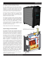
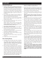
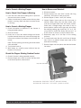
Empyre Pro Series Models 200 and 400 Installation and Operation Instructions Phase II Wood Gasifier TABLE OF CONTENTS Introduction.......................................................................................................................................................... 3–4 The Empyre Pro Series Hot Water Furnace.....................................................................................................3 How The Empyre Pro Series Works..................................................................................................................3 Model & Serial Number Information................................................................................................................4 Safety.................................................................................................................................................................... 5–7 Safety Precautions............................................................................................................................................5 Safety Alert Symbol...........................................................................................................................................6 Signal Words......................................................................................................................................................6 Safety Decals.....................................................................................................................................................6 Features.................................................................................................................................................................... 8 Indentifying Main Components........................................................................................................................8 Unit Dimensions ...............................................................................................................................................8 Installation.........................................................................................................................................................9–16 Minimum Clearance to Combustibles.............................................................................................................9 Suggested Material Required to Complete an Installation............................................................................9 Installation Requirements................................................................................................................................9 Foundation Dimensions.................................................................................................................................10 Trench for Underground Pipes........................................................................................................................10 Outdoor Furnace Installation......................................................................................................................... 11 Outdoor Chimney Installation........................................................................................................................ 11 Indoor Chimney Installation.......................................................................................................................... 11 Supplying Make Up Air................................................................................................................................... 11 Low Water Temperature Protection.............................................................................................................. 12 Empyre System Optimizer............................................................................................................................. 12 Water Line Hookup......................................................................................................................................... 12 Electrical Hookup........................................................................................................................................... 12 Auxiliary Heat (Water to Water)......................................................................................................................14 Side Arm Installation...................................................................................................................................... 15 Optional Heat Exchanger............................................................................................................................... 15 First Fill............................................................................................................................................................16 Maintaining Proper Water Level.....................................................................................................................16 Operation......................................................................................................................................................... 16–19 Starting the Fire in the Hot Water Wood Furnace.........................................................................................16 Maintaining Proper Water Temperature........................................................................................................16 Understanding the Gasification Process.......................................................................................................17 Identifying Smoke Versus Condensation.......................................................................................................17 Loading Wood into the Firebox.......................................................................................................................17 Daily Routine.................................................................................................................................................. 18 Cleaning Out Ash............................................................................................................................................ 18 Disposal of Ash............................................................................................................................................... 19 Creosote - Formation and Need for Removal............................................................................................... 19 Fire Brick & Insulation................................................................................................................................... 19 EMPYRE PRO SERIES INSTALLATION AND OPERATION MANUAL 1 TABLE OF CONTENTS Operation con’t............................................................................................................................................... 16–19 Blower Draft Setting....................................................................................................................................... 19 Loading Door.................................................................................................................................................. 19 Power Outages............................................................................................................................................... 19 Maintenance.......................................................................................................................................................... 20 During Heating Season.................................................................................................................................. 20 End of Heating Season.................................................................................................................................. 20 Reference........................................................................................................................................................ 21–24 Operating the Digital Temperature Switch (DTS)......................................................................................... 21 Hot Water Wood Furnace Wiring Diagram - Empyre Pro Series 200 and 400 .......................................... 22 How to Correct a Sticking Flapper ................................................................................................................ 23 Furnace Specifications.................................................................................................................................. 24 Troubleshooting.............................................................................................................................................. 25–26 Warranty.................................................................................................................................................. Back Cover 2 EMPYRE PRO SERIES INSTALLATION AND OPERATION MANUAL INTRODUCTION The Empyre Pro Series Hot Water Furnace You have selected one of the best wood stoves/ furnaces on the market today! It has been specially designed to produce highly efficient heat with emissions well below environmental standards, and we are proud to offer a 10 year limited warranty! To ensure maximum benefit from your new Empyre Pro Series furnace, read the Installation and Operation Instruction Manual cover to cover and follow all instructions carefully. The Empyre Pro Series furnace has been designed for outdoor installation and has also been tested to meet UL Standard 391 - 2006/726-06 Standard C22.2 No.3 and CSA B366-1-M91 for indoor central solid fuel fired furnaces, therefore it may be installed indoors. It is ideally suited for both domestic and commercial use. Please keep this manual for future reference. How The Empyre Pro Series Works MODEL Empyre Pro Series 200 The Empyre Pro Series uses a process called wood gasification to produce highly efficient combustion in the furnace’s dual burn chambers. (1) Wood in the firebox burns from the bottom up, drying the top layer of wood in the firebox and forcing gases and exhaust into the lower burn chamber. (2) In the brick-lined lower chamber, these volatile gases are burned at temperatures as high as 2000°F (1093°C).* The firebrick lining in both burn chambers absorbs the heat and maintains burn chamber temperatures for consistent gas combustion. This high-temperature gas combustion significantly lowers emissions, prevents creosote buildup, and minimizes ash buildup in the unit. (3) After passing through the burn chamber, exhaust air escapes through multiple flues running through the water jacket, heating the water quickly and efficiently. (4) The exhaust cools as it passes through the flues, and when it leaves the chimney, temperatures have fallen to 350°F (177°C). *varies based on fuel type, burn rate and other conditions Read more on gasification on page 17. EMPYRE PRO SERIES INSTALLATION AND OPERATION MANUAL 3 INTRODUCTION Model & Serial Number Information Locate and record the model number and serial number in the space provided. See page 7 (item #2) for location of decal on furnace. Have this information available when contacting the dealer for service, warranty or other information. 817547R00 EMPYRE PRO SERIES HYDRONIC FURNACE Solid Fuel Fired Furnace FOURNAISE À EAU CHAUDE SÉRIE EMPYRE PRO Fournaise à combustible solide Model No./Modèle □ 200 □ 400 Certified Heating Appliance Serial No./ N° de Série ___________________________________ :CAN/CSA B366.1-M91 (R2002):UL 391 (2006):UL 391 (Mar 2010):UL 391 (Sept 2010):CAN/CSA B366.1 (R2011) Appareil de Chauffage Certifiée : CAN/CSA B366.1-M91 (R2002) : UL 391 (2006) : UL 391 (mars 2010) : UL 391 (sept. 2010) : CAN/ CSA B366.1 (R2011) Certified as an add-on model February 2010. Certifiée comme modèle complémentaire, février 2010. Electrical ratings: volts 120, 1 phase, 60HZ, 15 amps max. Combustion Blowers: Empyre Pro Series 200 #702112153 or #702111396, Empyre Pro Series 400 #70625938. Base - Noncombustible, concrete preferred. Fuel - Burn wood only. Classification électriques: 120 volts, courant monophasé, 60 Hz, maximum de 15 ampères. Ventilateurs de combustion: série Empyre Pro 200 no 702112153 ou no 702111396, série Empyre Pro 400 no 70625938. Plate-forme – Non combustible, de préférence en béton. Combustible – Brûler saulement que du bois. Manufactured by Pro-Fab Industries Inc. Made in Canada 4 WN16796 Fabriqué par Pro-Fab Industries Inc. Fabriqué au Canada EMPYRE PRO SERIES INSTALLATION AND OPERATION MANUAL SAFETY Safety Precautions • The Empyre Pro Series furnace is designed to work in conjunction with another heat source. We recommend this furnace not to be used as a stand alone unit. Should the system fail or run out of wood, a backup system should be in place. • For best efficiency and cleanest burn use only seasoned fire wood. NEVER burn trash, tires, solvents, plastics, engine oil, gasoline or other flammable liquids, rubber, naptha, household garbage, material treated with petroleum products (particle board, railroad ties and pressure treated, painted, or kiln dried wood), leaves, paper products, or cardboard. • Start the fire with paper and small kindling. • The Empyre Pro Series furnace is designed to operate under atmospheric pressure only. ALWAYS keep the vent cap / water level indicator loose over the vent opening. Do not seal or clamp down the vent cap. • Keep area around the furnace clean at all times to avoid possible fire hazards. Adhere to installation clearance and restrictions. • The Empyre Pro Series rear access door is equipped with a latch locking bolt. Because of an electrocution hazard and hot surfaces keep children away. ALWAYS secure door with latch locking bolt and tighten bolt with wrench. • Read the manual carefully and read all decals on the Empyre Pro Series furnace. Should you have any questions not answered in this manual, contact your dealer. WARNING: EXPLOSIVE GASES Gases formed during solid-fuel combustion may cause a small explosion when the furnace is refueled. Door Opening Instructions: 1. Switch blower off when flames are present. 2. Stand back behind door. 3. SLOWLY open door. 4. Wait for smoke to clear (30 seconds). Close door if smoke continues. 5. Open door fully. 6. After loading, always close and latch door firmly. 7. Switch blower on. CAUTION! Keep children a safe distance from the furnace. • DO NOT use chemicals, gasoline, oil or any other combustible fluid to start the fire. • DO NOT store fuel or combustible materials within the installation clearance area. • DO NOT connect the unit to a chimney flue that serves another appliance. • DO NOT burn trash in this furnace. • DO NOT pressurize water in furnace. • DO NOT damage furnace. Load wood carefully. • DO NOT run furnace with water level below add mark. • DO NOT operate the furnace below a temperature of 165°F (74°C). This is important in order to maintain the warranty. • DO NOT dump ash close to any combustible materials. • DO NOT operate with loading or ash removal doors open. • DO NOT add fuel during a power outage. • DO NOT allow ash and creosote buildup. Furnace must be kept in good condition. Follow cleaning instructions in the Installation and Operation Instruction Manual. • DO NOT use with an automatic stoker unless so certified. • DO NOT modifiy this unit in any way. Any modification will void the warranty. In the event of loss of electrical power: 1. Open all flow-check and zone valves in the system. Depending on system design, this may allow convective circulation. 2. It is important to remember that the heating system cannot dispose of a great deal of heat without the circulators running. Avoid over-firing! DO NOT LOAD LARGE AMOUNTS OF SOLID FUEL INTO THE FURNACE! Fire the furnace cautiously until it is determined how quickly the heat system is able to dissipate the heat being produced by the furnace. 3. When the power has returned, reset all flow-check and zone valves and resume normal operation of the system. In the event of a runaway fire: 1. Ensure the firebox door is tightly closed. 2. Close all the combustion air inlets on the furnace. To cool an overheated furnace: 1. Turn all thermostats to their highest temperature setting. EMPYRE PRO SERIES INSTALLATION AND OPERATION MANUAL 5 SAFETY Safety Alert Symbol Safety Decals The Safety Alert symbol identifies important safety messages in the manual and on the furnace. When this symbol is present, be alert to the possibility of injury or death. Follow all instructions in the safety message given. This symbol means attention, be alert, and your safety is involved. Please read and follow directions to ensure safe practices when using the Empyre Pro Series furnace. Why is SAFETY important to you? Three very important reasons: 1. Accidents disable and kill. 2. Accidents cost. 3. Accidents can be avoided. Signal Words Note the use of the signal words: DANGER, WARNING and CAUTION with the safety messages. The appropriate signal word has been selected using the following guidelines: DANGER 1)DANGER/WARNING/CAUTION Safety Instructions: Located on the front right corner below controls. 2) FURNACE SERIAL DECAL - Located on the front right corner above controls. 3)ELECTRICAL/INSTALLATION: Installer Information - Located on outside edge of rear access door. 4) CAUTION: THIS LID IS HEAVY. USE BOTH HANDS. LID AREA MAY BE VERY HOT. SWITCH BLOWER OFF BEFORE OPENING. - Located on centre back fly ash / flue clean out cover. 5) WARNING: ELECTROCUTION HAZARD. Always secure door with latch. Tighten with wrench. Located on rear access door above latch. 6) PRO SERIES 200/400 - Located on right side of furnace on control panel door. 7) SPECIFICATIONS - Located on outside edge of rear access door. DANGER: Indicates an imminently hazardous situation that, if not avoided, WILL result in death or serious injury if proper precautions are not taken. WARNING WARNING: Indicates a potentially hazardous situation that, if not avoided, COULD result in death or serious injury if proper precautions are not taken. CAUTION CAUTION: Indicates a potentially hazardous situation that, if not avoided, MAY result in minor or moderate injury if proper practices are not taken, or serves as a reminder to follow appropriate safety practices. 6 EMPYRE PRO SERIES INSTALLATION AND OPERATION MANUAL SAFETY 1. 3. DANGER ! Risk of fire or explosion. DO NOT start or fuel the fire using garbage, gasoline, drain oil or other flammable liquids or chemicals. ! For use with aluminum or copper conductors. EMPYREPRO PROSERIES SERIES HYDRONIC EMPYRE HYDRONICFURNACE FURNACE Solid Fuel Fired Furnace FOURNAISE À EAU CHAUDE SÉRIE EMPYRE PRO Fournaise à combustible solide □ 100 □ 200 □ 400 Serial No./ N° De Série ___________________________ Model ed No./Modèle 200 □ 400CSA Standard B366-1-M91 Serial No./ N° de391-2006/726-06 Série ___________________________________ Certifi Heating □ Appliance UL Standard Standard C22.2 No. 3 Appareil De Chauffage B366-1-M91 De(R2002):UL La CSA Norme 391 De391 ULC - 2006 2006/726-06 Norme C22.2 No 3 Certified Heating Appliance Norme :CAN/CSA B366.1-M91 391 (2006):UL (Mar 2010):UL 391 (Sept 2010):CAN/CSA B366.1 (R2011) Certified as an add-on model October 2007. - Name__________________________ _______________________________ - Date of Installation_______________ Classification électriques: 120 volts, Hz, maximum deou 15no ampères. Procourant Seriesmonophasé, 100/200 60 no702112153 702111396, Pro Series 400 no 70625938 Ventilateurs de combustion: série Empyre Pro 200 no 702112153 ou no 702111396, série Empyre Pro 400 no 70625938. Plate-forme – Non combustible, de préférence en béton. Combustible – Brûler saulement que du bois. 815543 - Fabriqué par Pro-Fab Industries Inc. Fabriqué au Canada - 2 Side Wall to Furnace 12” (305 mm) Back Wall to Furnace 36” (914 mm) Front of Furnace to Combustibles 48” (1220 mm) Combustibles to Flue 12” (305 mm) Ceiling to Furnace 33” (838 mm) !! - INSTALLER INFORMATION: Address________________________ WN16796 Minimum Clearance to Combustibles 815555 An annual inspection by a qualified service technician is recommended. Certified as an add-on model 2010. comme modèle complémentaire, février 2010. Pro February Series 100/200 #702112153 orCertifiée #702111396, Pro Series 400 #70625938 Manufactured by Pro-Fab Industries Inc. Made in Canada Install and use only in accordance with the manufacturer’s installation/ operating instructions and local codes. If there are no applicable local codes, an outdoor installation chimney must be listed to the ULC-S610 and ULC-S604 standard and an indoor installation must follow ANSI/NFPA 211 and NFPA90B. Chimney must be a listed UL 103 HT or ULC S629 residential all-fuel type or tile-lined masonry. Flue connector pipe must be made of a minimum 24 NSG black steel. Special precautions are required for passing the chimney through a combustible wall or ceiling. Refer to authorities having jurisdiction for proper installation. 400 CAUTION: Maintain combustion air supply to both boilers. Air starvation is dangerous. Provide a fresh air opening at least 2,000 mm2 (3 in 2). Appareil de Chauffage Certifiée : CAN/CSA B366.1-M91 (R2002) : UL 391 (2006) : UL 391 (mars 2010) : UL 391 (sept. 2010) : CAN/ CSA B366.1 (R2011) Electrical ratings: volts 120, 1 phase, 60HZ, 15 amps max. Combustion Blowers: Empyre Pro Series 200 #702112153 or #702111396, Empyre Pro Series 400 #70625938. Base - Noncombustible, concrete preferred. Fuel - Burn wood only. 15 815541 SPECIFICATIONS 6. - Disconnect electric power to both boilers before servicing. 815228 817547R00 Model No./Certifién De Modèle TIGHTEN WITH WRENCH. 7. CAUTION: This equipment may only be installed by qualified personnel. 815545 2. WARNING ALWAYS SECURE DOOR WITH LATCH. - This furnace can be connected to an existing boiler system. - Operate the (oil, gas, electric) boiler periodically to ensure it will operate satisfactorily when needed. - DO NOT relocate or bypass any of the safety controls in the original boiler installation. Hot surfaces do not touch. KEEP CHILDREN at safe distance. DO NOT damage furnace. Load wood carefully. DO NOT add fuel during a power outage. KEEP water level above the add mark. Place ash in metal containers and away from combustible materials. ! ELECTROCUTION HAZARD ADD ON INSTALLATION INSTRUCTIONS CAUTION CAUTION 815544 5. INSTALLATION - DO NOT store combustible materials close to furnace. - Follow listed combustibles installation clearances. - Follow complete installation, operating and cleaning instructions in Operator’s Manual. ! • THIS LID IS HEAVY. • USE BOTH HANDS. • LID AREA MAY BE VERY HOT. • SWITCH BLOWER OFF BEFORE OPENING. For supply connections use No.14 AWG or larger wires acceptable for at least 90ºC or equivalent. SAFE DOOR OPERATION: - Stand BEHIND loading door and SLOWLY open. (Close door if heavy smoke is present.) WAIT 30 seconds before opening door fully. - Switch blower OFF for loading when flames are present. - Always CLOSE and LATCH doors firmly. Switch blower ON. - DO NOT operate with loading door and ash removal door open. - 4. Electrical Ratings: 120 volts, 60HZ, max breaker size 15 amps. (Blower rating is less than 2 amps.) WARNING ! ELECTRICAL CAUTION DO NOT connect the unit to a chimney flue that serves another appliance. DO NOT burn trash in this furnace. DO NOT pressurize water in furnace. DO NOT dump ash close to any combustible materials. The heat exchanger, flue pipe, chimney must be in good condition and cleaned regularly to remove accumulated creosote and ash. Clean at the end of the heating season to minimize corrosion during summer months. Follow cleaning instructions in Operator’s Manual. Refer to Operator’s Manual for complete instructions. In the event of loss of electrical power: 1. Open all check and zone valves in the system. Depending on system design, this may allow convective circulation. 2. It is important to remember that the heating system cannot dispose of a great deal of heat without the circulators running. Avoid over firing! DO NOT LOAD LARGE AMOUNTS OF SOLID FUEL INTO THE FURNACE! Fire the furnace cautiously until you are able to determine how quickly the heat system is able to dissipate the heat being produced by the furnace. 3. When the power has returned, reset all check and zone valves and resume normal operation of the system. 2 6 6 1 1 4 In the event of a runaway fire: 1. Ensure the firebox door is tightly closed. 2. Close all the combustion air inlets on the furnace. 4 To cool an overheated furnace: 1. Turn all thermostats to their highest temperature setting. 815546 7 7 5 5 3 3 MANUAL • 2009 EMPYRE PRO SERIES INSTALLATION AND OPERATION MANUAL 7 FEATURES Identifying Main Components (see item list on page 9) Unit Dimensions 1 2 3 4 5 9 6 10 7 11 12 8 27 13 14 15 26 25 24 23 T op 16 22 28 17 21 29 20 19 30 8 18 PRO SERIES 200/400 EMPYRE PRO SERIES INSTALLATION AND OPERATION MANUAL INSTALLATION Identifying Main Components (see drawings on page 8) Nº 1 2 3 4 5 6 7 8 9 10 11 12 13 Description Light Smoke Curtain Light & Blower Switch Aquastat Control Panel Door Loading Door Ash Clean Out Door Secondary Burn Chamber Automatic Smoke Exit Lid Vent Cap & Water Level Indicator Top Lifting Hook Flue Area Baffle 14 Flue/Fly Ash Clean Out Cover 15 16 17 18 19 Return Ports* Door Latch/Locking Bolt Rear Access Door Supply Ports/Low Water Cut Off - Shared Port* Fork Lift Lifting Guides 20 Ash Rake 21 Wire Brush Flue Cleaning Rod 22 23 24 25 26 27 28 29 30 Drain Snap Disc Probe Junction/Receptacle Box Heat Exchange Flues Baffle Stops Blower Flapper Unit Empyre System Optimizer *On the Pro Series 200 all supply and return ports are 1”. On the Pro Series 400 the supply and return ports are: one set at 1” and one set at 1 ¼”. Minimum Clearance to Combustibles Side Wall to Furnace Back Wall to Furnace Front of Furnace to Combustibles Combustibles to Flue Ceiling to Furnace 12” (305 mm) 36” (914 mm) 48” (1220 mm) 12” (305 mm) 33” (838 mm) Suggested Material Required to Complete an Installation The following list includes examples only of the types of material needed for a typical installation. We recommend that a professional plumbing and heating contractor be engaged to ensure proper installation. a.Furnace b. Concrete pad or concrete patio blocks for furnace base c. Supply and return line d. Underground line insulation e.Radiant or forced air furnace heat exchanger (radiator or coil) f. Domestic hot water tank heat exchanger (optional) g. Circulating pump h. Pipe fittings i. Ball valves j. Approved rust inhibitor k. Installation manual l.Thermostat m. Plumbing/electrical in order to prevent the furnace from operating under 165°F (74°C). See page 12. Optional: Low water cutoff switch kit. Ask your dealer for details. Installation Requirements 1. The Empyre Pro Series furnace must be installed on a level, noncombustible floor pad, such as concrete or patio blocks. 2.Install the furnace in a location that best suits wind direction for your home and building(s) and neighbouring residents. 3. Installation of the Empyre Pro Series furnace must be completed in accordance with local, state, provincial and federal building and fire codes. IMPORTANT: Contact an insurance provider prior to installation to ensure that installation is in compliance with local insurance requirements and all terms have been met. EMPYRE PRO SERIES INSTALLATION AND OPERATION MANUAL 9 INSTALLATION Typical Installation Shop House Insulated Lines Water Lines Foundation Dimensions Trench for Underground Pipes The specifications below provide a stable concrete pad for the Empyre Pro Series furnace. The open area indicated by ‘E’ in the drawing provides a channel for plumbing and electrical conduit. 1. The water lines must be properly insulated to minimize heat loss. Ask your dealer for the right underground water line insulation. NOTE: Furnace can also be installed on concrete patio blocks. 2. Dig a trench, minimum 24 in (61 cm) deep* and 12 in (30 cm) wide, and make as level as possible to avoid damage to the tubing. * Trench should be at least 36 inches (91 cm) deep under driveways. 3. The water lines should be a minimum of 1” (2.54 cm) inside dimensions*, rated and approved for use with high temperature water. Pro Series 200 Pro Series 400 in cm in cm A 4 10 5 13 B 48 122 49 124 C 67 170 76 193 D 4 10 4 10 E 10 25 10 25 F 25 64 25 64 10 * Size of water lines depends on distance; consult with a qualified heating professional to determine the line size necessary to meet the demands of your specific application. 4.Identify each water line clearly in order to correctly locate the supply and return lines. 5. Lay down 14-2 underground wire approved for underground installation. Obtain the required electrical permit and confirm local electrical code requirements prior to installation. EMPYRE PRO SERIES INSTALLATION AND OPERATION MANUAL INSTALLATION Outdoor Furnace Installation We recommend that the furnace be installed by a qualified installer. 1. Position furnace on pad. Note: Lift only by top lifting hook or bottom forklift guides. Use caution! Furnace is heavy. 2. Identify and remove components shipped in the furnace: light, ash rake, flue clean out tool (in firebox or rear of furnace). Outdoor Chimney Installation Install a 1 inch (2.54cm) insulated chimney that is listed to ULC-S610 and ULC- S604 standards. Apply a bead of high temperature silicone on the outside of the chimney (see Figure1, Page 12). For tall chimneys, chimney braces are recommended. Pro-Fab recommends a minimum chimney length of 5 feet (1.52m). IMPORTANT: A spark arrester must be installed if the Pro Series furnace is used in a high fire risk area. Indoor Chimney Installation IMPORTANT: DO NOT install furnace in a mobile home or trailer. Supplying Make Up Air When installing a new chimney flue, be sure to observe local building codes and the National Fire Protection Association rule: the top of the chimney must extend at least 3.0 feet (0.9 m) above the highest point where it exits the roof and be at least 2.0 feet (0.6 m) taller than any point of the roof within 10.0 feet (3.04 m). Fireplaces, other furnaces, clothes dryers, exhaust fans, and other appliances all draw air from the room in which they are located. The Pro Series adds to that draw, making it important to ensure there is an adequate source of fresh air to offset these demands. Otherwise, a negative pressure may be created in the room and starve combustion in the furnace. For a new chimney, use an insulated stainless steel system that conforms to type HT (High Temperature) requirements of UL 103 and ULC S629 and complies with the requirements of Chapter 11 of NFPA 211, Standard for Chimneys, Fireplaces, Vents and Solid Fuel-Burning Appliances. Sections of stove pipe (minimum 24 gauge black or blued steel) may be used from the furnace to the insulated chimney. Note: avoid using 90° Elbows; 45° is preferred. 1. Determine the volume of space (cubic feet) in the room. Include in the calculation adjacent rooms and areas not closed off by doors. Volume (CF) = Length (ft) x Width (ft) x Height (ft) A chimney cap must be installed. Lining masonry chimneys with a stainless steel liner is recommended. Furnace Pro Series 200 Pro Series 400 Flue Diameter 6 inches (15 cm) 8 inches (20 cm) 2. Determine the air input requirements of all appliances in the space. Add them and round the total to the nearest 1000 BTU per hour. 3. Determine whether the space is ‘confined’ or ‘unconfined’ by dividing the total volume of the room by the total input requirements for all appliances in the room. a. If the result is greater than or equal to 50 CF/1000 BTU per hour, then consider the space ‘unconfined.’ b. If the result is less than 50 CF/1000 BTU per hour, then consider the space ‘confined.’ EMPYRE PRO SERIES INSTALLATION AND OPERATION MANUAL 11 INSTALLATION 4. For an ‘unconfined’ space in a conventionally constructed building, the fresh air infiltration through cracks around windows and doors NORMALLY provides adequate air for combustion and ventilation, and therefore no additional make up air is required. when the boiler water rises in temperature. 5. For a ‘confined’ space or an ‘unconfined’ space in a building with unusually tight construction, an additional source of make up air is required. Please consult an HVAC professional to determine the best way to supply make up air for this type of installation. 1.Hook up supply to “Supply” port and return to “Return” port as indicated (see page 8). Note: When using only one set of hookups, always use the left set (closest to the snap disc). Low Water Temperature Protection IT IS THE RESPONSIBILITY OF THE INSTALLER TO PROVIDE LOW WATER TEMPERATURE PROTECTION IN THE DESIGN OF THE HEAT DISTRIBUTION SYSTEM. The Empyre Pro Series furnace is no different than an oil boiler or gas boiler in that condensation of the products of combustion will occur if flue gases come in contact with a surface that is less than 140°F (60°C). With an oil or gas boiler the rate of fuel and consistency of the fuel is automatic, so if the temperature of the water in the boiler falls below the desired setting the burner comes on automatically raising the water temperature. The Empyre Pro Series requires an automatic protection from low water temperature because of the manual fuel feed. Condensation (water) in the boiler tubes will cause corrosion and premature failure. There are many ways of preventing the temperature from falling too low. Empyre System Optimizer The Empyre System Optimizer (ESO) is designed with a low loss header which includes a Danfoss VTC valve, complete with a pump flange and bypass piping. The Danfoss VTC tempering valve was selected for its simplicity and reliability. The Empyre System Optimizer is mandatory on all Empyre Pro Series installations in order to maintain the warranty. Water Line Hookup NOTE: It is the responsibility of the installer to provide low water temperature protection. 2. Install shut off valves on all lines attached to the furnace to prevent loss of water during maintenance and repairs. Fittings and valves to be attached to the furnace should either be stainless steel or brass. See Figures 1 to 3, page 13. Important: Pump must always be in lowest part of the water line system from the Empyre Pro Series to the building. Pump may be at the furnace or in the building. Note: The spacing between the tees must be no more than 4 times the diameter of the plumbing line size. The Empyre System Optimizer may be installed in the vertical position. Electrical Hookup Have a junction box with a receptacle installed in the back of the furnace by a qualified electrician to ensure all national and municipal codes are met. This is to be installed inside the back of the furnace on the bottom pan surface or up on either side. Note: The junction box and receptacle installation is to be a dedicated receptacle to run the furnace and the circulating pumps. How the ESO and Valve Operates The Empyre System Optimizer provides a constant circulation of water through the boiler and the Danfoss VTC tempering valve. Water is drawn off the low loss header by the building piping system and returned to that same loop where it mixes with the water in the low loss header. Before it reenters the boiler, it passes through the tempering valve. If the water entering the valve is too cold, the valve starts to slow the water returning and mixes it with water coming directly from the boiler. If the return water temperature drops below 140°F (60°C) the valve will stop this cold water from entering the boiler. The valve will open again 12 EMPYRE PRO SERIES INSTALLATION AND OPERATION MANUAL INSTALLATION Figure 1 Connect to Existing Boiler Pump ESO Pump Closely Spaced Tees (See Note) Empyre Elite XT Empyre Pro Series Supply Existing Boiler Pump Return Pump Plate Exchanger Figure 2 Connect to Existing Furnace Pump Side Arm or Plate Heat Exchanger ESO Domestic Hot Water Tank Empyre XT Empyre ProElite Series Pump Pump Closely Spaced Tees (See Note) Figure 3 Connect to Existing Boiler Pump Boiler Supply Pump ESO Existing Boiler Empyre Elite XT Empyre Pro Series Boiler Return Return from System Pump Plate Exchanger EMPYRE PRO SERIES INSTALLATION AND OPERATION MANUAL 13 INSTALLATION Auxiliary Heat (Water to Water) Figure 1 Existing hot water furnace Water to water heat exchanger Pump Return Pro Series Pump To baseboard, in-floor radiator, etc. Supply A regular furnace system is left intact and automatically cuts in when the Empyre Pro Series Outdoor Furnace runs out of wood, Figure 1. Note: The existing furnace functions as a standby. The aquastat on an in-house furnace should be turned lower than the aquastat at the Empyre Pro Series. IMPORTANT : The installation drawings in this manual are typical layouts shown as examples of types of layouts only. We recommend that you engage a professional plumbing and heating company to ensure your installation is suitable for your application, will serve your needs and will conform to all local codes. The Pro-Fab Industries warranty covers the Empyre Pro Series furnace only and does not include anything outside of the Empyre Pro Series furnace. Pro-Fab Industries takes NO responsibility for faulty installations, etc. DO NOT modify this unit in any way. Any modification will void the warranty. These drawings should help in establishing a list of material required for a typical installation. All parts should be available from your Empyre Pro Series provider. Ask your dealer for a parts list. 14 EMPYRE PRO SERIES INSTALLATION AND OPERATION MANUAL INSTALLATION Side Arm Installation COLD WATER SYMBOL INDEX Figure 2 MIXED WATER PUMP BALL VALVE TEMPERING VALVE THERMOMETER Used for bleeding air Hot water BOILER DRAIN CAUTION Do not eliminate the existing temperature relief valve. WATER HEATER Water heater drain SIDE ARM HEAT EXCHANGER To domestic heating system Supply from Pro Series furnace Use for filling system TEMPERING OR MIXING VALVE Have a qualified electrician and plumber check to ensure all connections to the furnace are made in accordance with the manufacturer’s specifications and performed by qualified, licensed personnel in accordance with local building codes. IMPORTANT When hooking up the Empyre Pro Series to a domestic hot water heater, a tempering valve must be installed, to prevent scalding hot water from reaching the hot water outlets. Valve NOTE: Keep bottom loop (and side arm) as low as possible. Optional Heat Exchanger To top of hot water tank Figure 3 Stainless Steel Water to Water Heat Exchanger, Figure 3, can be used in place of a side arm. To domestic heating system Hot water in from Pro Series furnace From bottom of hot water tank EMPYRE PRO SERIES INSTALLATION AND OPERATION MANUAL 15 INSTALLATION Figure 1 7. Vent opening and water level indicator Turn off pumps. 8. Heat furnace to operating temperature (see ‘Starting the Fire’ below). 9. When water temperature rises above 180°F (82°C) turn on pumps. 10. Add Pro-Fab approved water treatment through vent opening, Figure 1. 11. Add water until level indicator shows full. Maintaining Proper Water Level When the water level is low, the Empyre Pro Series may be filled or topped up through the vent opening, Figure 1. KEEP THE VENT OPENING ON TOP OF THE FURNACE CLEAR OF ANY OBSTRUCTIONS. Starting the Fire in the Hot Water Furnace Once the Empyre Pro Series has been properly installed, all connections checked thoroughly and the water system is filled to the proper level, the unit is ready for starting a fire. IMPORTANT: 1. Use only clean, filtered water in the Empyre Pro Series. Add Pro-Fab approved water treatment to the water to prevent corrosion (available from your Empyre dealer). For amount of treatment to add follow instructions on the container. 1. Switch blower on. 2. Place some dry split kindling in the centre of the firebox, on top of some paper, and ignite. First Fill 1. Attach a garden hose, with two female ends, from the water supply to the drain. (See pg 8 No.22). Turn on the water and open drain valve. 2. Check all lines and connectors for leaks. 3. Open the SUPPLY valve (see pg 8 No.18) at the furnace and let water run for 2 minutes and then close it. 4. Now open the RETURN valve (See pg 8 No.15) at the furnace and let water run for 2 minutes and then close it. 5. Repeat above procedure 3 to 4 times during filling of the furnace. Alternating between lines will ensure that most of the air is bled from the system. 6. When the level indicator shows 3/4 full, shut the drain valve, shut off water and disconnect the garden hose. 16 3. Once the kindling begins to burn, add larger pieces of wood until the fire burns briskly. Stir the fire until a sufficient charcoal bed is obtained. It is important that all brick slots are completely covered with wood. Do not fill the firebox of the furnace to capacity until the water in the furnace is hot. DO NOT USE THE DOOR AS A LEVER TO FORCE WOOD INTO THE FIREBOX! PIECES OF WOOD SHOULD NOT PROTRUDE INTO THE DOOR FRAME AREA. NOTE: The Empyre Pro Series has been pressure tested at the factory for water leaks. Some condensation may be observed in the firebox while the furnace is heating after the water has become completely cold. To avoid creosote buildup in the firebox and furnace, burn only seasoned wood in the Empyre Pro Series. Maintaining Proper Water Temperature Do not operate the furnace below a temperature of 165°F (74°C). This is important in order to maintain the warranty. EMPYRE PRO SERIES INSTALLATION AND OPERATION MANUAL OPERATION Understanding the Gasification Process of the Empyre Pro Series Wood Furnace Wood gasification is an amazing clean burning and efficient process! It is a process where much of the solid fuel is converted to gases. These gases ignite and burn along with the solid fuel. A large percentage of wood is converted into gases. In order for these gases to burn up there must be the right amount of air, as well as temperatures of well over 1000ºF (538ºC). Gasification is accomplished in the Pro Series furnace because: a) air flow is engineered to provide the correct amount of under fire and over fire air. This setting is calibrated for burning seasoned wood; b) temperatures high enough to burn the gases are reached in the insulated chamber below the firewood. A key factor in the gasification process is the wood itself, the type of wood, the moisture content, diameter, length and placement in the firebox. The Pro Series furnace is not difficult to operate using seasoned wood and by using the following guide it will also work well even when using less than ideal wood. The gases in the wood are released when the wood surface is exposed to the fire. The more surface area of a piece of wood that is exposed and the drier the wood is, the faster the gases are released. Example: A small burning DRY piece of firewood will release gases much faster than a large WET piece of firewood. Scenario 1: in the case of the small DRY piece of firewood which has lots of exposed surface area the gases are released rapidly and the fire burns very hot but it is starving for air due to the high volume of gases. This will eventually create smoke. Scenario 2: in the case of the large piece of WET firewood that in proportion to its mass has little surface area and will release gases slowly. In this case there is too much air. The air is now cooling the fire resulting in blue smoke and very little heat. Generally speaking, when burning extremely dry firewood, pieces should be over 5 inches in diameter in the Pro Series 200, and over 7 inches in the Pro Series 400. If using high moisture wood, use pieces that are less than 5 inches in diameter in the Pro Series 200, and less than 7 inches in the Pro Series 400. It is good to mix the dry and wet wood when possible. When using the recommended seasoned wood where the moisture content is between 19% and 25% the diameter of the wood is not that important. Scenario 1 is also created when stirring a hot fire. Scenario 2 is also created when firewood is too short in relation to the length of the firebox. Correct lengths are as follows: Pro Series 200 24 - 28 inches Pro Series 400 31 - 36 inches Stack wood pieces side by side. If pieces are short place them end to end making one long piece. Do NOT just make a pile of short pieces in the firebox. Firewood should be centered front to back over the brick slots. Scenario 2 is also created when wood bridges in the firebox. This is often due to wood with high moisture or lack of careful placement of the wood. Scenario 2 is also created when starting up a cold furnace. Only a small amount of wood is burning with a lot of excess air. Start the fire with small pieces of dry wood and stir the fire ensuring a good amount of wood is over ALL of the brick slots. Identifying Smoke Verses Condensation Mostly the exhaust from the chimney will be clear. There are times soon after loading the furnace when a gray vapour may appear. This vapour disappears soon after leaving the chimney. This vapour is moisture being released from the wood. Smoke is more blue in colour and will not disappear as quickly as the gray vapour. On a cold winter day what looks like smoke may only be vapour. Loading Wood into the Firebox 1. The right time to add wood is when there still is a good layer of charcoal or wood left, but not so much that it is difficult to stir. 2. Using the ash rake, gently pull the charcoal and ash away from the back and sides of the firebox. Stir the charcoal sufficiently so that ash falls down through the brick slots. Always ensure that the brick slots are not blocked by ash buildup. Place wood into the firebox, DO NOT throw, as this may damage the brick lining. EMPYRE PRO SERIES INSTALLATION AND OPERATION MANUAL 17 OPERATION Correct: Night Loading: Rake the coal and ash from the perimeter of the firebox and especially from the back wall of the chamber where ash tends to build up. With the ask rake, pull the ash and charcoal away from the walls. The force of the fan will blow the ash into the lower chamber on its own. If this is done every day the ash should fall through the slots easily. Load wood into the unit as described above. The firebox should be loaded with wood of proper length. This will lengthen the burn time. Incorrect: The firebox loosely filled with irregular pieces of wood will decrease burn time and may cause unnecessary bridging. Cleaning Out Ash Larger diameter and irregular shaped logs are more likely to cause wood to hang up or ‘bridge.’ Place the larger logs on top. 3. Load wood into the firebox. Ideal Log Size of Seasoned Wood Diameter Length +/- 2”(5 cm) in cm in cm Pro Series 200 6 15 26 66 Pro Series 400 7 18 34 86 Centre wood in the firebox. There should be a gap of several inches between the wood and both the front and back of the firebox. Placing wood up against the back of the firebox can result in unburned wood which can cause logs to hang up. 4. For the most efficient burn always keep the brick hot by maintaining wood in the firebox. 5. Do not cover the brick slots when placing wood into the firebox. Daily Routine Morning Loading: Load wood into the unit as described above. Late Afternoon Check: Check the unit to ensure there is sufficient wood to burn until the end of the day. Load just enough fuel to ensure a bed of burning charcoal is in the firebox prior to the night loading. Note: The firebox is hottest when the wood has burnt down to a bed of charcoal. When the primary chamber has burnt down to this level, the firebox will dry out and burn most of the accumulated creosote on the walls. If the primary chamber is full all of the time, the temperature in the firebox stays quite cool and creosote may build up on the walls. 18 Firebox and Secondary Burn Chamber To clean ash out of the firebox, gently rake it into the secondary burn chamber through the openings in the bottom of the firebox. Ash in the secondary burn chamber should be cleaned out weekly or as necessary, depending on fuel quality and burn rate. 1. Do this when the fire has died down before reloading furnace. Switch blower off. 2. Open ash clean out door. 3. Reach the ash rake to the back of the chamber and pull ash forward into a steel container. Do not scrape all of the ash out. It is recommended to leave 1-2” (2.5 -5.1 cm) of ash covering the floor of the firebox. 4. Firmly close and latch ash clean out door. 5. Switch blower on. Flues and Chimney Check for fly ash buildup in the flue area weekly. 1. To clean fly ash out of flue area and chimney, switch blower off, open rear access door and remove flue/ fly ash clean out cover. 2.Empty ash clean out tray into a steel container. Sweep fly ash into vertical flues. 3. Sweep or vacuum out the flue areas. 4. To achieve the highest efficiency in your furnace, clean all horizontal and vertical flues regularly with flue cleaning tools. (see pg 8, item 21 Wire Brush Flue Cleaning Rod.) NOTE: Remove baffle (see pg 8, item 13) to gain access to all flues. Caution: baffle may be hot. Reinstall baffle after cleaning. Pro Series 400: Remove baffle by first pulling forward then slide to the right and up. When reinstalling, baffle must be seated on inside of side stops (see page 8, items 13 and 27). EMPYRE PRO SERIES INSTALLATION AND OPERATION MANUAL OPERATION 5. When cleaning flues, also check for fly ash build up at the opening (located in firebox above loading door) and clean out any fly ash buildup. 6. After cleaning, install back flue/fly ash clean out cover and tighten securely with wing nuts. 7. Switch blower on. Disposal of Ash Ashes should be placed in a metal container with a tight fitting lid. The closed container of ashes should be placed on a noncombustible floor or on the ground, well away from all combustible materials, pending final disposal. If the ashes are disposed of by burial in soil or otherwise locally dispersed, they should be retained in the closed container until all cinders have thoroughly cooled. Creosote - Formation and Need for Removal When wood is burned slowly, it produces tar and other organic vapors, which combine with expelled moisture to form creosote. The creosote vapours condense on the relatively cool firebox walls of a slow burning fire. As a result, creosote residue accumulates on the firebox walls. When ignited this creosote makes an extremely hot fire. To reduce the amount of creosote, a small intense fire is preferrable to a large smoldering one. Do not over fill. Allow fuel to burn down. Fire Brick and Insulation The secondary burn chamber of the Empyre Pro Series high efficiency furnace is lined with high temperature insulation board. It is designed to sustain high furnace temperatures and regular operation for many years. The floor of the firebox is lined with brick. To see signs of wear and cracking of the brick is normal. Take the following precautions to protect the fire brick and maintain optimal performance. 1. Do not carelessly throw heavy pieces of wood onto the brick. 2. Gently rake ashes out of secondary burn chamber. 3. Do not damage brick while stirring the fire. 4. Do not attempt to cool down hot bricks quickly. Blower Draft Setting The blower and flapper unit flap opening settings are pre-determined by the factory and must NOT be altered. Altering these components could cause damage to the furnace and void the warranty. To replace any of these components you must contact your Empyre Pro Series dealer. NOTE: This is not a natural draft furnace. It is a forced air furnace where the blower controls the fire. Loading Door The Empyre Pro Series includes special loading door features for safety and ease of operation. Loading Door Features: • Adjustable and replaceable hinges and latch. • A full length smoke curtain, which is linked to the door. The smoke curtain stays in place for at least half of the door travel. • Smoke exit lid. The smoke exit lid is also linked to the loading door and opens when the loading door is opened. The smoke exit lid allows smoke to escape from the firebox when the loading door is partially or fully opened. To maintain optimal performance: 1. Do not leave loading door open for extended periods of time, especially when the fire is very hot. 2. Do not force the loading door open beyond the stop. 3. To avoid excess creosote buildup in the firebox and loading door, burn only seasoned wood. Power Outages The Empyre Pro Series furnace, unlike a gas or oil fired appliance, does not stop generating heat when the power is interrupted even though the blower automatically shuts off causing the fire to die down. As a result the heat transfer fluid in the furnace may over heat and boil off through the vent. When power resumes be sure to check the fluid level. 5. Do not run furnace with pieces of brick missing. 6. Do not alter the brick and insulation layout. This layout has been carefully engineered to achieve the best performance. EMPYRE PRO SERIES INSTALLATION AND OPERATION MANUAL 19 MAINTENANCE During Heating Season 1. Establish a daily routine for storage of fuel and care of the furnace. Check frequently for crusted ash buildup until experience shows how often cleaning is necessary. Be aware that the hotter the fire, the less ash/tar is deposited in the firebox, and that weekly cleanings may be necessary in mild weather, even though monthly cleanings may be enough in the coldest months. Have a clearly understood plan in place in the event of a chimney fire. 2. The secondary burn chamber must be cleaned out weekly or as necessary. Ensure that the ash clean out door is securely closed after each cleaning. Place all removed ash in a steel container with a tightly fitting lid. Other waste should not be placed in the container with the ashes. 3. Check the water level at least once a week, ensure the level is well above the “ADD” mark. Oxygen buildup causes corrosion inside the water system. Keeping the water reservoir completely full prevents oxygen buildup, especially during the summer months when the furnace is not in use. 4. Check the door and lid gaskets to ensure an air tight fit. Adjust hinges and latch as needed. 5. Check and clean the heat exchanger flues weekly. A buildup in the chimney and flues will cause a poor draft and reduce efficiency (see pg 18). 6. Cover plates and guards must be in place at all times, except during maintenance and servicing. 7. Rear access door must be secure with latch locking bolt. Tighten with a wrench. 8. Inspect brick as part of routine loading of the firebox (see pg 17). 9. All doors must be closed during operation. End of Heating Season 1. Thoroughly clean the firebox door frame, secondary burn chamber, flue area, and flues of any loose or crusted ash buildup. Crusted ashes are easier to remove when furnace is still warm. Note: A thin black coating in the firebox is acceptable, but ensure that there is no ash in contact with bare metal. 2. Check secondary air passage and clean if necessary. To check, remove several of the bricks on the left side of the firebox. The air passage is now visible. Note the small air holes at each of the brick slots. Ensure that air is free to flow to each air hole. Also inspect the vertical air tube, if there is creosote buildup, clean opening at top of air tube with brush. Also remove blower and flapper. Through square openings, insert brush into air passages (2 on Pro Series 200; 3 passages on Pro Series 400). Reinstall the bricks in reverse order. 20 3. Check for damaged brick and replace as necessary. Contact your dealer for replacement brick. 4. Check to ensure there is no moisture in any part of the inside of the firebox, secondary burn chamber, or flue area. Apply a thin film of oil in the flue area and on the door frame and firebox where there is bare metal surfaces that do not have a black tar coating. 5. Cover and seal the chimney to prevent any rain or moisture from entering the heat exchanger area while not in use. Failing to properly clean the furnace and protect it from moisture during the off-season will void the warranty. 6. Ensure the water reservoir is full during the non-heating season to prevent corrosion inside the water jacket. 7.Add the correct amount (as indicated on water treatment bottle) of Pro-Fab approved water treatment to the water system each year after the heating season. Operate the water circulating pump for 24 hours after adding water treatment to ensure proper mixing of the water treatment with the water. 8. A water sample must be drawn 30 days after purchase of the unit and forwarded to your dealer for testing. Maintain the results of this test on file. Thereafter, draw a water sample once a year and forward to your dealer for testing. Water properly treated with Pro-Fab approved water treatment should have a ph level between 8.8 and 11.0, a nitrate level between 700 and 1460 ppms as NaNO2, and a conductivity must be less than or equal to 4000 mmhos. If the pH is not within tolerance, treat by adding a ratio of 1 part of Pro-Fab approved Wood Burning Furnace Treatment (WBFT) to 300 parts of system water and retest. If the nitrate is less than 700 ppm, treat by adding a ratio of 1 part WBFT to 300 parts of system water and re-test. If the conductivity is higher than 4000 micromhos, drain 50% of the system water. Refill and treat by adding a ratio of 1 part WBFT to 300 parts of system water and re-test. Failing to use Pro-Fab approved water treatment in accordance with the Installation and Operation Instruction Manual will void the warranty. See your dealer for authorized supplies. It is the responsibility of the owner to maintain yearly water sample results on file. EMPYRE PRO SERIES INSTALLATION AND OPERATION MANUAL REFERENCE Operating the Digital Temperature Switch (DTS) DTS Technical Data Accuracy: ±1° Output: 16 Amp 1HP 240 Vac SPDT relay Supply voltage: 115 Vac ± 10% Display: 3-digit, red. Figure 1 DTS Description The digital temperature switch is designed for many heating and cooling applications. The probe temperature (Figure 1) is displayed on the bright 3-digit, red light emitting diode (LED). The user is able to adjust the damper on-off temperature set points using the front keypad. The unit features a 16 amp, single pole, double throw (SPDT) relay with the temperature display in degrees Fahrenheit. DTS Programming • Press SET. SP text will appear on the display. • Press SET again. The real value is shown on the display. • The value can be modified with the UP and DOWN arrows. • Press SET to enter new values. • Press SET and DOWN at the same time to exit programming or wait one minute and the display will automatically exit the programming mode. DTS Wiring Diagram NOTE: Only the temperature setting programmable. All other settings are locked. is DTS Maintenance/Repair After final installation of the digital temperature switch, no routine maintenance is required. This device is not field repairable and should be returned to the factory if recalibration or other service is required. Any modification or tampering with the factory settings of the DTS will void the furnace warranty. DTS Display Messages In normal operation, the probe temperature will be shown on the display. In case of an alarm or error, the following messages will be shown: Er = Memory error - - = Short-circuit probe error ∞ = Open probe error EMPYRE PRO SERIES INSTALLATION AND OPERATION MANUAL 21 REFERENCE Hot Water Wood Furnace Wiring Diagram - Empyre Pro Series 200 and 400 CAUTION DO NOT CONNECT THE ELECTRICAL COMPONENTS OF THIS UNIT TO ANY OTHER ELECTRICAL APPLIANCE. DO NOT MODIFY THE ELECTRICAL COMPONENTS OR ANY OTHER PART OF THIS FURNACE. MODIFICATION TO ANY PART OF THIS FURNACE WILL VOID THE WARRANTY. 22 EMPYRE PRO SERIES INSTALLATION AND OPERATION MANUAL REFERENCE How to Remove and Reinstall How to Correct a Sticking Flapper How to Check if the Flapper is Sticking 1. If the fire burns well when loading door is open but dies out when door is closed. 2. If little or no exhaust is present at the chimney when blower is running. (Open rear door to ensure blower is running.) How to Correct a Sticking Flapper 1. Check information to determine if the furnace is being operated properly. 2. Shut off furnace. 3. Insert wire or hex saw blade through the blower impellor towards blower exit. Insert wire through pin hole on top surface of the blower, next to blower exit mount. Note: The flap opening and closing should be heard when activated. 4. Turn furnace back on. 5. With blower on, carefully spray lubricant into the blower for 5 seconds. 1. Disconnect power. 2. Remove blower bolt (use 5/16” socket with long extension). Pull back on motor to remove. 3. Remove flapper (2 bolts - use 5/16” socket). 4. Inspect flapper. Upper tabs on flap must seat in notches. When laying flat with flap closed, tabs must not be higher than flush with frame surface. Check with a straight edge; also check if flap in closed position makes an air tight seal. Also check flap opening setting, gap should be 7/8” to 1” (22 mm to 25 mm) for the Pro Series 200 and 1/2” to 9/16”(13 mm to 14 mm) on the Pro Series 200. 5. Generously apply oil to the flap on the sealing surfaces. 6. To install make sure flap will not fall out of flapper unit. If this is a problem simply apply tape at flap tabs before installing. 7. Bolt the flapper unit into place, then bolt the blower into place. Should the Flapper Sticking Problem Persist: 1. Check if furnace is being operated properly. 2. Remove flapper unit, check to ensure the flap seals in the closed position, clean and oil. Flap tab and notch Pro Series 200 - Gap to be - 7/8” to 1” (22 mm to 25 mm) Pro Series 400 - Gap to be - 1/2” to 9/16” (13 mm to 14 mm) EMPYRE PRO SERIES INSTALLATION AND OPERATION MANUAL 23 REFERENCE Furnace Specifications FURNACE MODEL Heating Area* Pro Series 200 Pro Series 400 2,000 - 4,000 186 - 372 6,000 - 8,000 557 - 743 Sq. Feet Sq. Metre Units in cm in cm Log Length +/- 2” (5 cm) Log Diameter Furnace Dimensions Furnace Width Furnace Length Furnace Height Chimney Size 26 6 66 15 34 7 86 18 48 73 81 6 122 185 206 15 49 81 96 8 124 206 244 20 Log Size Loading Door Size in cm Firebox Volume in cm 18 x 18 46 x 46 9.3 cubic feet 23w x 22h x 31d 58w x 56h x 79d 20 x 24 51 x 61 20.3 cubic feet 28w x 33h x 40d 71w x 84h x 102d 75 284 115 435 2,100 953 2,500 1,134 Water Capacity US gal Litres Shipping Weight lbs kg Note: Weights and measurements may vary slightly. * Based on properly insulated building. Order replacement parts through your local dealer. Identify parts by referring to components on pages 8, 9 and 22. Replacement parts must be purchased through Pro-Fab Industries by your local dealer in order to maintain the furnace warranty. 24 EMPYRE PRO SERIES INSTALLATION AND OPERATION MANUAL TROUBLESHOOTING PROBLEM Blower will not come on. Blower is on but no air in firebox. POSSIBLE CAUSE High limit switches may be shut off because the water temperature is higher than aquastat setting permits. No electricity. Blower overheated. Flapper unit flap stuck shut. Check power supply. Wait for blower to cool down. Force flap open. Clean and oil flap. To remove flapper unscrew blower bolts. Use only seasoned wood. The high limit switch (snap disc) has This high limit switch (snap disc) has a manual reset. Press button to retripped the circuit. set. To locate snap disc see page 8. The water overheated and boiled over. Now after refilling the water, temperature is below operating range, but there is no power coming through to the blower. There is some smoke coming from Smoke exit lid is not sealing. the chimney most of the time. (See pg 8 No.9) Wood is of poor quality. Slots not covered with wood. Fire is bridging. Water temperature is too low. Furnace overheats and boils. Hot water is not reaching the building. Main door has been left open. Main door and/or ash clean out gaskets are leaking. Water level is low. No water circulating. Air in water lines. Low heat output. SOLUTION Wait for the water to cool down then press snap disc reset button (see pg 8 No. 23). Wood moisture is too high causing the wood to bridge. Note: When bridging happens there is an air space between the wood and the firebox floor. The air then exits the firebox without causing the wood to burn. Fire has almost died out before refuelling. Wood is hung up and bridged because of incorrect length and loading. EMPYRE PRO SERIES INSTALLATION AND OPERATION MANUAL • 2011 Check linkage to door. Check for a gap between the lid and opening rib. Tighten the lid pivoting bolt. Burn only seasoned wood. Break bridge with rake. Reduce heat draw from furnace allowing the water temp. to reach at least 160°F (71°C). Close door. Replace gaskets or adjust latches and/or hinges. Fill system to proper water level. No power to pump. Faulty pump - fix or replace pump, or replace cartridge. Bleed lines to release air and reprime the circulating pump. Use seasoned wood cut to proper length. See pages 17 and 18. Split large logs to eliminate too large of an air space. Place the logs carefullly so they do not bridge when burning. Add wood before the fire has burned down. Place logs centered over all the brick slots/air passages on the firebox floor. Note: If one brick slot is left with no wood the air bypasses the wood and exits through this slot. 25 TROUBLESHOOTING PROBLEM Low heat output. It is difficult to get a fire started. POSSIBLE CAUSE The brick slots/air passages in the firebox floor are blocked by ash. SOLUTION Using the ash rake, always stir the firebox ash into the lower ash chamber before adding wood. Limit the charcoal buildup and let the charcoal burn down before adding wood. Brick slots on the floor of the firebox Place small pieces of wood so air can are blocked. flow through. Avoid flat pieces of wood that could block the air when laid flat on the firebox floor. As you add more wood, stack the wood so air can flow. Front and rear brick slot are exStir fire often to keep brick slots covered. posed due to poor choice and size of stacked pieces. Secondary burn chamber is full of ash. Fire dies out with wood still left in the firebox. Clean ash out of secondary burn chamber. In spring/fall when one load of wood lasts more than 16 hours do not fill up the firebox. To further avoid bridging, stack the wood so the lowest part of the stack is in the centre. In spring/fall use only 6 inch (15 cm) diameter and smaller seasoned logs. Not drawing enough heat from the Increase the heat draw on the furfurnace. nace. There is a lot of smoke present The fire is at a stage when there is a Clear smoke by opening door but lot of smoke. not smoke curtain. when I open the loading door. Avoid opening the door for several hours after loading. The furnace has just shut off. Wait until the blower comes back on and clears the smoke. The brick slots are blocked. Clear brick slots. Wood is too wet. Use dry seasoned wood. The roof has ice and fly ash buildup. The chimney cap is restricting the Do not use a chimney cap that reexhaust flow. stricts the exhaust flow. Note: For the off season be sure to put a cover on the chimney. Ice on the ash clean out door. The door is too cold due to ash With ash rake, remove ash regularly buildup blocking the ash clean out keeping the passage clear allowing tube. Wood is too wet. the hot air to reach the door. Burn only seasoned wood. Water dripping from the loading The door is not sealing properly. Adjust the latch and hinges (9/16” door. Possible buildup on the door frame socket). With ash rake scrape door bottom. frame bottom. Wood is too wet. Burn only seasoned wood. Furnace is not sitting level. Level furnace. 26 The furnace has been on the off cycle for too long causing the wood to bridge or hang up. EMPYRE PRO SERIES INSTALLATION AND OPERATION MANUAL • 2011 Empyre Pro Series Models 200 and 400 10 Year Limited Warranty Warranty service may only be performed by Pro-Fab Industries or a Pro-Fab Authorized Empyre Pro Series Furnace Dealer or a ProFab Authorized Empyre Pro Series Furnace Service Centre. PRO-FAB INDUSTRIES INC. WARRANTY Pro-Fab Industries Inc. (hereinafter called “Pro-Fab”) warrants to the original owner of the Empyre Pro Series Furnace (hereinafter called the “Empyre Pro Series”) the following: A two (2) year warranty on the workmanship of the furnace and workmanship on all parts manufactured by Pro-Fab, from the consumer date of purchase, and excluding normal wear items such as (but not limited to) the door gasket, fire brick, insulation, refractory and exterior finish. A one (1) year warranty for any labour required for any repair or replacement of the furnace or parts from the consumer date of purchase based on Pro-Fab’s predetermined labour rates and allowable hours. A limited pro-rated warranty coverage (which includes the one (1) year labour coverage at Pro-Fab rates and hours as stated above) for a defective firebox and water jacket only, based on the following pro-rated scale from the consumer date of purchase: • Years one (1) and two (2) – one hundred percent (100%) coverage; • Years three (3), four (4) and five (5) – sixty percent (60%) coverage; • Years six (6) and seven (7) – thirty percent (30%) coverage; • Years eight (8) and nine (9) – fifteen percent (15%) coverage; • Year ten (10) – ten percent (10%) coverage. Absolutely no warranty is provided after ten (10) years from the date of purchase. Note: All parts NOT manufactured by Pro-Fab carry their own manufacturer’s warranty. The owner is responsible for all costs necessary to replace those parts unless covered by the applicable manufacturer (except for the one (1) year labour coverage at ProFab rates and hours as stated above). The above warranties are based on the following factors: Pro-Fab reserves the right to repair or replace at its discretion any defective part or furnace, in whole or in part. Use of Pro-Fab approved water treatment. IMPORTANT: ProFab approved water treatment is available from your local dealer or service centre and must be used and validated for warranty coverage. The pH balance must remain between 8.8 and 11.0, the nitrite level must remain between 730 and 1460 ppm as NaNO2, and conductivity must be less than or equal to 4000 mmhos. A copy of the invoice itemizing the purchase of approved water treatment will be required as proof of maintenance in the event of a warranty claim. All laboratory reports must be kept as proof of maintenance as indicated in the Installation and Operation Instruction Manual. All instructions in the Empyre Pro Series Installation and Operation Instruction Manual must be followed. The water temperature has not dropped below 165°F (74°C) during operation. The Warranty Registration and a copy of the original bill (invoice) must be forwarded to Pro-Fab within thirty (30) days of the date of purchase to validate the warranty. Pro-Fab will not be responsible or liable for any of the following: a) If warranty work requires removal or replacement of all or a part of the furnace, Pro-Fab is not responsible for the cost of plumbing, freight, permits, removal or disposal of damaged furnace or parts, replacement of water or additives, labour after the one (1) year warranty coverage expires, or any cost other than the warrantied replacement part itself or the furnace; b) The care, maintenance and safe operation of the Empyre Pro Series Furnace which is the responsibility of the owner of the furnace; c) Any accidents, injury, damage or loss incurred due to a heating system failure; d) Any accidents, injury, damage or loss incurred due to faulty installation, operation or maintenance; e) Any cost incurred for replacing or repairing of parts not manufactured by Pro-Fab which carry their own manufacturer’s warranty (except for the one (1) year labour coverage at Pro-Fab rates and hours as stated above); f) Any out-of-pocket expenses, alternative accommodations or loss of revenue due to defective parts or furnace; g) Performance problems caused by improper sizing of the furnace, vent connection, or air openings; h) Damages, malfunctions or failures resulting from the use of any attachment not authorized by Pro-Fab; i) Units installed outside the continental United States, Alaska, or the provinces or territories of Canada without prior approval from Pro-Fab; j) Units with their safety certification labels removed; or k) Damages, malfunctions or failures caused by force majeure, abuse, accident, fire, or acts of God. There are no other warranties, expressed or implied, by Pro-Fab or its Authorized Empyre Pro Series Furnace Dealers or Authorized Empyre Pro Series Furnace Service Centres regarding the Empyre Pro Series Furnace except the warranty expressed herein. ANY IMPLIED WARRANTIES, INCLUDING MERCHANTABILITY, OR FITNESS FOR A PARTICULAR PURPOSE, SHALL NOT EXTEND BEYOND THE APPLICABLE WARRANTY PERIODS SPECIFIED ABOVE. PRO-FAB’S SOLE LIABILITY, WITH RESPECT TO ANY DEFECT, SHALL BE AS SET FORTH IN THIS LIMITED WARRANTY, AND ANY CLAIMS FOR INCIDENTAL OR CONSEQUENTIAL DAMAGES ARE EXCLUDED. No person is authorized to bind Pro-Fab to any other warranty whatsoever. Pro-Fab reserves the right at any time to make changes or improvements to the design, materials, or specifications of the Empyre Pro Series line of furnaces or parts without thereby becoming liable to make similar changes in the furnaces or any of its parts previously manufactured. Any available warranty will be void if: a) Maintenance procedures are not followed as indicated in the Installation and Operation Instruction Manual page 20; b) Water treatment and proper additives are not used as specified in the Installation and Operation Instruction Manual; c) The Empyre Pro Series Furnace has been altered in any way; d) Any material other than Pro-Fab approved fuel has been used; e) Any instruction given in the Installation and Operation Instruction Manual which has not been followed including during installation or regular maintenance; or f) Any claim made under the warranty for a person other than the original owner. Manufactured by: Pro-Fab Industries Inc. Box 112, Arborg, MB R0C 0A0 Issue Date: May 2012 Part No. 817954R02 Printed in Canada JW0512