1
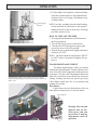
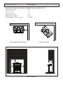
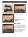
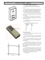
Installation & Operating Manual
The Harman Conquest Gas Stove
Tested to
ANSI Z21.88-2002,
CSA2.33-M02 and
CAN-CGA-2.17-M91
“Ce manuel est disponible en Français sur demande”
R12
SAFETY NOTICE
WARNING: If the information in these instructions
are not followed exactly, a fire or explosion may
result causing property damage, personal injury or
loss of life.
Installation and service must be performed by a qualified installer, service agency, or the gas supplier. Do
not store or use gasoline or other flammable vapors
and liquids in the vicinity of this or any other appliance.
WHAT TO DO IF YOU SMELL GAS
• Do not try to light any appliance.
• Do not touch any electrical switch; do not use any
phone in your building.
• Immediately call your gas supplier from a neighbor’s
phone. Follow the gas supplier’s instructions.
• If you cannot reach your gas supplier, call the fire
department.
save these instructions.
SAFETY NOTICE
Please read this entire manual before you install and use your new room heater. Failure
to follow instructions may result in property damage, bodily injury, or even death.
FOR USE IN THE U.S. AND CANADA. SUITABLE FOR INSTALLATION IN MOBILE HOMES
IF THIS HARMAN STOVE IS NOT PROPERLY INSTALLED, A HOUSE FIRE MAY RESULT. FOR YOUR SAFETY, FOLLOW INSTALLATION DIRECTIONS.
CONTACT LOCAL BUILDING OR FIRE OFFICIALS ABOUT RESTRICTIONS AND INSTALLATION INSPECTION
REQUIREMENTS IN YOUR AREA.
Contact your local authority (such as municipal building department, fire department,
fire prevention bureau, etc.) to determine the need for a permit.
Cette guide d’utilisation est disponible en francais. Chez votre concessionnaire de Harman Stove Company.
CAUTION: Do not operate the appliance with glass removed, cracked or broken. Replacement of the panel(s) should be done by a licensed or qualified service person.
This appliance must be installed in accordance with local codes, if any. If not, follow
the current edition of the National Fuel Gas Code, ANSI Z223.1 or Canadian Installation
Codes, CAN/CGA B149. (Installer l’appareil selon les codes ou règlements locaux, ou, en
l’absence de tels règlements, selon les Codes d’installation CAN/CGA-B149)
Advetissement: Quinconque ne respect
pas à la lettre les instructions dans le
présent manuel risque de déclencher un incendie ou une explosion entraíant des dommages matérials, des lésions corporelles ou
la perte de vies humaines. Installation ou
modification, consulter le manuel des usagers fourn avec ce génerateur d’air chaud.
Ne pas entreposer ni utiliser d’essence ni
d’autres vapeurs ou liquides inflammables
dans le voisinage de cet appareil ou de tout
autre appareil.
POUR VOTRE SÉCURITÉ: Que faire si vous
sentez une odeur de gaz:
• Ne pas tenter d’allumer d’appareil.
• Ne touchez à aucun interrupteur. Ne pas
vous servir des téléphones se trouvant dans
le batiment où vous trouvez.
• Evacuez la pièce, le bâtiment ou la zone.
• Appelez immédiatement votre fournisseur
de gaz depuis un voisin. Suivez les instructions du fournisseur.
• Si vous ne pouvez rejoindre le fournisseur
de gaz, appelez le service dos incendies.
Table of Contents
Introduction
4
Safety Precautions
4
Operation
5
Specifications
8
Clearances
9
Venting
10
Installation
Changing To Natural Gas
Option Installation
Thermostat
Remote Control
Glass Grill
Blower
22
22
26
26
26
27
Maintainence
Wiring Diagram
Parts
28
30
31
Trouble Shooting
33
Warranty 37
Manufactured by The
Harman Stove Company
352 Mountain House Rd.
Halifax PA 17032
USA
Introduction
The Harman Conquest Direct Vent Gas Stove is a
listed gas-fired direct vent room fireplace tested by
Intertek Testing Services/Warnock Hersey to ANSI
Z21.88-2002-CSA 2.33-2002 and CANL/CGA2.17-M91.
The installation of the Conquest Direct Vent
Gas Stove must conform with local codes, or in the
absence of local codes, with National Fuel Gas Code,
ANSI Z223.1 — latest edition and CAN 1 B1-149.1
and .2 Installation Code.
Also for use in mobile (manufactured) homes
after home is sited.
Mobile (manufactured) home installations must
adhere to Title 24 CFR, Part 3280, or CSA Z240.4.
CAUTION: This appliance must be vented to
the outside.
Installation and repair of the Conquest Direct
Vent Gas Stove should be done by a qualified service
person. The appliance should be inspected before
use and at least annually by a qualified service person. More frequent cleaning may be required due to
excessive lint from carpeting, bedding material, etc.
It is imperative that control compartments, burners,
and circulating air passageways of the Conquest be
kept clean.
Due to high temperatures, the Conquest Direct
Vent Gas Stove should be located out of traffic
and away from furniture and draperies.
Children and adults should be alerted to the
hazards of high surface temperatures and
should stay away to avoid burns or clothing
ignition.
Young children should be carefully supervised
when they are in the same room as the
appliance.
Clothing or other flammable materials should
not be placed on or near the appliance.
Surveiller les enfants. Garder les vetements, les
meubles, lessence ou autres liquides a vapeur
inflammables lin de lappareil.
When operating your Harman Conquest Gas
Stove, respect basic safety standards. Read these
instructions carefully before you attempt to operate
the stove. Failure to do so may result in damage to
property or personal injury and may void the product
warranty.
Consult with your local building code agency
and insurance representative before you begin your
installation to ensure compliance with local codes,
including the need for permits and follow-up inspections.
Several issues must be addressed when selecting
a suitable location for your Conquest Gas Stove. Observing required clearances to combustible materials,
the proximity to a safe chimney or venting system
location, and the accessibility of the gas and electrical
supply must all be considered. In addition, selecting a
location that takes advantage of the building’s natural
air flow is also desirable to maximize the heating
effectiveness of the stove. In many cases, this is a
central location within the building.
Any safety screen or guard removed for
servicing an appliance must be replaced prior
to operating the appliance.
This appliance may be installed in an aftermarket permanently located (mobile) home,
where not prohibited by local codes.
This appliance is only for use with the
type(s) of gas indicated on the rating plate. This
appliance is not convertible for use with other
gases, unless a certified kit is used.
Cet appareil peut etre installe dans un maison
prefabriquee (mobile) deja installee a demeure si
les reglements locaux le permettent.
Cet appareil doit etre utilise uniquement
avec les types de gas indiques sur la plaque signaletique. Ne pas l utiliser avec d autres gas sauf
si un kitde conversion dertifie est installe.
OPERATION
WARNING: If you do not follow these instructions exactly, a fire or explosion may result causing property
damage, personal injury, or loss of life.
A. This appliance has a pilot. When lighting the pilot, follow instructions exactly.
B. Before operating, smell all around the appliance area for gas. Be sure to smell next to the floor because some
gas is heavier than air and will settle on the floor.
What to do if you smell gas:
• Do not try to light any gas appliance.
• Do not touch any electric switch.
• Do not use any phone in the building.
• Immediately call your gas supplier from a neighbor’s phone. Follow gas supplier’s instructions.
• If you cannot reach your gas supplier, call the Fire Department.
C. Use only your hand to push in or turn the gas control knob. Never use tools. If the knob will not push in or
turn by hand, don’t try to repair it. Call a qualified service technician. Force or attempted repair may result in
a fire or explosion.
D. Do not use this appliance if any part has been under water. Immediately call a qualified service technician to
inspect the appliance and to replace any part of the control system and gas control that has been under water.
1. STOP! Read the safety information above.
Pilot Flames
2. If using optional thermostat, set thermostat to lowest setting.
3. Turn off electric power to the appliance.
4. Turn ON-OFF/THERMOSTAT switch to “OFF” (center) position.
5. Push in gas control knob slightly and turn clockwise to “OFF”.
NOTE: Knob cannot be turned from “PILOT” to “OFF” unless
knob is pushed in slightly. Do not force.
6. Wait five (5) minutes to clear out any gas. If you then smell gas, STOP!
Follow “B” in the safety information (above) on this label. If you don’t smell gas, go to the next step.
7. Set High-Low Regulator to “HIGH” by turning fully counterclockwise.
8. Press in the gas control knob slightly and turn it counterclockwise to “PILOT.”
9. Find the pilot by looking in front of the rear log, 4 inches right of center.
10. Push the control knob fully down and hold. Immediately push the red piezo igniter button to light the pilot.
It is normal to have to push the red button several times before the pilot ignites. Continue to hold the control
knob in for about one (1) minute after the pilot is lit. Release knob and it will pop back up. Pilot should
remain lit. If it goes out, repeat steps 5 through 9.
•If knob does not pop up when released, stop and immediately call your service technician or gas supplier.
•If the pilot will not stay lit after several tries, turn the gas control knob to “OFF” and call your service
technician or gas supplier.
11. Turn the gas control knob counterclockwise to “ON.”
12. Place the ON-OFF/THERMOSTAT switch to “ON” (up) position or “THERMOSTAT“ (down) position if
the optional thermostat is used.
13. Turn on electric power to appliance.
14. Set the optional thermostat to desired room temperature.
15. Set the High-Low Regulator to desired setting by turning fully counterclockwise for High and fully
clockwise for Low.
OPERATION
Operation
Piezo Ignitor
Button
High-Low
Gas Control
PILOT
HOW TO LIGHT THE FIRE
1. STOP! Read the safety information on the
front cover of this manual.
2. If using the optional thermostat, set thermostat
to the lowest setting.
3. Turn off electric power to the optional blower.
4. Turn the ON-OFF switch to the OFF position.
5. Push in the gas control knob slightly and turn
it clockwise to “OFF.” NOTE: THE KNOB
CANNOT BE TURNED FROM “PILOT” TO
“OFF” UNLESS IT IS PUSHED IN SLIGHTLY. DO NOT FORCE IT.
6. Wait five (5) minutes to clear out any gas. If
you then smell gas, STOP! Follow the safety
information on the front cover. If you don’t
smell gas, go to the next step.
7. Set the High-Low Regulator to High by turning
it fully counterclockwise.
8. Press in the gas control knob slightly and turn
counterclockwise to “PILOT.”
9. Find the pilot by looking down between the
logs as shown at lower left.
10. Push the control knob fully down and hold.
Immediately push the red piezo ignitor button
to light the pilot. It is normal to have to push the
red button several times before the pilot ignites.
Continue to hold the control knob in for about
one (1) minute after the pilot is lit. Release
the knob and it will pop back up. Pilot should
remain lit. If it goes out, repeat steps 5 through
10.
•If the knob does not pop up when released, stop and immediately call your service
technician or gas supplier.
•If the pilot will not stay lit after several
tries, turn the gas control knob to “OFF” and
call your service technician or gas supplier.
11. Turn the gas control knob counterclockwise to
“ON.”
12. Place the ON-OFF switch in the ON position
or turn up the thermostat setting if the optional
thermostat is used.
13. Turn on the electric power to the optional
blower if installed.
14. Set the optional thermostat to the desired room
temperature.
OPERATION
15. Set the High-Low Regulator to desired setting:
Turn fully counterclockwise for High and fully
clockwise for Low. If using a Thermostat, keep
on High setting.
Flame Height
Adjuster
NOTE: An odor, resulting from the initial heating
of new materials in your heater, is not unusual
during the first fire, and in most cases will disappear after an hour or two.
HOW TO TURN OFF THE FIRE
1. If using optional thermostat, set thermostat to
the lowest position.
2. Turn off the electric power to the blower.
3. Turn the ON-OFF switch on the upper right
rear of the stove to the OFF position.
4. Push in the gas control knob slightly and turn it
clockwise to “OFF.”
NOTE: The knob cannot be turned from “PILOT”
to “OFF” unless it is pushed in slightly. Do not
force it.
Normal Flame pattern. Note: Flames will vary in height
and position depending on the placement and the amount of
ember wool.
FLAME HEIGHT ADJUSTMENT
The flame height adjuster can be accessed by
opening the right side panel. Turn the adjuster clockwise to increase flame height and counterclockwise
to decrease. See above left. Adjusting the flames too
high will cause them to have black tips and cause
sooting. Sooting can cause the glass to get dirty.
Check flame height after five to ten minutes and
readjust if necessary.
Pilot Flames
If pilot flames are less than shown at left, use
pilot adjuster shown below, to increase flames.
Pilot Adjuster
Warning: The unit and
adjuster may be hot.
Wear gloves and arm
protection if making
adjustments while in
operation.
VENTING
Only For Qualified Installers
14.102
32.094
29.396
24.974
RATINGS
Input Rating (Btu/hr)(0-4500 ft.)(0-1375 m) Natural
29000
29000
14900
14100
37 3.8/.95
11.0/2.75
1.1/.27
2.8/.7
5.0/1.25
11.5/2.87
21375
21854
Min. Input Rating (Btu/hr)(0-4500 ft.)(0-1375 m)
Orifices (DMS)(0-4500 ft.)(0-1375 m)
Manifold Pressure (in w.c./kPa)
Min. Manifold Pressure (in w.c./kPa)
Min. Inlet Pressure (in w.c./kPa)
Propane
Max. Output (Btu/hr)(0-4500 ft.)(0-1375 m) (Blower Off)
53
VENTING
Only For Qualified Installers
MINIMUM CLEARANCES FROM COMBUSTIBLE CONSTRUCTION
Unit to corner walls2 in.
Unit to side wall
8 in.
Unit to back wall
3 in.
Unit to alcove ceiling16 in.
Maximum alcove depth16 in.
Electrical Rating: 120 Volts, 60 Hz, < 0.7 AMP
2”
3”
8”
2”
Corner Clearances
Side And Back Wall Clearances
16”
8”
16”
8”
Alcove Clearances
VENTING
10
Only For Qualified Installers
Burn Only the Fuel for which the Heater is
Equipped
Natural Gas:
Maximum inlet pressure 7.0” w.c. (1.74 kPa)
The Conquest can burn either natural gas or pro- Minimum inlet pressure 5.0” w.c. (1.25 kPa)
pane, but requires a change-over kit for natural gas. The Gas manifold pressure 3.8” w.c. (0.87 kPa)
label on the burner system module indicates the fuel for
which it is equipped. A second label, (on the valve) also
indicates the fuel type.
NATURAL GAS
PROPANE
Making The Connection
The gas inlet is located on the bottom right side of
the stove. The inlet fitting is a 1/2” male flare fitting.
A separate gas shut-off valve and a 1/8” N.P.T.
plugged tapping should be installed immediately upstream
of the connection to the appliance.
The Conquest Direct Vent Gas Heater must be disconnected from the gas supply piping during any pressure
testing of that system at pressures in excess of 1/2 psig
(3.5 kPa).
The Conquest gas control valve must be in the OFF
position during any pressure testing of the gas supply system at pressures equal to or less than 1/2 psig (3.5 kPa).
WARNING: To avoid pipe compounds from
entering into the gas train, apply compounds only
to male pipe threads and do not apply compound
to the first two threads.
CAUTION: TEST ALL JOINTS FOR LEAKS
BEFORE OPERATING.
Gas Pressure Requirements:
Correct gas pressure and the use of a properly sized
gas supply line are essential for the safe and efficient
performance of this appliance. Make sure that the plumber
or gas supplier checks the gas supply line and gas pressure at installation.
NOTE: Improper gas pressure can affect heater
performance, flame color, or cause pilot outage.
WARNING: This product must be installed by a
licensed plumber or gas fitter when installed within the
Commonwealth of Massachusetts.
LP Gas(Propane):
Maximum inlet pressure 13” w.c. (3.24 kPa)
Minimum inlet pressure 11.5” w.c. (2.74 kPa)
Gas manifold pressure 11” w.c. (2.49 kPa)
Do not use this heater if any part has been under
water or exposed to moisture corrosion. Immediately
call a qualified service technician to inspect the heater
and replace any part of the control system and any
gas control which has been under water.
Ne pas se servir de cet appareil s’il a étre plongé dans
l’eau, complètement ou en partie. Appeler un technicien
qualifié pour inspecter l’appareil et remplacer toute partie
du système de contrôle et toute commande qui ont été
plongés dans l’au.
If appliance is installed directly on carpeting,
tile, or other combustible material other than wood
flooring, the appliance shall be installed on a metal
or wood panel extending the full width and depth of
the appliance.
Keep areas around air openings into the combustion chamber free of obstructions, and do not block
any panels where access is needed for servicing.
RECOMMENDED GAS PIPE DIAMETER
Pipe Length (Feet)
Schedule 40 Pipe
Inside Diameter
Tubing, Type L
Outside Diameter
N.G.
N.G.
L.P.
L.P.
0-101/2”
3/8”1/2”
3/8”
1.3 cm1.0 cm1.3 cm1.0 cm
10-40
1/2”
1/2”
5/8”
1/2”
1.3 cm1.3 cm1.6 cm1.3 cm
40-1001/2”1/2”
3/4”1/2”
1.3 cm1.3 cm1.6 cm1.3 cm
100-150
3/4”
1/2”
7/8”
3/4”
2.0 cm1.3 cm2.3 cm2.0 cm
NOTE: NEVER USE PLASTIC PIPE. CHECK TO CONFIRM WHETHER YOUR LOCAL CODES ALLOW COPPER
TUBING OR GALVANIZED PIPE.
A LABEL ON THE BURNER SYSTEM
MODULE STATES THE FUEL FOR
WHICH THE HEATER IS EQUIPPED.
Only For Qualified Installers
VENTING
11
Use Only Approved Venting
This appliance has been tested and is listed for installation with Simpson Duravent GS venting components. The Simpson Duravent GS warranty will be voided, and serious fire, health, or other safety hazards
may result from any of the following actions:
• Installation of any damaged Duravent GS component.
• Unauthorized modification of the Duravent GS System.
• Installation of any component part not manufactured or approved by Simpson Duravent.
• Installation other than as instructed by Simpson Duravent and the appliance manufacturer.
Consult your local building codes before beginning the installation, and follow the manufacturer’s
instructions exactly. The Simpson Duravent GS venting components listed below are approved for use with
the Conquest Direct Vent Gas Stove.
Part Numbers for SimpsonDura-Vent Pipe and Fittings
6-5/8 x 4
8” x 5”
Description
n/a1208
6” Pipe Length
908B1208B
6” Pipe Length, Black
n/a1207
9” Pipe Length
907B1207B
9” Pipe Length, Black
906120612” Pipe Length
906B1206B12” Pipe Length, Black
904120424” Pipe Length
904B1204B24” Pipe Length, Black
9031203
36” Pipe Length
903B1203B
36” Pipe Length, Black
9021202
48” Pipe Length
902B1202B
48” Pipe Length, Black
n/a
1211
11” to 14-5/8” Pipe, Adjustable
911B
1211B
11” to 14-5/8” Pipe, Adjustable, Black
n/a121717” to 24” Pipe, Adjustable
945
1245
45o Elbow
945B
1245B
45o Elbow, Black
9901290
90o Elbow
990B1290B
90o Elbow, Black
9401240
Rnd Support Box/Wall Thimble Cover
9411241
Cathedral Ceiling Support Box
9431243
Flashing, 0/12 to 6/12 Roof Pitch
943S1243S
Flashing, 7/12 to 12/12 Roof Pitch
953
1253
Storm Collar
9631263
Ceiling Firestop
9881288
Wall Strap
9811281
Snorkel Termination (36”)
9821282
Snorkel Termination (14”)
984
1284
Horizontal Square Termination
9801280
Vertical Termination
9911291
Vertical Termination, High Wind
950
1250
Vinyl Siding Standoff
1222D (Only available from Harman)
8” x 5” to 6 5/8” x 4” Adaptor
VENTING
12
Only For Qualified Installers
Selkirk Direct-Temp Vs. Simpson Dura-Vent Direct Vent GS
Selkirk Direct-Temp
Stock No. Description
4DT-6
6” Pipe Length, Galvanized
4DT-6B 6” Pipe Length, Black
4DT-9
9” Pipe Length, Galvanized
4DT-9B 9” Pipe Length, Black
4DT-12
12” Pipe Length, Galvanized
4DT-12B12” Pipe Length, Black
4DT-18
18” Pipe Length, Galvanized
4DT-18B18” Pipe Length, Black
4DT-24
24” Pipe Length, Galvanized
4DT-24B24” Pipe Length, Black
4DT-36
36” Pipe Length, Galvanized
4DT-36B
36” Pipe Length, Black
4DT-48
48” Pipe Length, Galvanized
4DT-48B
48” Pipe Length, Black
4DT-AJ
Adjustable Length, 11” - 14”, Galv.
4DT-AJB
Adjustable Length, 11” - 14”, Black
4DT-EL45
45o Elbow, Galvanized
4DT-EL45B 45o Elbow, Black
4DT-EL90
90o Elbow, Galvanized
4DT-EL90B 90o Elbow, Black
4DT-AA
Appliance Adaptor, Black
4DT-RD
Restriction Disc
4DT-CS
Ceiling Support
4DT-CSS Cathedral Support Box
4DT-WS/B
Wall Support Band
4DT-OS
Offset Support
4DT-WT
Round Wall Thimble, Black
4DT-FS Firestop Spacer
4DT-TP
Trim Plate, Black
4DT-HKA
Horizontal Term. Kit A
4DT-HKB
Horizontal Term. Kit B
4DT-VKC
Vertical Termination Kit
4DT-HVC
High Wind Vertical Cap
4DT-HHC
High Wind Horizontal Cap
4DT-SC
Storm Collar
4DT-AF6
Adjustable Flashing, 0/12-6/12
4DT-AF12
Adjustable Flashing 6/12-12/12
4DT-VS
Vinyl Siding Standoff
4DT-VSP
Vinyl Siding Shield Plate
4DT-ST14
Snorkel Termination 14”
4DT-ST36
Snorkel Termination 36”
Simpson Dura-Vent Direct Vent GS
Stock No. Description
908
6” Pipe Length, Galvanized
908B
6” Pipe Length, Black
907
9” Pipe Length, Galvanized
907B
9” Pipe Length, Black
906
12” Pipe Length, Galvanized
906B12” Pipe Length, Black
n/a
n/a
904
24” Pipe Length, Galvanized
904B24” Pipe Length, Black
903
36” Pipe Length, Galvanized
903B
36” Pipe Length, Black
902
48” Pipe Length, Galvanized
902B
48” Pipe Length, Black
911
Adjustable Length, 11”-14”, Galv.
911B
Adjustable Length, 11”-14”, Black
945
45o Elbow, Galvanized
945B
45o Elbow, Black
990
90o Elbow, Galvanized
990B
90o Elbow, Black
n/a
929
Restrictor Disc
949
Round Ceiling Spt/Wall Thimble Cvr
941
Cathedral Ceiling Support Box
988
Wall Strap
989
Elbow Strap
942
Wall Thimble
963
Ceiling Firestop
n/a
970
Basic Horizontal Term. Kit
971
Horizontal Termination Kit A
978
Vertical Termination Kit
991
High Wind Termination Cap
985
Horizontal Square High Wind Termination
953
Storm Collar
943
Adjustable Flashing, 0/12-6/12
943S
Adjustable Flashing 6/12-12/12
950
Vinyl Siding Standoff
n/a
982
Snorkel Termination Cap 14”
981
Snorkel Termination Cap 36”
VENTING
Only For Qualified Installers
Secure Vent Direct Vent System - 4” x 6-5/8” and 5” x 8”
Description
Secure
Vent
Cat No.
Simpson Dura-Vent
Direct Vent GS
Stock No.
13
Cross Reference List
Secure
Vent
Cat No.
Simpson Dura-Vent
Direct Vent GS
Stock No.
Length 6” (Galvalume).........................SV4L6
Length 6” (Black)................................SV4LB6
Length 12” (Galvalume).......................SV4L12
Length 12” (Black)..............................SV4LB12
Length 24” (Galvalume).......................SV4L24
Length 24” (Black)..............................SV4LB24
Length 36” (Galvalume).......................SV4L36
Length 36” (Black)..............................SV4LB36
Length 48” (Galvalume).......................SV4L48
Length 48” (Black)..............................SV4LB48
Adj. Length (Galv.)(Adjustable 6”).........SV4LA
Adj. Length (Blk)(Adjustable 6”)...........SV4LBA
Adj. Length (Galv.)(Adjustable 12”).......SV4LA12
Adj. Length (Blk)(Adjustable 12”).........SV4LBA12
Adj. Length (Galv.)(Adjustable 24”).......SV4LA24
Adj. Length (Blk)(Adjustable 24”)..........SV4LBA24
908
908B
906
906B
904
904B
903
903B
902
902B
n/a
n/a
n/a
n/a
917
917B
SV5L6
SV5LB6
SV5L12
SV5LB12
SV5L24
SV5LB24
SV5L36
SV5LB36
SV5L48
SV5LB48
SV5LA
SV5LBA
SV5LA12
SV5LBA12
SV5LA24
SV5LBA24
1208
1208B
1206
1206B
1204
1204B
1203
1203B
1202
1202B
n/a
n/a
n/a
n/a
1217
1217B
Swivel 45o elbow (Galvalume)...............SV4E45
Swivel 45o elbow (Black).....................SV4EB45
Rigid 45o elbow (Black).......................SV4EBR45
Swivel 90o elbow (Galvalume)..............SV4E90
Swivel 90o elbow (Black).....................SV4EB90
Rigid 90o elbow (Black).......................SV4EBR90
945G
945BG
945B
990G
990BG
990B
SV5E45
SV5EB45
SV5EBR45
SV5E90
SV5EB90
SV5EBR90
1245G
1245BG
1245B
1290G
1290BG
1290B
Adjustable Decorative
Square Cathedral Support...................SV4CSB
Collar for the Decorative
Square Cathedral Support....................SV4AC
Decorative Black Plate (square)...........SV4PF
Universal Support...............................SV4SU
Floor Support.....................................SV4SD
Roof Brace.........................................SV4BS
Roof Support......................................SV4ST
941
SV5CSB
1241
n/a
940
989
n/a
n/a
n/a
SV5AC
SV5PF
SV5SU
SV5SD
SV5BS
SV5ST
n/a
1240
1289
n/a
n/a
n/a
Wall Band..........................................SV4BM
Attic Radiation Shield..........................SV4RSA
Wall Radiation Shield..........................SV4RSM
Firestop..............................................SV4BF
988
n/a
942
963
SV5BM
SV5RSA
SV5RSM
SV5BF
1288
n/a
1242
1263
Flat Roof Flashing(storm collar incl.)....SV4F
Adjustable Roof Flashing
1/12 - 7/12 (storm collar incl.)..............SV4FA
Adjustable Roof Flashing
8/12 - 12/12 (storm collar incl.)............SV4FB
Storm Collar.......................................SV4FC
943F
SV5F
1243F
943
SV5FA
1243
943S
953
SV5F B
SV5FC
1243S
1253
Vinyl Shield Protector.........................SV4VS
Restrictor Disk...................................SV4RD
VERTICAL TERMINATION CAP...........SV4CGV
HORIZONTAL TERMINATION CAP.......SV4CHC-1
SNORKEL CAP 14”...........................SV4STC14
SNORKEL CAP 36”...........................SV4STC36
950
929
980
984
982
981
SV5VS
SV5RD
SV5CGV
SV5CHC-1
SV5STC14
SV5STC36
1250
n/a
1280
1284
1282
1281
14
VENTING
Montigo Direct Vent
Only For Qualified Installers
Standard Series Direct Vent (4”/ 7”)
Description
Order Code
Horizontal Terminations
3” length, no mounting frame (use with MSR or MOSR) .................... MTO3
3” Termination, with integral mounting frame .................................... MTO3F
Vertical Termination
Termination for vertical installations ..................................................MVTK1
Includes MXT-10 adaptor (for straight, vertical installations)
Termination Touch-Up Paint ............................................................Paint03
Vent Pipes
Extensions
18” rigid section (female/female) ..................................................... EXT18
12” rigid section (female/male) ........................................................MEXT1
24” rigid section (female/male) ........................................................MEXT2
36” rigid section (female/male) ........................................................MEXT3
48” rigid section (female/male) ........................................................MEXT4
72” rigid section (female/male) ........................................................MEXT6
Flex Sections
12” flex section (female/female connectors) .....................................MFL1
18” flex section (female/female) ......................................................MFL18
24” flex section (female/female) ..................................................... MFL2
36” flex section (female/female) ......................................................MFL3
48” flex section (female/female) ......................................................MFL4
Elbows
45° solid elbow section.(female/male connectors) .............................EEL45
90° elbow (female/female) ..............................................................MEL90F/F
90° elbow (male/male). ..................................................................MEL90M/M
90° elbow (female/male). ...............................................................MEL90F/M
Clearance Reducing Sleeve ............................................................CRS30
Vertical Installation Adaptor
10” flue adaptor for straight, vertical installations (female/female) ........ MXT10
Vent Connector
4” vent connector (male/male) ........................................................ MVA
Termination Frames
Siding or Stucco Frame ..............................................................MSR
Used for easy installation of termination.
Siding or Stucco Can ..................................................................MOSR
Used to provide installation of termination from the inside of the building.
Brick Siding Can
Used for installation of termination on brick wall.
4” depth ........................................................................................BSR-4
6” depth ........................................................................................BSR-6
Only For Qualified Installers
VENTING
Montigo Direct Vent
15
Standard Series Direct Vent (4”/ 7”)
Description
Order Code
Snorkel Terminations
18” vertical rise .............................................................................. SNK47-2
30” vertical rise ...............................................................................SNK47-3
Heat Guard
Fits all Standard Series (4/7”) terminations ........................................MTKOG
Heat Shields
Through-the-wall Radiation Shield for 4”/7” venting .......................RHS100
Vinyl Siding Shield Recommended for protecting vinyl siding ........... RHS105
(above was Discontinued Replace with VSS)
Vinyl Siding Shield Recommended for protecting vinyl siding ............VSS
Vertical Installation Accessories
7” Firestop .....................................................................................FS7
7” Support plate & support ring ........................................................MSPXT7
7” Support plate & support ring (Bulk pack of 6) ................................MSP706
Flashing and storm collar for 1/12 to 7/12 pitch roof .......................... MRF7
Flashing and storm collar for 1/12 to 7/12 pitch roof (Bulk pack of 6) ....MRF706
Flashing and storm collar for 7/12 to 12/12 pitch roof ..........................MRF-12
Flashing and storm collar for 7/12 to 12/12 pitch roof (Bulk pack of 6) ..MRF1206
Horizontal Vent Restrictors
For 8’ - 14’ horizontal vent run ...........................................................MHVR8
For 15’ - 24” horizontal vent run ........................................................MHVR15
For 25’ - 35’ horitontal vent run ......................................................... MHVR25
Vent restrictors may not be required. Contact the factory for more information.
Vertical Vent Restrictors
For 8’ - 14’ vertical vent run ...............................................................MVVR8
For 15’ - 24” vertical vent run .............................................................MVVR15
For 25’ or greater vertical vent run ......................................................MVVR25
Vent restrictors may not be required. Contact the factory for more information.
Mobile Home Kits
Wall Penetration Kit (For 2 x 4 Construction) ....................................WPKMH4
Kit includes wall shield and 4” termination. Suitable for all
corner installations & straight through the wall installations
with 2 x 4 construction.
Wall Penetration Kit (For 2 x 6 Construction) ....................................WPKMH6
Kit includes wall shield and 5” termination.
16
VENTING
Montigo Direct Vent
Only For Qualified Installers
Premium Series Direct Vent (5”/8”)
Description
Order Code
Horizontal Terminations
3” Termination with no mounting frame (male connector). ..................... PTO3
(use with MSR or MOSR).
3” Termination & mounting frame (male connector). ............................. PTO3F
Vertical Termination
Termination for vertical installations (male connector) ........................... PVTK1
Includes PXT-10 adaptor (for straight, vertical installations).
Vent Pipes
Note: For all Rear Vent applications with no vertical rise, there is a maximum
horizontal run of 20”.
Extensions
5” rigid section (female/female connectors) .......................................... PXT5
10” rigid section (female/female) ......................................................... PXT10 .
20” rigid section (female/female) ......................................................... PXT20
12” rigid section (female/male connectors) .......................................... PEXT1
24” rigid section (female/male) ........................................................... PEXT2
36” rigid section (female/male)............................................................ PEXT3
48” rigid section (female/mal............................................................... PEXT4
72” rigid section (female/male) ........................................................... PEXT6
Flex Sections
12” flex section (female/female connectors) ........................................ PFL1
18” flex section (female/female........................................................... PFL18
24” flex section (female/female) ......................................................... PFL2
36” flex section (female/female) ......................................................... PFL3
48” flex section (female/female) ......................................................... PFL4
Elbows
45° elbow (female/male connectors) .................................................. PEL45FM
90° elbow (female/female connectors) ................................................PEL90F/F
90° elbow (male/male) ......................................................................PEL90M/M
90° elbow (female/male) ...................................................................PEL90F/M
Clearance Reducing Sleeve ...............................................................CRS30
Vent Connector
4” length vent connector (male/male connectors) ................................. PVA
Vertical Vent Reducer
10” length, reduces vertical 5”/8” venting to 4”/7” (male/female connectors) PVA5487
Termination Frames
Siding or Stucco Frame ..................................................................MSR
Used for easy installation of termination.
Siding or Stucco Can ......................................................................MOSR
Used to provide installation of termination from the inside of the building.
Brick Siding Can
Used for installation of termination on brick wall.
4” depth ............................................................................................ BSR-4
6” depth .............................................................................................BSR-6
Only For Qualified Installers
VENTING
Montigo Direct Vent
17
Premium Series Direct Vent (5”/8”)
Description
Order Code
Snorkel Terminations
18” vertical rise ......................................................................................SNK58-2
30” vertical rise ......................................................................................SNK58-3
Insulated Offset Box
M38DV-ST offset box. Used only on the M38DV-ST when a shelf or
T.V. stand is required above the fireplace. ................................................ DVSTCNT
Heat Guard
Fits all Premium Series (5”/8” dia.) terminations .......................................PTKOG
Heat Shields
Through-the-wall Radiation Shield for 5”/8” venting ...............................RHS101
Vinyl Siding Shield Recommended for protecting vinyl siding ...................RHS105
Discontinued Replace with VSS
Vinyl Siding Shield Recommended for protecting vinyl siding .................. VSS
Vertical Installation Accessories
8” Firestop ............................................................................................PS8
8” Support plate & support ring ................................................................PSPXT-8
8” Support plate & support ring (Bulk pack of 6) ........................................PSP806
Flashing and storm collar for 1/12 to 7/12 pitch roof ..................................PRF7
Flashing and storm collar for 1/12 to 7/12 pitch roof (Bulk pack of 6) ...........PRF706
Flashing and storm collar for 7/12 to 12/12 pitch roof .................................PRF12
Flashing and storm collar for 7/12 to 12/12 pitch roof (Bulk pack of 6) .........PRF1206
Horizontal Vent Restrictors
For 8’ - 14’ horizontal vent run ................................................................. PHVR8
For 15’ - 24” horizontal vent run ...............................................................PHVR15
For 25’ - 35’ horitontal vent run .................................................................PHVR25
Vent restrictors may not be required. Contact the factory for more information.
Vertical Vent Restrictors
For 8’ - 14’ vertical vent run ......................................................................PVVR8
For 15’ - 24” vertical vent run ....................................................................PVVR15
For 25’ or greater vertical vent run .............................................................PVVR25
Vent restrictors may not be required. Contact the factory for more information.
VENTING
18
Only For Qualified Installers
EXCELDirect - Component List
Liste des composants
Longueurs
Longueur 6’’, Galvalume
Longueur 6’’, Noire
Longueur 12’’, Galvalume
Long����������������
ueur 12’’, Noire
Longueur 24’’, Galvalume
Longueur 24’’, Noire
Longueur 48’’, Galvalume
Longueur 48’’, Noire
Longueur flexible 36’’
Longueur télescopique 12’’, Galvalume
Longueur télescopique 12’’, Noire
Coudes
Coude 45º, Galvalume
Coude 45º, Noir
Coude 90º, Galvalume
Coude 9��������
0º, Noir
Supports et coupe-feux
Support carré / Coupe-feu radiant *
Support rond / Coupe-feu radiant **
Support pour plafond / Coupe-feu
Support de déviation
Support de toit
Support mural ajustable
Coupe-feu mural ajustable
Anneau de finition, noir
Coupe-feu radiant d’entretoit
Chapeaux
Chapeau horizontal
Chapeau horizontal de luxe
Chapeau vertical
Chapeau périscope 14”
Chapeau périscope 36”
Solins et collets
Solin plat
Solin ajustable 1/12 – 7/12
Solin ajustable 8/12 – 12/12
Solin pour cheminée de maçonnerie
Collet de solin
Accessoires
Disque restricteur
Protecteur de vinyl
Adaptateur pour appareil de coaxial à colinéaire
Adaptateur pour chapeau de colinéaire à coaxial
Raccord de gaine flexible 3’’
Adaptateur de cheminée 6’’ – Type A et maçonnerie ***
Adaptateur de cheminée 7” – Type A ***
Adaptateur de cheminée 8” – Type A ***
*:
Component Name
Lengths
6” Length, Galvalume
6” Length, Black
12” Length, Galvalume
12” Length, Black
24” Length, Galvalume
24” Length, Black
48” Length, Galvalume
48” Length, Black
Flexible Length, 36”
12” Adjustable Length, Galvalume
12” Adjustable Length, Black
Elbows
45º, Elbow, Galvalume
45º, Elbow, Black
90º, Elbow, Galvalume
90º, Elbow, Black
Supports & Firestops
Square Support / Radiation Shield *
Round Support / Radiation Shield **
Ceiling Support / Firestop
Offset Support
Roof Support
Adjustable Wall Support
Adjustable Wall Thimble
Trim Ring, Black
Attic Radiation Shield / Firestop
Terminations
Horizontal Termination
Deluxe Horizontal Termination
Vertical Termination
14” Snorkel Termination
36” Snorkel Termination
Flashing and collar
Flat Flashing
Adjustable Flashing 1/12 – 7/12
Adjustable Flashing 8/12 – 12/12
Masonry Chimney Flashing
Storm collar
Accessories
Restrictor Disk
Vinyl Siding Standoff
Coaxial to Collinear Appliance Adapter
Collinear to Coaxial Termination Adapter
Flex Liner Connector 3’’
Type A / Masonry Chimney Adapter 6” ***
Type A Chimney Adapter – 7” ***
Type A Chimney Adapter – 8” ***
Ø4” I.D
Ø5” I.D.
Ø 6 5/8” O.D
Ø8” O.D
TC-4DL6
TC-4DL6B
TC-4DL1
TC-4DL1B
TC-4DL2
TC-4DL2B
TC-4DL4
TC-4DL4B
TC-4DLF
TC-4DLT
TC-4DLTB
TC-5DL6
TC-5DL6B
TC-5DL1
TC-5DL1B
TC-5DL2
TC-5DL2B
TC-5DL4
TC-5DL4B
TC-5DLF
TC-5DLT
TC-5DLTB
TE-4DE45
TE-4DE45B
TE-4DE90
TE-4DE90B
TE-5DE45
TE-5DE45B
TE-5DE90
TE-5DE90B
TM-4SS
TM-4RDS
TM-4CS
TM-5SS
TM-5RDS
TM-5CS
TM-OS
TM-SR
TM-WS
TM-4WT
TM-5WT
TM-4TR
TM-5TR
TM-4AS
TM-5AS
TM-4HT
TM-4DHT
TM-4VT
TM-4ST14
TM-4ST36
TF-4F
TF-4FA
TF-4FB
TF-4MF
TM-4RD
XF-6EF
XF-6EFA
XF-6EFB
--TM-SC
--TM-VSS
TM-4CAA
--TM-4CTA
--TM-CFAA3
TM-4CA6
--TM-4CA7
--TM-4CA8
---
Order the Excel Chimney Square Support Extension (6ESSE for 4” Ø ; 7ESSE for 5” Ø) if required.
**: Order the Excel Chimney Round Support Extension (6ERDSE for 4” Ø ; 7ERDSE for 5” Ø) if required.
***: These components are not UL or Warnock Hersey listed.
TM-5HT
TM-5DHT
TM-5VT
TM-5ST14
TM-5ST36
Only For Qualified Installers
This appliance must not be
connected to a chimney flue serving
a separate solid fuel burning
appliance.
Venting terminals shall not be recessed
into a wall or siding.
VENTING
19
Venting with 6 5/8” x 4” Pipe
Maximum of four 450 elbows allowed.
Subtract three feet of total horizontal pipe
length for each of the 3rd and 4th 450 elbows
used.
Maximum of two 900 elbows allowed.
Subtract five feet of total horizontal pipe
length for second elbow.
A combination of one 900 elbow and two 450
elbows is allowed.
Subtract three feet of total horizontal pipe
length for each 450 elbow used.
Rear Vent
A snorkel termination is
recommended when no
vertical pipe is used.
8”
Vent termination must remain within the
shaded area regardless of configuration.
6 5/8” to 8” Increaser
20
VENTING
Only For Qualified Installers
(a) Termination 10 ft. (3 m) or less from ridge, wall, or parapet
(b) Termination more than 10 ft. (3 m) from ridge, wall, or parapet
The following diagram and table detail the restrictions on the vent terminal location.
Only For Qualified Installers
A=
B=
Clearance above grade,
veranda, porch, deck, or balcony
Clearance to window or door
that may be opened
C=
D=
E=
F=
G=
H=
I=
J=
Clearance to permanently
closed window
Vertical clearance to ventilated soffit
located above the terminal within a
horizontal distance of 2 feet (61 cm)
from the center line of the terminal
Clearance to unventilated soffit
Clearance to outside corner
Clearance to inside corner
Clearance to each side of
center line extended above
meter/regulator assembly
Clearance to service regulator
vent outlet
Clearance to nonmechanical
air supply inlet to building or
the combustion air inlet to any
other appliance
K=
L=
M=
Clearance to a mechanical air
supply inlet
Clearance above paved sidewalk
or paved driveway located on
public property
Clearance under veranda, porch
deck, or balcony
VENTING
21
Canadian Installations1
12 Inches (30 cm)
US Installations2
12 inches (30 cm)
6 Inches (15 cm) for appliance < 10,000
Btuh (3 kW), 12 inches (30 cm) for
appliances > 10,000 Btuh (3kW) and <
100,000 Btuh (30 kW), 36 inches (91 cm)
for aplliances > 100,000 Btuh (30 kW)
*
6 Inches (15 cm) for appliance < 10,000
Btuh (3 kW), 9 inches (23 cm) for
appliances > 10,000 Btuh (3kW) and <
50,000 Btuh (15 kW), 12 inches (30 cm)
for aplliances > 50,000 Btuh (15 kW)
*
*
*
*
*
3 feet (91 cm) within a height of 15
feet above the meter/ regulator assembly
*
*
*
*
6 feet (1.83 m)
*
6 inches (15 cm) for appliances < 10,000
Btuh (3 kW), 12 inches (30 cm) for
appliances > 10,000 Btuh (3 kW) and <
100,000 Btuh (30 kW), 36 inches (91 cm)
for appliances > 100,000 Btuh (30 kW)
6 feet (1.83 m)
6 Inches (15 cm) for appliance < 10,000
Btuh (3 kW), 9 inches (23 cm) for
appliances > 10,000 Btuh (3kW) and <
50,000 Btuh (15 kW), 12 inches (30 cm)
for aplliances > 50,000 Btuh (15 kW)
3 feet (91 cm) above if within 10 feet
(3 m) horizontally
*
7 feet (2.13 m) †
12 inches (30 cm) ‡
*
*
1
In accordance with the current CSA-B149. 1 Natural Cas and Propane Installation Code
2
In accordance with the current ANSI Z223.1 / NFPA 54 National Fuel Gas Code
† A vent shall not terminate directly above a sidewalk or paved driveway that is located between two single family dwellings and
serves
both dwellings.
‡ Permitted only if veranda, porch, deck, or balcony is fully open on a minimum of two sides beneath the floor.
* For clearances not specified in ANSI Z223. 1 / NFPA 54 or CSA-B149.1, one of the following shall be indicated:
a) A minimum clearance value determined by testing in accordance with section 2.19.6, or;
b) A reference to the following footnote:
“Clearance in accordance with local installation codes and the requirements of the gas supplier”
«Dégagement conforme aux codes d’installation locaux et aux exigences du foumisseunde gaz»
VENTING
Damper Settings
Top Vent Only
22
Only For Qualified Installers
Vent damper shown in the
Maximum Draft”OPEN” position
for top vent. Note: This would be
the Minimum Draft”CLOSED”
position if a rear vent was
installed.
A vent damper is provided to allow fine tuning
of the draft. Too little draft will cause flames to be too
long with black tips and too much draft will cause
flames to be short and blue.
To adjust the damper, burn the unit on High 10
minutes or more. Adjust the vent damper to a position in the ranges listed below that produces the most
desirable flame pattern.
Range Of Approved Damper Settings
Natural Gas or Propane
0 Feet (rear Vent)
6 feet
12 feet
24 feet
36 feet
Open
1/4 to Open
1/4 to Open
Closed to 1/2
Closed to 1/2
OPEN
O
N
E
H
A
LF
CLOSED
INSTALLATION
Only For Qualified Installers
23
Changing to Natural Gas
Natural Gas Conversion Kit
NG Conversion
Instructions
1
Remove four
bolts and
remove burner
module from
stove.
NG Pilot Orifice
NG Conversion label
NG Orifice #37
NG Valve
Conversion
Module
2
Use a 1/2” deep well
socket to remove the LP
#53 orifice and replace
with the #37 Natural gas
orifice from the kit.
Natural Gas Kit
Part No. 1-00-09112
This kit is only for use in the Conquest direct
vent gas stove.
3
Remove pilot tower
with a 7/16” wrench.
Replace LP orifice with
Natural Gas orifice. See
instructions in kit.
4
Remove the three screws that hold the
LP knob module in place. Remove the
module and replace with the Natural
gas module from the kit. See kit
instructions.
24
INSTALLATION
Only For Qualified Installers
5
Reinstall burner module back into the
stove with the four bolts that were
removed. Check gasket for damage
and replace if necessary. Check for gas
leaks when finished.
Note: The higher the orifice number the smaller
hole in the tip. For example, a number 52 orifice
has a larger hole than a number 60 orifice.
6
Place conversion sticker (provided in Kit) on the valve. This
is to permanently mark the valve that it has been converted
to Natural Gas. This label is important in the event that the
valve is ever removed and mixed in with other valves.
7
Mark the proper box on the
label with a permanent marker.
Note: If no conversion is made,
the box for propane must still be
marked by the installer.
NATURAL GAS
PROPANE
9
Verify gas inlet and manifold pressures are within the
specifications on the appliance data plate located on the rear
of the unit.
Only For Qualified Installers
INSTALLATION
25
Log Placement
Rear Log
Wool
Nuggets
Front Log
Place the rear log behind the front log with the branch
resting on the front log on the right side as shown.
Andirons
Air Deflector
Before lighting a fire check that the rear
log is as far back against the rear wall as
possible.
The front log should be slid rearward
in it’s position between the andirons and
deflector plate.
Ember Placement
Place the front log as shown between the andirons and the
air deflector.
After the logs are positioned, place the embers
as shown above.
There are two types of embers supplied. One is
a wool like material and the other like a nugget.
The wool is to be placed on the screen by pulling
small pieces from the bunch with your fingers or a
tweezers. Place the wool lightly on the screen over
the horse shoe tube area. Be careful not to compact
the wool. The looser and fluffier the better. The
placement and density of the wool changes the front
flames and glowing embers. You can try different
placement to get the look you prefer.
Place nuggets where desired elsewhere in front
of the log.
26
INSTALLATION - Options
Round Tile Not
Used On Top Vent
Only For Qualified Installers
Tile Kit
Each tile kit contains six tiles and fifteen allenset screws. If the Conquest is installed as a top vent,
then the round tile is not used. If it is installed as a
rear vent, then the trim ring is not used.
Installing Tiles
Below each tile opening are three threaded
holes. In some cases it may be helpful to remove
extra paint from the treads with a 1/4-20 tap.
Trim Ring Not
Used On Rear
Vent.
Allen Set
Screws
1. Screw the set screws down until the top of the
screw is about the thickness of the tile below the
top surface.
2. Place the proper tile in the opening.
3. Observe the level of the tile. If the level of the
tile is not satisfactory, remove the tile by pressing down on one of the corners and adjust set
screws accordingly.
Only For Qualified Installers
INSTALLATION - Options
Connecting the Optional Thermostat
If the optional thermostat is used, it must
be plugged into the TH terminals located on the
valve.
When installing a millivolt control system, use
only a special low resistance thermostat. DO NOT
USE A REGULAR HEATING THERMOSTAT.
Be sure that all electrical connections are clean,
free from corrosion, and tight. Inspect connections
periodically to confirm that no corrosion has built
up over time.
When properly installed and maintained, a
millivolt control system should give many years of
trouble-free service.
It is important to use wire of a gauge proper for
the length of the wire:
Thermostat
Burner Button
Glass Grill
27
RECOMMENDED WIRE GAUGES
Maximum Wire
Length
Gauge
100’14
60’16
40’18
25’
20
15’
22
Remote Control Kit
The button on the remote control can be used
to turn the fire on and off.
This remote uses the ultrasonic control method
and does not need to be pointed directly at the fireplace.
The kit includes installation instructions, a hand
held sending unit, receiving unit, mounting bracket,
and all wiring.
Note: The ON/OFF switch must be “OFF” when
using the remote or a thermostat. If the switch is in
the “ON” position, the fire will stay on even when
the set temperature on the thermostat is reached.
Glass Grill
To install the glass grill remove the door and
slide the top of the vertical bars up into the slots at
the top of the firebox opening. Lower the grill down
so the bottom of the vertical bars rest just inside the
lip at the bottom of the firebox opening.
Reinstall door.
28
INSTALLATION - Options
Optional Blower
Only For Qualified Installers
The Blower Kit (Part # 1-00-09102) includes a
blower assembly ready to bolt to the left side of the
stove and a blower chamber cover.
The blower has a variable speed control knob to
adjust the blower speed as desired. A special switch
is used to automatically start the blower when the
stove temperature is hot enough to blow warm air.
This switch will also stop the blower when the stove
temperature drops below the point that warm air is
available.
Power Cord
Blower Assembly
Speed Control Knob
Installation
1. Open the left side panel.
2. Remove the four screws from the left side of the
firebox with a 5/16” socket.
3. Place the blower as shown and start the top
screw. This will hold the blower in place and
make it easier to install the other three screws.
4. Route the power cord rearward between the side
panel and the pedestal and plug into a 120 volt
outlet.
5. Open the right side panel and remove the two
screws on the right side of the firebox.
6. Use the two screws to fasten the blower chamber cover plate to the firebox. This plate prevents air from the blower from escaping the air
chamber.
7. Close side panels.
Operation
Turn the speed control knob clockwise until it
clicks. This is the full speed position. Turning the
knob farther in the clockwise direction will gradually
reduce the blower speed. To turn the blower “OFF”
turn the knob counterclockwise until it clicks.
Blower Chamber Cover
This blower is equipped with a three-prong
(grounding) plug for protection against shock
hazard and should be plugged directly into a
properly grounded three-prong receptacle.
Do not cut or remove the grounding prong
from the plug.
MAINTENANCE
A qualified service person should conduct an
annual inspection and maintenance of your Conquest,
its venting, and the installation to keep it running
safely and efficiently. The following procedures
should be performed only by a qualified service person. The gas supply should be turned off whenever
a maintenance procedure is performed.
If the glass door or side doors are removed for
servicing, they must be replaced prior to operating
the stove.
Latch
Air Grill
CAUTION: Do not operate this appliance
with the glass front removed, cracked, or
broken. Replacement of glass should be done
by a licensed or qualified service person.
Never use substitute materials.
CAUTIONNER: N’opère l’appareil
avec le verre enlève, craque ou casse. Le
remplacement du panneau(s) devrait être
fait par une personne de service qualifiá ou
autorisá.
Removing the Glass Front
Remove the air grill by pulling forward.
Lift the latch shown above and tilt the glass door
out at the top and lift off the hooks at the bottom.
Handle the glass with care.
Door
Gold Frame
29
Top
Clip
Glass
Bottom
Clip
Gasket
DO NOT STRIKE OR SLAM GLASS
Replacing the Gasket
The Conquest uses part no. 3-44-00539 fiberglass gasket in the front door. Should it ever need
replacement, use only the proper replacement gasket
that is available from your Harman dealer. Replace
the gasket as follows:
1. Lay glass door face down on a soft surface that
will not scratch the glass.
2. Remove the nuts holding the top and bottom
glass clip in place.
3. Remove glass from door and remove old gasket.
4. Install new gasket around glass.
5. Place glass back in door.
6. Reinstall glass clips and tighten the nuts.
7. Reinstall glass door by placing the slots on the
bottom of the door over the hooks on the bottom
of the door opening. Next, lift the latch and push
the door against the unit. Pull the spring loaded
latch front until the tab drops into the slot on the
door frame.
8. Reinstall air grill.
Cleaning the Glass
The glass may be cleaned with ordinary household glass cleaner and a soft cloth or paper towel.
WARNING: Never clean the glass when it is
hot. Do not use abrasive cleaners on the glass.
MAINTENANCE
30
Inspecting the Venting
An inspection of both the inner and outer pipes
of the venting system should be made during the annual service appointment. There must be no blockage
and be in good repair. The vent manufacturer’s instructions may provide specific suggestions or details
on vent inspection. Any sections that are taken apart
for the inspection must be reassembled and sealed
as required.
Air Out
Air In
The flow of combustion and ventilation air
must not be obstructed.
The appliance should be inspected before
use and at least annually by a qualified
service person. More frequent cleaning
may be required due to excessive lint
from carpeting, bedding material, etc. It
is imperative that control compartments,
burners and circulating air passageways of
the appliance be kept clean.
“If the vent/air intake system is disassembled
for any reason, reinstall per the instructions
provided for the initial installation.”
Cleaning the Log Set and Firebox
During the annual inspection and maintenance
appointment, the service person should clean dust,
lint, and any light accumulation from the logs and
the firebox area. An extra-soft brush should be used
on the logs as they are extremely fragile; a vacuum
cleaner may be used on the firebox. If at any time
the logs cannot be removed or installed without forcing, the cause must be found. The logs must never
be forced.
Air Flow
It is essential that the air flows freely into the
blower and out of the top grill. Do not place objects
in front of the grill.
Check blower annually for buildup caused by
dust and pet hair.
Cleaning the Burners
To clean the burners, you must remove the glass
door, logs, and burner screen.
With these parts removed, inspect all the holes
to make sure they are unobstructed. Use a small drill
or wire to clean any obstructed holes. Remove any
rust or other buildup that may have accumulated on
the burner or screen.
Replace parts in reverse order.
The appliance area must be kept clear and
free from combustible materials, gasoline
and other flammable vapors and liquids.
MAINTENANCE
Optional Blower Wiring
Diagram ( 120 Volt )
31
Low Voltage Wiring
Diagram
Temperature
Switch
ON/OFF Switch
Blower
TH
TH
Speed Control
Power Cord
Valve
WARNING: This heater is equipped with
a three-pronged grounding plug that should
be plugged directly into a properly grounded
receptacle. Do not cut or remove the grounding
prong from the plug.
“Caution: Label all wires prior to disconnection when servicing controls. Wiring
errors can cause improper and dangerous
operation. Verify proper operation after
servicing”.
«ATTENTION. Au moment de l’entretien des
commandes, étiquetez tous les fils avant de les
débrancher. Des erreurs de câblage peuvent
entraîner un fonctionnement inadéquat et dangereux. S’assurer que l’appareil fonctionne
adéquatement une fois l’entretien terminé.»
MAINTENANCE
Parts 37
32
38
30
3
43
39
42
41
40
36
28
25
6
7
9
31
27
10
34
32
26
11
8
35
29
33
12
1
14
13
44
15
16
17
4
18
5
23
19
20
2
1) 1-89-09100
2) 1-10-09100
3) 1-00-09102
4) 1-00-09105
5) 1-10-73102
6) 3-43-09100
7) 1-10-09108
8) 3-40-09102
9) 3-44-00539
10) 3-44-08294
11) 3-43-09110
12) 2-00-73137
13) 2-00-73138
14) 3-40-09107
15) 3-40-09108
16) 3-40-09109
17) 3-40-09105
18) 1-10-73126
19) 2-00-73127
20) 2-00-73141
21) 3-31-00521
22) 2-00-73155
23) 3-44-73133
Body weldment
LP valve assembly
Optional blower
Optional window grid
Pedestal weldment
Gold door frame
Door weldment
Door glass
Glass gasket (7’/unit)
Flue gaskets
Gold grill
Top glass clip
Bottom glass clip
Rear brick panel
Left brick panel
Right brick panel
Burner tube
Burner plate weldment
Burner clamp
Air guide
Relief door springs
Relief door
Relief door gasket
24) 1-10-73130
25) 1-10-73129
26) 2-00-73147
27) 2-00-73148
28) 3-31-03291
29) 2-00-73143-1/2
30) 2-00-73185
31) 3-40-3849239
32) 2-00-73156
33) 3-20-08220
34) 1-10-73149
35) 1-10-73152W
36) 2-00-73168
37) 3-43-09101-FL
38) 3-43-09101-ML
39) 3-43-09101-C
40) 3-43-09101-MR
41) 3-43-09101-FR
42) 3-43-09101-F
43) 2-00-73170
44) 2-00-73154
45) 3-20-09100
21
22
Right side panel
Left side panel
Spring clamp
Spring clips
Door springs
Left & right grill brackets
Brick clips
Flue collar
Top brackets
On/off switch
Flue cover weldment
Top weldment
Flue ring
Far left tile
Middle left tile
Center tile
Middle right tile
Far right tile
Flue tile
Air jacket cover
Andirons
Wiring harness (not shown)
24
MAINTENANCE
Burner Parts
33
17
15
14
16
11
13
10
9
8
12
1
7
3
5
6
2
1)
2)
3)
4)
5)
6)
7)
8)
9)
3-40-08715
2-00-73122
3-40-08220
3-31-09100
3-40-09106
3-31-08792
3-44-73174
3-90-4273
2-00-73125
LP pilot
Igniter mount
Igniter (piezo)
90 degree street elbow
50% turn down LP valve
1/2” flare fitting
Valve gasket
Gas label
Sealer plate
4
10) 3-40-09210(A)
11) 3-40-09210(B)
12) 1-10-73121
13) 3-30-937161501
14) 3-31-08284
15) 3-50-02000
16) 2-00-73124
17) 3-40-09105
Hood (orifice) elbow
#53 hood (orifice)
Valve body weldment
3/8” elevator bolt
3/8” fitting
Aluminum ‘J’ tube
Box top
Burner tube
TROUBLE SHOOTING
34
Only For Qualified Installers
Pilot does not light
after many tries.
Look to see if a spark jumps
from the ignitor electrode
to the pilot when the ignitor
button is pushed.
No
Check ignitor wire and
connections from piezo ignitor
to ignitor ceramic at pilot.
Bad
Reconnect or replace
Ignitor wire.
OK
Yes
Check Ignitor Ceramic for
cracks
Bad
Replace
OK
Check Piezo Ignitor to make
sure the small wire on the
mounting flange is grounded.
OK
Replace Piezo Ignitor
Is gas turned “on”?
Yes
Is there gas in tank
(LP) or line (NG)
Yes
Purge gas line to stove
OK
Check pilot orifice and
pilot line for blockage.
No
No
Turn on gas valve
Replenish supply
Bad
Clean paint or rust
from around mounting
hole.
Only For Qualified Installers
TROUBLE SHOOTING
Pilot does not stay lit
Check inlet pressure
Bad
Correct inlet pressure
Bad
Adjust pilot adjustment to
achieve proper flame.
Good
Check size of pilot flames
Good
Check Milivolt output
of thermocouple. Should
be 10 or more MV.
Good
Replace Valve
Bad
Replace Thermocouple
35
TROUBLE SHOOTING
36
Main Burner will
not light (with valve
in “on” position)
Is Pilot lit
no
Light pilot
Yes
Check Thermopile
voltage at terminals
marked TP on valve.
Should be approximately
200 mv with switch “on”
and approximately 400
mv with switch “off”.
too low
Replace Thermopile
OK
Check switch, wires, and
wiring connectors.
OK
Replace valve
bad
Correct problem
Only For Qualified Installers
Natural
37
3.8 “ WC
27,500
Propane
54
11” WC
27,500
Homologue Pour Le Canada
Do not remove or cover this label.
Not for use with solid fuel. Not for use with air filters
Ne doit pas etre utilise avec un combustible solide.
Also for use in mobile (manufactured) homes after home is
sited.
Tested to ANSI Z21.88-2002 / CSA2.33-M02. CAN-CGA-2.17M91
For use with natural gas and propane. A conversion kit, as supplied
by the manufacturer, shall be used to convert this room heater to
the alternate fuel.
Pour utilisation, avec le gaz naturel et le propane. Une trousse de
conversion fournie par le fabricant doit etre utilisee pour passer
d’un combustible a l’autre.
Model: Conquest 727
WHI #
Listed Direct Vent Gas Fireplace Heater
Radiateur Ventile
RATINGS
29000
14100
53
11.0/2.75
2.8/.7
11.5/2.87
21854
Propane
352 Mountain House Road, Halifax, PA 17032
MINIMUM CLEARANCES FROM COMBUSTIBLE CONSTRUCTION
Unit to corner walls
2 in.
Unit to side wall
8 in.
A LABEL ON THE BURNER SYSTEM
Unit to back wall
3 in.
MODULE STATES THE FUEL FOR
Unit to alcove ceiling
16 in.
WHICH THE HEATER IS EQUIPPED.
Maximum alcove depth
16 in.
Electrical Rating: 120 Volts, 60 Hz, >.7 AMP
Manufactured by Harman Stove Company
29000
14900
37 3.8/.95
1.1/.27
5.0/1.25
21375
Natural
A BLOWER KIT, PART NUMBER
1-00-09102, MANUFACTURED BY
HARMAN STOVE COMPANY,
MAY BE USED WITH THIS
CONQUEST DIRECT VENT GAS
STOVE.
Optional Blower Label
Input Rating (Btu/hr)(0-4500 ft.)(0-1375 m) Min. Input Rating (Btu/hr)(0-4500 ft.)(0-1375 m)
Orifices (DMS)(0-4500 ft.)(0-1375 m)
Manifold Pressure (in w.c./kPa)
Min. Manifold Pressure (in w.c./kPa)
Min. Inlet Pressure (in w.c./kPa)
Max. Output (Btu/hr)(0-4500 ft.)(0-1375 m) (Blower Off)
Converted By_______________________________Date ___/___/___
Orifice Size
Manifold Pressure
Input (Btu/h)
This appliance has been converted for use at an altitude of_______Feet
High altitude Conversion Label ( Canada )
Only For Qualified Installers
LABELS
37
WARRANTY
HARMAN GOLD WARRANTY
6 YEAR TRANSFERABLE LIMITED
WARRANTY (Residential)
38
1 YEAR LIMITED WARRANTY (Commercial)
Harman Stove Company warrants its products to be free from defects in material or workmanship, in normal use
and service, for a period of 6 years from the date of sales invoice and for mechanical and electrical failures, in normal use
and service, for a period of 3 years from the date of sales invoice.
If defective in material or workmanship, during the warranty period, Harman Stove Company will, at its option,
repair or replace the product as described below.
The warranty above constitutes the entire warranty with respect to Harman Stove Company products. HARMAN
STOVE COMPANY MAKES NO OTHER WARRANTY, EXPRESSED OR IMPLIED, INCLUDING “ANY”
WARRANTY OF MERCHANTABILITY, OR WARRANTY OF FITNESS FOR A PARTICULAR PURPOSE. No
employee, agent, dealer, or other person is authorized to give any warranty on behalf of Harman Stove Company. This
warranty does not apply if the product has been altered in any way after leaving the factory. Harman Stove Company
and its agents assume no liability for “resultant damages of any kind” arising from the use of its products. In addition,
the manufacturer and its warranty administrator shall be held free and harmless from liability from damage to property
related to the operation, proper or improper, of the equipment.
THERE ARE NO WARRANTIES WHICH EXTEND BEYOND THE DESCRIPTION ON THE FACE
HEREOF.
THESE WARRANTIES APPLY only if the device is installed and operated as recommended in the user’s manual.
THESE WARRANTIES WILL NOT APPLY if abuse, accident, improper installation, negligence, or use beyond
rated capacity causes damage.
HOW TO MAKE A CLAIM - Any claim under this warranty should be made to the dealer from whom this appliance was purchased. Then contact is made with manufacturer, giving the model and serial numbers, the date of purchase,
your dealer’s name and address, plus a simple explanation of the nature of the defect. Extra costs such as mileage and
overtime are not covered. Nuisance calls are not covered by these warranties.
THIS WARRANTY IS LIMITED TO DEFECTIVE PARTS - REPAIR AND/OR REPLACEMENT AT
HARMAN STOVE COMPANY’S OPTION AND EXCLUDES ANY INCIDENTAL AND CONSEQUENTIAL
DAMAGES CONNECTED THEREWITH.
WARRANTY EXCLUSIONS: Failure due, but not limited to, fire, lightning, acts of God, power failures and/or
surges, rust, corrosion and venting problems are not covered. Damage and/or repairs including but not limited to; remote
controls, filters, fuses, knobs, glass, ceramic brick panels, ceramic fiber afterburners, door packing, tile, ceramic log sets,
paint, batteries or battery back-up and related duct work are not covered. Also excluded from this warranty are consumable
or normal wear items including but not limited to; flame guides, grates, coal bars, afterburner hoods, fire brick, gaskets.
Additional exclusions for corn stoves are burnpot housing weldment, burnpot grate weldment (pellet or corn), burnpot
front plate (pellet or corn), burnpot front plate lock, corn auger extension, ceramic insert, and ceramic insert plate. Additional or unusual utility bills incurred due to any malfunction or defect in equipment and the labor cost of gaining access
to or removal of a unit that requires special tools or equipment are not covered. Maintenance needed to keep the stove in
“good operating condition” is not covered. This includes, but is not limited to, cleaning, adjustment of customer controls
and customer education. Labor, materials, expenses and/or equipment needed to comply with law and/or regulations set
forth by any governmental agencies are not covered.
This Warranty provides specific legal rights and the consumer may have other rights that vary from state to state.
In the event of change in ownership, the remaining portion of this warranty may be transferred to the new owner by
sending the new owner information and a transfer fee of $25.00 US to the Harman Stove Company.
PLEASE READ THE LITERATURE BY THE MANUFACTURER FOR THE VARIOUS ACCESSORY
DEVICES. THE MANUFACTURER WARRANTS THESE ACCESSORY DEVICES, NOT HARMAN STOVE
COMPANY OR THEIR WARRANTY ADMINISTRATOR. FURTHERMORE, THESE ACCESSORY DEVICES
MUST BE INSTALLED AND USED ACCORDING TO THE RECOMMENDATIONS OF THE MANUFACTURER.
REMEDIES - The remedies set forth herein are exclusive and the liability of seller with respect to any contract or
sale or anything done in connection therewith, whether in Contract, in tort, under any warranty, or otherwise, shall not,
except as herein expressly provided, exceed the price of the equipment or part of which such liability is based.
CLARIFY - The above represents the complete warranty, which is given in connection with stoves, manufactured
by Harman Stove Company. No other commitments, verbal or otherwise, shall apply except by a written addendum to
this warranty.