1
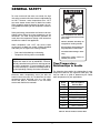
INSTALLATION AND OPERATING
INSTRUCTIONS
COLD WATER START & COLD WATER RUN
For Hi Delta & MVB
Heaters & Boilers
This manual should be maintained in legible condition and kept adjacent to the heater or in another safe place
for future reference.
Catalog No: 1000.57A
Effective: 02-28-07
Replaces: 02-24-06
P/N 241275 Rev. 2
2
GENERAL SAFETY
To meet commercial hot water use needs, the high
limit safety control on this water heater is adjustable up
to 210°F. However, water temperatures over 125°F
can cause instant severe burns or death from scalds.
When supplying general purpose hot water, the recommended initial setting for the temperature control is
125°F.
Safety and energy conservation are factors to be considered when setting the water temperature on the
thermostat. The most energy-efficient operation will
result when the temperature setting is the lowest that
satisfies the needs of the application.
Water temperature over 125°F can
cause instant severe burns or death
from scalds.
Children, disabled, and elderly are
at highest risk of being scalded.
Water temperature over 125°F can cause instant
severe burns or death from scalds. Children, disabled
and elderly are at highest risk of being scalded.
•
•
See instruction manual before setting temperature at water heater.
Feel water before bathing or showering.
Feel water before bathing or showering.
Temperature limiting valves are available.
Temperature limiting valves are
available, see manual.
NOTE: When this water heater is supplying general
purpose hot water for use by individuals, a thermostatically controlled mixing valve for reducing point of
use water temperature is recommended to reduce
the risk of scald injury. Contact a licensed plumber or
the local plumbing authority for further information.
Time/Temperature
Relationships in Scalds
The following chart details the relationship of water
temperature and time with regard to scald injury and
may be used as a guide in determining the safest
water temperature for your applications.
Maximum water temperatures occur just after the
heater’s burner has shut off. To determine the water
temperature being delivered, turn on a hot water
faucet and place a thermometer in the hot water
stream and read the thermometer.
Water
Temp.
Time to Produce
Serious Burn
120°F
More than 5 minutes
125°F
1-1/2 to 2 minutes
130°F
About 30 seconds
135°F
About 10 seconds
140°F
Less than 5 seconds
145°F
Less than 3 seconds
150°F
About 1-1/2 seconds
155°F
About 1 second
Table courtesy of The Shriners Burn Institute
Table A: Time to Produce Serious Burn
3
COLD WATER START
Before arriving at the job site to begin the installation,
it's important to first inspect the system and determine
what materials you will need. Some parts are included with the controller while others you will need to
provide.
1 Control Box
1 Temperature Sensor
1 Valve assembly with actuator (Shipped separately)
Wiring and mounting hardware (Provided by installer)
INSTALLATION
Check the Power Source
Fig. 2: Multi-meter
CAUTION: Do not use for swimming pool applications
so as to provide maximum support by using the
mounting holes provided on the base of the controller
to the side center brace on the heater. You will need to
drill mounting holes and holes through the heater side
panel for the routing of wiring and the sensor. A template is supplied for field-installed kits to locate the
control box properly.
WARNING: Using a multi-meter, check the following voltages at the circuit breaker panel prior to connecting any equipment. Make sure proper polarity is
followed and house ground is proven.
BLACK
Attaching the Temperature
Sensor
CIRCUIT
BREAKER
WHITE
Avoid routing wiring on or near other electrical wires,
conduit, motors, spark igniters or other sources of
high, intermittent voltage or current. The sensor should
be placed in the dry well on the inlet header. Ensure it
is installed using thermopaste (field supplied) and it is
held firmly at the bottom of the well.
GREEN
GROUND
A B
Connecting the Valve
Assembly
C
Fig. 1: Wiring Connections
Connect valve assembly “T CONNECTION “ into the
piping with the actuator input wiring facing the heater
side panel, as shown below. Route wiring to the control thru the bottom panel knockouts to TB2. Refer to
the wiring diagram provided on the inside of control
cover assembly.
Check the power source:
AC = 108 VAC Minimum, 132 VAC MAX
AB = 108 VAC Minimum, 132 VAC MAX
BC = <1 VAC Maximum
Mounting the Control Box
NOTE: Four knockouts are located on the bottom
of the control for ease of installation.
The control box should be mounted on the side of the
heater to which the system piping and valve assembly
are to be attached. The controller should be mounted
4
NOTE: If a “DIP” switch is provided on the control
PCB, verify that the switch settings are correct: 1 =
OFF, 2 = ON, 3 = OFF.
OPERATION
Verify the following upon a CALL FOR HEAT signal
from the heater:
1. CALL FOR HEAT LED on PCB illuminates GREEN.
2. START UP MODE LED on PCB illuminates YELLOW. Before 7 minutes it should go out if boiler
inlet temperature is approaching the set point temperature.
Models
X
302B-902B
7.0″
992B-2342B
13.20″
CALL FOR HEAT
START UP MODE
INLET TEMP ERROR
SENSOR OUT OF RANGE
LEFT SIDE
Fig. 3: Component Locations — Hi Delta
Connecting Power to the
Controller
Set
Point
Pot
Supply power from the 120 VAC power input from the
heater to the controller power inputs Terminal Block
(TB1). This is accomplished by connecting wiring from
the control box to the heater TB1 board 120 VAC
power input connections. Refer to wiring diagrams.
Fig. 5: Control PCB
3. The “ACTUATOR” should be in the fully open position or move to the fully open position if not already
there. (Actuator at the fully CCW position)
4. Before 7 minutes time has elapsed if the control is
operating properly the “START UP MODE” LED
should go out. The inlet water temperature should
be stable at a temperature between 105° F and
120° F (Normally set to 110° F) cooresponding to
the Set Point Pot setting on the PCB. The actuator
should have stopped moving.
Reset Switch
Fig. 4: Location of TB1 in Control Box
5
16) Once the NO contacts of the DPST close, the
heater 24 VAC is sent back to the heater to complete the Economaster circuit (pin 3 of terminal
block 3) and the interlock circuit (pin 1 of terminal
block 3) allowing the heater to fire.
17) Pin FR on the TVC board outputs 10VDC to the
modulating three way valve actuator to drive it fully
open for two-minutes waiting for the heater to
reach full fire.
18) After the two-minute delay the 10VDC output signal from pin FR reduces to approximately 8VDC at
the inverter thus slowing the pump to approximately 50 Hz.
19) The output signal continues to vary depending on
the heater inlet temperature.
NOTE: The minimum return water temperature to
the heater to prevent condensate is 105°F on standard heaters and 120°F on 87% Efficiency heaters.
Ensure that during operation the Set Point Pot is
adjusted properly.
Cold Start Sequence of
Operation
1) 120VAC to heater sends 120VAC to Cold Start
control on terminal block 1.
2) 120/24VAC transformer and 120VAC-12VDC converter are powered.
3) 120/24VAC transformer outputs 24VAC to pin 2 of
terminal block 2
4) 24VAC leaves pin 2 of terminal block 2 and goes
to the modulating three way valve on the 2030VAC lead, and to the NO contacts of the SPST
relay located in the cold start control panel.
5) 120VAC-12VDC converter outputs 12VDC to pin 3
of terminal block 2.
6) The 12VDC signal leaves pin 2 of terminal block 2
and goes to the common terminal of the reset
switch, located on the bottom of the cold start control panel.
7) The 12VDC signal crosses over the reset switch
and goes to Pin FS on cold start circuit board.
8) Cold start control remains on standby until a Call
for heat occurs at heater.
9) TRIG terminal of Economaster connection on
heater CPW board outputs 24VAC to terminal 4 of
terminal block 3 located in Cold Start controller.
10) Terminal 4 of TB 3 sends 24VAC to the coil of the
SPST relay located in the cold start control panel.
11) The SPST relay coil is energized and closes the
contacts allowing 24VAC to energize the CFH pin
on the cold start circuit board.
a) A two second delay occurs from the CFH signal
waiting to send power from terminal MC of the cold
start circuit board.
12) J9 terminal on the heater CPW board (interlock
connection) outputs a 24 VAC signal to terminal 2
of terminal block 3 located in the cold start controller.
13) 24 VAC is sent from terminal 2 of terminal block 3
to the NO contacts of the DPST relay located in
the cold start control panel.
14) After the two second delay on the cold start circuit
board, pin MC outputs a 24 VAC signal to the coil
of the DPST relay located in the cold start control
panel.
15) The DPST relay coil energizes and closes the NO
contacts.
The heater will lockout and shut down if the set point
on the inlet temperature is not achieved within sevenminutes from a call for heat.
The DIP switches on the 3-way valve actuator must be
set as indicated in the Fig. 6.
MODE SELECTION SWITCH
DIP SWITCH SETTINGS
FOR 3-WAY ACTUATOR
VDC
mA
0-10
2-10
DA
RA
FIXED
AUTO
~
6-9
DIRECT ACTING, ON INCREASING SIGNAL
SWITCH MUST BE IN THIS POSITION
TURN CLOCKWISE TO FURTHEST STOP
Fig. 6: Set Dip Switch Settings — Delta Actuator
Fig. 7: Delta Actuator — Actuator Shown in Full System
Flow Position
6
TROUBLESHOOTING
Check your power source using a Volt-Ohm meter;
check the following voltages at TB1 terminal block:
TB1-1 to TB1-2 = 108 VAC Minimum, 132 VAC
Maximum
TB1-1 to TB1-3 = 108 VAC Minimum, 132 VAC
Maximum
TB1-2 to TB1-3 = Must be less than .6 VAC
IF CALL FOR HEAT LED does not illuminate when the
heater has a CFH signal, check for 24VAC at the
heater CPW Board (J17-TRIG) output. If voltage is
present, check wiring using the wiring diagram. If voltage is not present, the problem exists in the heater.
IF VALVE DOES NOT MOVE: Check for voltage out at
TB2-1: Should be a 1VDC to 10VDC output to the
actuator valve. If no voltage is present, check for voltage at TB2-3, there should be a 12VDC signal. If the
12VDC signal is not present, verify that the converter
is wired correctly using the wiring diagram.
Fig. 8: Elodrive Actuator — Rotation Knob Setting
IF SENSOR OUT OF RANGE LED is illuminated: The
set point temperature has not been reached within the
7 minute time period.
• Push the Reset Switch (see Fig. 4) or remove
power and watch for proper operation.
• Check pump sizing and valve/piping sizing and correct as necessary.
• Replace sensor.
• Check wiring using wiring diagram.
Fig. 9: Elodrive Actuator — Actuator Shown in Full
System Flow Position
NOTE: Elodrive actuator is Nema 4 rated.
7
Cold Water Start Troubleshooting Guide
8
Wiring Diagram
9
COLD WATER RUN
Installation Codes
Installations must be in accordance with local, state,
provincial, and national codes, laws, regulations and
ordinances. In the absence of local codes, installations must be in accordance with the latest editions of
the:
• National Fuel Gas Code, ANSI Z223.1/NFPA 54
• National Electrical Code, ANSI/NFPA 70
• For Canada only: CAN/CGA B149.1 installation
Code (B149.1) and CSA C22.1 C.E.C. Part 1 and
Part 2
Purpose
The Cold Water Run system utilizes a variable-speed
pump to inject the proper amount of water from the
main system loop into the boiler to maintain the optimum inlet temperature. This approach allows the full
capacity of the boiler to be utilized to meet the system
load, while at the same time continuously maintaining
the optimum inlet water temperature to prevent condensation.
Mounting the Control Box
Typical Cold Water Run
Applications
•
•
•
•
•
NOTE: The heater should not be located in an area
where possible water leakage will result in damage
to the area adjacent to the heater or to the structure.
When such locations cannot be avoided, it is recommended that a suitable drain pan, with adequate
drainage, be installed under the heater. The pan
must not restrict combustion air flow.
Swimming pools.
Snow melting.
Low temperature radiant panel.
Water source heat pumps.
Any system with steady state return water temperature below 105°F.
The control box should be mounted on the side of the
heater to which the system piping and pump assemblies are to be attached. The controller should be
mounted so as to provide maximum support by using
the mounting holes provided on the base of the controller to the side center brace on the heater. You will
need to drill mounting holes and holes through the
heater side panel for the routing of wiring and the sensor. A template is supplied for field-installed kits to
locate the control box properly.
CWR vs. CWS
•
•
•
•
Cold water start is for transient cold water operation.
Cold water run is for continuous operation below
105°F system return temperature.
Cold water start maintains design flow rate at system design temperature but reduces bolier flow
rate during heavy by-pass operation.
Cold water run maintains constant design flow rate
in the boiler.
CAUTION: Remote mounted controller must be
installed within 25 feet of the heater.
Indoor and Outdoor
Installations
INSTALLATION
The cold water run control panel is rated for indoor use
only. Do not mount or install the control panel in areas
where dripping, flooding, rain, snow or spraying water
may come in contact with the enclosure. If the injection
pump is located outdoors, the optional outdoor cover
must be installed according to the instructions in the
following section. For outdoor installations mount the
control panel indoors and route the wiring to the appropriate connection points. Wire length is not to exceed
25 feet in any one direction. Contact your local sales
representative for further information.
Before arriving at the job site to begin the installation,
it's important to first inspect the system and determine
what materials you will need. Some parts are included with the controller while others you will need to
provide.
10
Injection & Heater Pump Comparison — Hi Delta
Heater Pump
Heater
Model
Flow
302
32
16
402
34
502
Injection Pump
Flow
Temp. Rise
Injection
Pump
Heater Pump
2
13
40
1911-1⁄4 hp
112
20
2
17
40
1911-1⁄4 hp
112
42
20
2.3
22
40
1911-1⁄4 hp
1630 4.0
652
55
20
4.1
28
40
1911-1⁄4 hp
1630 4.0
752
63
20
5.7
32
40
1911-1⁄4 hp
1630 4.2
902
76
20
8.4
38
40
1911-1⁄4 hp
1630 4.2
992
83
20
5.2
42
40
1911-1⁄4 hp
1630 4.7
1262
107
20
9.6
54
40
1911-1⁄3hp
1630 4.7
1532
120
22
12.4
62
42
1911-1⁄3hp
1632 5.6
1802
120
25
13
68
45
1911-1⁄3hp
1632 5.6
2002
132
26
19
74
46
1935-3⁄4hp
1634 6.1
2072
132
27
19
75
47
1935-3⁄4hp
1634 6.1
2342
132
30
21.4
80
50
1935-3⁄4hp
1634 6.1
Temp. Rise Press. Drop
Table B: Injection and heater pump specifications
Check the Power Source
Check the power source:
AC = 108 VAC Minimum, 132 VAC MAX
AB = 198 VAC Minimum, 250 VAC MAX
BC = 108-132 VAC Maximum
WARNING: Using a multi-meter, check the following voltages at the circuit breaker panel prior to connecting any equipment. Make sure proper polarity is
followed and house ground is proven.
BLACK
CIRCUIT
BREAKER
WHITE
GREEN
GROUND
A B
C
Fig. 11: Multi-meter
Fig. 10: Wiring Connections
11
Injection Pump Cover
Installation
Before Starting
1) Turn off power to the unit at the circuit breaker.
2) Turn off gas supply.
3) Shut off the water supply to the heater and, if necessary, drain water from the system.
4) Allow heater to cool down before attempting work.
In order to install the pump cover, you will need to
rotate the pump body so that the electrical box is pointing downward, as outlined in the following steps:
1. Loosen and remove the eight (8) 9/16” wrench
bolts holding the pump body in place. See Fig. 12.
Fig. 13: Remove the pump body
Fig. 12: Remove the eight bolts holding the pump body
in place
2. Remove the pump body then rotate it so that the
electrical box is pointing downward, ensuring not
to damage the seal. See Fig. 13, 14 and 15.
Fig. 14: Be sure not to damage the seal when removing
or replacing the pump body
12
Fig 17: Pump cover - angle view
Fig 15: Reposition the pump body so that the electrical
box points downward
3. Insert and tighten all eight (8) wrench bolts, securing the pump body in place.
4. You will now be able to install the pump cover. See
Fig. 18 and 19.
Fig. 16: Place the cover on the pump
13
Typical Boiler Piping (Hi Delta shown)
14
START-UP PROCEDURE
•
•
•
•
the cold run control panel.
8) After the two second delay on the cold run circuit
board, pin MC outputs a 24 VAC signal to terminal
AL0 of the Hitachi inverter.
9) The AL0 relay closes and outputs a 24 VAC signal
to the coil of the DPST relay located in the cold run
control panel.
10) The DPST relay coil energizes and closes the NO
contacts.
11) Once the NO contacts of the DPST close, the
heater 24 VAC is sent back to the heater to complete the Economaster circuit (pin 3 of terminal
block 3) and the interlock circuit (pin 1 of terminal
block 3) allowing the heater to fire.
12) Pin SC of the cold run circuit board sends 24VAC
to Pin 1 (Forward) on Hitachi Inverter.
13) PCS terminal on Inverter outputs 12VDC signal to
the common terminal of the reset switch located
on the bottom of the cold run control panel.
14) The 12VDC signal crosses over the reset switch
and goes to Pin FS on cold run circuit board.
15) 12VDC on pin FS is jumpered to pin S1 on the
cold run circuit board.
16) Pin FR on the TVC board outputs 10VDC to the
Inverter to drive injector pump at full speed twominutes waiting for the heater to reach full fire.
17) After the two-minute delay the 10VDC output signal from pin FR reduces to approximately 8VDC at
the inverter thus slowing the pump to approximately 50 Hz.
18) The output signal continues to vary depending on
the heater inlet temperature.
Run full system flow for two minutes.
Initiate PID pump control to achieve target inlet
temperature by slowing injector pump.
Boiler ΔT will not increase during bypass operation.
If target temperature is not achieved after seven
minutes from “call for heat”, the system will shut
down.
Fig. 18: Control Board
Sequence of Operation
The heater will lockout and shut down if the set point
on the inlet temperature is not achieved within sevenminutes from a call for heat.
1) Supply separate 220VAC, 1 Ø, 60 Hz power to
Cold Run control.
2) Call for heat occurs at heater.
3) TRIG terminal of Economaster connection on
heater CPW board outputs 24VAC to terminal 4 of
terminal block 3 located in Cold Run controller.
4) Terminal 4 of TB 3 sends 24VAC to the coil of the
SPST relay located in the cold run control panel.
5) The SPST relay coil is energized and closes the
contacts allowing 24VAC from the Cold Run control transformer to be sent to the CFH terminal of
the Cold Run circuit board.
a) A two second delay occurs from the CFH signal
waiting to send power from terminal MC of the cold
run circuit board.
6) J9 terminal on the heater CPW board (interlock
connection) outputs a 24 VAC signal to terminal 2
of terminal block 3 located in the cold run controller.
7) 24 VAC is sent from terminal 2 of terminal block 3
to the NO contacts of the DPST relay located in
The DIP switches on the Hitachi Inverter must be set
as indicated on Fig. 19 below.
Fig. 19: DIP Switch Settings
15
Wiring Diagram
16
Cold Water Run Troubleshooting Guide
Step 1
Does TB1 of cold run
controller have 120
VAC?
Is there a Call For
Heat at the heater?
YES
YES
Step 2
Verify 120VAC from
TB1 on the heater
and correct
NO
NO
Is the 220VAC inverter in the
cold run controller powered?
NO
Heater is in standby mode
Correct Wiring
YES
Step 3
Does the cold run inverter output
12VDC from PCS to pin FS?
NO
Replace inverter or install jumper
and correct switch settings
YES
Step 4
Is 24VAC present at Poolstat
connection on cold run circuit
board?
NO
Check 24VAC output at J17 of
heater circuit board and correct
YES
Step 5
Does cold run relay K-6
coil receive 24VAC from
MC on circuit board?
Replace circuit board
NO
Call our Technical Service Department
1-800-927-2975 Outside California
1-800-627-2975 Inside California
YES
Step 6
Are the Economaster and
Interlock leads connected to
N.O. contacts of relay K-6?
NO
YES
Correct wiring
Is sensor resistance correct?
YES
NO
Replace sensor
Step 7
Are the Economaster
and Interlock leads
connected correctly to
heater CPW board?
Correct 3Ø pump wiring
Correct wiring
NO
NO
YES
YES
Step 8
Step 9
Is the injector pump
modulating after 2-1/2
YES
Is the heater tripping the high
limit?
Verify pump is rotating in proper
direction
YES
Pump must decrease
RPM’s on decreasing 010VDC signal
NO
NO
The unit is okay
Is 0-10VDC present at
connection FR of cold run circuit
board?
NO
Replace cold run circuit board
NO
Step 10
YES
Does cold run circuit board lock-out on
“Sensor out of Range”?
17
YES
ILLUSTRATED PARTS LISTS
Cold Water Start
18
2-M
1-M
3-M
4-M
CALL OUT
DESCRIPTION
HI DELTA
MVB
1-C
PC BOARD ASSY-CONTROL
011717F
011717F
2-C
TRANSFORMER
011718F
011718F
3-C
POWER SUPPLY 120VAC/12VDC
011719F
011719F
4-C
RELAY-DPDT 24V
011720F
011720F
5-C
RELAY-SPDT 24V
009039F
009039F
6-C
GROUND LUG
007155F
007155F
7-C
TEMP SENSOR 10K (NOT SHOWN)
010787F
010787F
8-C
RESET SWITCH
005641F
005641F
1-M
PUMP-WATER BR 2" FLANGE, 1/4 HP
007226F
007226F
PUMP-WATER CI 2" FLANGE, 1/4 HP
007232F
007232F
PUMP-WATER BR 2" FLANGE, 1/2 HP
N/A
007347F
PUMP-WATER CI 2" FLANGE, 1/2 HP
PUMP-WATER BR 2-1/2" FLANGE, 3/4 HP
007353F
007348F
PUMP-WATER CI 2-1/2" FLANGE, 3/4 HP
007354F
007354F
PUMP-WATER BR 2-1/2" FLANGE, 1 HP
007348F
007348F
PUMP-WATER CI 2-1/2" FLANGE, 1 HP
007354F
007354F
N/A
007937F
N/A
007938F
PUMP-WATER BR 2-1/2" FLANGE, 1.5 HP
PUMP-WATER CI 2-1/2" FLANGE, 1.5 HP
2-M
N/A
007348F
3-WAY VALVE 2 NPT 24 Cv
011939F
011939F
3-WAY VALVE 2 NPT 38 Cv
011721F
011721F
3-WAY VALVE 2 NPT 57 Cv
011722F
011722F
3-WAY VALVE 2-1/2 NPT 74 Cv
011723F
011723F
3-WAY VALVE 2-1/2 NPT 100 Cv
011724F
011724F
3-M
ACTUATOR
011834F
011834F
4-M
THERMOMETER-VERTICAL
000919
000919
1-S
CONTROL BOX SHEET METAL
011716F
011716F
2-S
CONTROL BOX COVER
N/A
011978F
NOTE: Sizing is specific to this application.
19
Cold Water Run
20
CALL
OUT
1-C
DESCRIPTION
HI DELTA
MVB
PC BOARD ASSY-CONTROL
011717F
011717F
2-C
RELAY-DPDT 24VAC
011720F
011720F
3-C
RELAY-SPDT 24VAC
009039F
009039F
4-C
INVERTER-1/2 HP
011835F
011835F
INVERTER-1 HP
011836F
011836F
5-C
TRANSFORMER-115/230 VAC
011718F
011718F
6-C
TEMPERATURE SENSOR 10K (NOT SHOWN)
010787F
010787F
7-C
ALARM RESET SWITCH
005641F
005641F
1-M
PUMP-WATER BR 2" FLANGE, 1/4 HP
007226F
007226F
PUMP-WATER CI 2" FLANGE, 1/4 HP
007232F
007232F
PUMP-WATER BR 2-1/2" FLANGE, 3/4 HP
007348F
007348F
PUMP-WATER CI 2-1/2" FLANGE, 3/4 HP
007354F
007354F
PUMP-WATER BR 2-1/2" FLANGE, 1 HP
007351F
007351F
PUMP-WATER CI 2-1/2" FLANGE, 1 HP
007357F
007357F
2-M
THERMOMETER-VERTICAL
000919
000919
3-M
INJECTOR PUMP, BR 302B-902B (NOT SHOWN)
951414
N/A
INJECTOR PUMP, CI 302B-902B (NOT SHOWN)
951415
N/A
INJECTOR PUMP, BR 992B-1802B (NOT SHOWN)
951394
N/A
INJECTOR PUMP, CI 992B-1802B (NOT SHOWN)
951413
N/A
INJECTOR PUMP, BR 2002B-2342B (NOT SHOWN)
951411
N/A
INJECTOR PUMP, CI 2002B-2342B (NOT SHOWN)
951416
N/A
1-S
CONTROL BOX SHEET METAL
011716F
011716F
2-S
CONTROL BOX COVER
N/A
011978F
NOTE: Sizing is specific to this application.
21
www.raypak.com
Raypak, Inc., 2151 Eastman Avenue, Oxnard, CA 93030 (805) 278-5300 Fax (805) 278-5468
Raypak Canada Limited, 2805 Slough St., Mississauga, Ontario, Canada L4T 1G2 (905) 677-7999 Fax (905) 677-8036
Litho in U.S.A.