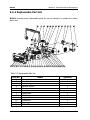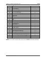
1
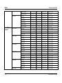
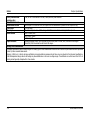
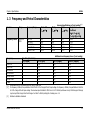
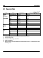
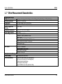
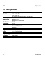
RIGOL Service Guide DM3068 Digital Multimeter Dec. 2010 RIGOL Technologies, Inc. RIGOL Guaranty and Declaration Copyright © 2010 RIGOL Technologies, Inc. All Rights Reserved. Trademark Information RIGOL is a registered trademark of RIGOL Technologies, Inc. Publication Number SGC06100-1110 Notices RIGOL products are protected by patent law in and outside of P.R.C. RIGOL reserves the right to modify or change parts of or all the specifications and pricing policies at company’s sole decision. Information in this publication replaces all previously corresponding material. RIGOL shall not be liable for losses caused by either incidental or consequential in connection with the furnishing, use or performance of this manual as well as any information contained. Any part of this document is forbidden to be copied or photocopied or rearranged without the express written approval of RIGOL. Product Certification RIGOL guarantees this product conforms to the national and industrial standards in China. International standard conformance certification is in progress. Contact Us If you have any problem or requirement when using our products, please contact RIGOL or your local distributors, or visit: www.rigol.com Service Guide for DM3068 I RIGOL Safety Requirement General Safety Summary Please review the following safety precautions carefully before putting the instrument into operation so as to avoid any personal injuries or damages to the instrument and any product connected to it. To prevent potential hazards, please use the instrument only specified by this manual. Use Proper Power Cord. Only the power cord designed for the instrument and authorized by local country could be used. Ground The Instrument. The instrument is grounded through the Protective Earth lead of the power cord. To avoid electric shock, it is essential to connect the earth terminal of power cord to the Protective Earth terminal before any inputs or outputs. Observe All Terminal Ratings. To avoid fire or shock hazard, observe all ratings and markers on the instrument and check your manual for more information about ratings before connecting. Use Proper Overvoltage Protection. Make sure that no overvoltage (such as that caused by a thunderstorm) can reach the product, or else the operator might expose to danger of electrical shock. Do Not Operate Without Covers. Do not operate the instrument with covers or panels removed. Use Proper Fuse. Please use the specified fuses. Avoid Circuit or Wire Exposure. Do not touch exposed junctions and components when the unit is powered. Do Not Operate With Suspected Failures. If you suspect damage occurs to the instrument, have it inspected by qualified service personnel before further operations. Any maintenance, adjustment or replacement especially to circuits or accessories must be performed by RIGOL authorized personnel. Keep Well Ventilation. Inadequate ventilation may cause increasing of temperature or damages to the device. So please keep well ventilated and inspect the intake and fan regularly. II Service Guide for DM3068 RIGOL Do Not Operate in Wet Conditions. In order to avoid short circuiting to the interior of the device or electric shock, please do not operate in a humid environment. Do Not Operate in an Explosive Atmosphere. In order to avoid damages to the device or personal injuries, it is important to operate the device away from an explosive atmosphere. Keep Product Surfaces Clean and Dry. To avoid the influence of dust and/or moisture in air, please keep the surface of device clean and dry. Electrostatic Prevention. Operate in an electrostatic discharge protective area environment to avoid damages induced by static discharges. Always ground both the internal and external conductors of the cable to release static before connecting. Handling Safety Please handle with care during transportation to avoid damages to keys, knob and, interfaces as well as other parts on the panels. The disturbance tests of all models conform to the P/F values of A based on the standard of EN 61326: 1997+A1+A2+A3 instead of P/F values of B. Input Terminal Protection Limit The protection limit is defined for the input terminal: 1. Main input (HI and LO) terminals HI and LO terminals are used for Voltage, Resistance, Capacitance, Continuity, Frequency and Diodes measurements and should be used under the following two conditions: 1) HI-LO protection: at most 1000 VDC or 750 VAC, this is also the maximum measurable voltage. The limit can be expressed as 1000 Vpk. 2) LO-ground protection: floating at 500 Vpk (relative) with safety. Since the HI terminal holds a maximum protection of 1000 Vpk relative to the ground, the sum of the “float” and measured voltages cannot exceed 1000 Vpk. 2. Sampling (HI Sense and LO Sense/200 mA) terminals HI Sense and LO Sense/200 mA terminals are used for 4-wire resistance measurement and should be used under two conditions: 1) HI Sense-LO Sense/200 mA protection limit: 200 Vpk. Service Guide for DM3068 III RIGOL 2) LO Sense/200 mA-LO protection limits: 0.5 Vpk. The current input fuse on the rear panel provides the current passing through LO Sense/200 mA up to 500 mA protection. 3. Current input (10 A and Sense/200 mA) terminals 10 A and LO terminals are used for current measurements of 2 A and 10 A. The maximum current going through the 10 A terminal is limited to 10 A by the internal fuse. LO Sense/200 mA and LO terminals are used for current measurements ranging from 200 A to 200 mA. The maximum current going through the LO Sense/200 mA terminal is limited to 500 mA by the internal fuse. NOTE: In order to prevent the fuse from blowing out and protect the multimeter, please use the current input terminals according to the following requirements: 1) Do not connect the 10 A and LO Sense/200 mA input terminals into the current measuring circuit at the same time. 2) Only use 10 A and LO terminals for measurements when the measured current AC+DC RMS value goes within 200 mA and 10 A. 3) Select a proper current input terminal according to the estimated current magnitude before connecting the multimeter to AC supplies if you want to use current measurement. 4) The current into the 10 A terminal cannot exceed 13.5 A, otherwise it will blow out the internal fuse; while the current into the LO Sense/200 mA terminal cannot exceed 650 mA, otherwise the current input fuse from the rear panel may be blown out. IEC II Overvoltage Protection In order to prevent electric shock, DM3068 provides overvoltage protection for line-voltage mains connections meeting both of the following conditions: 1. The HI and LO input terminals are connected to the mains under Measurement Category II conditions defined below. 2. The mains are limited to a maximum line voltage of 300 VAC. WARNING: IEC II includes electrical devices connected to mains through an outlet from the branch circuit. Such devices include most small appliances, test equipments and other devices inserted into a branch socket. DM3068 may be used to make measurements with the HI and LO inputs connected to mains in such devices (up to 300 VAC), or to the branch socket. , the HI and LO inputs of DM3068 cannot be connected to mains of permanently installed electrical devices such as a main circuit-breaker panel, sub-panel disconnected box or wired motors. Such devices and circuits are readily to beyond the protection of DM3068. IV Service Guide for DM3068 RIGOL NOTE: Voltages above 300 VAC may be measured only in circuits that are isolated from mains. However, a transient overvoltage is also present in such circuits. DM3068 was designed to safely withstand occasional transient overvoltage up to 2500 Vpk. Do not use this device to measure circuits whose transient overvoltage may exceed this level. Service Guide for DM3068 V RIGOL Safety Terms and Symbols Terms in this Manual. These terms may appear in this manual: WARNING Warning statements indicate the conditions or practices that could result in injury or loss of life. CAUTION Caution statements indicate the conditions or practices that could result in damage to this product or other property. CAT I(1000V) IEC Measurement Category I. The maximum voltage can be measured by HI-LO terminal is 1000Vpk. CAT II(300V) IEC Measurement Category II. Inputs may be connected to mains (up to 300VAC) in the case of overvoltage in Category II. Terms on the Product. These terms may appear on the product: DANGER indicates an injury or hazard may immediately happen. WARNING indicates an injury or hazard may be accessible potentially. CAUTION indicates a potential damage to the instrument or other property might occur. Symbols on the Product. These symbols may appear on the product: Hazardous Voltage VI Refer to Instructions Protective Earth Terminal Chassis Ground Test Ground Service Guide for DM3068 RIGOL General Care and Cleaning General Care: Do not store or leave the instrument at a place where the instrument will be exposed to direct sunlight for long periods of time. Cleaning: Clean the instrument regularly according to its operating conditions. To clean the exterior surface, perform the following steps: 1. Disconnect the instrument from all power sources. 2. Moisten a cloth slightly (using a mild detergent or water) and clean the loose dust on the outside of the instrument. Always take care when you clean the LCD in order to avoid scuffing it. CAUTION To avoid damages to the instrument, do not expose them to corrosive liquids. WARNING To avoid injury resulting from short circuit, make sure the instrument is completely dry before reconnecting into a power source. Service Guide for DM3068 VII RIGOL Environmental Considerations The following symbol indicates that this product complies with the applicable European Union requirements according to Directives 2002/96/EC on waste electrical and electronic equipment (WEEE) and batteries. Product End-of-Life Handling The equipment may contain substances that could be harmful to the environment or human health. In order to avoid release of such substances into the environment and harmful to human health, we encourage you to recycle this product in an appropriate system that will ensure that most of the materials are reused or recycled appropriately. Please contact your local authorities for disposal or recycling information. VIII Service Guide for DM3068 RIGOL Document Overview Chapter 1 Specifications This chapter lists specifications and characteristics. Chapter 2 Performance Test This chapter introduces how to test the performance of DM3068 so as to know its state well. Chapter 3 Calibration This chapter provides information about the calibration of DM3068. Chapter 4 Disassembly & Assembly This chapter guides you to disassemble and assemble DM3068 to reach a clearer understanding of its structure. Chapter 5 Troubleshooting & Maintenance This chapter guides you to eliminate possible errors caused during the measurement and contains information about routine maintenance. Service Guide for DM3068 IX RIGOL Table of Contents Guaranty and Declaration ........................................................................ I Safety Requirement ................................................................................. II General Safety Summary .......................................................................... II Safety Terms and Symbols ........................................................................VI General Care and Cleaning...................................................................... VII Environmental Considerations ................................................................ VIII Document Overview ................................................................................. IX Chapter 1 1. 1. 1. 1. 1. 1. 1. 1. 1 2 3 4 5 6 7 8 Chapter 2 Specifications .................................................................... 1-1 DC Characteristics ........................................................................ 1-1 AC Characteristics ........................................................................ 1-5 Frequency and Period Characteristics ............................................. 1-9 Capacitance Characteristics ......................................................... 1-11 Temperature Characteristics ........................................................ 1-12 Measurement Rate ..................................................................... 1-14 Other Measurement Characteristics .............................................. 1-15 General Specifications ................................................................ 1-16 Performance Test .............................................................. 2-1 2. 1 2. 2. 2. 2. Test Type .................................................................................... 2-1 2.1.1 Self-Test ................................................................................. 2-1 2.1.2 Fast Test ................................................................................ 2-3 2.1.3 Routine Test ........................................................................... 2-4 2 Testing Equipments ...................................................................... 2-5 3 Test Conditions ............................................................................ 2-6 4 Input Connections ........................................................................ 2-7 5 Routine Test ................................................................................ 2-8 2.5.1 Zero-offset Test ...................................................................... 2-8 2.5.2 Gain Test.............................................................................. 2-10 Chapter 3 3. 1 3. 2 3. 3 Chapter 4 4. 4. 4. 4. 4. 4. 4. X 1 2 3 4 5 6 7 Calibration ......................................................................... 3-1 Calibration Interval ....................................................................... 3-1 Calibration Notice ......................................................................... 3-1 To Obtain Calibration Service ......................................................... 3-1 Disassembly & Assembly ................................................... 4-1 Disassembly and Assembly Notices ................................................ 4-1 The 3D View of DM3068 ............................................................... 4-2 To Disassemble and Assemble Handle ............................................ 4-3 To Disassemble and Assemble Rear Panel ....................................... 4-4 To Disassemble and Assemble Metallic Shell ................................... 4-5 To Disassemble and Assemble Fuse Seat ........................................ 4-6 To Disassemble and Assemble GPIB PCB ........................................ 4-7 Service Guide for DM3068 RIGOL 4. 4. 4. 4. 4. 8 To Disassemble and Assemble Filter Board & Transformer ................ 4-8 9 To Disassemble and Assemble Front Panel & LCD ........................... 4-9 10 To Disassemble and Assemble the Fan ....................................... 4-10 11 To Disassemble and Assemble Mainboard .................................. 4-11 12 To Disassemble and Assemble Keypad PCB ................................ 4-12 Chapter 5 Troubleshooting & Maintenance......................................... 5-1 5.1 Troubleshooting ............................................................................... 5-1 5.2 Maintenance and Cleaning ................................................................ 5-4 5.2.1 System Maintenance ............................................................... 5-4 5.2.2 Principles of Circuit ................................................................. 5-4 5.2.3 Components Inspection ........................................................... 5-6 5.2.4 Replaceable Part list ............................................................... 5-10 5.2.5 Warranty .............................................................................. 5-12 Service Guide for DM3068 XI Chapter 1 Specifications Chapter 1 RIGOL Specifications 1. 1 DC Characteristics Function DC Voltage DC Current Resistance[6] Diode Test Range[2] 200.0000mV 2.000000V 20.00000V 200.0000V 1000.000V[4] 200.0000uA 2.000000mA 20.00000mA 200.0000mA 2.000000A 10.00000A[5] 200.0000Ω 2.000000kΩ 20.00000kΩ 200.0000kΩ 1.000000MΩ 10.00000MΩ 100.0000MΩ 2.0000V[7] Service Guide for DM3068 Test Current or Burden Voltage 24 Hour[3] TCAL℃± 1℃ <0.03V <0.25V <0.07V <0.7V <0.12V <0.6V 1mA 1mA 100uA 10uA 2uA 200nA 200nA || 10MΩ 1mA 0.0020+ 0.0020 0.0015 + 0.0005 0.0020 + 0.0004 0.0020 + 0.0006 0.0020 + 0.0006 0.010 + 0.012 0.007 + 0.003 0.007 + 0.012 0.010 + 0.002 0.050 + 0.020 0.100 + 0.010 0.0030 + 0.0030 0.0020 + 0.0005 0.0020 + 0.0005 0.0020 + 0.0005 0.002 + 0.001 0.015 + 0.001 0.300 + 0.010 0.002 + 0.010 Accuracy Specifications: ± (% of reading + % of range)[1] Temperature 90 Day 1 Year Coefficient TCAL℃± 5℃ TCAL℃± 5℃ 0℃ to (TCAL℃-5℃) (TCAL℃+5℃) to 50℃ 0.0030 + 0.0025 0.0040 + 0.0025 0.0005 + 0.0005 0.0020 + 0.0006 0.0035 + 0.0006 0.0005 + 0.0001 0.0030 + 0.0005 0.0040 + 0.0005 0.0005 + 0.0001 0.0040 + 0.0006 0.0050 + 0.0006 0.0005 + 0.0001 0.0040 + 0.0010 0.0055 + 0.0010 0.0005 + 0.0001 0.040 + 0.015 0.050 + 0.015 0.0020 + 0.0030 0.030 + 0.003 0.050 + 0.003 0.0020 + 0.0005 0.030 + 0.015 0.050 + 0.015 0.0020 + 0.0020 0.030 + 0.003 0.050 + 0.003 0.0020 + 0.0005 0.080 + 0.020 0.100 + 0.020 0.0050 + 0.0010 0.120 + 0.010 0.150 + 0.010 0.0050 + 0.0020 0.008 + 0.004 0.010 + 0.004 0.0006 + 0.0005 0.008 + 0.001 0.010 + 0.001 0.0006 + 0.0001 0.008 + 0.001 0.010 + 0.001 0.0006 + 0.0001 0.008 + 0.001 0.010 + 0.001 0.0006 + 0.0001 0.010 + 0.001 0.012 + 0.001 0.0010 + 0.0002 0.030 + 0.001 0.040 + 0.001 0.0030 + 0.0004 0.800 + 0.010 0.800 + 0.010 0.1500 + 0.0002 0.008 + 0.020 0.010 + 0.020 0.0010 + 0.0020 1-1 RIGOL Chapter 1 Specifications Continuity Test 2000.0Ω 1mA 0.002 + 0.010 0.008 + 0.020 0.010 + 0.020 0.0010 + 0.0020 [1] Specifications are for 90-minute warm-up and 100NPLC integration time. For integration time <100NPLC, add the appropriate “RMS Noise Adder” listed in the following table. [2] 10% overrange on all ranges except DCV 1000V and DCI 10A range. [3] Relative to calibration standards. [4] For each additional volt over ± 500 V, add 0.03mV error. [5] For continuous current > 7A DC or 7A AC RMS, 30 seconds ON and 30 seconds OFF. [6] Specifications are for 4–wire resistance measurement or 2–wire resistance measurement using REL operation. Without REL operation, add 0.2 Ω additional errors in 2-wire resistance measurement. [7] Accuracy specifications for the voltage measured at the input terminal only. 1 mA test current is typical. Variation in the current source will create some variation in the voltage drop across a diode junction. Performance Versus Integration Time – 50Hz (60Hz) Power-line Frequency Integration Readings/s[3] RMS Noise Adder [4] (% of Range) Time DCV 2V Number of Resolution[1] NMRR[2] DCV 1000V DCV 200mV 200V Power line (ppm Range) (dB) 50Hz 60Hz DCV 20V DCI 2mA Resistance 200Ω Resistance 2kΩ Cycles 200mA DCI 10A 20kΩ (NPLC) 0.006 2.7 0 10000 10000 0.0006 0.0007 0.0015 0.0040 0.02 1.6 0 2500 3000 0.0004 0.0004 0.0008 0.0025 0.06 1 0 833 1000 0.0003 0.0003 0.0006 0.0025 0.2 0.5 0 250 300 0.0001 0.0002 0.0003 0.0015 1 0.22 60 50 60 0 0.0001 0.0002 0.0004 2 0.17 60 25 30 0 0 0.0001 0.0003 10 0.08 60 5 6 0 0 0 0.0002 100 0.035 60 0.5 0.6 0 0 0 0 [1] Typical value. Resolution is defined as the typical 20V range RMS noise (using auto zero “Once”). [2] Normal mode rejection ratio for power-line frequency ± 0.1%. For power-line frequency ± 1%, subtract 20dB. For ± 3%, subtract 30dB. [3] Maximum rate for DCV, DCI, 2-wire resistance and 4-wire resistance functions. 1-2 Service Guide for DM3068 Chapter 1 Specifications [4] RIGOL The basic DC accuracy specifications include RMS noise at 100 NPLC. For <100 NPLC, add “RMS Noise Adder” to the basic DC accuracy specifications. SFDR & SINAD[1] Function Range Spurious-Free Dynamic Range (SFDR) Signal-to-Noise-and-Distortion (SINAD) DCV 200mV 81 76 2V 79 78 20V 79 75 200V 83 80 1000V 86 82 DCI 200uA 89 69 2mA 86 81 20mA 88 69 200mA 81 79 2A 69 64 [1] Typical value. -1dBFS, 1kHz single tone. 100us aperture time, zero trigger delay, auto zero off and 4096 samples. Measuring Characteristics DC Voltage Input Resistance Input Protection Input Offset Current CMRR (common mode rejection ratio) Resistance Measurement Method Open-circuit Voltage Max. Lead Resistance (4-wire) Service Guide for DM3068 200mV, 2V, 20V ranges: Selectable 10MΩ or >10GΩ (For these ranges, input beyond ± 26V are clamped through 106kΩ (typical) ) 200V and 1000V ranges: 10MΩ±1% 1000V 50pA, at 25℃, typical 140dB for 1 kΩ unbalance in LO lead, ± 500VDC peak maximum. Selectable 4-wire or 2-wire resistance Current source referenced to LO input Limited to <10V 10% of range per lead for 200 Ω, 2 kΩ ranges, 1 kΩ per lead on all other ranges 1-3 Chapter 1 Specifications RIGOL Input Protection Offset Compensation DC Current Shunt Resistor Input Protection 1000V on all ranges Available on 200Ω, 2kΩ and 20 kΩ ranges. 100Ω for 200uA, 2mA 1Ω for 20mA , 200mA 0.01Ω for 2A, 10A Externally accessible 500mA, 250V fast blow fuse at the rear panel for 200uA, 2mA, 20mA and 200mA ranges. Internal 10A, 250 V slow blow fuse for 2A and 10A ranges. Continuity/Diode Test Response Time 300 samples/sec, with audible tone Continuity Threshold Adjustable from 1 Ω to 2000 Ω Autozero OFF Operation (typical value) Following instrument warm-up at the environment temperature ± 1℃ and <5 minutes, add 0.0001 % range + 2 uV for DCV and 2 mΩ for resistance. Settling Time Considerations Reading settling times are affected by source impedance, cable dielectric characteristics and input signal changes. The default measurement delay is selected to give first reading right for most measurements. Measurement Considerations Telon or other high-impedance, low-dielectric absorption wire insulation is recommended for these measurements. 1-4 Service Guide for DM3068 Chapter 1 Specifications RIGOL 1. 2 AC Characteristics [2] Function Range True RMS AC Voltage [4] 200.0000mV 2.000000V 20.00000V 200.0000V Service Guide for DM3068 Frequency Range 3Hz- 5Hz 5Hz-10Hz 10Hz-20kHz 20kHz-50kHz 50kHz-100kHz 100kHz- 300kHz 3Hz-5Hz 5Hz-10Hz 10Hz-20kHz 20kHz-50kHz 50kHz-100kHz 100kHz - 300kHz 3Hz-5Hz 5Hz-10Hz 10Hz-20kHz 20kHz- 50kHz 50kHz-100kHz 100kHz-300kHz 3Hz-5Hz 5Hz-10Hz 10Hz-20kHz 20kHz-50kHz Accuracy Specifications: ± (% of reading + % of range)[1] 24 Hour 90 Day 1 Year Temperature TCAL℃± 1℃ TCAL℃± 5℃ TCAL℃± 5℃ Coefficient 0℃ to (TCAL℃-5℃) (TCAL℃+5℃) to 50℃ 1.00 + 0.03 1.00 + 0.04 1.00 + 0.04 0.100 + 0.004 0.35 + 0.03 0.35 + 0.04 0.35 + 0.04 0.035 + 0.004 0.04 + 0.03 0.05 + 0.04 0.06 + 0.04 0.005 + 0.004 0.10 + 0.05 0.11 + 0.05 0.12 + 0.05 0.011 + 0.005 0.55 + 0.08 0.60 + 0.08 0.60 + 0.08 0.060 + 0.008 4.00 + 0.50 4.00 + 0.50 4.00 + 0.50 0.20 + 0.02 1.00 + 0.02 1.00 + 0.03 1.00 + 0.03 0.100 + 0.003 0.35 + 0.02 0.35 + 0.03 0.35 + 0.03 0.035 + 0.003 0.04 + 0.02 0.05 + 0.03 0.06 + 0.03 0.005 + 0.003 0.10 + 0.04 0.11 + 0.05 0.12 + 0.05 0.011 + 0.005 0.55 + 0.08 0.60 + 0.08 0.60 + 0.08 0.060 + 0.008 4.00 + 0.50 4.00 + 0.50 4.00 + 0.50 0.20 + 0.02 1.00 + 0.03 1.00 + 0.04 1.00 + 0.04 0.100 + 0.004 0.35 + 0.03 0.35 + 0.04 0.35 + 0.04 0.035 + 0.004 0.04 + 0.04 0.07 + 0.04 0.08 + 0.04 0.008 + 0.004 0.10 + 0.05 0.12 + 0.05 0.15 + 0.05 0.012 + 0.005 0.55 + 0.08 0.60 + 0.08 0.60 + 0.08 0.060 + 0.008 4.00 + 0.50 4.00 + 0.50 4.00 + 0.50 0.20 + 0.02 1.00 + 0.02 1.00 + 0.03 1.00 + 0.03 0.100 + 0.003 0.35 + 0.02 0.35 + 0.03 0.35 + 0.03 0.035 + 0.003 0.04 + 0.02 0.07 + 0.03 0.08 + 0.03 0.008 + 0.003 0.10 + 0.04 0.12 + 0.05 0.15 + 0.05 0.012 + 0.005 [3] 1-5 Chapter 1 Specifications RIGOL 750.000V[5] True RMS AC Current [8] 200.0000uA 2.000000mA 20.00000mA 200.0000mA 2.000000A 10.00000A[6] 1-6 50kHz-100kHz 100kHz-300kHz 3Hz-5Hz 5Hz-10Hz 10Hz-20kHz 20kHz-50kHz 50kHz-100kHz 100kHz-300kHz 3Hz-5Hz 5Hz-10Hz 10Hz-5kHz 5kHz-10kHz 3Hz-5Hz 5Hz-10Hz 10Hz-5kHz 5kHz-10kHz 3Hz-5Hz 5Hz-10Hz 10Hz-5kHz 5kHz-10kHz 3Hz-5Hz 5Hz-10Hz 10Hz-5kHz 5kHz-10kHz 3Hz-5Hz 5Hz-10Hz 10Hz-5kHz 5kHz-10kHz 3Hz-5Hz 0.55 + 0.08 4.0 + 0.50 1.00 + 0.02 0.35 + 0.02 0.04 + 0.02 0.10 + 0.04 0.55 + 0.08 4.0 + 0.50 1.10 + 0.06 0.35 + 0.06 0.15 + 0.06 0.35 + 0.70 1.00 + 0.04 0.30 + 0.04 0.12 + 0.04 0.20 + 0.25 1.10 + 0.06 0.35 + 0.06 0.15 + 0.06 0.35 + 0.70 1.00 + 0.04 0.30 + 0.04 0.10 + 0.04 0.20 + 0.25 1.10 + 0.06 0.35 + 0.06 0.15 + 0.06 0.35 + 0.70 1.10 + 0.08 0.60 + 0.08 4.0 + 0.50 1.00 + 0.03 0.35 + 0.03 0.07 + 0.03 0.12 + 0.05 0.60 + 0.08 4.0 + 0.50 1.10 + 0.06 0.35 + 0.06 0.15 + 0.06 0.35 + 0.70 1.00 + 0.04 0.30 + 0.04 0.12 + 0.04 0.20 + 0.25 1.10 + 0.06 0.35 + 0.06 0.15 + 0.06 0.35 + 0.70 1.00 + 0.04 0.30 + 0.04 0.10 + 0.04 0.20 + 0.25 1.10 + 0.06 0.35 + 0.06 0.15 + 0.06 0.35 + 0.70 1.10 + 0.10 0.60 + 0.08 4.0 + 0.50 1.00 + 0.03 0.35 + 0.03 0.08 + 0.03 0.15 + 0.05 0.60 + 0.08 4.0 + 0.50 1.10 + 0.06 0.35 + 0.06 0.15 + 0.06 0.35 + 0.70 1.00 + 0.04 0.30 + 0.04 0.12 + 0.04 0.20 + 0.25 1.10 + 0.06 0.35 + 0.06 0.15+ 0.06 0.35 + 0.70 1.00 + 0.04 0.30 + 0.04 0.10 + 0.04 0.20 + 0.25 1.10 + 0.06 0.35 + 0.06 0.15 + 0.06 0.35 + 0.70 1.10 + 0.10 0.060 + 0.008 0.20 + 0.02 0.100 + 0.003 0.035 + 0.003 0.008 + 0.003 0.012 + 0.005 0.060 + 0.008 0.20 + 0.02 0.200 + 0.006 0.100 + 0.006 0.015 + 0.006 0.030 + 0.006 0.100 + 0.006 0.035 + 0.006 0.015 + 0.006 0.030 + 0.006 0.200 + 0.006 0.100 + 0.006 0.015 + 0.006 0.030 + 0.006 0.100 + 0.006 0.035 + 0.006 0.015 + 0.006 0.030 + 0.006 0.100 + 0.006 0.035 + 0.006 0.015 + 0.006 0.030 + 0.006 0.100 + 0.008 Service Guide for DM3068 Chapter 1 Specifications RIGOL 5Hz-10Hz 10Hz-5kHz 0.35 + 0.08 0.15 + 0.08 0.35 + 0.10 0.15 + 0.10 0.35 + 0.10 0.15 + 0.10 0.035 + 0.008 0.015 + 0.008 Additional Low Frequency Errors (% of reading) Additional Crest Factor Errors (non-sinewave) [7] Frequency AC Filter Crest Factor Error (% of reading) Slow Medium Fast 10Hz-20Hz 0 0.74 -1-2 0.05 20Hz-40Hz 0 0.22 -2-3 0.2 40Hz-100Hz 0 0.06 0.73 3-4 0.4 100Hz- 200Hz 0 0.01 0.22 4-5 0.5 200Hz-1kHz 0 0 0.18 >1kHz 0 0 0 [1] Specifications are for 90-minute warm-up, slow ac filter and sinewave input. [2] 10% overrange on all ranges except ACV 750 V and ACI 10 A ranges. [3] Relative to calibration standards. [4] Specifications are for sinewave input >5% of range. For inputs within 1% and 5% of range and <50 kHz, add 0.1% of range additional error. For 50kHz to 100kHz, add 0.13% of range additional error. [5] ACV 750 range limited to 8x10⁷ Volt-Hz. For input over 300V rms, add 0.7mV error for each additional volt. [6] For continuous current > DC 7A or AC RMS 7A, 30 seconds ON and 30 seconds OFF. [7] For frequency blow 100 Hz, the specification of slow filter is only for sinewave input. [8] Specifications are for sinewave input >5% of range. For inputs within 1% to 5% of range, add 0.1% of range additional error. Specifications are typical values for 200uA and 2mA, 2A and 10A ranges when frequency >1kHz. Measuring Characteristics True RMS AC Voltage Measurement Method Crest Factor Input Impedance Input Protection AC Filter Bandwidth Service Guide for DM3068 AC-coupled True-RMS measurement with up to 400V DC of bias at on any range. ≤ 5 at full range 1MΩ ± 2% in parallel with <150pF capacitance on any range 750V rms on all ranges Slow: 3Hz - 300kHz Medium: 20Hz - 300kHz Fast: 200Hz - 300kHz 1-7 Chapter 1 Specifications RIGOL CMRR (common mode rejection ratio) True RMS AC Current Measurement Method Crest Factor Max. Input Shunt Resistor Input Protection 70 dB, for the 1 kΩ unbalance in LO lead, <60Hz,± 500VDC peak maximum. Direct coupled to the fuse and shunt; AC-coupled True RMS measurement (measure the AC component only). ≤ 3 at full range DC + AC current peak value <300% of range. The RMS current <10A rms including the DC component. 100Ω for 200uA, 2mA 1Ω for 20mA , 200mA 0.01Ω for 2A, 10A Externally accessible 500mA, 250V fast blow fuse at the rear panel for 200uA, 2mA, 20mA and 200mA ranges. Internal 10A, 250 V slow blow fuse for 2A and 10A ranges. Settling Time Considerations The default measurement delay is selected to give first reading right for most measurements. Make sure the RC circuit of input terminal has been fully settled (about 1s) before accurate measurement. Applying >300Vrms (or >5Arms) will cause self-heating in signal-conditioning components and these error are included in the instrument specifications. Internal temperature changes due to self-heating may cause additional error on lower ac voltage ranges. The additional error will be lower than 0.02% of reading and will generally dissipate within a few minutes. 1-8 Service Guide for DM3068 Chapter 1 Specifications RIGOL 1. 3 Frequency and Period Characteristics [3] Function Range Frequency Range 24 Hour TCAL℃± 1℃ Frequency, Period 200mV to 750V 3 Hz-5 Hz 5 Hz-10 Hz 10 Hz-40 Hz 40 Hz-300 kHz 300 kHz-1 MHz 0.07 0.04 0.02 0.005 0.005 Accuracy Specifications: ± (% of reading)[1][2] 90 Day 1 Year Temperature TCAL℃± 5℃ TCAL℃± 5℃ Coefficient 0℃ to (TCAL℃-5℃) (TCAL℃+5℃)to 50℃ 0.07 0.07 0.005 0.04 0.04 0.005 0.02 0.02 0.001 0.006 0.007 0.001 0.006 0.007 0.001 Additional Low Frequency Errors: (% of reading) Gate Time (Resolution) 1 s (0.1ppm) 0.1 s (1ppm) 0.01 s (10ppm) 0.001 s (100ppm) 3 Hz-5 Hz 0 0.12 0.12 0.12 5 Hz-10 Hz 0 0.17 0.17 0.17 10 Hz-40 Hz 0 0.20 0.20 0.20 40 Hz-100 Hz 0 0.06 0.21 0.21 100 Hz-300 Hz 0 0.03 0.21 0.21 300 Hz-1 kHz 0 0.01 0.07 0.07 >1kHz 0 0 0.02 0.02 [1] Specifications are for 90 minutes warm-up, using 1s gate time. [2] For frequency ≤300kHz, the specification is the 10% to 110% of range of the AC input voltage. For frequency >300kHz, the specification is the 20% to 110% of range of the AC input voltage. The maximum input is limited to 750V rms or 8 x 10⁷ Volts-Hz (whichever is less). 200mV range is full range input or input that is larger than the full range. For 20mV to 200mV, multiply % of reading error × 10. [3] Relative to calibration standards. Frequency Service Guide for DM3068 1-9 RIGOL Chapter 1 Specifications Measuring Characteristics Frequency and Period Measurement Method Reciprocal-counting technique, AC-coupled input using the AC voltage function. Input Impedance 1MΩ ± 2% in parallel with <150pF capacitance on any range Input Protection 750V rms on all ranges Measurement Considerations All frequency counters are susceptible to error when measuring low–voltage, low–frequency signals. Shielding inputs from external noise pickup is critical for minimizing measurement errors. Settling Time Considerations Errors will occur when attempting to measure the frequency or period of an input following a dc offset voltage change. Make sure the RC circuit of input terminal has been fully settled (about 1s) before accurate measurement. 1-10 Service Guide for DM3068 Chapter 1 Specifications RIGOL 1. 4 Capacitance Characteristics Accuracy Specifications: ± (% of reading + % of range)[1][2] Function Range Test Current 1Year Temperature Coefficient TCAL℃± 5℃ 0℃ to (TCAL℃-5℃) (TCAL℃+5℃) to 50℃ Capacitance 2.000nF 200nA 2 + 2.5 0.05+0.05 20.00nF 2uA 1 + 0.3 0.05+0.01 200.0nF 10uA 1 + 0.3 0.01+0.01 2.000uF 100uA 1 + 0.3 0.01+0.01 20.00uF 1mA 1 + 0.3 0.01+0.01 200.0uF 1mA 1 + 0.3 0.01+0.01 2.000mF 1mA 1 + 0.3 0.01+0.01 20.00mF 1mA 1 + 0.3 0.01+0.01 100.0mF 1mA 3 + 0.2 0.05+0.02 [1] Specifications are for 90 minutes warm–up and using REL operation. Additional errors may be caused by non–film capacitors. [2] Specifications are the 1% to 110% of range on 2nF range and 10% to 110% of range on all other ranges. [2] Measuring Characteristics Capacitance Measurement Measurement Method Apply constant current into the capacitance, and measure the voltage changing rate. Connection Type 2-wire Measurement Considerations Since small capacitance measurements are susceptible to the external noise, shielding inputs from external noise pickup is critical for minimizing measurement errors. Service Guide for DM3068 1-11 Chapter 1 Specifications RIGOL 1. 5 Temperature Characteristics Function Temperature [1] [2] [3] 1-12 Probe Type Type Optimum Range 1 Year TCAL℃± 5℃ Accuracy Specifications [1] Temperature Coefficient 0℃ to (TCAL℃-5℃) (TCAL℃+5℃) to 50℃ 0.01℃ 0.01℃ 0.01℃ 0.01℃ 0.002℃ 0.002℃ 0.002℃ 0.002℃ 0.002℃ 0.14℃ 0.02℃ 0.02℃ 0.03℃ 0.04℃ 0.09℃ 0.11℃ 0.03℃ α=0.00385 -200℃ to 660℃ 0.16℃ α=0.00389 -200℃ to 660℃ 0.17℃ α=0.00391 -200℃ to 660℃ 0.14℃ α=0.00392 -200℃ to 660℃ 0.15℃ 2.2kΩ -40℃ to 150℃ 0.08℃ 3kΩ -40℃ to 150℃ 0.08℃ Thermal 5kΩ -40℃ to 150℃ 0.08℃ Resistance 10kΩ -40℃ to 150℃ 0.08℃ 30kΩ -40℃ to 150℃ 0.08℃ B 0℃ to 1820℃ 0.76℃ E -270℃ to 1000℃ 0.5℃ J -210℃ to 1200℃ 0.5℃ K -270℃ to 1372℃ 0.5℃ Thermocouple[3] N -270℃ to 1300℃ 0.5℃ R -270℃ to 1768.1℃ 0.5℃ S -270℃ to 1768.1℃ 0.6℃ T -270℃ to 400℃ 0.5℃ Specifications are for 90 minutes warm-up. Exclusive of sensor error. Specification is for 4WR sensor measurement or 2WR measurement using REL operation. Relative to cold junction temperature, accuracy is based on ITS-90. Built-in cold junction temperature refers to the temperature inside the banana jack and its accuracy is ± 2.5 ℃. RTD[2] (R0 is within 49Ω and 2.1kΩ ) Service Guide for DM3068 Chapter 1 Specifications RIGOL Measuring Characteristics Measurement Considerations The built-in cold junction temperature tracks the temperature inside the banana jack. The change of the temperature in banana jack might cause additional error. When using the built-in cold junction compensation, connect the sensor terminal of the thermocouple to the banana jack and warm it up for more than 3 minutes to minimize the error. Service Guide for DM3068 1-13 Chapter 1 Specifications RIGOL 1. 6 Measurement Rate Measurement Rate [1] Readings/s 50Hz(60Hz) 10000(10000) 2500(3000) 833(1000) 250(300) 50(60) 25(30) 5(6) 0.5(0.6) AC Voltage 0.2 AC Current 1.5 [2] 10 50[3] Frequency and 1 Period 10 [4] 80 500 Capacitance[5] 25 [1] Auto trigger, zero trigger delay, auto zero off, auto range off, math function off and external interface off. [2] Use the default trigger delay setting. [3] The maximum rate available when trigger delay is set to 0. [4] 20V range, fast filter, 1kHz input. [5] Measure 20nF capacitance on 200nF range. The measurement period changes with the capacitance under test. The maximum measurement period on 100mF is 4s (typical value). Function DC Voltage DC Current 2-wire Resistance 4-wire Resistance 1-14 Setting 0.006 NPLC Integration Time 0.02 NPLC 0.06 NPLC 0.2 NPLC 1 NPLC 2 NPLC 10 NPLC 100 NPLC 3Hz AC Filter 20Hz 200Hz 200Hz 1s Gate Time 0.1s 0.01s 0.001s Integration Time 100(100) us 400(333) us 1.2(1) ms 4(3.33) ms 20(16.7) ms 40(33.3) ms 200(167) ms 2(1.67) s Service Guide for DM3068 Chapter 1 Specifications RIGOL 1. 7 Other Measurement Characteristics Triggering and Storage Trigger Time Base Resolution Trigger Delay Sample Timer Internal Trigger Level Accuracy Reading Hold Sensitivity Single Trigger Samples External Trigger Input VMC Output History Record and Storage Volatile Memory Non-volatile Memory Service Guide for DM3068 Pre-trigger or Pos-trigger, Internal Trigger or External Trigger, Rising Edge Trigger or Falling Edge Trigger 33.333us, 0.01% Accuracy 0 to 3600s available (about 33μs step size) 0 to 3600s available (about 33μs step size) ± 1% of range 0.01%, 0.1%, 1% or 10% of reading 1 to 50000 Level: 5V TTL compatible Impedance: >30kΩ in parallel with 500pF Delay: < 50 μs Jitter: < 50 μs (ACV, ACI, FREQ and PREIOD <2ms) Polarity: selectable rising edge or falling edge Maximum Rate: 300/s Minimum Pulse Width: 2μs Level: 5V TTL compatible Output Impedance: 100Ω, typical Output Polarity: Falling Edge Pulse Width: about 2μs 512k reading history data record 10 sets history data storage (5000 readings/group) 5 sets sensor data storage (5000 readings/group) 10 sets instrument setup storage 5 sets Anysensor setup storage Support USB flash device backup data and setting. 1-15 Chapter 1 Specifications RIGOL 1. 8 General Specifications Display Power Supply Power Consumption Working Environment Storage Temperature Operation Altitude Safety EMC Weight Dimension Remote Interface Programming Language LXI Compatibility Warm-up Time 1-16 256× 64 LCD, dual display, graphical menu, selectable Chinese or English, online help. AC 100V - 120V, 45Hz - 440Hz AC 200V - 240V, 45Hz - 66Hz Detect the power-line frequency automatically at power-on, 400Hz defaults to 50Hz 25 VA Max Full accuracy for 0℃ to 50℃ Full accuracy to 40℃, 80% R.H., Non-coagulation -40℃ to 70℃ Up to 2000m IEC 61010-1; EN 61010-1; UL 61010-1; CAN/CSA-C22.2 No. 61010-1 Measurement CAT I 1000V/CAT II 300V Pollution Degree 2 EN 61326-1 About 3.2 kg (without package) (h× w× l): 107.0mm× 231.6mm× 290.5mm GPIB, 10/100Mbit LAN, USB 2.0 Full Speed Device & Host (support USB flash device), RS-232C SCPI LXI Class C, Version 1.2 90 minutes Service Guide for DM3068 Chapter 2 Performance Test Chapter 2 RIGOL Performance Test 2. 1 Test Type The performance test is used to check the measurement performance of the multimeter based on the specifications listed in User’s Guide for DM3068 or “Specifications” in this book. The DM3068 supports Self-test, Fast test and Routine Test. Below is the detailed information. 2.1.1 Self-Test Self-Test is a series of internal calibration tests which can be used reliably to determine the usability of the instrument. Self-Test Directions: Step1: Step2: Step3: Turn on the meter. Press UtilityT/CSlftstRun to start the self-test. When abnormal situation develops during the test, the beeper makes a sound. The screen displays “PASS!” which indicates that the hardware of the instrument is working normally (confidence level>90%) or “FAIL!” when the test completed. In Remote mode, sending *TST? will also start the self-test and query its result. The returned value “0” denotes test passed, while “1” denotes test failed. The whole test process lasts about 18 seconds and appropriate interface timeout period may need to be configurated. The error information during the test is stored in the error queue and you can obtain them through pressing UtilityT/CError (or sending SYSTem:ERRor?). Table 2-1 List of possible errors Error Code Error Information ADC offset too noisy 601 ADC fullscale too noisy 602 ADC gain test failed 603 OHM Common Drive Test 604 DCV Common Drive Test 605 DCI Common Drive Test 606 DC 200V Zero Test 607 DC 1000V Zero Test 608 Service Guide for DM3068 2-1 Chapter 2 Performance Test RIGOL 609 610 611 612 613 614 615 616 617 618 619 620 621 622 623 624 625 626 627 628 Input Leakage Test Ohms 0.2uA and DC x1 Test DCV Autozero Test DCI Autozero Test Precharge Offset Test. DC 20V Gain Test AC 200mV Zero Test DC 200V Gain Test DC x10 Gain Test DC 1000V Gain Test Low Current Shunt Test High Current Shunt Test Ohms 2uA Current Source Test Ohms 10uA Current Source Test Ohms 100uA Current Source Test Ohms 1mA Current Source Test AC Gain Test Frequency counter Test Capacitance Function Test FPGA Configuration failed NOTE Although the meter automatically cuts off the connection with the input signal while self-testing, ac signals from the input terminal may still enter the meter and causes failure of the self-test. So please do not start the self-test until you have disconnected all input connections. The meter failed the self-test must be calibrated or repaired before it is put back into use. 2-2 Service Guide for DM3068 Chapter 2 Performance Test RIGOL 2.1.2 Fast Test Fast test is an easy way to inspect the functions and specifications of the meter with higher confidence level. It contains only a few test points, and can evaluate the accuracy of the meter in normal use rather than to detect an element failure. Fast Test Directions: Step1: Step2: Run the test. Execute the test items marked with “Q” (indicates the optional quick test item) in “Routine Test”. NOTE The fast test does not apply to the units with an abnormality in some certain functions. The meter failed to pass the routine test must be calibrated or repaired before it is put back into use. Service Guide for DM3068 2-3 RIGOL Chapter 2 Performance Test 2.1.3 Routine Test A routine test is recommended when you first obtain the meter. Please compare the routine test results with the specifications given in the 1 year column of Allowable Error Range from tables (Table 2-3 to Table 2-7) in “Routine Test”. Note the meter should be recalibrated once the calibration interval time is up. NOTE The meter passed the routine test must be tested again when the test time interval is exceeded. The meter failed to pass the routine test must be calibrated or repaired before it is put back into use. 2-4 Service Guide for DM3068 Chapter 2 Performance Test RIGOL 2. 2 Testing Equipments The following table lists the equipments recommended for the test. If you do not have such equipments, use others that have the same Precisions instead. Table 2-2 Recommended equipments Test and Calibrate Items Zero Test Recommended Equipments [1] None Precision Requirements Pure copper 4-terminal short-circuiter AC Voltage Fluke 5520A and Agilent 3458A (contain accessory 002) Fluke 5520A and Agilent 3458A (contain accessory 002) Fluke 5520A and Agilent 3458A (contain accessory 002) Fluke 5520A AC Current Fluke 5520A <1/5 dmm 24 hour spec. Frequency Fluke 5520A <1/5 dmm 24 hour spec. DC Voltage DC Current Resistance <1/5 dmm 24 hour spec. <1/5 dmm 24 hour spec. <1/5 dmm 24 hour spec. <1/5 dmm 24 hour spec. Capacitance Fluke 5520A <1/5 dmm 24 hour spec. [1] Remark : Agilent 3458A (contain accessory 002) characterizes Fluke 5520A. Service Guide for DM3068 2-5 RIGOL Chapter 2 Performance Test 2. 3 Test Conditions For best performance, we advise following items throughout all testing processes: 1. 2. 3. 4. 5. 6. 7. Always operate the instrument under a proper voltage. Make sure the ambient temperature during the test is stable and within 18 °C and 28 °C. The relative humidity should be less than 80%. Warm up the instrument for at least 90 minutes before testing. Use a copper connector to reduce its thermoelectric potential effect. Use a Teflon insulation shielding paired cable and as short as possible in order to reduce the external interference effect. In the process of capacitance testing, a coaxial cable should be used to minimize the external interference and noise. Ground the shield of both twisted-pair and coaxial-cable, as well as the LO terminal of calibrator (unless otherwise specified). The DM3068 was designed for high precision, you must be more careful while testing or calibrating in order to avoid errors. In an optimal situation, the accuracy of test and calibration standard source must be four times at least than that of the test instrument. While performing the gain calibration for DC voltage, DC current and resistance, the “0” output of the calibrator must be correct. In order to reduce the connection errors, enough warm-ups must be done before each reconnection of cable or short-circuiter. 5 minutes is often needed for the warm-up. 2-6 Service Guide for DM3068 Chapter 2 Performance Test RIGOL 2. 4 Input Connections To perform a zero-offset test, you must use a 4-teriinal short-circuiter which is made of copper or copper alloy with low thermoemf. A coaxial cable whose shielding layer is connected to the LO terminal should be used for the capacitance test, while a Teflon Shielded Twisted Pair with isolation and as short as possible is available for other kinds of tests. But please note the terminals HI, LO, HI-Sense and LO-Sense must be used through a coaxial cable and the shielding layer must be grounded so as to reduce the influence from low thermoemf and exterior interference. HI-Sense HI LO-Sense LO /200mA 10A Figure 2-1 Input terminals Service Guide for DM3068 2-7 Chapter 2 Performance Test RIGOL 2. 5 Routine Test 2.5.1 Zero-offset Test The zero-offset test inspects the meter’s offset performance at the point of zero. It is necessary only when a regular offset is occurred to a function or range. To perform a zero-offset test: 1. 2. 3. 4. Make sure you have carefully read the “Test Conditions”. Use a 4-terminal short-circuiter to short connect the HI-LO and Sense HI-LO for DC voltage and resistance measurements (see figure below) and open both 200mA and 10A current input terminals in current measurement. Perform a step-by-step test for the functions under different ranges specified in the following table and set the integration time to 100PLC. Please note that none of the math function is allowable unless otherwise stated. Compare the tested results with the limits in the table. Figure 2-2 Zero-offset test connection Table2-3 Zero-offset test items Function[1] DC Voltage DC Current 2-8 Input signal Quick Test[3] 200.000mV 2.00000V 20.0000V 200.000V 1000.00V 200.000μA short short short short short open Q 2.00000mA open 20.0000mA 200.000mA 2.00000A open open open 10.0000A open Range Q Q Q Q Allowable Error Range 24 hours ±4μV ±10μV ±80μV ± 1.2mV ± 6mV ± 24nA 90 days ±5μV ±12μV ±100μV ± 1.2mV ± 10mV ± 30nA 1 year ±5μV ±12μV ±100μV ± 1.2mV ± 10mV ± 30nA ± 60nA ± 60nA ± 60nA ±2.4μA ±4μA ±400μA ±3μA ±6μA ±400μA ±3μA ±6μA ±400μA ± 1mA ± 1mA ± 1mA Service Guide for DM3068 Chapter 2 Performance Test Resistance[2] 200.000Ω 2.00000kΩ 20.0000kΩ 200.000kΩ 1.00000MΩ 10.0000MΩ 100.000MΩ RIGOL short short short short short short short Q Q ±6mΩ ±10mΩ ±100mΩ ±1Ω ±10Ω ±100Ω ±10kΩ ±8mΩ ±20mΩ ±200mΩ ±2Ω ±10Ω ±100Ω ±10kΩ ±8mΩ ±20mΩ ±200mΩ ±2Ω ±10Ω ±100Ω ±10kΩ Remarks: [1] The integration time is set to 100PLC. [2] Specifications are for 4-wire or 2-wire resistance measurement using “REL” operation. If 2-wire resistance measurement is used without REL operation, add 0.2 Ω additional errors. [3] Q denotes the optional quick test point. Service Guide for DM3068 2-9 Chapter 2 Performance Test RIGOL 2.5.2 Gain Test The gain test inspects the accuracy of the meter under a full range. It is necessary only when a regular gain offset is occurred to a function or range. 1. To test the DC gain: (1) Make sure you have carefully read the “Test Conditions”. (2) Connect your meter with the calibrator. (3) Perform a step-by-step test for the functions under different ranges specified in the following table and set the integration time to 100PLC. Please note that none of the math function is allowable unless otherwise stated. (4) Input signals in accordance with the table below using the calibrator and compare the results with the limits from the table (make sure the calibrator can adequately output). Table 2-4 Gain test items Function[1] DC Voltage DC Current[2] Resistance[3] 2-10 Range 200.0000mV 200.0000mV 2.000000V 2.000000V 20.00000V 20.00000V 200.0000V 200.0000V 1000.000V 1000.000V 200.0000μA 200.0000μA 2.000000mA 2.000000mA 20.00000mA 20.00000mA 200.0000mA 200.0000mA 2.000000A 2.000000A 10.00000A 10.00000A 200.0000Ω 2.000000kΩ 20.00000kΩ 200.0000kΩ 1.000000MΩ 10.00000MΩ Test Signal 200mV -200mV 2V -2V 20V -20V 200V -200V 1000V -1000V 200μA -200μA 2mA -2mA 20mA -20mA 200mA -200mA 2A -2A 10A -10A 200Ω 2kΩ 20kΩ 200kΩ 1MΩ 10MΩ Quick Test[4] Q Q Q Q Q Q Q Q Q Q Q Allowable Error Range 24 hours 90 days 1 year ±8μV ± 8μV ±40μV ±40μV ±480μV ±480μV ± 5.2mV ± 5.2mV ± 26mV ± 26mV ± 44nA ± 44nA ± 200nA ± 200nA ±3.8μA ±3.8μA ±24μA ±24μA ± 1.4mA ± 1.4mA ± 11mA ± 11mA ±12mΩ ±50mΩ ±500mΩ ±5Ω ±30Ω ±1.6kΩ ±11μV ±11μV ±52μV ±52μV ±700μV ±700μV ± 9.2mV ± 9.2mV ± 50mV ± 50mV ± 110nA ± 110nA ± 660nA ± 660nA ±9μA ±9μA ±66μA ±66μA ± 2mA ± 2mA ± 13mA ± 13mA ±24mΩ ±180mΩ ±1.8Ω ±18Ω ±110Ω ± 3.1kΩ ±13μV ±13μV ±82μV ±82μV ±900μV ±900μV ± 11.2mV ± 11.2mV ± 65mV ± 65mV ± 130nA ± 130nA ±1.06μA ±1.06μA ±13μA ±13μA ±106μA ±106μA ± 2.4mA ± 2.4mA ± 16mA ± 16mA ±28mΩ ±220mΩ ±2.2Ω ±22Ω ±130Ω ±4.1kΩ Service Guide for DM3068 Chapter 2 Performance Test RIGOL 100.0000MΩ 100MΩ ±310kΩ ±810kΩ ±810kΩ Remarks: [1] The integration time is set to 100PLC. [2] For Continuous current greater than DC 7 A or AC RMS 7 A, 30s on and 30s off. [3] Specifications are for 4-wire or 2-wire resistance measurement using “REL” operation. If 2-wire resistance measurement is used without REL operation, add 0.2 Ω additional errors. [4] Q denotes the optional quick test point. 2. To test the AC voltage gain: (1) Make sure you have carefully read the “Test Conditions”. (2) Connect your meter with the calibrator. (3) Perform a step-by-step test under the ranges specified in the following table, set the filter to Slow and disable math function. (4) Input signals in accordance with the table below using the calibrator and compare the results with the limits from the table (make sure the calibrator can adequately output). Table 2-5 AC voltage gain test items Range[1] 200.000 mV 2.00000 V 20.0000 V 200.000 V 750.00 V Test Signal Input Frequency 200mV 200mV 200mV 200mV 200mV 2V 2V 2V 2V 10Hz 20kHz 50kHz 100kHz 300kHz 10Hz 20kHz 50kHz 100kHz 2V Quick Test[2] Allowable Error Range 24 hours 90 days 1 year ±760μV ±140μV ± 300μV ± 1.26mV ± 9mV ± 7.4mV ± 1.2mV ± 2.8mV ± 12.6mV ±780μV ±180μV ±320μV ± 1.36mV ± 9mV ± 7.6mV ± 1.6mV ± 3.2mV ± 13.6mV ±780μV ±200μV ±340μV ± 1.36mV ± 9mV ± 7.6mV ± 1.8mV ± 3.4mV ± 13.6mV 300kHz ± 90mV ± 90mV ± 90mV 100mV 1kHz ±440μV ±650μV ±660μV 20V 20V 20V 20V 3.2V 200V 200V 200V 200V 320V 320V 320V 320V 750V 10Hz 20kHz 50kHz 100kHz 300kHz 45Hz 20kHz 50kHz 100kHz 45Hz 20kHz 50kHz 100kHz 10kHz ± 76mV ± 16mV ± 30mV ± 126mV ± 228mV ± 120mV ± 120mV ± 280mV ± 1.26V ± 278mV ± 278mV ± 620mV ± 2.36V ± 450mV ± 78mV ± 22mV ± 34mV ± 136mV ± 228mV ± 200mV ± 200mV ± 340mV ± 1.36V ± 449mV ± 449mV ± 759mV ± 2.52V ± 750mV ± 78mV ± 24mV ± 40mV ± 136mV ± 228mV ± 220mV ± 220mV ± 400mV ± 1.36V ± 481mV ± 481mV ± 855mV ± 2.52V ± 825mV Q Q Q Q Q Q Remarks: Service Guide for DM3068 2-11 Chapter 2 Performance Test RIGOL [1] [2] The AC filter is set to Slow. Q denotes the optional quick test point. 3. To test the AC current gain: (1) Make sure you have carefully read the “Test Conditions”. (2) Connect your meter with the calibrator. (3) Perform a step-by-step test under the ranges specified in the following table, set the filter to Slow and disable the math function. (4) Input signals in accordance with the table below using the calibrator and compare the results with the limits from the table (make sure the calibrator can adequately output). Table 2-6 AC current gain test items Range[1] 200.0000μA 2.000000mA 20.00000mA 200.0000mA 2.000000A Test Signal Input Frequency 200μA 1kHz 200μA Quick Test[3] Allowable Error Range 24 hours 90 days 1 year ± 420nA ± 420nA ± 420nA 5kHz ± 420nA ± 420nA ± 420nA 200μA 10kHz ±2.1μA ±2.1μA ±2.1μA 2mA 1kHz ±3.2μA ±3.2μA ±3.2μA 2mA 5kHz ±3.2μA ±3.2μA ±3.2μA 2mA 20mA 20mA 20mA 200mA 200mA 200mA 10mA 10kHz 1kHz 5kHz 10kHz 1kHz 5kHz 10kHz 10kHz ±9μA ±9μA ±9μA ±42μA ±42μA ±210μA ± 280μA ±280μA ±900μA ±520μA ±42μA ±42μA ±210μA ±280μA ±280μA ±900μA ±520μA ±42μA ±42μA ±210μA ±280μA ±280μA ±900μA ±520μA 2A 2A 10A 1kHz 5kHz 1kHz ± 4.2mA ± 4.2mA ± 23mA ± 4.2mA ± 4.2mA ± 25mA ± 4.2mA ± 4.2mA ± 25mA Q Q Q Q Q Q 10.00000A[2] Remarks: [1] The AC filter is set to Slow. [2] Continuous current more than DC 7 A or AC RMS 7 A should be 30 seconds Off after 30 seconds On. [3] Q denotes the optional quick test point. 4. To test the frequency gain: (1) (2) (3) (4) 2-12 Make sure you have carefully read the “Test Conditions”. Connect your meter with the calibrator. Select range according to table 2-7 and disable the math function. Input signals in accordance with the table below using the calibrator and compare the results with the limits from the table (make sure the calibrator Service Guide for DM3068 Chapter 2 Performance Test RIGOL can adequately output). Table 2-7 Frequency gain test items Signal Signal Quick Virtual Range Frequency Test[1] Value 20mV 98Hz 200 mV 200mV 500kHz Q 2V Remark: [1] Q denotes the optional quick test point. 5. Allowable Error Range 24 hours ± 4.9mHz ± 25Hz 90 days 1 year ± 5.88mHz ± 30Hz ± 6.86mHz ± 35Hz To test the capacitance gain: (1) Make sure you have carefully read the “Test Conditions”. (2) Switch to Capacitance measurement and select a range listed in the table below. (3) Connect one end of a shielded cable to the input terminal of the meter and leave the other end free, then enable the REL operation. (4) Connect the other end to the calibrator. (5) Input signals in accordance with the table below using the calibrator and compare the results with the limits from the table (make sure the calibrator can adequately output). (6) Repeat step 2, 3, 4 and 5 to finish the test. Table 2-8 Capacitance test items Range[1] Test Signal 2.000nF 2nF Q 20.00nF 20nF 200.0nF 200nF 2.000uF 2uF 20.00uF 20uF 200.0uF 200uF 2.000mF 2mF 20.00mF 20mF Q 100.0mF 100mF Remarks: [1] Specifications under the REL operation. [2] Q denotes the optional quick test point. Service Guide for DM3068 Allowable Error Range Quick Test[2] 1 year ± 90pF ± 260pF ± 2.6nF ± 26nF ± 260nF ±2.6μF ±26μF ±260μF ± 3.2mF 2-13 Chapter 3 Calibration Chapter 3 RIGOL Calibration 3. 1 Calibration Interval The DM3068 must be periodically calibrated; the calibration interval depends upon the requirements of the measurement accuracy. For the measurement needs higher accuracy, a 90-day interval is recommended and less than 1 year interval is possible in most situation. The accuracy will not be guaranteed until you perform a periodical calibration. An interval higher than 1 year is not recommended under all circumstances. 3. 2 Calibration Notice To ensure accuracy, the meter should be completely recalibrated when the interval is reached whatever interval is chosen. Even though the meter has passed the performance test, the specifications (see “Specifications”) cannot be guaranteed unless recalibration is done. 3. 3 To Obtain Calibration Service As the DM3068 does not support user calibration, please send your meter back to us for professional calibration when necessary. Service Guide for DM3068 3-1 Chapter 4 Disassembly & Assembly Chapter 4 RIGOL Disassembly & Assembly 4. 1 Disassembly and Assembly Notices Safety Cautions: Do not disassemble the instrument until the necessity arises Do not disassemble the instrument unless you are professional Cut off the meter power before and during disassembling Wear the anti-static hand-ring or take other anti-static measures when disassembling Use proper tools and correctly disassemble the meter in sequence below Prevent metallic parts from transfiguration and scratch when disassembling metal parts Tools: Club screwdriver T10, T15 Diagonal cutting pliers ! WARNING Make sure the power is cut off before disassembling. The operator should have been trained or have related qualification. Service Guide for DM3068 4-1 Chapter 4 Disassembly & Assembly RIGOL 4. 2 The 3D View of DM3068 Below is the 3D view of the DM3068 which will help you get a primary understanding of the main parts of the instrument before disassembling or assembling. You need to be gentle, follow the steps and be careful not to scratch the surface of the instrument and the PCB when disassembling or assembling the instrument (for details, refer to Disassembly and Assembly Notices). The recommended disassembling procedures are as follows: Handle Rear Panel Metallic Shell Fuse Seat GPIB PCB Filter Board and Power Frequency Transformer Front Panel and LCD Fan Mainboard Keypad PCB To put above parts in back, reverse the removal procedures. Figure 4-1 Exterior 3D view of DM3068 4-2 Service Guide for DM3068 Chapter 4 Disassembly & Assembly RIGOL 4. 3 To Disassemble and Assemble Handle To remove the handle, grasp it by the sides and pull outward, then rotate the handle until it is out of the meter body (see figure below). Figure 4-2 To disassemble and assemble handle Service Guide for DM3068 4-3 RIGOL Chapter 4 Disassembly & Assembly 4. 4 To Disassemble and Assemble Rear Panel Figure 4-3 To disassemble and assemble rear panel 4-4 Service Guide for DM3068 Chapter 4 Disassembly & Assembly RIGOL 4. 5 To Disassemble and Assemble Metallic Shell Figure 4-4 To disassemble and assemble metallic shell Service Guide for DM3068 4-5 RIGOL Chapter 4 Disassembly & Assembly 4. 6 To Disassemble and Assemble Fuse Seat Figure 4-5 To disassemble and assemble fuse seat 4-6 Service Guide for DM3068 Chapter 4 Disassembly & Assembly RIGOL 4. 7 To Disassemble and Assemble GPIB PCB Figure 4-6 To disassemble and assemble GPIB PCB Service Guide for DM3068 4-7 RIGOL Chapter 4 Disassembly & Assembly 4. 8 To Disassemble and Assemble Filter Board & Transformer Figure 4-7 To disassemble and assemble filter board & transformer 4-8 Service Guide for DM3068 Chapter 4 Disassembly & Assembly 4. 9 RIGOL To Disassemble and Assemble Front Panel & LCD Figure 4-8 To disassemble and assemble front panel & LCD Service Guide for DM3068 4-9 RIGOL Chapter 4 Disassembly & Assembly 4. 10 To Disassemble and Assemble the Fan Figure 4-9 To disassemble and assemble the fan 4-10 Service Guide for DM3068 Chapter 4 Disassembly & Assembly RIGOL 4. 11 To Disassemble and Assemble Mainboard Figure 4-10 To disassemble and assemble mainboard Service Guide for DM3068 4-11 RIGOL Chapter 4 Disassembly & Assembly 4. 12 To Disassemble and Assemble Keypad PCB Figure 4-11 To disassemble and assemble keypad PCB Please try to assemble and disassemble your instrument as above orders or directions to avoid damages to the meter and save time. 4-12 Service Guide for DM3068 Chapter 5 Troubleshooting & Maintenance Chapter 5 RIGOL Troubleshooting & Maintenance 5.1 Troubleshooting 1. The multimeter does not start and has no display after power-on: (1) Check if the power is correctly connected. (2) Check if the power switch on the rear panel has been turned on. (3) Check if the power indicator on the front panel is always on. (4) Check the power fuse on the back and replace a new one if the fuse is blown out. (5) Check if the voltage selector is switched to a right level. (6) If the unit still cannot work properly, contact your local RIGOL distributor. Power indicator status Always on: the meter is working Flashing: standby mode Always off: close down How to replace the fuse? The power fuse is already installed on the fuse seat of the rear panel before leaving factory, to replace it, please: Step1: cut off the power supply and use a tool to press the block down (in the arrow direction of the figure below), then pull out the fuse seat. Step2: replace a new fuse on the seat and insert them into the holder. Step3: check the voltage scale and ensure a proper level. Figure 5-1 Power fuse replace Service Guide for DM3068 5-1 RIGOL ! Chapter 5 Troubleshooting & Maintenance CAUTION Cut off power connection before replacing the fuse. The new fuse should meet the specification requirements in this guide. 2. Self-test failed: (1) Check the voltage selector if proper scale is selected. (2) Disconnect all inputs and restart the self-test. Although the meter automatically cuts off the connection with input signal while self-testing, ac signals from the input terminal may still enter the meter and cause test failure, consequently, manually disconnect all inputs is necessary before self-testing. 3. Readout unstable and large offset is generated from small capacitance measurement: (1) Check if a shielded cable is used when measuring small capacitance. (2) Disconnect the measured capacitance and use “REL” operation to clear zero offset. 4. Current measurement does not work: (1) Check the connections of the current input terminals. (2) Check the current input fuse. 5. Readout is stable and non-zero when HI-LO is shorted under voltage measurement: (1) Disable all math operations. (2) Set the integration time to 100 PLC and enable Autozero. (3) Check the voltage selector if proper scale is selected. (4) Make sure your meter has been warmed up as requested. 6. Dark in screen backlight: (1) Regulate the backlight brightness and contrast. (2) Refer to “Screen” in 5.2.4 Replaceable Part list. 7. Cannot use RS-232 interface to connect with the meter (1) Check if the serial ports assigned by both the meter and host are compatible (refer to the Interface Configurations of the User’s Guide for DM3068). (2) Check the connection of the serial cable. (3) Check the connections of RXD and TXD terminals of the serial cable. (4) Try to disable the print function if a command is desired for the meter control. 8. Cannot connect to the meter through GPIB interface: (1) Check if the GPIB address is correct (refer to the Interface Configurations of the User’s Guide for DM3068). 5-2 Service Guide for DM3068 Chapter 5 Troubleshooting & Maintenance RIGOL (2) Check the connection of the GPIB cable. (3) Check if the software edition matches to the used firmware-version. 9. Cannot connect to the meter through LAN interface: (1) Make sure you are using the correct network cable and the cable is in good connection. (2) Check the network connection indicator, if the indicator is dark, the LAN may have problems. (3) Check if the settings of DHCP, IP address and DNS match to the LAN settings. (4) Try to turn on the DHCP and AutoIP to enable the network to assign an IP address automatically. (5) Check if the browser to be used has the same IP address as your meter. 10. Cannot connect to the meter through USB interface: (1) Check the USB connection. (2) Check the driver you are using, have a newest from RIGOL website if desired. (3) Check if the software can correctly identify the meter if multiple USB devices are connected to your PC. 11. Readout becomes slowly or stops during the measurement: (1) Check if there is any changes to the auto trigger interval and restore it when this happens. (2) Check the indicator of Single button; if the indicator always on, press RUN to disable the single trigger mode. (3) Make sure the external trigger function is disabled. (4) Make sure the meter is in Local mode. 12. Cannot enter the measurement interface after switched on: (1) Restart the meter after 5 seconds off. (2) If the problem persists, disconnect all external devices and restart the meter. 13. In addition, a few problems which may come from other causes, please contact RIGOL if this happens. ! WARNING Case Opening by a person without RIGOL authorization will void warrant. Service Guide for DM3068 5-3 RIGOL Chapter 5 Troubleshooting & Maintenance 5.2 Maintenance and Cleaning 5.2.1 System Maintenance In order to ensure the running performance of instrument and extend its service time, you must: 1. Become fully knowledgeable about the meter performance before using it. 2. Do always use and store the meter against dust, shock, humid, magnet and static as well as do not expose it in the sun for a long time as such situation will detract from measurement precision and service life. 3. Do not drive your meter with faults. If a function failure occurs during the operation, please correct the error before continuing on. In addition, test and calibrate the meter within the prescribed time limit to ensure the credibility of the measurement. 4. Put all things away after each use. 5. Keep the accessories for next using. 5.2.2 Principles of Circuit The DM3068 used a circuit containing a floating, grounding and power circuit. 1. The floating circuit includes the current fuse, signal input end on the front panel (banana socket), measurement analog front-end and the main voltage stabilizing circuits. The measurement analog front-end contains all measurement function circuits such as input protection, function switching, signal transform conditioning, A/D conversion and control interfaces. The following functional block diagram shows the DM3068 circuit principles. Each box represents an alternative circuit component. 5-4 Service Guide for DM3068 Chapter 5 Troubleshooting & Maintenance Power Input Socket RIGOL Grounding Circuit LAN/GPIB LCD Keypad USB Host Board Trig/VMC Fan Transformer (CPU) DM3068 Mainboard Main Voltage Regulator Circuit Power Input (Front End Circuit) Current Input Fuse Banana Socket Floating Circuit Figure 5-2 DM3068 circuit principles 2. The grounding circuit contains most circuits such as keypad, LCD, USB Host, LAN/GPIB board, Trig/VMC port, fan and CPU. 3. The AC supply enters the meter through the wire and flows through filter board to transformer. The voltage selector provides two voltage scales (one is 115V and the other is 230V). The transformer reduces the ac voltage into multi-path to supply for the floating (9V, one group) and grounding (an 8.5V and two sets of 17V) circuits, respectively. Related rectification circuit and filter circuit as well as voltage-stabilized circuit are contained in both circuits for transforming the low ACV into the stable DCV to supply for each circuit. Note the rectification circuit, filter circuit and most voltage-stabilized circuits from the floating circuit are on the main voltage regulator board. When measuring, the CPU sends commands to control the analog front-end to switch between function and range and then the analog front-end returns the result from A/D transform or frequency counter to the CPU for correcting. The measured result is then displayed on the screen. Service Guide for DM3068 5-5 Chapter 5 Troubleshooting & Maintenance RIGOL 5.2.3 Components Inspection In this part, you will get more information concerning the fault location for removing advanced malfunction. 1. Fuse The DM3068 has three types of fuse, which are: power fuse, current input fuse on the rear panel and internal current input fuse on the mainboard, the parameters are as follows: 115V Power fuse: AC, 250V, T250mA, slow- melt, 5x20mm 230V Power fuse: AC, 250V, T125mA, slow- melt, 5x20mm Replaceable 200mA current input fuse on the rear panel: AC, 250V, F500mA, quick-melt, 5x20mm Internal 10A current input fuse on the mainboard: AC, 250V, F10A, quick-melt, 6x32mm Inspection method:Take out the fuse and execute continuity test using the meter. For the internal 10A current input fuse on the mainboard: separately insert the test lead ends into socket HI and 10A and then switch the meter to continuity test; short-circuit the test lead ends, if the testing result is connecting, the fuse is normal, otherwise it may have been blown out. 2. Power Frequency Transformer The DM3068 is powered by a power frequency transformer. The power socket is equipped with a fuse socket and switch. You can select an input winding for the transformer through the voltage selector in order to accommodate different mains voltage. For countries using 220V voltage as the mains voltage, 230 V is necessary and a T125mA fuse should be installed to protect the meter; while 115V is recommended and a T250mA fuse should be installed if 110 V mains voltage is supplying, otherwise the meter could not be started. Inspection procedures: (1) Cut off the power supply. (2) Setup the voltage selector. (3) Remove the case. (4) Re-power on and keep the power switch in “1”. (5) Check the voltage of every winding of transformer. (6) Cur off the power supply again. (7) Remove the fault and fit up the case after re-inspection. ! 5-6 WARNING Keep all body parts away from the conductors inside the instrument when the meter is powered without case, otherwise you may get electrocuted! Service Guide for DM3068 Chapter 5 Troubleshooting & Maintenance RIGOL Figure 5-3 Transformer Winding Compare the measured voltages of each winding with the ones in the following table: Table 5-1 Check list of voltage selector winding voltage Windings Original Vice Shielding White-Yellow White-Red Black-Black White-Yellow Yellow-Brown Blue-Blue Yellow-Green Max(Vrms) Min(Vrms) 132 265 10.8 21 21 10.3 --- 90 180 7.3 14 14 6.9 --- Typical (Vrms) 110 220 9 17 17 8.5 --- (1) If all the winding voltages of originals are 0, the voltage selector or power socket may be problematic. (2) If the original voltage is half or double of the typical value, inaccurate location might be selected for the voltage selector. (3) If the vice voltage is less than the minimum, the mainboard may have a short circuit, please: remove the vice socket of the transformer from the mainboard (please cut off the electricity before operating) and test the voltage in vice side; if the voltage gets back to levels, short circuit has happened to the mainboard, or else the transformer fails. 3. Screen DM3068 provides a LCD self-check program for users to inspect the light spot, and dark spot of the LCD, the backlight and the display control circuit. Inspection method: Press and hold the second menu key on the left of the front panel and turn on the meter, after about 5 seconds and until you hear a switch sound of relay, the Service Guide for DM3068 5-7 RIGOL Chapter 5 Troubleshooting & Maintenance meter starts testing the screen and a message “Press ·Help· Key to Switch, Hold ·Help· Key to Exit” is shown on the screen. If you press Help, the screen switches between Full white (all pixels go on) and Full black (all pixels go out). Observe the luminance fluctuation of the LCD and inspect if there is any light spot or dark spot. If you press and hold Help for about 2 seconds, the display returns to normal measurement state. If the brightness of LCD is out of control, enter the normal working state and regulate the brightness and contrast under Utility to further confirm the fault cause. IF the brightness cannot be adjusted, there may be something wrong about the mainboard. If LCD does not shine, LCD or mainboard may have been damaged. If bright point or scotoma occurs, the LCD module may be damaged. Before replacing the parts, please try to pull out the connecting line between LCD and mainboard and reconnect and test to get rid of connectivity failure. 4. Keypad The DM3068 provides a self-check program to inspect whether the button and backlight from the panel are normal. Inspection method: Press and hold the first menu key on the left side and turn on the multimeter, after about 5 seconds and until you hear a sound, the meter starts testing the keypad. The basic measurement keys, parameter keys and trigger control keys are flashing during the test and a status picture is shown on the screen. When you first press a button, the corresponding icon from the picture changes to reverse video and then varies with the button you have pressed. If no movement happens after you pressed a button, this button or related circuit may have a fault. If the backlight of some or all buttons does not flash while you execute the self-check, a fault or mistake may occur in that or all backlights or related circuit(s). Try to pull out the connecting cable between LCD and mainboard and reconnect them to test the connectivity to get rid of connectivity failure before replacing a part. Replace the keypad and/or rubber button if the problem is proved. NOTE: Restoring to factory default may be useful for some problems, for example: To preclude the possibility of setup error and indeterminate fault: Press Utility System Setup Factory and restart the meter. 5-8 Service Guide for DM3068 Chapter 5 Troubleshooting & Maintenance ! RIGOL WARNING If a failure occurs, contact RIGOL and never disassemble the instrument by yourself to avoid accident or losing. Service Guide for DM3068 5-9 Chapter 5 Troubleshooting & Maintenance RIGOL 5.2.4 Replaceable Part list RIGOL provides some replaceable parts for you to maintain or update the meter, which are: Table 5-2 Replaceable Part List Part No. 1 2 3 4 5 6 7 8 9 10 11 12 5-10 Name Front panel Handle Rubber keypad Banana socket Rear panel Non-slip mat Metal shell Shielding Clapboard Mainboard Button PCB-USB Quantity 1 1 1 1 1 8 1 1 1 1 1 1 Service Guide for DM3068 Chapter 5 Troubleshooting & Maintenance 13 14 15 16 17 18 19 20 21 22 23 24 25 26 27 28 29 30 31 32 33 34 35 36 37 38 39 40 PCB cable PCB-2BNC PCB-GPIB&LAN M4 sunk screw (fan) Fan M3× 28+8 Brass stud Customized screw (small) Power fuse socket Power fuse DB9 screw BNC nut USB DB9-male LCD screen BNC (plastic) FuseHolder-b02 GPIB-24PIN-female Net interface Voltage selector Electric outlet Transformer USB interface-vertical-long Banana interface Nut for Banana interface Cross recessed small pan head screws GB Cross recessed pan head tapping screws GB Cross recessed pan head screws GB Cross recessed pan head screws GB RIGOL 1 1 1 4 1 2 2 1 1 2 2 1 1 1 2 1 1 1 1 1 1 1 5 5 4 7 17 3 NOTE: For an order of above parts please contact RIGOL authorized distributor. Service Guide for DM3068 5-11 RIGOL Chapter 5 Troubleshooting & Maintenance 5.2.5 Warranty RIGOL warrants that its products mainframe and accessories will be free from defects in materials and workmanship within the warranty period. If a product is proven to be defective within the respective period, RIGOL guarantees the free replacement or repair of products which are approved defective. To get repair service, please contact with your nearest RIGOL sales and service office. RIGOL does not provide any other warranty items except the one being provided by this summary and the warranty statement. The warranty items include but not being subjected to the hint guarantee items related to tradable characteristic and any particular purpose. RIGOL will not take any responsibility in cases regarding to indirect, particular and ensuing damage. 5-12 Service Guide for DM3068