1
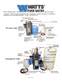
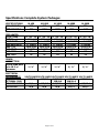
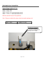
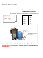
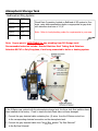
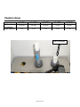
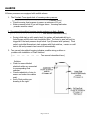
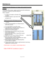
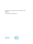
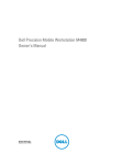
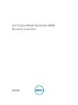
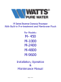
M Series Reverse Osmosis Processor
With Built-in Pre-treatment and Membrane Flush
For Models:
M- 450
M-1000
M-2400
M-4800
M-9600
Installation, Operation
&
Maintenance Manual
Page 1 of 18
Before installing and/or operating Watts M-Series Reverse Osmosis system, read this manual
completely. Keep this manual available for future reference. Further information is available by
contacting your local Watts distributor. Phone: (623)505-1511
Pressure Tank
Atmospheric Tank
Page 2 of 18
TABLE OF CONTENTS
Specifications
Specifications Chart ……………………………… 4
Installation
Membrane installation ………………………………. 5
Inlet Connection ………………………………………. 6
Permeate Line Connection …………………..……. 7
Pressure Tank Connection ……………………..…. 8
Atmospheric Storage Tank ………………………… 9
Plumb to Drain ………………………………………. 10
Operation
Start Up …………………………………………………..11
Alarms …………………………………………………….12
Maintenance
Quarterly Maintenance ………………………………13
Annual Maintenance ………………………………….14
Warranty
Warranty ………………………………………………….15
Glossary of Terms …………………………..………. 17
Page 3 of 18
Specifications Complete System Packages
SPECIFICATIONS
DRY WEIGHT lbs.
M-450
300
M-1000
310
M-2400
350
M-4800
650
M-9600
750
WET WEIGHT lbs
550
1700
1750
4000
4100
FEED WATER
COLD/Temp
HOT/ Temp
FLOW RATE
MAX.HARDNESS
MAX. TDS
MAX. IRON
MAX. PSIG
MIM. PSIG
DRAIN
CONNECTION
FLOOR SINK MIM.
w/in 10 ft of
processor
ELECTRICAL
REQUIRMENTS
RO PROCESSOR
OPTIONAL 220V
DELIVERY PUMP
KDF FILTER
½”/35°-70° ½”/35°-70° ½”/35°-70° ¾”/35°-70°
½”/70°-140° ½”/70°-140° ½”/70°-140° ¾”/70°-140°
2 GPM
17 Grains
2500 PPM
0.1 MGL
80
25
4 GPM
17 Grains
2500 PPM
0.1 MGL
80
25
8 GPM
17 Grains
2500 PPM
0.1 MGL
80
25
12 GPM
17 Grains
2500 PPM
0.1 MGL
80
25
1/ ¼”
1/ ¼”
1/ ¼”
1/ ¼”
¾”/35°-70°
¾”/70°-140°
24 GPM
17 Grains
2500 PPM
0.1 MGL
80
25
1/ ¼”
VOLTS/AMPSVOLTS/AMPSVOLTS/AMPS VOLTS/AMPS VOLTS/AMPS
115/7.2
115/7.2
115/11.0
115/23
220/11.5
220/8.8
220/11.5
N/A
115/8.8
115/12.4
115/12.4
115/12.4
N/A
N/A
N/A
115/2
115/2
Page 4 of 18
Membrane Installation
Note: All Membrane Vessels are
clearly marked with flow direction.
Membrane “Brine Seal” is always
facing the water entry to Vessel.
Brine Seal
Membrane
Membrane
Vessel
Flow
Direction
Marking
Page 5 of 18
Inlet Connection
HOT and/or COLD FEED WATER
CONNECTION
Hard plumb Hot and/or Cold water
connections into Blending Valve
using (L) Copper Pipe. Refer to table
below. Valve is marked with HOT
and Cold connections.
Recommend installing Ball Valves
just prior to the Blending Valve.
NOTE: Use only
Teflon tape on all
threaded pipe.
RO
FEED WATER
MIN/MAX
PSIG
PIPE
SIZE
FLOW
RATE
M-450
25/80 psig ½”
2 GPM
M-100
25/80 psig ½”
4 GPM
M-2400
25/80 psig ½”
8 GPM
M-4800
25/80 psig 1”
12 GPM
M-9600
25/80 psig 1 ¼”
24 GPM
Page 6 of 18
Permeate Line Connection
Required fittings for Bulkhead & Tank
M450 ½” MPT x 3/8C .
M1000 ½” MPT x 3/8C
M2400 ½” MPT x ½”C
M4800 ¾” MPT x ¾” Female Slip Schedule 40 PVC
M9600 1” MPT x 1” Female Slip Schedule 40 PVC
Ball Valve used with Pressure Tank applications.
Note: Fittings are included with systems ordered as complete packages only!
M-450 – M2400
M4800 – M9600
½” Tubing or PVC pipe
¾” PVC Schedule 40 pipe
Permeate Line Connection
The M Series permeate
connection is on the bulkhead
labeled “OUT TO TANK”
Page 7 of 18
Pressure Tank Connection
Recommended tubing size
From bulkhead on unit to tank .
Note: Fittings are included with Systems ordered as complete packages only!
M450 - M2400
Flexible poly tubing acceptable.
M4800 – M9600
Schedule 80 PVC required.
M-450
3/8”
M-1000
3/8”
M-2400
3/8”
M-4800
¾”
M-9600
¾”
Note: Copper pipe is UNSUITABLE for any plumbing from RO Storage Tank!
Recommended materials include: Braided Stainless Steel Tubing, Hard Stainless.
Schedule 80 PVC or Poly Propylene is acceptable, if not being connected to boiler or
heating system.
Page 8 of 18
Atmospheric Storage Tank
Bulkhead & Fitting Systems
M-450
3/8”
M-1000
3/8”
M-2400
3/8”
Plumb Drain Connection located on Bulkhead of RO system to floor
drain, using table specifications below or appropriate air gap drain
with minimum drain size of 1 1/4”.
M-4800
3/4 “
Note: Refer to local plumbing codes for requirements in your area.
M-9600
3/4”
Note: Copper pipe is UNSUITABLE for any plumbing from RO Storage tank!
Recommended materials include: Braided Stainless Steel Tubing, Hard Stainless.
Schedule 80 PVC or Poly Propylene, if not being connected to boiler or heating system.
If the M-Series was ordered with the atmospheric storage tank, the three tank float switches have
been installed at the factory. Check to insure the tank floats have not been damaged.
1. Connect the gray electrical cable containing four (4) wires from the M-Series control box
to the corresponding electrical connection on the atmospheric tank.
2. Connect the gray electrical cable from Control
Box, labeled “By-Pass Solenoid”
Page 9 of 18
to the By-Pass Solenoid.
Plumb to Drain
Bulkhead
Connection
Drain Size Min.
M-450
M-1000
M-2400
M-4800
M-9600
1/2” Poly
1/2” Poly
1/2” Poly
½” PVC
¾” PVC
1 ¼”
1 ¼”
1 ¼’
1 ¼’
1 ¼”
Drain Connection
Page 10 of 18
Start Up
ü Ensure power switch (located on top of control Box).
2
3
(#1) is in the OFF position.
4
ü Plug the unit into an appropriate power supply.
ü If installing a pressure Tank system, open the Ball
6
Valve (#2) on the Bulkhead.
7
ü Turn the Blending Valve to coldest setting [90°]. (#3)
ü Fully open the Concentrate Needle (#4) Valve by
turning it counter clockwise.
ü Fully close Recirculate Needle Valve (#5) by turning it
clockwise.
ü Turn the incoming water supply on the RO processor
to the “ON” position.
ü Turn the Power Switch (#1) to “ON” position.
5
• The Water inlet solenoid valve will open.
• There will be a 5 second delay before the pump
starts.
• The system may cycle on and off automatically
during initial start up as air is purged from
system.
• Allow the unit to run for 5 minutes while excess
air is being purged from system.
ü Close the Concentrate Needle Valve (#4) until the
Feed Pressure Gauge(#6) reaches a max. of 150 psig.
ü Open the Recirculation Needle Valve (#5) until the
unit Feed Pressure Gauge (#6) drops to 140 psig.
ü Close the Concentrate Needle Valve (#4) until 150 psig is again achieved on the Pump Feed
Pressure Gauge (#6).
4
1
0
Repeat underlined sequence until both flow meters read equal flows and feed pressure gauge reads
150 psi. At this point the RO processor is operating at its maximum efficiency potential.
If using a Pressure Tank, system will continue to operate until Tank Pressure Gauge reads 60 psig or
Float Tank, upper float switch is triggered by the water level.
NOTE: At no time should the Concentrate
Valve ever be completely closed. RO system
must have some water running to the drain
during production or RO water.
Page 11 of 18
NOTE: DO NOT operate over 150
psi, as this will damage membrane.
The back pressure will read less
than 150 psi.
ALARMS
M-Series processors are equipped with audible alarms.
1. The Constant Tone signals lack of incoming water pressure.
(-------------------------------------------------------- Constant Tone)
• Check incoming feed pressure to ensure a minimum of 20 psi.
• Water pressure below 20 psi will trigger alarm. Incoming feed water
pressure must be raised.
2. One second intermittent beeping signals systems is in Auto –Bypass.
(-- -- -- -- -- -- -- -- -- -- -- -- -- -- One second intermittent tone).
•
During initial start up with empty tank, the system will automatically be in
Auto-Bypass until the tank has completely filled. The Auto by pass will only be
triggered if the tank pressure drops below 5 psi (Pressure tank systems). Float
switch controlled Atmospheric tank systems with float switches, remain on until
tank is full and processor has turned off automatically.
3. Two second intermittent beeping indicates possible wiring problem or
problem with installation of Float Switches.
(---- ---- ---- ---- ---- ---- Two second intermittent tone.)
•
•
•
Solution:
Check to ensure labeled
electrical cables are connected
to corresponding float
switches.
Check conductivity of wire to
ensure no broken wire cables
exist.
Verify Float position per
drawing to the right.
Page 12 of 18
Maintenance
Quarterly Preventive Maintenance for Systems with complete Pre and Post
treatment.
The M-Series RO processor requires quarterly preventive maintenance
consisting of replacing (3) pre-filters and post
Filters if supplied.
1. Pre-filters are located on left side of RO
processor.
2. Post filters located on right side of RO
processor unit.
Quarterly preventive maintenance procedure.
1. Turn incoming feed water off while unit is
running.
2. System will automatically turn off due to lack of
feed water pressure.
3. Turn Power Switch to the OFF position.
4. Close Ball Valve on Permeate Line Connection on
Bulkhead (Pressure Tank Systems).
5. Unplug unit from Power Supply.
6. Place bucket under pre-filters to catch the water
from the filter housings.
7. Using supplied filter wrench, loosen filter housing
starting on the left.
8. Replace with new 5 micron Sediment Filter and
replace filter
housing using wrench to tighten securely.
(O-rings and Bowls need to be lubricated with a water
soluble lubricant such as KY Jelly).
9. Follow the above sequence with remaining filters.
and Post Filters if supplied.
10. Replace Calcite Feeder located on right hand side of unit using
supplied filter housing wrench.
(Calcite feeder is only needed on units feeding boilers).
Follow “START UP” procedures on page 11
Page 13 of 18
Annual Preventive Maintenance
Perform quarterly preventive maintenance.
Include replacement of O-Rings.
Replace RO membrane by
loosen retaining clamp at top
of stainless steel membrane
vessel .
Carefully pry loose PVC end
cap from stainless steel
vessel.
Pull membrane from vessel using pliers i
necessary and discard. Take note of
location of black BRINE SEAL located
approx. 1/2” from one end of membrane,
so the new membrane will be installed in
the proper direction.
Note: If using pliers to remove NEW membrane for any reason, protect end of membrane with
cloth, to prevent teeth marks which could result in leaks.
Page 14 of 18
Annual Preventive Maintenance
Lubricate O-Rings on both ends of
the Membrane and PVC Vessel Cap
with K-Y Jelly or other water soluble
lubricant.
*Vaseline or other petroleum based
lubricants will damage rubber o-ring
and cause leaks.
Insert new membrane into vessel with
the Brine Seal on same position as the
old one just removed.
Replace PVC end cap
and tighten clamp
evenly.
Page 15 of 18
WARRANTY
WHAT YOUR WARRANTY COVERS:
If any part of your Premier Water Treatment Device is defective in workmanship (excluding replacement filter elements), return the
unit within 1 year of date of original purchase. PREMIER will repair or, at PREMIER’S option, replace it at no charge.
HOW TO OBTAIN WARRANTY SERVICE:
Contact WATTS PREMIER’S customer service department (1-800-752-5582) to obtain a Return Goods Authorization Number (RGA#).
Model and Serial Number are required for obtaining an RGA #. For warranty service, ship your water treatment device wit h the RGA #
printed on the Shipping Label to PREMIER, freight and insurance prepaid, with proof of original purchase date. PREMIER will repair or
replace the water treatment device and ship it back to you prepaid.
WHAT YOUR WARRANTY DOES NOT COVER:
This warranty does not cover defects resulting from improper installation, customer abuse, misuse, misapplication, improper
maintenance, neglect, alteration, accidents, casualties, fire, flood, freezing, heat, environmental factors or acts of nature.
This warranty will be voided if defects occur due to failure to observe the following conditions:
1. The water treatment device must be hooked up to a potable municipal water supply.
2. The pH of incoming water must not be lower than 6.0 or higher than 8.5.
3. The incoming water pressure must be between 25 psi and 80 psi. If water pressure exceeds 80 psi a pressure regulator
must be
installed.
4. Incoming water temperature cannot exceed 100° F (40° C).
This warranty does not cover any equipment that has been relocated from the site of its original installation.
This warranty does not cover equipment that is installed outside North America.
LIMITATIONS AND EXCLUSIONS:
PREMIER WILL NOT BE RESPONSIBLE FOR ANY IMPLIED WARRANTIES, INCLUDING THOSE OF MERCHANTABILITY AND FITNESS
FOR A PARTICULAR PURPOSE.
PREMIER WILL NOT BE RESPONSIBLE FOR ANY INCIDENTAL OR CONSEQUENTIAL DAMAGES, INCLUDING TRAVEL EXPENSES,
TELEPHONE CHARGES, LOSS OF REVENUE, LOSS OF TIME, INCONVENIENCE, LOSS OF USE OF THE EQUIPMENT, AND DAMAGES
CAUSED BY THE EQUIPMENT AND ITS FAILURE TO FUCTION PROPERLY.
THIS WARRANTY SETS FORTH ALL OF PREMIER’S RESPONSIBILITIES REGARDING THIS EQUIPMENT.
OTHER CONDITIONS: IF PREMIER chooses to replace the equipment, PREMIER may replace it with reconditioned equipment. Parts
used in repairing or replacing the equipment will be warranted for 90 days from the date the equipment is returned to you or for the
remainder of the original warranty period, whichever is longer. This warranty is not assignable or transferable.
YOUR RIGHTS UNDER STATE LAW:
Some states do not allow limitations on how long an implied warranty lasts and some states do not allow the exclusion or limitation of
incidental or consequential damages, so the above limitations or exclusions may not apply to you. This warranty gives you specific
legal rights. You may have other legal rights, which vary from state to state.
Page 16 of 18
GLOSSARY OF TERMS
Atmospheric tank: A storage container requiring additional delivery system to distribute stored water.
Typically constructed of polyurethane or stainless steel. Used in situations where greater storage
capacity is needed than offered by conventional pressure tanks.
Auto By-Pass: A feature that allows tap water to be delivered to downstream demands in the event the RO
processor is unable to meet demand.
Brine Seal: A black “O-ring type seal located on one end of membrane that seals the membrane to the vessel
preventing cross contamination of process water and feed-water.
Calcite Feeder: Calcite is a naturally occurring mineral used to raise the Total Dissolved Solids (TDS) in the
water to promote conductivity in the final product water. Used in situations where conductivity is
needed for proper equipment function i.e. conductivity probes.
Carbon Block: Acid washed carbon is used to absorb VOC’s (Volatile Organic Chemicals) such as herbicides,
pesticides and chlorine, which will damage RO membranes.
Concentrate needle valve: A needle valve located on the right side flow meter that controls the concentrate
(drain water) water flow to the drain.
Concentrate: Water being rinsed to drain after it has been rejected by the membrane.
Concentrate Line: Tubing or pipe used to transport concentrated waste water to a suitable drain.
Feed pressure: Referring to the water pressure being supplied to the RO processor before it has entered the
pre-filter. Raw water.
Feed pressure gauge: The upper most gauge on the control panel that indicates the water pressure the
membrane is receiving.
Flow meter: A meter that reads water flow in gallons/liters per minute
GPM: Gallons per minute
GPD: Gallons per day
Hardness: Total quantity of CaCO3 (Calcium/magnesium) present in water.
1 gr. = 17.1 TDS in ppm per U.S. gallon
Iron: A naturally occurring mineral that has detrimental effects on a membranes ability to produce water.
Reduced by ion exchange (water softening) or KDF media.
KDF Media Filter: A proprietary blend of metals and other substances that help reduce Iron and CaC03
(hardness). Used as pretreatment on some models of high production RO systems.
L Copper pipe: A high grade of copper pipe that will withstand water temperatures up to 160 degrees
Fahrenheit.
Membrane: A thin sheet or surface film, either natural or man-made, of microporus structure that performs as
an efficient filter of particles down to the size rang of chemical molecules and ions. Such membranes
are termed “semi-permeable” because some substances will pass through but others will not. Usually
small ions, water, solvents, gases, and other very small molecules can pass through a membrane, but
other ions and macromolecules such as proteins and colloids are barred form passage. Membranes are
used in reverse osmosis.
Page 17 of 18
GLOSSARY OF TERMS (Continued)
Permeate: That portion of the feed water which passes through the membrane to become product water.
Permeate Line: Tubing or pipe used to transport purified (RO processed) water from processor to the storage
tank.
Pressure tank: A water storage device using a pressurized bladder that provides delivery pressure to down
stream uses.
Purge: The act of flushing out. A term to describe the purging of entrained air in a system
Recirculation Valve: A needle control valve used to blend concentrate water past the membrane again to
scavenge water molecules.
Recirculation Ratio: The ratio in which concentrate water is reticulated past the membrane in order to
osmoisize more water molecules and reduce the wasted ratio of water. Typical recirculation ratio is 1:1
(1 gallon permeate: 1 gallon concentrate
Reverse Osmosis: A water treatment process that removes undesirable material from water by using
pressure to force the water molecules through a semi-permeable membrane. This process is called
“reverse” osmosis because the pressure forces the water to flow in the reveres direction (from the
concentrated solution to the dilute solution) to the flow direction (from the dilute to the concentrated)
in the process of natural osmosis. RO removes ionized salts, colloids, and organic molecules down to a
molecular weigh of 100. May be called hyper-filtration.
RO: Reverse Osmosis
RO Processor: The system main stand, that consists of the main frame, pump, electrical controls, flow meters
and pressure gauges. A term used to signify a specific piece of the overall system.
Sediment Filter: A filter used to trap and reduce rust, dirt and sand. Typically made from spun poly.
TDS: Total Dissolved Solids, the total weight of dissolved matter present in water that does not constitute pure
water molecules. Measured in the form of resistively and or conductivity equated into TDS in ppm
(parts per million per 1 U.S. gallon)
VOC: Volatile Organic Chemicals, synthetic organic chemicals that turn into vapor at relatively
Zero Soft Water: Water produced by Reverse Osmosis measuring less than 1/0 grain per U.S. gallon (17.1
ppm or 17.1 mg/L) as calcium carbonate.
Page 18 of 18