1
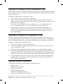
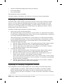
ESP-2 Multi-Interface Serial Hub
Installation Guide
590-298-001C
June 2003
Contents
Introduction . . . . . . . . . . . . . . . . . . . . . . . . . . . . . . . . . . . . . . . . . . . 1
What You Get . . . . . . . . . . . . . . . . . . . . . . . . . . . . . . . . . . . . . . 1
Hardware . . . . . . . . . . . . . . . . . . . . . . . . . . . . . . . . . . . . . . . . . . . . . 1
Interfaces . . . . . . . . . . . . . . . . . . . . . . . . . . . . . . . . . . . . . . . . . . 2
Pin Assignments . . . . . . . . . . . . . . . . . . . . . . . . . . . . . . . . . . . . . 3
Electrical . . . . . . . . . . . . . . . . . . . . . . . . . . . . . . . . . . . . . . . . . . 3
Technical Specifications . . . . . . . . . . . . . . . . . . . . . . . . . . . . . . 4
Changing the Interface Settings . . . . . . . . . . . . . . . . . . . . . . . . . 4
Installing the Unit . . . . . . . . . . . . . . . . . . . . . . . . . . . . . . . . . . . . 5
Startup Sequence . . . . . . . . . . . . . . . . . . . . . . . . . . . . . . . . . . . . 6
Reinitializing and Resetting the Unit . . . . . . . . . . . . . . . . . . . . . 6
Installing and Configuring Drivers . . . . . . . . . . . . . . . . . . . . . . . . . 7
Windows 2000 and Windows XP . . . . . . . . . . . . . . . . . . . . . . . 8
Windows NT 4.0 . . . . . . . . . . . . . . . . . . . . . . . . . . . . . . . . . . . . 8
Open Server . . . . . . . . . . . . . . . . . . . . . . . . . . . . . . . . . . . . . . . . 9
UnixWare . . . . . . . . . . . . . . . . . . . . . . . . . . . . . . . . . . . . . . . . . 10
Linux . . . . . . . . . . . . . . . . . . . . . . . . . . . . . . . . . . . . . . . . . . . . 11
AIX . . . . . . . . . . . . . . . . . . . . . . . . . . . . . . . . . . . . . . . . . . . . . . 12
Using the Web Interface . . . . . . . . . . . . . . . . . . . . . . . . . . . . . . . . 13
About the Web Interface Window . . . . . . . . . . . . . . . . . . . . . . 13
Displaying or Changing Network Configuration Values . . . . . 14
Displaying or Changing Port Configuration Values . . . . . . . . 14
Displaying Hardware Information . . . . . . . . . . . . . . . . . . . . . . 14
Displaying or Updating FLASH Memory . . . . . . . . . . . . . . . . 15
Displaying or Changing Configurable Features . . . . . . . . . . . . 15
Displaying General Statistics . . . . . . . . . . . . . . . . . . . . . . . . . . 16
Displaying Port Statistics . . . . . . . . . . . . . . . . . . . . . . . . . . . . . 16
Displaying Connected Servers Information . . . . . . . . . . . . . . . 17
Rebooting the Unit . . . . . . . . . . . . . . . . . . . . . . . . . . . . . . . . . . 17
Reinitializing the Unit . . . . . . . . . . . . . . . . . . . . . . . . . . . . . . . 17
Changing the Password . . . . . . . . . . . . . . . . . . . . . . . . . . . . . . 18
Introduction
The Equinox Ethernet Serial Provider 2-port Multi-Interface (ESP-2 MI) Serial Hub contains an
autosensing 10/100 Ethernet connection and two serial multi-interface ports.
The ESP-2 MI is supported under Windows 2000, Windows XP, Windows NT 4.0, OpenServer
5.0.5a or higher, UnixWare 7.0.1a or higher, Linux and AIX 4.3 and 5.1.
Software configurable parameters are downloaded to the device via the Ethernet connection. The
ESP-2 MI is configured using appropriate operating system drivers, and managed using EquiView
Plus, running on any Microsoft Windows host, or espdiag and espcfg for OpenServer, UnixWare,
Linux or AIX. Certain configuration values are set during driver installation.
The ESP-2 MI can also be managed by using a standard web browser to access the embedded
web server interface. Any browser that supports frames may be used, and the web interface is
accessible from any system, regardless of operating system type.
This Installation Guide describes how to:
•
•
•
Install the hardware
Initiate driver installation
Use the web interface
What You Get
The ESP-2 MI kit contains the items listed in Table 1.
Part No.
Description
520-312
ESP-2 MI Unit
590-298
Installation Guide (this document)
990458 (AM)
- or 990460 (EU)
External Power Supply with attached PS-to-Barrel Connector
650185
Equinox SuperSerial Software CD
Table 1. ESP-2 MI Kit Contents
An Industrial Mounting Kit (790226) is available for installing the ESP-2 MI on a DIN rail.
Hardware
Figure 1 shows the front of the ESP-2 MI.
Figure 1. ESP-2 MI Front View
1
Equinox ESP-2 MI Serial Hub Installation Guide
The lower left area of the front panel contains two electrical connectors. You may use one of
these, but not both. For more information, see Electrical.
The LAN connector is used with a 10BaseT or 100BaseT LAN interface cable. A CAT 5 cable
is required for 100BaseT operation.
The two PORTS connectors are standard DB-9 DTE ports in RS-232 mode. The unit ships
with RS-232 mode enabled for both ports.
Table 2 describes the LEDs and buttons on the front panel.
Item
Description
POWER
The POWER LED is lit when the ESP is connected to a power source
ON LINE
The ON LINE LED is lit (not blinking) when the ESP self-test and initialization
procedures have completed successfully
10
The 10 LED is lit when the ESP is connected to a 10 Mbps LAN, and the 100
LED blinks when traffic is present
100
The 100 LED is lit when the ESP is connected to a 100 Mbps LAN, and the 10
LED blinks when traffic is present
RESET
Pushing the RESET button reboots the ESP
INIT
Pushing the INIT button restores the ESP to factory defaults
Table 2. LEDs and Buttons
For information about using the RESET and INIT buttons, see Reinitializing and Resetting.
Interfaces
Each port supports the standard RS-232 DTE serial signals via a male DB-9 connector, with the
exception of RI. Each port can be configured independently to support the following interfaces:
•
•
•
RS-232 DTE signaling (default)
RS-422 signaling
RS-485 2-wire half duplex (HD) signaling
Internal jumpers are used to select the signaling for each port. For more information, see
Changing the Interface Settings.
A software configurable option lets you enable/disable a one port option. When enabled, only
port 1 is used. This option can be set during driver installation.
When RS-485 HD signalling is set via internal jumpers, software-configurable modes can
be set to control the enabling/disabling of the transmitter and receiver. The choices are RTS
(Request to Send) control mode or ADDC (Automatic Data Detection Control) mode.
•
•
In RTS mode, the transmitter is enabled and the receiver is disabled when RTS is true.
The transmitter is disabled and the receiver is enabled when RTS is false.
In ADDC mode, the transmitter is enabled and the receiver is disabled when a space
(zero) bit is sent. The transmitter is disabled and the receiver is enabled when a mark
(one) bit is set. This mode allows rapid turnaround and release of the data pair.
The RS-485 transfer mode can be specified during driver installation or through the web interface.
2
Equinox ESP-2 MI Serial Hub Installation Guide
When RS-422 signalling is set, the receiver and transmitter are always enabled.
Pin Assignments
Table 3 lists the pin assignments for the ports’ DB-9 connectors. This information is also
provided on a label on the bottom of the unit.
Pin
RS-232
RS-422
RXD(+)
RS-485
1
DCD
N/C
2
RxD
RXD(-)
N/C
3
TxD
TXD(+)
Data(+)
4
DTR
TXD(-)
Data(-)
5
GND
GND
GND
6
DSR
N/C
N/C
7
RTS
N/C
N/C
8
CTS
N/C
N/C
9
N/C
N/C
N/C
Not supported: RI, RS-422 RTS and CTS differential control signals
Table 3. Serial Port Pin Assignments
NOTE: Unused pins (labeled N/C) should not have wires attached to them. Floating wires could
cause unbalanced noise, shorten overall distances and degrade performance.
Table 4 lists the pin assignments for the RJ-45 shielded Ethernet connector.
Pin
Signal
1
Transmit Data +
2
Transmit Data -
3
Receive Data +
4
*
5
*
6
Receive Data -
7
*
8
*
* These pins are usually connected in a standard Ethernet CAT 5 cable. There is special termination
for those signals in the interface to eliminate any problems if they are connected.
Table 4. Ethernet Connector Pin Assignments
Electrical
The ESP-2 MI has two electrical power connectors on the front of the unit. These connectors
are labeled POWER 9-30VDC 4W. You may use either one of these connectors, but not both.
•
3
The unit ships with an external power adaptor. This adaptor includes a barrel plug that is
inserted into the leftmost power connector on the unit’s front panel.
Equinox ESP-2 MI Serial Hub Installation Guide
•
The unit also contains a 3-pin screw terminal block connector which provides connection
for a 9 VDC to 30 VDC power source. The location of the positive, ground and negative
pins are screened on the front panel.
Surge protection is provided for each serial port up to 15,000 volts ESD.
Technical Specifications
Table 5 lists the ESP-2 MI technical specifications.
Specification
Operating Range
Dimensions
4.75”W x 4.38D x 1.62”H
Temperature
0˚-50˚C (32˚-122˚F)
Humidity
10-90% non-condensing
Power
9-30 VDC at less than 4W
Table 5. ESP-2 MI Operating Specifications
Changing the Interface Settings
The factory default interface setting for both ports is RS-232. If you want the ports to use this
interface, you may skip this section.
To enable the RS-422 or RS-485 interface for one or both serial ports (or, if you previously enabled
one of these interfaces and now want to enable another interface), use the following procedure.
You will need a Phillips screwdriver. Proper electrostatic discharge (ESD) protection should
be used at all times.
1.
2.
3.
4.
5.
4
Place the ESP-2 MI unit on a flat surface.
Use the Phillips screwdriver to loosen the two screws on either side of the unit (total of
four screws). Remove the screws.
Lift the cover up and off the unit. Use Figure 2 as a guide to locate the two ganged
headers on the printed circuit board (PCB).
Each ganged header contains four columns of five pins. The jumper for each port is
ganged and covers two columns.
•
Installing the jumper over the two rightmost pin columns enables the RS-232 interface.
•
Installing the jumper over the two middle pin columns enables the RS-422 interface.
•
Installing the jumper over the two leftmost pin columns enables the RS-485 2-wire
HD interface.
To change a port’s interface, lift the jumper off its current interface setting and place it
on the columns corresponding to the desired interface setting. The interface settings are
screened on the PCB.
If you are enabling the RS-422 or the RS-485HD interface on a port, you may also
enable/disable 100 ohm termination of the differential receive signal pair on that port.
This termination is enabled by placing a jumper on the 2 pins adjacent to the ganged
jumper for the port; see the location noted in Figure 2. Termination is enabled by factory
default, that is, the jumper covers both pins for each port.
Equinox ESP-2 MI Serial Hub Installation Guide
6.
7.
Figure 2. Jumper Locations and Settings
This termination is typically used in RS-485 environments when the device is the first or
last on a multi-drop line for a 2-wire configuration. This termination should always be set
when the unit is set for RS-422, as this is point-to-point configuration.
If your configuration includes supplying your own external termination, the termination on
the ESP-2 MI should not be used.
To disable termination, remove the jumper entirely.
When the RS-485HD interface is enabled in hardware, you will be able to select the
transmitter/receiver mode during startup. For more information on these softwareconfigurable options, see Interfaces.
Replace the cover on the unit and reinstall the four screws.
Installing the Unit
The ESP-2 MI can be installed on a table, on a DIN rail or on a wall.
WARNING: The power outlet should be installed near the equipment and should be
easily accessible.
The ESP-2 MI supports hot swapping, that is, you may replace an existing ESP-2 MI with a
similarly configured unit without affecting the server or having to reconfigure the ports.
5
Equinox ESP-2 MI Serial Hub Installation Guide
Installing on a Table
The unit ships ready to use in a tabletop environment. This includes four rubber feet on
the bottom of the unit. At a later time, if you want to move the unit to a DIN rail or a wall
installation, you can remove the rubber feet. Grasp the bottom of each foot and gently pull it
down and out of the hole.
Installing on a DIN Rail
Equinox offers an Industrial Mounting Kit, part number 790226, containing hardware and
instructions for mounting an ESP-2 MI on a DIN rail.
Installing on a Wall
The ESP-2 MI unit contains two sets of mounting flanges for flexibility in mounting options
on a wall or other vertical surface. You will need to provide the appropriate number of
screws and washers.
•
•
You may install the unit with the bottom (that is, the side containing the large label)
against the wall, using the four flanges on the bottom of the unit.
The unit ships with rubber feet installed in these flanges for tabletop installation. Remove
them by grasping the bottom of each foot and gently pulling it down and out of the hole.
Then, use your screws and washers to attach the unit to the wall.
You may install the unit with the back against the wall, using the two flanges on the back
of the unit. In this case, you can remove the four rubber feet on the bottom of the unit or
leave them installed. Use your screws and washers to attach the unit to the wall.
With either of the above installations, you may orient the unit to best fit your configuration.
Startup Sequence
1.
The MAC address is printed on a label on the bottom of the unit. This address will be used
as a Unit ID to distinguish different ESP units on the network. Record the MAC address.
00 - 80 - 7D - _____ - _____ - _____
2.
3.
4.
5.
Attach a 10BaseT or 100BaseT LAN interface cable to the LAN connector. A CAT 5
cable is required for 100BaseT operation.
Attach the electrical power connector(s) to the appropriate connector on the front of the unit.
Windows systems only: Install or upgrade to EquiView Plus version 5.2 or higher from
the Equinox SuperSerial Software CD.
Install the ESP driver for your target operating system; see Installing and Configuring Drivers.
Reinitializing and Resetting the Unit
The information in this section is not a normal part of the startup sequence; however, it is
provided for reference if the ESP-2 MI must be reinitialized or reset.
6
Equinox ESP-2 MI Serial Hub Installation Guide
The INIT button on the front panel can be used to remove configured information from an ESP
unit. The ESP stores nonvolatile data such as SNMP community name, system contact and IP
address in the EEPROM. This information can be erased by pressing the INIT button.
NOTE: Pressing the INIT button will interrupt ESP operation and cause reinitialization to occur.
When the INIT button is first pressed, the ONLINE LED will begin to blink to confirm that you
have pressed the INIT button. As the INIT button remains pressed, the ONLINE LED will blink
at a faster rate. After approximately 12 seconds, the ONLINE LED will turn off. At this point, all
nonvolatile information will be reset to the factory defaults and the unit will immediately reboot.
The RESET button on the front panel can be used to reset the ESP. Pushing this button will
cause an immediate reboot.
You may also reinitialize and reset the unit via the web interface.
Installing and Configuring Drivers
During the automated driver installation and configuration process, you may enable or disable
the one port option. If you enable the one port option, all further installation and configuration
operations will only affect port 1. Port 2 will be unusable and will not be shown in the
configuration operations.
As described in Changing the Interface Settings, the port interface type (RS-232, RS-422 or
RS-485) is selected by jumpers inside the unit. During software installation and configuration,
the current settings for each port are displayed (if you have the one port option enabled, the
display includes only port 1).
If a port’s hardware jumpers are set for RS-485, the display will allow you to choose the
transmitter/receiver mode: RTS or ADDC. (You may also change the RS-485 transfer mode via
the web interface.) See Interfaces for more information. If a port’s hardware jumpers are set for
RS-232 or RS-422, you must change the jumper positions in the hardware to change the interface.
If you want to change the configuration after the drivers are installed, you may upgrade the
drivers to enable or disable the one port option without rebooting the unit. For ports that are
hardware configured for the RS-485 interface, you may also change the transmitter/receiver
mode. To access these options, click the Configure button on the Properties page. See Using the
Web Interface for information about values you can change and display.
The following sections contain instructions for installing the ESP drivers. The ESP is supported
under Windows 2000, Windows XP, Windows NT 4.0, OpenServer 5.0.5a or higher, UnixWare
7.0.1a or higher, Linux and AIX 4.3 and 5.1.
Windows 2000 and Windows XP
To install the Windows 2000/XP ESP driver, you must first run SETUP.EXE from the
Windows 2000/XP ESP driver diskette that is made using the Equinox SuperSerial CD-ROM.
SETUP.EXE will install the necessary Device Manager files for the ESP. Insert the diskette into
your A: drive, set your default drive to A: and run SETUP.
The Windows 2000 ESP driver is installed when you install the first ESP.
7
Equinox ESP-2 MI Serial Hub Installation Guide
1.
2.
3.
Navigate to Settings - Control Panel - Add/Remove New Hardware.
From the Add/Remove Hardware Wizard, select Add/troubleshoot a device.
Windows 2000 will search for new Plug and Play hardware on your computer. ESP
devices are network-attached and are not located by the Add New Hardware Wizard. A
list of devices that can be installed will be displayed. Select Add a new device.
4. From the Find New Hardware page, select No, I want to select the hardware from a list.
5. A list of hardware types will be displayed. Select Multi-port serial adapters.
6. Windows 2000 will ask you to select a device driver. Highlight Equinox Systems Inc., select
Equinox Ethernet Serial Provider / Have Disk and point the Wizard to your A: drive.
7. From the Select a Device Driver page, again select Equinox Ethernet Serial Provider.
8. The Wizard will locate an ESP on your server’s local subnet and display information
about that ESP. If your ESP does not yet have an IP address, you must enter the IP
address, then click Next.
9. The Wizard will display the ESP configuration for final verification. If the IP address you
assigned is correct, click Next.
10. The Wizard will now copy files from the Windows 2000 ESP driver diskette. During this
process, the Equinox ESP driver file is examined for a Microsoft digital signature. If the
ESP driver is not signed, a warning message is displayed. To continue the installation,
read the warning and then click Yes.
If you click No, the installation will terminate and the ESP will not be installed on your server.
11. Once all files are copied, click Finish.
Your ESP is now installed. Windows 2000 will now install the ESP serial ports.
Windows NT 4.0
1.
2.
3.
4.
Navigate to Settings - Control Panel - Network to display the Network Control Panel.
Select the Services tab. Click Add to install the ESP driver for Windows NT 4.0.
The Control Panel will generate a list of standard Network Services. The Equinox ESP
Service is a new network service. Click the Have Disk button.
The Control panel will ask you to enter the pathname for the disk that contains the ESP
Service installation files.
a) If you are installing from diskette, enter the drive letter of the diskette drive.
b) If you are installing from the Equinox SuperSerial CD, enter the pathname D:
\DRIVERS\ESP\NT, where D: is your CD-ROM drive letter.
c) If you have stored the driver on the NT system or on a network drive, enter the full
pathname for the location of the Equinox ESP Service.
The Control Panel will copy files from the specified path to the required NT system
directories. Once the copy is complete and the driver is installed, the Control Panel will
automatically start the Equinox ESP Service. It will also start the ESP Installation Wizard
and attempt to locate ESP units on all local subnets.
Using the Installation Wizard, you can:
•
•
8
Discover and install ESP units on local or remote subnets
Configure ESP units and assign COM port numbers
Equinox ESP-2 MI Serial Hub Installation Guide
•
Replace an ESP unit on a local or remote subnet
See the online help in the ESP Installation Wizard for more information.
OpenServer
The following sections contain procedures for installing the ESP driver on an Open Server
release 5.0.5a or higher system.
Installing Directly from CD-ROM
1.
Mount the CD-ROM volume using the following command:
mount -f ISO9660,filemode=444 <device> <mount_point>
For example, the following command mounts a CD-ROM on drive 1 to /mnt:
mount -f ISO9660,filemode=444 /dev/cd1 /mnt
2.
3.
4.
Install the driver using the “custom” utility with media image VOL.000.000.
When custom prompts for Media Device, select Media Images.
When custom prompts for Image Directory, specify:
/mnt/DRIVERS/ESP/SCO
5.
Follow the instructions for custom contained in the file:
/mnt/DRIVERS/ESP/SCO/README.
Creating OpenServer ESP Installation Diskettes on OpenServer
1.
2.
Be sure the mkdev cdrom command has been run.
Mount the CD-ROM volume using the following command:
mount -f ISO9660,lower <device> <mount_point>
For example, the following command mounts a CD-ROM on drive 0 to /mnt:
mount -f ISO9660,lower /dev/cd0 /mnt
3.
Run the following commands:
cd /mnt [or other mount point]
./makeunix.sh
4.
5.
Follow the on-screen instructions to build an installation diskette for OpenServer ESP.
Once the OpenServer installation diskette is created, refer to the following file for detailed
installation instructions:
/drivers/esp/sco/readme.txt
Creating OpenServer ESP Installation Diskettes on DOS
1.
2.
3.
4.
9
Load the Equinox SuperSerial Software CD into your CD-ROM drive.
Set your default drive to the CD-ROM drive letter.
Run the command MAKEUNIX and select the appropriate Equinox product and operating
system for which diskettes are needed.
Once the OpenServer installation diskette is created, refer to the following file for detailed
installation instructions:
/drivers/esp/sco/readme.txt
Equinox ESP-2 MI Serial Hub Installation Guide
Creating OpenServer ESP Installation Diskettes on Windows
1.
2.
3.
4.
Load the Equinox SuperSerial Software CD into your CD-ROM drive.
•
If you have autoplay enabled, the Equinox SuperSerial Software Installation screen
will appear.
•
If you do not have autoplay enabled, set your default drive to D: and run the
command D:\SETUP, where D: is your CD-ROM drive letter.
Click UNIX on the Main Window.
Select the UNIX operating system for which you need drivers. Follow the on-screen
instructions for creating an installation diskette.
Once the OpenServer installation diskette is created, refer to the following file for
detailed installation instructions:
/drivers/esp/sco/readme.txt
UnixWare
The following sections contain procedures for installing the ESP driver on a UnixWare release
7.0.1a or higher system.
Creating UnixWare ESP Installation Diskettes on UnixWare
1.
Mount the CD-ROM volume using the following command:
mount -f cdfs -0 fperm =0555,nmconv=c -r/dev/cdrom/c0b0t110/mnt
2.
Run the following commands:
cd /mnt [or other mount point]
./makeunix.sh
3.
4.
Follow the on-screen instructions to build an installation diskette for UnixWare ESP.
Once the UnixWare installation diskette is created, refer to the following file for detailed
installation instructions: /drivers/esp/unixware/readme.txt
Creating UnixWare ESP Installation Diskettes on DOS
1.
2.
3.
4.
Load the Equinox SuperSerial Software CD into your CD-ROM drive.
Set your default drive to the CD-ROM drive letter.
Run the command MAKEUNIX and select the appropriate Equinox product and operating
system for which diskettes are needed.
Once the UnixWare installation diskette is created, refer to the following file for detailed
installation instructions: /drivers/esp/unixware/readme.txt
Creating UnixWare ESP Installation Diskettes on Windows
1.
2.
10
Load the Equinox SuperSerial Software CD in your CD-ROM drive.
•
If you have autoplay enabled, the Equinox SuperSerial Software Installation screen
will appear.
•
If you do not have autoplay enabled, set your default drive to D: and run the
command D:\SETUP, where D: is your CD-ROM drive letter.
Click UNIX on the Main Window.
Equinox ESP-2 MI Serial Hub Installation Guide
3.
4.
Select the UNIX operating system for which you need drivers. Follow the on-screen
instructions for creating an installation diskette.
Once the UnixWare installation diskette is created, refer to the following file for detailed
installation instructions: /drivers/esp/unixware/readme.txt
Linux
The following sections contain procedures for installing the ESP driver on a Linux system.
Creating Linux ESP Installation Diskettes on Linux
1.
Mount the CD-ROM volume using the following command:
mount -t iso9660<device> <mount_point>
For example, the following command mounts the first CD-ROM in a typical environment:
mount -t iso9660/dev/cdrom /mnt/cdrom
2.
Run the following commands:
cd /mnt/cdrom [or other mount point]
./makeunix.sh
3.
4.
Follow the on-screen instructions to build an installation diskette for Linux ESP.
Once the Linux installation diskette is created, refer to the following file for detailed
instructions: /drivers/esp/linux/readme.txt
Creating Linux ESP Installation Diskettes on DOS
1.
2.
3.
4.
Load the Equinox SuperSerial Software CD into your CD-ROM drive.
Set your default drive to the CD-ROM drive letter.
Run the command MAKEUNIX and select the appropriate Equinox product and operating
system for which diskettes are needed.
Once the Linux installation diskette is created, refer to the following file for detailed
instructions: /drivers/esp/linux/readme.txt
Creating Linux ESP Installation Diskettes on Windows
1.
2.
3.
4.
11
Load the Equinox SuperSerial Software CD into your CD-ROM drive.
•
If you have autoplay enabled, the Equinox SuperSerial Software Installation screen
will appear.
•
If you do not have autoplay enabled, set your default drive to D: and run the
command D:\SETUP, where D: is your CD-ROM drive letter.
Click UNIX on the Main Window.
Select the UNIX operating system for which you need drivers. Follow the on-screen
instructions for creating an installation diskette.
Once the Linux installation diskette is created, refer to the following file for detailed
instructions: /drivers/esp/linux/readme.txt
Equinox ESP-2 MI Serial Hub Installation Guide
AIX
The following sections contain procedures for installing the ESP driver on an AIX release 4.3
or 5.1 system.
Installing Directly from CD-ROM (AIX 5.1 only)
This procedure is valid only on AIX release 5.1 systems.
1.
Mount the CD-ROM volume using the following command:
mount -v cdrfs -o ro /dev/cd0/mnt
2.
Change to the RPMS directory using the following command:
cd /mnt/RPMS/AIX51
3.
Install the RPM using the following command:
rpm -ivh ./espx-3.06.aix.5.1.ppc.rpm
4.
Discover and initialize the ESP units using the following command:
/etc/eqnx/espcfg
Creating AIX ESP Installation Diskettes on AIX
1.
Mount the CD-ROM volume using the following command:
mount -v cdrfs -o ro /dev/cd0/mnt
2.
Run the following commands:
cd /mnt
./makeunix.sh
3.
Once the AIX installation diskette is created, refer to the following files for detailed
installation instructions:
/drivers/esp/aix43/readme.txt
/drivers/esp/aix51/readme.txt
Creating AIX ESP Installation Diskettes on DOS
1.
2.
3.
4.
12
Load the Equinox SuperSerial Software CD into your DOS CD-ROM drive.
Set your default drive to the DOS CD-ROM drive letter.
Run the command MAKEUNIX and select the appropriate Equinox product and operating
system for which diskettes are needed.
Once the AIX installation diskette is created, refer to the following files for detailed
installation instructions:
/drivers/esp/aix43/readme.txt
/drivers/esp/aix51/readme.txt
Equinox ESP-2 MI Serial Hub Installation Guide
Creating AIX ESP Installation Diskettes on Windows
1.
2.
3.
4.
Load the Equinox SuperSerial Software CD.
•
If you have autoplay enabled, the Equinox SuperSerial Software Installation screen
will appear.
•
If you do not have autoplay enabled, set your default drive to D: and run the
command D:\SETUP, where D: is your CD-ROM drive letter.
Click UNIX on the Main Window.
Select the UNIX operating system for which you need drivers. Follow the on-screen
instructions for creating an installation diskette.
Once the AIX installation diskette is created, refer to the following files for detailed
installation instructions:
/drivers/esp/aix43/readme.txt
/drivers/esp/aix51/readme.txt
Using the Web Interface
The ESP-2 MI web interface can be accessed using any standard web browser with the IP
address of the unit as the URL. For example, if an ESP-2 MI has an IP address of 192.168.0.5,
entering the URL http://192.168.0.5 will connect to the web interface.
If the ESP-2 MI does not have an IP address (because it has not yet been configured or the unit
has been reinitialized), you may access the unit by using the URL http://192.1.1.1.
The predefined IP address (192.1.1.1) is fixed, and unexpected errors may occur if another
device has the same IP address or if there is more than one uninitialized ESP-2 MI on the
network. After the unit’s web interface is accessed, you must configure an IP address before
the unit becomes operational. After the IP address is configured, the unit will no longer be
accessible with the predefined IP address.
The ESP-2 MI web interface requires an administration password for access. When the unit
ships (or after it is reinitialized), there is no configured password. When you access the unit,
you are prompted for a username and password. The username field is ignored. If a password
has not yet been set, any password will be accepted. Once you enter the web interface, you will
be required to configure a password before you can perform any other operations. For more
information, see Changing the Password.
Some browsers have a feature to remember the password. If this is enabled, you won’t need to
enter the password at the username/password prompt in future sessions.
About the Web Interface Window
When you access the web interface, the left area of the window contains the Main Menu. Clicking
on a Main Menu item brings up the corresponding information in the right area of the window.
When you alter certain values, the EEPROM configuration is modified, but the change does not
take effect until the next reboot of the ESP-2 MI. In these cases, a Reboot button will appear in
the window. You may reboot the unit at that time, or you may wait and reboot later by selecting
Reboot from the Main Menu or by pressing the RESET button on the front panel.
13
Equinox ESP-2 MI Serial Hub Installation Guide
Displaying or Changing Network Configuration Values
The Network Configuration window displays the ESP-2 MI unit’s IP address, subnet mask and
gateway address. You must configure a nondefault IP address for the ESP-2 MI before the unit
becomes operational.
To display or change network configuration values:
1.
2.
3.
Select Network Configuration from the Main Menu.
Enter a valid value in the IP Address, Subnet Mask and Gateway Address fields. The
addresses must be entered in standard IP dot notation. The gateway address must be in the
same subnet as the IP address.
You cannot set the IP address to: a Class A address of 0.0.x.x, a loopback address of
127.x.x.x, the default value of 192.1.1.1 or an address at or above 248.x.x.x.
If you changed any values, click the Apply button. The EEPROM configuration is
modified, but the change does not take effect until the next reboot of the ESP-2 MI. To
reboot, click the Reboot button. If the IP address had not been previously set, the unit
reboots automatically.
Displaying or Changing Port Configuration Values
The Port Configuration window displays the interface type for each port. The interface type is
set with jumpers inside the chassis; it cannot be configured in software. If a port is configured for
RS-485, the display indicates the current transfer mode, which can be changed via this window.
To display or change port configuration values:
1.
2.
3.
4.
5.
Select Port Configuration from the Main Menu.
To see the procedure for changing the jumpers that set the interface type, click the show
how to change jumpers link.
The Interface Type field indicates the port’s interface type: RS232, RS422 or RS485.
The Transfer Mode (RS485) field indicates the current transfer mode if the Interface Type
is RS485. (If the port uses another interface type, this field indicates Not Applicable). To
change the transfer mode, select RTS or ADDC from the Transfer Mode (RS485) listbox.
If you changed the transfer mode, click the Apply button. The EEPROM configuration is
modified, but the change does not take effect until the next reboot of the ESP-2 MI. To
reboot, click the Reboot button.
Displaying Hardware Information
The Hardware Information window displays the following items:
•
Model number
•
Hardware revision number
•
Number of serial ports
•
EEPROM revision number
•
Amount of SDRAM in megabytes
•
Amount of FLASH memory in megabytes
14
Equinox ESP-2 MI Serial Hub Installation Guide
•
•
•
Amount of EEPROM configuration memory in kilobytes
Unit’s MAC address
Unit’s serial number
This information cannot be modified.
To display hardware information, select Hardware Information from the Main Menu.
Displaying or Updating FLASH Memory
The Flash Update window displays information about the current images loaded in FLASH
memory. You may update the embedded application image or bootstrap image in FLASH
memory. Prior to doing a FLASH image update, you must configure a TFTP server on the
target server system and install the new FLASH image in the appropriate location, which is
usually relative to the tftp root directory.
To display FLASH image information or update an image:
1.
2.
3.
Select Flash Update from the Main Menu.
The Application Image section includes the version number, size and internal slot number
for the Primary embedded application image. The previously installed image is maintained
as a backup; the Backup field contains its values.
The Bootstrap Image section indicates the version number, size and internal slot number
for the embedded kernel image. The previously installed image is maintained as a backup.
The Bootloader field indicates the version number and size of the bootloader image.
To update the application image:
a. Click the Update Application button. The Application Image Update window appears.
b. Enter the IP address of the TFTP server and the application image filename.
c. Click the Apply button. The update process can take up to 30 seconds to complete.
After the update completes, status will be displayed.
To update the bootstrap image:
a. Click the Update Bootstrap button. The Bootstrap Image Update window appears.
b. Enter the IP address of the TFTP server and the bootstrap image filename.
c. By default, the bootloader will only be updated if the version number of the new
image is greater than the version number currently installed.
If you want to downrev the bootloader (that is, use a previous/earlier version), enable
the Update Bootloader Regardless of Version checkbox. It is generally recommended
that this checkbox be disabled.
d. Click the Apply button. The update process can take up to 30 seconds to complete.
After the update completes, status will be displayed.
Displaying or Changing Configurable Features
The Configurable Features window displays the current settings of the following features:
•
15
Acquire IP address via DHCP - When enabled, the IP address is obtained via DHCP/
BOOTP. When disabled, the IP address can only be obtained directly using the UDP
protocol (espcfg or NT driver coinstaller) or via the web interface. This feature is enabled
by default.
Equinox ESP-2 MI Serial Hub Installation Guide
•
•
•
Allow administrative functions via SNMP - When enabled, the SNMP interface is used
for monitoring and some configuration of the ESP-2 MI. When disabled, tools such as
EquiView Plus and espdiag will not work. This feature is enabled by default.
Allow web based interface - When enabled, the interface being used is available. When
disabled, this interface is not available. This feature is enabled by default.
Allow telnet based config/debug utility - When enabled, a Telnet session with the ESP-2
MI can be used for configuration and debugging. When disabled, Telnet sessions are not
allowed for configuration and debugging. This feature is disabled by default.
When the ESP-2 MI is reinitialized, all configurable features are restored to their default settings.
To view or change configurable features:
1.
2.
3.
Select Configurable Features from the Main Menu.
Click the Enabled or Disabled radio button next to the feature(s) to be changed.
If you changed any setting, click the Apply button. The EEPROM configuration is
modified, but the change does not take effect until the next reboot of the ESP-2 MI. To
reboot, click the Reboot button.
Displaying General Statistics
The General Statistics window displays the following items:
•
•
Uptime - Number of days, hours, minutes and seconds since the unit was last rebooted.
Idle Time - Number of days, hours, minutes and seconds of idle time since the unit was
last rebooted. Idle time is defined as time when the ESP-2 MI is not performing any
active operations such as processing serial or network data.
•
Network Interface Counts - Number of bytes transmitted and received plus the number of
transmit and receive errors that have occurred since the unit was last rebooted.
•
UDP - Number of UDP datagrams transmitted and received plus the number of UDP
receive errors
•
Number of TCP packets transmitted and received plus the number of TCP receive errors
To display general statistics, select General Statistics from the Main Menu.
Displaying Port Statistics
The Port Statistics window displays the following current operational information for each
ESP-2 MI port:
•
•
•
•
•
•
16
Status - Port status flags.
Server - IP address of the server that has the port open.
Receive Bytes - Number of bytes received since the unit was last rebooted.
Transfer Bytes - Number of bytes transmitted since the unit was last rebooted.
Signals - Current value of the RS-232 signals: RTS, CTS, DTR, DSR and CD. A signal is
listed in the display only if it is asserted (high).
Baud rate/Size/Parity - Baud rate, data size (5-8 bits), parity (N=none, O=odd, E=even,
M=mark or S=space) and number of stop bits (1 or 2).
Equinox ESP-2 MI Serial Hub Installation Guide
•
Frame/Parity/Overrrun - Number of framing errors, parity errors and overruns since the
unit was last rebooted.
This window refreshes every five seconds.
To display port statistics, select Port Statistics from the Main Menu.
Displaying Connected Servers Information
The Connected Servers window displays the following information about the servers that are
connected to the ESP-2 MI.
•
•
•
•
•
IP Address - Server’s IP address
UDP State - Current UDP connection state
•
Initiating - Server is establishing a connection
•
Active - Server and ESP-2 MI are connected
•
Timeout - Connection is being dropped due to lost communication with the server
•
Terminated - Connection has been dropped
TCP State - Current TCP connection state
•
Initiating - Server is establishing a connection
•
Connected - Server and ESP-2 MI are connected
•
Terminated - Connection has been dropped
Connect Time - Number of days, hours, minutes and seconds server has been connected
Timeout Period - UDP time-out value; that is, amount of time before a connection is
dropped if no heartbeat messages are received
This window refreshes every five seconds.
To display connected server information, select Connected Servers from the Main Menu.
Rebooting the Unit
The Reboot window allows you to reboot the ESP-2 MI. A reboot is usually required after
changing any configuration values stored in EEPROM or after downloading new FLASH images.
To request a reboot:
1.
2.
Select Reboot from the Main Menu.
Click the Reboot button.
After the reboot, the web interface will try to reconnect to the unit. If this fails, or if the web
interface does not return within 30 seconds, direct your browser to the ESP-2 MI IP address.
You may also reboot the ESP-2 MI by pressing the RESET button on the front panel.
Reinitializing the Unit
The Initialize window allows you to reset all configurable values to their factory defaults,
including the IP address and password.
17
Equinox ESP-2 MI Serial Hub Installation Guide
To request a reinitialization:
1.
2.
Click Initialize from the Main Menu.
Click the Re-Initialize button.
After the reinitialization and reboot, the web interface will try to reconnect to the unit, using
the predefined IP address (192.1.1.1). If this fails, or if the web interface does not return within
30 seconds, direct your browser to the predefined IP address (192.1.1.1).
You may also reinitialize the ESP-2 MI using the INIT button on the front panel. See
Reinitializing and Resetting the Unit for more information.
Changing the Password
The Change Password window allows you to change the password.
To change the password:
1.
2.
3.
4.
Select Change Password from the Main Menu.
Enter the new 5-32 character password in the New Password field. Passwords are casesensitive and can contain any alphanumeric characters.
Repeat the new password in the New Password (re-enter) field.
Click the Apply button.
Verification will check that both password entries match and contain a valid number of
characters, then the EEPROM configuration will be updated. A reboot is not required. The
new password will be required the next time the ESP-2 MI web interface is accessed.
18
Equinox ESP-2 MI Serial Hub Installation Guide
Declaration of Conformity
Manufacturer’s Name:
Equinox Systems
an Avocent Company
Manufacturer’s Address:
One Equinox Way
Sunrise, Florida 33351-6709 USA
declares, that the products
Product Name:
Model Name:
Product Options:
Year of Manufacture:
Ethernet Serial Provider
ESP-2 MI
All
2003-
conform to the following Product Specification:
Safety:
EMC:
EN 60950
UL 60950 3rd Ed., CAN/CSA C22.2 No. 60950-00
EN 55022: 1998 Class A
EN 610003-3
EN 55024: 1998
FCC Part 15 Class A
Supplementary Information:
The products herewith comply with the requirements of the Low Voltage Directive, 73/23/EEC and
the EMC Directive 89/336/EEC, including amendments by the CE-marking Directive 93/68/EEC.
NOTE: To maintain EN 55024 Product Family Immunity compliance, it is recommended that
quality Unshielded Twisted Pair (UTP) or Shielded Twisted Pair (STP) cabling be used, such as
that recognized by the ANSI/TIA/EIA-568-A Standard for the serial port media.
19
Equinox ESP-2 MI Serial Hub Installation Guide
© 2003 Equinox Systems. All rights reserved. Reproduction without permission prohibited.
Equinox and Avocent are registered trademarks or trademarks of Avocent Corporation. All other
brands and product names are trademarks of their respective holders.
Equinox makes no representations or warranties with respect to the contents hereof and
specifically disclaims any implied warranties of merchantability or fitness for any particular
purpose. Information is subject to change without notice and does not represent a commitment on
the part of Equinox Systems.
Federal Communication Commission (FCC) Statement
WARNING: Changes or modifications to this unit not expressly approved by the party responsible
for compliance could void user’s authority to operate the equipment.
NOTE: This equipment has been tested and found to comply with the limits for a Class A digital
device, pursuant to Part 15 of the FCC Rules. These limits are designed to provide reasonable
protection against harmful interference when the equipment is operated in a commercial
environment. This equipment generates, uses, and can radiate radio frequency energy and, if not
installed and used in accordance with the instruction manual, may cause harmful interference to
radio communications. Operation of this equipment in the residential area is likely to cause harmful
interference in which case the user will be required to correct the interference at his own expense.
Canada
This digital apparatus does not exceed the Class A limits for radio noise emissions from
digital apparatus set out in the Radio Interference Regulations of the Canadian Department of
Communications.
Le présent appareil numérique n ´émet pas de bruits radioélectriques dépassant les limites
applicables aux appareils numériques de la classe A prescrites dans le Règlement sur le
brouillage radioélectrique édicté par le Ministère des Communications du Canada.
European Union
WARNING; This is a Class A product. In domestic environment, this product may cause radio
interference in which case the use may bequired to take adequate measures.
21
Equinox ESP-2 MI Serial Hub Installation Guide
Equinox Systems
One Equinox Way
Sunrise, Florida 33351-6709
(954) 746-9000
Fax: (954) 746-9101
ftp.equinox.com
www.equinox.com
[email protected]