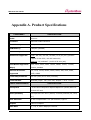
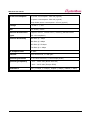
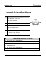
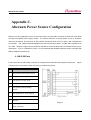
1
WiComm User Guide Revision History Revision Date 10/25/2005 Document Version 1.0 Pages Description All Initial release by jhkim Jhkim 11/29/2005 1.0a Added console commands Added front page Copyright 2005 SystemBase Co., Ltd. All rights reserved. Internet Homepage http://www.sysbas.com/ Tel 82-2-855-0501 FAX 82-2-855-0580 th 16 Fl. Daerung Post Tower-1, 212-8, Guro-dong, Guro-gu, Seoul, Korea For any inquiries or comments, contact to [email protected] 2 WiComm User Guide 3 WiComm User Guide Contents Chapter 1. Product Overview 7 1. Introduction 7 2. Package Contents 7 3. About This User Guide 8 4. Windows™ System Requirements 8 5. Wireless Device Server Requirements 8 6. Component Descriptions 10 7. LED Indicators 11 8. Reset Button Functions 12 9. Factory Default Settings 13 1) Port Parameters and Modbus Settings 13 2) Configuration Notes 14 Chapter 2. Hardware Installation 15 1. Installing WiComm 15 Chapter 3. Configuration & Management 17 1. Configuration Options 17 1) ExtendView Utility 17 2) Installing the ExtendView Utility (Windows operating systems) 17 3) Web Browser Interface 18 4) HP Web JetAdmin Utility 18 5) Command Console 18 2. Using the ExtendView Utility to Configure WiComm 18 3. Using the Web Browser Interface to Configure WiComm 20 4. Using the Telnet Command Line to Configure WiComm 22 5. Using the Serial Console to Configure WiComm 23 6. First-Time Configuration of WiComm Using 802.11b Network 24 7. Verifying WiComm’s Connection to a Serial Device 25 4 WiComm User Guide 8. Changing the Serial Settings 26 1) Using the ExtendView Utility to Change the Serial Settings 26 2) About Baud Rate 26 3) Serial Port Protocol 27 9. Using the Modbus Protocol 28 1) Serial Transmission Modes 28 2) Typical Modbus Applications 28 3) Changing the Modbus Settings 29 Chapter 4. Console Commands 30 1. Network Commands 30 2. Port Commands 37 3. Server Information Commands 38 4. Service Commands 41 5. String Commands 43 6. TCP/IP Commands 44 7. Power Configuration Commands 48 8. Firmware Update 49 9. Other Commands 50 Chapter 5. Troubleshooting 53 1. Introduction 53 2. Troubleshooting Installation Problems 53 3. Troubleshooting Network Configuration Problems 54 4. Troubleshooting Windows Problems 55 5. Troubleshooting Wireless Configuration Problems 55 Appendix A. Product Specifications 56 Appendix B. Serial Port Pinouts 58 Appendix C. Alternate Power Source Configuration 60 1. RS-232 Port 60 5 WiComm User Guide 2. RS-422 / 485 Full Duplex Port 61 3. RS-485 Half-Duplex Port 62 Appendix D. Antenna Specifications 63 1. Antenna Assembly 63 2. Antenna Cable Assembly 64 6 WiComm User Guide Chapter 1. Product Overview 1. Introduction WiComm is a high-performance, standalone device designed to connect a wide range of equipment (i.e., security devices, telecommunications equipment, modems, data display devices, industrial instrumentation, etc.) to wireless LAN. WiComm supports RS232, RS422, or RS485 serial interfaces at a variety of baud rates (data transmission speeds), automatically senses both 100baseTX Fast Ethernet and 10baseT Ethernet network connections, and the connects to 802.11b wireless networks as well. Other than the standard model, WiComm also includes a model that supports Modbus protocol, which is used to communicate with many types of industrial devices (e.g., instruments, meters, controllers, switches, etc.) over a serial-to-Wireless LAN connection. The installation can be performed by the least-experienced users, while providing networking professionals with advanced features for configuration. We are confident that you will enjoy the many features of WiComm. 2. Package Contents 1 piece of WiComm Software & Documentation CD Power Supply Adapter Serial Cable 7 WiComm User Guide 3. About This User Guide This User’s Guide contains information on system requirements, basic troubleshooting, and instructions on the following: Installing WiComm hardware Configuring WiComm for use with a serial device Configuring WiComm for use on your network Configuring WiComm using the ExtendView Utility NOTE: WiComm can be used with a variety of network operating systems and protocols. Please refer to Chapter 3. Configuration & Management for detailed information. 4. Windows™ System Requirements To configure the settings of WiComm using the provided ExtendView Utility in Windows, your Windowsbased system should include the following components: A PC with a 133 MHz or higher processor Microsoft Windows 98SE, ME, 2000, XP, or 2003 server operating system At least 64 MB of RAM (memory) At least 10 MB of free hard disk space (to install the software) A CD-ROM drive (to load the software) An Internet connection through a cable or DSL modem, or any other means 5. Wireless Device Server Requirements To use the wireless Device Server, you need an 802.11b wireless network consisting of either of the 8 WiComm User Guide following: An 802.11b wireless-enabled PC or device to be directly connected to WiComm (Ad-Hoc or Peer-to-Peer Mode) An 802.11b wireless access point that allows wireless and wired Ethernet-enabled computers to connect to WiComm To configure the wireless Device Server, you will need the following information from your wireless network administrator: Wireless Mode used (Infrastructure or Ad-Hoc) The SSID (service set identifier) for your wireless network. The Radio Frequency Channel of the wireless network If you are using TCP/IP (recommended for Windows Networks) and not connected to a DHCP (Dynamic Host Configuration Protocol) server (for obtaining an IP Address automatically), you will need a unique IP Address for the wireless Device Server (for example: 192.168.1.14). If WiComm is not on the same IP subnet as the computers you are connecting from, you will also need a subnet mask and a router (default gateway) address. Wireless Security Settings (WEP keys, 802.1x settings, etc.) 9 WiComm User Guide 6. Component Descriptions WiComm includes the following components as described below: Power connector – The power supply cable plugs into this connector. Reset button – Pressing this button for less than five seconds will print a test page (if the device is connected to a serial printer). Pressing and holding this button for more than five seconds will reset WiComm to factory default settings. LED status indicators – Used to indicate the operational states of WiComm. Refer to the next page for detailed LED status light descriptions. LAN port – This port (8-pin RJ45 jack) is used for connecting WiComm to an Ethernet card, hub, router, or other wired access point for network access. Serial port – This port (PC-compatible 9-pin male DB-9 connector) can be configured to connect WiComm to equipment that uses the RS232, RS422, or RS485 serial interface. 10 WiComm User Guide 7. LED Indicators WiComm provides three multifunction LED (Light Emitting Diode) indicators (yellow, green, and orange) for easy monitoring. The following table defines the function of each LED. LED POWER State ON The device is receiving power OFF The device is not receiving power (ORANGE) Blinking Yellow OFF Green OFF Yellow ON Green OFF Yellow Blinking Green OFF LINK (YELLOW / GREEN) Status Yellow OFF Green ON Yellow OFF Green Blinking Yellow ON Green ON Yellow Blinking Green Blinking The device’s power supply is malfunctioning No network activity 10baseT network active 10baseT network data received 100baseTX network active 100baseTX network data received Wireless network active Wireless network data received 11 WiComm User Guide 8. Reset Button Functions Action Result Depress for less than 5 Generates configuration data that can be viewed using a seconds terminal emulator (e.g., Windows Hyper Terminal) or other equipment that can display ASCII characters, or it will initiate a test page if WiComm is connected to a serial printer. Depress for more than 5 Resets WiComm’s configuration to factory defaults (cold seconds reset). The unit will automatically re-initialize after updating the configuration memory. Depress for 3 seconds Places the device into console configuration mode, during power up which can be used to configure the device via WiComm’s serial port. 12 WiComm User Guide 9. Factory Default Settings WiComm is shipped with a default configuration that will work with the most common serial-to-Ethernet and wireless connections. The default settings can be changed to suit specific installation requirements via the ExtendView Utility, the embedded Web server, or via a Telnet connection to WiComm’s internal console. The factory default settings can be easily restored at any time by performing a cold reset (press and hold the pushbutton on the device for more than five seconds). 1) Port Parameters and Modbus Settings Parameter Description Settings CHARACTER bits per character 7, 8 (default) FLOW flow control NONE (default), Xon/Xoff, CTS/RTS PARITY parity NONE (default), EVEN, ODD, MARK, or SPACE SPEED baud rate (bits per second) 300, 600, 1200, 2400, 3600, 4800, 7200, 9600 (default), 14400, 19200, 38400, 57600, 76800, 115200 (console port default), 230400, 460800 STOP stop bits per character 1 (default), 2 MODE line mode (serial port protocol) 232 (default), 422, 485, 485HD, Disabled ECABLE E-Cable mode (for TCP Enable, Disable (default) connections) ECADDR E-Cable destination IP address (set by user) ECONN E-Cable connection attempt 20 seconds time ECPORT E-Cable destination IP port 9100 (default), or set by user number 13 WiComm User Guide MULTI multidrop protocol Host (default), Modbus MBTYPE Modbus attached device type RTU slave (default)2, ASCII slave MBINIT Modbus initialization delay 100 – 3276 ms (default = 100 ms) interval MBAUTOID Modbus auto slave ID Enable (default)1, Disable MBCHARTMO Modbus character timeout 10 – 3000 ms (default = 100 ms) interval MBMSGTMO Modbus message timeout 10 – 3000 ms (default = 1000 ms) interval (N/A) Modbus/TCP Exception handling Enable, Disable (default) 2) Configuration Notes 1. The Modbus/TCP protocol contains a “Unit ID” field to identify multiple Modbus slave devices that are accessible at a single IP address. When the Modbus/TCP command contains a Unit ID, the Modbus Gateway can pass the Unit ID to Modbus serial devices, which allows multiple serial devices to be linked with a Modbus Gateway. When Auto Slave ID is enabled, a unit ID will be assigned automatically. If the Auto Slave ID is disabled, a unit ID (any number between 1 and 247) must be manually assigned in the Slave ID field. 2. When the Modbus serial protocol is set to Modbus/RTU, WiComm is ready to receive connection requests from Modbus/TCP master devices. Each message packet is determined by a character timeout. An incorrect character timeout may cause a CRC (Cyclic Redundancy Check) checksum error. Modbus ASCII slave mode functions the same as Modbus/RTU slave mode, except that the data format is Modbus/ASCII. 3. The Modbus/TCP Exception is in effect when the Modbus Gateway connects a Modbus/TCP Master with Modbus serial slave devices. When the Modbus Gateway cannot get a response from Modbus serial devices, the Modbus serial protocol will not respond to the master device. However, the TCP protocol has a longer waiting time, which could cause a network traffic problem for Modbus/TCP. For this reason, the Modbus Gateway can automatically send a Modbus exception code 16 to the Modbus/TCP master device when there is not response from the Modbus serial slave devices, thereby making overall network communication much more efficient. 14 WiComm User Guide Chapter 2. Hardware Installation 1. Installing WiComm Follow the steps below to install WiComm. In most cases, WiComm’s factory default settings should be sufficient for most serial connections; however, some of the configuration settings may have to be changed for your particular installation. WiComm can be wall mounted, set on the desktop, or mounted using the optional DIN rail kit. 1. Before attempting to install WiComm, make sure you have installed and set up your serial equipment as described in the documentation that came with the device. 2. Write down the 12-digit MAC (Media Access Code) address printed on the label located on the bottom of WiComm (for example: 004017023F96). You may need this number in order to configure WiComm. 3. Connect WiComm to your equipment using a standard PC-compatible 9-pin (DB-9) serial cable for RS-232 type devices (refer to Appendix A for pinout descriptions). A custom cable may be required for RS-422 and RS-485-type serial devices. For RS-422/RS-485-type devices, a 120-ohm terminating resistor may be required at the receiving end of a differential pair if the device is at the end of the cable (refer to Appendix C for detailed information). 4. Plug WiComm power supply adapter into a suitable AC receptacle, and then plug the power supply cable into WiComm. WiComm will run through a sequence of power-up diagnostics for a few seconds. If WiComm is operating properly, the LEDs will blink momentarily and then go out, the yellow and green LEDs will illuminate if the wireless network is active, and the orange LED will illuminate, indicating the device is receiving power. If the orange LED blinks continuously in a regular pattern, a problem exists. If this is the case, try powering the unit OFF and then ON again. If the problem persists, refer to the Troubleshooting section in this User Guide. 5. Choose a spot for WiComm within the communication range of the nearest Access Point. Connect WiComm to your network through a switch or hub using a category 5 (CAT5) Ethernet cable when wired 15 WiComm User Guide communication is required. WiComm’s IP address must be configured before a network connection is available. If your network offers DHCP (Dynamic Host Configuration Protocol), WiComm will automatically search for a DHCP server upon power up and obtain an IP address. If your network does not offer DHCP, a static (fixed) IP address must be assigned (see your system administrator for assistance). In most cases, a fixed IP address is preferred because a DHCP server may not always assign the same IP address to WiComm when WiComm is powered ON. WiComm also supports the following protocols. See your system administrator for help. arp rarp BootP NOTE: The IP address must be within a valid range, unique to your network, and in the same subnet as your PC (refer to Appendix A for a list of TCP port connections). NOTE: If a wired connection is established to WiComm, the wireless link will be disabled. 16 WiComm User Guide Chapter 3. Configuration & Management 1. Configuration Options After the hardware installation has been successfully completed, WiComm can be configured and managed via an Ethernet and/or wireless connection using the ExtendView Utility (recommended), the embedded web (HTTP) server pages, or WiComm’s internal configuration console, which can be accessed via a Telnet connection or directly through WiComm’s serial port. Additional options for configuration and management of WiComm are available as third-party utilities that can be downloaded from their respective web sites as noted below. You can configure it via an Ethernet connection or configure it via a wireless connection as described. 1) ExtendView Utility a Windows TCP/IP utility used for configuring WiComm’s port, network, and wireless settings. uses a 32-bit graphical user interface. works with Windows PCs running the TCP/IP protocol. included on WiComm Software & Documentation CD. after installation, this utility can be run from the START menu. 2) Installing the ExtendView Utility (Windows operating systems) 1. Ensure your PC is connected and has access to your network. 2. Connect WiComm to either wireless or wired network. Ensure WiComm is powered ON. 3. Insert the CD supplied with your WiComm into the CD-ROM drive of your computer. The CD should automatically start and display a menu screen. 4. Select Install ExtendView. After the installation is complete, you can start the ExtendView utility by clicking on Start, Programs, and then ExtendView. 17 WiComm User Guide 3) Web Browser Interface allows you to configure WiComm with a standard web browser (e.g., Firefox or Microsoft Internet Explorer). no additional software is needed on the system. can be used on any system that supports web browser capabilities. type the IP address into your web browser address bar to connect. the default password is ACCESS (not case sensitive). 4) HP Web JetAdmin Utility a web browser-based utility (works with browsers like Internet Explorer or Firefox). can be downloaded from the HP web site http://www.hp.com. 5) Command Console a command-line-oriented console. contains some advanced features not available through ExtendView or the Web Browser Interface. the default password is ACCESS. can be accessed via Telnet or via a direct connection to WiComm’s serial port. When connecting via Telnet, enter the IP address of WiComm and the TCP port. (by default, the port is 9100 or 3001) When connecting via serial port, reset button should be pressed for 3 seconds upon poweron. Press Enter after the power is on to enter the command mode. type HELP for a list of console commands. 2. Using the ExtendView Utility to Configure WiComm For Microsoft Windows operating systems, the ExtendView Utility is the recommended method of configuring one or more Device Servers on your network. Once WiComm obtains an IP address (occurs automatically when the unit is powered ON and connected to a DHCP network), the ExtendView Utility’s auto-discovery 18 WiComm User Guide feature will search for and locate all Device Severs on the network and then display the IP address for each discovered Device Server. 1. Start the ExtendView Utility by clicking on Start, Programs, and then ExtendView. 2. When the Welcome screen appears, click on Next, choose any name for your View Name, select Automatically create a view with default settings (or configure the view to your preferences), and then click on Finish. 3. Right-click on WiComm that you want to configure from the displayed list, and then left-click on Configuration. The default Device Server name is TWC_xxxxxx (where xxxxxx is the last six digits of the MAC address from the label located on the back of WiComm). 4. If you are using TCP/IP (recommended for Windows) and you do not have a DHCP server (see note below), you will need to manually assign a valid IP Address (if you are not sure what IP address is valid, ask your network administrator), and then click on OK. NOTE: If you are using DHCP on your network, WiComm should have acquired valid IP settings at this point and no further configuration is necessary. installations, a static IP address is preferred. However, for most If your DHCP server does not allow WiComm to keep its assigned IP address permanently, then you must manually assign an IP address. In this case, use a static IP address outside the range reserved for DHCP (see your DHCP server documentation for details). To assign a static IP address, right-click on WiComm in the menu, and then select Configuration. On the TCP/IP tab, under IP Address Resolution, select Set Permanent, and assign a valid static IP address for your network. Click on OK to save the new settings. 5. Configure the 802.11b wireless settings. To operate on an 802.11b network, WiComm configuration must be set to the same configuration as your wireless network to allow WiComm to communicate over your wireless network. All nodes of a wireless network need to have the same settings to allow communication between the devices. Following parameters need to be set. wireless mode (ad-hoc or infrastructure) SSID channel data rate wireless security settings (WEP keys, 802.1x settings, etc.) 19 WiComm User Guide NOTE: The ExtendView Utility and Web Browser interface contain help screens to assist you with WiComm’s security settings. 3. Using the Web Browser Interface to Configure WiComm To configure WiComm using non-Windows operating systems (e.g., Unix systems), a standard web browser (e.g., Internet Explorer or Firefox) can be used to access WiComm’s embedded Web (HTTP) server pages, which contain WiComm’s configuration options. No additional software is required. 1. Make sure that WiComm and the PC are connected on the same network. 2. Ensure that the power of WiComm is on. For the wired configuration, connect LAN cable to the LAN port of WiComm, and for the wireless configuration, make sure the wireless parameters are correctly set. More information on wireless setting is discussed in details on 6. First-time Configuration of WiComm Using 802.11b Network. Now, if the network settings are correct, you can connect to WiComm by its IP address. If you know the IP address of WiComm, you can skip to the step 5. For the case where IP address is not known to the user, (i.e. when using the DHCP server) you can detect the IP address of WiComm via steps 3 and 4. 3. In order to view the IP settings of WiComm, it needs to be connected to either the PC or any serial device that can print ASCII characters, via serial connection. 4. When the powers of both WiComm and the PC (or the serial device) are on, press the reset button of WiComm for about 1 second or more, but not longer than 5 seconds. Then the WiComm configuration data is transferred via serial port. Factory default IP address of WiComm is 192.0.0.192. Be careful not to assign the same IP address with the PC, since this might cause IP address collision. 5. From the host computer, open a standard web browser, enter the IP address of WiComm into the address bar of the web browser, and then press Enter. The Web Browser Utility screen will be displayed. Click on the Login menu selection, enter the password (default is ACCESS), and then click on Submit. The main screen will be displayed, allowing you to configure the settings of WiComm. The menu selections are displayed on the left side of the screen, and the individual settings are located at the top of the screen. 6. Configure the 802.11b wireless settings. To operate on an 802.11b network, WiComm configuration must be set to the same configuration as your wireless network to allow WiComm to communicate over your wireless network. All nodes of a wireless network need to have the same settings to allow communication between the devices. Following parameters need to be set. 20 WiComm User Guide wireless mode (ad-hoc or infrastructure) SSID channel data rate wireless security settings (WEP keys, 802.1x settings, etc.) 21 WiComm User Guide 4. Using the Telnet Command Line to Configure WiComm 1. Ensure WiComm is connected via an Ethernet cable to the host computer. 2. From the Windows Start menu, click on Run, and then type the following command (where x.x.x.x. is the IP address of WiComm). The system will use the default port 23 to access WiComm via Telnet. telnet X.X.X.X 3. After a connection is established, press Enter to get the "#" prompt, enter the password ACCESS (it will not ‘echo’ on your screen), and type anything in response to the Enter Username> prompt. When the Local> prompt appears, you are ready to enter commands. 22 WiComm User Guide 5. Using the Serial Console to Configure WiComm WiComm’s command console can be accessed via a direct connection to WiComm’s serial port using a COM port emulator and a null modem serial cable. 1. Attach one end of a null modem serial cable to the DB-9 serial port of WiComm, and the other end of the cable to the COM port on your computer. 2. Press and hold WiComm’s test button for at least three seconds while powering up the device. When WiComm has finished initializing, the internal configuration console will be ready to accept commands. 3. Start a terminal emulation program (e.g., Windows HyperTerminal), making sure you are connecting with the relevant COM port. 4. Use the following settings for the connection: BITS PER SECOND: 115200 bps DATA BITS: 8 PARITY: NONE STOP BITS: 1 FLOW CONTROL: NONE 5. Once connected, press Enter to continue. The Local> prompt will appear, indicating that the system is ready to accept commands. For a list of commands, type help at the command prompt. 23 WiComm User Guide 6. First-Time Configuration of WiComm Using 802.11b Network Although WiComm can be configured using a wireless connection, it is recommended that WiComm be initially configured using a wired connection as described on the previous pages. WiComm’s wireless network interface supports all modes of 802.11b at 1, 2, 5.5, and 11 Mbps. The wireless network is only active if WiComm is not connected to a wired network. If a wired link is established to WiComm, the wireless link is automatically disabled. To configure the wireless Device Server for the first time from a computer via an 802.11b wireless connection, you will need to temporarily change your computer’s settings to match the default settings of WiComm as follows: Wireless Mode: Ad-Hoc (sometimes referred to as Peer-to-Peer) Channel: 11 SSID (or wireless network name): serserv You should now be able to configure your WiComm using either the ExtendView Utility or the Web Browser Interface as described in the previous sections. NOTE: Be sure to set your PC back to its original wireless settings after you finish configuring the wireless Device Server. NOTE: It is not necessary to change your computer’s settings if you are configuring WiComm’s settings via an Ethernet connection. 24 WiComm User Guide 7. Verifying WiComm’s Connection to a Serial Device 1. Verify that both WiComm and the connected equipment are powered on and ready, and that a serial cable is properly connected between WiComm and equipment (i.e., transmit signal output from WiComm going to the receive signal input on the equipment, ground leads connected together, etc.). NOTE: Before attempting to use WiComm, you must verify the connection between WiComm and the connected equipment. If this connection is not working, you will not be able to send and/or receive data from the connected equipment. 2. Verify that WiComm’s port settings (i.e., baud rate, flow control, character bit size, parity, etc.) exactly match the settings of the connected device’s port. 3. If the equipment connected to WiComm is able to display or print ASCII characters (such as a terminal emulator or serial printer), then communication between the devices can be verified by pressing the Reset button on WiComm for about one second (but less than five seconds), which will initiate the output of configuration data from WiComm to the connected equipment. If communication has been successfully established between the two devices, the equipment should be able to display or print WiComm’s configuration data. If no data is displayed or printed, verify that both devices are powered ON, are properly connected using a suitable serial cable, and are using compatible serial port parameters. The two most common serial communication problems are due to the either the cabling and/or mismatched serial port parameters. NOTE: If WiComm is connected to equipment that cannot display or print ASCII characters, then it is recommended that another device capable of displaying or printing ASCII characters be temporarily connected to WiComm in order to verify the serial connection. After successful communication is verified using the temporary device, reconnect the original device, making sure that the original device is configured with serial port parameters that match the tested connection. If you are unable to establish a working serial connection between WiComm and the connected equipment, refer to the troubleshooting chapter in this User Guide. For additional troubleshooting assistance, contact SystemBase staff. 25 WiComm User Guide 8. Changing the Serial Settings In order to establish communication between WiComm and a device, the serial settings for both devices must match. The serial settings can be changed using ExtendView (recommended), the web browser interface, or WiComm’s internal configuration console (refer to the previous sections for the installation and use of these utilities). 1) Using the ExtendView Utility to Change the Serial Settings 1. Start the ExtendView Utility by clicking on Start, Programs, then ExtendView. 2. From the main menu, click on Options, and then click on Configuration. 3. Click on the Output Port tab, and then click on the Serial Settings button. 4. After configuring the serial settings, click on OK to continue. 2) About Baud Rate In some cases it may be necessary to change the baud rate of the Device Sever in order to match the baud rate of a particular device where the baud rate is fixed. Baud is a measurement of transmission speed in asynchronous communication and represents the number of bits that are actually being sent over the media, not the amount of data that is actually moved from one device to the other. WiComm supports baud rates from 300 to 460800 bps. To ensure communication between connected serial devices, all other serial port parameters (mode, character bits, parity, etc.) must be identical for each serial device. 26 WiComm User Guide 3) Serial Port Protocol WiComm’s serial port protocol (data transmission mode) can be changed to match the particular characteristics of the connected device’s UART (Universal Asynchronous Receiver/Transmitter). WiComm supports the following serial port protocols, namely RS-232/422/485 on one hardware. Protocol RS-232 Description an interface between data terminal equipment and data communications equipment employing serial binary data interchange over a wired connection with a maximum range of 40 feet (12meters). RS-422 a data transmission system using balanced differential signals (voltages) to send serial binary data over a wired connection with a maximum range of 4,000 feet (1.2 km). RS-485 / RS-485HD a data transmission system using balanced differential signals (voltages) to send serial binary data over a wired connection with a maximum range of 4,000 feet (1.2 km). As many as 32 driver/receiver pairs can share a multi-drop network (4-wire at full duplex or 2-wire at half duplex). Many characteristics of the drivers and receivers are the same as RS-422. 27 WiComm User Guide 9. Using the Modbus Protocol Modbus is a widely used industrial device communications protocol that provides “client/server” communications between devices connected on different types of buses or networks. WiComm supports the Modbus serial line version of the protocol used for communicating with many types of industrial devices (e.g., instruments, meters, controllers, switches, etc.) over a serial-to-Ethernet connection. In general, WiComm operates as a transparent device between the host (master device) and the connected serial devices (slaves), sending and receiving data to and from one or more slave units (up to a maximum of 32 slave serial devices). WiComm uses the RS-232 and RS-485 serial port protocol (using a 9-pin connector) for Modbus communication. 1) Serial Transmission Modes Two connection protocol options are available between WiComm and the serial device: RTU (Remote Terminal Unit) Mode – allows for greater character density, which allows for better data throughput than ASCII mode. However, each message must be transmitted in a continuous stream of characters. ASCII (American Standard Code for Information Interchange) Mode – is used when the physical communication link or the capabilities of the serial device do not allow conformance with RTU mode requirements. 2) Typical Modbus Applications Many traditional Modbus devices can talk over an RS-485-type serial port provided that the transmission distance between the serial device and WiComm does not exceed 4,000 feet (1.2 km). When using the RS232-type serial port, the connection between WiComm and the serial device cannot exceed 40 feet (12 meters), which is sufficient for short point-to-point communications. Using WiComm configured as a Modbus master device, up to 32 Modbus slave devices can be placed on the same Modbus network using the RS-485-type serial port. In a master/slave configuration, the master serial device will always initiate communication with the slave devices, and the slave devices will never talk to each other. In unicast mode, WiComm can only address an 28 WiComm User Guide individual slave at one time with each slave having a unique network address. In this mode, when addressed by the master, each slave returns a reply to the master device. In broadcast mode, WiComm can address all the slave units simultaneously; however, in this case, the slave devices do not send a reply to the master device. 3) Changing the Modbus Settings In order to establish communication between WiComm and a serial device using the Modbus protocol, the Modbus settings for both devices must be compatible. WiComm’s Modbus settings can be changed using the ExtendView Utility (recommended), the web browser interface, or WiComm’s internal configuration console (refer to page 3-1 for detailed application use). 29 WiComm User Guide Chapter 4. Console Commands This chapter describes the console commands available from the internal command console through the serial port or Ethernet port via a Telnet session. 1. Network Commands The following group of commands configures network parameters. SH NW Displays summary network information sample output: WiFi Mode = INFRASTRUCTURE WiFi SSID: wicomm Speed = 11 Regulatory Domain = 704 WiFi FW Ver = 1F 1.7.1 AP density = LOW TTLS is Disabled WEP is Disabled Link DOWN SET NW AUTHtype Set WLAN Authentication type SET NW AUTHtype [OPEN |SHARED | TTLS | LEAP | WPA-PSK] (default = Open System) SH NW AUTH Shows the wireless authentication type sample output: 30 WiComm User Guide Authentication type= OPEN SYSTEM SET NW CHannel Set WLAN ad-hoc channel number SET NW CHannel n n = 1-11 (default = 11; value is ignored in Infrastructure mode) SET NW ENC Set WLAN Encryption Mode. Supported modes are none, 64 bit WEP, 128 bit WEP, and TKIP (WPA). SET NW ENC [DIsable | 64 | 128 | TKIP ] (default = Disable) SH NW ENC Shows the wireless encryption mode sample output: WiFi encryption is Disabled NOTE: The deprecated command SH NW WEP will also display this information. SET NW KEY# Selects WLAN WEP key entry SET NW KEY# n n = 1-4 (default = 1) SET NW KEYVAL Set the currently selected WLAN WEP key entry to the hex value given. SET NW KEYVAL <key> key=10 or 26 hex characters (default=<null>) SET NW MOde Set WLAN mode. SET NW MOde <mode> [Infrastructure | Ad-Hoc] (default = Infra) SH NW MODE Shows the wireless operating mode sample output: Wifi mode = AD-HOC (802.11) 31 WiComm User Guide SH NW RADio Shows the selected radio mode of operation sample output: Radio mode is 802.11b SET NW SPeed Set maximum WLAN speed. SET NW SPeed n n = 1,2,5.5 or 11 (default = 11) SH NW SPEED Show the maximum wireless data speed in megabits per second sample output: Speed = 11 SET NW SSid Set WLAN SSID SET NW SSid <name> User defined (default = printer) CL NW SSid Clears the SSID value so the server will connect to any AP. CL NW SSid SET NW BSsid Set WLAN BSSID (connect to a specific access point’s mac address) SET NW BSsid <value> User defined (MAC Address) CL NW BSsid Clears the BSSID value so the server uses just SSID and not a specific AP. CL NW BSsid SET NW RTS Set WLAN RTS threshold SET NW RTS n 32 WiComm User Guide n = 1-3000 (default = 2432) SH NW RTS Shows the configured wireless RTS threshold sample output: Wifi RTS Threshold = 2432 SET NW APDEN Set WLAN Access Point Density SET NW APDEN [LOW | MED | HI] (default = LOW) SH NW APDEN Shows the access point density sample output: AP Density = Low SH NW STATS Show the network I/O statistics sample output: WiFi statistics: TX Unicast frames: 0 TX Multicast frames: 0 TX Fragments: 0 TX Unicast octets: 0 TX Multicast octets: 0 TX Deferred: 0 TX Single retry frames: 0 TX Multiple retry frames: 0 TX Retry limit exceeded: 0 TX Discards: 0 RX Unicast frames: 0 RX Multicast frames: 0 RX Fragments: 0 RX Unicast octets: 0 RX Multicast octets: 0 RX FCS errors: 0 33 WiComm User Guide RX Discards no buffer: 0 TX Discards wrong SA: 0 RX Discards WEP undecr: 0 RX Msg in msg fragments: 0 RX Msg in Bad msg fragments: 0 SET NW CERTCN Set EAP Common Name SET NW CERTCN <name> User defined (default=<null>) SH NW CERTCN Shows the value of the first common name check string sample output: Common name 1 NOTE: The default for this string is a null (blank) string. NOTE: The deprecated command SH NW TTCN will also return this information. SET NW CERTCN2 Set second EAP Common Name SET NW CERTCN2 <name> User defined (default=<null>) SH NW CERTCN2 Shows the value of the second common name check string sample output: Common name 2 NOTE: The default for this string is a null (blank) string SET NW CERTEXP Set EAP Certificate Exponent value SET NW CERTEXP <exponent> User defined (default = 10001 Hex) SH NW CERTEXP Shows the value of the certificate exponent 34 WiComm User Guide sample output: 65537 (10001h) NOTE: The deprecated command SH NW TTEXP will also return this information. SET NW CERTKEY Set EAP Root Key SET NW CERTKEY <key value> User defined SET NW ID Set Authentication User ID This may include the realm, separated by a ‘@’ character. SET NW ID <user id> (default = anonymous) SH NW ID Shows the value of the authentication ID (including realm, if present) sample output: anonymous@somewhere NOTE: The default realm is a null (blank) string. NOTE: The deprecated command SH NW TTID will also return this information. SET NW PW Set the password used for the 802.1x EAP authentication, if enabled. SET NW PW <password> (default = anonymous) SET NW INAP Set EAP Inner-Authentication protocol SET NW INAP [PAP|MSCHAP_V2] (default = PAP) SH NW INAP Shows the selected inner authentication mode sample output: Authentication protocol = PAP NOTE: The deprecated command SH NW TTAP will also return this information. 35 WiComm User Guide SET NW REALM Set the realm portion of the 802.1x EAP authentication ID. This may also be set with the ID command. SET NW REALM <realm> (default = <null>) SH NW REALM Shows the realm associated with the authentication ID, if any. sample output: somewhere NOTE: The default realm is a null (blank) string. NOTE: The deprecated command SH NW TTRE will also return this information. SET NW WPAAUTO Enable or disable WPA auto mode. If enabled, WiComm will connect to a non-WPA access point if a WPA enabled access point is not available. Only valid when WPA is enabled (authentication type = TKIP). SET NW WPAAUTO [ENable | DIsable] (default = disabled) SH NW WPAAUTO Shows the state of the WPA auto connect flag sample output: WPA-AUTO Enabled SET NW WPAGROUP Enable or disable WPA group key mode. If enabled, this allows group keys to be used for data link encryption. SET NW WPAGROUP [ENABLE | DISABLE] (default = disabled) SH NW WPAGROUP Shows the state of the allow WPA group keys flag sample output: WPA-GROUP Disabled SET NW WPAPSK Set the WPA PSK pass phrase or hex key. This value is only used if the authentication mode is WPAPSK. 36 WiComm User Guide The argument to this command is either a pass phrase of 8-63 characters, or exactly 64 hex characters representing the 256 bit PSK value. SET NW WPAPSK <key> (default = “WiComm”) SET NW WPATRACE Set the WPA trace level. NOTE: This command is for diagnostic purposes only, and should not normally be used as the trace can affect performance. A value of 0 disables the trace. SET NW WPATRACE nn (default = 0) 2. Port Commands SH PORT Shows Port parameters sample output: Port Q-Size Type Attributes *S1 0 serial 115200 N 8 1 XON/XOFF RS232 SET PORT Set Parameters for specified port. The available commands are dependent on the port type. CLEAR PORT S1 JOB This command aborts the currently active job on the port specified. If the remote host is still connected, any further data received will be discarded. CL PORT S1 JOB SET PORT S1 FLOW Set serial port flow control to NONE, XON/XOFF, CTS, or DSR SET PORT S1 FLOW <flow> (default = None) SET PORT S1 PARITY Set serial port parity to NONE, EVEN, ODD, MARK, or SPACE SET PORT S1 Parity <parity> 37 WiComm User Guide (Default = None) SET PORT S1 SIZE Set the data bits on the serial port SET PORT S1 Signal [7 | 8] (default = 8) SET PORT S1 SPeed Set serial port baud rate. Options for BAUD are 300, 600, 1200, 2400, 7200, 9600, 19200, 38400, 57600, 115200, 230400, and 460800 SET PORT S1 SPEED <baudrate> (default = 115200) SET PORT S1 STOP Set serial port stop bits per character. SET PORT S1 STOP [1 | 2] (default = 1) 3. Server Information Commands SET SERVEr DEscription Set the server description string SET SERVEr DEscription <description-string> SET SERVEr NAme Set server node name SET SERVEr NAme <name> (default = “TWC_xxxxxx”, where xxxxxx are the last 6 hex digits of the MAC address) SET SNMP GETCOMM Set Community Name SET SNMP GETCOMM <string> (default = “public”) 38 WiComm User Guide SET SNMP JETADmin Enable or disable JetAdmin compatibility SET SNMP JETADmin [ ENable | DIsable] (default = enabled) SET SNMP SETCOMM1 Set Community 1 Name SET SNMP SETCOMM1 <string> (default = “internal?”) SET SNMP SETCOMM2 Set Community 2 Name SET SNMP SETCOMM2 <string> (default = “pass”) SET SNMP CONtact Set system contact string SET SNMP CONtact <string> (default = <null>) SET SNMP LOCation Set the system location string SET SNMP LOCation <string> (default = <null>) SH SERIAL Displays the serial number of the unit sample output: Serial number is 9047595 SH SERVEr Shows Server parameters sample output: Serial Server Serial # 9047595 Address: 00-40-17-8A-0E-2B Name: TWC_8A0E2B Number: 0 Identification: Network Server Enabled Characteristics: 39 WiComm User Guide Link DOWN SH SERVEr CO Shows Server network statistics sample output: Seconds Since Zeroed: 163 Frames Sent, 1 Collision: 26 Bytes Received: 72950 Frames Sent, 2+ Collision: 5 Bytes Sent: 18726 Send Failures: 0 Frames Received: 752 Send Failure Reasons: 0 Frames Sent: 181 Receive Failures: 503 Multicast Bytes Rcv'd: 64474 Receive Failure Reasons: 1 Multicast Bytes Sent: 2406 Unrecognized Destination: 0 Multicast Frames Rcv'd: 626 Data Overrun: 0 Multicast Frames Sent: 11 User Buffer Unavailable: 0 Frames Sent, Deferred: 2014 System Buffer Unavailable: 1 SH SNMP Shows the state of the SNMP protocol enable sample output: SNMP is Enabled SH VErsion Shows the WiComm’s firmware version sample output: serial server Firmware Ver. 4.19 (2004.10.31) Boot Ver. 1.4 16Mbit Flash Protocols supported: NetBIOS SNMP TCP/IP EMail DHCP Zero Clears and resets the network statistic counters 40 WiComm User Guide 4. Service Commands SET SERVI <service name> BOT Set beginning of transmission (BOT) string index for service SET SERVI <service name> BOT nn (default = 1) SET SERVI <service name> EOT Set end of transmission (EOT) string index for service SET SERVI <service name> EOT nn (default = 1) SH SERVI STRings [string_num] Defines the BOT and EOT strings used in services. If string_num is provided then the specific string definition and expansion is displayed. If string_num is not provided, then all string definitions (but not their expansions) are displayed. sample output: 10: \FF\04\FF\05\FF\06\FF\08 SET SERVI <service name> FIlter Set filter index for service. SET SERVI <service name> FIlter nn SH SERVI FILters Shows filter settings. sample output: # Service Name Filter 1 TWC_FFFFFF 0: No Filter 2 BINARY_P1 0: No Filter 3 TEXT_P1 1: Text Substitution m= LF, r= CRLF 4 TWC_FFFFFF_P1_4 0: No Filter 5 TWC_FFFFFF_P1_5 0: No Filter 6 TWC_FFFFFF_P1_AT 4: PostScript Tagged Binary SET SERVI <service name> FMS Set filter 1 (text replacement filter) match string index. If the index is zero, the default string of <LF> (line 41 WiComm User Guide feed) is used. SET SERVI <service name> FRM nn (default = 0 ) SET SERVI <service name> FRS Set filter 1 (text replacement filter) replace string index. If the index is zero, the default string of <CRLF> (carriage return-line feed) is used. SET SERVI <service name> FRS nn (default = 0 ) SET SERVI <service name> IP Enable or disable all IP based jobs (lpd, raw tcp, ftp, etc.) on the service. SET SERVI <service name> IP [ENable | DIsable] (default = enabled for service 1 and 2, disabled for all others) SET SERVI <service name> NAme Change the service name SET SERVI <service name> NAme <newname> (default varies by service) SET SERVI <service name> POrt Set the output port associated with a service. SET SERVI <service name> POrt <portname> (default = “S1”) SET SERVI <service name> PRIority Set priority for service if multiple service try to transmit data at the same time. Higher priority services are serviced first. SET SERVI <service name> PRIority nn (default = 10) SH SERVI PRI [service_num] This shows the priority of a specific service. If service_num is not provided, the priority of all services is listed. SET SERVI <service name> RECeive Set receive only mode for a service. This option is rarely required, but some host applications do not 42 WiComm User Guide operate properly if data is received back from the serial device. SET SERVI <service name> RECeive [ENable | DIsable] (default = disabled) SET SERVI <service name> TCP Set raw TCP port for service. If port number is zero, raw TCP is disabled on that service. SET SERVI <service name> TCP nn (default = 9100 for service 1, 3001 for service 2) SH SERVI SUMmary [service_num] Shows the basic parameters for a specific service. If service_num is not provided, parameters for all services are displayed. NOTE: The command SH SERVI is equivalent to SHOW SERVI SUM. 5. String Commands These commands configure strings used with services and service filters. SET STRing Set service string table entry. (Note, String 1-11 cannot be set or changed). SET STRing <string #> ”value” CL STRing Clears the service string table entry. CL STRing <string #> SH STRing [string_num] Defines the BOT and EOT strings used in services. If string_num is provided then the specific string definition and expansion is displayed. If string_num is not provided, then all string definitions (but not their expansions) are displayed. sample output: 1: 2: \1BE 3: \04 4: \1B%-12345X 43 WiComm User Guide 5: @PJL 6: ENTER LANGUAGE= 7: PCL\0A 8: POSTSCRIPT\0A 9: \FF\04\FF\05\FF\06\FF\07 10: \FF\04\FF\05\FF\06\FF\08 11: \0C SH FILters Shows the available filters that can be used to modify a job stream. sample output: # Filter 0 No Filter 1 Text Substitution 2 AppleTalk 3 Text to PostScript 4 PostScript Tagged Binary 5 DC1 Special 6. TCP/IP Commands SET IP ACcess Allow or disallow access to a block of remote addresses SET IP ACcess [EN | DI | ALL] aa.bb.cc.dd {MAsk ee.ff.gg.hh] (default = empty list) SET IP RANge Allow or disallow access to a range of remote addresses SET IP RANge [EN | DI | ALL] aa.bb.cc.dd {MAx ee.ff.gg.hh] (default = empty list) SH IP ACcess Display current access list settings Sample output: 44 WiComm User Guide All hosts permitted access SET IP ADdress Set server IP address SET IP ADdress aa.bb.cc.dd (default = 192.0.0.192) SET IP ARP ENable Enable or disable setting of IP address with an ARP packet SET ARP [ENable | DIsable] (default = enable) SET IP BAnner Enable or disable printing of job banner on LPD jobs SET IP BAnner [ENable | DIsable] (default = disable) SET IP CHKSUM Enable or disable verification of the IP checksum on received packets SET IP CHKSUM [ENable | DIsable] (default = enable) SET IP BOot Number of tries for each enabled IP boot method, if not set to STATIC SET IP BOot n (default = 3) SET IP ENable Enable or disable all IP based protocols SET IP [ENable | DIsable] (default = enable) SET IP FTIme If enabled, the IP timeout is measured in seconds. If disabled, the IP timeout is in minutes. SET IP FTIme [ENable | DIsable] (default = disable) 45 WiComm User Guide SET IP FTP Enable or disable the FTP protocol SET IP FTP [ENable | DIsable] (default = enable) SET IP HTTP Enable or disable the HTTP protocol SET IP HTTP [ENable | DIsable] (default = enable) SET IP KEepalive Set interval at which TCP keepalive packets are sent on a connection, in minutes. SET IP KEepalive n (default = 5 min) SET IP LPD Enable or disable the LPD protocol SET IP LPD [ENable | DIsable] (default = enable) SET IP MEthod Set method of getting IP address SET IP MEthod [ AUTO | BOOTP | RARP | DHCP | STATIC ] (default = AUTO) SET IP PIng Send IP ping packets to test connection to remote host. SET IP PIng aa.bb.cc.dd SET IP PRObe Enable or disable TCP connection probes SET IP PRObe [ENable | DIsable] (default = disable) SET IP RARp Enable setting of default router and/or subnet mask based on the source of a RARP IP address set. SET IP RARp nn 46 WiComm User Guide nn: 0=both 1=no subnet, 2=no router, 3=neither (default = 0) SET IP REtry Enable or disable LPD retry on incomplete job SET IP REtry [ENable | DIsable] (default = disable) SET IP ROuter Set the default router address SET IP ROuter aa.bb.cc.dd (default = 0.0.0.0) SET IP SUbnet Set the IP subnet mask SET IP SUbnet aa.bb.cc.dd (default = 0.0.0.0) SET IP TCP Enable or disable the raw TCP (9100) protocol SET IP TCP [ENable | DIsable] (default = enable) SET IP TELnet Enable or disable the TELNET protocol SET IP TELnet [ENable | DIsable] (default = enable) SET IP TFTP Enable or disable the TFTP protocol SET IP TFTP [ENable | DIsable ] (default = enable) SET IP TImeout Set TCP Inactivity timeout , in seconds if fast timeout is enabled, otherwise in minutes. SET IP TImeout n (default = 1 minute) 47 WiComm User Guide SET IP WIndow Set TCP maximum window size in bytes SET IP WIndow nn (default = 10240) SH IP Shows TCP/IP related Parameters sample output: IP is enabled IP address 192.0.0.192 Boot tries 3 Subnet mask 0.0.0.0 Boot method AUTO IP Gateway 0.0.0.0 Max window 10240 (set manually) LPD banner disabled Timeout 1 min LPD retries are disabled Keepalive 5 min Service Port TCP port xxxxxx_S1_A S1 9100 xxxxxx_S1_B S1 3001 7. Power Configuration Commands SET POWER DELAY nnnn This is the time, in milliseconds, to wait before the processor goes into power save mode. If no I/O occurs on the network or from the attached peripheral within this time period, the processor will go into low power mode. The value must be between 0 and 1800000 (30 minutes). A value of 0 disables processor power saving. The default value is 0. SET POWER PERIOD nnnn If radio power save is enabled, this is the time, in milliseconds, between radio wake up events. The value must be between 1 and 65535. The default value is 65535. SET POWER WINDOW nnnn This is the time, in milliseconds, the radio stays awake each time it wakes up in power save mode (i.e., every PERIOD msec the radio wakes up for WINDOW msec to see if there is traffic for it). The value is in 48 WiComm User Guide the range of 0-100. Zero disables the radio power save mode (the CPU may still go into power save based on the DELAY parameter). The default is 0 (disabled). 8. Firmware Update These commands set up the unit for performing an update of the server firmware. SET LOAd ENable If enabled, the firmware performs a soft reset and enters the server boot program after the next EXIT command. This command should not be used with WiComm end-users. It remains in the firmware for diagnostic use. SET LOAd (ENable | DIsable ] (default = disable) SET LOAd HOst Set the node name of the Netware boot host. Note that Netware download is not supported on the Serial Server, so this command should not be used. SET LOAd HOst <name> (default = <null>) SET LOAd IP Set the IP address of the source computer for a TFTP get operation. SET LOAd IP aa.bb.cc.dd (default = 0.0.0.0) SET LOAd SOftware Set filename on host for TFTP get update. SET LOAd SOftware <filename> SET LOAd TFTP Initiate firmware update via a TFTP get operation. The TFTP server address must be set via SET LOAd IP and the filename via SET LOAd SOfware. The server will reset after the firmware update is completed. SET LOAd TFTP SET LOAd XModem 49 WiComm User Guide Initiate firmare update via the serial console using the XModem protocol. The server will reset after the firmware update is completed. SET LOAd XModem SH LOAd Shows the firmware update parameters sample output: Firmware load is disabled Load Host IP = 0.0.0.0 Software file = xxxx.bin Load Host Name = 9. Other Commands SET DEFAULT Set parameters to factory defaults EXIT This command exits the current configuration console session. EXIT SH FATal Shows fatal error log (if there’s any) sample output: No saved errors CL FATal Clears the fatal error log SH FREE Shows the amount of heap and configuration memory available sample output: 2 bytes of heap available Index 2, 6320 bytes 50 WiComm User Guide 6320 bytes configuration memory available HElp <command> This is for getting help on the console commands. You can just type help, or type help and then a command to display instructions on specific commands. Sample output: EXIT/^D Exit program HElp Information on available commands INitialize Reset unit CLear/PUrge/DELete Remove configuration item SAVE Save configuration to NV memory SET/DEFine/CHange Modify unit parameters SHow Display unit parameters ZEro Zero statistical counts Type 'HElp <cmd>' for more information INIT This command instructs the server to do a soft reset when the next exit command is executed. INIT SET PAssword Set the server access (read) password SET PAssword <password> (default = “ACCESS”) SET POWERON Set Power on delay SET POWERON <delay-sec> default == 0 (no delay) SH POWERON Displays Power on delay in seconds SET PROTect Set update password to the string given. SET PROTECT <password> (default = <null>) 51 WiComm User Guide CL PROTect Set update password to <null>. CL PROTECT SAVE This command saves the current configuration to non-volatile memory. Without this command, the configuration is not saved unless an “EXIT” command is performed. SAVE SH TEst Sends the configuration data via ASCII to the serial port UNPROTECT If an update password has been defined (SET PROTect), this command is used to enter the password to allow configuration items to be modified. After entering this command, the server will prompt for the update password. If entered properly, the user will then be able to execute SET commands to modify the server configuration. This lasts only until the console session is terminated with an EXIT command. UNPROTect 52 WiComm User Guide Chapter 5. Troubleshooting 1. Introduction This section describes procedures for troubleshooting problems you may encounter with WiComm, and is divided into the following sections: Installation Problems Intermittent Problems Protocol-Specific Problems 2. Troubleshooting Installation Problems If you cannot access the connected serial device via WiComm, first check the network connection and cabling. Check the physical cabling to ensure all cables are plugged in (Ethernet and DB-9 serial cable). If the appropriate LEDs are not illuminated, then there is probably a bad 10baseT or 100baseTX cable, or the hub port is bad. If possible, try a different cable and hub port, or try connecting a different device to the cable. Verify that you are using the correct values for both IP Address and Port Number. A common mistake is to assume the TCP port number is the "device number" on the server. If you are using a hub, verify that the hub port is operating correctly by trying WiComm on a different port. 53 WiComm User Guide 3. Troubleshooting Network Configuration Problems If you are using TCP/IP, make sure that your computer and WiComm are on the same IP segment or can reach each other with a PING command from the host. The IP address you assign to WiComm must be on the same logical network as your host computers (e.g., if your computer has an IP address of 192.189.207.3 and the subnet mask of 255.255.255.0, WiComm should have an IP address of 192.189.207.x, where x is an integer between 1 and 254), or you must properly configure your router address to work with WiComm. If your Device Server is set to Auto or DHCP for obtaining an IP Address, it is possible that WiComm’s IP address can change. Either configure your DHCP server to give WiComm a permanent lease, or configure WiComm to be on a STATIC IP address outside the scope of the DHCP addresses. The problem may be the result of mismatched or duplicate IP addresses. Verify that the IP address is correctly loaded into WiComm (via the displayed or printed configuration information or through the remote console), and make sure that no other nodes on the network have this address (duplicate addresses are the biggest cause of TCP/IP connectivity problems). If the IP address is not correct, then check whether the loading procedure was properly executed. Also verify that the host computer and WiComm are using the same subnet masks(for example, if WiComm has a subnet mask of 255.255.255.0, the host must have the same subnet mask) or that the router is properly configured to pass data between the two devices. If the wrong IP address is loaded, check your network for file servers that have DHCP, BOOTP, or rarp enabled, and make sure that these file servers are not set up to load IP addresses into WiComm. 54 WiComm User Guide 4. Troubleshooting Windows Problems If you are having trouble accessing the connected serial device through Windows, ensure you can ping WiComm using the DOS command PING ipaddress, where ipaddress is the IP address of WiComm. If you cannot ping WiComm, you will not be able to access the serial device. If you are running COM port emulation software and the software reports an error, verify that the correct serial/IP COM port is being used when the application runs. Verify that your application’s COM port settings have been changed to use the Serial/IP COM ports. 5. Troubleshooting Wireless Configuration Problems Verify that your PC’s wireless adapter and/or access point is configured properly – note the settings, paying special attention to the wireless mode, SSID or network name, WEP or security, and IP address settings so you can configure your Device Server to the same wireless settings. Make sure you have a good wireless signal from your PC and from WiComm, that WiComm is within range (90 meters or 300 feet), and that it is away from metal objects and other devices that generate radio signals (like Bluetooth devices, cordless phones, and microwave ovens). Make sure your computer is set to infrastructure mode if you are connecting through an access point, or ad-hoc (802.11) if you are connecting to WiComm without an access point. See the documentation for your wireless adapter for details. If you want to use WEP encryption or password protection for your wireless network, and your wireless adapter or access point normally uses a password or passphrase instead of WEP, it should allow you to enter 0x followed by a 10-digit key (for 40-bit or 64-bit WEP) or 26-digit key (for 128-bit WEP) in hexadecimal format (0-9 or A-F). If you are experiencing slow performance or are having intermittent problems connecting, try changing the RF channel of your wireless network. The RF channel can be changed via the ExtendView Utility or the web browser configuration utility for WiComm. See your wireless adapter and/or access point documentation for more information. When changing the RF channel, it is recommended that you select a channel that is at least three channels lower or higher than any other wireless networks within range. 55 WiComm User Guide Appendix A. Product Specifications COMPONENT SPECIFICATION Model WiComm Processor Motorola Coldfire MC5272 Flash Memory 2 Mbytes RAM Memory 8 Mbytes (SDRAM) Processor Speed 66 MHz Interfaces Supported Serial: RS-232, RS-422, RS-485 (via 9-pin jack) (Modbus support for RS-232 / RS-485 networks) Ethernet: 10/100BaseT (via RJ-45 8-wire jack) Baud Rates Supported 1200, 2400, 4800, 9600, 19200, 38400, 57600, 115200, (Kbps) 230400, 460800 Network Protocols FTP, TFTP, Telnet, BootP, DHCP, RARP, ARP, UDP, ICMP, Supported SMTP, SNMP Power Requirements 800 mA (max) at +5 VDC (wireless) Power Module (wireless) Input: 120 / 220 VAC, Output: 1 A at +5 VDC RADIO PERFORMANCE Description SPECIFICATION 2.4 GHz Direct Sequence Spread Spectrum (DSSS) 802.11b wireless CF card Interoperability Interoperable with Wi-Fi (WECA) certified products (AP, card, etc.) Host Interface 16-bit CompactFlash V1.4 I/O interface, type II Chipset Prism 3.0 chipset Data Rate 11, 5.5, 2, and 1 Mbps per channel 56 WiComm User Guide Power Consumption TX power consumption: 262 mA (typical) RX power consumption: 260 mA (typical) Sleep Mode power consumption: 65 mA (typical) Voltage 3.3 VDC + /– 5% LED Link status, Power Network Architecture Supports ad-hoc, infrastructure, roaming (standard IEEE Types 802.11b compliant) Receiver Sensitivity -84 dBm @ 1 Mbps -84 dBm @ 2 Mbps -83 dBm @ 5.5 Mbps -79 dBm @ 11 Mbps RF Output Power 14 dBm Antenna Omni-directional, 1.5 dBi gain Operating Channels 11 for North America, 13 for Europe (ETSI) Operating Frequency 2.412 – 2.462 GHz (North America) 2.412 – 2.472 GHz (Europe ETSI) Modulation CCK (11 Mbps, 5.5 Mbps), DQPSK (2 Mbps), DBPSK (1 Mbps) 57 WiComm User Guide Appendix B. Serial Port Pinouts PIN RS-232 (DTE) 1 DCD (Data Carrier Detect) Input 2 RxD (Receive Data) Input 3 TxD (Transmit Data) Output 4 DTR (Data Terminal Ready) Output 5 GND (Signal Ground) 6 DSR (Data Set Ready) Input 7 RTS (Request To Send) Output 8 CTS (Clear To Send) Input 9 RI (Ring) or +5 VDC power input (selectable via 3-pin jumper) PIN RS-422 and RS-485 (4-wire, full duplex) 2 RD+ (Receive Data +) Differential Input 3 TD+ (Transmit Data +) Differential Output 4 TD – (Transmit Data –) Differential Output 5 GND (Signal Ground) 6 RD – (Receive Data –) Differential Input 9 Optional +5 VDC power input (selectable via a 3-pin jumper) 58 WiComm User Guide PIN RS-485 (2-wire, half duplex) 3 TD+/RD+ (Transmit / Receive Data +) Differential Bi-directional 4 TD –/RD – (Transmit / Receive Data –) Differential Bi-directional 5 GND (Signal Ground) 9 Optional +5 VDC power input (selectable via a 3-pin jumper) TCP Port Connections WiComm supports port connections over TCP/IP using raw TCP ports only. The TCP ports are allocated as follows: Port 502 Destination Device Used for MODBUS communications 3001 RS-232, RS-422, or first RS-485 device in mulitdrop configuration 9100 RS-232, RS-422, or first RS-485 device in mulitdrop configuration 9200 RFC 2217 59 WiComm User Guide Appendix C. Alternate Power Source Configuration WiComm can be configured to use a +5 VDC input via Pin 9 on the DB-9 connector to power the unit instead of using the supplied power supply module. To configure WiComm to accept power via Pin 9, WiComm case must be opened, and the shunt at JP3 must be moved from Pins 2 and 3 to Pins 1 and 2 (towards the +5 indicator). The voltage measured between Pins 9 and 5 must be at least +4.8 VDC and not greater then +5.2 VDC. Minimum supply current is 800 mA and 500 mA for the wireless and non-wireless Device Server, respectively. If Pin 9 is utilized for power, it is recommended that shielded cable be used to minimize EMI (Electro-Magnetic Interference). 1. RS-232 Port In RS-232 mode, the DB-9 male connector is configured as a Data Terminal Equipment (DTE) port. Figure 1 below shows a null-modem cable connection to another DTE device. Pin Description 1 DCD (Data Carrier Detect) Input 6 DSR (Data Set Ready) Input 2 RxD (Receive Data) Input 3 TxD (Transmit Data) Output 4 DTR (Data Terminal Ready) Output 7 RTS (Request To Send) Output 8 CTS (Clear To Send) Input 5 Ground 9 RI (Ring) Input or +5 VDC Power Figure 1 Input (Optional) 60 WiComm User Guide 2. RS-422 / 485 Full Duplex Port In RS-422 / 485 full duplex mode, the DB-9 male connector is configured as follows. It is important to construct the cable so that an unshielded twisted pair (UTP) wire is used for the transmit pair and another UTP wire is used for the receive pair to minimize EMI emissions and maximize immunity to outside sources (see Figure 2). If WiComm is the last device in a chain, then a 120-ohm terminating resistor should be placed across Pins 2 and 6. The Pin 9 connection is optional. Pin Description 3 TX+ (Transmit) Output 4 TX– (Transmit) Output 2 RX+ (Receive) Input 6 RX– (Receive) Input 5 Ground 9 +5 VDC Power Input Figure 2 (optional) 61 WiComm User Guide 3. RS-485 Half-Duplex Port In RS-485 half-duplex mode, the DB-9 male connector is configured as shown below. It is important to construct the cable so that an unshielded twisted pair (UTP) wire is used for the transmit/receive pair to minimize EMI emissions and maximize immunity to outside sources (see Figure 3). If WiComm is the last device in a chain, then a 120-ohm terminating resistor should be placed across Pins 3 and 4. The Pin 9 connection is optional. Pin Description 3 TX+/RX+ (Bi-Directional) 4 TX–/RX– (Bi-Directional) 5 Ground 9 +5 VDC Power Input (optional) Figure 3 62 WiComm User Guide Appendix D. Antenna Specifications 1. Antenna Assembly Electrical Performance Impedance 50 ohms Frequency Range 2.4 ~ 2.5 GHz VSWR 2.0 maximum Gain 1.5 dbi 63 WiComm User Guide 2. Antenna Cable Assembly Electrical Performance Impedance 50 ohms Frequency Range 0 ~ 3 GHz Working Voltage 60 VAC maximum Dielectric Withstanding Voltage 200 VAC maximum Insulator Resistance 500 mega-ohms minimum 64