1
User Manual
WFM 90 & WFM 91
Handheld Waveform, Vector,
Picture, & Audio Monitor
070-8968-05
This document supports firmware version 1.00
and above.
Copyright Tektronix, Inc. All rights reserved.
Tektronix products are covered by U.S. and foreign patents, issued and
pending. Information in this publication supercedes that in all previously
published material. Specifications and price change privileges reserved.
Printed in the U.S.A.
Tektronix, Inc., P.O. Box 1000, Wilsonville, OR 97070–1000
TEKTRONIX and TEK are registered trademarks of Tektronix, Inc.
WARRANTY
In order to obtain service under this warranty, Customer must notify Tektronix of the defect
before the expiration of the warranty period and make suitable arrangements for the
performance of service. Customer shall be responsible for packaging and shipping the
defective product to the service center designated by Tektronix, with shipping charges
prepaid. Tektronix shall pay for the return of the product to Customer if the shipment is to
a location within the country in which the Tektronix service center is located. Customer
shall be responsible for paying all shipping charges, duties, taxes, and any other charges for
products returned to any other locations.
This warranty shall not apply to any defect, failure or damage caused by improper use or
improper or inadequate maintenance and care. Tektronix shall not be obligated to furnish
service under this warranty a) to repair damage resulting from attempts by personnel other
than Tektronix representatives to install, repair or service the product; b) to repair damage
resulting from improper use or connection to incompatible equipment; c) to repair any
damage or malfunction caused by the use of non-Tektronix supplies; or d) to service a
product that has been modified or integrated with other products when the effect of such
modification or integration increases the time or difficulty of servicing the product.
THIS WARRANTY IS GIVEN BY TEKTRONIX IN LIEU OF ANY OTHER
WARRANTIES, EXPRESS OR IMPLIED. TEKTRONIX AND ITS VENDORS
DISCLAIM ANY IMPLIED WARRANTIES OF MERCHANTABILITY OR
FITNESS FOR A PARTICULAR PURPOSE. TEKTRONIX’ RESPONSIBILITY
TO REPAIR OR REPLACE DEFECTIVE PRODUCTS IS THE SOLE AND
EXCLUSIVE REMEDY PROVIDED TO THE CUSTOMER FOR BREACH OF
THIS WARRANTY. TEKTRONIX AND ITS VENDORS WILL NOT BE LIABLE
FOR ANY INDIRECT, SPECIAL, INCIDENTAL, OR CONSEQUENTIAL
DAMAGES IRRESPECTIVE OF WHETHER TEKTRONIX OR THE VENDOR
HAS ADVANCE NOTICE OF THE POSSIBILITY OF SUCH DAMAGES.
Tektronix warrants that the products that it manufactures and sells will be free from defects
in materials and workmanship for a period of one (1) year from the date of shipment. If a
product proves defective during this warranty period, Tektronix, at its option, either will
repair the defective product without charge for parts and labor, or will provide a
replacement in exchange for the defective product.
Table of Contents
Table of Contents . . . . . . . . . . . . . . . . . . . . . . . . . . . . . . . . . . . .
General Safety Summary . . . . . . . . . . . . . . . . . . . . . . . . . . . . . .
Preface . . . . . . . . . . . . . . . . . . . . . . . . . . . . . . . . . . . . . . . . . . . .
i
vii
ix
Getting Started
Product Description . . . . . . . . . . . . . . . . . . . . . . . . . . . . . . . . .
Applications . . . . . . . . . . . . . . . . . . . . . . . . . . . . . . . . . . . . . . . .
Key Features . . . . . . . . . . . . . . . . . . . . . . . . . . . . . . . . . . . . . . .
Description of Features . . . . . . . . . . . . . . . . . . . . . . . . . . . . . . .
Rasterized Color LCD Display . . . . . . . . . . . . . . . . . . . . . .
Battery or AC Adapter Operation . . . . . . . . . . . . . . . . . . . .
Menu-Assisted Monitoring Operation . . . . . . . . . . . . . . . . .
Video and Audio Input/Output . . . . . . . . . . . . . . . . . . . . . . .
Waveform Display Mode . . . . . . . . . . . . . . . . . . . . . . . . . . .
Vector Display Mode . . . . . . . . . . . . . . . . . . . . . . . . . . . . . .
Picture Display Mode . . . . . . . . . . . . . . . . . . . . . . . . . . . . .
Audio Display Mode . . . . . . . . . . . . . . . . . . . . . . . . . . . . . .
Waveform-in-Picture Display Mode . . . . . . . . . . . . . . . . . .
Line Select Mode . . . . . . . . . . . . . . . . . . . . . . . . . . . . . . . . .
Time-Out Mode . . . . . . . . . . . . . . . . . . . . . . . . . . . . . . . . . .
Amplitude Alarm Mode . . . . . . . . . . . . . . . . . . . . . . . . . . . .
Preset Menu . . . . . . . . . . . . . . . . . . . . . . . . . . . . . . . . . . . . .
Instrument Readjustment . . . . . . . . . . . . . . . . . . . . . . . . . . .
More Information . . . . . . . . . . . . . . . . . . . . . . . . . . . . . . . . . . . .
1–1
1–1
1–1
1–2
1–2
1–2
1–3
1–3
1–3
1–4
1–4
1–4
1–4
1–5
1–5
1–5
1–5
1–5
1–6
Options and Accessories
Options . . . . . . . . . . . . . . . . . . . . . . . . . . . . . . . . . . . . . . . . . . . .
Accessories . . . . . . . . . . . . . . . . . . . . . . . . . . . . . . . . . . . . . . . .
Standard Accessories . . . . . . . . . . . . . . . . . . . . . . . . . . . . . .
Optional Accessories . . . . . . . . . . . . . . . . . . . . . . . . . . . . . .
Ordering . . . . . . . . . . . . . . . . . . . . . . . . . . . . . . . . . . . . . . . . . . .
WFM 90 & WFM 91 User Manual
1–7
1–8
1–8
1–8
1–8
i
Table of Contents
Installation
Instrument Packaging . . . . . . . . . . . . . . . . . . . . . . . . . . . . . . . .
Unpacking . . . . . . . . . . . . . . . . . . . . . . . . . . . . . . . . . . . . . .
Packaging for Shipment . . . . . . . . . . . . . . . . . . . . . . . . . . . .
Travel Case . . . . . . . . . . . . . . . . . . . . . . . . . . . . . . . . . . . . .
Electrical Installation . . . . . . . . . . . . . . . . . . . . . . . . . . . . . . . . .
Power Source . . . . . . . . . . . . . . . . . . . . . . . . . . . . . . . . . . . .
Battery Operation . . . . . . . . . . . . . . . . . . . . . . . . . . . . . . . . .
Battery Installation and Removal . . . . . . . . . . . . . . . . . . . . .
Mechanical Installation . . . . . . . . . . . . . . . . . . . . . . . . . . . . . . .
Viewing Hood . . . . . . . . . . . . . . . . . . . . . . . . . . . . . . . . . . .
Desk Stand . . . . . . . . . . . . . . . . . . . . . . . . . . . . . . . . . . . . . .
1–9
1–9
1–9
1–10
1–12
1–12
1–12
1–13
1–15
1–15
1–16
Operation Basics
Functional Overview . . . . . . . . . . . . . . . . . . . . . . . . . . . . . . . .
Keypad Controls . . . . . . . . . . . . . . . . . . . . . . . . . . . . . . . . . . . .
Power Switch . . . . . . . . . . . . . . . . . . . . . . . . . . . . . . . . . . . .
Display Mode Selection . . . . . . . . . . . . . . . . . . . . . . . . . . . .
Menu Control . . . . . . . . . . . . . . . . . . . . . . . . . . . . . . . . . . . .
Arrow Buttons . . . . . . . . . . . . . . . . . . . . . . . . . . . . . . . . . . .
Instrument Reset . . . . . . . . . . . . . . . . . . . . . . . . . . . . . . . . .
Side-Panel Connectors and Switches . . . . . . . . . . . . . . . . . . . . .
Video Input and Output Connectors . . . . . . . . . . . . . . . . . .
Audio Input and Output Connectors . . . . . . . . . . . . . . . . . .
DC Power Input Connector . . . . . . . . . . . . . . . . . . . . . . . . .
Special Operating Modes . . . . . . . . . . . . . . . . . . . . . . . . . . . . . .
Amplitude Alarm Mode . . . . . . . . . . . . . . . . . . . . . . . . . . . .
Variable Gain Mode . . . . . . . . . . . . . . . . . . . . . . . . . . . . . . .
Time-Out Mode . . . . . . . . . . . . . . . . . . . . . . . . . . . . . . . . . .
Calibration Mode . . . . . . . . . . . . . . . . . . . . . . . . . . . . . . . . .
On-Screen Readout . . . . . . . . . . . . . . . . . . . . . . . . . . . . . . . . . .
ii
2–1
2–1
2–1
2–1
2–3
2–3
2–4
2–4
2–4
2–5
2–6
2–6
2–6
2–7
2–7
2–7
2–8
WFM 90 & WFM 91 User Manual
Table of Contents
Readout Description . . . . . . . . . . . . . . . . . . . . . . . . . . . . . . .
2–8
Required Equipment . . . . . . . . . . . . . . . . . . . . . . . . . . . . . .
Initial Equipment Connections . . . . . . . . . . . . . . . . . . . . . .
Procedure . . . . . . . . . . . . . . . . . . . . . . . . . . . . . . . . . . . . . . . . . .
2–11
2–12
2–12
Tutorial
Reference
Using the Menus . . . . . . . . . . . . . . . . . . . . . . . . . . . . . . . . . . . .
General Menu Information . . . . . . . . . . . . . . . . . . . . . . . . . . . .
Entering and Exiting Menus . . . . . . . . . . . . . . . . . . . . . . . .
Making Menu Selections . . . . . . . . . . . . . . . . . . . . . . . . . . .
Operating Menus . . . . . . . . . . . . . . . . . . . . . . . . . . . . . . . . . . . .
Waveform Display Mode Operating Menu . . . . . . . . . . . . .
Vector Display Mode Operating Menu . . . . . . . . . . . . . . . .
Audio Display Mode Operating Menu . . . . . . . . . . . . . . . .
Picture Display Mode Operating Menu . . . . . . . . . . . . . . . .
WIP Display Mode Operating Menu . . . . . . . . . . . . . . . . . .
Configuration Menu . . . . . . . . . . . . . . . . . . . . . . . . . . . . . . . . . .
Configuration Menu DISPLAY Category . . . . . . . . . . . . . .
Configuration Menu INTENS Category . . . . . . . . . . . . . . .
Configuration Menu INPUT Category . . . . . . . . . . . . . . . .
Configuration Menu VAR GAIN Category . . . . . . . . . . . . .
Configuration Menu VECTOR Category . . . . . . . . . . . . . .
Configuration Menu PICTURE Category . . . . . . . . . . . . . .
Configuration Menu TIME-OUT Category . . . . . . . . . . . . .
Configuration Menu ALARMS Category . . . . . . . . . . . . . .
Configuration Menu PRESETS Category . . . . . . . . . . . . . .
Line Select Menu . . . . . . . . . . . . . . . . . . . . . . . . . . . . . . . . . . . .
3–1
3–1
3–1
3–1
3–2
3–2
3–2
3–3
3–3
3–3
3–4
3–4
3–4
3–5
3–5
3–5
3–6
3–6
3–7
3–7
3–8
Making Measurements
Waveform Graticule . . . . . . . . . . . . . . . . . . . . . . . . . . . . . . . . . .
Horizontal Scale . . . . . . . . . . . . . . . . . . . . . . . . . . . . . . . . . .
Vertical Scales . . . . . . . . . . . . . . . . . . . . . . . . . . . . . . . . . . .
Making Waveform Measurements . . . . . . . . . . . . . . . . . . . . . . .
WFM 90 & WFM 91 User Manual
3–9
3–9
3–10
3–11
iii
Table of Contents
Standard Measurements . . . . . . . . . . . . . . . . . . . . . . . . . . . .
Peak White . . . . . . . . . . . . . . . . . . . . . . . . . . . . . . . . . . . . . .
DC Restorer . . . . . . . . . . . . . . . . . . . . . . . . . . . . . . . . . . . . .
Vector Graticule . . . . . . . . . . . . . . . . . . . . . . . . . . . . . . . . . . . . .
Chrominance Vector Targets . . . . . . . . . . . . . . . . . . . . . . . .
Differential Phase and Gain Measurement Box . . . . . . . . . .
Making Vector Measurements . . . . . . . . . . . . . . . . . . . . . . . . . .
Chroma Bandwidth . . . . . . . . . . . . . . . . . . . . . . . . . . . . . . .
Audio Graticule . . . . . . . . . . . . . . . . . . . . . . . . . . . . . . . . . . . . .
Making Audio Measurements . . . . . . . . . . . . . . . . . . . . . . . . . .
Signal Amplitude . . . . . . . . . . . . . . . . . . . . . . . . . . . . . . . . .
Frequency Response . . . . . . . . . . . . . . . . . . . . . . . . . . . . . .
Headroom . . . . . . . . . . . . . . . . . . . . . . . . . . . . . . . . . . . . . . .
3–11
3–11
3–11
3–11
3–13
3–14
3–14
3–14
3–15
3–16
3–16
3–16
3–16
Appendices
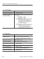
Appendix A: Performance Specification . . . . . . . . . . . . . . . .
Safety Standards . . . . . . . . . . . . . . . . . . . . . . . . . . . . . . . . . . . .
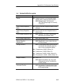
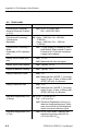
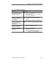
Electrical Specifications . . . . . . . . . . . . . . . . . . . . . . . . . . . . . .
A–1
A–1
A–2
Appendix B: User Service . . . . . . . . . . . . . . . . . . . . . . . . . . . . .
Fuse Replacement . . . . . . . . . . . . . . . . . . . . . . . . . . . . . . . . . . .
Battery Replacement . . . . . . . . . . . . . . . . . . . . . . . . . . . . . . . . .
Cleaning . . . . . . . . . . . . . . . . . . . . . . . . . . . . . . . . . . . . . . . . . . .
Exterior . . . . . . . . . . . . . . . . . . . . . . . . . . . . . . . . . . . . . . . .
Display Screen . . . . . . . . . . . . . . . . . . . . . . . . . . . . . . . . . . .
Interior . . . . . . . . . . . . . . . . . . . . . . . . . . . . . . . . . . . . . . . . .
LCD Display . . . . . . . . . . . . . . . . . . . . . . . . . . . . . . . . . . . . . . .
B–1
B–1
B–1
B–1
B–1
B–2
B–2
B–2
Index
iv
WFM 90 & WFM 91 User Manual
Table of Contents
List of Illustrations
Figure 1–1: Packing the Option 33 travel case . . . . . . . . . . .
1–11
Figure 1–2: Installed polarity of alkaline batteries . . . . . . .
1–13
Figure 1–3: Removing the NiCad battery pack . . . . . . . . . .
1–14
Figure 1–4: Installing the viewing hood . . . . . . . . . . . . . . . . .
1–15
Figure 1–5: Installing the desk stand . . . . . . . . . . . . . . . . . . .
1–16
Figure 2–1: WFM 90 keypad . . . . . . . . . . . . . . . . . . . . . . . . .
2–2
Figure 2–2: WFM 90 and WFM 91 side panels . . . . . . . . . .
2–5
Figure 2–3: On-screen readout messages . . . . . . . . . . . . . . .
2–8
Figure 3–1: NTSC waveform graticule . . . . . . . . . . . . . . . . .
3–10
Figure 3–2: PAL waveform graticule . . . . . . . . . . . . . . . . . . .
3–10
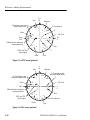
Figure 3–3: NTSC vector graticule . . . . . . . . . . . . . . . . . . . .
3–12
Figure 3–4: PAL vector graticule . . . . . . . . . . . . . . . . . . . . . .
3–12
Figure 3–5: Vector targets – NTSC
values (PAL values in parentheses) . . . . . . . . . . . . . . . . .
3–13
Figure 3–6: Differential gain and phase
measurement box . . . . . . . . . . . . . . . . . . . . . . . . . . . . . . . .
3–14
Figure 3–7: Audio graticule with –3 dB
headroom selected . . . . . . . . . . . . . . . . . . . . . . . . . . . . . . .
3–15
Figure 3–8: Audio graticule with +10 dB
headroom selected . . . . . . . . . . . . . . . . . . . . . . . . . . . . . . .
3–15
WFM 90 & WFM 91 User Manual
v
Table of Contents
vi
WFM 90 & WFM 91 User Manual
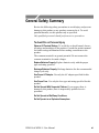
General Safety Summary
Review the following safety precautions to avoid injury and prevent
damage to this product or any products connected to it. To avoid
potential hazards, use this product only as specified.
Only qualified personnel should perform service procedures.
To Avoid Fire or Personal Injury
Observe All Terminal Ratings. To avoid fire or shock hazard, observe
all ratings and markings on the product. Consult the product manual
for further ratings information before making connections to the
product.
The common terminal is at ground potential. Do not connect the
common terminal to elevated voltages.
Replace Batteries Properly. Replace batteries only with the proper
type and rating specified.
Recharge Batteries Properly. Recharge batteries for the recommended
charge cycle only.
Use Proper AC Adapter. Use only the AC adapter specified for this
product.
Use Proper Fuse. Use only the fuse type and rating specified for this
product.
Do Not Operate With Suspected Failures. If you suspect there is
damage to this product, have it inspected by qualified service
personnel.
Do Not Operate in Wet/Damp Conditions.
Do Not Operate in an Explosive Atmosphere.
WFM 90 & WFM 91 User Manual
vii
General Safety Summary
Safety Terms and Symbols
Terms in This Manual. These terms may appear in this manual:
WARNING. Warning statements identify conditions or practices that
could result in injury or loss of life.
CAUTION. Caution statements identify conditions or practices that
could result in damage to this product or other property.
Terms on the Product. These terms may appear on the product:
DANGER indicates an injury hazard immediately accessible as you
read the marking.
WARNING indicates an injury hazard not immediately accessible as
you read the marking.
CAUTION indicates a hazard to property including the product.
Symbols on the Product. These symbols may appear on the product:
CAUTION
Refer to Manual
Double
Insulated
Battery Recycling
This product contains a Nickel Cadmium (NiCd) battery, which must
be recycled or disposed of properly. For the location of a local
battery recycler in the U.S. or Canada, please contact:
RBRC
Rechargeable Battery Recycling Corp.
P.O. Box 141870
Gainesville, Florida 32614
viii
(800) BATTERY
(800) 227-7379
www.rbrc.com
WFM 90 & WFM 91 User Manual
Preface
This manual is a guide for operators of the WFM 90 and WFM 91
Waveform, Vector, Picture, and Audio Monitor, and contains
instructions for practical use.
Throughout this manual, instrument controls and display readouts
appear in ALL CAPITALS.
Manual Overview
The following is a brief description of the content of the different
sections of this manual:
Getting Started provides a product description, a list of available
options and accessories, and information concerning the electrical
and mechanical installation of the instrument.
Operation Basics contains a functional description of instrument
operation and is followed by an operator familiarization tutorial.
Reference provides descriptions of each menu selection and also
describes the different graticules and how to use them to make basic
signal measurements.
Appendix A lists complete instrument specifications, both
electrical and mechanical.
Appendix B provides instructions for preventive maintenance of
the instrument.
WFM 90 & WFM 91 User Manual
ix
Preface
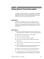
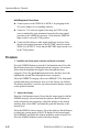
The WFM 90 Handheld Waveform, Vector, Picture, and Audio Monitor
x
WFM 90 & WFM 91 User Manual
Getting Started: Product Description
The Tektronix WFM 90 and WFM 91 is a handheld, self-contained,
rasterizing television waveform/vector/picture/audio monitor. The
instrument has a built-in LCD color display device and is powered
by batteries or by an AC adapter producing 12 VDC.
Applications
The WFM 90 and WFM 91 can be used in traditional in-house
applications of television production, post-production, and signal
transmission. The portability of this instrument allows it to be used
in non-traditional applications such as field production and system
maintenance.
Key Features
Rasterized waveforms and graticules shown on the built-in color,
4-inch diagonal TFT LCD display with viewing angle adjustment
Instrument is powered by batteries or a DC adapter
Menu-assisted monitoring operation
Video and audio signal input/output capability
Waveform, Vector, Picture, Audio, and Waveform-in-Picture
display modes
Line Select mode which allows the selection of any single line of
video for viewing
Time-out mode which shuts off power to the display backlight
and/or the instrument when the instrument is not in use
Signal level alarm mode for the waveform and audio displays
Preset menu to store/recall the front panel and menu setup
Instrument readjustment is performed entirely from the keypad
(the adjustment procedures are located in the service manual)
WFM 90 & WFM 91 User Manual
1–1
Getting Started: Product Description
Description of Features
Rasterized Color LCD Display
The WFM 90 and WFM 91 uses a proprietary rasterizer which
displays analog waveforms or vectors on the color 4-inch diagonal,
backlit thin-film transistor (TFT) LCD raster display, simultaneously
with the appropriate measurement graticules. A viewing-angle
control for the display permits optimal signal viewing from different
positions.
The LCD display will retain an image if the instrument is left on in
one display mode for an extended period of time. This is typical for
the LCD display device. The retained image will fade over time, and
the fading can be accelerated by leaving the instrument turned off.
CAUTION. LCD Display Image Retention
To prevent image retention in the LCD display, enable the backlight
time-out mode or turn the instrument off if the monitor is going to be
left alone for more than two hours.
Battery or AC Adapter Operation
The instrument can be powered by six C-cell batteries, (alkaline or
NiCad) by an internally rechargable NiCad battery pack, or by an AC
adapter wall unit with a negative center lead producing 12 VDC. The
rechargeable NiCad battery pack is automatically recharged when the
12 VDC adapter is plugged into the instrument, while instrument
power is on or off.
NOTE. To avoid uninterupted operation when using the wall adapter,
be sure that the batteries are installed in the instrument.
1–2
WFM 90 & WFM 91 User Manual
Getting Started: Product Description
NOTE. Only the NiCad battery pack recharges in the instrument.
Alkaline batteries are not recharged. The message LOW BAT is
displayed in the on-screen readout when the batteries get critically
low on power.
Menu-Assisted Monitoring Operation
The menus use a combination of on-screen readout and multi-use
buttons, in conjunction with the Arrow Buttons, to control most of
the monitoring functions. Menus are entered by pressing one of the
MENU, CONFIG, or LINE SEL buttons. Menus are exited by pressing
the entry button for the open menu, or by entering another menu.
Video and Audio Input/Output
The WFM 90 and WFM 91 displays signals from the one channel of
composite video input, or from the one channel of audio input. An
external reference input allows the use of an external sync signal.
The video and external reference inputs are BNC connectors, each
with a rear-panel switch providing the choice of an internal 75 W
signal termination, or an unterminated high-impedance input. The
audio input is a standard 3-pin XLR connector.
The video output is a BNC connector that will drive a remote
monitor or video switcher. The audio output is a mini-headphone
stereo jack which outputs the mono input signal to both stereo
channels. The audio volume is fixed for each reference level. The
larger the displayed signal, the louder the volume.
Waveform Display Mode
The Waveform display mode provides a voltage-versus-time display
of the video signal with three standard sweep rates: 1H (5 s/division), 2H (10 s/division), and 2F (two field). Each line-rate sweep
can be magnified X10 to sweep rates: 1H Mag (0.5 s/division), and
2H Mag (1 s/division). The 2F sweep is magnified by approximately X20.
Vertical gain is fixed at X1 or X5, or variable from 45% to 155%.
The gain setting tracks between the Waveform and Vector display
WFM 90 & WFM 91 User Manual
1–3
Getting Started: Product Description
modes. The signal filters are Flat (no filter) and Luminance
(low-pass filtered). The Line Select mode enables the selection of a
single line of video for display.
Vector Display Mode
The Vector display mode presents an XY plot of the demodulated
chrominance phase and amplitude portion of the video signal. The
vector angle represents chrominance phase, and the distance from the
center represents chrominance amplitude. The vector display is
useful when making differential gain and phase measurements.
A full 360_ phase shifter, and 75% and 100% color bar settings are
provided. Vector gain is fixed at X1 or X5, or variable from 45% to
155%. The gain setting tracks between the Waveform and Vector
display modes. The +V mode (PAL only) overlays the –V axis on the
+V axis to check the PAL system color encoders.
Picture Display Mode
The Picture display mode provides an unprocessed full color display
of the composite video signal. The NTSC Safe Action and Safe Title
areas, as well as the PAL Safe Area can be highlighted. The vertical
interval portion of the signal can be viewed by vertically shifting the
display. Controls for adjusting the hue and color of the picture
display are provided.
Audio Display Mode
The Audio display mode provides a voltage-versus-time display of a
single audio channel. The audio voltage is displayed on the vertical
scale with time on the horizontal scale at a two-field sweep rate.
Audio reference levels can be set to –10, 0, 4, or 8 dBu, with an
additional level available for microphone checks. The audio
headroom reference level can be set to –3 dB or +10 dB, and is for
audio signals below or above the reference level, respectively.
Waveform-in-Picture Display Mode
The Waveform-in-Picture (WIP) display mode provides a 1/4-screensized window over the Picture display for any one of the Waveform,
1–4
WFM 90 & WFM 91 User Manual
Getting Started: Product Description
Vector, or Audio displays. The WIP window can be positioned to any
one of the four corners of the display. The Arrow Buttons retain their
default function for the display mode in the WIP window.
Line Select Mode
The Line Select mode enables the user to select any line of video for
viewing in either the Waveform or Vector display modes. The
desired line can be selected from either all video fields or from
alternating fields. With two-field sweep selected in the Waveform
display mode, the selected line is highlighted in the field display.
Time-Out Mode
When the Time-out mode is enabled, power is turned off to the
display backlight and/or the instrument when the front panel has not
been in use for a menu-selected length of time.
Amplitude Alarm Mode
The Amplitude Alarm mode provides automatic signal level
checking in the Waveform and Audio display modes. In the
Waveform display mode, the portion of the waveform exceeding the
100 IRE (1.0 V PAL) graticule line is highlighted. In the Audio
display mode, the portion of the waveform exceeding the selected
reference level is highlighted.
Preset Menu
The Preset menu allows the user to store the current instrument front
panel and menu settings for future use. In addition, there is a menu
selection which sets the front panel and menu settings back to a
factory-set default. These default settings are listed on page 3–7.
Instrument Readjustment
The WFM 90 and WFM 91 can be adjusted entirely from the front
panel after entering the Calibration menu. The instrument should
only be adjusted by qualified personnel. The service manual contains
the instructions for readjusting the instrument.
WFM 90 & WFM 91 User Manual
1–5
Getting Started: Product Description
More Information
Instrument options and accessories, as well as ordering
information, are listed beginning on page 1–7.
Battery operation is discussed beginning on page 1–12.
A tutorial covering basic instrument operation starts on page
2–11.
Detailed menu descriptions begin on page 3–1.
A complete listing of instrument performance specifications is
located in Appendix A.
1–6
WFM 90 & WFM 91 User Manual
Options and Accessories
This section lists the options which can be ordered as well as the
standard and optional accessories for the WFM 90 and WFM 91.
Ordering information is given at the end of the accessories list.
Options
The options listed below can be ordered with the WFM 90 and
WFM 91. Listed with the power adapter options are the Tektronix
part numbers to be used when ordering replacements.
Option A1
220 V Wall Unit Power Adapter, European TUV
(119-4540-00)
Option A2
240 V Wall Unit Power Adapter, UK
(119-4541-00)
Option A3
240 V Wall Unit Power Adapter, Australia
(119-4542-00)
Option A6
100 V Wall Unit Power Adapter, Japan
(119-4539-00)
Option M2 5 years Warranty/Remedial Service
Option M8 4 Calibration/Performance Tests
Option 33
Travel-line package including:
NiCad Battery Pack
Viewing Hood
Desk Stand
Carrying Case for a WFM 90 or WFM 91 and
a TSG 90–Series signal generator
WFM 90 & WFM 91 User Manual
1–7
Getting Started: Options and Accessories
Accessories
Standard accessories are shipped with every instrument while
optional accessories must be ordered. Listed below are the standard
and optional accessories for the WFM 90 and WFM 91 along with
the Tektronix part number to be used when ordering.
Standard Accessories
1
User Manual (070-8968-XX)
1
120 V Wall Unit Power Adapter, North American
(119-4538-00)
1
Carrying Pouch (016-1330-00)
Optional Accessories
Service Manual (070-8969-XX)
NiCad Battery Pack (146-0107-00)
Instrument Desk Stand (386-6787-00)
Viewing Hood (011-0167-00)
Carrying Case for the WFM 90 and WFM 91 and a TSG 90–Series
signal generator (016-1344-00)
Backlight Replacement Kit (150-0215-00)
Ordering
Options and accessories for the WFM 90 and WFM 91 can be
ordered with the instrument, or purchased through a Tektronix field
office or distributor. When ordering, include both the option or part
number and the description of the option or accessory.
1–8
WFM 90 & WFM 91 User Manual
Installation
This section gives instructions for the mechanical and electrical
installation of the WFM 90 and WFM 91. Included are directions for
the packaging of the instrument for shipment.
Instrument Packaging
Unpacking
Save the shipping carton and packing materials in case it becomes
necessary to ship the instrument to a Tektronix Service Center for
service or repair.
Check that the following standard accessories are included:
User Manual
120 V Wall Unit Power Adapter, North American
Carrying Pouch
If the instrument was ordered with the travel case (Option 33), the
instrument was packaged in the travel case for shipment. Follow the
instructions below for repackaging the instrument for shipment.
Packaging for Shipment
If you ship an instrument to a Tektronix Service Center, follow these
packaging instructions:
1. Attach a tag to the instrument showing: the owner, complete
address and phone number of someone at your firm who can be
contacted, the instrument serial number, and a description of the
required service.
WFM 90 & WFM 91 User Manual
1–9
Getting Started: Installation
2. Package the instrument in the original packaging materials. If the
original packaging materials are not available, follow these
directions:
a. Obtain a carton of corrugated cardboard having inside
dimensions six or more inches greater than the dimensions of
the instrument. Use a shipping carton that has a test strength
of at least 250 pounds.
b. Place the instrument in its carrying pouch or surround the
instrument with a protective bag.
c. Pack dunnage or urethane foam between the instrument and
the carton. If using Styrofoam kernels, overfill the box and
compress by closing the lid. There should be three inches of
tightly packed cushioning on all sides of the instrument.
3. Seal the carton with shipping tape, industrial stapler, or both.
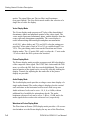
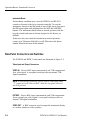
Travel Case
The optional travel case (Option 33) is used to safely hold the
WFM 90 or WFM 91 and its accessories while traveling between
different locations. The travel case was designed to also provide
room for a companion TSG 90–Series handheld generator. Figure 1–1
illustrates the use of the compartments within the travel case.
1–10
WFM 90 & WFM 91 User Manual
Getting Started: Installation
1
2
3
4
ÎÎÎÎÎÎ
ÎÎÎÎÎÎ
ÎÎÎÎÎÎ
ÎÎÎÎÎÎ
ÎÎÎÎÎÎÎÎÎÎÎÎÎÎ
ÎÎÎÎÎÎ
ÎÎÎÎÎÎÎÎÎÎÎÎÎÎ
ÎÎÎÎÎÎ
ÎÎÎÎÎÎ
ÎÎÎÎÎÎÎÎ
ÎÎÎÎÎÎÎÎ
ÎÎÎÎÎÎÎÎ
5
6
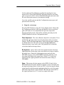
Figure 1–1: Packing the Option 33 travel case
1
The pouch in the cover of the travel case holds signal cables and the
user manual(s) for the instrument(s).
2
This compartment holds the WFM 90 or WFM 91 instrument, with
the viewing hood slipping around the instrument.
3
This compartment holds the spare batteries for the WFM 90 or
WFM 91.
4
This compartment holds the spare batteries for the TSG 90–Series.
5
This compartment holds the TSG 90–Series instrument, the desk
stand, and the carrying straps.
6
This compartment holds the AC adapter(s).
WFM 90 & WFM 91 User Manual
1–11
Getting Started: Installation
Electrical Installation
Power Source
The WFM 90 and WFM 91 are designed to operate from either six
C-cell batteries, alkaline or rechargeable NiCad, or from an AC
adapter wall unit producing 12 VDC.
CAUTION. DC Power Source
To avoid possible damage to the instrument circuitry when using a
DC power source other than the supplied AC adapter, ensure that the
DC source is a negative-ground 11 – 18 V system with a negative
center lead. The DC source should be able to provide 12 W of power.
Battery Operation
The rechargeable NiCad batteries are automatically recharged when
the 12 VDC adapter is plugged into the instrument. The batteries are
recharged while instrument power is on or off. The battery charge
time is 6.5 hours when the instrument is off, and 20 hours while the
instrument is on. The WFM 90 and WFM 91 shifts into a safe
trickle-charge mode, that can run indefinitely, when the NiCad
batteries are fully charged.
The message LOW BAT is displayed on-screen when the remaining
battery power cannot guarantee reliable instrument operation. The
length of time the WFM 90 and WFM 91 will continue to operate
after this message is displayed is dependent on the current operating
mode of the instrument.
For optimal battery life and capacity, use the rechargeable NiCad
battery pack in full charge/discharge cycles. In other words, fully
discharge the battery pack before recharging, and then charge the
battery pack until it is fully charged. A new battery pack will take a
few charge/discharge cycles to reach full capacity.
1–12
WFM 90 & WFM 91 User Manual
Getting Started: Installation
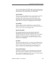
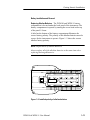
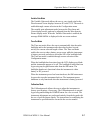
Battery Installation and Removal
Replacing Alkaline Batteries. The WFM 90 and WFM 91 battery
compartment is located under the back panel of the instrument. The
battery compartment is opened by turning the screw head at the top
of the panel 1/4 turn.
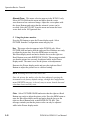
A label on the bottom of the battery compartment illustrates the
correct battery polarity. The polarity of the alkaline batteries must be
correct for the instrument to operate. Figure 1–2 shows the correct
alkaline battery polarity.
NOTE. Replacement of Alkaline Batteries
Always replace all of the alkaline batteries at the same time when
replacing discharged batteries.
Figure 1–2: Installed polarity of alkaline batteries
WFM 90 & WFM 91 User Manual
1–13
Getting Started: Installation
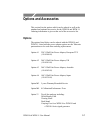
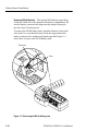
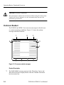
Replacing NiCad Batteries. The optional NiCad battery pack has a
connector which fits on the jumper in the battery compartment. Be
sure the battery connector tab snaps onto the jumper housing to
prevent a loss of battery power.
To remove the NiCad battery pack, grasp the batteries close to the
wire leads. Use your thumb to press in on the top portion of the
battery connector tab, and then pull gently upwards. Figure 1–3
shows how to remove the NiCad battery pack.
Grasp wire
Press
Figure 1–3: Removing the NiCad battery pack
1–14
WFM 90 & WFM 91 User Manual
Getting Started: Installation
Operational Jumpers
The only operational modifications made to this monitor are done
through the menu system. There are no internal jumper settings for
modifying the operational configuration of the instrument.
Mechanical Installation
The WFM 90 and WFM 91 are offered with a viewing hood and desk
stand as optional accessories that enhance its on-site use. The
installation of these accessories is described below.
Viewing Hood
The optional viewing hood allows the user to readily view the
instrument display in well-lighted situations. The hood is attached to
the instrument by first applying the supplied Velcro strips to the
sides of the instrument, and then pressing the flaps of the viewing
hood onto the strips as shown in Figure 1–4.
Figure 1–4: Installing the viewing hood
WFM 90 & WFM 91 User Manual
1–15
Getting Started: Installation
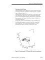
Desk Stand
The optional desk stand provides the user with a stable means to hold
the instrument upright on a flat surface. The prongs of the stand are
inserted into the holes in the back of the instrument as illustrated in
Figure 1–5.
Figure 1–5: Installing the desk stand
1–16
WFM 90 & WFM 91 User Manual
Operation Basics: Functional Overview
This section describes the WFM 90 and WFM 91 controls and
connectors. Descriptions of special operating modes begin on page
2–6. A tutorial which guides you through a procedure exercising the
different functions of the instrument begins on page 2–11. Menu
operation is detailed in Using the Menus, starting on page 3–1.
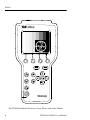
Keypad Controls
The keypad (front panel) is illustrated in Figure 2–1.
Power Switch
ON. The ON button toggles the instrument power on and off. The
current instrument keypad and menu selections are saved when the
instrument is turned off using this button. The instrument configuration is not saved if the power source is removed before the
instrument is turned off with this button.
Display Mode Selection
WFM. Pressing the WFM button enters the Waveform display mode.
VECT. Pressing the VECT button enters the Vector display mode.
AUDIO. Pressing the AUDIO button enters the Audio display mode.
PIX. Pressing the PIX button enters the Picture display mode.
WIP. Pressing the WIP button enters the Waveform-in-Picture
display mode. The previously selected display mode, other than
Picture, is shown in a 1/4-screen-sized window that overlays the
Picture display.
WFM 90 & WFM 91 User Manual
2–1
Operation Basics: Functional Overview
Figure 2–1: WFM 90 keypad
2–2
WFM 90 & WFM 91 User Manual
Operation Basics: Functional Overview
Menu Control
Menu operation and selections are detailed in Using the Menus
starting on page 3–1.
MENU. Pressing the MENU button toggles the Operating menu on
and off. The Operating menu contains monitoring selections which
are specifically related to the currently selected display mode.
Operating menu selections include signal gain and filtering, audio
reference levels, and safe action and title outlines.
CONFIG. Pressing the CONFIG button toggles the Configuration
menu on and off. The Configuration menu contains selections which
control overall instrument monitoring operation. Configuration menu
contents include signal and display controls such as brightness and
variable gain. Special modes for monitoring signal amplitude and
managing the battery power consumption are enabled in this menu.
LINE SEL. Pressing the LINE SEL button toggles the Line Select
mode on and off and displays the Line Select menu.
Bezel Buttons. The four unlabeled buttons directly below the display
are referred to as the Bezel Buttons. These buttons are used for
making menu selections and are only enabled while menus are
displayed on screen.
Arrow Buttons
The function of the Arrow Buttons is dependent on the current state
of the instrument. For the Waveform and Audio display modes, they
control signal positioning. For the Vector display mode, they control
vector phase, with the Y and B buttons providing fine adjustment,
and the A and " buttons providing coarse adjustment.
The Arrow Buttons retain their default function for the reduced
display when the Waveform-in-Picture display mode is selected.
When the Configuration menu is displayed, the Y and B buttons
operate the menu category selection, while the A and " buttons
retain their default function for the current display mode.
WFM 90 & WFM 91 User Manual
2–3
Operation Basics: Functional Overview
Instrument Reset
Extraordinary conditions may cause the WFM 90 and WFM 91
controls to become locked or to respond erratically. To reset the
instrument, first press the ON button to turn off the power, then press
the ON button again while holding down the WIP and LINE SEL
buttons. The instrument should return to normal operation with the
keypad controls and menu selections assigned to the factory-set
defaults.
If this reset does not return the instrument to normal operation,
contact your Tektronix field office or call Tektronix at the phone
number listed in the front of this manual.
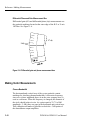
Side-Panel Connectors and Switches
The WFM 90 and WFM 91 side panels are illustrated in Figure 2–2.
Video Input and Output Connectors
VIDEO IN. Passive BNC input, unterminated, and 75 W compensated
for a video signal. A rear-panel switch provides an internal 75W
signal termination.
NOTE. A loop-through connector can be used by connecting a BNC
“T” connector to the Video In BNC. Slide the rear panel switch in
the HI-Z position.
EXT REF. Passive BNC input, unterminated, and 75 W compensated
for an external sync video signal. A rear-panel switch provides an
internal 75 W signal termination.
VIDEO OUT. A BNC connector used to output the instrument display
to a remote monitor or video switcher.
2–4
WFM 90 & WFM 91 User Manual
Operation Basics: Functional Overview
Audio Input and Output Connectors
AUDIO IN. A standard three-pin XLR connector for a single channel
of audio input.
DC IN 11-18V
Figure 2–2: WFM 90 and WFM 91 side panels
WFM 90 & WFM 91 User Manual
2–5
Operation Basics: Functional Overview
Audio Out. A standard stereo mini-headphone jack for the output of
the audio input signal. The mono input signal is heard on both stereo
channels. The audio volume is fixed for each reference level. The
larger the displayed signal, the louder the volume.
DC Power Input Connector
DC IN 11 – 18 V. A 2 mm plug which accepts a 12 VDC power input
using a negative center lead.
CAUTION. DC Power Source
To avoid possible damage to the instrument circuitry when using a
DC power source other than the supplied AC adapter, ensure that the
DC source is a negative-ground 11 – 18 V system with a negative
center lead. The DC source should be able to provide 12 W of power.
Special Operating Modes
Amplitude Alarm Mode
The Amplitude Alarm mode provides a means for automatic
monitoring of the signal amplitude for the Waveform and Audio
displays. The mode is enabled through a menu selection in the
Configuration menu.
For the Waveform display mode, the portion of the signal exceeding
the 100 IRE (1.0 V PAL) graticule line is highlighted. For the Audio
display mode, the portion of the signal exceeding the menu-selected
reference level is highlighted. The highlighted portion of the signal is
also visible in the Waveform-in-Picture (WIP) display mode.
2–6
WFM 90 & WFM 91 User Manual
Operation Basics: Functional Overview
Variable Gain Mode
The Variable Gain mode allows the user to vary signal gain for the
Waveform and Vector displays between 45% and 155%. The mode is
enabled through a menu selection in the Configuration menu.
The variable gain adjustment tracks between the Waveform and
Vector display modes, and can be adjusted from the Waveform-inPicture display mode. When the Variable Gain mode is enabled, the
message GAIN UNCAL is displayed in the on-screen readout.
Time-Out Mode
The Time-out mode allows the user to automatically shut down the
backlight and/or the instrument after there has been no keypad
activity for a menu-selected length of time. The Time-out mode
enables the user to reduce battery power usage while the instrument
is battery powered, and also to extend the life of the backlight bulb.
The Time-out mode is enabled through a menu selection in the
Configuration menu.
When the backlight has been timed out, the LCD display goes blank
and the instrument appears to be off. The backlight is turned back on
by pressing any keypad button other than the ON button. The
backlight shutdown is functional when the instrument is either
battery or DC powered.
When the instrument power has been timed out, the ON button must
be pressed to turn the instrument back on. The instrument power
shutdown is only functional when the instrument is battery powered.
Calibration Mode
The Calibration mode allows the user to adjust the instrument to
factory specifications, if necessary. The Calibration mode is entered
by pressing and holding the CONFIG button for a few seconds. The
instrument adjustments are performed entirely from the keypad with
the use of specified input signals. The instructions for readjusting the
instrument to specifications are located in the service manual.
WFM 90 & WFM 91 User Manual
2–7
Operation Basics: Functional Overview
CAUTION. Instrument Adjustment
Do not attempt to adjust the instrument without using the instructions
listed in the service manual, or your instrument may not meet the
published specifications.
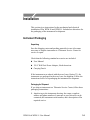
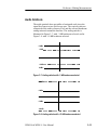
On-Screen Readout
The WFM 90 and WFM 91 use on-screen messages to alert the user
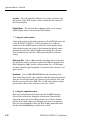
to certain monitoring conditions. Figure 2–3 shows the readout
messages and their locations.
1
4
GAIN UNCAL
SYNC
MISSING
100
2
3
EXT REF
10uS/DIV
VX.XX
5
LOW BAT
6
80
60
40
20
0
–20
–40
Figure 2–3: On-screen readout messages
Readout Description
1
2–8
The GAIN UNCAL message appears in the Waveform, Vector, and
Waveform-in-Picture display modes when the Variable Gain mode
has been turned on.
WFM 90 & WFM 91 User Manual
Operation Basics: Functional Overview
2
The EXT REF message appears in the Waveform and Vector display
modes when the video signal is locking to an external video
reference signal.
3
The sweep rate is only displayed in the Waveform display mode.
There is no sweep rate readout when 2 Field sweep is selected.
4
The MISSING SYNC message appears in all video display modes
when the signal reference has been lost.
5
The instrument software version number is displayed when the
Configuration menu is open with the DISPLAY category selected.
6
The LOW BAT message is displayed when the instrument is battery
operated and the remaining battery power has reached a critically
low level. The remaining length of time that the instrument can be
operated reliably is dependent on the current operating mode.
WFM 90 & WFM 91 User Manual
2–9
Operation Basics: Functional Overview
2–10
WFM 90 & WFM 91 User Manual
Tutorial
The following tutorial guides you through a procedure which
exercises the different functions of the WFM 90 and WFM 91. The
procedure is designed for operator familiarization and for checking
basic instrument operation (not measurement quantities or specifications). The tutorial is written with the assumption that you have read
the Functional Overview section which starts on page 2–1.
If performing this procedure reveals improper instrument operation,
first check the operation of the associated equipment. If the
associated equipment is operating normally, refer the WFM 90 or
WFM 91 to qualified service personnel for repair or adjustment.
Required Equipment
The following equipment is required to perform this procedure:
1. Television/Audio Signal Generator with:
Composite Color Bars
Black Burst or comparable signal with burst and sync
Audio tone at adjustable levels
For example:
Tektronix TSG 95 Pathfinder NTSC/PAL Signal Generator
2. Coaxial Cable, 75 W (2)
For example:
42-inch RG59U (Tektronix Part No. 012-0159-00)
3. Audio Cable, 3-pin Male-to-Female XLR
For example:
3-foot cable (Switchcraft Part No. SC3XXJ)
WFM 90 & WFM 91 User Manual
2–11
Operation Basics: Tutorial
Initial Equipment Connections
H Connect power to the WFM 90 or WFM 91 by plugging in the
AC power adapter or by installing batteries.
H Connect a 75% color bar signal (with setup for NTSC) of the
correct standard for your instrument from the television signal
generator to the VIDEO IN connector. Verify that the VIDEO IN
input switch is set to the 75 W position.
H Connect a black burst or other signal with burst and sync from
the television signal generator to the EXT REF connector on the
WFM 90 or WFM 91. Verify that the EXT REF input switch is set
to the 75 W position.
Procedure
1. Initialize the front-panel controls and menu selections
Press the CONFIG button to enter the Configuration menu. Press the
Bezel Button below the Configuration menu categories a few times.
Notice that the highlight bar toggles down through the menu
categories. Press the Y and B buttons and notice that they move the
highlight bar up and down through the menu categories.
Select the PRESETS category, then select DEFAULT. The front-panel
controls and menu selections are now set to the factory-set defaults.
The display should be a two-line waveform monitor display centered
on the graticule baseline.
2. Adjust the display
Enter the Configuration menu. Notice that the menu opened with the
INTENS category selected and that the right two Bezel Buttons are
ready to adjust the trace intensity. Adjust the display to the desired
intensity, then select GRAT and adjust the graticule intensity to the
desired level.
Select the DISPLAY menu category. Press the right two Bezel Buttons
to adjust the viewing angle of the LCD display to the desired angle.
Select BRIGHT and adjust the display brightness to the desired level.
Press the CONFIG button to remove the menu display.
2–12
WFM 90 & WFM 91 User Manual
Operation Basics: Tutorial
3. Using the waveform monitor
Press the MENU button to enter the Operating menu. The current
selection for each monitoring function is highlighted. Pressing the
Bezel Button below each function will toggle the highlight bar
through the different menu selections.
X1/X5 Gain. Press the left Bezel Button and notice that X5 is
highlighted and that the waveform is vertically amplified. Use the
Y and B buttons to view the entire signal. Select X1 and return the
signal to the graticule baseline. The gain setting affects both the
Waveform and Vector displays since they track together.
Filter. Press the Bezel Button below the FILTER selection and notice
that LUM is highlighted and that the display changes to show only the
luminance portion of the signal. Press the Bezel Button again to
return the filter selection to FLAT.
Sweep. Press the Bezel Button below the SWEEP selection and
notice that 2F is highlighted and that the waveform changes to a
two-field display. Press the Bezel Button again and notice that 1H is
highlighted and that the waveform changed to a one-line display and
that 5 uS/DIV is displayed in the on-screen readout. Return the sweep
rate to 2H (two line).
MAG. Press the right Bezel Button and notice that ON is highlighted
and that the waveform is horizontally amplified. The sweep rate
readout should read 1 uS/DIV. Use the A and " buttons to view the
entire waveform. Select MAG OFF from the menu and center the
waveform on the display.
DC Restorer. Enter the Configuration menu and select the INPUT
category. Notice that there is a menu selection which allows you to
change the DC restorer speed between FAST and SLOW.
WFM 90 & WFM 91 User Manual
2–13
Operation Basics: Tutorial
Signal Reference. Press the Bezel Button below the menu selection
labeled REF. Notice that EXT is highlighted and that EXT REF
appears in the on-screen readout. Remove the cable from the EXT
REF input and notice that the waveform free-runs and that the
message MISSING SYNC appears in the on-screen readout. Return
the reference selection to INT.
Line Selection. Press the LINE SEL button to enter the Line Select
mode. Notice that the selected line number (Line 17) is displayed in
the bar over the right two Bezel Buttons and that it is being displayed
from ALL video fields. Line 17 is displayed on the left, with Line 18
displayed on the right in the two-line sweep. Use the Bezel Buttons
to select Line 30 for display.
Press the MENU button to enter the Operating menu and select
2F SWEEP. Notice that the selected line is highlighted in both field
displays. Press the LINE SEL button to return to the Line Select
menu. Press the left Bezel Button to select 1 OF 2 FIELDS. Notice
that an additional menu selection of ALT FIELD appears, that the line
number display now includes the field number, and that the selected
line is now highlighted in only the left field display. Press the
ALT FIELD Bezel Button and notice that the field number readout
changes and that the highlight bar in the waveform toggles between
the two fields.
Turn off the Line Select mode by pressing the LINE SEL button.
Enter the Operating menu and select 2H SWEEP.
Variable Gain. Enter the Configuration menu and select the VAR
GAIN category. Select VAR GAIN ON and notice that a bar appears
over the right two Bezel Buttons labeled VAR ADJUST and that the
message GAIN UNCAL appears in the on-screen readout.
Press one of the right two Bezel Buttons just once. Notice that the
Configuration menu category list over the left Bezel Button has been
replaced with a single label of CONFIG to provide full viewing of the
waveform, and that Up/Down arrows appear in the bar over the right
two Bezel Buttons signifying that they are enabled to adjust the
signal gain. The menu category list can be restored by pressing the
left Bezel Button or by turning off the variable gain.
2–14
WFM 90 & WFM 91 User Manual
Operation Basics: Tutorial
Use the right two Bezel Buttons to adjust the signal gain to any
desired level. Select VAR GAIN OFF and notice that the waveform
gain is restored to 100%. Select VAR GAIN ON again and notice that
the waveform gain returns to your adjusted setting.
Leave the variable gain on and the Configuration menu open, and
proceed to the next step.
4. Using the vectorscope
Press the VECT button to enter the Vector display mode. Notice that
the Configuration menu is still open and that the vector waveform
gain is the same as it was adjusted in the previous step in the
Waveform display mode. Turn off the variable gain and press the
CONFIG button to exit the Configuration menu.
Phase Adjustment. The Arrow Buttons adjust the vector phase. Press
and hold the Y button. Notice how fast the phase of the waveform
changes. Press and hold the " button. Notice that the phase changes
at a much faster rate. The same is true for the B and A buttons.
Adjust the burst vector back to the 180° graticule line so that the
vector dots land in the target boxes.
Bar Amplitude. Select 100% color bars output from the television
signal generator. Notice that vector waveform is too large to land in
the target boxes. Enter the Configuration menu and select the
VECTOR category. Select 100% BARS and notice that the vector
waveform now lands in the target boxes. Select 75% color bars
output from the signal generator and return the menu setting to
75% BARS.
Setup. This menu selection appears in the WFM 90 only. Select
SETUP NO from the menu and notice that the vector waveform does
not land in the target boxes. Select an NTSC color bar signal without
setup from the signal generator and notice that the vector dots again
land in the target boxes. Select SETUP YES from the menu and set
the signal generator for a 75% color bar output with setup.
WFM 90 & WFM 91 User Manual
2–15
Operation Basics: Tutorial
Alternate Phase. This menu selection appears in the WFM 91 only.
Select ALT PH ON from the menu and notice that the vector
waveform now has a mirrored image. Adjust the vector phase with
the Arrow Buttons and notice that the mirrored vectors can be
overlaid. Select ALT PH OFF from the menu and return the burst
vector back to the 180° graticule line.
5. Using the picture monitor
Press the PIX button to enter the Picture display mode. Select
PICTURE from the Configuration menu category list.
Hue. This menu selection appears in the WFM 90 only. Select
PICTURE HUE and notice that the right two Bezel Buttons are ready
to adjust the picture hue. Press the WFM button to enter the
Waveform display mode and notice that the bar over the right two
Bezel Buttons now reads ENTER PIX TO ADJ. This message reminds
you that the picture hue can only be adjusted while in the Picture
display mode. The same is true for the picture color adjustment.
Return to the Picture display mode and press the right two Bezel
Buttons to adjust the picture hue to a desired setting.
NOTE. Resetting the Picture Hue and Color
Once the picture hue and/or color has been adjusted, resetting the
instrument to the factory default settings, through the Configuration
menu PRESETS category, is the only way to ensure that the hue and
color have been correctly reset.
Color. Select PICTURE COLOR and notice that the right two Bezel
Buttons are ready to adjust the picture color. Press the WFM button to
enter the Waveform display mode and notice that the bar over the
right two Bezel Buttons now reads ENTER PIX TO ADJ. This
message reminds you that the picture color can only be adjusted
while in the Picture display mode.
2–16
WFM 90 & WFM 91 User Manual
Operation Basics: Tutorial
Return to the Picture display mode and press the right two Bezel
Buttons to adjust the picture color to a desired setting.
Select PRESETS from the Configuration menu category list and
select DEFAULT to reset the picture hue and color back to their
proper settings. Select the Picture display mode.
Safe Action. This menu selection appears in the WFM 90 only. Press
the MENU button to enter the Operating menu. Select ACTION ON
and notice that the Safe Action area is outlined on the display.
Safe Title. This menu selection appears in the WFM 90 only. Select
TITLE ON and notice that the Safe Title area is now also outlined.
Safe Area. This menu selection appears in the WFM 91 only. Press
the MENU button to enter the Operating menu. Select SAFE AREA
ON and notice that the Safe Area is outlined on the display.
Vertical Shift. Select V SHIFT ON and notice that the display has
shifted vertically so that you can see the vertical interval portion of
the video signal.
6. Using the waveform-in-picture (WIP) display
Press the WIP button to enter the Waveform-in-Picture (WIP) display
mode. Notice that the Waveform display is shown in the 1/4-screensized window over the Picture display, and that the Picture display
does not show the Safe Area(s) or the vertical shift which were left
on in the Picture display mode. The Waveform display is shown in
the WIP window because it was the last display mode selected in the
previous steps.
Press the Arrow Buttons and notice that they still have control of
signal positioning. You have access to all of the Waveform display
controls except those located in the Operating menu. The Operating
menu selections for any display mode can only be changed while that
display mode is selected.
WFM 90 & WFM 91 User Manual
2–17
Operation Basics: Tutorial
Location. Press the right Bezel Button a few times and notice that
the location of the WIP window rotates around the four corners of
the Picture display.
Display Mode. The left three Bezel Buttons allow you to change
which display mode is shown in the WIP window.
7. Using the audio monitor
Connect the output of the audio generator to the AUDIO IN connector
on the WFM 90 or WFM 91. Set the generator for a 0 dB tone
output. Press the AUDIO button to select the Audio display mode.
Notice that the audio waveform is free-running and that the audio
graticule has solid lines labeled 0 dBu representing the reference
level and dashed lines labeled –3dB representing the headroom
setting.
Reference dBu. Select 4 dBu from the Operating menu. Notice that
the amplitude of the waveform is reduced and that the graticule line
label changed to 4 dBu. Set the audio generator for a +4 dB output
and notice that the signal amplitude is returned to the reference level
graticule line.
Headroom. Select 10dB HEADROOM from the Operating menu.
Notice that the graticule scale expands so that the headroom graticule
lines are now located outside the reference level graticule lines, and
that they are now labeled +10dB. The +10 dB setting allows signals
greater than 3 dB over the reference level to be viewed.
8. Using the amplitude alarm
Enter the Configuration menu and select the ALARMS category.
Select ON to turn on the Amplitude Alarm mode. Return to the
Operating menu and select 0 dBu reference level. Notice that the
portion of the audio signal exceeding the reference level graticule
lines has been highlighted. Enter the WIP display mode and notice
that the alarm highlighting is visible there as well.
2–18
WFM 90 & WFM 91 User Manual
Operation Basics: Tutorial
Select the Waveform display mode to be displayed in the WIP menu.
Use the Y button to position the waveform above the 100 IRE
graticule line. Notice that the portion of the signal exceeding the
100 IRE graticule line is highlighted.
9. Using the presets
Enter the Configuration menu, select the PRESETS category and
then select STORE. Now select DEFAULT from the menu and notice
that the instrument returned to the Waveform display mode which is
the factory-set default mode. Return to the Presets menu and select
RECALL. Notice that the instrument returns to the WIP display mode
with the Waveform display mode displayed with the Amplitude
Alarm on, which was the instrument setting when you stored your
preset previously.
10. Using the time-out mode
Select the TIME-OUT category from the Configuration menu. Select
2 MIN from the BACK LT menu choices. Wait two minutes and notice
that the display goes blank. Press any Bezel Button and notice that
the display returns. Pressing any keypad button except the ON button
will turn the backlight back on.
The SHUTDOWN menu selections turn off instrument power after the
menu-selected length of time. Once the instrument has timed out, it
is turned back on by pressing the ON button.
This concludes the operator familiarization tutorial.
WFM 90 & WFM 91 User Manual
2–19
Operation Basics: Tutorial
2–20
WFM 90 & WFM 91 User Manual
Reference: Using the Menus
This section begins with general information on menu operation.
Descriptions of each menu selection begin on the following pages:
Operating menus
page 3–2
Configuration menu
page 3–4
Line Select menu
page 3–8
General Menu Information
Entering and Exiting Menus
Pressing the MENU button opens the Operational menu for the
currently selected display mode.
Pressing the CONFIG button opens the Configuration menu,
which is the same for all display modes.
Pressing the LINE SEL button turns on the Line Select mode, and
opens the Line Select menu.
Menus are exited by pressing the entry button for the open menu,
entering another menu, or by turning on the Line Select mode.
Menus remain open while switching between display modes.
Making Menu Selections
Menu selections are made by pressing the Bezel Button
corresponding to the desired menu selection.
When there is more than one menu selection corresponding to a
Bezel Button, a highlight bar toggles through the available menu
selections.
Menu selections can be only made while a menu is displayed.
The Bezel Buttons are inoperative when there is no menu
displayed.
WFM 90 & WFM 91 User Manual
3–1
Reference: Using the Menus
H When menu selections are made, changes to the display occur
immediately.
H When the Configuration menu is open, the Y and B buttons are
reassigned from their default function to selecting the menu
category. The A and " buttons retain their default function for the
currently selected display mode.
Operating Menus
The following pages describe the Operating menus for the different
display modes. The Operating menu selections only affect the
display mode in which they appear unless otherwise noted.
Waveform Display Mode Operating Menu
GAIN. Toggles the Waveform display mode vertical gain and the
Vector display mode gain between X1 and X5.
FILTER. Toggles the Waveform display between FLAT (no filter),
and LUM (low-pass filtered for luminance display).
SWEEP. Cycles the sweep rate through 1H (5 ms/division), 2H
(10 ms/division), and 2F (two field).
MAG. Toggles the Waveform horizontal gain between ON and OFF.
When MAG is ON, additional sweep rates are available: 1H + MAG
(0.5 ms/division), 2H + MAG (1 ms/division), and 2F + MAG
(magnified by approximately X20).
Vector Display Mode Operating Menu
GAIN. Toggles the Vector display mode gain and the Waveform
display mode vertical gain between X1 and X5.
3–2
WFM 90 & WFM 91 User Manual
Reference: Using the Menus
Audio Display Mode Operating Menu
REFERENCE dBu. Cycles the Audio reference level through MIC,
–10, 0, 4, and 8. The reference levels are measured in dBu, while the
MIC level is for testing microphones.
HEADROOM. Toggles the headroom reference level between –3 dB
and +10 dB. The +10 dB setting is used for viewing signal levels
greater than 3 dB over the reference level.
Picture Display Mode Operating Menu
ACTION. Toggles the Safe Action area markers ON and OFF. This
menu selection appears on the WFM 90 only.
TITLE. Toggles the Safe Title area markers ON and OFF. This menu
selection appears on the WFM 90 only.
SAFE AREA. Toggles the Safe Area markers ON and OFF. This
menu selection appears on the WFM 91 only.
V SHIFT. Toggles the vertical shift ON and OFF. The vertical shift
allows the viewing of the vertical interval on the Picture display. The
vertical interval display does not appear on the VIDEO OUT signal.
WIP Display Mode Operating Menu
WFM. Selects the Waveform display mode to be shown in the WIP
window.
VECT. Selects the Vector display mode to be shown in the WIP
window.
WFM 90 & WFM 91 User Manual
3–3
Reference: Using the Menus
AUDIO. Selects the Audio display mode to be shown in the WIP
window.
LOCATION. Cycles the position of the WIP window around the four
corners of the Picture display.
Configuration Menu
The Configuration menu is opened by pressing the CONFIG button.
A list of menu categories is displayed above the left Bezel Button,
while menu selections within the selected category appear over the
right three Bezel Buttons.
The following pages describe the Configuration menu selections,
which are the same for each display mode. The description is
organized in the order that the menu categories appear on the display.
Configuration Menu DISPLAY Category
VIEW. When VIEW is selected, the right two Bezel Buttons adjust
the viewing angle of the LCD display up or down. This adjustment
allows for optimal viewing of the display from different positions.
BRIGHT. When BRIGHT is selected, the right two Bezel Buttons
adjust the brightness of the LCD display.
Configuration Menu INTENS Category
TRACE. When TRACE is selected, the right two Bezel Buttons
adjust the intensity of the signal trace.
GRAT. When GRAT is selected, the right two Bezel Buttons adjust
the intensity of the measurement graticule.
3–4
WFM 90 & WFM 91 User Manual
Reference: Using the Menus
Configuration Menu INPUT Category
DC REST. Toggles the DC restorer speed between SLOW and FAST.
REF. Toggles the video signal reference between INT (internal) and
EXT (external reference input signal). When external reference is
selected, EXT REF appears in the on-screen readout of the Waveform
and Vector displays. When the WFM 90 or WFM 91 loses its signal
reference, MISSING SYNC is displayed in the on-screen readout.
Configuration Menu VAR GAIN Category
VAR GAIN. Toggles the Variable Gain mode ON and OFF. When ON
is selected, the right two Bezel Buttons are assigned to adjusting the
signal gain. The Waveform or Vector display modes must be selected
in order to adjust variable gain.
The first press of one of the right two Bezel Buttons removes the
Configuration category list over the left Bezel Button to provide
maximum signal viewing, and enables the right two Bezel Buttons to
adjust signal gain. Pressing the left Bezel Button redisplays the
Configuration category list. When the Variable Gain mode is turned
on, GAIN UNCAL is displayed in the on-screen readout of the
Waveform, Vector, and Waveform-in-Picture display modes.
Configuration Menu VECTOR Category
BARS. Pressing this Bezel Button toggles the calibration of the
vector chrominance gain to correctly process 75% and 100%
amplitude color bar signals.
SETUP. This menu selection appears on the WFM 90 only. Pressing
this Bezel Button toggles the vector gain between correctly
processing NTSC signals with or without setup.
WFM 90 & WFM 91 User Manual
3–5
Reference: Using the Menus
ALT PH. This menu selection appears on the WFM 91 only. Pressing
this Bezel Button toggles the PAL +V mode ON and OFF. When the
mode is ON, the phase reference of the –V lines is inverted, and then
shown as an overlay on the +V lines to provide a comparison display.
Configuration Menu PICTURE Category
HUE. This menu selection appears on the WFM 90 only. When HUE
is selected, the right two Bezel Buttons adjust the hue of the Picture
display. The Picture display mode must be selected before you can
adjust the picture hue.
COLOR. When COLOR is selected, the right two Bezel Buttons
adjust the color of the Picture display. The Picture display mode must
be selected before you can adjust the picture color.
NOTE. Resetting the Picture Hue and Color
Once the picture hue and/or color has been adjusted, resetting the
instrument to the factory default settings, through the Configuration
PRESETS category, is the only way to ensure that the hue and color
have been correctly reset.
Configuration Menu TIME-OUT Category
The Time-out mode shuts down power to the Backlight and/or the
instrument after there has been no front-panel activity for a
menu-selected length of time.
BACK LT. Pressing this Bezel Button cycles the Backlight Time-out
mode through DISABLED, 2 MIN, and 5 MIN.
SHUTDOWN. Pressing this Bezel Button cycles the instrument
Time-out mode through DISABLED, 5 MIN, and 10 MIN.
3–6
WFM 90 & WFM 91 User Manual
Reference: Using the Menus
Configuration Menu ALARMS Category
ALARM. Pressing this Bezel Button toggles the Alarm mode ON and
OFF for the Waveform and Vector display modes.
Configuration Menu PRESETS Category
STORE. Stores the current keypad and menu settings in memory for
future recall.
RECALL. Resets the keypad and menu settings to match the ones
that were last stored in memory.
DEFAULT. Resets the front panel and menu settings to their
factory-set defaults. Monitoring adjustments such as signal position,
vector phase, and picture hue are also reset. The default settings of
the keypad and menus are listed below.
Display mode
Signal reference
Filter
DC restorer speed
Gain
Variable gain
Sweep
Mag
Bars
Setup (WFM 90 only)
Alt Phase (WFM 91 only)
Reference dBu
Headroom
WIP location
Alarms
Safe Action
Safe Title
Vertical shift
Backlight time-out
Instrument time-out
WFM 90 & WFM 91 User Manual
Waveform
Internal
Flat
Slow
X1
Off
2H (2 Line)
Off
75%
Yes
Off
0 dBu
3 dB
Bottom right
Off
Off
Off
Off
Disabled
Disabled
3–7
Reference: Using the Menus
Line Select Menu
The Line Select menu is displayed when the Line Select mode is
turned on. The number of the selected line and/or field is displayed
in the menu bar over the two right Bezel Buttons.
FIELDS. Toggles which video fields are displayed between ALL and
1 OF 2. When 1 OF 2 is selected, the menu selection ALT FIELD
appears.
ALT FIELD. Toggles the display of the selected line between
alternating video fields. This menu selection only appears when
1 OF 2 is selected.
Up/Down Arrows. The two right Bezel Buttons adjust which line
number is selected for display. The menu bar over these two buttons
include the displayed line and/or field number.
3–8
WFM 90 & WFM 91 User Manual
Making Measurements
This section contains descriptions of the different graticules provided
with the WFM 90 and WFM 91 and methods for using them to
perform basics signal measurements.
This monitor uses a proprietary rasterizer to display the graticules.
The internal graticule scales are on the same plane as the CRT
phosphor, eliminating parallax errors.
Waveform Graticule
There are two versions of the Waveform display mode graticule,
illustrated in Figure 3–1 and Figure 3–2:
NTSC composite video graticule (WFM 90 only)
PAL (CCIR) composite video graticule (WFM 91 only)
Horizontal Scale
The 0 IRE (0.3 V PAL) graticule line is divided into 12 major
divisions. Each division represents a unit of time determined by the
SWEEP and MAG settings. Line-sweep rates appear in the on-screen
readout, and are as follows:
SWEEP
TIME/DIV
MAG ON
1H (1 LINE)
2H (2 LINE)
5 S/Div
10 S/Div
0.5 S/Div
1 S/Div
In 2F (two field) sweep with MAG on, the signal is magnified by X20,
and the entire vertical interval can be viewed.
WFM 90 & WFM 91 User Manual
3–9
Reference: Making Measurements
Vertical Scales
The NTSC graticule is scaled in IRE units and extends from –40 to
+120 IRE, in 10 IRE increments. Black level setup is denoted by a
dashed line at 7.5 IRE.
The PAL (CCIR) graticule is scaled in volts and extends from 0 to
1.2 V, in 0.1 V increments.
100
100% White
level
80
60
40
20
7.5 IRE
Setup
0
Baseline
–20
–40
Sync tip
Figure 3–1: NTSC waveform graticule
1.2
1.0
100% White
level
0.8
0.6
0.4
Baseline
0.2
0
Sync tip
Figure 3–2: PAL waveform graticule
3–10
WFM 90 & WFM 91 User Manual
Reference: Making Measurements
Making Waveform Measurements
Standard Measurements
Standard amplitude and timing measurements of the signal are made
by positioning the waveform on the graticule. The magnification
controls aid in measuring small portions of the waveform.
Peak White
With the signal blanking level on the graticule baseline, the
amplitude of the 100% white reference of a color bar should be on
the 100 IRE (1.0 V PAL) graticule line. The Amplitude Alarm mode
highlights any portion of the signal which exceeds the 100 IRE
(1.0 V PAL) graticule line.
DC Restorer
Use the SLOW setting for the DC restorer to measure hum or other
low-frequency distortions. The FAST setting removes hum from the
display so it will not interfere with other measurements. The back
porch portion of the input signal is used as the clamping point.
NOTE. DC Restorer use with VCRs
When using the shuttle mode on VCRs, set the instrument DC restorer
speed to slow to prevent the loss of signal sychronization.
Vector Graticule
The Vector display mode permits measurements of hue in terms of
the relative phase of the chrominance signal with respect to the color
burst. Relative amplitude of chrominance to burst is expressed in
terms of the displacement from center (radial dimension of
amplitude). The two versions of the vector graticule are illustrated in
Figure 3–3 and Figure 3–4:
NTSC composite vector graticule (WFM 90 only)
PAL (CCIR) composite vector graticule (WFM 91 only)
WFM 90 & WFM 91 User Manual
3–11
Reference: Making Measurements
Red
Chrominance gain and
phase target boxes
R-Y
90_
Magenta
Color reference
R
Q
MG
Yellow
– 3 dB Point
YL
Burst
180_
Differential gain and phase
measurement box
B-Y
0_
B
Blue
G
CY
100% and 75%
Burst targets
–I
Green
Cyan
Figure 3–3: NTSC vector graticule
Red
Magenta
–V Chrominance gain
and phase target boxes
R
+V Chrominance gain
and phase target boxes
Yellow
V
90_
MG
– 3 dB Point
YL
180_
B
Differential gain and phase
measurement box
Blue
G
100% and 75%
Burst targets
CY
Green
U
0_
Color reference
Cyan
Figure 3–4: PAL vector graticule
3–12
WFM 90 & WFM 91 User Manual
Reference: Making Measurements
Chrominance Vector Targets
The chrominance vectors terminate in a system of graticule targets
consisting of two boxes (a small box inside a large box). A sample
target is shown in Figure 3–5.
The dimensions of the large boxes represent 10° centered on the
exact chrominance phase, and 20% of chrominance amplitude
centered around standard amplitude. The dimensions of the smaller
boxes represent 2.5° and 2.5 IRE (3° and 5% PAL) of
chrominance amplitude.
For the PAL graticule, each chrominance vector related to the +V
burst terminates in targets consisting of two boxes (a small box
inside a large box). The vectors associated with the –V burst
terminate in the targets consisting of smaller boxes only.
°
°
°
°
°
°
°
°
Figure 3–5: Vector targets – NTSC values (PAL values in parentheses)
WFM 90 & WFM 91 User Manual
3–13
Reference: Making Measurements
Differential Phase and Gain Measurement Box
Differential gain (dG) and differential phase (dϕ) measurements use
the graticule markings located at the outer edge of the B-Y or U axis
180° line. See Figure 3–6.
10o dφ
2°dφ
Figure 3–6: Differential gain and phase measurement box
Making Vector Measurements
Chroma Bandwidth
The horizontal and vertical axes of the vector graticule contain
markings for checking chroma bandwidth. A subcarrier frequency
sine wave (whose amplitude places it on the outer compass rose) is
used as a reference. When the frequency is changed, the diameter of
the circle should reduce in size. At a point equal to 70.7% of full
amplitude (–3 dB), there are gaps in the horizontal and vertical axes.
This calibration aid makes it possible to check the –3 dB points of
the demodulator output amplifiers.
3–14
WFM 90 & WFM 91 User Manual
Reference: Making Measurements
Audio Graticule
The audio graticule does not utilize a horizontal scale since the
signal free-runs at a two-field sweep rate. The vertical scales are
comprised of the audio reference level and the selected headroom
setting mirrored around the baseline. The audio graticule is
illustrated in Figure 3–7 with –3 dB headroom selected, and in
Figure 3–8 with +10 dB headroom selected.
0 dBu
–3dB
–3dB
0 dBu
Figure 3–7: Audio graticule with –3 dB headroom selected
+10dB
0 dBu
0 dBu
+10dB
Figure 3–8: Audio graticule with +10 dB headroom selected
WFM 90 & WFM 91 User Manual
3–15
Reference: Making Measurements
Making Audio Measurements
Basic audio system measurements such as signal amplitude and
frequency response can be made using the audio graticule.
Signal Amplitude
Signal amplitude is checked by setting the WFM 90 and WFM 91
reference level through the Operating menu to match your system
requirements. The amplitude of the signal display should reach the
reference level graticule line during normal operation. The +10 dB
headroom setting allows the system amplitude limits to be checked.
The amplifier limits are reached when the signal becomes clipped,
which is displayed as a squaring off of the signal peaks.
Frequency Response
Signal frequency response is checked by inputting a known signal
frequency into the system and verifying that the signal amplitude
does not drop below system requirements, usually accepted at –3 dB.
Headroom
The –3 dB headroom setting is used during system setup to verify
frequency response of the audio system. The +10 dB headroom
setting provides viewing of audio signals 3 dB above the system
reference level so that any amplifier clipping can be viewed.
3–16
WFM 90 & WFM 91 User Manual
Appendix A: Performance Specification
The specification tables use the following abbreviations:
Performance Requirement (Req). All performance requirements in
the specification tables are identified with Req, and can be assured
by completing the Performance Check Procedure located in the
service manual. Allow a warm-up time of 20 minutes.
Performance requirements in the electrical specifications are valid
over an ambient temperature range of +20° C to +30° C. The
Performance Requirement tolerances listed in the Electrical
Specification are doubled over the temperature range of 0° C to
+40° C, unless otherwise specified. Test equipment used to verify
Performance Requirements must be calibrated and working within
the limits specified in the service manual Equipment Required List.
Reference Information. Information that amplifies a performance
requirement or is of special importance is indicated by REF. There is
no need to check these items to a specific tolerance.
Safety Standards
ANSI/ISA S82 – Safety Standard for Electrical and Electronic Test,
Measuring, Controlling, and Related Equipment.
CAN/CSA C22.2 No. 1010.1-92 – Safety Requirements for
Electrical Equipment for Measurement, Control, and Laboratory
Use.
IEC1010-1 – Safety Requirements for Electrical Equipment for
Measurement, Control, and Laboratory Use (1990).
UL3111 – Standard for Electrical Measuring and Test Equipment.
WFM 90 & WFM 91 User Manual
A–1
Appendix A: Performance Specification
Electrical Specifications
A-1. Vertical deflection system
CATEGORY
Frequency Response
DESCRIPTION
REF: Specifications apply for full screen
height video input signal, with VARIABLE GAIN off.
REQ: Flat Filter 1 V Full Scale: 50 kHz to 6 MHz
within 2% of response at 50 kHz.
REQ: Flat Filter X5 Gain: 50 kHz to 6 MHz within
5% of response at 50 kHz.
REF: Low Pass Filter: w40 dB attenuation
at 3.58 MHz NTSC, 4.43 MHz PAL.
REF: Response at 15 kHz does not vary
between FLAT and LUM (low pass)
filters by more than 1%.
Deflection Factor
REQ: 1 V Full Scale: 1 V input displayed within
1% of 140 IRE.
REF: Flat filter selected.
REQ: X5 Gain: Gain accuracy within 5% with 1 V
input signal.
REF: X5 Gain Registration: v1 major divi-
sion of vertical shift from baseline
between unmagnified and magnified
signal.
REQ: Variable Gain Range: Input signals be-
tween 0.8 V and 2 V can be adjusted to
140 IRE (1.0 V) display. 160 mV to 400 mV
for X5 Gain.
REQ: Position Range: 1 V signal can be posi-
tioned so that peak white and sync tip can
be placed at blanking level, with the DC
RESTORER on, regardless of gain setting.
A–2
WFM 90 & WFM 91 User Manual
Appendix A: Performance Specification
A-1. Vertical deflection system (Continued)
CATEGORY
DESCRIPTION
Transi
REF: Specifications apply for full screen
height video input signal, with VARIABLE GAIN off, 1 V Full Scale or X5
Gain selected, and FLAT filter selected.
ent Response
REF: Pulse-to-Bar Ratio:
X1: 0.99:1 to 1.01:1.
X5: 0.98:1 to 1.02:1.
REF: Preshoot: v1%.
REF: Overshoot:
X1: v2%.
X5: v4%.
REF: Ringing:
X1: v2%.
X5: v4%.
REF: Field Rate Tilt: v1%.
REF: Line Rate Tilt: v1%.
REQ: Overscan: v2% variation in baseline of
100 IRE (700 mV) 12.5T (20T) modulated
pulse as it is positioned over the middle
80% of the screen.
REF: $5 VDC plus peak AC.
Maximum Absolute Input
Level
REF: Displays in excess of 200 IRE
(1.428 V) may cause frequency response aberrations.
DC Input Impedance
(Unterminated)
REQ: w15 kW.
REF: With input switch in the HIZ position.
Video Input Return Loss
REF: w40 dB from 50 kHz to 6 MHz with
Video Out Return Loss (75W)
REF: w30 dB from 50 kHz to 6 MHz.
Video Out Differential Gain
(50% APL)
REF: Within 1% with a 140 IRE (1.0 V PAL)
Video Out Differential Phase
(50% APL)
REF: Within 1° with a 140 IRE (1.0 V PAL)
WFM 90 & WFM 91 User Manual
75 W termination on.
unit display.
unit display.
A–3
Appendix A: Performance Specification
A-2. DC restoration
CATEGORY
DC Restorer Clamp Time
Frequency Response at
60 Hz (50 Hz PAL)
DESCRIPTION
REF: Back Porch.
REQ: Attenuation of 60 Hz (50 Hz PAL) on Input
Signal:
Slow Mode: v20%.
Fast Mode: w90%.
REF: Blanking Level Shift with 10% to 90%
APL Change: APL changes from
50% to either 10% or 90% will cause
blanking level shift of 1 IRE unit
(7.14 mV PAL) or less.
REF: Blanking Level Shift Due to Presence
or Absence of Burst: 1 IRE unit
(7.14 mV) or less shift from no color
burst to presence of color burst.
A-3. Audio mode
CATEGORY
DESCRIPTION
Reference Levels
REQ: –10 dBu, 0 dBu, +4 dBu, +8 dBu.
REF: Nominal MIC reference: –50 dBu.
Measurement Accuracy
REQ: 0.5 dB at 1 kHz.
Frequency Response
REQ: 0.5 dB from 50 Hz to 20 kHz.
Maximum Input Level Amplitude
REF: +18 dBu.
DC Input Impedance
REF: w15 kW.
Audio Output Connector
REF: Mini stereo headphone jack.
Maximum Power Output
REF: 250 mW.
A–4
WFM 90 & WFM 91 User Manual
Appendix A: Performance Specification
A-4. Horizontal deflection system CATEGORY
DESCRIPTION
Sweep
REQ: Sweep will occur in all Horizontal mode
settings with or without synchronization.
REF: Sweep Length: Two Line and
Two Field sweep length is nominally
12 divisions.
1LINE Sweep Repetition
Rate
REQ: Equal to line-rate of applied video or exter-
2LINE Sweep Repetition
Rate
REQ: Equal to half line-rate of applied video or
nal sync.
external sync.
2FLD Sweep Repetition Rate
REF: Displays 2 full fields, including the
field-rate sync between them.
2FLD Sweep Magnification
REF: Approximately X20.
Sweep Magnifier
Registration
REF: Magnification occurs about the cen-
Timing Accuracy
REF: All timing and linearity specifications
ter of the screen.
exclude the first and last major divisions of the unmagnified display.
REQ: 10 s/division (2LINE): Within 2%.
REQ: 5 s/division (1LINE): Within 2%.
REQ: 1 s/division (2LINE + MAG): Within 2%.
REQ: 0.5 s/division (1LINE + MAG): Within 3%.
Integral Linearity
REQ: Within 1%.
REF: Measured between the 10 s and
110 s points on the 10 s/division
(2LINE) sweep.
Horizontal Position
REF: Any portion of a synchronized video
sweep can be positioned on-screen
in all sweep modes.
WFM 90 & WFM 91 User Manual
A–5
Appendix A: Performance Specification
A-5. Vector mode
CATEGORY
Chrominance Processing
Nominal Subcarrier Frequency (FSC)
Chrominance Processing
Chrominance
Bandwidth
DESCRIPTION
REF: NTSC: 3.579545 MHz.
PAL: 4.43361875 MHz.
REQ: Upper –3 dB Point: FSC +500 kHz,
"100 kHz.
Lower –3 dB Point: FSC – 500 kHz,
"100 kHz.
Chrominance Processing +V
Mode
(Applicable to PAL operation
only)
REF: +V-type display as selected by front-
Display Vector Phase Accuracy
REF: "1.25°.
Display Vector Gain Stability
REF: Typically "2.5%.
Display Quadrature Phasing
REF: Typically "0.5°.
Display Differential Phase
REF: "1°.
panel button. When pushed, V axis is
inverted at a 1/2 line rate to produce
a single vector display.
REF: Measured with color bar signal.
REF: Measured with 140 IRE (1 V) linearity
signal (5 step, 10 step, or Ramp) with
40 IRE (300 mV) of subcarrier.
Display Differential Gain
REF: "1%.
REF: Measured with 140 IRE (1 V) linearity
signal (5 step, 10 step, or Ramp) with
40 IRE (300 mV) of subcarrier.
Subcarrier Regenerator PullIn Range
REQ: NTSC: "50 Hz of FSC.
PAL: "10 Hz of FSC.
REF: Subcarrier Regenerator free-runs in
absence of appropriate signal. Reference can be burst of either displayed
signal or external reference signal.
Subcarrier Regenerator PullIn Time
A–6
REF: Pull-In Time: Within 1 second, with
subcarrier frequency within 50 Hz
(10 Hz for PAL) of FSC.
WFM 90 & WFM 91 User Manual
Appendix A: Performance Specification
A-5. Vector mode (Continued)
CATEGORY
DESCRIPTION
Subcarrier Regenerator
Phase Shift with Subcarrier
Frequency Change
REQ: NTSC: "2° from FSC to (FSC + 50 Hz), or
FSC to (FSC – 50 Hz).
PAL: "2° from FSC to (FSC + 10 Hz), or
FSC to (FSC – 10 Hz).
Subcarrier Regenerator
REQ: "2° from nominal burst amplitude to
Phase Shift with Burst Ampli"6 dB.
tude Change
REF: Internal or External burst reference.
Subcarrier Regenerator
Phase Shift with Variable
Gain Control
REQ: "1° as gain is varied from +3 dB to –6 dB.
Subcarrier Regenerator
Phase Control Range
REF: 360° continuous rotation.
Subcarrier Regenerator
Burst Jitter
REF: 0.5° RMS or less.
REF: With 140 IRE (1 V) composite video
input. INT or EXT referenced.
WFM 90 & WFM 91 User Manual
A–7
Appendix A: Performance Specification
A-6. Synchronization
CATEGORY
DESCRIPTION
Input Requirements
REQ: Internal Reference: Composite video or
black burst with sync amplitudes 40 IRE
(300 mV PAL) "6 dB.
REQ: External Reference: Sync amplitude be-
tween 143 mV and 4 V will synchronize
sweeps.
External Reference Input
REQ: DC Input Impedance (Unterminated):
w15 kW.
REF: Return Loss (75 W): w40 dB from
50 kHz to 6 MHz. (With 75 W termination on, instrument power on.)
REF: Absolute Maximum Input Voltage:
"12 VDC plus peak AC.
A-7. Physical characteristics CATEGORY
Dimensions
DESCRIPTION
REF: Instrument:
5 inches (127 mm).
3.15 inches (80.0 mm).
9.6 inches (243.8 mm).
Shipping Box:
13.25 x 13.75 x 6 inside
14 x 14.25 x 6.25 outside
Weight
REF: With batteries and pouch:
3 lbs.-9 oz.
Without batteries and pouch:
1 lb.-14 oz.
Shipping weight with packaging:
5 lbs.-14 oz.
A–8
WFM 90 & WFM 91 User Manual
Appendix A: Performance Specification
A-8. Environmental characteristics CATEGORY
DESCRIPTION
Operating Altitude
REQ: To 15,000 feet (4572 meters).
REF: IEC 1010-1 compliance to 2000 me-
ters.
Operating Temperature
REQ: 0° to +50° C.
REF: IEC 1010-1 compliance to +40° C.
Equipment Type
REQ: Measurement.
Installation Category
REQ: Installation Category I (as defined in
IEC 1010-1, Annex J).
REF: Rated for indoor use only.
Pollution Degree
REQ: Pollution Degree 2 (as defined in
IEC 1010-1).
Vibration – Operating
REF: 15 minutes each axis at 0.015 inch,
frequency varied from 10–55–10 Hz
in 1-minute cycles with instrument
secured to vibration platform. Ten
minutes each axis at any resonant
point or at 55 Hz if no resonant point
is found.
Shock – Non-Operating
REF: 100 g’s, 1/2 sine, 11 ms duration, 3
shocks per surface (18 total).
Transportation
REF: Qualified under NTSC Test Proce-
dure 1A, Category II (24-inch drop).
Humidity
REF: Will operate at 95% relative humidity
for up to five days. Meets the five-day
cycling humidity test as called out in
Tektronix standard 062-2847-00.
WFM 90 & WFM 91 User Manual
A–9
Appendix A: Performance Specification
A-9. Power source
CATEGORY
Battery
DESCRIPTION
REF: 6 C-sized cell batteries, or Tektronix
NiCad battery pack (Tektronix Part
No. 146-0107-00).
Battery Charge Time
REF: Fast Charge: 550 mA.
REF: Slow Charge: 150 mA.
Power Consumption
External Power
A–10
REF: Picture Mode:
5.5 Watts
Waveform Mode 7.2 Watts
Vector Mode
7.2 Watts
REQ: DC Source of 11 – 18 Volts.
WFM 90 & WFM 91 User Manual
Appendix A: Performance Specification
Table A–1: Certifications and compliances
Category
Standards or description
EC Declaration of
Conformity – EMC
Meets intent of Directive 89/336/EEC for Electromagnetic
Compatibility. Compliance was demonstrated to the following
specifications as listed in the Official Journal of the European
Union:
EN 55011
Class A Radiated and Conducted Emissions
EN 55011
Class B Radiated and Conducted Emissions
EN 50081-1 Emissions:
EN 55022
Class B Radiated and Conducted Emissions
EN 50082-1 Immunity:
IEC 801-2
Electrostatic Discharge Immunity
IEC 801-3
RF Electromagnetic Field Immunity
IEC 801-4
Electrical Fast Transient/Burst Immunity
Australia/New Zealand Complies with EMC provision of Radiocommunications Act
Declaration of
per the following standard(s):
Conformity – EMC
AN/NZS 2064.1/2 Industrial, Scientific, and Medical
Equipment:1992
AN/NZS 3548
Information Technology Equipment: 1995
EMC Compliance
Meets the intent of Directive 89/336/EEC for Electromagnetic
Compatibility when it is used with the product(s) stated in the
specifications table. Refer to the EMC specification published for
the stated products. May not meet the intent of the directive if used
with other products.
FCC Compliance
Emissions comply with FCC Code of Federal Regulations 47, Part
15, Subpart B, Class A Limits.
WFM 90 & WFM 91 User Manual
A–11
Appendix A: Performance Specification
A–12
WFM 90 & WFM 91 User Manual
Appendix B: User Service
This section contains instructions for user and preventive maintenance. If the instrument is not functioning properly, it should be
referred to qualified service personnel or returned to Tektronix for
service. Packaging directions for shipment are on page 1–9.
Fuse Replacement
The WFM 90 and WFM 91 do not have any user replaceable fuses.
Battery Replacement
Instructions for installing or replacing the batteries along with battery
operation tips are listed starting on page 1–12.
Cleaning
The instrument should be cleaned often enough to prevent dust and
dirt from accumulating.
CAUTION. Instrument Cleaning
Do not allow water to get inside the instrument. Do not clean any
plastic materials with benzene, toluene, xylene, acetone, or similar
compounds, because they may damage the plastic.
Exterior
Clean the dust from the outside of the instrument with a soft, clean
cloth or small brush. A brush is especially useful for removing dust
from around the keypad buttons and the connectors. Hardened dirt
can be removed using a soft cloth dampened with a mild detergent
and water solution. Abrasive cleaners should not be used.
WFM 90 & WFM 91 User Manual
B–1
Appendix B: User Service
Display Screen
The protective screen over the LCD display is susceptible to
smudging from dirt and grease. It can be cleaned by spraying a
glass-type cleaner onto a lint-free cloth and gently rubbing the
display. Only dampen the cloth to prevent moisture from getting
behind the protective screen of the display.
Interior
Interior cleaning and maintenance should be performed by qualified
service personnel only. Instructions for interior maintenance are
provided in the service manual.
LCD Display
The LCD display will retain an image if the instrument is left on in
one display mode for an extended period of time. This is typical for
the LCD display device. The retained image will fade over time, and
that time can be accelerated by leaving the instrument turned off.
CAUTION. LCD Display Image Retention
To prevent image retention in the LCD display, enable the backlight
time-out mode or turn the instrument off if the monitor is going to be
left alone for more than two hours.
B–2
WFM 90 & WFM 91 User Manual
Index
A
$$&33/2*&3 /2%&2*.( 0"24 .5-#&23 ,+",*.& #"44&2*&3 2&0,"$&:
-&.4 -0,*45%& ","2- 00,*$"4*/.3 22/7 #544/.3 5%*/ "-0,*45%& -&"352&:
-&.43 #544/. 5%*/ %*30,"8 -/%& 5%*/ '2&15&.$8 2&30/.3& -&":
352&-&.43 5%*/ (2"4*$5,& 5%*/ )&"%2//- -&"352&:
-&.43 $/..&$4/2 5%*/ /0&2"4*.( -&.5 5%*/ /54 $/..&$4/2 B
"$+,*()4 4*-&:/54 "44&28
",+",*.& *.34",,"4*/.2&-/6", *"% /0&2"4*/. &9&, #544/.3 C
",*#2"4*/. -/%& )&$+/54 02/$&%52& )2/-" #".%7*%4) -&"352&:
-&.43 ,&".*.( 4)& *.3425-&.4 #544/. WFM 90 & WFM 91 User Manual
/.'*(52"4*/. -&.5 $"4&(/28 ! $"4&(/28 $"4&(/28 $"4&(/28 $"4&(/28 $"4&(/28 : $"4&(/28 $"4&(/28 $"4&(/28 /..&$4/23 D
0/7&2 $/..&$4/2 2&34/2&2 &'"5,4 3&44*.(3 &3+ 34".% *''&2&.4*", ("*. -&"352&:
-&.43 *''&2&.4*", 0)"3& -&"352&:
-&.43 *30,"8 $,&".*.( *30,"8 %&6*$& *-"(& 2&4&.4*/. *30,"8 -/%& 3&,&$4*/. *30,"8 2&"%/54 E
,&$42*$", *.34",,"4*/. #"44&2*&3 #"44&28 /0&2"4*/. ,&$42*$", 30&$*'*$"4*/.3
5%*/ -/%& 2&34/2"4*/. .6*2/.-&.4", $)"2"$4&2*3:
4*$3 /2*9/.4", %&',&$4*/. 3834&-
)83*$", $)"2"$4&2*34*$3 Index–1
Index
29)4 5274') :1',421-;%6-21 ")'624 02() ")46-'%/ ()/*/)'6-21 5:56)0
$ '211)'624 $ 4)%(276 5)48-') 5-() 3%1)/ -//7564%6-215 52*69%4) 8)45-21 6-0)<276 156470)16 '')5524-)5 156470)16 %33/-'%6-215 156470)16 236-215 F
J
4216 3%1)/ '21642/5 75) 4)3/%')0)16 703)45 G
! 4)%(276 4%6-'7/)
%7(-2 8)'624 9%8)*240 H
)%(3,21) '211)'624 )%(4220 22( I
156%//%6-21
()5. 56%1( )/)'64-'%/ 0)',%1-'%/ 64%8)/ '%5) 713%'.-1+ 8-)9-1+ ,22( 156470)16
'%/-&4%6-21 '/)%1-1+ 329)4 -1376 ()*%7/6 5)66-1+5 .):3%( -//7564%6-21 4)5)6 Index–2
K
): *)%674)5 ):3%( '21642/5 L
(-53/%: &76621 -1) )/)'6 0)17 -1) )/)'6 02() # 4)%(276 M
)%574)0)165 %7(-2 %7(-2 %03/-67() ',420% &%1(9-(6, (' 4)5624)4 (-**)4)16-%/ 3,%5) %1( +%-1
3)%. 9,-6) 8)'624 9%8)*240 (-53/%: 02()
)',%1-'%/ -156%//%6-21 ! &76621 )17 '21642/ WFM 90 & WFM 91 User Manual
Index
)/ *+ ,.$*) *)!$"/,.$*) '$) - ' . *+ ,.$)" )/ - ' .$*).$*) ',( '. !$ ' '. +# /$* & '. ,- ,$"#. *'*, , -. !/'. !$ '- !$'. , "$) ",. # ,**( #/ '*.$*) (" , '' , ! , ! , ) / -! , - ./+ -#/.*1) -.*, -1 + .$.' ., 0 -#$!. 0, "$) 0 . 0$ 1 1!( )/). ,$)" 2$.$)" - ' .$*)- , */. WFM 90 & WFM 91 User Manual
N
$ .. ,$ - O
+ ,.$)" ( )/- + ,.$*)' %/(+ ,- + ,.*,- !($'$,$4.$*) +,*5
/, +.$*)' --*,$ - +.$*)- , ,$)" --*,$ - P
&"$)" $)-.,/.$*)- ,!*,() -+ $!$.$*)
$./, $-+'3 (* $./, *+ ,.$)" ( )/ /..*) *1 , *)) .*, *1 , -*/, *1 , -1$.# R
*/. -,$+.$*) ,5+) ' *)) .*,- - . S
! .3 -.),- ,0$
' )$)" Index–3
Index
#1/" .",( ")"*0 "01, $.0& 1(" &!"5,*"( +**" 0+./ +#03." 2"./&+* ."!+10 ," &#& 0&+* "(" 0.& ( 0*! 0*!.! "//+.&"/ 3"", .0" ."!+10 3"", .0"/ 3&0 %"/ 100+* " 0+. !&/,(4 )+!" " 0+. $.0& 1(" %.+)&** " 0.$"0/ !&##"."*0&( ,%/" *! $&*
" 0+. +,".0&*$ )"*1 +**" 0+. +**" 0+. &"3&*$ %++! T
W
&)"5+10 )+!" .2"( /" , '&*$ 10+.&( ."-1&."! "-1&,)"*0 2"#+.) !&/,(4 )+!" 2"#+.) $.0& 1(" 2"#+.) +,".0&*$ )"*1
2"#+.)5&*5& 01." !&/,(4
)+!" 100+* 100+* !&/,(4 )+!" +,".0&*$ )"*1 U
/". /".2& " V
.&(" $&* Index–4
WFM 90 & WFM 91 User Manual