1
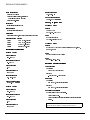
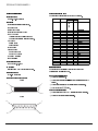
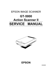
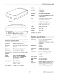
EPSON ACTIONSCANNER II Document cover Storage hole Parallel port Transportation screw DIP switch AC inlet Document glass (platen) Carriage (at home position) Storage hole Transportation screw Terminator DIP switch AC inlet OPERATE button OPERATE light RESET button ERROR light READY light SCSI interface connectors Color byte sequence mode: Three-pass scanning (R, G, B) Color line sequence mode: One-pass scanning (R, G, B) Scanner Specifications Scanner type: Flatbed, color/monochrome Photoelectric device: CCD line sensor Size: 50% to 200% in 1% steps Effective pixels: 2550 dots by 3510 dots at 300 dpi, 100% Image data: 8 bits per pixel per color saved as 8 bits per pixel per color, maximum Maximum document size: 216 mm by 297 mm (8.5 inches by 11.7 inches) U.S. letter size or A4 Brightness: 7 levels Scanning resolution: 300 dpi Text Enhancement Technology: Enable/disable selectable Output resolution: 50 dpi to 1200 dpi in 1 dpi steps Halftoning process: Enable/disable selectable 3 halftoning modes (A, B, and C) 4 dither patterns (A, B, C, and D) for bi-level data or quad-level data (2 downloadable dither patterns) Color separation: By switching light sources (R, G, B) Reading sequence: Monochrome mode: One-pass scanning (Dropout color selectable from Red, Green, or Blue) Color page sequence mode: Three-pass scanning (R, G, B) Scanners Gamma correction: 2 for CRT display 3 for printer 1 for user-defined 10/95 ActionScanner II-1 EPSON ACTIONSCANNER II Color correction: 1 type for CRT display 3 types for printer output, available in color line sequence mode only 1 type for user-defined Interface: Bidirectional parallel or SCSI Light source: Noble gas fluorescent lamps Input frequency: 49.5 to 60.5 Hz Power consumption: Approx. 18W (self testing) Safety, EMI, and EMS 100120 V model Safety: UL1950 (+D3) CSA 22.2 No. 950 (+D3) Reliability: Main unit MCBF: 100,000 cycles of carriage movements EMI: FCC 15B Class B: USA CSA 108.8 Class B: CANADA Dimensions and weight: Width: Depth: Height: Weight: 297 mm (11.9 inches) 443 mm (17.7 inches) 87 mm (3.5 inches) about 5 kg (11.1 lb) 220240 V model Safety: EN60950 (TÜV) EN60950 Nordic Deviation (NEMKO, FIMKO, DEMKO, SEMKO) Electrical Specifications 100120 V model EMI: EN55022 (CISPR Pub 22) Class B Rated voltage: 100120 VAC EMS: IEC 801-2, 801-3, 801-4 Input voltage range: 90132 VAC Rated current: 0.5 A Environmental Conditions Temperature: Operation: 5°C to 35°C (40°F to 95°F) Storage: 20°C to 60°C (4°F to 140°F) Rated frequency: 50 to 60 Hz Input frequency: 49.5 to 60.5 Hz Humidity: Operation: 10% to 80%, without condensation Storage: 10% to 85%, without condensation Power consumption: Approx. 18 W (self test) 220240 V model Rated voltage: 220240 VAC Operating conditions: Ordinary office or home conditions. Avoid extreme dust. Avoid operation under direct sunlight or near a strong light source. Input voltage range: 198264 VAC Rated current: 0.3 A Rated frequency: 50 to 60 Hz ActionScanner II-2 Note: Specifications are subject to change without notice. 10/95 Scanners EPSON ACTIONSCANNER II Signal pin assignments Parallel Interface Specifications Interface type: Bidirectional parallel Pin Return No. Pin Signal Direction Function 1 19 STROBE IN STROBE pulse to read in or send out data. Pulse width must be more than Data format: 0.5 microseconds at the receiving 8-bit parallel terminal. Synchronization: By external strobe pulse Handshaking: By ACKNLG and BUSY signals Logic level: Input/output data and interface control signals are TTL-level compatible 2 20 DATA0 IN/OUT These signals represent information 3 21 DATA1 IN/OUT of bits 1 to 8 respectively. Each 4 22 DATA2 IN/OUT signal is at a high level when data is 5 23 DATA3 IN/OUT logical 1 and low when it is logical 0. 6 24 DATA4 IN/OUT 7 25 DATA5 IN/OUT 8 26 DATA6 IN/OUT 9 27 DATA7 IN/OUT 10 28 ACKNLG OUT About a 12-microsecond pulse. Low indicates that data has been received and that the scanner is ready to accept more data. Connector type: 36-pin Centronics® type connector Connector pin arrangement: 11 29 BUSY OUT When this signal is high, the scanner cannot receive or send data. The signal is high: 1) during data entry 2) when the scanner is not ready 1 18 3) when the scanner has an error 19 36 12− 15 NC Not used 16 GND Logical ground level 17 C-GND Scanner chassis ground Timing Charts 18 NC Not used The figures below show the timing for the bidirectional parallel interface as viewed from the scanner. 19− 30 GND Twisted-pair return signal ground level 31 INIT IN When this signal level becomes low, the scanner is reset to the state OUT (from scanner to computer) when power is turned on. This level is usually High. The pulse width STROBE (O) must be more than 50 microseconds at the receiving BUSY (I) terminal. min 250 ns ACKNLG (I) min 0.5 us I DATA (I) DIR (O) (output) 32 NC 33 GND Not used Twisted-pair return signal ground level IN (from computer to scanner) 34− 35 NC Not used 36 DIR IN Low indicates the direction is input min 0.5 Ius STROBE (O) Return Pin denotes the twisted-pair return, to be connected at signal ground level. typ 5 us I BUSY (I) ACKNLG (I) For interface wiring, be sure to use a twisted-pair cable for each signal, and to complete the connection on the return side. These cables should be shielded and the min 0.5 us I ground connected to the chassis of the host computer and the scanner. DATA (I) min 0.5 us I DIR (O) Scanners min 0.5 Ius All interface conditions are based on TTL level. (output) min 0.5 Ius 10/95 ActionScanner II-3 EPSON ACTIONSCANNER II Signal pin assignments SCSI Specifications The direction of signals is as viewed from the scanner. Interface type: ANSI X3.131-1986 standard Signal Function: GND The following functions are included. BUS FREE phase ARBITRATION phase SELECTION/RESELECTION phase COMMAND phase (Logical Unit Number is fixed to 0 and command link function is not supported.) DATA phase Data in phase Data out phase STATUS phase MESSAGE phase MESSAGE IN phase MESSAGE OUT phase ATTENTION condition RESET condition I/O Pin No. 25 pin 1− 12 7,9 14−25 35−37 39−40 42 Electrical standard: As per ANSI X3.131-1986 Description 50 pin Ground 14 16 18 24 NC 13 Not connected DB0 I/O 26 8 Data bus 0 DB1 I/O 27 21 Data bus 1 DB2 I/O 28 22 Data bus 2 DB3 I/O 29 10 Data bus 3 DB4 I/O 30 23 Data bus 4 DB5 I/O 31 11 Data bus 5 DB6 I/O 32 12 Data bus 6 DB7 I/O 33 13 Data bus 7 DBP I/O 34 20 Data bus parity TERMPWR 38 25 Termination power ATN I 41 17 Attention BSY I/O 43 6 Busy ACK I 44 5 Acknowledge RST I 45 4 Reset MSG O 46 2 Message SEL I/O 47 19 Select C/D O 48 15 Control/Data REQ O 49 1 Request I/O O 50 3 Input/Output ID Setting: Initialization Connector type: The scanner can be initialized (returned to a fixed set of conditions) in the following ways. Selectable from 0 to 7 with the rotary switch. 25/50-pin connectors Hardware initialization: ❏ Connector pin arrangement: 50 pin ❏ When the power is turned on. When the scanner receives an INIT signal at the parallel interface (pin 31 goes low). 1 25 ❏ When the scanner receives a SCSI Reset signal at the SCSI interface. ❏ When you push the RESET button. Software initialization: 26 50 25 pin 13 25 ActionScanner II-4 ❏ When the software command ESC @ (initialize the scanner) is received. ❏ When the SCSI Bus Device Message is received. 1 14 10/95 Scanners EPSON ACTIONSCANNER II When this error occurs, try to rescan the document. The scanner returns to normal when it receives correct commands. Normally you do not need to reset the scanner. Lights and Buttons The scanner has three indicator lights and two buttons. Interface Error E RR O R l ig h t O PE RA TE b u t to n The interface setup is wrong, or the scanner is not properly connected to the computer. When this error occurs, check the interface connection. Then push the RESET button or turn the scanner off and then back on to reset it. Fatal Error RE SE T b u t to n R EA DY l i g h t This indicates one of the following problems: O PE RA T E li g h t OPERATE light (green) Comes on when the scanner is turned on. READY light (green) Comes on when the scanner is ready to scan images. This light flickers during scanning. When an error occurs, this light and the ERROR light indicate the type of error. ERROR light (red) Indicates when an error occurs. Along with the READY light, it indicates the type of error. OPERATE button Turns the scanner on and off. RESET button Resets the scanner after an error occurs. Pressing this button during scanning stops the scanner and may cause an error in the scanning software. Scanner Errors If an error occurs, the scanner stops operating and the READY and ERROR lights show the type of error. Error type READY ERROR Command error On On Interface error Off Flashing Fatal error Flashing Flashing One or more fluorescent lamps needs to be replaced. ❏ The transportation screw has not been removed. ❏ The scanner is broken. Check that the transportation screw has been removed; then push the RESET button. If the scanner still does not operate properly, try turning the scanner off, wait 10 seconds, and then turn it back on. If the scanner still does not operate properly, or if this error occurs repeatedly, consult your dealer. Cleaning the Scanner To keep the scanner operating at its best, clean it periodically. Before cleaning, unplug the power cable. Clean the outer case with mild detergent dissolved in water. If the document glass gets dirty, clean it with a soft dry cloth. If the glass is stained with grease or other hard-to-remove material, use a small amount of glass cleaner on a soft cloth to remove it. Wipe off any remaining liquid with a dry cloth. Be sure there is no dust on the document glass. Dust can cause white spots in the scanned image. Caution: Do not scratch or damage the document glass, and do not use a hard or abrasive brush to clean it. A damaged glass surface can decrease the scanning quality. Never use alcohol, thinner, or corrosive solvent to clean the scanner. These chemicals can damage the scanner components as well as the case. Command Error The scanner has received incorrect commands from the scanning software. Scanners ❏ 10/95 ActionScanner II-5 EPSON ACTIONSCANNER II Be careful not to spill liquid into the scanner mechanism or electronic components. This could permanently damage the mechanism and circuitry. Do not spray lubricants inside the scanner. Never open the scanner case. Replacing the Fluorescent Lamps The luminosity of the fluorescent lamps declines over time. If the lamps break or become too dim to operate normally, the scanner stops working and both the READY light and the ERROR light flash. When this happens, the lamp assembly must be replaced. For details, contact your dealer. Caution: Users should never open the scanner case. Information Reference List Engineering Change Notices None Product Support Bulletins None Related Documentation TM-ACTSCANII PL-ACTSCANII 4004518 CPD-3142 CPD-3143 ActionScanner II-6 ActionScanner II Service Manual ActionScanner II Parts Price List ActionScanner II Users Guide ActionScanner II Getting Started (for the PC) ActionScanner II Getting Started (for the Mac) 10/95 Scanners