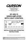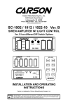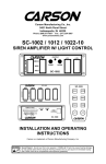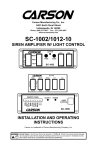
1
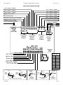
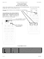
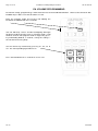
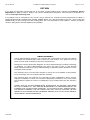
Carson Manufacturing Co., Inc.
5451 North Rural Street
Indianapolis, IN 46220
Phone: (888) 577-6877 Fax: (317) 254-2667
www.carsonsirens.com
CARSON
RAD
DIM
1 2 3
PHSR
WAIL
HORN
CYCL
YELP
MAN
S1
S2
S3
S4
S5
S6
S C - 41 1
SC-411HS-20 14
REMOTE SIREN
AMPLIFIER
WITH LIGHT
CONTROL
INSTALLATION AND
OPERATING
INSTRUCTIONS
Elite Force
With QuickClone®
WARNING: WEAR HEARING PROTECTION REF. OSHA 1910.95
Carson is a trademark of Carson Manufacturing Company, Inc.
Sound Hazard - Sound level from siren speaker (>120dBA @ 10 feet) may cause hearing damage.
Do not operate siren without adequate hearing protection for you and anyone in immediate vicinity.
(Ref. OSHA 1910.95 for occupational noise exposure guidelines)
Page 2 of 16
Installation and Operating Instructions
SC-411HS-20
TABLE OF CONTENTS
GENERAL DESCRIPTION ..................................................................................................................................... 3
SPECIFICATIONS .................................................................................................................................................. 3
INSTALLATION ....................................................................................................................................................... 4
SAFETY PRECAUTIONS................................................................................................................................... 4
UNPACKING ...................................................................................................................................................... 4
MOUNTING - Handheld Controller..................................................................................................................... 4
MOUNTING - Amplifier....................................................................................................................................... 4
ELECTRICAL CONNECTIONS - Amplifier ........................................................................................................ 4
OPTIONAL CONNECTIONS - Amplifier ............................................................................................................ 4
AMPLIFIER WIRING DIAGRAM ........................................................................................................................ 5
OPTION SETTINGS................................................................................................................................................ 6
Enter/Exit Program Mode, Reset........................................................................................................................ 6
S1 - S6 Button Operation ................................................................................................................................... 7
Primary Button / S1 - S6 Switch Linkage ........................................................................................................... 7
Option Set 1 (Input polarity, timed override, sweep/intersection, auto siren) .................................................... 8
Option Set 2 (Tone enables, short manual, primary progression) ..................................................................... 8
Option Set 3 (Alert, siren/lever video, center only, instant on)........................................................................... 9
PA Volume Programming ................................................................................................................................. 10
OPERATION ......................................................................................................................................................... 11
POWER ON/OFF.............................................................................................................................................. 11
SIREN CONTROLS.......................................................................................................................................... 11
Siren Mode.................................................................................................................................................. 11
Manual Button ............................................................................................................................................. 12
Horn Button ................................................................................................................................................. 12
PA ............................................................................................................................................................... 12
SIRCTRL Input (Optional)........................................................................................................................... 12
LITCTRL Input (Optional) ........................................................................................................................... 12
CUTOUT Input (Optional) ........................................................................................................................... 12
Timed Override (Optional) ......................................................................................................................... 12
Sweep/Intersection Function (Optional) .................................................................................................... 12
LIGHT SYSTEM CONTROLS .......................................................................................................................... 13
Primary Buttons .......................................................................................................................................... 13
Automatic Siren........................................................................................................................................... 13
Auxiliary Control Buttons ............................................................................................................................ 13
Arrow Stick Control Buttons........................................................................................................................ 13
Button Legends........................................................................................................................................... 13
DIM.............................................................................................................................................................. 13
Video Trigger Output .................................................................................................................................. 13
Alert ............................................................................................................................................................. 13
DIAGNOSTICS ................................................................................................................................................. 13
PROGRAM TRANSFER................................................................................................................................... 13
SERVICE............................................................................................................................................................... 14
PROBLEMS........................................................................................................................................................... 14
PARTS................................................................................................................................................................... 14
RETURN................................................................................................................................................................ 15
LIMITED WARRANTY........................................................................................................................................... 15
INSTALLATION CONFIGURATION RECORD .................................................................................................... 16
NOTICE
This Carson siren is intended for use by authorized personnel only. It is the user’s responsibility to ensure they understand and
operate this emergency warning device in compliance with all applicable city, state and federal laws and regulations.
Due to continuous product improvements, we must reserve the right to change any specifications and information, contained in this
manual at any time without notice.
Carson Manufacturing Co., Inc. makes no warranty of any kind with regard to this manual, including, but not limited to, the implied
warranties of merchantability and fitness for a particular purpose.
Carson Manufacturing Co., Inc. shall not be liable for errors contained herein or for incidental or consequential damages in connection with the furnishing, performance, or use of this manual.
4/1/14
CP5122A
SC-411HS-20
Installation and Operating Instructions
Page 3 of 16
GENERAL DESCRIPTION
The SC-411HS Remote Light Control/Siren is a premium unit designed for one or two 100W speaker use. The
primary operating modes are Radio, Cycler, Standby, Yelp, Wail, and Phaser. A Noise Canceling PA Override
and push-button Horn Override are available in all modes except Radio. A push-button is provided for toggling
between Wail, Yelp, and Phaser tones, and Manual siren control in silent modes. The Phaser tone can be
optionally replaced by Two-Tone or disabled entirely. Auxiliary inputs are provided for connection to horn ring
circuit or switch. A latching siren cutout input is provided for connection to a door switch, etc. to stop siren tones
when exiting the vehicle. PA volume is programmable on the handheld controller while Radio volume control is
on the amplifier. The front panel is backlit with LED's for night visibility, dimmable with a front panel button and/
or connection to dash lights. The siren circuits utilize short circuit, high voltage, and reverse polarity protection
for maximum service life. An indicator light on face is provided for siren output diagnostics.
The SC-411HS also provides 3 primary buttons (equivalent to lever switch operation) with LED indicators for
primary lighting system control of up to 50 amps total and automatic siren tone in last position. Six programmable lighted push buttons with replaceable legends provide auxiliary lighting or other device control up to 10
amps per switch. Each output is fused and monitored with visual and audible indicators for diagnostics. An
alert periodically sounds (may be disabled) when outputs are on to help prevent leaving lights on unintentionally. A video camera trigger output is activated with the primary buttons or programmed auxiliary buttons. Two
buttons are dedicated to arrow stick control (left, right, center) with function indication and specific control outputs.
All optional settings are programmed from the handheld controller face. These settings are synchronized between the handheld controller and amplifier using our QuickClone® duplication technology, a quick-copy feature
for simple transfer of option setting among multiple handheld controllers and amplifiers for efficient fleet installations.
Siren Section
Input Voltage
Input Current
10 - 16 VDC (negative ground)
16 AMPS (@14 VDC - two 100W speakers
Standby / Off Current
Audio Frequency
Audio Distortion
Audio Output
Less than 300 ma / less than 20 ma
200Hz - 10 kHz + 3db
Less than 7% @1 kHz - two 100W speakers
80 watts (@14 VDC - two 100W speakers
Audio Input
Output Power
Siren Frequency
Tones /
Cycle Rates
400 ohms + 10%
210 WATTS RMS MAX. (15 VDC - two 100W speakers)
700Hz - 1500Hz (Two-Tone and Horn = 435 & 585Hz)
Horn
Wail
Yelp
109 CPS
13 CPM
190 CPM
High Voltage Protection
Short Circuit Current
Operating Temp.
Controls
16 - 18 VDC will cause siren output to cease, resume at normal voltage
50 AMPS (supply circuit must be capable of supplying this)
-15° F to +140°F
5 - siren mode buttons (Radio, Cycler, Yelp, Wail, and Phaser).
Momentary push-button Horn button.
Momentary push-button Manual/Tone toggle button.
Momentary push-button Dimming button.
Enable input (positive) to turn on unit.
Auxiliary siren input programmable for positive or negative operation.
Auxiliary light control input programmable for positive or negative operation.
Cutout input programmable for positive or negative latching operation.
Face-programmable option settings.
(2) Neg, (2) Spkr, (2) Radio, Power, Siren Ctrl, Light Ctrl, Cutout, Backlit (#28-#12 AWG)
Connections (Rem. 12-Term Blk)
Phaser
15 CPS
Two-Tone
60 CPM
Light Control Section
Controls
Current (Primary outputs)
3 - primary buttons with button 3 siren activation and LED indicators
8 - on/off lighted push-buttons with replaceable legends
20 AMPS per circuit, 50 AMPS total
Current (Aux. outputs)
Connections
(Removable 3-Term Block)
(Removable 10-Term Block)
10 AMPS per switch, 30 AMPS total
Power Input - (2) screw terminal inputs (#22 to #6 AWG) 50A max each, external fuse reqd.
Primary Button outputs - (3) outputs (#22 to #10 AWG), 20A max each
Aux. Button outputs - (6) outputs (#22 to #12 AWG), 10A max each
Left, right & center arrow stick control outputs (#22 to #12 AWG), 0.2A max each
Video control output (#22 to #12 AWG), 0.2A max
General
Controller/Amplifier Interconnect
CAT 5e cable - 10ft coiled + 25ft extension (supplied)
Handheld Controller Mounting
Surface - Velcro® and custom magnetic cradle supplied
Size
Shipping Weight
Handheld Controller : 2-1/4” X 5-3/8” X 1-1/8”
6 LBS.
CP5122A
Amplifier: 8-3/4" X 8-1/4" X 2-1/8"
4/1/14
Page 4 of 16
Installation and Operating Instructions
SC-411HS-20
SPECIFICATIONS
INSTALLATION
Proper installation of the unit is essential for years of safe, reliable operation. Please read all instruction before
installing the unit. Failure to follow these instructions can cause serious damage to the unit or vehicle and may
void warranties.
SAFETY PRECAUTIONS
For the safety of the installer, vehicle operator, passengers and the community please observe the following
safety precautions. Failure to follow all safety precautions and instructions may result in property damage, injury or death.
Qualifications - The installer must have a firm knowledge of basic electricity, vehicle electrical systems and
emergency equipment.
Mounting - Mount the control handle for easy access by the vehicle operator. DO NOT mount in air bag deployment area. Assure clearances before drilling in vehicle. Mount the amplifier in a protected area with at
least 1” clearance on all sides for heat dissipation.
Wiring - Use wiring capable of handling the current required. Make sure all connections are tight. Route wiring
to prevent wear, overheating and interference with air bag deployment. Install and check all wiring before connection to vehicle battery.
Testing - Test all siren functions after installation to assure proper operation. Test vehicle operation to assure
no damage to vehicle.
Sound Hazard - Sound level from siren speaker (>120dBA @ 10 feet) may cause hearing damage.
Do not operate siren without adequate hearing protection for you and anyone in immediate vicinity.
(Ref. OSHA 1910.95 for occupational noise exposure guidelines)
Keep These Instructions - Keep these instructions in the vehicle or other safe place for future reference.
Advise the vehicle operator of the location.
UNPACKING
Inspect contents for shipping damage. If found alert carrier immediately. Contents should include handheld
controller, amplifier, Velcro mounting strips, legend sheet, (4) connectors, 25ft CAT 5e interconnect cable and
these instructions. Contact supplier immediately if any components are missing.
MOUNTING - Handheld Controller (if required)
The handheld controller can be surface mounted using the supplied Velcro® strips. A custom magnetic cradle
is supplied for more durable mounting (inspect behind mounting area for clearance).
Choose a mounting location convenient to the operator and away from any air bag deployment areas. Consider
cable routing.
MOUNTING - Amplifier
Choose a mounting location that will assure at least 1” clearance on all sides with adequate ventilation to prevent overheating. Inspect behind mounting area for clearance. Consider wire routing and access to connections. Make all wiring connections prior to mounting.
ELECTRICAL CONNECTIONS - Amplifier
Electrical connections to the unit are made using removable terminal blocks and screw terminals. Labels on the
unit identifies each terminal function. A CAT-5e cable connects between the control handle and the amplifier. If
the unit needs service the plugs can be easily removed without unwiring. Connect all wires prior to applying
power to the unit and prior to final mounting. Attach leads by stripping 3/8", inserting into plug and clamp by
tightening screw. Make sure the screw is tight and the wire can't be pulled out. Failure to adequately tighten
the screw can result in improper operation or burning the connector and wire.
POWER Input - This is like a power switch for the entire unit. Connect to a positive circuit controlled by the
vehicle ignition switch, usually a terminal at the vehicle fuse panel.
OPTIONAL CONNECTIONS - Amplifier
SIRCTRL Input - This input allows activation by an external source of either the Horn or other function.
Settable for +12 (default) or ground activation.
LITCTRL Input - This input allows cycling by an external source through the lever switch positions. Settable for
+12 (default) or ground activation.
CUTOUT Input - The Cutout Input turns off any siren tone output when activated, and remains off until a control
is activated or changed. Settable for +12 (default) or ground activation.
RADIO Input - Connect to radio output terminals or its speaker. The Radio Volume control is on the amplifier
and is a one time setting depending on the radio connected.
VIDEO Output - A video camera trigger output is activated high (+12) with the lever switch or programmed
auxiliary switches. See OPTION SETTINGS section.
LFT-A, RGT-A, CTR-A Outputs - These 3 active high (+12) outputs are available for arrow stick control.
LFT-A, RGT-A AND CTR-A outputs are active when center selected.
4/1/14
CP5122A
SC-411HS-20
Installation and Operating Instructions
Page 5 of 16
AMPLIFIER WIRING DIAGRAM
Aux switch 3 output
Aux switch 4 output
Aux switch 2 output
Aux switch 5 output
Aux switch 1 output
Aux switch 6 output
Right arrow stick
Lever switch 1 output
Left arrow stick
Lever switch 2 output
Center arrow stick (if needed)
Lever switch 3 output
Video camera trigger
(2) 50A fused inputs
(customer supplied)
CAT-5e interface cable
50A brkr
50A brkr
3-Pin Block
10-Pin Terminal Block
L3
L1
0.2 A max
Control
Outputs
20 A max 50 A max
Lever
+12 V
Switch
Battery
Outputs
POS
Input
10 A max
Auxiliary
Switch
Outputs
L2
S6
S5
S4
S3
S2
S1
RGT-A
LFT-A
CTR-A
VIDEO
SERIAL
COM
(CAT-5e)
SPKR
SPKR
NC
CUTOUT
SIRCTRL
LITCTRL
BACKLIT
RADIO
RADIO
POWER
GND
GND
BATT NEG
(10 A / lead)
RADIO
VOL
12-Pin Terminal Block
Recommended
Wire Size
+
Ignition Aux
+
Radio Spkr
Dash lights
Momentary switch
(to +12 or GND)
(5 A / spkr)
Amps
Size
<1
#22
1-5
#18
5 - 10
#16
10 - 15
#14
15 - 25
#12
25 - 40
#10
40 - 60
#8
60 - 80
#6
Use next larger size
if longer than 10 ft.
+VDC
HORN
RING
SWITCH
SPLICE
SIRCTRL
HORN
RING
SWITCH
HORN
Added
SPDT
Switch
HORN
AUX
SIRCTRL
+VDC Switching examples
CP5122A
MOMENTARY
FOOT
SWITCH
+VDC
-VDC
switching
example
ADDED DOOR
SWITCH
+VDC
DOOR
SWITCH
SPLICE
DOME
LIGHT
CUT
+VDC Switching
example
CUT
-VDC
switching
example
4/1/14
Page 6 of 16
Installation and Operating Instructions
SC-411HS-20
OPTION SETTINGS
Enter/Exit Program Mode, Reset
Option setting (programming) is done from the face of the handheld controller. Unit must be turned on with
POWER input. Make sure that all buttons are off.
Enter the program mode by pressing and holding S1, S2 and DIM for
3 seconds
The unit will beep 3 times and the backlighting
will begin flashing to indicate that the unit is in
program mode. It will continue to flash until
program mode is stopped by pressing and
holding DIM for 3 seconds, saving the settings—the unit will emit a long beep.
DIM
Press and hold for 3 seconds
to reset to factory default.
DIM
S1
S2
Press for next step.
Press and hold for 3
seconds to exit.
Program Mode Sections
Press DIM
0↓
4/1/14
Display
+ + ,
or
Programming
or
S1-S6 Button Operation, Primary / S1-S6 Button Linkage
1↓
blinking
Option Set 1 (Input polarity, timed, swp/int, auto)
2↓
blinking
Option Set 2 (Tone enables, short manual, lever progression)
3 0
blinking
Option Set 3 (Alert, siren/lever video)
CP5122A
SC-411HS-20
Installation and Operating Instructions
Page 7 of 16
S1 - S6 Switch Operation
Primary buttons 1, 2 & 3 all lighted
1
2
3
Change each switch’s operation by momentarily pushing the button.
See the table below for button status definition.
1. Light ON - Push On / Push Off with video output trigger active
(default)
2. Light OFF - Push On / Push Off with video trigger output deactivated.
3. Light flashing continuously - Momentary.
S1
S2
S3
S4
4. Light flashing with double pulse - Timed Momentary (Gun Lock Timer)
for duration of 10 seconds.
5. Light flashing with triple pulse - Timed Momentary (Gun Lock Timer)
for duration of 20 seconds.
6. The options will cycle through and repeat with each push of the button.
S5
S6
Note: Timed Momentary (Gun Lock Timer) is not be available for Primary
Button linkage.
Primary Button / S1 - S6 Button Linkage
Primary buttons set to 1, 2 or 3 —> 1, 2 or 3 lit
1
Press the desired auxiliary switch to turn on or off the light, linking it to the
lever switch position.
NOTE: Timed Momentary (Gun Lock Timer) programmed switches cannot be used.
2
3
S1
S2
S3
S4
S5
S6
Press the DIM button momentarily to move into next section, or DIM for 3
seconds to save & exit.
CP5122A
4/1/14
Page 8 of 16
Installation and Operating Instructions
SC-411HS-20
Option Set 1
(Input polarity, timed override, sweep/intersection, auto siren)
Primary button 1 light blinking
1
Momentarily press button
S1 - S6 to change.
S1
S2
S3
CUTOUT
Polarity
SIRCTRL
Polarity
LITCTRL
Polarity
ON - Pos
Blink - Neg
OFF Disable
ON - Pos
ON - Pos
Blink - Neg Blink - Neg
OFF OFF Disable
Disable
S4
S5
S6
BUTTON
Timed
Sweep / Automatic
FUNCTION
Override Intersection Siren
OFF
ON
OFF
ON
ON
OFF
OPTIONS
(Top is
default)
S1 (CUTOUT Input), S2 (SIRCTRL Input), S3 (LITCTRL Input) - These
inputs are normally activated by a 12V input (ON). Press the button once
until it FLASHES to change to ground activation. Press the button again
for OFF to disable.
S4 (Timed Override) - While the siren mode in Wail, Yelp or Phaser,
momentarily pressing the Manual button will override the Wail, Yelp or
Phaser tone. With this option ON the unit automatically goes back to the
previous tone after 10 seconds.
CUTOUT
Polarity
SIRCTRL
Polarity
LITCTRL
Polarity
Timed
Override
Sweep/
Intersect
Automatic
Siren
S5 (Sweep/Intersection Function) - While the siren mode is in Wail, Yelp,
or Phaser, momentarily activating the siren control input (SIRCTRL) will
change the unit into sweep mode, where the tone automatically changes
every few seconds. Press again to triple the change rate (intersection
mode). Press again to go back, or press twice to cancel.
S6 (Automatic Siren) An Automatic Siren feature turns on the siren in the
Wail mode when Primary button 3 is on.
Press the DIM button momentarily to move into next section, or DIM for 3
seconds to save & exit.
Option Set 2
(Tone enables, short manual, primary progression)
S1
TWOTONE
S2
S3
PHASER
Short
Enable MANUAL
OFF ON Phaser
Phaser
ON OFF Two-Tone Disable
(Yelp)
S4
HORN
Enable
S5
Progressive
Primary
OFF ON - Horn
ON Normal
Enabled Progressive
Manual
OFF Primary
ON - Short Disabled Operation
Manual
OFF - NonProgressive
Operation
S6
BUTTON
NonProgressive FUNCTION
Override
OFF OPTIONS
Normal
(Top is
Progression default)
ON - NonProgressive
Override
S1 (Two-Tone Enable) - Two-Tone replaces Phaser tone when ON.
Primary button 2 light blinking
2
Momentarily press button
S1 - S6 to change.
S2 (Phaser Enable) - Phaser (or Two-Tone) is disabled and replaced with
Yelp when OFF.
S3 (Short Manual Enable) - The Manual siren tone will normally die out
and stop when the Manual button is released. Turning option ON forces
the Manual siren tone to stop immediately upon release.
S4 (Horn Enable) - Horn tone is disabled when turned OFF.
S5 (Progressive Primary) - As the Primary buttons are moved from off to
position 3 outputs 1 and 2 stay on. Turn this option OFF For isolated
operation, where each output is independent.
S6 (Non-Progressive Override) - With Progressive Primary option off,
turning this option ON will turn on all 3 outputs when Primary button 3 is
active. Otherwise there is no effect.
TWOTONE
PHASER
Enable
Short
MANUAL
HORN
Enable
Prog
Primary
Non-Prog
Override
Press the DIM button momentarily to move into next section, or DIM for 3
seconds to save & exit.
4/1/14
CP5122A
SC-411HS-20
Installation and Operating Instructions
Page 9 of 16
Option Set 3
(Alert, siren/lever video)
S1
S2
S3
S4
SWITCH
Alert
Primary/
Siren Video
Center
Only
Instant
On
FUNCTION
ON - Alert
Active
OFF Disable
ON - Lever/
Siren Video
OFF Disable
OFF
ON
OFF
ON
OPTIONS
(Top is
default)
Primary button 3 light blinking
3
Momentarily press button
S1 - S4 to change.
Alert
Center
Only
Primary/
Siren
Video
Instant
On
S1 (Alert Enable) - Alert provides a periodic “beep” at the control head to
remind that a light is on. Turn off to disable this feature.
S2 (PrimarySiren Video) - VIDEO output is normally on when a Primary
button and/or Siren is active. Press button to disable. (NOTE: this does
not control the VIDEO Output for S1 - S6. See S1 - S6 Operation)
S3 (Center Only) - Only CTR-A output is on when center arrow stick
selected.
S4 (Instant On) - Primary buttons operate even when ENABLE input is
off. Arrow stick buttons active when Primary button active.
Press the DIM button momentarily to move into next section, or DIM for 3
seconds to save & exit.
NOTE: These option settings can be easily transferred to another vehicle. See PROGRAM TRANSFER.
CP5122A
4/1/14
Page 10 of 16
Installation and Operating Instructions
SC-411HS-20
PA VOLUME PROGRAMMING
PA volume setting (programming) is done from the face of the handheld controller. Unit must be turned on with
POWER input. Make sure that all buttons are off.
Enter the program mode by pressing and holding the
PA button and DIM button for 3 seconds.
DIM
The unit will beep 3 times and the backlighting will begin
flashing to indicate that the unit is in program mode. It will
continue to flash until program mode is stopped by pressing and holding DIM for 3 seconds, saving the settings—
the unit will emit a long beep.
Set the volume by momentarily pressing S1, S2, S3 or
S4. The corresponding light will turn on.
Press the DIM button for 3 seconds to save & exit.
4/1/14
LO
Med
LO
Med
HI
HI
CP5122A
SC-411HS-20
Installation and Operating Instructions
Page 11 of 16
OPERATION
This unit is designed for easy operation under the stress associated with high-speed pursuit. Most siren functions are accessible with one simple motion. Certain operational features or controlled by option settings and/or
installation connections.
CARSON
PA - Press button on side
and speak into microphone.
RAD
1 2 3
RADIO - Press for radio rebroadcast mode.
SIREN MODE - Press any
of these 4 buttons for siren
tone control. Turn off for
Standby mode.
DIM
PHSR
WAIL
HORN
CYCL
YELP
MAN
S1
S2
S3
S4
S5
S6
S C - 41 1
ARROW STICK - Press to
control Arrow Stick outputs.
Both on for center.
DIM - Press to change backlight level.
PRIMARY BUTTONS Simulate lever/slide switch
lighting control.
HORN BUTTON - Press for
simulated airhorn override.
MANUAL BUTTON - Press
for manual tone control and
various tone overrides.
AUXILIARY BUTTONS Press to activate auxiliary
lighting or device outputs.
Elite Force
With QuickClone®
WARNING: WEAR HEARING PROTECTION REF. OSHA 1910.95
POWER ON/OFF
The unit is powered by the ignition switch.
SIREN CONTROLS
SIREN MODE - These buttons select the primary operating mode of the siren.
CYCL - A standby mode dedicated for Horn Ring Cycler 2 (HRC2). During installation, the siren control input
must be connected to the horn ring or other switching device. Tap the horn ring to bring the unit out of standby
into Wail tone. Repeatedly tapping the horn ring will cycle through Wail, Yelp, and Phaser tones. Tapping the
horn ring twice quickly will stop the siren tones and return the unit to standby. Pressing and holding the horn
ring will produce Horn tone until released.
WAIL - A slower changing tone used on highways.
YELP - A rapidly changing tone used in congested areas.
PHSR - A very rapidly changing tone used at intersections or in highly congested areas. May be replaced with
Two-Tone (or Hi - Lo, a common European Tone) or disabled entirely.
RAD - Also known as Radio Repeat, this mode amplifies a radio speaker input for re-broadcast outside the
vehicle. A radio must be connected and the Radio Volume Adjusted. No siren tones or PA are available in this
mode.
STANDBY (All buttons off) - Turns off siren output, allowing Manual, Horn and Public Address operation.
CP5122A
4/1/14
Page 12 of 16
Installation and Operating Instructions
SC-411HS-20
OPERATION
(Continued)
MANUAL Button - Provides manual control of siren tone rise and fall while in Cycler or Standby. The falling
tone may be stopped immediately by setting the Short Manual option. With siren modes WAIL, YELP, or PHSR
this button toggles between tones.
HORN Button - Produces a simulated Air-Horn tone while pressed. Overrides all siren tones except Radio.
Horn tone may be disabled.
PA - The noise-canceling microphone is used for public address operation and overrides any siren tone when
the button on the side is pressed. Hold the microphone close to your lips for proper operation.
SIRCTRL Input (Optional) - During installation, the siren control input may be connected to the horn ring or
other switching device. Activation of this input will produce Horn tone or other functions depending on the Siren
mode as shown in the table below.
Siren Normal
Horn
Manual
Siren Control Input
Mode
Tone
Push-Button
Push-Button
(Horn Ring)
Radio
Radio Radio (No Effect) Radio (No Effect)
Radio (No Effect)
Cycler
Silent Momentary Horn
Manual Siren
HRC2
Standby Silent Momentary Horn
Manual Siren
Momentary Horn
Wail
Wail
Momentary Horn Wail/Yelp Toggle Mom. Horn (Opt. SWP/INT)
Yelp
Yelp
Momentary Horn Yelp/Phaser Toggle Mom. Horn (Opt. SWP/INT)
Phaser Phaser Momentary Horn Yelp/Phaser Toggle Mom. Horn (Opt. SWP/INT)
LITCTRL Input (Optional) - During installation, the light control input may be connected to a momentary switch.
Activation of this input will cycle through the Primary button positions, with the Pirmary button overriding if
moved.
CUTOUT Input (Optional) - During Installation, the cutout input may be connected to the vehicle door switch or
other switching device. Activation of this input will turn off any siren tone and remains off when deactivated until
a siren mode is changed.
Timed Override (Optional) - With Siren mode in Wail, Yelp, or Phaser, momentarily pressing the Manual pushbutton will toggle between tones overriding the Wail, Yelp, or Phaser tone. With this option selected the unit
automatically goes back to the Wail, Yelp, or Phaser tone after 10 seconds.
Sweep/Intersection Function (Optional) - The Sweep function is an automatic sequence of Yelp, Phaser, and
Horn tones allowing hands free operation. The Intersection function is a more rapid automatic sequence of
Yelp, Phaser, and Horn tones allowing hands free operation through intersections.
With Siren mode in WAIL, YELP, or PHSR, tap the horn ring to start Sweep function. Tap the horn ring again to
start the faster Intersection function. Repeatedly tapping the horn ring will switch between Sweep and Intersection functions. Tapping the horn ring twice quickly will return to Wail, Yelp, or Phaser tone. Pressing and holding the horn ring will produce Horn tone until released. Then the siren will return to the Sweep or Intersection
sequence.
4/1/14
CP5122A
SC-411HS-20
Installation and Operating Instructions
Page 13 of 16
OPERATION
(Continued)
LIGHT SYSTEM CONTROLS
3 Primary buttons control the primary lighting functions. Six additional programmable buttons are provided for
auxiliary lighting or other device control. Two dedicated buttons operate directional control lights (“Arrow Stick”).
An optional Instant On feature allows use of the Primary buttons with the ignition off.
Primary Buttons - These buttons by default provide progressive (additive) control of lighting functions. The
third button also provides Automatic Siren. The installer can change to non-progressive operation.
Automatic Siren - Primary button 3 provides Automatic Siren control. If the siren mode is set where there is no
siren tone output, the Automatic Siren will override with Wail or other tone. The cutout input will stop the siren
tone. This feature may be disabled.
Auxiliary Control Buttons - Six lighted pushbuttons are provided for various other lighting functions or device
control. The button lights Red when activated. The buttons may also be programmed for different functions,
and these buttons may be combined with each Primary button to automatically turn on and off.
Arrow Stick Control Buttons - Two dedicated buttons are provided to control traffic director lights on the vehicle. Press left or right buttons to set the direction. Turning on both will set the output to left, right and center.
These buttons can be used if any Primary button is active with the Instant On feature turned on.
Switch Legends - Different legends may be selected to match the device controlled. A sheet of labels is supplied.
DIM - The backlighting and indicator lights can be dimmed or turned off by repeatedly pressing the DIM button.
An optional connection to the vehicle dash lights may also control this level. This button will light whenever a
siren tone is produced.
Video Trigger Output - A video camera trigger output is activated with Primary buttons 1, 2, or 3 active. Programmed auxiliary control switches may also activate the output.
Alert - While the Primary buttons or auxiliary control buttons are on, an alert beep is sounded every 15 seconds.
This can be optionally disable.
DIAGNOSTICS
The unit monitors all outputs for faults, which are usually traced to shorted circuits. The unit indicates these
faults by flashing one or more lights and beeping. The following table shows fault indications and likely causes.
Control
Fault Indication
Likely Cause
Primary Button 1, 2 or 3
1, 2 or 3 flashes
Blown fuse at L1, L2 or L3
Button S1 - Button S6
Button flashes
Blown fuse at S1 - S6
Arrow Stick Button
Siren output
Button flashes
DIM flashes
LFT-A, RGT-A or CTR-A output shorted (auto-reset)
Blown siren fuse
PROGRAM TRANSFER (QuickClone®)
To facilitate programming of multiple vehicles this unit automatically synchronizes option settings between the
handheld controller and amplifier on power-up as shown. Transfer the settings to multiple vehicles by temporarily installing with a common handheld controller, power-up/down (transferring options to the amplifier), then
permanently install the supplied handheld controller. On power-up the options are transferred from the amplifier
to the handheld controller.
Option Settings
Action
Controller = Amp
Normal power-up
Controller not Default and Amp not Default
Controller settings transferred to Amp, power-up
Amp is Default and Controller not Default
Controller settings transferred to Amp, power-up
Amp not Default and Controller is Default
Amp settings transferred to Controller , power-up
If a handheld controller or amplifier is sent in for service it will be set to default prior to return, and will automatically synchronize with the mating part on power-up.
CP5122A
4/1/14
Page 14 of 16
Installation and Operating Instructions
SC-411HS-20
SERVICE
This unit is designed to provide years of reliable service under even the worst conditions. Many times there
may appear to be a problem with the unit when the true problem is in the speaker(s), controlled devices, or
improper installation. The following chart shows typical symptoms and possible causes.
A blown siren fuse doesn't necessarily mean that the unit is bad. If a speaker or speaker lead is shorted the
internal fuse will blow before the unit is damaged. Disconnect the speaker leads and replace the fuse. If the
DIM light comes on solidly with power on and Yelp selected it is OK. Check the speaker(s) or leads for possible
shorting.
PROBLEMS
Symptom
No power or siren
output
Possible Cause
Check
No power to POWER input
Bad speaker
Connector(s) loose
Amplifier fuse blown
Loose connection at power source
High Voltage Protection
Microphone button stuck
Cutout activated
Cutout Polarity set wrong
Speaker assembly loose
Intermittent SIRCTRL Input connection
Low vehicle voltage
High Voltage Protection
Connector loose
Bad power connection
Microphone button activation
Circuit breaker in supply connection
Does backlighting come on?
Do you hear a "pop" when turned on?
With siren on and Yelp selected, listen for tone in amplifier.
Is an external fuse or circuit breaker used?
Are the negative leads connected to a good ground?
Input voltage must be less than highest rated voltage.
Does microphone button release properly?
Does the siren work when CUTOUT input is disconnected?
Is the Cutout Input option properly configured?
Is the speaker bell or tip loose?
Is the SIRCTRL Input used and wired properly?
Input voltage must be greater than lowest rated voltage.
Is the vehicle voltage regulator working properly?
Is the connector tight on the back of the unit?
Is there a loose connection on a power lead?
Is something pressing the microphone button?
Are circuit breakers used with at least a 50A rating?
Horn function stuck
on or
Manual stuck on
No Radio
Horn or Manual button stuck
SIRCTRL Input improperly connected
SIRCTRL Input Polarity Option set wrong
Unit not connected to radio
Radio volume too low
Wrong siren tone
Two-Tone option installed
Aux Input set to wrong function
Tone disabled
Does the horn or manual button return when released?
Is the SIRCTRL Input used and wired properly?
Is the Siren Control option properly configured?
Is the radio connected properly to the unit?
Can you hear the radio in the vehicle?
Have you tried adjusting the radio volume control (amplifier)?
Is the Two-Tone option selected?
Is the Sweep/Intersection option selected?
Is Phaser/Two-Tone Enable option selected?
Is the Horn Enable option selected?
Is the Automatic Siren Enable option selected properly?
No siren tone - PA
works
Distorted siren
sound
Intermittent siren
tone
Phaser or Horn not
working
Automatic Siren not
working
Primary buttons not
working at all
Primary buttons not
working in some
positions
Aux control buttons
not working
Automatic Siren disabled
No power to lever switch
No ground at siren connector
Loose lever switch output connection
Do the Primary button indicators light?
Does the siren work?
Does the Primary button light in those positions?
Is the corresponding fuse blown?
No power to aux buttons
Loose aux switch output connection
Do the aux buttons light?
Is the corresponding fuse blown?
PARTS
The following parts are available from Carson Manufacturing Company, Inc.:
Part
CP5090-25-BK
Description
Cable, CAT5e 25ft Black
CP5128
CP4688-10
Connector, RJ45 Coupler
Connector, 10-Pin Removable Terminal Block
CP4688-12
Connector, 12-Pin Removable Terminal Block
CP5086-03
CP4990-150
Connector, 3-Pin Removable Terminal Block
Fuse, ATM 15 Amp Automotive Mini
CP4990-250
ED1952
CP4895
SC-411RS-20AMP
SC-411HX-20CH
Fuse, ATM 25 Amp Automotive Mini
Kit, SC-411 Handheld Cradle
Label, Aux Output Legends
SC-411 Single Tone Amplifier
SC-411 Handheld Controller
VELCRO
CP4119
CP5122
3” Mounting Strip
Transistor, Output (2 required) (Industry Standard TIP36C, must have metal tab)
Manual, SC-411HS-20 Installation and Operating
4/1/14
CP5122A
SC-411HS-20
Installation and Operating Instructions
Page 15 of 16
RETURN
If you have any questions concerning this or any other Carson product, please contact our Technical Service
Department at (888) 577-6877. Many issues can be handled over the phone. We can also be reached via email at [email protected]
If a product must be returned for any reason, please contact our Technical Service Department to obtain a
Returned Merchandise Authorization number (RMA#) before you ship the product to Carson. Please write the
RMA# clearly on the package near the mailing label. Be sure to provide a return address, contact and phone
number, along with a brief description of the problem.
LIMITED WARRANTY
Carson Manufacturing Company, Inc. warrants this new product to be free from defects
in material and workmanship, under normal use and service, for a period of five (5)
years from the date of delivery to the first user-purchaser.
During this warranty period the obligation of Carson Manufacturing is limited to repairing
or replacing, as Carson Manufacturing may elect, any part or parts of such product
which after examination by Carson Manufacturing is determined to be defective in material and/or workmanship.
This warranty does not cover labor charges for removal or re-installation of the product.
Fuses and lamps are not covered under this warranty.
This warranty does not extend to any unit that has been subjected to abuse, misuse,
improper installation or which has not been adequately maintained, nor to units which
have problems related to service or modification at any facility other than the manufacturer.
THERE ARE NO OTHER WARRANTIES, EXPRESSED OR IMPLIED, INCLUDING
BUT NOT LIMITED TO, ANY IMPLIED WARRANTIES OF MERCHANTABILITY OR
FITNESS FOR A PARTICULAR PURPOSE. IN NO EVENT SHALL CARSON MANUFACTURING COMPANY, INC. BE LIABLE FOR ANY LOSS OF PROFITS OR ANY
INDIRECT OR CONSEQUENTIAL DAMAGES ARISING OUT OF ANY SUCH DEFECT
IN MATERIALS OR WORKMANSHIP.
CP5122A
4/1/14
Page 16 of 16
Installation and Operating Instructions
SC-411HS-20
INSTALLATION CONFIGURATION RECORD
Terminal AWG Color Connected to
Terminal AWG Color Connected to
POS (2)
L1
GND (2)
L2
POWER
L3
RADIO (2)
S1
BACKLIT
S2
LITCTRL
S3
SIRCTRL
S4
CUTOUT
S5
SPKR
S6
SPKR
RGT-A
NC
X
X
X
LFT-A
VIDEO
CTR-A
S1—S6 Operation:
Blank=Default, V=No Video, M=Momentary, 10 or 20=Hold Time
Primary Button / S1 - S6 Switch Linkage: Blank=None, #=Pos
S1
S2
S3
S4
S5
S6
Operation
Association
Option Set 1
Option Set 3
Option
Default
Setting
Alert Enable
ON
ON OFF
Cutout Input
POS
POS NEG OFF
Primary/Siren Video
ON
ON OFF
Siren Control
POS
POS NEG OFF
Center Only
OFF
ON OFF
Instant On
OFF
ON OFF
Light Control
POS
POS NEG OFF
Timed Override
OFF
ON OFF
Sweep/Intersection
OFF
ON OFF
Vehicle ID
Automatic Siren
ON
ON OFF
Handheld Ctrl S/N
Option Set 2
Two-Tone
OFF
ON OFF
Phaser Enable
ON
ON OFF
Short Manual
OFF
ON OFF
Horn Enable
ON
ON OFF
Primary Progressive
ON
ON OFF
Non-Prog Override
OFF
ON OFF
Installed by:
4/1/14
General Information
Amplifier S/N
Notes:
Date:
CP5122A