1
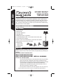
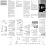
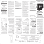
SC1000R I.S 325-1439
6/4/04
4:12 PM
Page 1
ENGLISH
Instruction Manual
Manual de Instrucciones
Directives
ESPAÑOL
1
FRANÇAIS
SC1000R 1000 Watt
Standlight with Cage
and Radio
ENGLISH
SC1000R I.S 325-1439
6/4/04
4:12 PM
Page 2
SC1000R 1000 WATT
STANDLIGHT WITH
CAGE AND RADIO
Congratulations! You have purchased a Regent 1000-watt stand light. This
versatile light is perfect for many different applications, which require either a
portable light fixture or a stand light. The built-in protective cage also serves as
a stand for the light fixture and a durable carrying case for transport and storage. The built-in radio allows you to listen to your favorite music while working
around the house or at the jobsite.
Required for Installation (Not Supplied)
• Phillips screwdriver
What’s included
• (2) Light fixtures
• Sled crossbar
• Protective cage/stand
• Adjustable pole
• AM/FM radio built into cage/stand
• (3) 500 Watt halogen bulbs – (one located in each fixture, plus
bonus bulb stored in handle)
• (8) M5 x 14mm round head machine screws with lock washers
(pre-installed in correct hole of the cage)
• Hardware bag
Upper bracket
Lower bracket
• (2) Wheels
What to know
NOTE: When using worklights, basic safety precautions should always be followed to reduce the risk of fire, electric shock, and personal injury including the
following:
IMPORTANT SAFETY INSTRUCTIONS
READ THESE INSTRUCTIONS:
KEEP THESE INSTRUCTIONS: HEED ALL WARNINGS
FOLLOW ALL INSTRUCTIONS
• Use only three wire extension cords that have three-prong grounding
plugs and grounding receptacles that accept the appliance’s plug.
• Ground Fault Circuit Interrupter (GFCI) protection should be provided
on the circuit(s) or outlet(s) to be used for the portable lamps.
Receptacles are available having built-in GFCI protection and are
able to be used for this measure of safety.
• Use only with an extension cord such as type S, S-A, SO, SO-A, ST,
Call for customer service and/or missing or damaged parts (800-334-6871)
2
SC1000R I.S 325-1439
6/4/04
4:12 PM
Page 3
SAVE THESE INSTRUCTIONS
INSTRUCTIONS PERTAINING TO A RISK OF FIRE, ELECTRIC
SHOCK, EXPOSURE TO EXCESSIVE UV RADIATION, OR
INJURY TO PERSONS
Lighted lamp is HOT!
To reduce the risk of FIRE, ELECTRIC SHOCK, EXPOSURE
TO EXCESSIVE UV RADIATION, OR INJURY TO PERSON:
• Do not block any ventillation openings. Install in accordance with the
manufacturer’s instructions.
• Unplug and allow to cool before replacing bulb.
• Bulb gets HOT quickly! Only contact switch/plug when turning on.
• Do not touch hot lens, guard, or enclosure.
• Do not remain in light if skin feels warm.
• Do not look directly at lighted bulb
• Keep bulb away from materials that may burn.
• Use only a 500 watt, or lower wattage halogen type “T” bulb. Use of
any other bulb will damage the fixture and void the warranty.
Installing a higher wattage bulb could create a fire hazard.
• Do not touch the bulb at any time. Use a soft cloth or gloves. Oil from
skin may damage bulb.
• Risk of exposure to excessive ultraviolet (UV) radiation. Do not operate unit with a missing or damaged guard, lamp containment barrier
or UV filter.
• Do not direct light at persons.
• Fixture must be connected to a 120 Volt, 60 Hz power source. Any
3
ENGLISH
ST-A, STO, STO-A, SJ, SJ-A, SJO, SJO-A, SJT-A, SJTO, OR
SJTO-A.
• This device complies with Part 15 of the FCC Rules. Operation is
subject to the following two conditions: (1) This device may not cause
harmful interference, and (2) this device must accept any interference
received, including interference that may cause undesired operation.
Under Part 15 of the FCC Rules, any changes or modifications to the
motion detector described in this instruction sheet that are not
expressly approved by Cooper Lighting could void the user’s authority to operate the equipment.
NOTE: This equipment has been tested and found to comply with the
limits for a Class B digital device, pursuant to part 15 of the FCC
Rules. These limits are designed to provide reasonable protection
against harmful interference in a residential installation. This equipment generates, uses and can radiate radio frequency energy and if
not installed and used in accordance with the instructions, may
cause harmful interference to radio communications. However, there
is no guarantee that interference will not occur in a particular
installation.
SC1000R I.S 325-1439
6/4/04
4:12 PM
Page 4
ENGLISH
other connection voids the warranty.
• The electrical system, and the method of electrically connecting the
fixture to it, must be in accordance with the National Electric Code
and local building codes.
• Do not use this apparatus near water.
• WARNING: Risk of electric shock. Do not use with extension cord
near water or where water may accumulate. Keep lamp at least 16
feet from pools and spas. Keep plugs and receptacles dry. For use
only on GFCI protected circuits.
• Disassembly of the fixture will void the warranty.
• If lens is replaced, use only tempered safety glass of equal thickness.
• For maximum bulb life, position light so that the halogen bulb
remains within 4° of horizontal.
• For dry location use.
• Clean only with dry cloth.
• Do not install near any heat sources such as radiators, heat registers, stoves, or other apparatus (including amplifiers) that produce
heat.
• Do not defeat the safety purpose of the polarized or grounding-type
plug. A polarized plug has two blades with one wider than the other
does. A grounding type plug has two blades and a third grounding
prong. The wide blade or the third prong is provided for your safety.
If the provided plug does not fit into your outlet, consult an electrician
for the replacement of the obsolete outlet.
• Protect the power cord from being walked on or pinched particularly
at plugs, convenience receptacles, and the point where they exit from
the apparatus.
• Only use attachments/accessories specified by the manufacturer.
• Unplug this apparatus during lightning storms or when unused for
long periods of time.
• Refer all servicing to qualified service personnel. Servicing is
required when the apparatus has been damaged in any way, such as
power-supply cord or plug is damaged, liquid has been spilled or
objects have fallen into the apparatus, the apparatus has been
exposed to rain or moisture, does not operate normally, or has been
dropped.
SAVE THESE INSTRUCTIONS
NOTE: Deviation from the assembly instructions may result in a risk of fire or
electric shock.
Assembling your fixture
Step 1:
Step 2:
Carefully remove the cage from box and place on floor in an upright
position. The bottom of the cage contains the legs and hinge assembly for the doors.
Release the light fixture from the cage door by carefully unlatching
4
SC1000R I.S 325-1439
Step 4:
Step 5:
Step 6:
Step 7:
Step 8:
4:12 PM
Page 5
the locking clamp on the center pole of the door (Figure A). This is
done by pulling up on the lock lever and disengaging the top hook
end. The portable unit will remain supported by the lower hook.
Open the door opposite the locking clamp. To open the
door, first release the spring loaded door locks by pulling
the lock knob towards the center of the door until the latch
pin clears the hole. Rotate the door until it stops with
FIG. A
the knee action locking bars fully extended.
Remove the portable light fixture by first raising the unit
off of the hook. Lower the portable fixture to the floor of the cage, and
lean the top of the unit towards the open door. Pull the portable fixture out of the cage and place it upright on the ground. Remove vertical pole and all other loose parts from the cage including all packing
material. Open the door on the other side of the cage
using the same procedure as in Step 3.
Remove all of the hardware from its packaging and check
the “What’s included” list in the owners manual to be sure
that all of the components are available for assembly.
Carefully lay cage on the front face so that the rear of the
FIG. B
cage in facing up, for pole bracket and wheel attachment.
Remove screws from the bracket mounting holes on the
back of the cage and attach bottom pole bracket and top
pole bracket to cage leaving the screws slightly loose.
(Figure B). (NOTE: Bottom pole bracket is the bracket with
one end closed to prevent tube from falling through.)
Remove screw from bottom of adjustable pole and slide
FIG. C
adjustable pole down through the two pole brackets and
align notch in tube with formed metal tab inside of the bottom bracket.
Attach pole to bottom bracket using the screw that was
removed (Figure C). Securely tighten all (4) bracket
mounting screws after bottom pole screw has been
secured.
Remove wheel mounting screws on back/side of the
cage and secure wheels in place using the screws
that were just removed (Figure D).
FIG. D
Pick up cage and set it in an upright position.
Use as a stand light
Step 1:
Release the light fixture from the cage door by carefully unlatching
the locking clamp on the center pole of the door. (Figure A) This is
done by pulling up on the lock lever and disengaging the top hook
end. The portable unit will remain supported by the lower hook. Open
the door opposite the locking clamp. To open the door, first release
the spring loaded door locks by pulling the lock knob towards the
center of the door until the latch pin clears the hole. Rotate the door
until it stops with the knee action locking bars fully extended. Remove
the portable light fixture by first raising the unit off of the hook. Lower
the portable fixture to the floor of the cage, and lean the top of the
unit towards the open door. Pull the portable fixture out of the cage
5
ENGLISH
Step 3:
6/4/04
ENGLISH
SC1000R I.S 325-1439
Step 2:
Step 3:
Step 4:
NOTE:
weight:
6/4/04
4:12 PM
Page 6
and place it upright on the ground. Loosen the wing nuts holding the
tab handles and raise the handles to an upright position. Open the door on the other side of the cage
using the same procedure as above. Stabilizing legs
on both doors must be lowered down to stabilize
and level cage/stand prior to attaching portable fix- FIG. A
ture to the pole. Lower the stabilizing legs by loosening the oval knobs and pulling down on the legs until
the desired length has been achieved. Lock legs in the desired position by tightening the oval knobs (Figure E).
Adjust the vertical pole to the desired height by loosening and tightening the collars on the pole (Figure F).
Lower the travel handle by pushing out and down on
the handle.
Lift center handle of fixture by loosening the knob on
the back of the handle’s vertical tube and raising the
FIG. E
handle. (Figure G) Tighten the knob to hold handle in
“up” position. NOTE: Handle must be in “up” position
before using handle to avoid contacting the housing
when carrying portable unit. Attach portable fixture to
the vertical pole by placing the Quick-ReleaseTM collar
over the top of the tube. Tighten the knob on the collar
until the screw is secure.
Plug light into a GFCI protected 120-volt receptacle. To
FIG. F
turn light ON, or OFF, push red switch on the back of
each fixture.
Cage must be secured with sand bags or other suitable
• When used on uneven or rocky surfaces
• When used in windy areas
• Anytime extra stability is required.
FIG. G
Use as a portable light
Step 1:
Step 2:
Release the light fixture from the cage door by carefully unlatching
the locking clamp on the center pole of the door. This is done by
pulling out on the lock lever and disengaging the top hook end. The
portable unit will remain supported by the lower hook. Open the door
opposite the locking clamp. To open the door, first release the spring
loaded door locks by pulling the lock knob towards the center of the
door until the latch pin clears the hole. Rotate the door until it stops
with the knee action locking bars fully extended. Remove the portable
light fixture by first raising the unit off of the hook. Lower the portable
fixture to the floor of the cage, and lean the top of the unit towards
the open door. Pull the portable fixture out of the cage. Loosen the
wing nuts holding the tab handles and raise the handles to an upright
position. Tighten the wing nuts.
Lift center handle of fixture by loosening the knob on the back of the
handle’s vertical tube and raising the handle. (Figure H) Tighten the
6
SC1000R I.S 325-1439
Step 4:
4:12 PM
Page 7
knob to hold handle in “up” position. NOTE: Handle must be in “up”
position before using handle to avoid contacting the
housing when carrying portable unit. Use the light fixtures by setting the built-in stand on any flat surface.
For maximum safety, portable light fixtures should
always be plugged into a GFCI (Ground Fault Circuit
FIG. H
Interrupter) protected, 120-volt circuit.
To turn light ON, or OFF, push red switch on the back of each fixture.
How to store after use
Step 1:
Step 2:
Step 3:
Step 4:
Step 5:
Step 6:
Make sure fixtures are cool. If used as a standlight, loosen the QuickReleaseTM knob and raise the portable fixture off of the pole using the
center handle.
Lower adjustable pole by loosening the upper locking collar and lowering the pole until it stops. Tighten the locking collar to secure it in
place. Repeat this step using the lower locking collar to lower the next
section of the adjustable pole.
Raise the stabilizing legs on both of the doors by loosening the knobs
on the door and pushing up on the leg until it is fully seated against
the bottom of the door. Retighten the knobs to hold them in place.
Push on the center joint of the knee action bracket on left door (door
with fixture hook) to allow door to start to close. Continue to rotate
door until almost closed. Pull out the latch knob until door is closed.
Release tension on the latch knob once pin is centered over the hole
in vertical tube of cage to lock door closed.
Lower the center handle of fixture by loosening the knob on the back
of the handle’s vertical tube. Tighten the knob to hold handle in the
“storage” position. Loosen the wing nuts holding the tab handles and
fold the handles to the side of the fixture. Tighten the wing nuts. Place
the portable unit in the cage stand legs first, starting with the lower
section of the portable unit. Once the lower section is in the cage and
resting on the bottom, lean the entire portable unit into the cage and
rest fixture on lower locking
bracket. Place the upper bracket arm over the end of the lower bracket and push down on the outer arm to lock fixture in place.
Push on the center joint of the knee action bracket on opposite door
to allow door to start to close. Continue to rotate door until almost
closed. Pull out the latch knob until door is closed. Release tension
on the latch knob once pin is centered over the hole in vertical tube
of cage to lock door closed.
To transport the cage to another location, raise and lock the travel handle
on the top vertical tube into position, grab the handle and lean the unit
back onto the wheels at the bottom of the cage to roll away.
7
ENGLISH
Step 3:
6/4/04
SC1000R I.S 325-1439
6/4/04
4:12 PM
Page 8
ENGLISH
Bonus bulb included
This fixture includes a spare bulb, which insures that you can
always finish your job or project without interruption due to bulb
failure. The spare bulb and holder are located in the center handle of the portable fixture (Figure I) NOTE: Always handle
halogen bulbs with gloves or with a clean soft cloth. Oil from your
skin can cause premature failure of the bulb.
FIG. I
Replacing the bulb
Step 1:
Step 2:
Step 3:
Step 4:
Step 5:
Make sure fixture is turned OFF and unplugged.
Turn wing nut on back of handle counterclockwise to remove handle.
Using a Phillips screwdriver loosen the screw on the front of the door.
The door frame and lens assembly will swing down
allowing access to the bulb.
Using gloves or soft cloth, press the old bulb to one side
of the spring loaded socket as indicated on the metal
reflector. Remove opposite end of bulb from the other
FIG. J
side of the socket. Remove the new bulb from its package
making sure not to touch bulb with bare hands. Reverse this procedure to install a new replacement bulb (Figure J).
Replace the door frame and lens assembly and secure it using a
phillips screwdriver.
Aiming the fixture
Make sure the light fixture is in the OFF position and cool. Loosen
the knob located on the side of the light fixture housing. Using the
tab handle on the light fixture, tilt to desired position then retighten
knobs (Figure K). There is a stop that restricts the downward and
inward movement of the fixture for safety reasons. To prevent overheating and risk of burns or fire, do not aim the fixture down at an
angle of more than 10 degrees from horizontal.
FIG. K
AM/FM Radio Operation
Electrical cord located on the back of the cage/stand must be plugged
into power source for radio to operate.
Allows external
LED light indicates Adjusts volume to
LED light indicates stereo reception
be louder by turning CD player to be
station reception
used with radio
knob to the right
Displays radio
station selected
Turns radio on/off
with press of button
98.5
Selects AM/FM LED light indicates Selects radio
radio stations
stereo/mono
station by turning
selection
knob left or right
Two year limited warranty
Cooper Lighting (“the Company”) warrants this product (“the product”) against
defects in material or workmanship for a period of two years from date of origi-
8
SC1000R I.S 325-1439
6/4/04
4:12 PM
Page 9
Customer First Center • 1121 Highway 74 South, Peachtree City, GA 30269 USA
Call for customer service and/or missing or damaged parts (800-334-6871)
www.cooperlighting.com
© 2004 Cooper Lighting
Reproductions of this document without prior written approval of Cooper Lighting are strictly prohibited.
Printed in China
9
ENGLISH
nal purchase, and agrees to repair or, at the Company’s option, replace a
defective product without charge for either replacement parts or labor during
such time. This does not include labor to remove or install fixtures.
This warranty is extended only to the original purchaser of the product. A purchaser’s receipt or other proof of date of original purchase acceptable to the
Company is required before warranty performance shall be rendered.
This warranty only covers product failure due to defects in materials or workmanship which occurs in normal use. It does not cover the bulb or failure of the
product caused by accident, misuse, abuse, lack of reasonable care, alteration,
faulty installation, subjecting the product to any but the specified electrical service or any other failure not resulting from defects in materials or workmanship.
Damage to the product caused by separately purchased, non Company brand
replacement bulbs and corrosion or discoloration of brass components are not
covered by this warranty.
There are no express warranties except as described above.
THE COMPANY SHALL NOT BE LIABLE FOR INCIDENTAL, SPECIAL OR
CONSEQUENTIAL DAMAGES RESULTING FROM THE USE OF THE PRODUCT OR ARISING OUT OF ANY BREACH OF THIS WARRANTY. ALL
IMPLIED WARRANTIES, IF ANY, INCLUDING IMPLIED WARRANTIES OF
MERCHANTABILITY AND FITNESS FOR A PARTICULAR PURPOSE, ARE
LIMITED IN DURATION TO THE DURATION OF THIS EXPRESS WARRANTY.
Some states do not allow the exclusion or limitation of incidental or consequential damages, or limitations on how long an implied warranty lasts, so the above
exclusions or limitations may not apply to you.
No other warranty, written or verbal, is authorized by the Company. This warranty gives you specific legal rights and you may also have other rights which
vary from state to state.
To obtain warranty service, please write to Cooper Lighting, 1121 Highway 74
South, Peachtree City, GA 30269. Enclose product model number and problems you are experiencing, along with your address and telephone number.
You will then be contacted with a solution, or a Return Goods Authorization
number and full instructions for returning the product. All returned products
must be accompanied by a Return Goods Authorization Number issued by the
Company and must be returned freight prepaid. Any product received without a Return Goods Authorization Number from the Company will be
refused.
Cooper Lighting is not responsible for merchandise damaged in transit.
Repaired or replaced products shall be subject to the terms of this warranty
and are inspected when packed. Evident or concealed damage that is made in
transit should be reported at once to the carrier making the delivery and a
claim filed with them.
SC1000R I.S 325-1439
6/4/04
4:12 PM
Page 10
SC1000R 1000
VATIOS LUZ DE PEDESTAL
CON JAULA Y RADIO
¡Felicitaciones! Usted ha comprado una lámpara de pedestal Regent de 1000
watts. Esta versátil lámpara es perfecta para muchas diferentes aplicaciones,
que requieren un porta-bombilla portátil o una lámpara de pedestal. La jaula
protectora incorporada también sirve como pedestal para el porta-bombilla, y
un durable estuche sirve para transporte y almacenamiento. El radio incorporado le permite escuchar su música favorita mientras trabaja alrededor de la
casa o en el lugar de trabajo.
Requerido para Instalación (No Suministrado)
• Atornillador Phillips
ESPAÑOL
Qué se incluye
• (2) porta-bombilla
• Travesaño de trineo
• Jaula protectora / pedestal
• Poste ajustable
• Radio AM/FM incorporada en la jaula/pedestal
• (3) bombillas halógenas de 500 Watts – [una (1) ubicada en
cada porta-bombilla, más bombilla adicional guardada en la
manija]
• (8) tornillos de cabeza redonda M5 x 14mm con arandelas de
seguridad (pre-instalados en el respectivo agujero de la jaula)
• Bolsa de herrajes
Soporte superior
Soporte inferior
• (2) Ruedas
Qué se debe saber
NOTA: Cuando las lámparas de trabajo se utilizan, siempre deben seguirse
precauciones de seguridad básicas para reducir el riesgo de incendio, choque
eléctrico, y lesiones personales, incluyendo lo siguiente:
Instrucciones Importantes de Seguridad
LEA TODAS LAS INSTRUCCIONES
CONSERVE ESTAS INSTRUCCIONES : PRESTE
ATENCIÓN A TODAS LAS ADVERTENCIAS
Siga Todas las Instrucciones
• Sólo utilice cables de extensión para exteriores de tres alambres con
enchufe de tres patas incluyendo la pata de conexión a tierra y
tomacorrientes con conexión a tierra que acepten el enchufe del
aparato.
Llame para solicitar servicio al cliente y/o piezas faltantes o dañadas (800-334-6871)
10
SC1000R I.S 325-1439
6/4/04
4:12 PM
Page 11
GUARDE ESTAS INSTRUCCIONES
INSTRUCCIONES RELACIONADAS CON RIESGO DE INCENDIO, CHOQUE ELÉCTRICO, EXPOSICIÓN A EXCESIVA
RADIACIÓN UV, ó LESIONES A PERSONAS.
¡La lámpara encendida está CALIENTE!
Para reducir el riesgo de INCENDIO, CHOQUE ELÉCTRICO,
EXPOSICIÓN A EXCESIVA RADIACIÓN UV, ó LESIONES A
PERSONAS:
• No bloquee ninguna abertura de ventilación. Instálelo de acuerdo
con las instrucciones del fabricante.
• Desenchufe y permita enfriar antes de reemplazar la bombilla.
• ¡La bombilla se CALIENTA rápidamente!. Sólo haga contacto con el
interruptor/ enchufe en el momento de encender la lámpara.
• No toque los lentes, protector, o cubierta calientes.
• No permanezca cerca de la lámpara si la piel siente calor.
• No mire directamente a la bombilla encendida.
• Mantenga alejada la bombilla de materiales que pudieran
incendiarse.
11
ESPAÑOL
• Debe suministrarse protección mediante Interruptor de Circuito por
Falla a Tierra (GFCI) en el circuito(s) o tomacorriente(s) que se utilizará para conectar las lámparas portátiles en sitios húmedos. Los
tomacorrientes están disponibles con protección por GFCI incorporado y pueden utilizarse para esta medida de seguridad.
• Sólo utilice con cables de extensión para uso en exteriores, tales
como los cables de extensión tipo S, S-A, SO, SO-A, ST, ST-A, STO,
STO-A, SJ, SJ-A, SJO, SJO-A, SJT-A, SJTO, ó SJTO-A.
• Este dispositivo cumple con la Parte 15 de las Reglas de la
Comisión Federal de Comunicaciones (FCC) de los E. U. de A. La
operación está sujeta a las dos condiciones siguientes: (1) Este dispositivo no puede causar interferencia dañina, y (2) este dispositivo
debe aceptar toda interferencia recibida, incluyendo la interferencia
que pueda causar un funcionamiento indeseado. Según la Parte 15
de las Reglas de la FCC, todo cambio o modificación al detector de
movimiento descripto en esta hoja de instrucciones que no esté
expresamente aprobado por Cooper Lighting, podría anular la autorización del usuario para operar el equipo.
NOTA: Este equipo ha sido probado, y se ha verificado que cumple
con los límites de un dispositivo digital Clase B, de acuerdo con la
parte 15 de las Reglas de la FCC. Estos límites están diseñados a
fin de proveer una protección razonable contra la interferencia dañina en una instalación residencial. Este equipo genera, usa y puede
irradiar energía de radio frecuencia, y si no se instala y utiliza de
acuerdo con las instrucciones, puede causar interferencia dañina en
las comunicaciones de radio. Sin embargo, no se garantiza que no
vaya a producirse interferencia en una instalación en particular.
ESPAÑOL
SC1000R I.S 325-1439
6/4/04
4:12 PM
Page 12
• Sólo utilice bombilla halógena tipo “T” de 500 watts o menos. El uso
de cualquier otra bombilla dañará el porta-bombilla y anulará la
garantía. La instalación de una bombilla de mayor vatiaje (watts)
podría crear un riesgo de incendio.
• No toque la bombilla en ningún momento. Utilice una tela suave o
guantes. La grasa de la piel podría dañar la bombilla.
• Riesgo de exposición a excesiva radiación ultravioleta (UV). No
opere la unidad sin un protector, barrera de contención de lámpara o
filtro de UV.
• No dirija la lámpara a las personas.
• El porta-bombilla debe conectarse a una fuente de energía de 120
Voltios, 60 Hz. Cualquier otra conexión anula la garantía.
• El sistema eléctrico, y el método de conexión eléctrica del portabombilla con este sistema eléctrico, deben estar de acuerdo con el
Código Eléctrico Nacional y los códigos de construcción locales.
• No utilice este aparato cerca del agua.
• ADVERTENCIA: Riesgo de choque eléctrico. No utilice con cable de
extensión cerca del agua o donde el agua pudiera acumularse.
Mantenga la lámpara a una distancia mínima de 16 pies de piscinas
y fuentes de agua. Mantenga secos los enchufes y tomacorrientes.
Para uso sólo en circuitos protegidos con Interruptor de Circuito por
Falla a Tierra.
• El desarme del porta-bombilla anulará la garantía.
• Si se reemplazan los lentes, sólo utilice vidrio de seguridad templado de igual espesor.
• Para lograr máxima vida de servicio de la bombilla, coloque la lámpara de manera que la bombilla halógena permanezca a 4° con
respecto a la horizontal.
• Apto para ubicaciones secas
• Límpielo únicamente con un paño seco
• No lo instale cerca de ninguna fuente de calor, como radiadores,
rejillas de aire caliente, estufas u otros aparatos (incluídos amplificadores) que produzcan calor.
• No anule el objetivo de seguridad del enchufe polarizado o con
puesta a tierra. Un enchufe polarizado tiene dos láminas, una más
ancha que la otra. Un enchufe con puesta a tierra tiene dos láminas,
y una tercera espiga para la puesta a tierra. La lámina ancha, o la
tercera espiga, se han provisto para su seguridad. Si el enchufe provisto no se adapta a su tomacorriente, consulte con un electricista
para el reemplazo del tomacorriente anticuado.
• Proteja el cordón de alimentación eléctrica para evitar que lo pisen o
lo estrujen, particularmente en su unión con enchufes y tomacorrientes, y en el punto en que sale del aparato.
• Utilice únicamente aditamentos y accesorios especificados por el
fabricante.
• Desenchufe este aparato durante tormentas eléctricas o cuando no
se lo vaya a utilizar por períodos de tiempo prolongados.
12
SC1000R I.S 325-1439
6/4/04
4:12 PM
Page 13
• Confíe todas las tareas de reparación a personal de servicio calificado. La reparación es necesaria si el aparato ha sido dañado de
cualquier modo, como por ejemplo si se ha dañado el cordón de alimentación eléctrica o el enchufe, si se ha derramado líquido o han
caído objetos dentro del aparato, o si el aparato ha sido expuesto a
la lluvia o a la humedad, no funciona normalmente o se ha caído.
GUARDE ESTAS INSTRUCCIONES
NOTA: No seguir estrictamente las instrucciones de ensamblaje podría resultar en un peligro de incendio o choque eléctrico.
Ensamblaje de su porta-bombilla
13
ESPAÑOL
Paso 1: Remueva cuidadosamente la jaula de la caja y colóquela sobre el
piso en posición vertical. El fondo de la jaula contiene las patas y el
conjunto de bisagra para las puertas.
Paso 2: Libere el porta-bombilla de la puerta de jaula removiendo
cuidadosamente el pasador de la abrazadera de sujeción
en la barra central de la puerta (Figura A). Esto se hace
halando la palanca de sujeción y desenganchando el
FIG. A
extremo del gancho superior. La unidad portátil permanecerá soportada por el gancho inferior.
Paso 3: Abra la puerta opuesta a la abrazadera de sujeción. Para abrir la
puerta, primero libere las cerraduras resortadas de puerta halando la
perilla de la cerradura hacia el centro de la puerta hasta que el
pasador de cierre despeje el agujero. Gire la puerta hasta que se
detenga con las barras de sujeción de acción articulada totalmente
extendidas.
Paso 4: Remueva el porta-bombilla portátil levantando primero la unidad
fuera del gancho. Baje el porta-bombilla portátil al piso de la jaula, e
incline la parte superior de la unidad hacia la puerta abierta. Saque
de la jaula el porta-bombilla portátil y colóquelo verticalmente sobre
el piso. Remueva el poste vertical y todas las otras piezas sueltas de
la jaula incluyendo todo el material de empaque. Abra la puerta
sobre el otro lado de la jaula utilizando el mismo procedimiento del
Paso 3.
Paso 5: Saque todos los herrajes de su empaque y verifique con la lista de
“Qué se incluye” incluida en el manual del propietario para asegurarse que todos los componentes están disponibles para ensamblaje.
Paso 6: Coloque cuidadosamente la jaula sobre la cara delantera
de manera que la parte trasera de la jaula quede dirigida
hacia arriba, para conexión del soporte de poste y las
ruedas. Remueva los tornillos de los agujeros de montaje del soporte ubicados en la parte trasera de la jaula y
fije el soporte inferior y el soporte superior del poste a la
FIG. B
jaula dejando los tornillos ligeramente flojos (Figura B).
(NOTA: El soporte inferior del poste es el soporte que tiene un
extremo cerrado para evitar que el tubo caiga a través). Remueva el
tornillo del fondo del poste ajustable y deslice hacia abajo el poste
SC1000R I.S 325-1439
6/4/04
4:12 PM
Page 14
ajustable a través de los dos soportes del poste y alinee
la ranura en el tubo con la lengüeta metálica conformada ubicada dentro del soporte inferior. Fije el poste al
soporte inferior utilizando el tornillo que se removió
(Figura C). Apriete firmemente todos los (4) tornillos de
montaje del soporte después de haber asegurado el
FIG. C
tornillo inferior del poste.
Paso 7: Retire los tornillos de montaje de las ruedas ubicados en
la parte trasera/ lateral de la jaula y asegure las ruedas
en su sitio utilizando los tornillos que se acaban de
retirar (Figura D).
Paso 8: Levante la jaula y colóquela en posición vertical con la
FIG. D
parte superior del poste dirigida hacia arriba.
ESPAÑOL
Uso como lámpara de pedestal
Paso 1: Libere el porta-bombilla de la puerta de jaula removiendo cuidadosamente el pasador de la abrazadera de sujeción en la barra central de
la puerta. Esto se hace halando la palanca de sujeción y desenganchando el extremo del gancho superior. La unidad portátil permanecerá soportada por el gancho inferior. Abra la puerta opuesta a
la abrazadera de sujeción. Para abrir la puerta, primero libere las
cerraduras resortadas de puerta halando la perilla de la cerradura
hacia el centro de la puerta hasta que el pasador de cierre despeje el
agujero. Gire la puerta hasta que se detenga con las barras de sujeción de acción articulada totalmente extendidas. Remueva el portabombilla portátil levantando primero la unidad fuera del gancho. Baje
el porta-bombilla portátil al piso de la jaula, e incline la parte superior
de la unidad hacia la puerta abierta. Saque de la jaula el porta-bombilla portátil y colóquelo verticalmente sobre el piso. Afloje las tuercas
tipo mariposa que sostienen las manijas tipo orejeta y levante las
manijas a una posición vertical. Abra la puerta del otro lado de la
jaula utilizando el mismo procedimiento anterior. Deben
bajarse las patas de estabilización en ambas puertas
para estabilizar y nivelar la jaula/pedestal antes de fijar el
porta-bombilla portátil al poste. Baje las patas de estabilización aflojando las perillas ovaladas y halando hacia
abajo las patas hasta lograr la longitud deseada.
Asegure las patas en la posición deseada apretando las
FIG. E
perillas ovaladas (Figura E).
Paso 2: Ajuste el poste vertical a la altura deseada aflojando y
apretando los collares en el poste (Figura F). Baje la
manija de transporte presionando y bajando la manija.
Paso 3: Levante la manija central aflojando la perilla ubicada en
la parte posterior del tubo vertical de manija y levantando
la manija (Figura G). Apriete la perilla para sostener la
FIG. F
manija en posición “hacia arriba”. NOTA: La manija debe
estar en la posición “hacia arriba” antes de utilizar la manija para evitar hacer contacto con la caja cuando se transporta la unidad portátil.
14
SC1000R I.S 325-1439
6/4/04
4:12 PM
Page 15
Fije el porta-bombilla portátil al poste vertical colocando
el collar de conexión rápida sobre la parte superior del
tubo. Apriete la perilla sobre el collar hasta que el tornillo
esté seguro.
Paso 4: Enchufe la lámpara en un tomacorriente de 120 voltios
FIG. G
protegido por GFCI. Para encender ó apagar la lámpara,
presione el interruptor rojo ubicado en la parte trasera de cada portabombilla.
NOTA: La jaula debe asegurarse mediante bolsas de arena u otro peso apropiado:
• Cuando utilice la lámpara sobre superficies desiguales o rocosas
• Cuando se utiliza en áreas con viento
• Cada vez que se requiera estabilidad adicional.
Uso como lámpara portátil
Cómo guardar después del uso
Paso 1: Asegúrese que los porta-bombilla están fríos. Si se utiliza como lámpara de pedestal, afloje la perilla de Liberación Rápida y levante el
15
ESPAÑOL
Paso 1: Libere el porta-bombilla de la puerta de jaula removiendo cuidadosamente el pasador de la abrazadera de sujeción en la barra central de
la puerta. Esto se hace halando la palanca de sujeción y desenganchando el extremo del gancho superior. La unidad portátil permanecerá soportada por el gancho inferior. Abra la puerta opuesta a
la abrazadera de sujeción. Para abrir la puerta, primero libere las
cerraduras resortadas de puerta halando la perilla de la cerradura
hacia el centro de la puerta hasta que el pasador de cierre despeje el
agujero. Gire la puerta hasta que se detenga con las barras de sujeción de acción articulada totalmente extendidas. Remueva el portabombilla portátil levantando primero la unidad fuera del gancho. Baje
el porta-bombilla portátil al piso de la jaula, e incline la parte superior
de la unidad hacia la puerta abierta. Saque de la jaula el porta-bombilla portátil. Afloje las tuercas tipo mariposa que sostienen las manijas tipo orejeta y levante las manijas a una posición vertical. Afloje las
tuercas tipo mariposa que sostienen las manijas tipo orejeta y levante
las manijas a una posición vertical. Apriete las tuercas tipo mariposa.
Paso 2: Levante la manija central aflojando la perilla ubicada en la parte posterior del tubo vertical de manija y levantando la manija
(Figura H). Apriete la perilla para sostener la manija en
posición “hacia arriba”. NOTA: La manija debe estar en
la posición “hacia arriba” antes de utilizar la manija para
evitar hacer contacto con la caja cuando se transporta la
FIG. H
unidad portátil. Utilice los porta-bombilla colocando el
pedestal incorporado sobre cualquier superficie plana.
Paso 3: Para lograr máxima seguridad, los porta-bombilla portátiles siempre
se deben conectar en un circuito de 120 voltios protegido por GFCI
(Interruptor de Circuito por Falla a Tierra).
Paso 4: Para encender ó apagar la lámpara, presione el interruptor rojo ubicado en la parte trasera de cada porta-bombilla.
ESPAÑOL
SC1000R I.S 325-1439
6/4/04
4:12 PM
Page 16
porta-bombilla fuera del poste utilizando la manija central.
Paso 2: Baje el poste ajustable aflojando el collar de sujeción superior y
bajando la manija hasta que se detenga. Apriete el collar de sujeción
para asegurarlo en su sitio. Repita este paso utilizando el collar de
sujeción inferior para bajar la siguiente sección del poste ajustable.
Paso 3: Levante las patas de estabilización en ambas puertas aflojando las
perillas en la puerta y empujando la pata hacia arriba hasta que
asiente completamente contra la parte inferior de la puerta. Apriete
la perilla para sostenerla en su sitio. Empuje la unión central del
soporte de acción articulada en la puerta izquierda (puerta con gancho del porta-bombilla) para permitir que la puerta empiece a cerrar.
Continúe girando la puerta hasta que esté casi cerrada. Hale hacia
afuera la perilla de la cerradura hasta cerrar la puerta. Libere la tensión de la perilla de la cerradura una vez que el pasador está centrado sobre el agujero en el tubo vertical de la jaula para asegurar la
puerta en posición cerrada.
Paso 4: Si se utiliza como lámpara de pedestal o portátil, baje la manija central aflojando la perilla ubicada en la parte trasera del tubo vertical de
la manija. Apriete la perilla para sostener la manija en la posición de
“guardado”. Afloje las tuercas tipo mariposa que sostienen las manijas tipo orejeta y doble las manijas hacia el lado del porta-bombilla.
Apriete las tuercas tipo mariposa. Coloque primero la unidad portátil
en las patas del pedestal de jaula, iniciando con la sección inferior de
la unidad portátil. Una vez que la sección inferior está en la jaula y
reposando en el fondo, recueste toda la unidad portátil dentro de la
jaula y apoye el porta-bombilla sobre el soporte de fijación inferior.
Coloque el brazo del soporte superior sobre el extremo del soporte
inferior y presione hacia abajo sobre el brazo exterior para asegurar
el porta-bombilla en su sitio.
Paso 5: Empuje la unión central del soporte de acción articulada en la puerta
opuesta para permitir que la puerta empiece a cerrar. Continúe
girando la puerta hasta que esté casi cerrada. Hale hacia afuera la
perilla de la cerradura hasta cerrar la puerta. Libere la tensión de la
perilla de la cerradura una vez que el pasador está centrado sobre el
agujero en el tubo vertical de la jaula para asegurar la puerta en
posición cerrada.
Paso 6: Para transportar la jaula a otro sitio, levante y asegure en su sitio la
manija de transporte ubicada en el tubo vertical superior, agarre la
manija e incline la unidad hacia atrás sobre las ruedas en la parte
inferior de la jaula para hacer rodar.Bombilla
Bombilla adicional incluidaEste porta-bombilla incluye una bombilla de
repuesto, lo cual garantiza que usted siempre puede terminar su trabajo o
proyecto sin interrupción debido a la falla de una bombilla. La bombilla de
repuesto y el sostén están ubicados en la manija central del
porta-bombilla portátil (Figura I). NOTA: Las bombillas halógenas siempre deben manipularse con guantes o con tela suave
limpia. La grasa de la piel podría causar la falla prematura de la
bombilla.
16
FIG. I
SC1000R I.S 325-1439
6/4/04
4:12 PM
Page 17
Reemplazo de la bombilla
Paso 1: Asegúrese que el porta-bombilla está apagado y desenchufado.
Paso 2: Para remover la manija, gire en sentido anti-horario la tuerca tipo
mariposa ubicada en la parte trasera de la manija. Utilizando un
atornillador Phillips, afloje el tornillo ubicado en la parte delantera de
la puerta.
Paso 3: El marco de puerta y el conjunto de lentes girarán permitiendo acceso a la bombilla.
Paso 4: Utilizando guantes o tela suave, presione la bombilla vieja hacia un
lado del receptáculo resortado según se indica en el
reflector metálico. Remueva el extremo opuesto de la
bombilla desde el otro lado del receptáculo. Saque la
bombilla nueva de su empaque asegurándose de no
tocar la bombilla con las manos desnudas. Invierta
FIG. J
este procedimiento para instalar una nueva bombilla de
repuesto (Figura J).
Paso 5: Coloque nuevamente el marco de puerta y el conjunto de lentes, y
asegúrelos utilizando un atornillador phillips.
Operación de Radio AM/FM
Para operar la radio se debe enchufar el cordón de alimentación eléctrica,
ubicado en la parte posterior de la jaula/pedestal, a una fuente de energía.
El LED indica la
El LED indica la
recepción en
recepción de una modo estéreo
estación
Indica la estación de
98.5
radio seleccionada
Selecciona estaciones de radio de
AM o FM
Permite utilizar con
la radio un reproductor externo de
CD
Enciende y apaga la
radio al presionar el
botón
Selecciona la estación de radio
girando la perilla hacia la derecha o
hacia la izquierda
Ajusta el volumen
más fuerte girando
la perilla hacia la
derecha
El LED indica
selección
mono/estéreo
Dos años de garantía limitada
Cooper Lighting (“la Compañía”) garantiza este producto (“el producto”) contra defectos
relacionados con el material o la mano de obra durante un período de dos años desde la
fecha de compra original y acuerda reparar o, a elección de la Compañía, sustituir un producto defectuoso sin cargo alguno, tanto por las piezas de repuesto como por la labor efec-
17
ESPAÑOL
Orientación del porta-bombilla
Asegúrese que el porta-bombilla está en la posición OFF y que está frío. Afloje la
perilla ubicada en el lado de la caja del porta-bombilla. Utilizando la manija tipo
orejeta en el porta-bombilla, incline hasta la posición deseada, luego
apriete las perillas (Figura K). Hay un tope que restringe el movimiento hacia abajo y arriba del porta-bombilla por razones de seguridad.
Para evitar el sobrecalentamiento y el riesgo de quemaduras o de
FIG. K
incendio, no oriente el porta-bombilla hacia abajo en un ángulo superior a 10 grados con respecto a la horizontal.
SC1000R I.S 325-1439
6/4/04
4:12 PM
Page 18
tuada durante dicho período de tiempo. Esto no incluye la mano de obra para retirar o
instalar los portalámparas.
Esta garantía se extiende únicamente al comprador original del producto. Antes de comenzar a realizar cualquier trabajo bajo esta garantía, se requerirá el recibo de compra o, en su
defecto, cualquier otra prueba de la fecha de la compra original.
Esta garantía cubre solamente cualquier falla del producto debida a defectos de los materiales o de la mano de obra que se produzca durante el uso normal. Esta no cubre el foco o
fallas del producto ocasionadas por accidentes, descuidos, abusos, falta de cuidados
razonables, alteración o instalación incorrecta, sometimiento del producto a cualquier otro
servicio eléctrico diferente al especificado o cualquier otra falla no resultante de defectos en
materiales o en mano de obra. Daños al producto ocasionados por adquisiciones independientes de repuestos que no hayan sido fabricados por la Compañía, focos y corrosión o
decoloración de los componentes de bronce tampoco están cubiertos por esta garantía.
ESPAÑOL
No existen garantías expresas a excepción de la descrita anteriormente.
LA COMPAÑIA NO SE HACE RESPONSABLE POR DAÑOS CONSECUENCIALES, ESPECIALES O INCIDENTALES, RESULTANTES DEL USO DEL PRODUCTO O QUE PUEDAN
SURGIR DE CUALQUIER VIOLACION DE ESTA GARANTIA. TODAS LA GARANTIAS
IMPLICITAS, SI EXISTE ALGUNA, INCLUYENDO GARANTIAS IMPLICITAS DE COMERCIALIDAD Y USO PARA UN PROPOSITO EN PARTICULAR, ESTAN LIMITADAS EN DURACION A LA DURACION DE LA GARANTIA EXPRESA. En algunos estados no se permite la
exclusión o limitación de daños incidentales o consecuenciales o limitaciones sobre la duración
de la garantía implícita, de manera que las exclusiones o limitaciones anteriores no se podrían
aplicar en su caso.
La Compañía no autoriza ninguna otra garantía, ya sea verbal o escrita. Este garantía le
otorga derechos legales específicos pero también podría usted tener otros derechos que
varían de estado a estado.
Para obtener servicio de garantía por favor escriba a Cooper Lighting , 1121 Highway 74
South, Peachtree City, GA 30269. Por favor adjunte el número de modelo del producto, los
problemas que está experimentando, su dirección y su número de teléfono. Un representante de la empresa se pondrá en contacto con usted para darle una solución o un número
de autorización para devolución de los productos (RGA por sus siglas en inglés) e instrucciones completas para devolver los productos. Todos los productos devueltos estarán acompañados por un número de autorización de devolución de artículos emitido por la Compañía
y deberá ser devuelto con el porte previamente pagado. Cualquier producto recibido sin
un número de autorización de devolución de artículos de la Compañía será rechazado.
Cooper Lighting no se hace responsable por daños a la mercancía ocurridos en tránsito.
Aquellos productos que hayan sido reparados o reemplazados estarán sujetos a los términos de esta garantía y serán inspeccionados en el momento de ser embalados. Cualquier
daño oculto o evidente que sea ocasionado en tránsito debe ser reportado inmediatamente
a la compañía de transporte que realizó la entrega y se deben realizar las reclamaciones
pertinentes.
Customer First Center • 1121 Highway 74 South, Peachtree City, GA 30269 USA
Llame para solicitar servicio al cliente y/o piezas faltantes o dañadas (800-334-6871)
www.cooperlighting.com
© 2004 Cooper Lighting
La reproducción de este documento sin la aprobación previa por escrito de Cooper Lighting está estrictamente prohibida.
Impreso en China
18
SC1000R I.S 325-1439
6/4/04
4:12 PM
Page 19
SC1000R 1000
WATT ÉCLAIRAGE SUR
PIED AVEC CAGE ET RADIO
Félicitations ! Vous avez acheté une lampe sur pied Regent de 1000 watts.
Cet éclairage polyvalent est parfait pour beaucoup d’applications différentes,
qui nécessitent soit un dispositif d’éclairage portable, soit un éclairage sur
socle. La cage intégrée sert comme socle pour la lampe et comme boîtier de
transport et de stockage durable. La radio intégré vous permet d’écouter votre
programme préféré tout en travaillant autour de la maison ou sur le chantier.
Nécessaire pour l’installation (Non fourni)
• Tournevis Phillips
Contenu
• (2) Dispositifs d’éclairage
• Barre transversale monobloc
• Cage de protection/socle
• Poteau réglable
• Radio M/FM intégrée dans cage/pied
• (3) ampoules halogènes de 500 watts – (une sur chaque
dispositif, plus une stockée dans la poignée)
• (8) vis à métaux à tête ronde M5 x 14 mm avec rondelles
de blocage (installées à l’avance dans
les trous adéquats de la cage)
• Sac de visserie
Support supérieur
Support inférieur
• (2) Roues
À savoir
LISEZ TOUTES LES INSTRUCTIONS: CONSERVEZ CES
INSTRUCTIONS: RESPECTEZ TOUTES LES MISES EN GARDE
Suivez Toutes les Instructions
• N’utilisez que des rallonges électriques à trois fils pour l’extérieur
ayant trois broches avec terre, et des prises secteurs qui reçoivent
ce type de fiche d’alimentation de l’appareil.
• Une protection par disjoncteur différentiel (GFCI) doit être placée en protection en amont du circuit ou à la prise alimentant les lampes dans un
Appelez le service à la clientèle si des pièces sont manquantes ou endommagées (800-334-6871)
19
FRANÇAIS
REMARQUE:: Dans le cas d’utilisation comme éclairage, des précautions de
sécurité de base doivent toujours être respectées pour éviter les risques d’incendie, de commotion électrique, et de blessures personnelles, comme
celles-ci:
Importantes Instructions de Sécurité
SC1000R I.S 325-1439
6/4/04
4:12 PM
Page 20
lieu humide. Des prises ayant ce type de protection intégrée sont
disponibles et peuvent s’utiliser comme mesure de sécurité.
• N’utilisez l’éclairage qu’avec un cordon de prolongation en extérieur,
du type S, S-A, SO, SO-A, ST, ST-A, STO, STO-A, SJ, SJ-A, SJO,
SJO-A, SJT-A, SJTO, ou SJTO-A.
• Cet appareil est en conformité avec la partie 15 des réglementations
FCC. Son fonctionnement est soumis à ces deux conditions : (1) Cet
appareil ne doit pas causer d’interférence nuisible, et (2) il doit
accepter toutes interférences en réception, même celles qui pourraient provoquer un fonctionnement non voulu. Suite à la partie 15
des réglementations FCC, tous changements ou modifications au
détecteur de mouvement décrit dans ce fascicule d’instructions qui
ne seraient pas expressément approuvées par Cooper Lighting pourraient annuler l’autorisation à l’acheteur de faire fonctionner
l’équipement.
REMARQUE: Cet équipement a été testé et trouvé conforme aux limites pour un appareil numérique de classe B, dans le cadre de la
partie 15 des réglementations FCC. Ces limites sont fixées pour
fournir une protection raisonnable contre les interférences nuisibles
en installation résidentielle. Cependant il n’y a pas de garantie
qu’aucune interférence ne surviendra dans une installation particulière.
CONSERVEZ CES INSTRUCTIONS
INSTRUCTIONS RELATIVES À UN RISQUE D’INCENDIE, DE
COMMOTION ÉLECTRIQUE, D’EXPOSITION À DES RADIATIONS UV EXCESSIVES, OU BLESSURES CORPORELLES.
La lampe allumée est BRÛLANTE!
FRANÇAIS
Pour réduire le risque D’INCENDIE, DE COMMOTION
ÉLECTRIQUE, D’EXPOSITION À DES RADIATIONS UV EXCESSIVES, OU BLESSURES CORPORELLES.
• Ne bloquez aucune des ouvertures de ventilation. Installez en conformité avec les instructions du constructeur.
• Débranchez et laissez refroidir avant de remplacer une ampoule.
• Les ampoules deviennent très vite brûlantes ! Ne touchez qu’à l’interrupteur et à la prise pour les allumer.
• Ne touchez pas au verre, à la protection ou à l’enveloppe.
• Ne restez à la lumière si vous sentez le chaud sur votre peau.
• Ne regardez jamais directement une ampoule allumée.
• Gardez l’ampoule éloignée des matières qui peuvent brûler.
• N’utilisez une ampoule halogène que de 500 watts, ou moins, de “T”.
L’utilisation de tout autre type d’ampoule endommagerait l’appareil et
annulerait sa garantie. L’installation d’une ampoule plus puissante
peut causer un danger d’incendie.
• Ne touchez l’ampoule à aucun moment. Utilisez un linge souple ou
portez des gants. L’huile corporelle de la peau peut endommager
20
SC1000R I.S 325-1439
6/4/04
4:12 PM
Page 21
CONSERVEZ CES INSTRUCTIONS
21
FRANÇAIS
l’ampoule.
• Il y a un risque de surexposition aux ultraviolets (UV). Ne faites pas
fonctionner l’appareil avec une protection, enveloppe de sécurité ou
barrière UV manquante ou endommagée.
• N’envoyez pas la lumière directement en direction de personnes.
• L’appareil doit être branché sur une source secteur 120 Volt, 60 Hz.
Tout autre branchement annule la garantie.
• Le système électrique, et la méthode de raccordement électrique de
l’appareil, doivent être en conformité avec les réglementations électriques américaines (NEC) et les normes de construction locales.
• N'utilisez pas cet appareil près de l'eau
• AVERTISSEMENT: Risque de commotion électrique. N’utilisez pas
avec des rallonges près de l’eau ou là où de l’eau peut s’accumuler.
Gardez la lampe au moins à 5 m des piscines et bassins. Gardez les
prises et fiches au sec. Pour usage seulement avec les circuits à
disjoncteurs différentiels (GFCI).
• Le démontage de l’appareil annulera sa garantie.
• Si les verres sont remplacés, il ne faut utiliser que des verres de
sécurité trempés de même épaisseur.
• Pour une durée maximale, positionnez la lampe pour que l’ampoule
halogène ne s’écarte pas de plus de 4° de l’horizontale.
• Pour un emplacement sec.
• Ne nettoyez qu'avec un linge propre
• N'installez pas près de sources de chaleur comme des radiateurs,
bouches de chauffage, fours, ou autres appareils (incluant les
amplificateurs) qui dégagent de la chaleur.
• Ne neutralisez pas le rôle de sécurité de la fiche secteur polarisée
ou de type à mise à la terre. Une fiche polarisée possède deux
lames dont l'une plus large que l'autre. Une fiche avec mise à la terre
a deux lames et une troisième broche pour la terre. La lame large ou
la broche de terre sont là pour votre sécurité. Si la fiche secteur
fournie ne rentre pas dans votre prise, consultez un électricien pour
faire remplacer cette prise périmée.
• Protégez le cordon secteur pour éviter qu'on ne marche dessus ou
qu'on le coince, en particulier au niveau de la fiche, de la prise et à
la sortie de l'appareil.
• N'utilisez que des options/accessoires spécifiés par le constructeur.
• Débranchez cet appareil durant les orages avec éclairs ou quand il
ne sera pas utilisé pendant une longue période.
• Confiez toutes les interventions à du personnel de réparation qualifié. Il faut intervenir quand l'appareil a été endommagé d'une façon
ou d'une autre, comme au niveau du cordon ou de la fiche secteur,
quand du liquide a été renversé ou quand des objets sont tombés
dans l'appareil, quand il a été exposé à la pluie ou à l'humidité, en
cas de dysfonctionnement ou de chute.
SC1000R I.S 325-1439
6/4/04
4:12 PM
Page 22
REMARQUE: Le non respect de ces instructions peut entraîner un risque d’incendie ou de commotion électrique.
FRANÇAIS
Assemblage de votre appareil
Étape 1: Enlevez avec précautions la cage de la boîte et placez-la sur le sol
en position verticale. Le bas de la cage contient les pieds et l’assemblage de charnière pour les portes.
Étape 2: Dégagez le dispositif d’éclairage de la porte de cage en déverrouillant avec soin le blocage sur la barre centrale de la porte (Schéma A).
Cela se réalise en tirant vers le haut le levier de blocage et en désengageant l’extrémité supérieure du crochet. L’unité
portable restera supportée par le crochet inférieur.
Étape 3: Ouvrez la porte opposée au blocage. Pour ouvrir cette
porte relâchez d’abord le verrouillage à ressort en
tirant le bouton de verrouillage vers le centre de la
FIG. A
porte jusqu’à ce que la goupille de verrouillage se
dégage du trou. Faites tourner la porte jusqu’à ce qu’elle s’arrête
avec les barres de verrouillage de commande en genou soient totalement étirées.
Étape 4: Enlevez le dispositif d’éclairage portable en le levant d’abord du crochet. Descendez-le sur le fond de la cage et alignez son haut avec la
porte ouverte. Tirez le dispositif portable hors de la cage et mettez-le
debout sur le sol. Enlevez le poteau vertical et toutes les autres
pièces libres de la cage, y compris les matériaux d’emballage.
Ouvrez la porte de l’autre côté de la cage en utilisant la même procédure qu’à l’étape 3.
Étape 5: Enlevez toute la visserie de son emballage et vérifiez
avec la liste de contenu du manuel d’utilisation pour vous
assurer que tous les composants sont disponibles pour
l’assemblage.
Étape 6: Posez soigneusement la cage sur son avant de façon à
ce que son arrière soit accessible par le haut, pour la fixation de support de poteau et de roues. Enlevez les vis des FIG. B
trous de montage de support à l’arrière de la cage et
fixez les support inférieur et supérieur de poteau à la
cage en laissant les vis très peu serrées (Schéma B).
(REMARQUE: Le support de poteau inférieur est celui
avec une extrémité fermée pour éviter que le tube ne
tombe au travers). Enlevez la vis du bas du poteau
FIG. C
réglable et le taquet en métal mis en forme du support
inférieur. Fixez le poteau au support inférieur en utilisant la vis qui
avait été enlevée (Schéma C). Serrez bien les (4) vis de
montage de support une fois que la vis du poteau a été
remise en place.
Étape 7: Enlevez les vis de fixation de roues sur le côté arrière
de la cage et maintenez les roues en place en utilisant les vis qui viennent d’être enlevées (Schéma D).
Étape 8: Prenez la cage et mettez-la en position droite avec le haut FIG. D
22
SC1000R I.S 325-1439
6/4/04
4:12 PM
Page 23
du poteau dressé.
Utilisation comme lampe sur socle
23
FRANÇAIS
Étape 1: Dégagez le dispositif d’éclairage de la porte de cage en déverrouillant avec soin le blocage sur la barre centrale de la porte. Cela se
réalise en tirant vers le haut le levier de blocage et en désengageant
l’extrémité supérieure du crochet. L’unité portable restera supportée
par le crochet inférieur. Ouvrez la porte opposée au blocage. Pour
ouvrir cette porte relâchez d’abord le verrouillage à ressort en tirant
le bouton de verrouillage vers le centre de la porte jusqu’à ce que la
goupille de verrouillage se dégage du trou. Faites tourner la porte
jusqu’à ce qu’elle s’arrête avec les barres de verrouillage de commande à genou soient totalement étirées. Enlevez le dispositif d’éclairage portable en le levant d’abord du crochet. Descendez-le sur le
fond de la cage et alignez son haut avec la porte ouverte. Tirez le dispositif portable hors de la cage et mettez-le debout sur le sol.
Desserrez les écrous papillons tenant les poignées d’attache et levez
les poignées en position haute. Ouvrez la porte de l’autre côté de la
cage en utilisant la même procédure que précédemment.
Les pattes de stabilisation sur les portes doivent être
abaissées pour stabiliser et mettre de niveau la cage/pied
avant de fixer l’appareil portable sur le poteau. Descendez
les pattes de stabilisation en desserrant les boutons
ovales et en les tirant de la longueur voulue. Bloquez-les
ensuite dans cette position en resserrant ces boutons
FIG. E
ovales (Schéma E).
Étape 2: Réglez le poteau vertical à la hauteur voulue en desserrant et resserrant les colliers du poteau (Schéma F).
Abaissez la poignée de transport en la poussant et en la
descendant.
Étape 3: Levez la poignée centrale en desserrant le bouton à l’arrière du tube vertical de poignée pour pouvoir la lever
(Schéma G). Resserrez ce bouton pour maintenir la
FIG. F
poignée en position levée. REMARQUE: La poignée doit
être en position levée pour éviter de contacter le boîtier
en transportant l’unité portable. Fixez le dispositif portable
sur le poteau vertical en plaçant le collier de fixation rapide sur le dessus du tube. Resserrez le bouton sur le collier jusqu’à ce que la vis soit bien serrée.
Étape 4: Enfichez l’éclairage dans une prise secteur 120 V protégé
FIG. G
par disjoncteur différentiel. Pour allumer ou éteindre appuyez
sur le bouton rouge à l’arrière de chaque dispositif d’éclairage.
REMARQUE: La cage doit être stabilisée avec des sacs de sable ou d’autres
lests convenables :
• Quand l’utilisation se fait sur des surfaces inégales ou caillouteuses
• Quand l’utilisation se fait en zones ventées
• N’importe quand lorsque la stabilité est menacée
SC1000R I.S 325-1439
6/4/04
4:12 PM
Page 24
Utilisation comme éclairage portable
Étape 1: Dégagez le dispositif d’éclairage de la porte de cage en déverrouillant avec soin le blocage sur la barre centrale de la porte. Cela se
réalise en tirant vers le haut le levier de blocage et en désengageant
l’extrémité supérieure du crochet. L’unité portable restera supportée
par le crochet inférieur. L’unité portable restera supportée par le crochet inférieur. Ouvrez la porte opposée au blocage. Pour ouvrir cette
porte relâchez d’abord le verrouillage à ressort en tirant le bouton de
verrouillage vers le centre de la porte jusqu’à ce que la goupille de
verrouillage se dégage du trou. Faites tourner la porte jusqu’à ce
qu’elle s’arrête avec les barres de verrouillage de commande à
genou soient totalement étirées. Enlevez le dispositif d’éclairage
portable en le levant d’abord du crochet. Descendez-le sur le fond de
la cage et alignez son haut avec la porte ouverte. Tirez le dispositif
portable hors de la cage et mettez-le debout sur le sol. Desserrez les
écrous papillons tenant les poignées d’attache et levez les poignées
en position haute. Serrez les écrous papillons.
Étape 2: Levez la poignée centrale en desserrant le bouton à l’arrière du tube vertical de poignée pour pouvoir la lever
(Schéma H). Resserrez ce bouton pour maintenir la poignée
en position levée. REMARQUE: La poignée doit être en
position levée pour éviter de contacter le boîtier en transportant l’unité portable. Utilisez les dispositifs d’éclairage en
FIG. H
posant le pied intégré sur n’importe quelle surface plane.
Étape 3: Pour une sécurité maximale, enfichez les dispositifs d’éclairage
portable dans une prise secteur 120 V protégé par disjoncteur différentie (GFCI).
Étape 4: Pour allumer ou éteindre appuyez sur le bouton rouge à l’arrière de
chaque dispositif d’éclairage.
FRANÇAIS
Méthode de stockage après utilisation
Étape 1: Assurez-vous que les appareils sont refroidis. Si l’utilisation était en
éclairage sur socle desserrez le bouton de libération rapide et levez
la partie portable du poteau en utilisant la poignée centrale.
Étape 2: Descendez le poteau réglable en desserrant le collier de serrage
supérieur et en descendant la poignée jusqu’à l’arrêt. Serrez alors le
collier de blocage pour maintenir en position baissée. Recommencez
l’opération en utilisant le collier de blocage inférieur pour descendre
la section suivante du poteau réglable.
Étape 3: Levez les pattes de stabilisation sur les deux portes en desserrant les
boutons sur les portes et en poussant les pattes pour les remonter
jusqu’à leur positionnement complet contre le bas des portes.
Resserrez les boutons pour fixer les pattes en place. Poussez sur la
jonction centrale du support en genou de la porte gauche (celle avec le
crochet pour le dispositif) pour permettre à la porte de commencer à se
fermer. Continuez de faire tourner la porte jusqu’à sa fermeture.
Relâchez la tension sur le bouton de verrouillage une fois que la
clavette est centrée sur le trou dans le tube vertical de la cage pour
24
SC1000R I.S 325-1439
6/4/04
4:12 PM
Page 25
verrouiller la porte en position fermée.
Étape 4: Si l’utilisation était sur socle en portable, descendez la poignée centrale
en desserrant le bouton à l’arrière du tube vertical de poignée. Serrez
ensuite ce bouton pour maintenir la poignée en position de stockage.
Desserrez les écrous papillons tenant les poignées d’attache et repliez
les poignées contre le côté de l’appareil. Resserrez les écrous papillons.
Placez l’unité portable dans la cage en mettant ses pattes de socle en
premier, en commençant par sa section inférieure. Une fois que cette
section est dans la cage et repose sur le fond, inclinez toute l’unité
portable dans la cage et faites-la reposer sur le support de verrouillage
inférieur. Placez le bras de support supérieur sur l’extrémité du support
inférieur et enfoncez le bras extérieur pour bloquer l’appareil en position.
Étape 5: Poussez sur la jonction centrale du support en genou de la porte
opposée pour commencer à la fermer. Continuez de faire tourner la
porte jusqu’à sa fermeture presque complète. Tirez le bouton de verrouillage jusqu’à la fermeture de la porte. Relâchez la tension sur le
bouton de verrouillage une fois que la goupille est centrée sur le trou
dans le tube vertical de la cage pour verrouiller la porte en position
fermée.
Étape 6: Pour transporter la cage vers un autre emplacement, levez et bloquez
en position la poignée de transport sur le tube vertical du dessus,
prenez cette poignée et ramenez l’unité sur ses roues du fond de
cage pour la faire rouler plus loin.
Ampoule de rechange incluse
Cet appareil comporte une ampoule de rechange qui vous assure de pouvoir
toujours terminer votre tâche ou projet sans interruption suite à
une panne d’ampoule. Cette ampoule de rechange et son support sont situés dans la poignée centrale de la partie portable
(Schéma I). REMARQUE: Manipulez toujours les ampoules
FIG. I
halogènes avec des gants ou un linge doux propre. L’huile corporelle
de la peau peut endommager l’ampoule.
Remplacement de l’ampoule
25
FRANÇAIS
Étape 1: Assurez-vous que l’alimentation électrique est coupée et débranchée.
Étape 2: Tournez l’écrou à ailettes à l’arrière de la poignée dans le sens
inverse des aiguilles d’une montre pour démonter la poignée. Utilisez
un tournevis Phillips pour desserrer la vis sur l’avant de la porte.
Étape 3: L’encadrement de porte et l’ensemble en verre vont basculer vers le
bas pour donner accès à l’ampoule.
Étape 4: En utilisant des gants ou linge doux, pressez la vieille ampoule sur
un côté de la douille à ressort comme indiqué sur le
réflecteur métallique. Enlevez le côté opposé de l’ampoule du côté opposé de la douille. Enlevez la nouvelle
ampoule de son emballage en faisant bien attention de
ne pas la toucher avec les doigts nus. Installez la nouFIG. J
velle ampoule en suivant la procédure inverse du démontage (Schéma J).
SC1000R I.S 325-1439
6/4/04
4:12 PM
Page 26
Étape 5: Replacez l’encadrement de porte et l’ensemble en verre et fixez en
utilisant le tournevis Phillips.
Orientation de l’appareil
Assurez-vous que le dispositif d’éclairage est non alimenté et refroidi.
Desserrez le bouton situé sur le côté du boîtier du dispositif d’éclairage. En utilisant la poignée sur le dispositif d’éclairage, basculez-le dans la position voulue et resserrez les boutons (Schéma K). Il y a un arrêt qui limite le mouvement vers le bas et vers le haut du dispositif pour des
raisons de sécurité. Pour éviter la surchauffe et le risque d’incendie,
FIG. K
n’orientez pas le dispositif vers le bas suivant un angle de plus de 10°
par rapport à l’horizontale.
Fonctionne en AM et FM
Le cordon électrique situé à l'arrière de l'ensemble cage/pied doit être
branché dans la source d'alimentation pour faire fonctionner la radio.
La DEL éclairée Augmente le volume Permet d'utiliser
La DEL éclairée
indique la récep- sonore en tournant un lecteur de CD
externe avec la
indique la réception tion en stéréo
le bouton à droite
radio
d'une station
Passe la radio en
Affiche la station
98.5
marche/arrêt par appui
radio sélectionnée
sur le bouton
Sélectionne les La DEL éclairée
Sélectionne la station
stations radio
indique la sélection radio en tournant le bouAM/FM
stéréo/mono
ton à gauche ou à droite
FRANÇAIS
Garantie limitée de deux ansn
Cooper Lighting (“la Société”) garantit ce produit (“le produit”) contre tout défaut
de matériau ou de fabrication pendant une période de deux ans à partir de la
date d’achat original, et s’engage, pendant ces deux années, à réparer ou, au
choix de la Société, à remplacer un produit défectueux sans frais pour les
pièces de rechange ou la main-d’œuvre. Ceci ne couvre pas la main-d’œuvre
pour retirer ou installer un dispositif.
Cette garantie n’est valable que pour l’acheteur original du produit. Une facture
d’achat ou une preuve équivalente de la date d’achat original acceptable par la
Société est requise avant qu’un quelconque travail de réparation ou de remplacement puisse être exécuté suivant les conditions de la garantie.
Cette garantie ne couvre que les défaillances du produit dues àdes défauts de
matériau ou de fabrication qui se produisent lors d’une utilisation normale du
produit. Elle ne couvre pas les ampoules, ni les défaillances du produit causées
par un accident, un usage impropre ou abusif, le manque d’attention, la transformation du dispositif, ou une installation défectueuse, soumettant le produit à
n’importe quel service électrique autre que celui qui est spécifié, ni toute autre
défaillance ne résultant pas d’un défaut de matériau ou de fabrication. Les
dégâts sur le produit causés par des ampoules de rechange achetées séparément et provenant de marques autres que celle de la Société, et ceux causés
par la corrosion ou la décoloration des composants en laiton, ne sont pas couverts par cette garantie.
26
SC1000R I.S 325-1439
6/4/04
4:12 PM
Page 27
Il n’existe aucune garantie explicite autre que celle décrite ci-dessus.
LA SOCIETE NE SERA PAS RESPONSABLE DES DOMMAGES-INTERETS
ACCESSOIRES, SPECIAUX OU INDIRECTS RESULTANT DE L’UTILISATION
DU PRODUIT OU PROVENANT DE N’IMPORTE QUELLE RUPTURE DE
CETTE GARANTIE. TOUTES LES GARANTIES TACITES, S’IL Y EN A, Y
COMPRIS LES GARANTIES IMPLICITES DE QUALITE MARCHANDE ET DE
CONVENANCE A UNE FIN PARTICULIERE, SONT LIMITEES EN DUREE A
LA DUREE DE CETTE GARANTIE EXPLICITE. Certains états ne permettant
pas l’exclusion ou la limitation des dommages-intérêts accessoires ou
indirects, ni les restrictions sur la durée d’une garantie implicite, les exclusions
ou restrictions précédentes peuvent ne pas s’appliquer à votre cas.
Aucune autre garantie, écrite ou verbale, n’est autorisée par la Société. Cette
garantie vous donne des droits légaux spécifiques et vous pouvez également
avoir d’autres droits qui varieront d’un état à l’autre.
Pour recevoir le service de garantie veuillez écrire à Cooper Lighting, 1121
Highway 74 South, Peachtree City, GA 30269. Veuillez inclure le numéro de
modèle du produit, les problèmes que vous avez rencontrés ainsi que votre
adresse et votre numéro de téléphone. Vous serez contacté avec une solution
ou un numéro d’autorisation de retour de marchandise avec des instructions
sur la façon de retourner le produit. Tous les produits retournés doivent être
accompagnés d’un numéro d’Autorisation pour produits retournés émis par la
Société et doivent être renvoyés port prépayé. Tout produit reçu sans un
numéro d’Autorisation pour produits retournés émis par la Société sera
refusé.
Cooper Lighting n’est pas responsable des marchandises endommagées lors
de l’expédition. Les produits réparés ou remplacés seront soumis aux conditions de cette garantie et seront inspectés lors de leur emballage. Tout dégât
manifeste ou dissimulé survenu pendant l’expédition doit être immédiatement
signalé à la compagnie de transport en charge de la livraison, et une réclamation doit être enregistrée auprès de cette compagnie.
© 2004 Cooper Lighting
La reproduction de ce document est strictement interdite sans l’autorisation préalable par écrit de Cooper Lighting.
Imprimé en Chine
5/04 325-1439
27
FRANÇAIS
Customer First Center • 1121 Highway 74 South, Peachtree City, GA 30269 USA
Appelez le service à la clientèle si des pièces sont manquantes ou endommagées (800-334-6871)
www.cooperlighting.com
6/4/04
4:12 PM
Page 28
FRANÇAIS
SC1000R I.S 325-1439
28