1
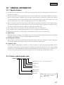
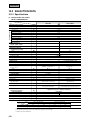
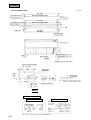
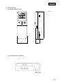
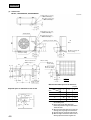
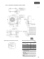
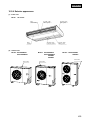
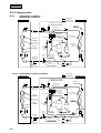
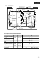
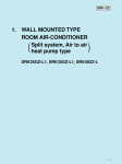
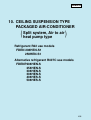
FDEN-H SRK-H 2. CEILING 10. WALL MOUNTED SUSPENSION TYPE TYPE ROOM AIR-CONDITIONER PACKAGED AIR-CONDITIONER Split Split system, system, Air Air to to air air heat heat pump pump type type ( ) SRK328HENF-L2, SRK408HENF-L2 Refrigerant R22 use models SRK501HENF-L, SRK561HENF-L FDEN 208HEN-S1 258HEN-S1 Alternative refrigerant R407C use models FDENP208HEN-S 258HEN-S 308HEN-S 308HEN-S 408HES-S 508HES-S 405 FDEN-H CONTENTS 10.1 GENERAL INFORMATION ........................................................................ 407 10.1.1 Specific features ................................................................................. 407 10.1.2 How to read the model name ............................................................. 407 10.2 SELECTION DATA..................................................................................... 408 10.2.1 Specifications ...................................................................................... 408 10.2.2 Range of usage & limitations ............................................................. 416 10.2.3 Exterior dimensions............................................................................ 417 10.2.4 Exterior appearance............................................................................ 423 10.2.5 Piping system ...................................................................................... 424 10.2.6 Selection chart .................................................................................... 426 10.2.7 Noise level ........................................................................................... 428 10.3 ELECTRICAL DATA................................................................................... 430 10.3.1 Electrical wiring .................................................................................. 430 10.4 OUTLINE OF OPERATION CONTROL BY MICROCOMPUTER ............. 435 10.5 APPLICATION DATA ................................................................................. 435 10.5.1 Installation of indoor unit ................................................................... 436 10.5.2 Installation of outdoor unit................................................................. 439 10.6 MAINTENANCE DATA ............................................................................... 439 406 FDEN-H 10.1 GENERAL INFORMATION 10.1.1 Specific features (1) Less refrigerant charge amount due to use of double phase refrigerant flow system. The total refrigerant charge amount has been reduced by more than 50%. (2) The indoor outdoor interconnection signal wiring has been done away with. The microcomputer chip is installed in the indoor unit. There is no need for the unit to communicate between the outdoor and indoor units so the unit is more resistant to electromagnetic noise thus the incidence of microcomputer malfunction has been reduced. The compressor in the outdoor unit has its own self protection function, that reacts according to abnormal high pressure and excessive high temperature. (3) There are only four power lines between the outdoor and indoor unit. As no signal wire is used there is no need to separate the power line from the signal line. One cab tyre cable with 6 wires encased in one sheath is enough for conducting the wiring work between the outdoor unit and the indoor unit. This contributes to simpler wiring work in the field. (4) All air supply ports have auto swing louvers. The indoor fan motor has two speeds of high and low. (5) The controls are wireless residential split air conditioner type remote controller with 5 malfunction modes. (6) All models have service valves protruding from the outdoor unit for faster flare connection work in the field. (7) Simple design With the model change, the design has been completely renewed. A simple and modern form with curves harmonizes more with the interior. The suction grill also comes in two segments, simplifying the maintenance. (8) Amazingly quiet operation Due to adoption of a newly developed silent stream fan, unpleasant operation sound, such as sound made when the fan runs against the air, has been minimized, thus achieving the trade’s lowest noise level in the weak flow mode. (9) “Aerowing” louver In order to make air conditioning more comfortable, an “aerowing” louver has been newly developed by applying MHI’s advanced aerodynamics, leading to improved air directivity and air conditioning feeling. In the auto swing mode, the louver angle is optimum from 0 (level) to 75°, thus distributing the refreshing air evenly throughout your room. By working the remote controller, you can also set the louver angle easily. The sideways blowout angle can also be set manually up to 45° either right or left side. 10.1.2 How to read the model name Example: FDEN P 20 8 H EN - S Applicable power source ... See the specifications Heat pump type Series No. Product capacity P:R407C model P :R22 model (blank) Model name FDEN: Ceiling suspension type unit with wireless remote controller FDC: Outdoor unit 407 FDEN-H 10.2 SELECTION DATA 10.2.1 Specifications (1) Refrigerant R22 use models Model FDEN208HEN-S1 FDEN208HEN-S1 Model Item FDEN208H Nominal cooling capacity(1) W Nominal heating capacity(1) W FDC208HEN3A 5000 5400 Power source Operation data(3) Cooling input 1 Phase, 220/240V, 50Hz kW 1.77/1.86 Running current (Cooling) A 8.2/8.0 Power factor (Cooling) % 98/97 kW 1.73/1.83 Running current (Heating) A 8.0/7.8 Power factor (Heating) % 98/98 Inrush current (L.R.A) A Heating input Noise level(4) Exterior dimensions Height × Width × Depth Net weight 44 dB(A) Hi: 43 Lo: 38 52 mm 184× 1000 × 650 690 × 880 × 290 kg 22 49 – RM5523GNE4 × 1 Refrigerant equipment Compressor type & Q’ty kW Motor Starting method Heat exchanger – 1.7 – Line starting Louver fines & inner grooved tubing Refrigerant control Refrigerant Quantity Refrigerant oil Slitted fines & bare tubing Capillary tube R22 kg Holding charged r – 0.98 [Pre-charged up to the piping length of 0m] 0.7 (BARREL FREEZE 32SAM) Defrost control MC controlled de-icer High pressure control High pressure switch Air handling equipment Multiblade centrifugal fan × 2 Fan type & Q’ty W Motor Starting method Air flow (Standard) CMM Fresh air intake Air filter, Q’ty Shock & vibration absorber Electric heater Propeller fan × 1 40 × 1 55 × 1 Line starting Line starting Hi:14 Lo:10 56 Unavailable – Polypropylene net × 2 (washable) – Rubber sleeve (for fan motor) Rubber mount (for compressor) – 20 (Crank case heater) Wireless remote control switch – (Indoor unit side) W Operation control Operation switch Room temperature control Safety equipment Installation data Refrigerant piping size Thermostat by electronics – Internal thermostat for fan motor. Internal thermostat for fan motor. Frost protection thermostat. Abnormal discharge temperature protection mm Liquid line: φ6.35 (1/4″) Gas line: φ15.88 (5/8″) (in) Connecting method Drain hose Flare piping (Connectable with VP20) Insulation for piping Accessories – Necessary (both Liquid & Gas lines) Mounting kit. Wireless remote controller Optional parts Notes (1) The data are measured at the following conditions. Item Indoor air temperature Operation DB WB Cooling 27˚C 19˚C Heating 20˚C – – Outdoor air temperature DB WB 35˚C 24˚C 7˚C 6˚C Standards ISO-T1, JIS B8616 (2) This packaged air-conditioner is manufactured and tested in conformity with the following standard. JIS B8616 “UNITARY AIR-CONDITIONERS” (3) The operation data indicate when the air-conditioner is operated at 220/240V 50Hz. (4) Indicates the value at mild mode . 408 FDEN-H Model FDEN258HEN-S1 FDEN258HEN-S1 Model Item FDEN258H Nominal cooling capacity(1) W Nominal heating capacity(1) W FDC258HEN3A 5700 6100 Power source 1 Phase, 220/240V, 50Hz Operation data(3) Cooling input kW 2.04/2.15 Running current (Cooling) A 9.4/9.4 Power factor (Cooling) % 99/95 kW 1.94/2.09 Running current (Heating) A 9.1/9.2 Power factor (Heating) % 97/95 Inrush current (L.R.A) A Heating input Noise level(4) Exterior dimensions Height × Width × Depth Net weight 51 dB(A) Hi: 44 Lo: 39 52 mm 184 × 1260 × 650 845 × 880 × 340 kg 27 55 – RM5526GNE4 × 1 Refrigerant equipment Compressor type & Q’ty kW Motor Starting method Heat exchanger – 1.9 – Line starting Louver fines & inner grooved tubing Refrigerant control Slitted fines & bare tubing Capillary tube Refrigerant R22 Quantity Refrigerant oil kg Holding charged r – 1.1 [Pre-charged up to the piping length of 5m] 0.7 (BARREL FREEZE 32SAM) Defrost control MC controlled de-icer High pressure control High pressure switch Air handling equipment Multiblade centrifugal fan × 4 Fan type & Q’ty 25 × 2 55 × 1 Line starting Line starting Hi: 16 Lo: 10.5 56 W Motor Starting method Air flow (Standard) CMM Fresh air intake Air filter, Q’ty Shock & vibration absorber Electric heater Propeller fan × 1 Unavailable – Polypropylene net ×2 (washable) – Rubber sleeve (for fan motor) Rubber mount (for compressor) – 20 (Crank case heater) Wireless remote control switch – (Indoor unit side) W Operation control Operation switch Room temperature control Safety equipment(5) Installation data Thermostat by electronics – Internal thermostat for fan motor. Internal thermostat for fan motor. Frost protection thermostat. Abnormal discharge temperature protection mm Refrigerant piping size Liquid line: φ9.52 (3/8″) Gas line: φ15.88 (5/8″) (in) Connecting method Flare piping Drain hose (Connectable with VP20) Insulation for piping – Necessary (both Liquid & Gas lines) Accessories Mounting kit. Wireless remote controller Optional parts – Notes (1) The data are measured at the following conditions. Item Operation Cooling Heating Indoor air temperature DB WB 27˚C 19˚C 20˚C – Outdoor air temperature DB WB 35˚C 24˚C 7˚C 6˚C Standards ISO-T1, JIS B8616 (2) This packaged air-conditioner is manufactured and tested in conformity with the following standard. JIS B8616 “UNITARY AIR-CONDITIONERS” (3) The operation data indicate when the air-conditioner is operated at 220/240V 50Hz. (4) Indicates the value at mild mode. 409 FDEN-H (2) Alternative refrigerant R407C use models Model FDENP208HEN-S FDENP208HEN-S Model Item FDEN208H Nominal cooling capacity(1) W Nominal heating capacity(1) W FDCP208HEN3A 5000 5400 Power source Operation data(3) Cooling input 1 Phase, 220/240V, 50Hz kW 2.08/2.15 Running current (Cooling) A 9.5/9.6 Power factor (Cooling) % 99/93 kW 1.98/2.12 Running current (Heating) A 9.3/9.5 Power factor (Heating) % 97/93 Inrush current (L.R.A) A Heating input Noise level(4) Exterior dimensions Height × Width × Depth Net weight 55 dB(A) Hi: 43 Lo: 38 52 mm 184× 1000 × 650 690 × 880 × 290 kg 22 49 – RM5523HNE5 × 1 Refrigerant equipment Compressor type & Q’ty Motor kW Starting method Heat exchanger – 1.7 – Line starting Louver fines & inner grooved tubing Refrigerant control Refrigerant Quantity Refrigerant oil Slitted fines & bare tubing Capillary tube R407C kg Holding charged r – 0.98 [Pre-charged up to the piping length of 0m] 0.7 (MA32) Defrost control MC controlled de-icer High pressure control High pressure switch Air handling equipment Multiblade centrifugal fan × 2 Fan type & Q’ty Motor W Starting method Air flow (Standard) CMM Fresh air intake Air filter, Q’ty Shock & vibration absorber Electric heater Propeller fan × 1 40 × 1 55 × 1 Line starting Line starting Hi:14 Lo:10 56 Unavailable – Polypropylene net × 2 (washable) – Rubber sleeve (for fan motor) Rubber mount (for compressor) – 20 (Crank case heater) Wireless remote control switch – (Indoor unit side) W Operation control Operation switch Room temperature control Safety equipment Installation data Refrigerant piping size Thermostat by electronics – Internal thermostat for fan motor. Internal thermostat for fan motor. Frost protection thermostat. Thermostat for discharge temperature. mm Liquid line: φ6.35 (1/4″) Gas line: φ15.88 (5/8″) (in) Connecting method Drain hose Flare piping (Connectable with VP20) Insulation for piping Accessories – Necessary (both Liquid & Gas lines) Mounting kit. Wireless remote controller Optional parts Notes (1) The data are measured at the following conditions. Item Indoor air temperature Operation DB WB Cooling 27˚C 19˚C Heating 20˚C – – Outdoor air temperature DB WB 35˚C 24˚C 7˚C 6˚C Standards ISO-T1, JIS B8616 (2) This packaged air-conditioner is manufactured and tested in conformity with the following standard. JIS B8616 “UNITARY AIR-CONDITIONERS” (3) The operation data indicate when the air-conditioner is operated at 220/240V 50Hz. (4) Indicates the value at mild mode . 410 FDEN-H Model FDENP258HEN-S FDENP258HEN-S Model Item FDEN258H Nominal cooling capacity(1) W Nominal heating capacity(1) W FDCP258HEN3A 5700 6100 Power source 1 Phase, 220/240V, 50Hz Operation data(3) Cooling input kW 2.35/2.55 Running current (Cooling) A 11.4/12.6 Power factor (Cooling) % 94/84 kW 2.09/2.34 Running current (Heating) A 10.5/12.0 Power factor (Heating) % 90/81 Inrush current (L.R.A) A Heating input Noise level(4) Exterior dimensions Height × Width × Depth Net weight 63 dB(A) Hi: 44 Lo: 39 52 mm 184 × 1260 × 650 845 × 880 × 340 kg 27 55 – RM5526HNE5 × 1 Refrigerant equipment Compressor type & Q’ty Motor kW Starting method Heat exchanger – 1.9 – Line starting Louver fines & inner grooved tubing Refrigerant control Slitted fines & bare tubing Capillary tube Refrigerant R407C Quantity Refrigerant oil kg Holding charged r – 1.2 [Pre-charged up to the piping length of 5m] 0.7 (MA32) Defrost control MC controlled de-icer High pressure control High pressure switch Air handling equipment Multiblade centrifugal fan × 4 Fan type & Q’ty Motor 25 × 2 55 × 1 Line starting Line starting Hi: 16 Lo: 10.5 56 W Starting method Air flow (Standard) CMM Fresh air intake Air filter, Q’ty Shock & vibration absorber Electric heater Propeller fan × 1 Unavailable – Polypropylene net ×2 (washable) – Rubber sleeve (for fan motor) Rubber mount (for compressor) – 20 (Crank case heater) Wireless remote control switch – (Indoor unit side) W Operation control Operation switch Room temperature control Safety equipment(5) Installation data Thermostat by electronics – Internal thermostat for fan motor. Internal thermostat for fan motor. Frost protection thermostat. Thermostat for discharge temperature. mm Refrigerant piping size Liquid line: φ9.52 (3/8″) Gas line: φ15.88 (5/8″) (in) Connecting method Flare piping Drain hose (Connectable with VP20) Insulation for piping – Necessary (both Liquid & Gas lines) Accessories Mounting kit. Wireless remote controller Optional parts – Notes (1) The data are measured at the following conditions. Item Operation Cooling Heating Indoor air temperature DB WB 27˚C 19˚C 20˚C – Outdoor air temperature DB WB 35˚C 24˚C 7˚C 6˚C Standards ISO-T1, JIS B8616 (2) This packaged air-conditioner is manufactured and tested in conformity with the following standard. JIS B8616 “UNITARY AIR-CONDITIONERS” (3) The operation data indicate when the air-conditioner is operated at 220/240V 50Hz. (4) Indicates the value at mild mode. 411 FDEN-H Model FDENP308HEN-S FDENP308HEN-S Model Item FDEN308H Nominal cooling capacity(1) W Nominal heating capacity(1) W FDCP308HEN3 7100 8000 Power source 1 Phase, 220/240V, 50Hz Cooling input Operation data(3) Running current (Cooling) Power factor (Cooling) kW 3.22/3.37 A 14.9/15.3 % 98/92 kW 2.97/3.11 Running current (Heating) A 13.9/14.3 Power factor (Heating) % 97/91 Inrush current (L.R.A) A Heating input Noise level(4) Exterior dimensions Height × Width × Depth Net weight 95 dB(A) Hi 45 Lo:39 52 mm 184 × 1260 × 650 845 × 880 × 340 kg 27 76 – GT-A5534HN41 × 1 Refrigerant equipment Compressor type & Q’ty Motor kW Starting method Heat exchanger – 2.5 – Line starting Louver fins & inner grooved tubing Refrigerant control Slitted fins & bare tubing Capillary tube Refrigerant R407C Quantity Refrigerant oil kg Holding charged r – 1.75 [Pre-charged up to the piping length of 5m] 1.45 (MA32) Defrost control MC controlled de-icer High pressure control High pressure switch Air handling equipment Multiblade centrifugal fan × 4 Fan type & Q’ty Motor 35 × 2 55 × 1 Line starting Line starting Hi:16.5 Lo:11.5 58 W Starting method Air flow (Standard) CMM Fresh air intake Air filter, Q’ty Shock & vibration absorber Electric heater Propeller fan × 1 Unavailable – Polypropylene net ×2(washable) – Rubber sleeve (for fan motor) Rubber mount (for compressor) – 33 (Crank case heater) Wireless remote control switch – (Indoor unit side) W Operation control Operation switch Room temperature control Safety equipment Installation data Thermostat by electronics – Internal thermostat for fan motor. Internal thermostat for fan motor. Frost protection thermostat. Thermistor for discharge temperature. mm Refrigerant piping size Liquid line: φ9.52 (3/8″) Gas line: φ15.88 (5/8″) (in) Connecting method Flare piping Drain hose (Connectable with VP20) Insulation for piping – Necessary (both Liquid & Gas lines) Accessories Mounting kit. Wireless remote controller. Optional parts – Notes (1) The data are measured at the following conditions. Item Operation Cooling Heating Indoor air temperature DB WB 27˚C 19˚C 20˚C – Outdoor air temperature DB WB 35˚C 24˚C 7˚C 6˚C Standards ISO-T1, JIS B8616 (2) This packaged air-conditioner is manufactured and tested in conformity with the following standard. JIS B8616 “UNITARY AIR-CONDITIONERS” (3) The operation data indicate when the air-conditioner is operated at 220/240V 50Hz. (4) Indicates the value at mild mode. 412 FDEN-H Model FDENP308HES-S FDENP308HES-S Model Item FDEN308H Nominal cooling capacity(1) W Nominal heating capacity(1) W FDCP308HES3 7100 8000 Power source 3 Phase, 380/415V 50Hz Operation data(3) Cooling input kW 3.14/3.29 Running current (Cooling) A 5.5/5.8 Power factor (Cooling) % 87/79 kW 2.99/3.13 Running current (Heating) A 5.5/5.8 Power factor (Heating) % 83/75 Inrush current (L.R.A) A Heating input Noise level(4) Exterior dimensions Height × Width × Depth Net weight 45 dB(A) Hi:45 Lo:39 52 mm 184 × 1260 × 650 845 × 880 × 340 kg 27 76 – GT-A5534ES41 × 1 Refrigerant equipment Compressor type & Q’ty Motor kW Starting method Heat exchanger – 2.5 – Line starting Louver fins & inner grooved tubing Refrigerant control Slitted fins & bare tubing Capillary tube Refrigerant R407C Quantity Refrigerant oil kg Holding charged r – 1.75 [Pre-charged up to the piping length of 5m] 1.45 (MA32) Defrost control IC controlled de-icer High pressure control High pressure switch Air handling equipment Multiblade centrifugal fan × 4 Fan type & Q’ty Motor 35 × 2 55 × 1 Line starting Line starting Hi:16.5 Lo:11.5 58 W Starting method Air flow (Standard) CMM Fresh air intake Air filter, Q’ty Shock & vibration absorber Electric heater Propeller fan × 1 Unavailable – Polypropylene net ×2(washable) – Rubber sleeve (for fan motor) Rubber mount (for compressor) – 33 (Crank case heater) Wireless remote control switch – (Indoor unit side) W Operation control Operation switch Room temperature control Safety equipment Installation data Thermostat by electronics – Internal thermostat for fan motor. Internal thermostat for fan motor. Frost protection thermostat. Thermistor for discharge temperature. mm Refrigerant piping size Liquid line: φ9.52 (3/8″) Gas line: φ15.88 (5/8″) (in) Connecting method Flare piping Drain hose (Connectable with VP20) Insulation for piping – Necessary (both Liquid & Gas lines) Accessories Mounting kit. Wireless remote controller. Optional parts – Notes (1) The data are measured at the following conditions. Item Operation Cooling Heating Indoor air temperature DB WB 27˚C 19˚C 20˚C – Outdoor air temperature DB WB 35˚C 24˚C 7˚C 6˚C Standards ISO-T1 JIS B8616 (2) This packaged air-conditioner is manufactured and tested in conformity with the following standard. JIS B8616 “UNITARY AIR-CONDITIONERS” (3) The operation data indicate when the air-conditioner is operated at 380/415V 50Hz. (4) Indicates the value at mild mode. 413 FDEN-H Model FDENP408HES-S FDENP408HES-S Model Item FDEN408H Nominal cooling capacity(1) W Nominal heating capacity(1) W FDCP408HES3 10000 11200 Power source 3 Phase, 380/415V 50Hz Operation data(3) Cooling input kW 4.51/4.63 Running current (Cooling) A 7.8/8.2 Power factor (Cooling) % 88/79 kW 4.35/4.47 Running current (Heating) A 7.8/8.2 Power factor (Heating) % 85/76 Inrush current (L.R.A) A Heating input Noise level(4) Exterior dimensions Height × Width × Depth Net weight 53 dB(A) Hi: 49 Lo:43 54 mm 239 × 1260 × 650 1050 × 920 × 340 kg 34 98 – GU-A5550HS41 × 1 Refrigerant equipment Compressor type & Q’ty Motor kW Starting method Heat exchanger – 2.8 – Line starting Louver fins & inner grooved tubing Refrigerant control Slitted fins & bare tubing Capillary tube Refrigerant R407C Quantity Refrigerant oil kg Holding charged r – 2.12 [Pre-charged up to the piping length of 5m] 1.6 (MA32) Defrost control MC controlled de-icer High pressure control High pressure switch Air handling equipment Multiblade centrifugal fan × 3 Fan type & Q’ty Motor W Starting method Air flow (Standard) CMM Fresh air intake Air filter, Q’ty Shock & vibration absorber Electric heater Propeller fan × 2 35+ 55 40 × 2 Line starting Line starting Hi:26 Lo:19 70 Unavailable – Polypropylene net ×3(washable) – Rubber sleeve (for fan motor) Rubber mount (for compressor) – 40 (Crank case heater) Wireless remote control switch – (Indoor unit side) W Operation control Operation switch Room temperature control Safety equipment Installation data Thermostat by electronics – Internal thermostat for fan motor. Internal thermostat for fan motor. Frost protection thermostat. Thermistor for discharge temperature. mm Refrigerant piping size Liquid line: φ9.52 (3/8″) Gas line: φ19.05 (3/4″) (in) Connecting method Flare piping Drain hose (Connectable with VP20) Insulation for piping – Necessary (both Liquid & Gas lines) Accessories Mounting kit. Wireless remote controller. Optional parts – Notes (1) The data are measured at the following conditions. Item Operation Cooling Heating Indoor air temperature DB WB 27˚C 19˚C 20˚C – Outdoor air temperature DB WB 35˚C 24˚C 7˚C 6˚C Standards ISO-T1, JIS B8616 (2) This packaged air-conditioner is manufactured and tested in conformity with the following standard. JIS B8616 “UNITARY AIR-CONDITIONERS” (3) The operation data indicate when the air-conditioner is operated at 380/415V 50Hz. (4) Indicates the value at mild mode. 414 FDEN-H Model FDENP508HES-S FDENP508HES-S Model Item FDEN508H Nominal cooling capacity(1) W Nominal heating capacity(1) W FDCP508HES3 12500 14000 Power source 3 Phase, 380/415V 50Hz Operation data(3) Cooling input kW 5.36/5.43 Running current (Cooling) A 9.5/9.8 Power factor (Cooling) % 86/77 kW 5.24/5.31 Running current (Heating) A 9.4/9.7 Power factor (Heating) % 84/76 Inrush current (L.R.A) A Heating input Noise level(4) Exterior dimensions Height × Width × Depth Net weight 74 dB(A) Hi:50 Lo:44 55 mm 239 × 1470 × 650 1250 × 920 × 340 kg 40 107 – GU-A5560HS41 × 1 Refrigerant equipment Compressor type & Q’ty Motor kW Starting method Heat exchanger – 3.75 – Line starting Louver fins & inner grooved tubing Refrigerant control Slitted fins & bare tubing Capillary tube Refrigerant R407C Quantity Refrigerant oil kg Holding charged r – 2.58 [Pre-charged up to the piping length of 5m ] 1.6 (MA32) Defrost control MC controlled de-icer High pressure control High pressure switch Air handling equipment Multiblade centrifugal fan × 4 Fan type & Q’ty Motor W Starting method Air flow (Standard) CMM Fresh air intake Air filter, Q’ty Shock & vibration absorber Electric heater Propeller fan × 2 55 × 2 65 × 2 Line starting Line starting Hi:28 Lo:20 110 Unavailable – Polypropylene net ×3(washable) – Rubber sleeve (for fan motor) Rubber mount (for compressor) – 40 (Crank case heater) Wireless remote control switch – (Indoor unit side) W Operation control Operation switch Room temperature control Safety equipment Installation data Thermostat by electronics – Internal thermostat for fan motor. Internal thermostat for fan motor. Frost protection thermostat. Thermistor for discharge temperature. mm Refrigerant piping size Liquid line: φ9.52 (3/8″) Gas line: φ19.05 (3/4″) (in) Connecting method Flare piping Drain hose (Connectable with VP20) Insulation for piping – Necessary (both Liquid & Gas lines) Accessories Mounting kit. Wireless remote controller. Optional parts – Notes (1) The data are measured at the following conditions. Item Operation Cooling Heating Indoor air temperature DB WB 27˚C 19˚C 20˚C – Outdoor air temperature DB WB 35˚C 24˚C 7˚C 6˚C Standards ISO-T1, JIS B8616 (2) This packaged air-conditioner is manufactured and tested in conformity with the following standard. JIS B8616 “UNITARY AIR-CONDITIONERS” (3) The operation data indicate when the air-conditioner is operated at 380/415V 50Hz. (4) Indicates the value at mild mode. 415 FDEN-H 10.2.2 Range of usage & limitations Models Item FDENP208, 258 type FDENP308~508 type Indoor return air temperature (Upper, lower limits) Refer to the selection chart Outdoor air temperature (Upper, lower limits) Refrigerant line (one way) length Vertical height difference between outdoor unit and indoor unit Power source voltage Max. 30 m Max. 50 m Max. 20 m (Outdoor unit is higher) Max. 30 m (Outdoor unit is higher) Max. 15 m (Outdoor unit is lower) Max. 15 m (Outdoor unit is lower) Rating ± 10% Voltage at starting Min. 85% of rating Frequency of ON-OFF cycle Max. 10 times/h ON and OFF interval Max. 3 minutes 416 FDEN-H 10.2.3 Exterior dimensions (1) Indoor unit Models FDEN208H, 258H, 308H 1244 [984] 15 15 (Holes for suspension bolt) ) 50 1160 [900] 50 Side panel 7 15 10 20 30 10 1200 [940] 1260 [1000] ↑ 135 ) ( Unit: mm Holes for suspension bolts (12 × 17 × 4 pcs.) (Holes for suspension bolt) The brackets face interior When the unit is suspended beneath the ceiling A 20 30 Air outlet grille (Automatic louver) 290 Indication board Air inlet grille Air filter 35 Drain 30 Liquid piping Gas piping 18 75 10 94 46 570 75 18 Note (1) The slope of drain piping inside the unit is able to take incline of 10 mm. 650 195 225 248 (Liq.) (Gas) (Drain) Drain piping connection VIEW A Space for installation & servicing Piping & wiring draw out holes Top exit 100mm or more 300mm or more 80 Drain piping connection 46 135 34 275 150 37 208: ø6.35 (1/4˝) Liquid piping 258, 308: ø9.52 (3/8˝) Gas piping ø15.88 (5/8") 30 Drain (Connectable with VP20) 31 195 34 20 45 184 20 55 Holes for suspension bolt (12 x 17 x 4 pcs.) 605 5 20 70 ( The brackets face out When the unit is half recessed above the ceiling 150mm or more Obstacles ( 5mm or more ref. piping & wiring ) Right exit (piping & wiring ) 70 11 75 18 Left exit ( piping & wiring Rear exit ) Left exit drain (piping & wiring ) ( piping ) Note (1) The [ ] value dimension for models FDEN208H. 417 FDEN-H Unit: mm Models FDEN408H, 508H 15 1451 [1244] The brackets face out (Holes for suspension bolt) Holes for suspension bolts ) (Holes for suspension bolt) ) 135 ( 15 The brackets face interior When the unit is suspended beneath the ceiling (12 × 17 × 4pcs.) 50 1370 [1160] 50 20 Side panel 10 10 1410 [1200] 1470 [1260] 30 ↑ When the unit is half recessed above the ceiling 7 ( 15 A 20 30 Air outlet grille (Automatic louver) 290 Indication board Drain 29 35 Air inlet grille Air filter 30 55 Liquid piping ø9.52 (3/8") Gas piping ø19.05 (3/4") 30 Drain (Connectable with VP20) Holes for suspension bolts (12 × 17 × 4pcs.) 66 584 174 5 275 Liquid piping Gas piping 135 18 75 10 31 75 18 650 196 225 266 Note (1) The slope of drain piping inside the unit is able to take incline of 10 mm. Drain hole connection (Liq.) (Gas) (Drain) VIEW A Space for installation & servicing Piping & wiring draw out holes Ceiling suspension installation Top exit ref. piping & wiring 300mm min ( 100mm min Obstacles 150mm min 5mm min ) Right exit piping & wiring ( Note (1) The [ ] value dimension for models FDEN408H 418 Drain piping Connection 46 20 570 20 70 94 80 46 37 239 150 89 34 ) Left exit piping & wiring Rear exit Left exit drain piping piping & wiring ( ( )( ) ) FDEN-H (2) Remote controller (a) Wireless remote controller Unit: mm AUTO COOL DRY FAN HEAT FAN HI LO FILTER °C ON AM PM TEMP ON/OFF 161.5 MODE OFF AM PM 60 20.5 (b) Indication board of indoor unit Remote controller signal receiver 419 FDEN-H (3) Outdoor unit Models, FDC208HEN3A, FDCP208HEN3A Unit: mm 40 53 40 Liquid piping:ø6.35 (1/4") (Flare connecting) Gas piping:ø15.88 (5/8") (Flare connecting) 95 Liquid piping:ø6.35 (1/4") (Flare connecting) Terminal block Gas piping:ø15.88 (5/8") (Flare connecting) A 351 311 40 50 Opening for piping and electric wiring 50 50 Opening for piping and electric wiring 195 10 195 110 690 110 Opening for electric wiring 15 50 27 50 880 150 70 15 103 50 40 35 290 35 Opening for piping and electric wiring 55 15 330 150 15 Electric wiring Opening for electric wiring Holes for anchor bolt (M10 × 4 pcs.) 580 150 55 50 335 260 15 15 50 40 VIEW A Holes for drain (ø20 × 3 pcs.) Minimum allowable space to the obstacles Unit:mm Installation type Required space for maintenance and air flow 1 2 3 L1 Open Open 500 L2 300 5 Open L3 100 150 100 L4 5 5 5 Mark L3 L2 Air inlet L4 Air inlet L1 ( Maintenance ) space 420 Air outlet Notes (1) Avoid the location where four sides are entirely surrounded by walls. (2) Fix the unit by anchor bolts without fail. Restrict the protrusion length of anchor bolt to 15 mm and under. (3) When strong wind blows against the unit, direct the discharge port at a right angle to the wind direction. (4) Secure the space of 1 m and over at the top of unit. (5) Make the height of obstruction wall in front of discharge port lower than the height of unit. FDEN-H Models FDC258HEN3A, FDCP258HEN3A, 308HEN3, 308HES3 Unit: mm Liquid piping: ø9.52 (3/8") (Flare connecting) 53 40 Gas piping: ø15.88 (5/8") (Flare connecting) 40 95 Terminal block Liquid piping: ø9.52 (3/8") (Flare connecting) 110 195 50 50 10 195 460 110 845 Gas piping: ø15.88 (5/8") (Flare connecting) Opening for electric wiring Opening for electric wiring Opening for piping and electric wiring 50 40 50 27 15 Opening for piping and electric wiring 50 880 Holes for anchor bolt (M10 × 4 pcs.) 580 150 15 35 103 70 Opening for piping and electric wiring 40 50 222 50 47 340 35 55 380 15 Electric wiring 150 15 150 15 50 15 50 Holes for drain (ø9.52 × 3pcs.) 310 VIEW A Required space for maintenance and air flow Minimum allowable space to the obstacles Unit:mm L3 L2 Installation type Air inlet L4 Air inlet L1 Maintenance space Air outlet 1 2 3 L1 Open Open 500 L2 300 5 Open L3 100 150 100 L4 5 5 5 Mark Notes (1) Avoid the location where four sides are entirely surrounded by walls. (2) Fix the unit by anchor bolts without fail. Restrict the protrusion length of anchor bolt to 15 mm and under. (3) When strong wind blows against the unit, direct the discharge port at a right angle to the wind direction. (4) Secure the space of 1 m and over at the top of unit. (5) Make the height of obstruction wall in front of discharge port lower than the height of unit. 421 FDEN-H Models FDCP408HES3, 508HES3 Unit: mm Liquid piping: ø 9.52 (3/8") (Flare connecting) 46 100 48 50 Gas piping: ø 19.05 (3/4") (Flare connecting) Terminal block Liquid piping: ø 9.52 (3/8") (Flare connecting) 1250 (1050) Gas piping: ø 19.05 (3/4") (Flare connecting) Opening for electric wiring A 55 50 110 578 195 50 Opening for piping and electric wiring 50 10 195 110 555 Opening for electric wiring 50 50 27 15 Opening for piping and electric wiring 920 Holes for anchor bolt (M10 × 4pcs.) 580 175 15 103 295 50 15 Holes for drain (ø 20 × 3pcs.) 50 237 Opening for piping and electric wiring 70 50 Electric wiring 150 47 35 35 55 15 380 340 15 165 Note (1) The ( ) value dimension for model FDCP408HES3. Required space for maintenance and air flow 15 Opening for electric wiring 40 50 VIEW A Minimum allowable space to the obstacles Unit:mm L3 L2 Installation type Air inlet L4 Air inlet L1 Maintenance space Air outlet 1 2 3 L1 Open Open 500 L2 300 5 Open L3 150 300 150 L4 5 5 5 Mark Notes (1) Avoid the location where four sides are entirely surrounded by walls. (2) Fix the unit by anchor bolts without fail. Restrict the protrusion length of anchor bolt to 15 mm and under. (3) When strong wind blows against the unit, direct the discharge port at a right angle to the wind direction. (4) Secure the space of 1 m and over at the top of unit. (5) Make the height of obstruction wall in front of discharge port lower than the height of unit. 422 FDEN-H 10.2.4 Exterior appearance (1) Indoor unit Model All models Gray (Vertical lins) Ceramic white (Front panel) Gray (Frame) (2) Outdoor unit Models FDC208HEN3A FDCP208HEN3A Ceramic white (Air inlet louver) Models FDC258HEN3A FDCP258HEN3A 308HEN3 308HES3 Ceramic white (Side panel) Ceramic white (Front panel) Models FDCP408HES3 508HES3 Polar white Polar white Polar white 423 FDEN-H 10.2.5 Piping system Models FDEN208HEN-S1, 258HEN-S1 FDENP208HEN-S, 258HEN-S Cooling cycle Indoor unit Heating cycle Outdoor unit High pressure switch (63H2) (For fan motor control) Thermistor (ThO-A) 4way valve Gas line (ø15.88) Strainer Service valve (Flare connecting) Thermistor High pressure switch (63H1) (Only case of FDENP model) Check joint Check joint Heat exchanger (ThI-A) Heat exchanger Thermistor Thermistor (ThI-R) (ThO-R) Muffler Solenoid valve (SV1) Compressor Liquid line 208:ø6.35 258:ø9.52 ( Accumulators Subcooling coil Capillary tube Capillary tube Thermistor (ThO-D) Check joint Strainer ) Check valve Strainer Strainer Service valve (Flare connecting) Flare connecting Capillary tube Models FDENP308HEN-S, 308HES-S, 408HES-S Cooling cycle Heating cycle Indoor unit Outdoor unit High pressure switch (63H2) (For fan motor control) Thermistor (ThO-A) 4 way valve Strainer Gas line 308:ø15.88 (408:ø19.05 ) Thermistor (ThI-A) Service valve (Flare connecting) High pressure switch (63H1) Heat exchanger Check joint Check joint Heat exchanger Thermistor (ThI-R) Muffler Solenoid valve Compressor Accumulators Subcooling coil Capillary tube Check joint Thermistor (ThO-D) Liquid line (ø9.52) Strainer Capillary tube Strainer Check valve Solenoid valve Strainer Flare connecting 424 Thermistor (ThO-R) Service valve (Flare connecting) Capillary tube FDEN-H Model FDENP508HES-S High pressure switch (63H2) (For fan motor control) Indoor unit Cooling cycle 4 way valve Strainer Gas line (ø19.05) Service valve (Flare connecting) High pressure switch (63H1) Thermistor (ThO-A) Check joint Heat exchanger Capillary tube Thermistor (ThI-A) Check joint Oil separator Thermistor (ThO-D) Heat exchanger Capillary tube Thermistor (ThI-R) Compressor Capillary tube Outdoor unit Heating cycle Check joint Capillary tube Liquid line (ø9.52) Strainer Accumulators Subcooling coil Solenoid valve (SV1) Strainer Solenoid Thermistor valve (SV2) (ThO-R) Check valve Strainer Service valve (Flare connecting) Capillary tube Flare connecting Preset point of the protective devices Parts name Thermistor (for protection over loading in heating) Mark ThI-R Equipped unit FDEN208, 258 type FDENP208~258 type OFF ON 68 °C 61 °C OFF ON 2.5 °C 10 °C Indoor unit Thermistor (for frost prevention) Thermistor (for detecting discharge pipe temp.) ThO-D Outdoor unit OFF ON 135 °C 90 °C Thermistor (for detecting heat exchange temp.) ThO-R Outdoor unit OFF ON 70 °C 60 °C High pressure switch (for controlling FMo) 63H2 Outdoor unit High pressure switch (for protection) 63H1 Outdoor unit OFF 2.5MPa (25.5kgf/cm2) ON 2.06MPa (21kgf/cm2) OFF 3.24MPa (33kgf/cm2) ON 2.65MPa (27kgf/cm2) 425 FDEN-H 10.2.6 Selsction chart Correct the cooling and heating capacity in accordance with the conditions as follows. The net cooling and heating capacity can be obtained in the following way. Net capacity = Capacity shown on specification ¥ Correction factors as follows. (1) Coefficient of cooling and heating capacity in relation to temperatures Cooling operation Heating operation Indoor air D.B. temperature (˚CD.B.) Outdoor air D.B. temperature (˚CD.B.) Coefficient of cooling and heating capacity in relation to temperatures Models FDEN208HEN-S1, 258HEN-S1, FDENP208HEN-S, 258HEN-S Indoor air W.B. temperature (˚CW.B.) ISO-T1 Standard condition Outdoor air W.B. temperature (˚CW.B.) Cooling operation Outdoor air D.B. temperature (˚CD.B.) Heating operation Indoor air D.B. temperature (˚CD.B.) Coefficient of cooling and heating capacity in relation to temperatures Models FDENP308HEN-S, 308HES-S, 408HES-S, 508HES-S Indoor air W.B. temperature (˚CW.B.) ISO-T1 Standard condition ISO-T1 Standard condition Outdoor air W.B. temperature (˚CW.B.) 426 FDEN-H Table of bypass factor Model FDEN (P) 208 type FDEN (P) 258 type FDENP308 type FDENP408,508 type Hi 0.031 0.030 0.036 0.018 Lo 0.016 0.013 0.018 0.010 Item Air flow (2) Correction of cooling and heating capacity in relation to air flow rate control (fan speed) Coefficient: 1.00 at High, 0.95 at Low (3) Correction of cooling and heating capacity in relation to one way length of refrigerant piping It is necessary to correct the cooling and heating capacity in relation to the one way equivalent piping length between the indoor and outdoor units. Equivalent piping length(1) m 5 10 15 20 25 30 35 40 45 50 55 1.0 1.0 1.0 1.0 1.0 0.995 0.995 0.99 0.99 0.985 0.985 1.0 0.995 0.995 0.99 0.985 0.985 0.98 1.0 0.995 0.99 0.985 0.98 0.975 0.97 FDENP308 type 1.0 0.99 0.98 0.97 0.96 0.95 0.94 0.93 0.92 0.91 0.9 FDENP408 type 1.0 0.995 0.985 0.98 0.97 0.965 0.955 0.95 0.94 0.935 0.925 FDENP508 type 1.0 0.99 0.975 0.965 0.95 0.94 0.925 0.915 0.9 0.89 0.875 Heating Cooling FDEN208 type FDENP208 type FDEN258 type FDENP258 type Note (1) Equivalent piping length can be obtained by calculating as follows. 208, 258, 308 series [ø15.88(5/8")]: Equivalent piping length = Real piping length + (0.10 × Number or bends in piping) 408, 508, series [ø19.05(3/4")]: Equivalent piping length = Real piping length + (0.15 × Number of bends in piping) [Equivalent piping length < Limitation length of piping + 5m] (4) When the outdoor unit is located at a lower height than the indoor unit in cooling operation and when the outdoor unit is located at a higher height than the indoor unit in heating operation, the following values should be subtracted from the values in the above table. Height difference between the indoor unit and outdoor unit in the vertical heigh sifference 5m 10m 15m 20m 25m 30m Adjustment coefficient 0.01 0.02 0.03 0.04 0.05 0.06 Piping length limitations FDEN208, 258 type FDENP208, 258 type Model Item Max. one way piping length Max. vertical height difference FDENP308, 408, 508 type 30m 50m 20m (Outdoor unit is higher ) 15m (Outdoor unit is lower ) 30m (Outdoor unit is higher ) 15m (Outdoor unit is lower) Note(1) Values in the table indicate the one way piping length between the indoor and outdoor units. How to obtain the cooling capacity Example: The net cooling capacity of the model FDENP308HEN-S with the air flow “High”, the piping length of 15m, the outdoor unit located 5m lower than the indoor unit, indoor wet-bulb temperature at 19.0 ˚C and outdoor dry-bulb temperature 35 ˚C is Net cooling capacity = 7100 × FDENP308HEN-S 1.00 Air flow “High” × (0.98 - 0.01) × Length 15m. Height difference 5 m 1.0 = 6887 w Factor by air temperatures 427 FDEN-H 10.2.7 Noise level Notes (1) The data are based on the following conditions. Ambient air temperature: Indoor unit 27˚C DB, 19˚C WB. Outdoor unit 35˚C DB. Outdoor unit Measured based on JIS B 8616 Mike position: at highest noise level in position as below Distance from front side 1m Height 1m Indoor unit Measured based on JIS B 8616 Mike position as below 1m Unit 1m Mike (front & at low point) (2) The data in the chart are measured in an unechonic room. (3) The noise levels measured in the field are usually higher than the data because of reflection. (1) Indoor unit Model FDEN208H Model FDEN258H Noise level 43 dB (A) at HIGH 38 dB (A) at LOW 70 70 N50 40 40 N40 30 30 63 125 250 500 N30 1000 2000 60 N60 50 50 N50 40 40 N40 30 30 N30 N2 20 63 125 Mid octave band frequency (Hz) 250 500 1000 2000 Noise level 49 dB (A) at HIGH 49 dB (A) at LOW Noise level 50 dB (A) at HIGH 44 dB (A) at LOW 70 70 60 60 70 N70 60 N60 50 50 N50 40 40 N40 30 30 N30 0 20 125 250 500 1000 2000 60 N60 50 50 N50 40 40 N40 30 30 N30 N2 0 20 8000 4000 Sound pressure level (Standard 0.0002µ bar) dB Sound pressure level (Standard 0.0002µ bar) dB N70 20 63 125 250 500 1000 2000 20 8000 4000 Mid octave band frequency (Hz) Mid octave band frequency (Hz) (2) Outdoor unit Model FDC258HEN3A Model FDC208HEN3A Noise level 52dB (A) Sound pressure level (Standard 0.0002µ bar) dB 70 N70 60 60 N60 50 50 N50 40 40 N40 30 30 N2 N30 0 20 63 428 125 250 500 1000 2000 4000 Mid octave band frequency (Hz) 20 8000 Sound pressure level (Standard 0.0002µ bar) dB Noise level 70 52dB (A) 70 70 N70 60 60 N60 50 50 N50 40 40 N40 30 30 N2 N30 0 20 63 125 250 500 1000 2000 60 60 N60 50 50 N50 40 40 N40 30 30 N30 N2 0 20 63 125 250 500 1000 2000 Mid octave band frequency (Hz) Model FDEN508H 70 63 20 8000 4000 Mid octave band frequency (Hz) Model FDEN408H N2 70 N70 60 0 20 8000 4000 70 Sound pressure level (Standard 0.0002µ bar) dB 50 50 Sound pressure level (Standard 0.0002µ bar) dB Sound pressure level (Standard 0.0002µ bar) dB 60 N60 20 70 N70 60 0 Noise level 45 dB (A) at HIGH 39 dB (A) at LOW 70 N70 N2 Model FDEN308H Noise level 44 dB (A) at HIGH 39 dB (A) at LOW 4000 Mid octave band frequency (Hz) 20 8000 4000 20 8000 FDEN-H Model FDCP208HEN3A Model FDCP258HEN3A Noise level 52dB (A) 70 Models FDCP308HEN3, 308HES3 Noise level 52dB (A) 70 70 70 50 50 N50 40 40 N40 30 30 0 20 63 125 250 500 60 N60 50 50 N50 40 40 N40 30 30 N30 N2 1000 2000 4000 0 20 20 8000 63 125 Mid octave band frequency (Hz) 250 500 1000 2000 Noise level 70 70 60 60 N60 50 50 N50 40 40 N40 30 30 0 20 1000 50 N50 40 40 N40 30 30 N30 N2 0 20 63 125 250 500 1000 2000 4000 20 8000 55dB (A) 70 60 N60 50 50 N50 40 40 N40 30 30 N30 N2 500 50 N70 Souud pressure level (standard 0.0002µbar) Sound pressure level (Standard 0.0002µ bar) dB 60 250 60 N60 Mid octave band frequency (Hz) N70 125 60 Model FDCP508HES3 54dB (A) 70 63 20 8000 4000 Mid octave band frequency (Hz) Model FDCP408HES3 Noise level N30 N2 70 N70 60 60 N60 Souud pressure level (standard 0.0002µbar) Sound pressure level (Standard 0.0002µ bar) dB 60 52dB (A) 70 N70 N70 Sound pressure level (Standard 0.0002µ bar) dB Noise level 2000 Mid octave band frequency (Hz) 4000 N30 N2 0 20 8000 20 63 125 250 500 1000 2000 4000 20 8000 Mid octave band frequency (Hz) 429 BL Y/GN RD X02 X05 X01 X06 X03 CT1 R WH WH 3 28 2 Mark CC CFI1,2 CFO CH CM CnA ~ W CT1 F FMI1,2 FMO LED1 LED2 LM PC SV1 SW SW3 TB ThI-A (49FO1) H L UH X02 X03 X04 CF01 X05 16 12 13 17 SV1 21 Mark ThI-R Tho-A Tho-D Tho-R TrI Tro Val Vao 20S 49FI 49FO 52C X1~6 X01~07 63H2 v ■ LED-G LED-R X06 20 A2 19 A1 52C 18 X01 BR Parts name Capacitor for CM Capacitor for FMI Capacitor for FMO Crankcase heater Compressor motor Connector ( mark) Current sensor Fuse Fan motor (Indoor unit) Fan motor (Outdoor unit) Indication lamp (Green - Run) Indication lamp (Yellow - Check) Louver motor Photo coupler Solenoid coil (for control) Switch (ON/OFF) Changeover switch Terminal block ( mark) Thermistor Meaning of marks Printed wiring Board X07 WH CM RD X04 C RD/WH BK/WH S 20S BK Cc OR/WH BK OR/WH FMO1 P 2 P WH 4 BL 1 BL 3 BR/WH 26 27 Tro Parts name Vao 14V CnA1 CnA2 (Checker) CnE 7 6 (Run) LED-G (Check) LED-R CnL Thermistor Thermistor Thermistor Thermistor Transformer (Indoor unit) Transformer (Outdoor unit) Thermistor Varistor 4-way valve solenoid Internal thermostat for FMI Internal thermostat for FMo Magnetic contactor for CM Auxiliary relay Auxiliary relay High pressure switch (for control) Terminal (F) Connector Indication lamp (Green) Indication lamp (Red) X07 25 63H2 BR/WH BL/WH BK/RD BK/WH Tho-R Tho-D Tho-A BK 52C BK BL BR WH OR OR CnM1 BK 2 3 4 5 2/N 3 4 5 Y/GN BR BL BK WH RD Mark BK BL BR GR OR PK RD WH Y Color mark 1 TB TB 1 Y/GN RD/WH BK 12 11 9 13 1 X6 CnF3 X5 PC RD BK N BK/WH DR Outdoor Unit DR CH BR CnR BK/RD PC BL/WH PC RD F(3.15A) OR BK OR BK WH 5 CnF2 OR BK OR BK CFI1 X3 X6 X2 X5 CnF2 6 FMI1 (49FI) WH CnF2 CFI2 H L 7 X3 X1 X4 4 CnJ LM CnJ 3 X1 X2 10 Color Black Blue Brown Gray Orange Pink Red White Yellow Mark BK/RD BK/WH BL/WH BR/WH OR/WH RD/WH Y/GN Color Black/Red Black/White Blue/White Brown/White Orange/White Red/White Yellow/Green TrI RD SW3 8V 14V OFF 1 2 3 4 ON Test BK BR CnW1 CnW2 BK CnQ 220/240V Printed wiring board 8 Val Notes (1) *1 FMI2 is equipped with only for FDEN258HEN-S1 CnF3 FMI2 (49FI) L H CnF3 1 X4 Indoor Unit RD RD XR5 CnL CnB2 CnN XR3 XR1 Wireless remote controller Receiver amp Option ThI–A ThI–R LED1 LED2 SW (3) (3) BK BK CnH2 BK BK BK BK XR4 XR2 Models FDEN208HEN-S1, 258HEN-S1 220/240V GR RD Y/GN RD RD RD PC PC WH TB L Y/GN RD BR WH WH BK BK BK WH OR OR WH WH CnT CnH 430 CnL Power source 1 Phase 220/240V 50Hz FDEN-H 10.3 ELECTRICAL DATA 10.3.1 Electrical wiring WH BL X02 X05 X04 X06 X03 CT1 R WH WH 3 28 2 Mark CC CFI1,2 CFO CH CM CnA ~ W CT1 F FMI1,2 FMO LED1 LED2 LM NR PC SV1 SW SW3 TB ThI-A Y/GN H L UH X02 X03 X04 X05 16 20S 12 13 BK 17 Parts name Capacitor for CM Capacitor for FMI Capacitor for FMO Crankcase heater Compressor motor Connector ( mark) Current sensor Fuse Fan motor (Indoor unit) Fan motor (Outdoor unit) Indication lamp (Green - Run) Indication lamp (Yellow - Timer/Check) Louver motor Surge suppressor Photo coupler Solenoid coil (for control) Switch (ON/OFF) Changeover switch Terminal block ( mark) Thermistor Meaning of marks Printed wiring board X07 S WH CM RD X01 C BK/WH CF01 OR/WH FMO1 (49FO1) BK Cc OR/WH BK BK 2 52C BR X01 SV1 X06 20 Mark ThI-R Tho-A Tho-D Tho-R TrI TrO Val Vao 20S 49FI 49Fo 52C X1~6 X01~07 63H1 63H2 v ■ LED-G LED-R 19 A2 18 A1 P RD 4 BL 52C 21 BL 1 BR/WH 26 27 7 6 Vao Tro 14V CnA1 CnA2 (Checker) CnE 9 8 63H2 BR/WH BL/WH BK/RD Tho-R Tho-D Tho-A (Run) LED-G (Check) LED-R CnL Parts name Thermistor Thermistor Thermistor Thermistor Transformer (Indoor unit) Transformer (Outdoor unit) Va r i s t o r Varistor 4-way valve solenoid Internal thermostat for FMI Internal thermostat for FMo Magnetic contactor for CM Auxiliary relay Auxiliary relay High pressure switch (for protection) High pressure switch (for control) Terminal (F) Connector Indication lamp (Green) Indication lamp (Red) X07 25 63H1 BR 3 BK NR BR BK/WH BK 13 9 11 12 BK BL BR Y/GN 2 3 4 5 2/N 3 4 5 Mark BK BL BR GR OR PK RD WH Y Color mark 1 X6 CnF3 X5 OR BK OR BK CnF3 FMI2 (49FI) L H CnF3 X4 WH X3 OR BK 5 CnF2 OR BK CFI1 X3 X6 X2 X5 X1 X4 CnF2 6 FMI1 (49FI) WH CnF2 CFI2 H L 7 Indoor Unit 4 CnJ LM CnJ 3 X1 X2 Color Black Blue Brown Gray Orange Pink Red White Yellow Mark BK/RD BK/WH BL/WH BR/WH OR/WH RD/WH Y/GN Color Black/Red Black/White Blue/White Brown/White Orange/White Red/White Yellow/Green Note (1) *1 FMI2 is equipped with only for FDENP258HEN-S 1 WH RD TB 1 TB 1 Y/GN RD/WH BK N BK/WH P Outdoor Unit Y/GN PC RD BK RD BR WH WH RD RD RD RD BK BL BR WH OR OR CnM1 RD/WH RD F(3.15A) DR CH BR CnR BK/RD PC BL/WH PC DR 220/240V 8 10 Val TrI RD SW3 8V 14V OFF 1 2 3 4 ON Test BK BR CnW1 CnW2 BK CnQ 220/240V Printed wiring board GR PC PC WH TB L Y/GN BK BK BK WH OR OR WH WH CnT CnH CnL Power source 1 Phase 220/240V 50Hz RD RD XR5 CnL CnB2 CnN XR3 XR1 Wireless remote controller Receiver amp Option ThI–A ThI–R LED1 LED2 SW (3) (3) BK BK CnH2 BK BK BK BK XR4 XR2 FDEN-H Models FDENP208HEN-S, 258HEN-S 431 BL WH X05 X08 X04 X07 X06 X03 CT1 R Printed wiring board X02 CM WH WH 3 28 2 Mark CC CFI1,2 CFO CH CM CnA ~ W CT1 F FMI1,2 FMO LED1 LED2 LM NR PC SV1,2 SW SW3 TB ThI-A X02 X03 X04 CF01 X05 16 12 13 20S BK 17 Parts name Capacitor for CM Capacitor for FMI Capacitor for FMO Crankcase heater Compressor motor Connector ( mark) Current sensor Fuse Fan motor (Indoor unit) Fan motor (Outdoor unit) Indication lamp (Green - Run) Indication lamp (Yellow - Check) Louver motor Surge suppressor Photo coupler Solenoid coil (for control) Switch (ON/OFF) Changeover switch Terminal block ( mark) Thermistor Meaning of marks Y/GN RD RD X01 C (49FO1) H L UH OR/WH S BK/WH BK BK Cc OR/WH BK FMO1 52C BR X06 20 Mark ThI-R Tho-A Tho-D Tho-R TrI Tro Val Vao 20S 49FI 49FO 52C X1~6 X01~8 63H1 63H2 v ■ LED-G LED-R X01 19 A2 18 A1 P 2 P WH 4 21 X07 26 27 7 Vao 63H2 6 Tro 14V CnA1 CnA2 (Checker) CnE 9 8 63H1 BR/WH BL/WH BK/RD Tho-R Tho-D Tho-A (Run) LED-G (Check) LED-R CnL Parts name Thermistor Thermistor Thermistor Thermistor Transformer (Indoor unit) Transformer (Outdoor unit) Thermistor Varistor 4-way valve solenoid Internal thermostat for FMI Internal thermostat for FMo Magnetic contactor for CM Auxiliary relay Auxiliary relay High pressure switch (for protection) High pressure switch (for control) Terminal (F) Connector Indication lamp (Green) Indication lamp (Red) X08 22 BR/WH 23 25 SV2 SV1 BL 52C BL BL 1 BL 3 BR NR BK N BK/WH BK 2 3 4 5 2/N 3 4 5 Y/GN BR BL BK WH RD Mark BK BL BR GR OR PK RD WH Y Color mark 1 TB TB 1 Y/GN BK/WH BK X6 CnF3 X5 Color Black Blue Brown Gray Orange Pink Red White Yellow 12 11 9 13 1 PC RD BK RD/WH OR BK OR BK WH WH X3 4 CnJ 3 X1 X2 CnJ LM Color Black/Red Black/White Blue/White Brown/White Orange/White Red/White Yellow/Green 5 CnF2 OR BK OR BK CFI1 X3 X6 X2 X5 X1 X4 CnF2 6 FMI1 (49FI) H 7 L CnF2 CFI2 Mark BK/RD BK/WH BL/WH BR/WH OR/WH RD/WH Y/GN CnF3 FMI2 (49FI) L H CnF3 X4 Indoor Unit 8 10 Val TrI RD 14V SW3 8V OFF 1 2 3 4 ON Test BK BR CnW1 CnW2 BK CnQ 220/240V Printed wiring board GR RD BK BL BR WH OR OR CnM1 RD/WH RD F(3.15A) BR CH BR CnR BK/RD PC DR 220/240V BL/WH PC DR Outdoor Unit Y/GN RD RD RD PC PC WH TB L Y/GN RD BR WH WH BK BK BK WH OR OR WH WH CnT CnH 432 CnL Power source 1 Phase 220/240V 50Hz RD RD XR5 CnL CnB2 CnN XR3 XR1 Wireless remote controller Receiver amp Option ThI–A ThI–R LED1 LED2 SW (3) (3) BK BK CnH2 BK BK BK BK XR4 XR2 FDEN-H Model FDENP308HEN-S RD X06 WH 1 2 BK/WH Printed wiring board X05 X08 X04 X07 BL X03 CT2 3 28 RD/WH Mark CF1,2 CFO1 CH CM CnA ~ Z CT1,2 F FMI1,2 FMO1 LED1 LED2 LM NR PC SV1,2 SW SW3 TB ThI-A ThI-R H L UH (49FO1) X02 X03 X04 CF01 17 12 13 16 20S BK Parts name Capacitor for FMI Capacitor for FMO Crankcase heater Compressor motor Connector ( mark) Current sensor Fuse Fan motor (Indoor unit) Fan motor (Outdoor unit) Indication lamp (Green - Run) Indication lamp (Yellow - Check) Louver motor Surge suppressor Photo coupler Solenoid coil (for control) Switch (ON/OFF) Changeover switch Terminal block ( mark) Thermistor Thermistor Meaning of marks Y/GN BK X06 20 A2 SV1 21 Mark Tho-A Tho-D Tho-R TrI TrO Val Vao 20S 49FI 49FO1 52C X1~6 X01~08 63H1 63H2 v ■ LED-G LED-R 19 A1 52C 18 X01 BR BL CM W X02 U X01 CT1 RD WH WH V FMO1 OR/WH BK 6 OR/WH BK 4 P 2 BL 5 BL 3 SV2 X08 22 BL 1 BR/WH 26 27 7 Tro 14V CnA1 CnA2 Parts name Vao 63H2 6 (Checker) CnE 9 8 63H1 Tho-R Tho-D Tho-A BR/WH BL/WH BK/RD (Run) LED-G (Check) LED-R CnL Thermistor Thermistor Thermistor Transformer (Indoor unit) Transformer (Outdoor unit) Varistor Varistor 4-way valve solenoid Internal thermostat for FMI Internal thermostat for FMo Magnetic contactor for CM Auxiliary relay Auxiliary relay High pressure switch (for protection) High pressure switch (for control) Terminal (F) Connector Indication lamp (Green) Indication lamp (Red) X07 23 25 BL 52C P NR BR N BK/WH BR L3 BL BK L2 BK 2 3 4 5 2/N 3 4 5 Y/GN BR BL BK WH RD Mark BK BL BR GR OR P RD WH Color mark TB 1 TB 1 Y/GN BK/WH BK 12 11 9 13 1 CnF3 X6 Color Black Blue Brown Gray Orange Pink Red White X5 PC RD BK RD/WH OR BK OR BK L H WH Color Black/Red Black/White Blue/White Brown/White Orange/White Red/White Yellow/Green 5 CnF2 OR BK CFI1 X3 X6 X2 X5 X1 X4 OR BK CnF2 6 FMI1 (49FI) 7 WH CnF2 CFI2 Mark BK/RD BK/WH BL/WH BR/WH OR/WH RD/WH Y/GN CnF3 FMI2 (49FI) L H CnF3 X4 X3 Indoor Unit 4 CnJ LM CnJ 3 X1 X 2 8 10 Val TrI RD 14V SW3 8V OFF 1 2 3 4 ON Test BK BR CnW1 CnW2 BK CnQ 220/240V Printed wiring board GR WH BK BL BR WH OR OR CnM1 RD F(3.15A) DR CH BR CnR BL/WH PC DR 220/240V BK/RD PC Outdoor Unit Y/GN RD BR WH WH BK BK PC PC WH TB L1 RD Y/GN BK RD RD RD WH OR OR WH WH CnT CnH CnL CnV Power source 3 Phase 380/415V 50Hz RD RD XR5 CnL CnB2 CnN XR3 XR1 Wireless remote controller Receiver amp Option ThI–A ThI–R LED1 LED2 SW (3) (3) BK BK CnH2 BK BK BK BK XR4 XR2 FDEN-H Model FDENP308HES-S 433 RD X05 X08 X04 X07 BL X06 X03 WH 1 2 BK/WH Printed wiring board X02 CT2 3 28 RD/WH Mark CF1,2 CFO1,2 CH CM CnA ~ Z CT1,2 F FMI1,2 FMO1,2 LED1 LED2 LM NR PC SV1,2 SW SW3 TB ThI-A ThI-R H L UH X02 X03 X04 12 13 H L UH FMO2 (49FO2) Parts name Capacitor for FMI Capacitor for FMO Crankcase heater Compressor motor Connector ( mark) Current sensor Fuse Fan motor (Indoor unit) Fan motor (Outdoor unit) Indication lamp (Green-Run) Indication lamp (Yellow-Check) Louver motor Surgesuppressor Photo coupler Solenoid coil (for control) Switch (ON/OFF) Changeover switch Terminal block ( mark) Thermistor Thermistor Meaning of marks Y/GN BL CM W X01 CT1 RD WH U CF01 OR/WH WH V FMO1 (49FO1) OR/WH BK CF02 Mark Tho-A Tho-D Tho-R TrI TrO Val Vao 20S 49FI 49FO1,2 52C X1~6 X01~08 63H1 63H2 v ■ LED-G LED-R X05 17 16 14 15 20S BK GR 6 BK GR BK 4 BR X01 X06 20 A2 SV1 21 SV2 X08 22 X07 23 25 BR/WH 26 27 7 Vao 63H2 6 Tro BR/WH BL/WH BK/RD Tho-R Tho-D Tho-A 14V CnA1 CnA2 (Checker) CnE 9 8 63H1 Parts name Thermistor Thermistor Thermistor Transformer (Indoor unit) Transformer (Outdoor unit) Varistor Varistor 4-way valve solenoid Internal thermostat for FMI Internal thermostat for FMo Magnetic contactor for CM Auxiliary relay Auxiliary relay High pressure switch (for protection) High pressure switch (for control) Terminal (F) Connector Indication lamp (Green) Indication lamp (Red) 19 18 A1 52C P 2 P 5 BL 3 BL 1 BL 52C BL NR BR N BK/WH BR L3 BK BL 3 4 5 3 4 5 Mark BK BL BR GR OR P RD WH Y/GN BR BL BK WH RD 12 11 9 13 1 Color Black Blue Brown Gray Orange Pink Red White 2 2/N TB 1 Color mark (Run) LED-G (Check) LED-R CnL BK TB 1 Y/GN BK/WH BK X6 CnF3 X5 PC RD BK RD/WH OR BK OR BK Mark BK/RD BK/WH BL/WH BR/WH OR/WH RD/WH Y/GN CnF3 FMI2 (49FI) L H CnF3 WH X3 Color Black/Red Black/White Blue/White Brown/White Orange/White Red/White Yellow/Green 5 CnF2 OR BK OR BK CFI1 X3 X6 X2 X5 X1 X4 CnF2 6 FMI1 (49FI) WH CnF2 CFI2 H 7 L X4 Indoor Unit 4 CnJ LM CnJ 3 X1 X2 8 10 Val TrI RD 14V SW3 8V OFF 1 2 3 4 ON Test BK BR CnW1 CnW2 BK CnQ 220/240V Printed wiring board GR L2 WH BK BL BR WH OR OR CnM1 BK BL BR WH OR OR CnM2 RD F(3.15A) DR CH BR CnR BK/RD PC DR 220/240V BL/WH PC Outdoor Unit Y/GN RD RD RD PC PC WH TB L1 RD Y/GN RD BR WH WH BK BK BK WH OR OR WH WH CnT CnH 434 CnL Power source 3 Phase 380/415V 50Hz ThI–R ThI–A Receiver amp Option Wireless remote controller (3) (3) XR5 XR3 XR1 LED1 LED2 SW CnL CnB2 CnN BK BK RD RD BK BK BK BK CnH2 XR4 XR2 FDEN-H Model FDENP408HES-S, 508HES-S FDEN-H 10.4 OUTLINE OF OPERATION CONTROL BY MICROCOMPUTER Same as the cooling/heating equipment for FDT(N) heat pump type. Refer to page 317. 10.5 APPLICATION DATA SAFETY PRECAUTIONS • Please read these “Safety Precautions” first then accurately execute the installation work. • Though the precautionary points indicated herein are divided under two headings. WARNING and CAUTION , those points which are related to the strong possibility of an installation done in error resulting in death or serious injury are listed in the WARNING section. However, there is also a possibility of serious consequences in relationship to the points listed in the CAUTION section as well. In either case, important safety related information is indicated, so by all means, properly observe all that is mentioned. • After completing the installation, along with confirming that no abnormalities were seen from the operation tests, please explain operating methods as well as maintenance methods to the user (customer) of this equipment, based on the owner’s manual. Moreover, ask the customer to keep this sheet together with the owner’s manual. WARNING • This system should be applied to places of office, restaurant, residence and the like. Application to inferior environment such as engineering shop could cause equipment malfunction. • Please entrust installation to either the company which sold you the equipment or to a professional contractor. Defects from improper installations can be the cause of water leakage, electric shocks and fires. • Execute the installation accurately, based on following the installation manual. Again, improper installations can result in water leakage, electric shocks and fires. • When a large air-conditioning system is installed to a small room, it is necessary to have a prior planned countermeasure for the rare case of a refrigerant leakage, to prevent the exceeding of threshold concentration. In regards to preparing this countermeasure, consult with the company from which you perchased the equipment, and make the installation accordingly. In the rare event that a refrigerant leakage and exceeding of threshold concentration does occur, there is the danger of a resultant oxygen deficiency accident. • For installation, confirm that the installation site can sufficiently support heavy weight. When strength is insufficient, injury can result from a falling of the unit. • Execute the prescribed installation construction to prepare for earthquakes and the strong winds of typhoons and hurricanes, etc. Improper installations can result in accidents due to a violent falling over of the unit. • For electrical work, please see that a licensed electrician executes the work while following the safety standards related to electrical equipment, and local regulations as well as the installation instructions, and that only exclusive use circuits are used. Insufficient power source circuit capacity and defective installment execution can be the cause of electric shocks and fires. • Accurately connect wiring using the proper cable, and insure that the external force of the cable is not conducted to the terminal connection part, through properly securing it. Improper connection or securing can result in heat generation or fire. • Take care that wiring does not rise upward, and accurately install the lid/service panel. Its improper installation can also result in heat generation or fire. • When setting up or moving the location of the air conditioner, do not mix air etc. or anything other than the designated refrigerant (R22) within the refrigeration cycle. Rupture and injury caused by abnormal high pressure can result from such mixing. • Always use accessory parts and authorized parts for installation construction. Using parts not authorized by this company can result in water leakage, electric shock, fire and refrigerant leakage. CAUTION • Execute proper grounding. Do not connect the ground wire to a gas pipe, water pipe, lightning rod or a telephone ground wire. Improper placement of ground wires can result in electric shock. • The installation of an earth leakage breaker is necessary depending on the established location of the unit. Not installing an earth leakage breaker may result in electric shock. • Do not install the unit where there is a concern about leakage of combustible gas. The rare event of leaked gas collecting around the unit could result in an outbreak of fire. • For the drain pipe, follow the installation manual to insure that it allows proper drainage and thermally insulate it to prevent condensation. Inadequate plumbing can result in water leakage and water damage to interior items. 435 FDEN-H NOTICE All Wiring of this installation must comply with NATIONAL, STATE AND LOCAL REGULATIONS. These instructions do not cover all variations for every kind of installation circumstance. Should further information be desired or should particular problems occur, the matter should be referred to Mitsubishi Heavy Industries. Ltd. through your local distributor. WARNING BE SURE TO READ THESE INSTRUCTIONS CAREFULLY BEFORE BEGINNING INSTALLATION. FAILURE TO FOLLOW THESE INSTRUCTIONS COULD CAUSE SERIOUS INJURY OR DEATH, EQUIPMENT MALFUNCTION AND/OR PROPERTY DAMAGE. 10.5.1 Installation of indoor unit Air reach (1) Selection of installation location (a) A place where good air circulation and delivery can be obtained. (b) A place where ceiling has enough strength to support the unit. (c) A place where there is no obstacle around the return air inlet and supply air outlet ports. (d) A place where there is no moist air or oil vapor which may harm the heat exchanger. (e) A place where the space shown below is secured. (f) This unit uses a microcomputer as a control device. Therefore avoid installing the unit near the equipment that generates strong Unit: m FDEN208H FDEN258H FDEN308H FDEN408H,508H Model Air reach 7.5 8 9.5 9 [Conditions] (1) Installation height .... 2.4~3.0 m above the floor (2) Fan speed .... High (3) Air flow speed at reach point .... 0.5 m/sec Ceiling mounting installation Unit: mm 300 or more electromagnetic waves and noise. (2) Installation preparation 5 or more 100 or 150 or more Obstacles more (a) Drilling of holes for interconnecting piping and wiring. 1) Drill a hole through the wall in accordance with the piping diameter. We recommend using a hole saw drill of 70~86mm diameter and the hole should be drilled on an incline from inside to outside. 2) Insert the accessory piping sleeve into the hole and cut it to the proper length in accordance with wall thickness. (b) Installation of suspension bolts. 1) Use the template sheet to determine the positions of suspension bolts and refrigerant pipings. The refrigerant piping can be routed either to the right, left, top or rear. 2) Positions of suspension bolts are as in the drawing below. A Air outlet 650 Suspension bolt hole (Indoor unit) 50 Wall 5 Suspension B bracket 140 275 650 5 (Indoor unit) 50 A Air outlet Unit: mm Suspension bolt hole Unit: mm ¡When the suspension brackets face out 8 Suspension B bracket Item A B C FDEN208H 1000 900 984 1260 1160 1244 1470 1370 1454 FDEN258H 140 275 ¡When the suspension brackets face in 308H 408H FDEN508H 8 Wall In case of wooden framework (two storied building) 3) In case of wooden structures. In case of wooden framework construction Second floor member Holes for suspension bolts ¡Use main strength members for suspension. Holes for suspension bolts Clamps Clamps ¡When the suspension beams have members spaced 900 mm apart use small beams that are at least 6 cm square, in case the beams are spaced more than 180 mm apart use small House framework member Suspension beams for Suspension beams for installation of air conditioner installation of air conditioner beams that are more than 90 mm square. Building Ceiling board framework 4) In case of ferro-concrete buildings. 5) Length of suspension. Fix the suspension bolts in the following way. (in case of exposed type installation) 150 ~ 160mm Steel reinforcement rods Concrete M8 or M10 suspension bolts 436 25 ~ 45 mm Insertion Notes (1) In case the suspension bracket is set to face in, and the suspension bolts are made to the length as Ceiling board shown in the left drawing, the bolts ends will be put in the plastics caps Suspension bolts of the indoor unit top panel. (2) Do not remove the plastics caps. FDEN-H (3) Installation of indoor unit (a) Detach the inside panel and suspension bracket. 2 1 Remove a fixing bolt of the side panel. 2 Unhook four hooks (marked ) by sliding the side panel in front side about 10 mm, and detach the side panel from the unit. 1 about m 10 m 3 Position of hooks Rear Front Side for front side about 10 mm (b) In case of exposed installation to the ceiling (with suspension brackets facing in) Fix the suspension brackets to suspension bolts. 25 ~ 45 mm 1) Ceiling boards Suspension bolt [M8 or M10] Suspension bracket (accessory parts) Flat washer (accessory parts) Hexagonal nuts (accessory parts) 2) Hook the unit to suspension brackets. Suspension bracket Suspension bracket fixing bolts (let them protrude 8 ~ 12 mm from the unit) 3) Fix unit securely in place by tightening the suspension bracket fixing bolts. 4) Attach the side panels and installation is finished. Ceiling In case the unit is half recessed into the ceiling (the suspension brackets facing outside). 1) Open a hole in the ceiling large enough for the unit 2) Installation space dimensions. and the necessary installation work. (Fill up the ex(Plug in dimensions) cess opening after the installation work is finished.) Unit: mm 300 or more Opening 300 or more Unit: mm 10 FDEN 208H 258H 308H FDEN 408H 508H 24 80 618 10 10 10 160 (c) Ceiling board 10 437 FDEN-H 3) Mount the unit using suspension bolts. Suspension bolts Flat washer (accessory parts) Hexagonal nuts (accessory parts) 4) Securely tighten the nuts and fix the indoor unit in place. 5) Attach the side panels and fit in ceiling board in the space around the unit and the work is finished. Fit in ceiling boards here (d) Gradient for drainage Mounting with proper gradient for drainage is needed as shown below. ¡ In right and left directions 0 ~ 3 mm 0 ~ 3 mm ¡ Front and rear directions Caution ¡In case of gradient is contrary, water may leak out. ¡Indoor side of drain pipe must be thermally insulated. Note (1) In case of left-hand side drainage, the gradient will be to the opposite side. (4) Cautions for wireless remote controller operation Ceiling 1m 2.4 m o Wireless Remote controller Floor Max. 6 meters (Top View) 6m 3m Notes (1) When the receiving angle is 90 , the receiving distance decrease to 3 meters. (2) Be sure to point the Remote Controller correctly towards the Receiver. (3) The operating range is as shown in the left drawing, but the range is changed in according to the conditions, as illumination, sunlight and etc. (4) If the Receiver is being subjected to direct sunlight or intense lighting, the valid operating range may decrease and result in the Receiver being unable to receive the Control Signal from the Remote Controller. Scope possible for receiving (Top view) x 0 4m 72 6m 90° 9m 60° <Condition> Illuminance (Brightness) of the receiver area is about 360 lux. 60° In general office environments, there is no ceiling light source within a distance of one meter from the Air Conditioner Unit. The illuminance of a desktop is approx 1,000 lux in the above conditions. 438 lu The relationship between Receiver surface illuminance and the signal l reception distance. 0 When the illuminance decreases by 36 50%, the receiving range increase x lu by 50%. 0 18 ux FDEN-H 10.5.2 Installation of outdoor unit This is same as FDT(N) heat pump series. Refer to page 338. 10.6 MAINTENANCE DATA This is same as FDT(N) heat pump series. Refer to page 348. 439