1
Agilent B1500A
Semiconductor Device
Analyzer
VXIplug&play Driver
User’s Guide
Agilent Technologies
Notices
© Agilent Technologies 2005, 2006, 2011
Warranty
No part of this manual may be reproduced in
any form or by any means (including electronic storage and retrieval or translation
into a foreign language) without prior agreement and written consent from Agilent
Technologies, Inc. as governed by United
States and international copyright laws.
The material contained in this document is provided “as is,” and is subject to being changed, without notice,
in future editions. Further, to the maximum extent permitted by applicable
law, Agilent disclaims all warranties,
either express or implied, with regard
to this manual and any information
contained herein, including but not
limited to the implied warranties of
merchantability and fitness for a particular purpose. Agilent shall not be
liable for errors or for incidental or
consequential damages in connection with the furnishing, use, or performance of this document or of any
information contained herein. Should
Agilent and the user have a separate
written agreement with warranty
terms covering the material in this
document that conflict with these
terms, the warranty terms in the separate agreement shall control.
Manual Part Number
B1500-90020
Edition
Edition 1, July 2005
Edition 2, April 2006
Edition 3, August 2011
Agilent Technologies, Inc.
5301 Stevens Creek Blvd
Santa Clara, CA 95051 USA
Technology Licenses
The hardware and/or software described in
this document are furnished under a license
and may be used or copied only in accordance with the terms of such license.
Restricted Rights Legend
If software is for use in the performance of a
U.S. Government prime contract or subcontract, Software is delivered and licensed as
“Commercial computer software” as
defined in DFAR 252.227-7014 (June 1995),
or as a “commercial item” as defined in FAR
2.101(a) or as “Restricted computer software” as defined in FAR 52.227-19 (June
1987) or any equivalent agency regulation or
contract clause. Use, duplication or disclosure of Software is subject to Agilent Technologies’ standard commercial license
terms, and non-DOD Departments and
Agencies of the U.S. Government will
receive no greater than Restricted Rights as
defined in FAR 52.227-19(c)(1-2) (June
1987). U.S. Government users will receive
no greater than Limited Rights as defined in
FAR 52.227-14 (June 1987) or DFAR
252.227-7015 (b)(2) (November 1995), as
applicable in any technical data.
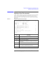
In This Manual
This manual describes the installation and reference information of the
VXIplug&play driver for the Agilent B1500, and consists of the following chapters:
•
Chapter 1, “Installation”
Describes the installation information of the B1500 VXIplug&play driver.
•
Chapter 2, “Driver Functions”
Describes the reference information of the B1500 VXIplug&play driver.
•
Chapter 3, “Programming Examples for Visual Basic Users”
Provides programming examples using the B1500 VXIplug&play driver on
Microsoft Visual Basic environment.
•
Chapter 4, “Programming Examples for C++ Users”
Provides programming examples using the B1500 VXIplug&play driver on
Microsoft Visual C++ environment.
Microsoft, Windows, Visual Basic, and Visual C++ are registered trademarks of Microsoft Corporation. Borland and
C++ Builder are trademarks or registered trademarks of Borland Software Corporation. LabWindows and LabView are
registered trademarks of National Instruments Corporation. All other trademarks are the property of their respective
owners.
Contents
1. Installation
System Requirements. . . . . . . . . . . . . . . . . . . . . . . . . . . . . . . . . . . . . . . . . . . . . . . 1-3
Installing VXIplug&play Driver . . . . . . . . . . . . . . . . . . . . . . . . . . . . . . . . . . . . . . 1-4
Before Programming . . . . . . . . . . . . . . . . . . . . . . . . . . . . . . . . . . . . . . . . . . . . . . . 1-6
2. Driver Functions
Function List . . . . . . . . . . . . . . . . . . . . . . . . . . . . . . . . . . . . . . . . . . . . . . . . . . . . . 2-3
Parameters . . . . . . . . . . . . . . . . . . . . . . . . . . . . . . . . . . . . . . . . . . . . . . . . . . . . . . . 2-8
Status Code. . . . . . . . . . . . . . . . . . . . . . . . . . . . . . . . . . . . . . . . . . . . . . . . . . . . . . 2-14
Function Reference . . . . . . . . . . . . . . . . . . . . . . . . . . . . . . . . . . . . . . . . . . . . . . . 2-16
agb1500_abortMeasure . . . . . . . . . . . . . . . . . . . . . . . . . . . . . . . . . . . . . . . . . . 2-16
agb1500_addSampleSyncIv . . . . . . . . . . . . . . . . . . . . . . . . . . . . . . . . . . . . . . . 2-16
agb1500_asuLed. . . . . . . . . . . . . . . . . . . . . . . . . . . . . . . . . . . . . . . . . . . . . . . . 2-17
agb1500_asuPath . . . . . . . . . . . . . . . . . . . . . . . . . . . . . . . . . . . . . . . . . . . . . . . 2-17
agb1500_asuRange. . . . . . . . . . . . . . . . . . . . . . . . . . . . . . . . . . . . . . . . . . . . . . 2-18
agb1500_autoCal . . . . . . . . . . . . . . . . . . . . . . . . . . . . . . . . . . . . . . . . . . . . . . . 2-18
agb1500_clearCorrData . . . . . . . . . . . . . . . . . . . . . . . . . . . . . . . . . . . . . . . . . . 2-19
agb1500_clearSampleSync. . . . . . . . . . . . . . . . . . . . . . . . . . . . . . . . . . . . . . . . 2-19
agb1500_close . . . . . . . . . . . . . . . . . . . . . . . . . . . . . . . . . . . . . . . . . . . . . . . . . 2-19
agb1500_cmd . . . . . . . . . . . . . . . . . . . . . . . . . . . . . . . . . . . . . . . . . . . . . . . . . . 2-20
agb1500_cmdData_Q . . . . . . . . . . . . . . . . . . . . . . . . . . . . . . . . . . . . . . . . . . . . 2-20
agb1500_cmdInt . . . . . . . . . . . . . . . . . . . . . . . . . . . . . . . . . . . . . . . . . . . . . . . . 2-20
agb1500_cmdInt16Arr_Q. . . . . . . . . . . . . . . . . . . . . . . . . . . . . . . . . . . . . . . . . 2-21
agb1500_cmdInt16_Q . . . . . . . . . . . . . . . . . . . . . . . . . . . . . . . . . . . . . . . . . . . 2-21
agb1500_cmdInt32Arr_Q. . . . . . . . . . . . . . . . . . . . . . . . . . . . . . . . . . . . . . . . . 2-21
agb1500_cmdInt32_Q . . . . . . . . . . . . . . . . . . . . . . . . . . . . . . . . . . . . . . . . . . . 2-22
agb1500_cmdReal . . . . . . . . . . . . . . . . . . . . . . . . . . . . . . . . . . . . . . . . . . . . . . 2-22
agb1500_cmdReal64Arr_Q . . . . . . . . . . . . . . . . . . . . . . . . . . . . . . . . . . . . . . . 2-22
agb1500_cmdReal64_Q . . . . . . . . . . . . . . . . . . . . . . . . . . . . . . . . . . . . . . . . . . 2-23
Agilent B1500 VXIplug&play Driver User’s Guide, Edition 3
Contents
agb1500_cmdString_Q . . . . . . . . . . . . . . . . . . . . . . . . . . . . . . . . . . . . . . . . . .
agb1500_dcl . . . . . . . . . . . . . . . . . . . . . . . . . . . . . . . . . . . . . . . . . . . . . . . . . . .
agb1500_error_message. . . . . . . . . . . . . . . . . . . . . . . . . . . . . . . . . . . . . . . . . .
agb1500_error_query . . . . . . . . . . . . . . . . . . . . . . . . . . . . . . . . . . . . . . . . . . . .
agb1500_errorQueryDetect . . . . . . . . . . . . . . . . . . . . . . . . . . . . . . . . . . . . . . .
agb1500_errorQueryDetect_Q. . . . . . . . . . . . . . . . . . . . . . . . . . . . . . . . . . . . .
agb1500_execCmuAdjust . . . . . . . . . . . . . . . . . . . . . . . . . . . . . . . . . . . . . . . .
agb1500_execLoadCorr . . . . . . . . . . . . . . . . . . . . . . . . . . . . . . . . . . . . . . . . . .
agb1500_execOpenCorr. . . . . . . . . . . . . . . . . . . . . . . . . . . . . . . . . . . . . . . . . .
agb1500_execShortCorr. . . . . . . . . . . . . . . . . . . . . . . . . . . . . . . . . . . . . . . . . .
agb1500_force . . . . . . . . . . . . . . . . . . . . . . . . . . . . . . . . . . . . . . . . . . . . . . . . .
agb1500_forceCmuAcLevel . . . . . . . . . . . . . . . . . . . . . . . . . . . . . . . . . . . . . .
agb1500_forceCmuDcBias . . . . . . . . . . . . . . . . . . . . . . . . . . . . . . . . . . . . . . .
agb1500_init. . . . . . . . . . . . . . . . . . . . . . . . . . . . . . . . . . . . . . . . . . . . . . . . . . .
agb1500_measureBdv . . . . . . . . . . . . . . . . . . . . . . . . . . . . . . . . . . . . . . . . . . .
agb1500_measureIleak. . . . . . . . . . . . . . . . . . . . . . . . . . . . . . . . . . . . . . . . . . .
agb1500_measureM . . . . . . . . . . . . . . . . . . . . . . . . . . . . . . . . . . . . . . . . . . . . .
agb1500_measureP . . . . . . . . . . . . . . . . . . . . . . . . . . . . . . . . . . . . . . . . . . . . .
agb1500_msweepIv . . . . . . . . . . . . . . . . . . . . . . . . . . . . . . . . . . . . . . . . . . . . .
agb1500_msweepMiv . . . . . . . . . . . . . . . . . . . . . . . . . . . . . . . . . . . . . . . . . . .
agb1500_opc_Q . . . . . . . . . . . . . . . . . . . . . . . . . . . . . . . . . . . . . . . . . . . . . . . .
agb1500_readData . . . . . . . . . . . . . . . . . . . . . . . . . . . . . . . . . . . . . . . . . . . . . .
agb1500_readStatusByte_Q. . . . . . . . . . . . . . . . . . . . . . . . . . . . . . . . . . . . . . .
agb1500_recoverOutput. . . . . . . . . . . . . . . . . . . . . . . . . . . . . . . . . . . . . . . . . .
agb1500_reset . . . . . . . . . . . . . . . . . . . . . . . . . . . . . . . . . . . . . . . . . . . . . . . . .
agb1500_resetTimestamp . . . . . . . . . . . . . . . . . . . . . . . . . . . . . . . . . . . . . . . .
agb1500_revision_query . . . . . . . . . . . . . . . . . . . . . . . . . . . . . . . . . . . . . . . . .
agb1500_sampleIv . . . . . . . . . . . . . . . . . . . . . . . . . . . . . . . . . . . . . . . . . . . . . .
agb1500_scuuLed . . . . . . . . . . . . . . . . . . . . . . . . . . . . . . . . . . . . . . . . . . . . . .
agb1500_scuuPath . . . . . . . . . . . . . . . . . . . . . . . . . . . . . . . . . . . . . . . . . . . . . .
agb1500_self_test. . . . . . . . . . . . . . . . . . . . . . . . . . . . . . . . . . . . . . . . . . . . . . .
agb1500_setAdc. . . . . . . . . . . . . . . . . . . . . . . . . . . . . . . . . . . . . . . . . . . . . . . .
2-23
2-24
2-24
2-24
2-25
2-25
2-25
2-26
2-27
2-28
2-28
2-29
2-30
2-30
2-31
2-31
2-32
2-33
2-34
2-36
2-38
2-38
2-39
2-39
2-40
2-40
2-40
2-41
2-43
2-44
2-45
2-46
Agilent B1500 VXIplug&play Driver User’s Guide, Edition 3
Contents
agb1500_setAdcType . . . . . . . . . . . . . . . . . . . . . . . . . . . . . . . . . . . . . . . . . . . . 2-46
agb1500_setBdv . . . . . . . . . . . . . . . . . . . . . . . . . . . . . . . . . . . . . . . . . . . . . . . . 2-47
agb1500_setCmuAdjustMode . . . . . . . . . . . . . . . . . . . . . . . . . . . . . . . . . . . . . 2-48
agb1500_setCmuFreq. . . . . . . . . . . . . . . . . . . . . . . . . . . . . . . . . . . . . . . . . . . . 2-48
agb1500_setCmuInteg . . . . . . . . . . . . . . . . . . . . . . . . . . . . . . . . . . . . . . . . . . . 2-48
agb1500_setCv . . . . . . . . . . . . . . . . . . . . . . . . . . . . . . . . . . . . . . . . . . . . . . . . . 2-49
agb1500_setFilter . . . . . . . . . . . . . . . . . . . . . . . . . . . . . . . . . . . . . . . . . . . . . . . 2-50
agb1500_setIleak . . . . . . . . . . . . . . . . . . . . . . . . . . . . . . . . . . . . . . . . . . . . . . . 2-50
agb1500_setIv. . . . . . . . . . . . . . . . . . . . . . . . . . . . . . . . . . . . . . . . . . . . . . . . . . 2-51
agb1500_setLoadCorrMode . . . . . . . . . . . . . . . . . . . . . . . . . . . . . . . . . . . . . . . 2-52
agb1500_setNthSweep . . . . . . . . . . . . . . . . . . . . . . . . . . . . . . . . . . . . . . . . . . . 2-53
agb1500_setOpenCorrMode. . . . . . . . . . . . . . . . . . . . . . . . . . . . . . . . . . . . . . . 2-54
agb1500_setPbias . . . . . . . . . . . . . . . . . . . . . . . . . . . . . . . . . . . . . . . . . . . . . . . 2-54
agb1500_setPiv. . . . . . . . . . . . . . . . . . . . . . . . . . . . . . . . . . . . . . . . . . . . . . . . . 2-56
agb1500_setSample . . . . . . . . . . . . . . . . . . . . . . . . . . . . . . . . . . . . . . . . . . . . . 2-57
agb1500_setSampleMode. . . . . . . . . . . . . . . . . . . . . . . . . . . . . . . . . . . . . . . . . 2-59
agb1500_setSerRes. . . . . . . . . . . . . . . . . . . . . . . . . . . . . . . . . . . . . . . . . . . . . . 2-60
agb1500_setShortCorrMode. . . . . . . . . . . . . . . . . . . . . . . . . . . . . . . . . . . . . . . 2-60
agb1500_setSweepSync . . . . . . . . . . . . . . . . . . . . . . . . . . . . . . . . . . . . . . . . . . 2-61
agb1500_setSwitch. . . . . . . . . . . . . . . . . . . . . . . . . . . . . . . . . . . . . . . . . . . . . . 2-62
agb1500_spotCmuMeas . . . . . . . . . . . . . . . . . . . . . . . . . . . . . . . . . . . . . . . . . . 2-62
agb1500_spotMeas . . . . . . . . . . . . . . . . . . . . . . . . . . . . . . . . . . . . . . . . . . . . . . 2-64
agb1500_startMeasure . . . . . . . . . . . . . . . . . . . . . . . . . . . . . . . . . . . . . . . . . . . 2-65
agb1500_stopMode . . . . . . . . . . . . . . . . . . . . . . . . . . . . . . . . . . . . . . . . . . . . . 2-67
agb1500_sweepCv . . . . . . . . . . . . . . . . . . . . . . . . . . . . . . . . . . . . . . . . . . . . . . 2-68
agb1500_sweepIv . . . . . . . . . . . . . . . . . . . . . . . . . . . . . . . . . . . . . . . . . . . . . . . 2-70
agb1500_sweepMiv . . . . . . . . . . . . . . . . . . . . . . . . . . . . . . . . . . . . . . . . . . . . . 2-72
agb1500_sweepPbias . . . . . . . . . . . . . . . . . . . . . . . . . . . . . . . . . . . . . . . . . . . . 2-74
agb1500_sweepPiv . . . . . . . . . . . . . . . . . . . . . . . . . . . . . . . . . . . . . . . . . . . . . . 2-76
agb1500_timeOut . . . . . . . . . . . . . . . . . . . . . . . . . . . . . . . . . . . . . . . . . . . . . . . 2-78
agb1500_timeOut_Q . . . . . . . . . . . . . . . . . . . . . . . . . . . . . . . . . . . . . . . . . . . . 2-78
agb1500_zeroOutput . . . . . . . . . . . . . . . . . . . . . . . . . . . . . . . . . . . . . . . . . . . . 2-78
Agilent B1500 VXIplug&play Driver User’s Guide, Edition 3
Contents
3. Programming Examples for Visual Basic Users
Programming Basics . . . . . . . . . . . . . . . . . . . . . . . . . . . . . . . . . . . . . . . . . . . . . . . 3-3
To Create Your Project Template . . . . . . . . . . . . . . . . . . . . . . . . . . . . . . . . . . . . 3-3
To Create Measurement Program. . . . . . . . . . . . . . . . . . . . . . . . . . . . . . . . . . . . 3-6
High Speed Spot Measurement . . . . . . . . . . . . . . . . . . . . . . . . . . . . . . . . . . . . . . . 3-7
Multi Channel Spot Measurement . . . . . . . . . . . . . . . . . . . . . . . . . . . . . . . . . . . . 3-10
Pulsed Spot Measurement . . . . . . . . . . . . . . . . . . . . . . . . . . . . . . . . . . . . . . . . . . 3-14
Staircase Sweep Measurement . . . . . . . . . . . . . . . . . . . . . . . . . . . . . . . . . . . . . . 3-18
Multi Channel Sweep Measurement . . . . . . . . . . . . . . . . . . . . . . . . . . . . . . . . . . 3-34
Pulsed Sweep Measurement . . . . . . . . . . . . . . . . . . . . . . . . . . . . . . . . . . . . . . . . 3-44
Staircase Sweep with Pulsed Bias Measurement. . . . . . . . . . . . . . . . . . . . . . . . . 3-50
Breakdown Voltage Measurement. . . . . . . . . . . . . . . . . . . . . . . . . . . . . . . . . . . . 3-56
Leakage Current Measurement . . . . . . . . . . . . . . . . . . . . . . . . . . . . . . . . . . . . . . 3-59
4. Programming Examples for C++ Users
Programming Basics . . . . . . . . . . . . . . . . . . . . . . . . . . . . . . . . . . . . . . . . . . . . . . . 4-3
To Create Your Project Template . . . . . . . . . . . . . . . . . . . . . . . . . . . . . . . . . . . . 4-3
To Create Measurement Program. . . . . . . . . . . . . . . . . . . . . . . . . . . . . . . . . . . . 4-6
High Speed Spot Measurement . . . . . . . . . . . . . . . . . . . . . . . . . . . . . . . . . . . . . . . 4-7
Multi Channel Spot Measurement . . . . . . . . . . . . . . . . . . . . . . . . . . . . . . . . . . . . . 4-9
Pulsed Spot Measurement . . . . . . . . . . . . . . . . . . . . . . . . . . . . . . . . . . . . . . . . . . 4-11
Staircase Sweep Measurement . . . . . . . . . . . . . . . . . . . . . . . . . . . . . . . . . . . . . . 4-13
Multi Channel Sweep Measurement . . . . . . . . . . . . . . . . . . . . . . . . . . . . . . . . . . 4-23
Pulsed Sweep Measurement . . . . . . . . . . . . . . . . . . . . . . . . . . . . . . . . . . . . . . . . 4-29
Staircase Sweep with Pulsed Bias Measurement. . . . . . . . . . . . . . . . . . . . . . . . . 4-33
Agilent B1500 VXIplug&play Driver User’s Guide, Edition 3
Contents
Breakdown Voltage Measurement . . . . . . . . . . . . . . . . . . . . . . . . . . . . . . . . . . . . 4-37
Leakage Current Measurement . . . . . . . . . . . . . . . . . . . . . . . . . . . . . . . . . . . . . . 4-39
Sampling Measurement . . . . . . . . . . . . . . . . . . . . . . . . . . . . . . . . . . . . . . . . . . . . 4-41
High Speed Spot C Measurement . . . . . . . . . . . . . . . . . . . . . . . . . . . . . . . . . . . . 4-45
CV Sweep Measurement . . . . . . . . . . . . . . . . . . . . . . . . . . . . . . . . . . . . . . . . . . . 4-49
Agilent B1500 VXIplug&play Driver User’s Guide, Edition 3
Contents
Agilent B1500 VXIplug&play Driver User’s Guide, Edition 3
1
Installation
Installation
This chapter describes the system requirements and installation procedure for the
Agilent B1500 VXIplug&play driver.
•
“System Requirements”
•
“Installing VXIplug&play Driver”
•
“Before Programming”
1-2
Agilent B1500 VXIplug&play Driver User’s Guide, Edition 3
Installation
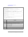
System Requirements
The following system environments are required.
•
Operating System
Microsoft Windows 7 Professional or Windows XP Professional. It must be
supported by the application development environment.
•
Application Development Environment (programming environment)
Microsoft Visual Basic, Microsoft Visual C++, Borland C++Builder, National
Instruments LabWindows/CVI or LabView, or Agilent VEE.
•
GPIB (IEEE 488) Interface and VISA I/O Library
Agilent GPIB interface with Agilent IO libraries or equivalent.
•
Computer and peripherals
Required specifications depend on the application development environment.
See manual of the software.
•
Minimum disk space
2 MB for the Agilent B1500 VXIplug&play driver
NOTE
For the latest system requirements, go to www.agilent.com and type in B1500A in
the Search field at the top of the page.
Agilent B1500 VXIplug&play Driver User’s Guide, Edition 3
1-3
Installation
Installing VXIplug&play Driver
The installation flow is shown below. If you have already installed the GPIB (IEEE
488) interface, VISA I/O library, and programming software on your computer, skip
steps 1 through 4.
1. Install the GPIB interface to your PC.
See manual of the GPIB interface. Note the model number of the GPIB
interface, as you may need it to configure the interface (in step 3).
2. Install VISA I/O library.
Follow the setup program instructions.
3. Configure and check the GPIB interface.
See manual of the VISA I/O library.
4. Install the programming software.
Follow the setup program instructions.
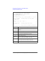
5. Install the Agilent B1500 VXIplug&play driver.
a. Insert the Agilent B1500 Software CD-ROM to the drive connected to your
computer.
b. Execute setup.exe or \Pnp\B1500.exe on the CD-ROM.
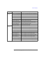
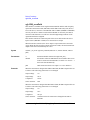
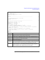
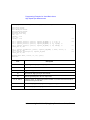
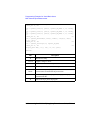
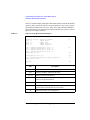
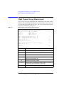
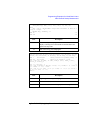
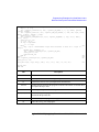
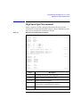
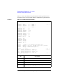
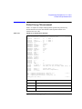
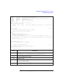
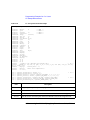
The setup program installs the driver. See Table 1-1 for the installed files.
1-4
Agilent B1500 VXIplug&play Driver User’s Guide, Edition 3
Installation
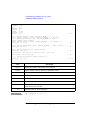
Table 1-1
Agilent B1500 VXIplug&play Driver Files
File Name a
Description
<install folder>\Winnt\Agb1500\agb1500.bas
Driver for Microsoft Visual Basic
<install folder>\Winnt\Agb1500\agb1500.c
Driver source code file
<install folder>\Winnt\Agb1500\agb1500.def
DLL export definition file
<install folder>\Winnt\Agb1500\agb1500.fp
Front panel file
<install folder>\Winnt\Agb1500\agb1500.h
Driver header file
<install folder>\Winnt\Agb1500\agb1500.hlp
On-line help file
<install folder>\Winnt\Agb1500\readme.txt
Read me file
<install folder>\Winnt\bin\agb1500_32.dll
Driver DLL file
<install folder>\Winnt\include\agb1500.h
Driver header file
<install folder>\Winnt\lib\bc\agb1500.lib
Library for Borland C++Builder
<install folder>\Winnt\lib\bc\agb1500_32.lib
Library for Borland C++Builder
<install folder>\Winnt\lib\msc\agb1500.lib
Library for Microsoft C++
<install folder>\Winnt\lib\msc\agb1500_32.lib
Library for Microsoft C++
a. Execute echo %VXIPNPPATH% on the Command Prompt to know <install folder>.
Agilent B1500 VXIplug&play Driver User’s Guide, Edition 3
1-5
Installation
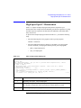
Before Programming
Before starting the programming using the Agilent B1500 VXIplug&play driver,
perform following.
1. Terminate the Agilent EasyEXPERT software as follows.
a. Select File > Exit on the EasyEXPERT main window.
b. Click [x] at the upper right corner of the Start EasyEXPERT button.
2. Open the Agilent Connection Expert window by clicking Agilent IO Control
icon on the Windows task bar and selecting Agilent Connection Expert.
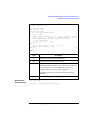
3. Change the following setup items as shown below. The setup window can be
opened by highlighting GPIB0 in the Instrument I/O on this PC area, and
clicking Change Properties... button.
GPIB address
B1500A’s GPIB address (ex: 17)
System Controller
No
Auto-discover
No
The factory shipment initial values are 17, No, and No, respectively.
4. If the Reboot Required dialog box is displayed, reboot the B1500A by clicking
the Reboot Now button.
If the Reboot Required dialog box is not displayed, open the Start EasyEXPERT
button by selecting the Start EasyEXPERT menu in the Windows start menu.
NOTE
Start EasyEXPERT Button
Leave the Start EasyEXPERT button on the B1500A screen. The button must be
displayed on the screen or minimized to the Windows task bar. The Start
EasyEXPERT service must be run to control the Agilent B1500A from an external
computer.
1-6
Agilent B1500 VXIplug&play Driver User’s Guide, Edition 3
2
Driver Functions
Driver Functions
This chapter is the complete reference of VXIplug&play driver for the Agilent
B1500.
NOTE
•
“Function List”
•
“Parameters”
•
“Status Code”
•
“Function Reference”
Additional information
See the on-line help of the VXIplug&play drivers, or open the Agb1500.hlp file in
the directory that the driver is installed. See “Installing VXIplug&play Driver” on
page 1-4.
For measurement functions of the Agilent B1500, see Agilent B1500 Programming
Guide.
2-2
Agilent B1500 VXIplug&play Driver User’s Guide, Edition 3
Driver Functions
Function List
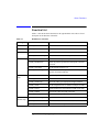
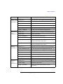
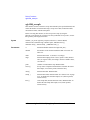
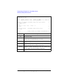
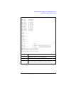
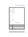
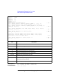
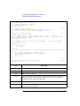
Table 2-1 lists all the driver functions for the Agilent B1500. You will see a brief
description of the functions in the table.
Table 2-1
Category
B1500 Driver Functions
Function
Description
Initialize
agb1500_init
Initializes the software connection with the B1500.
Close
agb1500_close
Closes the software connection with the B1500.
Miscellaneous
agb1500_autoCal
Sets the auto calibration mode
agb1500_resetTimestamp
Clears the timer count (time stamp data).
agb1500_setSwitch
Sets the channel output switch.
agb1500_abortMeasure
Aborts the present operation and subsequent command
execution.
agb1500_zeroOutput
Sets the channel output to 0 V.
agb1500_recoverOutput
Recovers the channel output that is set to 0 V by the
agb1500_zeroOutput function.
agb1500_setFilter
Sets the output filter.
agb1500_setSerRes
Sets the series resistor.
agb1500_setAdcType
Selects the ADC type, high speed or high resolution.
agb1500_setAdc
Sets the integration time or number of samples for ADC.
agb1500_asuLed
Enables/disables the status indicator (LED) of the ASU.
agb1500_asuPath
Controls the connection path of the ASU.
agb1500_asuRange
Enables/disables 1 pA operation of the ASU.
agb1500_setCmuInteg
Sets the A/D converter of the MFCMU.
agb1500_scuuLed
Enables/disables the status indicator (LED) of the SCUU.
agb1500_scuuPath
Controls the connection path of the SCUU.
Channel setup
SMU channel
setup
MFCMU
channel setup
Agilent B1500 VXIplug&play Driver User’s Guide, Edition 3
2-3
Driver Functions
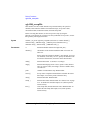
Category
Spot
measurement
Spot C
measurement
Pulsed spot
measurement
Function
Description
agb1500_force
Applies DC current or voltage from the specified SMU.
agb1500_spotMeas
Performs high speed spot measurement.
agb1500_measureM
Performs spot measurement by multiple channels.
agb1500_force
Applies DC current or voltage from the specified SMU.
agb1500_setCmuFreq
Sets the MFCMU measurement frequency.
agb1500_forceCmuAcLevel
Applies AC voltage from the MFCMU.
agb1500_forceCmuDcBias
Applies DC bias from the MFCMU.
agb1500_spotCmuMeas
Performs high speed spot C measurement.
agb1500_force
Applies DC current or voltage from the specified SMU.
agb1500_setPbias
Sets the pulsed bias source.
agb1500_measureP
Performs pulsed spot measurement.
Staircase sweep agb1500_force
measurement
agb1500_setIv
Pulsed sweep
measurement
Applies DC current or voltage from the specified SMU.
Sets the sweep source.
agb1500_setSweepSync
Sets the synchronous sweep source.
agb1500_stopMode
Sets automatic sweep abort and post sweep output.
agb1500_sweepIv
Performs sweep measurement by one channel.
agb1500_sweepMiv
Performs sweep measurement by multiple channels.
agb1500_force
Applies DC current or voltage from the specified SMU.
agb1500_setPiv
Sets the pulsed sweep source.
agb1500_setSweepSync
Sets the synchronous sweep source.
agb1500_stopMode
Sets automatic sweep abort.
agb1500_sweepPiv
Performs pulsed sweep measurement.
2-4
Agilent B1500 VXIplug&play Driver User’s Guide, Edition 3
Driver Functions
Category
Function
Staircase sweep agb1500_force
with pulsed bias
agb1500_setIv
measurement
agb1500_setPbias
Multi channel
sweep
measurement
Sampling
measurement
Breakdown
voltage
measurement
Description
Applies DC current or voltage from the specified SMU.
Sets the sweep source.
Sets the pulsed bias source.
agb1500_setSweepSync
Sets the synchronous sweep source.
agb1500_stopMode
Sets automatic sweep abort and post sweep output.
agb1500_sweepPbias
Performs sweep measurement with pulsed bias.
agb1500_force
Applies DC current or voltage from the specified SMU.
agb1500_setIv
Sets the sweep source.
agb1500_setNthSweep
Sets the synchronous sweep source.
agb1500_stopMode
Sets automatic sweep abort and post sweep output.
agb1500_msweepIv
Performs sweep measurement by one measurement
channel with multiple sweep sources.
agb1500_msweepMiv
Performs sweep measurement by multiple measurement
channels with multiple sweep sources.
agb1500_force
Applies DC current or voltage from the specified SMU.
agb1500_addSampleSyncIv
Sets source channel for the sampling measurement.
agb1500_setSampleMode
Sets sampling mode, linear or logarithm.
agb1500_setSample
Sets sampling timing parameters.
agb1500_stopMode
Sets automatic abort and post measurement output.
agb1500_sampleIv
Performs sampling measurement.
agb1500_clearSampleSync
Clears the source channels for the sampling measurement.
agb1500_force
Applies DC current or voltage from the specified SMU.
agb1500_setBdv
Sets the quasi pulse source.
agb1500_measureBdv
Performs quasi pulsed spot breakdown voltage
measurement.
Agilent B1500 VXIplug&play Driver User’s Guide, Edition 3
2-5
Driver Functions
Category
Function
Description
Leakage current agb1500_force
measurement
agb1500_setIleak
Applies DC current or voltage from the specified SMU.
Sets the quasi pulse source.
agb1500_measureIleak
Performs quasi pulsed spot leakage current measurement.
agb1500_force
Applies DC current or voltage from the specified SMU.
agb1500_setCmuFreq
Sets the MFCMU measurement frequency.
agb1500_forceCmuAcLevel
Applies AC voltage from the MFCMU.
agb1500_setCv
Sets the DC bias sweep source.
agb1500_stopMode
Sets automatic sweep abort and post sweep output.
agb1500_sweepCv
Performs CV sweep measurement.
Primitive
Measurement
Functions
agb1500_startMeasure
Specifies measurement mode, and performs measurement.
agb1500_readData
Reads and returns the source setup data or the data
measured by the agb1500_startMeasure function.
Utility
agb1500_reset
Executes the B1500 reset.
agb1500_self_test
Executes the B1500 self-test.
agb1500_error_query
Queries the B1500 for error code/message.
agb1500_error_message
Queries for the driver errors.
agb1500_revision_query
Queries for the B1500 firmware/driver revisions.
agb1500_timeOut
Sets the timeout.
agb1500_timeOut_Q
Queries for the timeout setting.
agb1500_errorQueryDetect
Sets the automatic error checking.
CV sweep
measurement
agb1500_errorQueryDetect_Q Queries for the automatic error checking setting.
agb1500_dcl
Sends the Device Clear.
agb1500_readStatusByte_Q
Reads the B1500 status byte.
agb1500_opc_Q
Checks the B1500 operation completion status.
2-6
Agilent B1500 VXIplug&play Driver User’s Guide, Edition 3
Driver Functions
Category
MFCMU data
correction
Passthrough
Functions
Function
Description
agb1500_setCmuAdjustMode Selects the correction data setup mode for the MFCMU.
agb1500_execCmuAdjust
Gets the correction data for the MFCMU.
agb1500_setLoadCorrMode
Sets the CMU load correction function ON or OFF.
agb1500_execLoadCorr
Performs the CMU load correction
agb1500_setOpenCorrMode
Sets the CMU open correction function ON or OFF.
agb1500_execOpenCorr
Performs the CMU open correction
agb1500_setShortCorrMode
Sets the CMU short correction function ON or OFF.
agb1500_execShortCorr
Performs the CMU short correction
agb1500_clearCorrData
Clears the CMU correction data.
agb1500_cmd
Sends a command.
agb1500_cmdInt
Sends a command with an integer parameter.
agb1500_cmdReal
Sends a command with a real parameter.
agb1500_cmdData_Q
Sends a command to read any data.
agb1500_cmdString_Q
Sends a command to read string response.
agb1500_cmdInt16_Q
Sends a command to read 16 bit integer response.
agb1500_cmdInt16Arr_Q
Sends a command to read 16 bit integer array response.
agb1500_cmdInt32_Q
Sends a command to read 32 bit integer response.
agb1500_cmdInt32Arr_Q
Sends a command to read 32 bit integer array response.
agb1500_cmdReal64_Q
Sends a command to read 64 bit real response.
agb1500_cmdReal64Arr_Q
Sends a command to read 64 bit real array response.
Agilent B1500 VXIplug&play Driver User’s Guide, Edition 3
2-7
Driver Functions
Parameters
The parameters used by several functions are explained in this section.
•
“channel value”
•
“SMU range value and ranging mode”
•
“SMU output voltage, resolution, and compliance by range”
•
“SMU output current, resolution, and compliance by range”
•
“MFCMU measurement parameters”
•
“MFCMU measurement range”
In this section, the parameters are put in italics such as channel.
NOTE
Macros
Some functions can use macros to set the parameter values. For details of functions
and macros, refer to the help file (agb1500.hlp) in the directory that the driver is
installed.
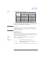
Table 2-2
channel value
Available module and slot number a
channel
1, 2, 3, 4, 5, 6, 7,
8, 9, or 10
MPSMU installed in the slot channel.
HPSMUb installed in the slots channel and channel+1.
HRSMU installed in the slot channel.
ASU connected to the HRSMU in the slot channel.
MFCMU installed in the slot channel.
SCUU connected to the MFCMU in the slot channel.
a. Slot number 1 to 10 have been assigned to the bottom slot to the top slot
respectively.
b. HPSMU occupies two slots.
2-8
Agilent B1500 VXIplug&play Driver User’s Guide, Edition 3
Driver Functions
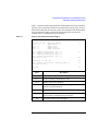
Table 2-3
SMU range value and ranging mode
Available range values a b
Ranging mode used for
output/measurement
range = 0
Auto ranging
0 < |range| ≤ 0.5 V
0.5 V limited auto ranging
0.5 < |range| ≤ 2 V
2 V limited auto ranging
2 V < |range| ≤ 5 V
5 V limited auto ranging
5 V < |range| ≤ 20 V
20 V limited auto ranging
20 V < |range| ≤ 40 V
40 V limited auto ranging
40 V < |range| ≤ 100 V
100 V limited auto ranging
100 V < |range| ≤ 200 V
200 V limited auto ranging
for HPSMU, voltage
0 < |range| ≤ 1 pA
1 pA limited auto ranging
for HRSMU with ASU, current
1 pA < |range| ≤ 10 pA
10 pA limited auto ranging
0 < |range| ≤ 10 pA
10 pA limited auto ranging
10 pA < |range| ≤ 100 pA
100 pA limited auto ranging
100 pA < |range| ≤ 1 nA
1 nA limited auto ranging
1 nA < |range| ≤ 10 nA
10 nA limited auto ranging
10 nA < |range| ≤ 100 nA
100 nA limited auto ranging
100 nA < |range| ≤ 1 μA
1 μA limited auto ranging
1 μA < |range| ≤ 10 μA
10 μA limited auto ranging
10 μA < |range| ≤ 100 μA
100 μA limited auto ranging
100 μA < |range| ≤ 1 mA
1 mA limited auto ranging
1 mA < |range| ≤ 10 mA
10 mA limited auto ranging
10 mA < |range| ≤ 100 mA
100 mA limited auto ranging
100 mA < |range| ≤ 1 A
1 A limited auto ranging
Remarks
for MP/HRSMU, voltage
for MP/HRSMU, voltage
for HRSMU, current
for HPSMU, current
a. For the functions to start or execute measurement, negative range values are available. The negative values set the ranging mode to the fix, not the limited auto.
b. For the functions to start or execute the measurement that uses the pulse source, set 0 or positive
value to set the minimum range that covers the compliance value automatically.
Agilent B1500 VXIplug&play Driver User’s Guide, Edition 3
2-9
Driver Functions
NOTE
Auto ranging mode
SMU uses the optimum range to force/measure voltage or current.
NOTE
Limited auto ranging mode
SMU uses the optimum range to force/measure voltage or current. Then, the SMU
never uses the range less than the specified range.
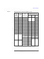
Table 2-4
SMU output voltage, resolution, and compliance by range
Output
range
(actually
used)
Setting
resolution
in V
0.5 V
25E-6
2V
Output
voltage a in V
Maximum comp value b in A
HPSMU
MPSMU
HRSMU
0 to ± 0.5
NA
±100E-3
±100E-3
100E-6
0 to ± 2
±1
±100E-3
±100E-3
5V
250E-6
0 to ± 5
NA
±100E-3
±100E-3
20 V
1E-3
0 to ± 20
±1
±100E-3
±100E-3
40 V
2E-3
0 to ± 20
±500E-3
±100E-3
±100E-3
±50E-3
±50E-3
±100E-3
±100E-3
to ± 40
±50E-3
±50E-3
to ± 100
±20E-3
±20E-3
NA
NA
to ± 40
100 V
200 V
5E-3
10E-3
0 to ± 20
0 to ± 200
±125E-3
±50E-3
a. Parameter name may be base, bias, peak, value, start, stop, and so on.
b. This column shows the maximum value of the current compliance.
2-10
Agilent B1500 VXIplug&play Driver User’s Guide, Edition 3
Driver Functions
Table 2-5
SMU output current, resolution, and compliance by range
Output
range
(actually
used)
Setting
resolution
in A
Output
current a in A
1 pA
1E-15
0 to ± 1.15 E-12
10 pA
5E-15
0 to ± 11.5 E-12
±100
100 pA
5E-15
0 to ± 115 E-12
±100
1 nA
50E-15
0 to ± 1.15 E-9
±200
±100
±100
10 nA
500E-15
0 to ± 11.5 E-9
±200
±100
±100
100 nA
5E-12
0 to ± 115 E-9
±200
±100
±100
1 μA
50E-12
0 to ± 1.15E-6
±200
±100
±100
10 μA
500E-12
0 to ± 11.5E-6
±200
±100
±100
100 μA
5E-9
0 to ± 115E-6
±200
±100
±100
1 mA
50E-9
0 to ± 1.15E-3
±200
±100
±100
10 mA
500E-9
0 to ± 11.5E-3
±200
±100
±100
100 mA
5E-6
0 to ± 20E-3
±200
±100
±100
to ± 50E-3
±200
±40
±40
to ± 100E-3
±100
±20
±20
to ± 115E-3
±100
NA
NA
0 to ± 50E-3
±200
to ± 125E-3
±100
to ± 500E-3
±40
to ± 1
±20
1A
50E-6
Maximum comp value b in V
HPSMU
MPSMU
HRSMU
NA
NA
±100
a. Parameter name may be base, bias, peak, value, start, stop, and so on.
b. This column shows the maximum value of the voltage compliance.
Agilent B1500 VXIplug&play Driver User’s Guide, Edition 3
2-11
Driver Functions
Table 2-6
MFCMU measurement parameters
mode
2-12
Primary Parameter
Secondary Parameter
1
R (resistance, Ω)
X (reactance, Ω)
2
G (conductance, S)
B (susceptance, S)
10
Z (impedance, Ω)
θ (phase, radian)
11
Z (impedance, Ω)
θ (phase, degree)
20
Y (admittance, S)
θ (phase, radian)
21
Y (admittance, S)
θ (phase, degree)
100
Cp (parallel capacitance, F)
G (conductance, S)
101
Cp (parallel capacitance, F)
D (dissipation factor)
102
Cp (parallel capacitance, F)
Q (quality factor)
103
Cp (parallel capacitance, F)
Rp (parallel resistance, Ω)
200
Cs (series capacitance, F)
Rs (series resistance, Ω)
201
Cs (series capacitance, F)
D (dissipation factor)
202
Cs (series capacitance, F)
Q (quality factor)
300
Lp (parallel inductance, H)
G (conductance, S)
301
Lp (parallel inductance, H)
D (dissipation factor)
302
Lp (parallel inductance, H)
Q (quality factor)
303
Lp (parallel inductance, H)
Rp (parallel resistance, Ω)
400
Ls (series inductance, H)
Rs (series resistance, Ω)
401
Ls (series inductance, H)
D (dissipation factor)
402
Ls (series inductance, H)
Q (quality factor)
Agilent B1500 VXIplug&play Driver User’s Guide, Edition 3
Driver Functions
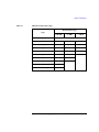
Table 2-7
MFCMU measurement range
Measurement range a
range
≤ 200 kHz
range = 0
≤ 2 MHz
≤ 5 MHz
auto ranging
0 < range < 100
50 Ω
50 Ω
50 Ω
100 ≤ range < 300
100 Ω
100 Ω
100 Ω
300 ≤ range < 1000
300 Ω
300 Ω
300 Ω
1000 ≤ range < 3000
1 kΩ
1 kΩ
1 kΩ
3000 ≤ range < 10000
3 kΩ
3 kΩ
3 kΩ
10000 ≤ range < 30000
10 kΩ
10 kΩ
30000 ≤ range < 100000
30 kΩ
30 kΩ
100000 ≤ range < 300000
100 kΩ
300000 ≤ range
300 kΩ
a. Available measurement ranges depend on the measurement frequency.
Agilent B1500 VXIplug&play Driver User’s Guide, Edition 3
2-13
Driver Functions
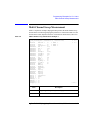
Status Code
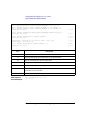
After measurement is performed, the Agilent B1500 returns a status code to notify
you if the measurement has been completed successfully. The status code will be
returned with the measurement data by the following functions that perform
measurement. Available status values are listed in Table 2-8.
NOTE
•
“agb1500_spotCmuMeas”
•
“agb1500_spotMeas”
•
“agb1500_measureM”
•
“agb1500_measureP”
•
“agb1500_sampleIv”
•
“agb1500_sweepCv”
•
“agb1500_sweepIv”
•
“agb1500_sweepMiv”
•
“agb1500_msweepIv”
•
“agb1500_msweepMiv”
•
“agb1500_sweepPiv”
•
“agb1500_sweepPbias”
•
“agb1500_measureBdv”
•
“agb1500_measureIleak”
•
“agb1500_readData”
If multiple status conditions were found
Sum of the status values will be returned. For example, if an A/D converter
overflow occurred, and an SMU was oscillating during the measurements, the
returned value is 3 (=1+2).
2-14
Agilent B1500 VXIplug&play Driver User’s Guide, Edition 3
Driver Functions
Table 2-8
Status Values
Value
Bit
0
-
1
1
(LSB)
2
2
Description
No error.
A/D converter overflowed.
One or more channels are oscillating. For SMU.
MFCMU is in the NULL loop unbalance condition.
4
3
Another channel reached its compliance setting. For SMU.
MFCMU is in the IV amplifier saturation condition.
8
4
This channel reached its compliance setting.
Normal post-measurement state by agb1500_measureBdv.
16
5
Target value was not found within the search range.
(for agb1500_readData)
Detection time was too long.
(for agb1500_measureBdv and agb1500_measureIleak)
32
6
Search measurement was automatically stopped.
(for agb1500_readData)
Output slew rate was too late.
(for agb1500_measureBdv and agb1500_measureIleak)
Agilent B1500 VXIplug&play Driver User’s Guide, Edition 3
2-15
Driver Functions
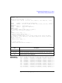
agb1500_abortMeasure
Function Reference
This section describes the functions of VXIplug&play driver for the Agilent B1500.
The functions are appeared in alphabetical order.
agb1500_abortMeasure
This function aborts the B1500’s present operation, such as the measurement
executed by the agb1500_startMeasure function, the dc bias output by the
agb1500_force function, and so on.
Syntax
ViStatus _VI_FUNC agb1500_abortMeasure(ViSession vi);
Parameters
vi
Instrument handle returned from agb1500_init( ).
agb1500_addSampleSyncIv
This function specifies the constant voltage/current source for the sampling
measurements, and sets the parameters.
Syntax
ViStatus _VI_FUNC agb1500_addSampleSyncIv(ViSession vi, ViInt32 channel,
ViInt32 mode, ViReal64 range, ViReal64 base, ViReal64 bias, ViReal64 comp);
Parameters
vi
Instrument handle returned from agb1500_init( ).
channel
Slot number of the slot that installs the SMU to be used. See
Table 2-2.
mode
Source output mode. 1 (current) or 2 (voltage).
range
Output ranging mode. 0 (auto) or positive value (limited auto).
base
Source output value during hold time (in A or V).
bias
Source output value in the sampling measurement (in A or V).
comp
Compliance value (in V or A). It must be voltage for the current
source, or current for the voltage source.
NOTE
range, base, bias, comp parameters
Available values depend on the unit. See “Parameters” on page 2-8.
2-16
Agilent B1500 VXIplug&play Driver User’s Guide, Edition 3
Driver Functions
agb1500_asuLed
agb1500_asuLed
This function is available for the Agilent B1500 installed with the high resolution
SMU (HRSMU) and the atto sense and switch unit (ASU).
Disables or enables the connection status indicator (LED) of the ASU. This function
is effective for the specified channel.
Syntax
ViStatus _VI_FUNC agb1500_asuLed(ViSession vi, ViInt32 channel,
ViInt32 mode);
Parameters
vi
Instrument handle returned from agb1500_init( ).
channel
Slot number where the HRSMU has been installed. The ASU
must be connected to the HRSMU. See Table 2-2.
mode
0: Disables the indicator.
1: Enables the indicator. Default setting.
agb1500_asuPath
This function is available for the Agilent B1500 installed with the high resolution
SMU (HRSMU) and the atto sense and switch unit (ASU). This function is not
effective when the High Voltage indicator of the Agilent B1500 has been lighted.
Controls the connection path of the ASU. Switches the ASU input resource
(HRSMU or the instrument connected to the AUX input) to be connected to the
ASU output. This function is effective for the specified channel.
When the Agilent B1500 is turned on, the ASU output will be connected to the
SMU connector side, but the HRSMU will not be enabled yet. After this function is
executed with path=2, the HRSMU specified by channel cannot be used. After this
function is executed with path=1, the HRSMU output will appear on the ASU
output. Then the HRSMU output will be 0 V.
Syntax
ViStatus _VI_FUNC agb1500_asuPath(ViSession vi, ViInt32 channel,
ViInt32 path);
Parameters
vi
Instrument handle returned from agb1500_init( ).
channel
Slot number where the HRSMU has been installed. The ASU
must be connected to the HRSMU. See Table 2-2.
Agilent B1500 VXIplug&play Driver User’s Guide, Edition 3
2-17
Driver Functions
agb1500_asuRange
path
NOTE
Path connected to the ASU output. 1 (the ASU output will be
connected to the SMU connector side) or 2 (the ASU output
will be connected to the AUX connector side).
To use ASU
To use the ASU, connect it to the correct HRSMU properly before turning the
Agilent B1500A on. For the connection, see User’s Guide.
The ASU will add the connection switch function described above to the B1500A
and the 1 pA measurement range to the HRSMU. Use the agb1500_asuRange
function to enable/disable the 1 pA range for the auto ranging operation.
Remember that the series resistor in the HRSMU connected to the ASU cannot be
used.
agb1500_asuRange
This function is available for the Agilent B1500 installed with the high resolution
SMU (HRSMU) and the atto sense and switch unit (ASU).
Enables or disables the 1 pA range for the auto ranging operation.
Syntax
ViStatus _VI_FUNC agb1500_asuRange(ViSession vi, ViInt32 channel,
ViInt32 mode);
Parameters
vi
Instrument handle returned from agb1500_init( ).
channel
Slot number where the HRSMU has been installed. The ASU
must be connected to the HRSMU. See Table 2-2.
mode
0: Enables 1 pA range.
1: Disables 1 pA range.
agb1500_autoCal
This function enables or disables the auto calibration function.
Syntax
ViStatus _VI_FUNC agb1500_autoCal(ViSession vi, ViInt32 state);
Parameters
vi
Instrument handle returned from agb1500_init( ).
state
Auto calibration mode. 0 (off) or 1 (on).
2-18
Agilent B1500 VXIplug&play Driver User’s Guide, Edition 3
Driver Functions
agb1500_clearCorrData
agb1500_clearCorrData
This function clears the CMU open/short/load correction data.
Syntax
ViStatus _VI_FUNC agb1500_clearCorrData(ViSession vi, ViInt32 channel,
ViInt32 mode);
Parameters
vi
Instrument handle returned from agb1500_init( ).
channel
Slot number of the slot that installs the MFCMU to be used. See
Table 2-2. channel=-1 detects the slot automatically.
mode
0: Resets frequency settings after clearing the correction data.
1: Keeps the settings after clearing the correction data.
If mode=0, the default measurement frequencies are set to the
CMU. The default frequencies are 1 k, 2 k, 5 k, 10 k, 20 k, 50 k,
100 k, 200 k, 500 k, 1 M, 2 M, and 5 MHz.
agb1500_clearSampleSync
This function clears the channel setup defined by the agb1500_addSampleSyncIv
function.
Syntax
ViStatus _VI_FUNC agb1500_clearSampleSync(ViSession vi);
Parameters
vi
Instrument handle returned from agb1500_init( ).
agb1500_close
This function terminates the software connection to the instrument and deallocates
system resources. It is generally a good programming habit to close the instrument
handle when the program is done using the instrument.
Syntax
ViStatus _VI_FUNC agb1500_close(ViSession vi);
Parameters
vi
Instrument handle returned from agb1500_init( ).
Agilent B1500 VXIplug&play Driver User’s Guide, Edition 3
2-19
Driver Functions
agb1500_cmd
agb1500_cmd
This function passes the cmd_str string to the instrument. Must be a NULL
terminated C string.
Syntax
ViStatus _VI_FUNC agb1500_cmd(ViSession vi, ViString cmd_str);
Parameters
vi
Instrument handle returned from agb1500_init( ).
cmd_str
Instrument command (cannot exceed 256 bytes in length).
Example
ViSession vi;
ViStatus ret;
ret = agb1500_cmd(vi, "AB");
/* sends the AB command */
agb1500_cmdData_Q
This function passes the cmd_str string to the instrument. This entry point will wait
for a response which may be any data. You specify the cmd_str and size parameters,
and get result[ ].
Syntax
ViStatus _VI_FUNC agb1500_cmdData_Q(ViSession vi, ViString cmd_str,
ViInt32 size, ViChar _VI_FAR result[ ] );
Parameters
vi
Instrument handle returned from agb1500_init( ).
cmd_str
Instrument command (cannot exceed 256 bytes in length).
size
Length of result in bytes. 2 to 32767.
result[ ]
Response from instrument.
agb1500_cmdInt
This function passes the cmd_str string to the instrument. This entry point passes the
string in cmd_str followed by a space and then the integer in value. Note that either
an Int16 or 32 can be passed as the Int16 will be promoted.
Syntax
ViStatus _VI_FUNC agb1500_cmdInt(ViSession vi, ViString cmd_str,
ViInt32 value);
Parameters
vi
Instrument handle returned from agb1500_init( ).
cmd_str
Instrument command (cannot exceed 256 bytes in length).
2-20
Agilent B1500 VXIplug&play Driver User’s Guide, Edition 3
Driver Functions
agb1500_cmdInt16Arr_Q
value
Parameter for command. -2147483647 to 2147483647.
agb1500_cmdInt16Arr_Q
This function passes the cmd_str string to the instrument. This function expects a
response that is a definite arbitrary block of 16 bit integers. You specify the cmd_str
and size parameters, and get result[ ] and count.
Syntax
ViStatus _VI_FUNC agb1500_cmdInt16Arr_Q(ViSession vi, ViString cmd_str,
ViInt32 size, ViInt16 _VI_FAR result[ ], ViPInt32 count);
Parameters
vi
Instrument handle returned from agb1500_init( ).
cmd_str
Instrument command (cannot exceed 256 bytes in length).
size
Size of result[ ] (number of items in the array).
1 to 2147483647.
result[ ]
Response from instrument.
count
Count of valid items in result[ ]. Returned data.
agb1500_cmdInt16_Q
This function passes the cmd_str string to the instrument. This function expects a
response that can be returned as a 16 bit integer.
Syntax
ViStatus _VI_FUNC agb1500_cmdInt16_Q(ViSession vi, ViString cmd_str,
ViPInt16 result);
Parameters
vi
Instrument handle returned from agb1500_init( ).
cmd_str
Instrument command (cannot exceed 256 bytes in length).
result
Response from instrument.
agb1500_cmdInt32Arr_Q
This function passes the cmd_str string to the instrument. This function expects a
response that is a definite arbitrary block of 32 bit integers. You specify the cmd_str
and size parameters, and get result[ ] and count.
Syntax
ViStatus _VI_FUNC agb1500_cmdInt32Arr_Q(ViSession vi, ViString cmd_str,
ViInt32 size, ViInt32 _VI_FAR result[ ], ViPInt32 count);
Agilent B1500 VXIplug&play Driver User’s Guide, Edition 3
2-21
Driver Functions
agb1500_cmdInt32_Q
Parameters
vi
Instrument handle returned from agb1500_init( ).
cmd_str
Instrument command (cannot exceed 256 bytes in length).
size
Size of result[ ] (number of items in the array).
1 to 2147483647.
result[ ]
Response from instrument.
count
Count of valid items in result[ ]. Returned data.
agb1500_cmdInt32_Q
This function passes the cmd_str string to the instrument. This function expects a
response that can be returned as a 32 bit integer.
Syntax
ViStatus _VI_FUNC agb1500_cmdInt32_Q(ViSession vi, ViString cmd_str,
ViPInt32 result);
Parameters
vi
Instrument handle returned from agb1500_init( ).
cmd_str
Instrument command (cannot exceed 256 bytes in length).
result
Response from instrument.
agb1500_cmdReal
This function passes the cmd_str string to the instrument. This entry point passes the
string in cmd_str followed by a space and then the real in value. Note that either an
Real32 or 64 can be passed as the Real32 will be promoted.
Syntax
ViStatus _VI_FUNC agb1500_cmdReal(ViSession vi, ViString cmd_str,
ViReal64 value);
Parameters
vi
Instrument handle returned from agb1500_init( ).
cmd_str
Instrument command (cannot exceed 256 bytes in length).
value
Parameter for command. -1E+300 to 1E+300.
agb1500_cmdReal64Arr_Q
This function passes the cmd_str string to the instrument. This function expects a
response that is a definite arbitrary block of 64 bit real. You specify the cmd_str and
size parameters, and get result[ ] and count.
2-22
Agilent B1500 VXIplug&play Driver User’s Guide, Edition 3
Driver Functions
agb1500_cmdReal64_Q
Syntax
ViStatus _VI_FUNC agb1500_cmdReal64Arr_Q(ViSession vi, ViString cmd_str,
ViInt32 size, ViReal64 _VI_FAR result[ ], ViPInt32 count);
Parameters
vi
Instrument handle returned from agb1500_init( ).
cmd_str
Instrument command (cannot exceed 256 bytes in length).
size
Size of result[ ] (number of items in the array).
1 to 2147483647.
result[ ]
Response from instrument.
count
Count of valid items in result[ ]. Returned data.
agb1500_cmdReal64_Q
This function passes the cmd_str string to the instrument. This function expects a
response that can be returned as a 64 bit real.
Syntax
ViStatus _VI_FUNC agb1500_cmdReal64_Q(ViSession vi, ViString cmd_str,
ViPReal64 result);
Parameters
vi
Instrument handle returned from agb1500_init( ).
cmd_str
Instrument command (cannot exceed 256 bytes in length).
result
Response from instrument.
agb1500_cmdString_Q
This function passes the cmd_str string to the instrument. This entry point will wait
for a response which must be a string (character data). You specify the cmd_str and
size parameters, and get result[ ].
Syntax
ViStatus _VI_FUNC agb1500_cmdString_Q(ViSession vi, ViString cmd_str,
ViInt32 size, ViChar _VI_FAR result[ ] );
Parameters
vi
Instrument handle returned from agb1500_init( ).
cmd_str
Instrument command (cannot exceed 256 bytes in length).
size
Length of result in bytes. 2 to 32767.
result[ ]
Response from instrument.
Agilent B1500 VXIplug&play Driver User’s Guide, Edition 3
2-23
Driver Functions
agb1500_dcl
agb1500_dcl
This function sends a device clear (DCL) to the instrument.
A device clear will abort the present operation and enable the instrument to accept a
new command or query. This is particularly useful in situations where it is not
possible to determine the instrument state. In this case, it is customary to send a
device clear before issuing a new instrument driver function. The device clear
ensures that the instrument will be able to begin processing the new commands.
Syntax
ViStatus _VI_FUNC agb1500_dcl(ViSession vi);
Parameters
vi
Instrument handle returned from agb1500_init( ).
agb1500_error_message
This function translates the error return value from an instrument driver function to
a readable string.
Syntax
ViStatus _VI_FUNC agb1500_error_message(ViSession vi, ViStatus error_number,
ViChar _VI_FAR message[ ] );
Parameters
vi
Instrument handle returned from agb1500_init( ).
error_number
Error return value from the driver function.
message[ ]
Error message string. Returned data. This is limited to 256
characters.
agb1500_error_query
This function returns the error numbers and corresponding error messages in the
error queue of an instrument. See Agilent B1500 User’s Guide for a listing of the
instrument error numbers and messages. Instrument errors may occur when you
places the instrument in a bad state such as sending an invalid sequence of coupled
commands. Instrument errors can be detected by polling. Automatic polling can be
accomplished by using the agb1500_errorQueryDetect function.
Syntax
ViStatus _VI_FUNC agb1500_error_query(ViSession vi, ViPInt32 error_number,
ViChar _VI_FAR error_message[ ] );
Parameters
vi
Instrument handle returned from agb1500_init( ).
error_number
Instrument’s error code. Returned data.
2-24
Agilent B1500 VXIplug&play Driver User’s Guide, Edition 3
Driver Functions
agb1500_errorQueryDetect
error_message[ ]
Instrument’s error message. Returned data. This is limited to
256 characters.
agb1500_errorQueryDetect
This function enables or disables automatic instrument error checking. If automatic
error checking is enabled then the driver will query the instrument for an error at the
end of each function call.
Syntax
ViStatus _VI_FUNC agb1500_errorQueryDetect(ViSession vi,
ViBoolean errorQueryDetect);
Parameters
vi
Instrument handle returned from agb1500_init( ).
errorQueryDetect
Error checking enable (VI_TRUE) or disable (VI_FALSE).
agb1500_errorQueryDetect_Q
This function indicates if automatic instrument error detection is enabled or
disabled.
Syntax
ViStatus _VI_FUNC agb1500_errorQueryDetect_Q(ViSession vi,
ViPBoolean pErrDetect);
Parameters
vi
Instrument handle returned from agb1500_init( ).
pErrDetect
Error checking enable (VI_TRUE) or disable (VI_FALSE).
agb1500_execCmuAdjust
This function performs the phase compensation of the MFCMU, and sets the
compensation data to the B1500. This function also returns the execution results.
After this function, the MFCMU is reset.
Before this function, execute the agb1500_setCmuAdjustMode function to set the
phase compensation mode to Manual.
To execute this function, open the measurement terminals at the end of the device
side.
Syntax
ViStatus _VI_FUNC agb1500_execCmuAdjust(ViSession vi, ViInt32 channel,
ViPInt16 result);
Parameters
vi
Instrument handle returned from agb1500_init( ).
Agilent B1500 VXIplug&play Driver User’s Guide, Edition 3
2-25
Driver Functions
agb1500_execLoadCorr
channel
Slot number of the slot that installs the MFCMU to be used. See
Table 2-2. channel=-1 detects the slot automatically.
result
Execution result of this function. Returned value.
0: Passed. No failure detected.
1: Failed.
2: Aborted.
agb1500_execLoadCorr
This function performs the CMU load correction for the specified measurement
frequency, and sets the correction data to the B1500. This function also returns the
execution results. This function initializes the MFCMU.
To execute this function, connect the load standard that has the reference value or
calibration value. And enter the values to the primary and secondary parameters to
set the reference value to the B1500.
The agb1500_forceCmuAcLevel function must be executed before this function.
Syntax
ViStatus _VI_FUNC agb1500_execLoadCorr(ViSession vi, ViInt32 channel,
ViReal64 freq, ViInt32 mode, ViReal64 primary, ViReal64 secondary,
ViPInt16 result);
Parameters
vi
Instrument handle returned from agb1500_init( ).
channel
Slot number of the slot that installs the MFCMU to be used. See
Table 2-2. channel=-1 detects the slot automatically.
freq
Frequency (in Hz). 1000 (1 kHz, initial setting) to 5000000
(5 MHz). Setting resolution: 1 mHz (1 kHz to), 10 mHz
(10 kHz to), 0.1 Hz (100 kHz to), or 1 Hz (1 MHz to 5 MHz).
mode
MFCMU measurement parameters. This value must be 400 at
this time.
primary
Reference value of the standard. The value must be the value
for the primary parameter (ex: R in the R-X measurement
mode). Numeric expression.
secondary
Reference value of the standard. The value must be the value
for the secondary parameter (ex: X in the R-X measurement
mode). Numeric expression.
result
Execution result of this function. Returned value.
2-26
Agilent B1500 VXIplug&play Driver User’s Guide, Edition 3
Driver Functions
agb1500_execOpenCorr
0: Passed. No failure detected.
1: Failed.
2: Aborted.
agb1500_execOpenCorr
This function performs the CMU open correction for the specified measurement
frequency, and sets the correction data to the B1500. This function also returns the
execution results. This function initializes the MFCMU.
To execute this function, open the measurement terminals at the end of the device
side, or connect the open standard that has the reference value or calibration value.
If the standard is used, enter the values to the primary and secondary parameters to
set the reference value to the B1500. If you do not use the standard, set
primary=secondary=0.
The agb1500_forceCmuAcLevel function must be executed before this function.
Syntax
ViStatus _VI_FUNC agb1500_execOpenCorr(ViSession vi, ViInt32 channel,
ViReal64 freq, ViInt32 mode, ViReal64 primary, ViReal64 secondary,
ViPInt16 result);
Parameters
vi
Instrument handle returned from agb1500_init( ).
channel
Slot number of the slot that installs the MFCMU to be used. See
Table 2-2. channel=-1 detects the slot automatically.
freq
Frequency (in Hz). 1000 (1 kHz, initial setting) to 5000000
(5 MHz). Setting resolution: 1 mHz (1 kHz to), 10 mHz
(10 kHz to), 0.1 Hz (100 kHz to), or 1 Hz (1 MHz to 5 MHz).
mode
MFCMU measurement parameters. This value must be 100 at
this time.
primary
Reference value of the standard. This must be the parallel
capacitance value. Numeric expression.
secondary
Reference value of the standard. This must be the conductance
value. Numeric expression.
result
Execution result of this function. Returned value.
0: Passed. No failure detected.
1: Failed.
2: Aborted.
Agilent B1500 VXIplug&play Driver User’s Guide, Edition 3
2-27
Driver Functions
agb1500_execShortCorr
agb1500_execShortCorr
This function performs the CMU short correction for the specified measurement
frequency, and sets the correction data to the B1500. This function also returns the
execution results. This function initializes the MFCMU.
To execute this function, short the measurement terminals at the end of the device
side, or connect the short standard that has the reference value or calibration value.
If the standard is used, enter the values to the primary and secondary parameters to
set the reference value to the B1500. If you do not use the standard, set
primary=secondary=0.
The agb1500_forceCmuAcLevel function must be executed before this function.
Syntax
ViStatus _VI_FUNC agb1500_execShortCorr(ViSession vi, ViInt32 channel,
ViReal64 freq, ViInt32 mode, ViReal64 primary, ViReal64 secondary,
ViPInt16 result);
Parameters
vi
Instrument handle returned from agb1500_init( ).
channel
Slot number of the slot that installs the MFCMU to be used. See
Table 2-2. channel=-1 detects the slot automatically.
freq
Frequency (in Hz). 1000 (1 kHz, initial setting) to 5000000
(5 MHz). Setting resolution: 1 mHz (1 kHz to), 10 mHz
(10 kHz to), 0.1 Hz (100 kHz to), or 1 Hz (1 MHz to 5 MHz).
mode
MFCMU measurement parameters. This value must be 400 at
this time.
primary
Reference value of the standard. This must be the series
inductance value. Numeric expression.
secondary
Reference value of the standard. This must be the series
resistance value. Numeric expression.
result
Execution result of this function. Returned value.
0: Passed. No failure detected.
1: Failed.
2: Aborted.
agb1500_force
This function specifies the dc current/voltage source, and forces the output
immediately. To stop the output, use the agb1500_force function with zero output.
2-28
Agilent B1500 VXIplug&play Driver User’s Guide, Edition 3
Driver Functions
agb1500_forceCmuAcLevel
Syntax
ViStatus _VI_FUNC agb1500_force(ViSession vi, ViInt32 channel, ViInt32 mode,
ViReal64 range, ViReal64 value, ViReal64 comp, ViInt32 polarity);
NOTE
range, value, comp parameters
Available values depend on the unit. See “Parameters” on page 2-8.
Parameters
vi
Instrument handle returned from agb1500_init( ).
channel
Slot number of the slot that installs the SMU to be used. See
Table 2-2.
mode
Source output mode. 1 (current) or 2 (voltage).
range
Output ranging mode. 0 (auto) or positive value (limited auto).
value
Source output value (in A or V).
comp
Compliance value. (in V or A). It must be voltage for the
current source, or current for the voltage source.
polarity
Compliance polarity. 0 (auto) or 1 (manual).
If polarity=0, the compliance polarity is automatically set to the
same polarity as value, regardless of the specified comp
polarity. The compliance polarity is positive if value=0.
If polarity=1, the specified comp polarity is kept.
agb1500_forceCmuAcLevel
This function forces AC voltage from the MFCMU. The agb1500_setCmuFreq
function must be executed to set the signal frequency.
Syntax
ViStatus _VI_FUNC agb1500_forceCmuAcLevel(ViSession vi, ViInt32 channel,
ViReal64 value);
Parameters
vi
Instrument handle returned from agb1500_init( ).
channel
Slot number of the slot that installs the MFCMU to be used. See
Table 2-2. channel=-1 detects the slot automatically.
value
Oscillator level of the output AC voltage (in V). Numeric
expression.
10 mV (initial setting) to 250 mV, 1 mV step
Agilent B1500 VXIplug&play Driver User’s Guide, Edition 3
2-29
Driver Functions
agb1500_forceCmuDcBias
agb1500_forceCmuDcBias
This function forces DC voltage from the MFCMU or the SMU connected to the
Force1/Sense1 terminals of the SCUU (SMU CMU unify unit).
If you want to apply DC voltage over ±25 V, the SCUU must be connected correctly.
The SCUU can be used with the MFCMU and two SMUs (MPSMU or HRSMU).
The SCUU cannot be used if the HPSMU is connected to the SCUU or if the
number of SMUs connected to the SCUU is only one.
Syntax
ViStatus _VI_FUNC agb1500_forceCmuDcBias(ViSession vi, ViInt32 channel,
ViReal64 value);
Parameters
vi
Instrument handle returned from agb1500_init( ).
channel
Slot number of the slot that installs the MFCMU to be used. See
Table 2-2. channel=-1 detects the slot automatically.
value
DC voltage (in V). Numeric expression.
0 (initial setting) to ±100 V
With the SCUU, the source module is automatically selected by
the setting value. The MFCMU is used if voltage is below
±25 V (setting resolution: 0.001 V), or the SMU is used if
voltage is greater than ±25 V (setting resolution: 0.005 V).
The SMU will operate with the 100 V limited auto ranging and
20 mA compliance settings.
If the output voltage is greater than ±42 V, the interlock circuit
must be shorted.
agb1500_init
This function initializes the software connection to the instrument and optionally
verifies that instrument is in the system. In addition, it may perform any necessary
actions to place the instrument in its reset state.
If the agb1500_init function encounters an error, then the value of the vi output
parameter will be VI_NULL.
Syntax
ViStatus _VI_FUNC agb1500_init(ViRsrc InstrDesc, ViBoolean id_query,
ViBoolean do_reset, ViPSession vi);
Parameters
InstrDesc
2-30
Instrument description. Examples; GPIB0::1::INSTR.
Agilent B1500 VXIplug&play Driver User’s Guide, Edition 3
Driver Functions
agb1500_measureBdv
id_query
VI_TRUE (to perform system verification), or
VI_FALSE (do not perform system verification).
do_reset
VI_TRUE (to perform reset operation), or
VI_FALSE (do not perform reset operation).
vi
Instrument handle. This is VI_NULL if an error occurred
during the init.
agb1500_measureBdv
This function triggers quasi-pulsed spot measurement to measure breakdown
voltage, and returns breakdown voltage data and measurement status data. Before
executing this function, the agb1500_setBdv function must be executed.
Syntax
ViStatus _VI_FUNC agb1500_measureBdv(ViSession vi, ViInt32 interval,
ViPReal64 value, ViPInt32 status);
Parameters
vi
Instrument handle returned from agb1500_init( ).
interval
Settling detection interval. 0 (interval short) or 1 (interval long).
value
Breakdown voltage measurement result. Returned data.
status
Measurement status. Returned data. See “Status Code” on page
2-14. To disable the status data output, set 0 (NULL pointer)
instead.
NOTE
status value after normal measurement
When the measurement channel performs the breakdown voltage measurement
normally, the channel reaches its compliance setting. So, the agb1500_measureBdv
function returns status=8 after normal measurement.
agb1500_measureIleak
This function triggers quasi-pulsed spot measurement to measure leakage current,
and returns current measurement data and measurement status data. Before
executing this function, the agb1500_setIleak function must be executed.
Syntax
ViStatus _VI_FUNC agb1500_measureIleak(ViSession vi, ViInt32 channel,
ViInt32 interval, ViPReal64 value, ViPInt32 status);
Parameters
vi
Instrument handle returned from agb1500_init( ).
Agilent B1500 VXIplug&play Driver User’s Guide, Edition 3
2-31
Driver Functions
agb1500_measureM
channel
Slot number of the slot that installs the SMU to be used. See
Table 2-2.
interval
Settling detection interval. 0 (interval short) or 1 (interval long).
value
Leakage current measurement result. Returned data.
status
Measurement status. Returned data. See “Status Code” on page
2-14. To disable the status data output, set 0 (NULL pointer)
instead.
agb1500_measureM
This function executes a multi channel spot measurement by the specified units, and
returns the measurement result data, measurement status, and time stamp data.
Syntax
ViStatus _VI_FUNC agb1500_measureM(ViSession vi, ViInt32 channel[ ],
ViInt32 mode[ ], ViReal64 range[ ], ViReal64 value[ ], ViInt32 status[ ],
ViReal64 time[ ] );
Parameters
vi
Instrument handle returned from agb1500_init( ).
channel[ ]
Slot number of the slot that installs the SMU to be used. See
Table 2-2.
Enter 0 to the last element of channel[ ]. For example, if you use
two channels, set the array size to 3, specify the channels to the
first and second elements, and enter 0 to the third element.
mode[ ]
Measurement mode. 1 (current) or 2 (voltage).
range[ ]
Measurement ranging mode. 0 (auto), positive value (limited
auto), or negative value (fixed range). For the available values,
see Table 2-3.
value[ ]
Measurement data. Returned data.
status[ ]
Measurement status. Returned data. See “Status Code” on page
2-14. To disable the status data output, set 0 (NULL pointer)
instead of array.
time[ ]
Time stamp data (measurement start time). Returned data. To
disable the time stamp data output, set 0 (NULL pointer)
instead of array.
2-32
Agilent B1500 VXIplug&play Driver User’s Guide, Edition 3
Driver Functions
agb1500_measureP
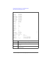
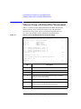
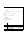
Example
ViSession vi;
ViStatus ret;
ViReal64 v1 = 3;
/* output voltage */
ViInt32 vmode = 2; /* voltage output mode */
ViInt32 mch[3];
/* source and measurement channels */
mch[0] = 1;
/* SMU1 for the 1st measurement channel*/
mch[1] = 2;
/* SMU2 for the 2nd measurement channel*/
mch[2] = 0;
ret = agb1500_setSwitch(vi, mch[0], 1);
ret = agb1500_setSwitch(vi, mch[1], 1);
ret = agb1500_force(vi, mch[0], vmode, 0, 0, 0.1, 0);
ret = agb1500_force(vi, mch[1], vmode, 0, v1, 0.1, 0);
ViInt32 mode[2];
/* measurement mode */
mode[0] = 1;
/* current measurement for 1st channel */
mode[1] = 1;
/* current measurement for 2nd channel */
ViReal64 range[2]; /* measurement range */
range[0] = 0;
/* auto ranging for 1st channel */
range[1] = 0;
/* auto ranging for 2nd channel */
ViReal64 md[2];
/* md[0],md[1]: data of 1st,2nd channel */
ViInt32 st[2];
/* st[0],st[1]: status of 1st,2nd channel */
ret = agb1500_measureM(vi, mch, mode, range, &md[0], &st[0], 0);
agb1500_measureP
This function executes a pulsed spot measurement by the specified channel, and
returns the measurement result data, measurement status, and time stamp data.
Syntax
ViStatus _VI_FUNC agb1500_measureP(ViSession vi, ViInt32 channel,
ViInt32 mode, ViReal64 range, ViPReal64 value, ViPInt32 status, ViPReal64 time);
Parameters
vi
Instrument handle returned from agb1500_init( ).
channel
Slot number of the slot that installs the SMU to be used. See
Table 2-2.
mode
Measurement mode. 1 (current) or 2 (voltage).
range
Measurement ranging mode. 0 (auto), positive value (limited
auto), or negative value (fixed range). For the available values,
see Table 2-3.
value
Measurement data. Returned data.
status
Measurement status. Returned data. See “Status Code” on page
2-14. To disable the status data output, set 0 (NULL pointer)
instead.
time
Time stamp data (measurement start time). Returned data. To
disable the time stamp data output, set 0 (NULL pointer)
instead.
Agilent B1500 VXIplug&play Driver User’s Guide, Edition 3
2-33
Driver Functions
agb1500_msweepIv
agb1500_msweepIv
This function performs sweep measurement, and returns the number of
measurement steps, sweep source data, measurement data, measurement status, and
time stamp data.
Before this function, execute the agb1500_setIv function to set the primary sweep
source and execute the agb1500_setNthSweep function to set an synchronous sweep
source. Up to nine synchronous sweep sources can be set by using the
agb1500_setNthSweep function for each channel.
Syntax
ViStatus _VI_FUNC agb1500_msweepIv(ViSession vi, ViInt32 channel,
ViInt32 mode, ViReal64 range, ViPInt32 point, ViReal64 source[ ],
ViReal64 value[ ], ViInt32 status[ ], ViPReal64 time[ ] );
Parameters
vi
Instrument handle returned from agb1500_init( ).
channel
Slot number of the slot that installs the SMU to be used. See
Table 2-2.
mode
Measurement mode. 1 (current) or 2 (voltage).
range
Measurement ranging mode. 0 (auto), positive value (limited
auto), or negative value (fixed range). For the available values,
see Table 2-3.
point
Number of measurement steps. Returned data.
source[ ]
Sweep source setup data. Returned data. To disable the source
setup data output, set 0 (NULL pointer) instead of array.
value[ ]
Measurement data. Returned data.
status[ ]
Measurement status. Returned data. See “Status Code” on page
2-14. To disable the status data output, set 0 (NULL pointer)
instead of array.
time[ ]
Time stamp data (measurement start time). Returned data. To
disable the time stamp data output, set 0 (NULL pointer)
instead of array.
Example
ViSession vi;
ViStatus ret;
ViInt32 emitter = 1;
ViInt32 base = 2;
ViInt32 collector = 4;
ViReal64 vb1 = 0.25;
ViReal64 vb2 = 0.75;
ViReal64 vc = 3;
2-34
/* SMU1 */
/* SMU2 */
/* SMU4 */
Agilent B1500 VXIplug&play Driver User’s Guide, Edition 3
Driver Functions
agb1500_msweepIv
ViReal64 ve = 0;
ViReal64 ibcomp = 0.01;
ViReal64 iccomp = 0.1;
ViReal64 iecomp = 0.1;
ViReal64 pcomp = 0;
ViInt32 nop = 11;
ViReal64 hold = 0;
ViReal64 delay = 0;
ViReal64 s_delay = 0;
ViReal64 p_comp = 0;
ViInt32 mode = 1;
ViReal64 range = 0 ;
ViInt32 rep;
ViReal64 sc[11];
ViReal64 md[11];
ViInt32 st[11];
ViReal64 tm[11];
/* current measurement */
/* auto range */
ret = agb1500_setSwitch(vi, emitter, 1);
ret = agb1500_setSwitch(vi, base, 1);
ret = agb1500_setSwitch(vi, collector, 1);
ret = agb1500_resetTimestamp(vi);
ret = agb1500_force(vi, emitter, 2, 0, ve, iecomp, 0);
ret = agb1500_force(vi, collector, 2, 0, vc, iccomp, 0);
ret = agb1500_setIv(vi, base, 1, 0, vb1, vb2, nop, hold, delay,
s_delay, ibcomp, pcomp);
ret = agb1500_msweepIv(vi, collector, mode, range, &rep, &sc[0],
&md[0], &st[0], &tm[0]);
For the above example, the array variables sc[], md[], st[], and tm[] will contain the
following data.
sc[n]: Sweep source setup data (voltage).
md[n]: Measurement data (current).
st[n]: Status for the md[n] data.
tm[n]: Time stamp data (measurement start time) for the md[n] data.
where, n = 0 to 10 (integer).
Agilent B1500 VXIplug&play Driver User’s Guide, Edition 3
2-35
Driver Functions
agb1500_msweepMiv
agb1500_msweepMiv
This function performs a multi channel sweep measurement using up to ten
measurement channels at a time, and returns the number of measurement steps,
sweep source data, measurement data, measurement status, and time stamp data.
Before this function, execute the agb1500_setIv function to set the primary sweep
source and execute the agb1500_setNthSweep function to set an synchronous sweep
source. Up to nine synchronous sweep sources can be set by using the
agb1500_setNthSweep function for each channel.
Syntax
ViStatus _VI_FUNC agb1500_msweepMiv(ViSession vi, ViInt32 channel[ ],
ViInt32 mode[ ], ViReal64 range[ ], ViPInt32 point, ViReal64 source[ ] ,
ViReal64 value[ ], ViInt32 status[ ], ViPReal64 time[ ] );
Parameters
vi
Instrument handle returned from agb1500_init( ).
channel[ ]
Slot number of the slot that installs the SMU to be used. See
Table 2-2.
Enter 0 to the last element of channel[ ]. For example, if you use
two channels, set the array size to 3, specify the channels to the
first and second elements, and enter 0 to the third element.
mode[ ]
Measurement mode. 1 (current) or 2 (voltage).
range[ ]
Measurement ranging mode. 0 (auto), positive value (limited
auto), or negative value (fixed range). For the available values,
see Table 2-3.
point
Number of measurement steps. Returned data.
source[ ]
Sweep source setup data. Returned data. To disable the source
data output, set 0 (NULL pointer) instead of array.
value[ ]
Measurement data. Returned data.
status[ ]
Measurement status. Returned data. See “Status Code” on page
2-14. To disable the status data output, set 0 (NULL pointer)
instead of array.
time[ ]
Time stamp data (measurement start time). Returned data. To
disable the time stamp data output, set 0 (NULL pointer)
instead of array.
2-36
Agilent B1500 VXIplug&play Driver User’s Guide, Edition 3
Driver Functions
agb1500_msweepMiv
Example
ViSession vi;
ViStatus ret;
ViInt32 emitter = 1;
/* SMU1 */
ViInt32 base = 2;
/* SMU2 */
ViInt32 collector = 4;
/* SMU4 */
ViReal64 vb1 = 0.25;
ViReal64 vb2 = 0.75;
ViReal64 vc = 3;
ViReal64 ve = 0;
ViReal64 ibcomp = 0.01;
ViReal64 iccomp = 0.1;
ViReal64 iecomp = 0.1;
ViReal64 pcomp = 0.01;
ViInt32 nop = 11;
ViInt32 mch[3];
ViInt32 mode[2];
ViReal64 range[2];
ViInt32 rep;
ViReal64 sc[11];
ViReal64 md[22];
ViInt32 st[22];
ViReal64 tm[22];
mch[0] = collector;
mch[1] = base;
mch[2] = 0;
mode[0] = 1;
/* current measurement */
mode[1] = 1;
/* current measurement */
range[0] = -0.1;
/* 100 mA fixed range */
range[1] = -0.0001;
/* 100 uA fixed range */
ret = agb1500_setSwitch(vi, emitter, 1);
ret = agb1500_setSwitch(vi, base, 1);
ret = agb1500_setSwitch(vi, collector, 1);
ret = agb1500_resetTimestamp(vi);
ret = agb1500_force(vi, emitter, 2, 0, ve, iecomp, 0);
ret = agb1500_force(vi, collector, 2, 0, vc, iccomp, 0);
ret = agb1500_setIv(vi, base, 1, 0, vb1, vb2, nop, 0, 0, 0, ibcomp,
pcomp);
ret = agb1500_msweepMiv(vi, mch, mode, range, &rep, &sc[0],
&md[0], &st[0], &tm[0]);
For the above example, the array variables sc[], md[], st[], and tm[] will contain the
following data.
sc[n]: Sweep source setup data (voltage).
md[2*n]: Data (current) measured by the mch[0] channel.
md[2*n+1]: Data (current) measured by the mch[1] channel.
st[2*n]: Status for the md[2*n] data.
st[2*n+1]: Status for the md[2*n+1] data.
tm[2*n]: Time stamp data (measurement start time) for the md[2*n] data.
tm[2*n+1]: Time stamp data (measurement start time) for the md[2*n+1] data.
where, n = 0 to 10 (integer).
Agilent B1500 VXIplug&play Driver User’s Guide, Edition 3
2-37
Driver Functions
agb1500_opc_Q
agb1500_opc_Q
This function does the *OPC? common command.
Syntax
ViStatus _VI_FUNC agb1500_opc_Q(ViSession vi, ViPBoolean result);
Parameters
vi
Instrument handle returned from agb1500_init( ).
result
*OPC? command execution result. Returned data. VI_TRUE
(Operation complete), or VI_FALSE (Operation is pending).
Example
ViSession vi;
ViStatus ret;
ViPBoolean result;
ret = agb1500_opc_Q(vi,&result);
agb1500_readData
This function reads and returns the source setup data or the data measured by the
agb1500_startMeasure function.
Syntax
ViStatus _VI_FUNC agb1500_readData(ViSession vi, ViPInt32 eod,
ViPInt32 data_type, ViPReal64 value, ViPInt32 status, ViPInt32 channel);
Parameters
vi
Instrument handle returned from agb1500_init( ).
eod
End of data flag. 0 (not end of data) or 1 (end of data). Returned
data.
data_type
Data type of the value. Returned data.
1: Current measurement data
2: Voltage measurement data
3: Current output data
4: Voltage output data
5: Time stamp data
6: Impedance (R-X) measurement data
7: Admittance (G-B) measurement data
8: Capacitance measurement data
9: Dissipation factor measurement data
10: Quality factor measurement data
11: Inductance measurement data
12: Phase measurement data (radian)
13: Phase measurement data (degree)
14: Frequency data
2-38
Agilent B1500 VXIplug&play Driver User’s Guide, Edition 3
Driver Functions
agb1500_readStatusByte_Q
15: Sampling index
16: Invalid data
-1: No channel related data
value
Measurement data or source setup data. Returned data.
status
Status. Returned data. See “Status Code” on page 2-14. To
disable the status data output, set 0 (NULL pointer) instead.
channel
Slot number of the slot that installs the SMU/MFCMU used for
measurement/output. Returned data.
If value is regardless of channel settings, -1 is returned.
agb1500_readStatusByte_Q
This function returns the contents of the status byte register.
Syntax
ViStatus _VI_FUNC agb1500_readStatusByte_Q(ViSession vi,
ViPInt16 statusByte);
Parameters
vi
Instrument handle returned from agb1500_init( ).
statusByte
The contents of the status byte are returned in this parameter.
Returned data.
agb1500_recoverOutput
This function returns the unit to the settings that are stored by the
agb1500_zeroOutput function, and clears the stored unit settings.
Syntax
ViStatus _VI_FUNC agb1500_recoverOutput(ViSession vi, ViInt32 channel);
Parameters
vi
Instrument handle returned from agb1500_init( ).
channel
Slot number of the slot that installs the SMU/MFCMU to return
the channel settings. See Table 2-2.
channel=0 specifies all modules.
channel=-1 detects the CMU slot automatically.
Agilent B1500 VXIplug&play Driver User’s Guide, Edition 3
2-39
Driver Functions
agb1500_reset
agb1500_reset
This function places the instrument in a default state. Before issuing this function, it
may be necessary to send a device clear to ensure that the instrument can execute a
reset. A device clear can be issued by invoking agb1500_dcl function.
Syntax
ViStatus _VI_FUNC agb1500_reset(ViSession vi);
Parameters
vi
Instrument handle returned from agb1500_init( ).
agb1500_resetTimestamp
This function clears the count of the timer (time stamp).
Syntax
ViStatus _VI_FUNC agb1500_resetTimestamp(ViSession vi);
Parameters
vi
Instrument handle returned from agb1500_init( ).
agb1500_revision_query
This function returns the driver revision and the instrument firmware revision.
Syntax
ViStatus _VI_FUNC agb1500_revision_query(ViSession vi,
ViChar_VI_FAR driver_rev[ ], ViChar _VI_FAR instr_rev[ ] );
Parameters
vi
Instrument handle returned from agb1500_init( ).
driver_rev[ ]
Instrument driver revision. Returned data. Up to 256 characters.
instr_rev[ ]
Instrument firmware revision. Returned data. Up to 256
characters.
2-40
Agilent B1500 VXIplug&play Driver User’s Guide, Edition 3
Driver Functions
agb1500_sampleIv
agb1500_sampleIv
This function executes a sampling measurement by the specified channels, and
returns the number of measurement points, measurement data index, measurement
data, measurement status, and time stamp data.
Before this function, execute the agb1500_setSample function to set the sampling
timing and execute the agb1500_setSampleMode function to set the sampling mode.
Also, execute the agb1500_addSampleSyncIv functions to set the synchronous DC
sources used with the sampling measurement channels.
Syntax
ViStatus _VI_FUNC agb1500_sampleIv(ViSession vi, ViInt32 channel[ ],
ViInt32 mode[ ], ViReal64 range[ ], ViPInt32 point, ViInt32 index[ ],
ViReal64 value[ ], ViInt32 status[ ], ViReal64 time[ ]);
Parameters
vi
Instrument handle returned from agb1500_init( ).
channel[ ]
Slot number of the slot that installs the SMU to be used. See
Table 2-2.
Enter 0 to the last element of channel[ ]. For example, if you use
two channels, set the array size to 3, specify the channels to the
first and second elements, and enter 0 to the third element.
mode[ ]
Measurement mode. 1 (current) or 2 (voltage).
range[ ]
Measurement ranging mode. 0 (auto), positive value (limited
auto), or negative value (fixed range). For the available values,
see Table 2-3.
For the linear sampling with interval < 2 msec, only the fixed
range is available. Even if range=0 or positive value is set, the
measurement channels will automatically select and use the
range that covers the compliance value set to each channel.
point
Number of measurement points. Returned data.
index[ ]
Measurement data index. Returned data.
value[ ]
Measurement data. Returned data.
status[ ]
Measurement status. Returned data. For the status value, see
“Status Code” on page 2-14. To disable the status data output,
set 0 (NULL pointer) instead of array.
time[ ]
Time stamp data (measurement start time). Returned data. To
disable the time stamp data output, set 0 (NULL pointer)
instead of array.
Agilent B1500 VXIplug&play Driver User’s Guide, Edition 3
2-41
Driver Functions
agb1500_sampleIv
Example
ViSession vi;
ViStatus ret;
ViInt32 mch[3];
/* measurement channels */
mch[0] = 1;
mch[1] = 2;
mch[2] = 0;
ret = agb1500_setSwitch(vi, mch[0], 1);
ret = agb1500_setSwitch(vi, mch[1], 1);
ViReal64 h_bias = 0.1; /* bias hold time */
ViReal64 h_base = 0.1; /* base hold time */
ViReal64 intvl = 0.01; /* sampling interval */
ViInt32 pts = 11;
/* point */
ViInt32 om = 2;
/* output mode: voltage */
ViReal64 or = 0;
/* output range: auto */
ViReal64 v1 = 0;
/* base voltage */
ViReal64 v2 = 1.5;
/* bias voltage */
ViReal64 icomp = 0.1;
/* current compliance */
ret = agb1500_setSample(vi, h_bias, h_base, intvl, pts);
ret = agb1500_setSampleMode(vi, agb1500_SAMPLE_LINEAR);
ret = agb1500_addSampleSyncIv(vi, mch[0], om, or, v1, v2, icomp);
ret = agb1500_addSampleSyncIv(vi, mch[1], om, or, v1, v2, icomp);
ret = agb1500_resetTimestamp(vi);
ViInt32 mm[2];
/* measurement mode */
ViReal64 mr[2];
/* measurement range */
mm[0] = 1;
/* current mode for mch[0] */
mm[1] = 1;
/* current mode for mch[1] */
mr[0] = 0;
/* auto range for mch[0] */
mr[1] = 0;
/* auto range for mch[1] */
ViInt32 mpts;
/* number of measurement steps */
ViReal64 idx[11];
/* data index */
ViReal64 md[22];
/* measurement data */
ViInt32 st[22];
/* status */
ViReal64 tm[22];
/* time stamp data */
ret = agb1500_sampleIv(vi, mch, mm, mr, &mpts, &idx[0], &md[0],
&st[0],&tm[0]);
For the above example, the array variables idx[], md[], st[], and tm[] will contain the
following data.
idx[n]: Data index.
md[2*n]: Data (current) measured by the mch[0] channel.
md[2*n+1]: Data (current) measured by the mch[1] channel.
st[2*n]: Status for the md[2*n] data.
st[2*n+1]: Status for the md[2*n+1] data.
tm[2*n]: Time stamp data for the md[2*n] data.
tm[2*n+1]: Time stamp data for the md[2*n+1] data.
where, n = 0 to 10 (integer).
2-42
Agilent B1500 VXIplug&play Driver User’s Guide, Edition 3
Driver Functions
agb1500_scuuLed
agb1500_scuuLed
This function is available for the Agilent B1500 installed with the multi frequency
capacitance measurement unit (MFCMU) and the SMU CMU unify unit (SCUU).
To use the SCUU, connect it to the MFCMU and two SMUs (MPSMU or HRSMU)
correctly. The SCUU cannot be used with the HPSMU or when only one SMU is
connected.
This function enables or disables the connection status indicator of the SCUU.
Syntax
ViStatus _VI_FUNC agb1500_scuuLed(ViSession vi, ViInt32 channel,
ViInt32 mode)
Parameters
vi
Instrument handle returned from agb1500_init( ).
channel
Slot number where the MFCMU has been installed. The SCUU
must be connected to the MFCMU. See Table 2-2. channel=-1
detects the slot automatically.
mode
0: Disables the indicator.
1: Enables the indicator. Initial setting.
NOTE
To use SCUU
Before turn the Agilent B1500 on, connect the SCUU to the MFCMU and two
MPSMU/HRSMUs properly. The SCUU is used to switch the module (SMU or
MFCMU) connected to the DUT.
Agilent B1500 VXIplug&play Driver User’s Guide, Edition 3
2-43
Driver Functions
agb1500_scuuPath
agb1500_scuuPath
This function is available for the Agilent B1500 installed with the multi frequency
capacitance measurement unit (MFCMU) and the SMU CMU unify unit (SCUU).
To use the SCUU, connect it to the MFCMU and two SMUs (MPSMU or HRSMU)
correctly. The SCUU cannot be used with the HPSMU or when only one SMU is
connected. This function is not effective when the High Voltage indicator of the
Agilent B1500 has been lighted.
This function controls the connection path of the SCUU and switches the SCUU
input resource (MFCMU or SMU) to be connected to its output.
When the B1500 is turned on, the SCUU input to output connection is not made
(open). When the SCUU input to output connection is made, the measurement unit
output switch will be automatically set to ON.
Syntax
ViStatus _VI_FUNC agb1500_scuuPath(ViSession vi, ViInt32 channel, ViInt32
path)
Parameters
vi
Instrument handle returned from agb1500_init( ).
channel
Slot number where the MFCMU has been installed. The SCUU
must be connected to the MFCMU. See Table 2-2. channel=-1
detects the slot automatically.
path
Path connected to the SCUU output. 1 to 4. See Table 2-9.
Remarks
When the connection is changed from SMU to MFCMU, the SMU output will be set
as follows. The other setup parameters are not changed.
Output voltage
0V
Output range
100 V
Compliance
20 mA
Series resistance
OFF
When the connection is changed from MFCMU to SMU, the SMU output will be set
as follows. The other setup parameters are not changed.
Output voltage
0V
Output range
20 V
Compliance
100 μA
Series resistance
Condition before the connection is changed from SMU to
MFCMU
2-44
Agilent B1500 VXIplug&play Driver User’s Guide, Edition 3
Driver Functions
agb1500_self_test
Table 2-9
SCUU Input Output Connection Control
SCUU output connection after the function
path
CMUH/Force1/Sense1
CMUL/Force2/Sense2
1
Force1/Sense1
Open
2
Open
Force2/Sense2
3
Force1/Sense1
Force2/Sense2
4
CMUH
CMUL
where, MFCMU will be installed in the slot numbered slot. Then, Force1/Sense1 is
connected to the SMU installed in the slot numbered slot-1. And Force2/Sense2 is
connected to the SMU installed in the slot numbered slot-2.
NOTE
To use SCUU
Before turn the Agilent B1500 on, connect the SCUU to the MFCMU and two
MPSMU/HRSMUs properly. The SCUU is used to switch the module (SMU or
MFCMU) connected to the DUT.
agb1500_self_test
This function causes the instrument to perform a self-test and returns the result of
that self-test. This is used to verify that an instrument is operating properly. A failure
may indicate a potential hardware problem.
Syntax
ViStatus _VI_FUNC agb1500_self_test(ViSession vi, ViPInt16 test_result,
ViChar_VI_FAR test_message[ ] );
Parameters
vi
Instrument handle returned from agb1500_init( ).
test_result
Numeric result from self-test operation. Returned data. If no
error is detected, 0 is returned.
test_message[ ]
Self-test status message.Returned data. Up to 256 characters.
Agilent B1500 VXIplug&play Driver User’s Guide, Edition 3
2-45
Driver Functions
agb1500_setAdc
agb1500_setAdc
This function sets the integration time or number of samples that is taken or
averaged for the measurement. See also “agb1500_setAdcType”.
Syntax
ViStatus _VI_FUNC agb1500_setAdc(ViSession vi, ViInt32 adc,
ViInt32 mode,ViInt32 value, ViInt32 autozero);
Parameters
vi
Instrument handle returned from agb1500_init( ).
adc
A/D converter type. 0 (high-speed) or 1 (high-resolution).
mode
Integration/averaging mode. 0 (auto), 1 (manual), or 2 (PLC).
value
Coefficient for a reference value to set the integration time or
number of averaging samples. 1 to 1023.
The reference value depends on the adc and mode settings:
•
For high-resolution ADC:
The reference value is the initial value for auto mode, 80 μs
for manual mode, or 1/power line frequency for PLC mode.
•
For high-speed ADC:
The reference value is the initial value for auto mode, 1
sample for manual mode, or 128 samples for PLC mode.
where initial value is the value automatically defined by the
instrument, and you cannot change.
autozero
ADC zero function. 0 (off) or 1 (on).
agb1500_setAdcType
This function selects the A/D converter type for the measurement channel.
Syntax
ViStatus _VI_FUNC agb1500_setAdcType(ViSession vi, ViInt32 channel,
ViInt32 adc);
Parameters
vi
Instrument handle returned from agb1500_init( ).
channel
Slot number of the slot that installs the SMU used to perform
measurement. See Table 2-2. Set 0 to select all SMUs.
adc
A/D converter type. 0 (high-speed) or 1 (high-resolution).
2-46
Agilent B1500 VXIplug&play Driver User’s Guide, Edition 3
Driver Functions
agb1500_setBdv
agb1500_setBdv
This function sets the quasi pulse source used to perform breakdown voltage
measurement. After the source setup, execute the agb1500_measureBdv function to
trigger the measurement.
After the measurement trigger, the quasi pulse source keeps the start voltage during
the hold time. After the hold time, the quasi pulse source starts the voltage transition
and settling detection. And the source stops the settling detection and keeps the
output when the following condition a or b occurs. After the delay time, the
measurement channel starts breakdown voltage measurement.
Condition:
a. Quasi-pulse source reaches it current compliance setting.
b. Output voltage slew rate becomes 1/2 of the rate when starting the settling
detection.
The condition b means that the quasi-pulse source applies the voltage close to the
stop voltage, or the device under test reaches the breakdown condition.
Syntax
ViStatus _VI_FUNC agb1500_setBdv(ViSession vi, ViInt32 channel,
ViReal64 range, ViReal64 start, ViReal64 stop, ViReal64 current, ViReal64 hold,
ViReal64 delay);
Parameters
vi
Instrument handle returned from agb1500_init( ).
channel
Slot number of the slot that installs the SMU to be used. See
Table 2-2.
range
Voltage output ranging mode. 0 (auto) or positive value (limited
auto). For the available values, see Table 2-3 and Table 2-4.
start, stop
Start voltage and stop voltage (in V). See Table 2-4. Difference
between start and stop must be 10 V or more.
current
Current compliance (in A). See Table 2-4.
hold
Hold time (in seconds). 0 to 655.35 s, 0.01 s resolution.
delay
Delay time (in seconds). 0 to 6.5535 s, 0.0001 s resolution.
Agilent B1500 VXIplug&play Driver User’s Guide, Edition 3
2-47
Driver Functions
agb1500_setCmuAdjustMode
agb1500_setCmuAdjustMode
This function selects the phase compensation mode of the MFCMU. After this
function, the MFCMU is initialized.
Syntax
ViStatus _VI_FUNC agb1500_setCmuAdjustMode(ViSession vi, ViInt32 channel,
ViInt32 mode);
Parameters
vi
Instrument handle returned from agb1500_init( ).
channel
Slot number of the slot that installs the MFCMU to be used. See
Table 2-2. channel=-1 detects the slot automatically.
mode
0: Auto mode. The B1500 sets the compensation data
automatically.
1: Manual mode. Execute the agb1500_execCmuAdjust
function to perform the phase compensation and set the
compensation data.
agb1500_setCmuFreq
This function sets the frequency of the AC voltage forced by the MFCMU. The AC
voltage output will be triggered by the agb1500_forceCmuAcLevel.
Syntax
ViStatus _VI_FUNC agb1500_setCmuFreq(ViSession vi, ViInt32 channel,
ViReal64 value);
Parameters
vi
Instrument handle returned from agb1500_init( ).
channel
Slot number of the slot that installs the MFCMU to be used. See
Table 2-2. channel=-1 detects the slot automatically.
value
Frequency (in Hz). Numeric expression.
1000 (1 kHz, initial setting) to 5000000 (5 MHz)
Setting resolution: 1 mHz (1 kHz to), 10 mHz (10 kHz to),
0.1 Hz (100 kHz to), or 1 Hz (1 MHz to 5 MHz).
agb1500_setCmuInteg
This function sets the number of averaging samples or the averaging time set to the
A/D converter of the MFCMU.
2-48
Agilent B1500 VXIplug&play Driver User’s Guide, Edition 3
Driver Functions
agb1500_setCv
Syntax
ViStatus _VI_FUNC agb1500_setCmuInteg(ViSession vi, ViInt32 mode,
ViInt32 value);
Parameters
vi
Instrument handle returned from agb1500_init( ).
mode
Integration/averaging mode. 0 (auto) or 2 (PLC).
value
Coefficient for a reference value to set the integration time or
number of averaging samples. 1 to 1023 for auto mode, or 1 to
100 for PLC mode.
The reference value depends on the mode settings:
•
For auto mode:
The reference value is the number of averaging samples that
is automatically set by the B1500. You cannot change it.
•
For PLC mode:
The reference value is the averaging time (1/power line
frequency).
agb1500_setCv
This function specifies staircase sweep voltage source and sets the parameters. The
sweep source is used for the CV sweep measurement.
Syntax
ViStatus _VI_FUNC agb1500_setCv(ViSession vi, ViInt32 channel, ViInt32 mode,
ViReal64 start, ViReal64 stop, ViInt32 point, ViReal64 hold, ViReal64 delay,
ViReal64 s_delay);
Parameters
vi
Instrument handle returned from agb1500_init( ).
channel
Slot number of the slot that installs the MFCMU to be used. See
Table 2-2. channel=-1 detects the slot automatically.
mode
Source output mode. 1, 2, 3, or 4. For the log sweep mode, start
and stop must be the same polarity.
1: Single-Linear sweep
2: Single-Log sweep
3: Double-Linear sweep
4: Double-Log sweep
start, stop
Start or stop voltage (in V). Numeric expression. start and stop
must have the same polarity for log sweep.
0 (initial setting) to ±100 V
Agilent B1500 VXIplug&play Driver User’s Guide, Edition 3
2-49
Driver Functions
agb1500_setFilter
Source module is automatically selected by the setting value.
The MFCMU is selected if the voltage from start to stop is
±25 V or less (setting resolution: 0.001 V), or the SMU is
selected if it is greater than ±25 V (setting resolution: 0.005 V).
The SMU will operate with the 100 V limited auto ranging and
20 mA compliance settings.
point
Number of sweep steps. 1 to 1001.
hold
Hold time. 0 to 655.35 seconds, in 0.01 ms resolution.
delay
Delay time. 0 to 655.35 seconds, in 0.01 ms resolution.
s_delay
Step delay time. 0 to 1.0 seconds, in 0.1 ms resolution.
agb1500_setFilter
This function sets the output filter of the specified channel.
Syntax
ViStatus _VI_FUNC agb1500_setFilter(ViSession vi, ViInt32 channel,
ViInt32 state);
Parameters
vi
Instrument handle returned from agb1500_init( ).
channel
Slot number of the slot that installs the SMU to change the filter
state. See Table 2-2. Set 0 to select all SMUs.
state
0 (off) or 1 (on).
agb1500_setIleak
This function sets the quasi pulse source used to perform leakage current
measurement. After the source setup, execute the agb1500_measureIleak function to
trigger the measurement.
After the measurement trigger, the quasi pulse source keeps the start voltage during
the hold time. After the hold time, the quasi pulse source starts the voltage transition
and settling detection. And the source stops the settling detection and keeps the
output when the following condition a or b occurs. After the delay time, the
measurement channel starts leakage current measurement.
Condition:
a. Quasi-pulse source reaches it current compliance setting.
2-50
Agilent B1500 VXIplug&play Driver User’s Guide, Edition 3
Driver Functions
agb1500_setIv
b. Output voltage slew rate becomes 1/2 of the rate when starting the settling
detection.
The condition b means that the quasi-pulse source applies the voltage close to the
measurement voltage.
Syntax
ViStatus _VI_FUNC agb1500_setIleak(ViSession vi, ViInt32 channel,
ViReal64 range, ViReal64 voltage, ViReal64 compliance, ViReal64 start, ViReal64
hold, ViReal64 delay);
Parameters
vi
Instrument handle returned from agb1500_init( ).
channel
Slot number of the slot that installs the SMU to be used. See
Table 2-2.
range
Voltage output ranging mode. 0 (auto) or positive value (limited
auto). For the available values, see Table 2-3 and Table 2-4.
start, voltage
Start voltage and measurement voltage (in V). See Table 2-4.
Difference between start and voltage must be 10 V or more.
current
Current compliance (in A). See Table 2-4.
hold
Hold time (in seconds). 0 to 655.35 s, 0.01 s resolution.
delay
Delay time (in seconds). 0 to 6.5535 s, 0.0001 s resolution.
agb1500_setIv
This function specifies staircase sweep source and sets the parameters. The sweep
source is used for the staircase sweep measurements and the staircase sweep with
pulsed bias measurements.
For the staircase sweep with pulsed bias measurements, the sweep output
synchronizes with the pulse output by the agb1500_setPbias function.
Syntax
ViStatus _VI_FUNC agb1500_setIv(ViSession vi, ViInt32 channel, ViInt32 mode,
ViReal64 range, ViReal64 start, ViReal64 stop, ViInt32 point, ViReal64 hold,
ViReal64 delay, ViReal64 s_delay, ViReal64 comp, ViReal64 p_comp);
NOTE
range, start, stop, comp parameters
Available values depend on the unit. See “Parameters” on page 2-8.
Parameters
vi
Instrument handle returned from agb1500_init( ).
Agilent B1500 VXIplug&play Driver User’s Guide, Edition 3
2-51
Driver Functions
agb1500_setLoadCorrMode
channel
Slot number of the slot that installs the SMU to be used. See
Table 2-2.
mode
Source output mode. 1, 2, 3, 4, -1, -2, -3, or -4. For the log
sweep mode, start and stop must be the same polarity.
1: Voltage-Single-Linear sweep
2: Voltage-Single-Log sweep
3: Voltage-Double-Linear sweep
4: Voltage-Double-Log sweep
-1: Current-Single-Linear sweep (only for SMU)
-2: Current-Single-Log sweep (only for SMU)
-3: Current-Double-Linear sweep (only for SMU)
-4: Current-Double-Log sweep (only for SMU)
range
Output ranging mode. 0 (auto) or positive value (limited auto).
start
Sweep start value (in A or V).
stop
Sweep stop value (in A or V).
point
Number of sweep steps. 1 to 1001.
hold
Hold time. 0 to 655.35 seconds, in 0.01 seconds resolution.
delay
Delay time. 0 to 65.535 seconds, in 0.0001 seconds resolution.
s_delay
Step delay time. 0 to 1.0 seconds, in 0.0001 seconds resolution.
comp
Compliance value (in V or A). It must be voltage for the current
sweep source, or current for the voltage sweep source.
Compliance polarity is automatically set to the same polarity as
the output value, regardless of the specified comp polarity. The
compliance polarity is positive if the output value is 0.
p_comp
Power compliance. Available values are listed below. If you
enter the other value, the power compliance is not set.
0.001 to 4.0 VA (for MPSMU)
0.001 to 20.0 VA (for HPSMU)
Setting resolution: 0.001 VA
agb1500_setLoadCorrMode
This function sets the CMU load correction function ON or OFF.
The agb1500_execLoadCorr function must be executed before this function.
2-52
Agilent B1500 VXIplug&play Driver User’s Guide, Edition 3
Driver Functions
agb1500_setNthSweep
Syntax
ViStatus _VI_FUNC agb1500_setLoadCorrMode(ViSession vi, ViInt32 channel,
ViInt32 mode);
Parameters
vi
Instrument handle returned from agb1500_init( ).
channel
Slot number of the slot that installs the MFCMU to be used. See
Table 2-2. channel=-1 detects the slot automatically.
mode
0: CMU load correction function ON.
1: CMU load correction function OFF.
agb1500_setNthSweep
This function sets the synchronous sweep source for the multi channel sweep
measurements. Up to nine synchronous sweep sources can be set by entering this
function for each channel. The source output is the staircase sweep, and
synchronizes with the primary sweep source output. The agb1500_setIv function
must be executed before this function.
To perform the multi channel sweep measurements, execute the agb1500_setIv
function to set the primary sweep source (first sweep source), and execute the
agb1500_msweepIv or agb1500_msweepMiv function to start measurement. The
agb1500_msweepMiv function allows to use multiple measurement channels.
Syntax
ViStatus _VI_FUNC agb1500_setNthSweep(ViSession vi, ViInt32 n,
ViInt32 channel, ViInt32 mode, ViReal64 range, ViReal64 start, ViReal64 stop,
ViReal64 comp, ViReal64 p_comp);
NOTE
range, start, stop, comp parameters
Available values depend on the unit. See “Parameters” on page 2-8.
Sweep type, linear or log, is set by the agb1500_setIv function. If the function sets
the log sweep, start and stop must be the same polarity.
Parameters
vi
Instrument handle returned from agb1500_init( ).
n
Sweep source ID. 2 for the second sweep source (first
synchronous sweep source), 3 for the third sweep source
(second synchronous sweep source), ..., or 10 for the tenth
sweep source (ninth synchronous sweep source).
channel
Slot number of the slot that installs the SMU to be used. See
Table 2-2.
Agilent B1500 VXIplug&play Driver User’s Guide, Edition 3
2-53
Driver Functions
agb1500_setOpenCorrMode
mode
Source output mode. 1 (current) or 2 (voltage).
range
Output ranging mode. 0 (auto) or positive value (limited auto).
start
Sweep start value (in A or V).
stop
Sweep stop value (in A or V).
comp
Compliance value (in V or A). It must be voltage for the current
sweep source, or current for the voltage sweep source.
Compliance polarity is automatically set to the same polarity as
the output value, regardless of the specified comp polarity. The
compliance polarity is positive if the output value is 0.
p_comp
Power compliance. Available values are listed below. If you
enter the other value, the power compliance is not set.
0.001 to 4.0 VA, 0.001 VA resolution (for MPSMU)
0.001 to 20.0 VA, 0.001 VA resolution (for HPSMU)
agb1500_setOpenCorrMode
This function sets the CMU open correction function ON or OFF.
The agb1500_execOpenCorr function must be executed before this function.
Syntax
ViStatus _VI_FUNC agb1500_setOpenCorrMode(ViSession vi, ViInt32 channel,
ViInt32 mode);
Parameters
vi
Instrument handle returned from agb1500_init( ).
channel
Slot number of the slot that installs the MFCMU to be used. See
Table 2-2. channel=-1 detects the slot automatically.
mode
0: CMU open correction function ON.
1: CMU open correction function OFF.
agb1500_setPbias
This function specifies pulse source and sets the parameters. The pulse source is
used for the pulsed spot measurements and the staircase sweep with pulsed bias
measurements. For the staircase sweep with pulsed bias measurements, the pulse
output synchronizes with the staircase sweep output by the agb1500_setIv function.
2-54
Agilent B1500 VXIplug&play Driver User’s Guide, Edition 3
Driver Functions
agb1500_setPbias
Measurement channel always uses the high-speed A/D converter, and performs
measurement so that the pulse width and pulse period are kept. The integration time
is automatically set by the Agilent B1500, and you cannot change. The
agb1500_setAdc and agb1500_setAdcType settings are ignored. Also the timing
parameters of the agb1500_setIv function are also ignored.
Syntax
ViStatus _VI_FUNC agb1500_setPbias(ViSession vi, ViInt32 channel,
ViInt32 mode, ViReal64 range, ViReal64 base, ViReal64 peak, ViReal64 width,
ViReal64 period, ViReal64 hold, ViReal64 comp);
NOTE
range, base, peak, comp parameters
Available values depend on the unit. See “Parameters” on page 2-8.
Parameters
vi
Instrument handle returned from agb1500_init( ).
channel
Slot number of the slot that installs the SMU to be used. See
Table 2-2.
mode
Pulse output mode. 1 (current), or 2 (voltage). For the current
output, base and peak must be the same polarity.
range
Output ranging mode. 0 (auto) or positive value (limited auto).
base
Pulse base value (in A or V).
peak
Pulse peak value (in A or V).
width
Pulse width (in seconds). 0.0005 to 2.0 s. 0.0001 s resolution.
period
Pulse period (in seconds). 0.005 to 5.0 s. 0.0001 s resolution.
•
period ≥ width +2 msec (for width ≤ 100 ms)
•
period ≥ width +10 msec (for width > 100 ms)
If you set period=0, the B1500 automatically sets the pulse
period to 5 msec (for width ≤ 3 ms), width +2 msec (for 3 ms <
width ≤ 100 ms), or width +10 msec (for width > 100 ms).
hold
Hold time (in seconds). 0.0 to 655.35 sec. 0.01 sec resolution.
comp
Compliance value (in V or A). It must be voltage for the current
source, or current for the voltage source. Compliance polarity is
automatically set to the same polarity as the output value,
regardless of the specified comp polarity. The compliance
polarity is positive if the output value is 0.
Agilent B1500 VXIplug&play Driver User’s Guide, Edition 3
2-55
Driver Functions
agb1500_setPiv
agb1500_setPiv
This function specifies pulsed sweep source and sets the parameters. The pulsed
sweep source is used for the pulsed sweep measurements.
Measurement channel always uses the high-speed A/D converter, and performs
measurement so that the pulse width and pulse period are kept. The integration time
is automatically set by the Agilent B1500, and you cannot change. The
agb1500_setAdc and agb1500_setAdcType settings are ignored. Also the timing
parameters of the agb1500_setIv function are also ignored.
Syntax
ViStatus _VI_FUNC agb1500_setPiv(ViSession vi, ViInt32 channel, ViInt32 mode,
ViReal64 range, ViReal64 base, ViReal64 start, ViReal64 stop, ViInt32 point,
ViReal64 hold, ViReal64 width, ViReal64 period, ViReal64 comp);
NOTE
range, base, start, stop, comp parameters
Available values depend on the unit. See “Parameters” on page 2-8.
Parameters
vi
Instrument handle returned from agb1500_init( ).
channel
Slot number of the slot that installs the SMU to be used. See
Table 2-2.
mode
Pulse output mode. 1, 3, -1, or -3. For the current output, base,
start, and stop must be the same polarity.
1: Voltage-Single-Linear sweep
3: Voltage-Double-Linear sweep
-1: Current-Single-Linear sweep
-3: Current-Double-Linear sweep
range
Output ranging mode. 0 (auto) or positive value (limited auto).
base
Pulse sweep base value (in A or V).
start
Pulse sweep start value (in A or V).
stop
Pulse sweep stop value (in A or V).
point
Number of sweep steps. 1 to 1001.
hold
Hold time (in seconds). 0.0 to 655.35 sec. 0.01 sec resolution.
width
Pulse width (in seconds). 0.0005 to 2.0 s. 0.1 ms resolution.
2-56
Agilent B1500 VXIplug&play Driver User’s Guide, Edition 3
Driver Functions
agb1500_setSample
period
Pulse period (in seconds). 0.005 to 5.0 s. 0.1 ms resolution.
•
period ≥ width +2 msec (for width ≤ 100 ms)
•
period ≥ width +10 msec (for width > 100 ms)
If you set period=0, the B1500 automatically sets the pulse
period to 5 msec (for width ≤ 3 ms), width +2 msec (for 3 ms <
width ≤ 100 ms), or width +10 msec (for width > 100 ms).
comp
Compliance value (in V or A). It must be voltage for the current
sweep source, or current for the voltage sweep source.
Compliance polarity is automatically set to the same polarity as
the output value, regardless of the specified comp polarity. The
compliance polarity is positive if the output value is 0.
agb1500_setSample
This function sets the timing parameters of the sampling measurement.
To set the synchronous constant voltage/current source for the sampling
measurement, execute the agb1500_addSampleSyncIv function. To set the linear or
logarithmic sampling mode, execute the agb1500_setSampleMode function. To set
the automatic measurement abort function and the post measurement output value,
execute the agb1500_stopMode function. To define the measurement channels and
start the measurement, execute the agb1500_sampleIv function.
Syntax
ViStatus _VI_FUNC agb1500_setSample(ViSession vi, ViReal64 bias_hold,
ViReal64 base_hold, ViReal64 interval, ViInt32 point);
Parameters
vi
Instrument handle returned from agb1500_init( ).
bias_hold
Time since the bias value output until the first sampling point.
Numeric expression. in seconds. 0 (initial setting) to 655.35 s,
resolution 0.01 s.
The following values are also available for interval < 0.002 s.
|bias_hold| will be the time since the sampling start until the
bias value output.
-0.09 to -0.0001 s, resolution 0.0001 s.
base_hold
Hold time of the base value output until the bias value output.
Numeric expression. in seconds. 0 (initial setting) to 655.35 s,
resolution 0.01 s.
Agilent B1500 VXIplug&play Driver User’s Guide, Edition 3
2-57
Driver Functions
agb1500_setSample
interval
Interval of the sampling. Numeric expression. in seconds.
0.002 (initial setting) to 65.535 s, 0.001 s resolution.
interval < 0.002 s in 0.00001 s resolution is also available for
the linear sampling. It must satisfy the following formula. See
NOTE below.
interval ≥ 0.0001 + 0.00002 × (Num_ch -1)
Num_ch: number of measurement channels
point
Number of samples. Integer expression. 1 to the following
value.
For linear: 100001 / (number of measurement channels)
For log: 1 + (number of data for 11 decades)
NOTE
If you set interval < 0.002 s
Sampling mode must be linear. This setting is not permitted for the log sampling.
All measurement channels must use the high speed A/D converter (ADC). This
setting is not permitted if a measurement channel uses the high resolution ADC.
If the multiple measurement channels are used, all channels perform measurements
in parallel.
If the measurement ranging mode is not the fixed mode, the measurement channels
automatically select the minimum range that covers compliance value set to the
channel.
If the measurement time is expected to be longer than interval, the measurement
channels automatically adjust the number of averaging samples (agb1500_setAdc
settings) to keep the sampling interval.
Sampling
Operation
Sampling measurement will be started by the agb1500_sampleIv function, and
performed as shown below. Before the measurement trigger, the agb1500_force
output channels will start the output at the timing of the function execution.
1. By the measurement trigger, the agb1500_addSampleSyncIv output channels
start the base value output. Each channel controls the output simultaneously.
2. base_hold seconds later, the source channels change the output to the bias value.
The channels keep the value until the end of the sampling measurement.
2-58
Agilent B1500 VXIplug&play Driver User’s Guide, Edition 3
Driver Functions
agb1500_setSampleMode
3. Another bias_hold seconds later, the measurement channels start measurement
for the first sampling point. The measurement channels perform the
measurement in series by the order set to the agb1500_sampleIv function.
4. After that, the following operation is repeated with the specified time interval.
•
Measurement channels start measurement if they are ready to measure.
•
Measurement channels keep the condition if they are busy.
This operation is repeated until the number of measurement result data reaches
to the specified point of measurement data.
For the linear sampling with interval < 2 ms, if the total measurement time runs
over the specified time interval × point, the sampling measurement will be
stopped even if the number of measurement result data is less than the specified
point.
For the log sampling, the B1500A holds only the data that can be plotted on the
log scale in the same distance as close as possible. Only the held data is counted
in the number of measurement result data.
5. The sampling measurement is completed. And the agb1500_addSampleSyncIv
output channel forces the base or bias value specified by the agb1500_stopMode
function. The agb1500_force output channel keeps its output.
The index data and the time data returned with the measurement data will be as
shown in the following formula. However, long measurement or busy status may
cause unexpected time data.
time data = t + bias_hold + ( index data -1) × interval
Where, t is the time of the sampling measurement time origin, and is the time when
the output value is changed from base to bias.
agb1500_setSampleMode
This function sets the sampling mode, linear or logarithmic. For the logarithmic
sampling, this function also specify the number of measurement data to be returned.
If you do not execute this function, the last sampling mode is effective. Initialization
such as the agb1500_reset function sets the linear sampling mode.
Syntax
ViStatus _VI_FUNC agb1500_setSampleMode(ViSession vi, ViInt32 mode);
Parameters
vi
Instrument handle returned from agb1500_init( ).
Agilent B1500 VXIplug&play Driver User’s Guide, Edition 3
2-59
Driver Functions
agb1500_setSerRes
mode
Sampling mode, linear or logarithm.
0: linear sampling
1: logarithmic sampling, 10 data/decade.
2: logarithmic sampling, 25 data/decade.
3: logarithmic sampling, 50 data/decade.
4: logarithmic sampling, 100 data/decade.
5: logarithmic sampling, 250 data/decade.
6: logarithmic sampling, 500 data/decade.
agb1500_setSerRes
This function sets the series resistor of the specified channel.
Syntax
ViStatus _VI_FUNC agb1500_setSerRes(ViSession vi, ViInt32 channel,
ViInt32 state);
Parameters
vi
Instrument handle returned from agb1500_init( ).
channel
Slot number of the slot that installs the SMU to be used. See
Table 2-2. Set 0 to select all SMUs.
state
0 (disconnects resistor) or 1 (connects resistor).
agb1500_setShortCorrMode
This function sets the CMU short correction function ON or OFF.
The agb1500_execShortCorr function must be executed before this function.
Syntax
ViStatus _VI_FUNC agb1500_setShortCorrMode(ViSession vi, ViInt32 channel,
ViInt32 mode);
Parameters
vi
Instrument handle returned from agb1500_init( ).
channel
Slot number of the slot that installs the MFCMU to be used. See
Table 2-2. channel=-1 detects the slot automatically.
mode
0: CMU short correction function ON.
1: CMU short correction function OFF.
2-60
Agilent B1500 VXIplug&play Driver User’s Guide, Edition 3
Driver Functions
agb1500_setSweepSync
agb1500_setSweepSync
This function specifies synchronous sweep source and sets the parameters. The
synchronous sweep source will be the additional staircase sweep source for the
staircase sweep measurements, the pulsed sweep measurements, or the staircase
sweep with pulsed bias measurements. The agb1500_setIv or agb1500_setPiv
function must be executed before this function.
For the staircase sweep measurements, the output synchronizes with the staircase
sweep output by the agb1500_setIv function.
For the pulsed sweep measurements, the output synchronizes with the pulsed sweep
output by the agb1500_setPiv function.
For the staircase sweep with pulsed bias measurements, the output synchronizes the
staircase sweep output by the agb1500_setIv function and the pulse output by the
agb1500_setPbias function.
Syntax
ViStatus _VI_FUNC agb1500_setSweepSync(ViSession vi, ViInt32 channel,
ViInt32 mode, ViReal64 range, ViReal64 start, ViReal64 stop, ViReal64 comp,
ViReal64 p_comp);
NOTE
range, start, stop, comp parameters
Available values depend on the unit. See “Parameters” on page 2-8
Sweep type, linear or log, is set by the agb1500_setIv function. If the function sets
the log sweep, start and stop must be the same polarity.
Parameters
vi
Instrument handle returned from agb1500_init( ).
channel
Slot number of the slot that installs the SMU to be used. See
Table 2-2.
mode
Source output mode. 1 (current) or 2 (voltage).
Set 1 if the agb1500_setIv or agb1500_setPiv function sets the
current output mode. Or, set 2 if the function sets the voltage
output mode.
range
Output ranging mode. 0 (auto) or positive value (limited auto).
start
Sweep start value (in A or V).
stop
Sweep stop value (in A or V).
Agilent B1500 VXIplug&play Driver User’s Guide, Edition 3
2-61
Driver Functions
agb1500_setSwitch
comp
Compliance value (in V or A). It must be voltage for the current
sweep source, or current for the voltage sweep source.
Compliance polarity is automatically set to the same polarity as
the output value, regardless of the specified comp polarity. The
compliance polarity is positive if the output value is 0.
p_comp
Power compliance. 0.001 to 4.0 VA (for MPSMU), or 0.001 to
20.0 VA (for HPSMU) in 0.001 VA resolution. If you enter the
other value, the power compliance is not set.
agb1500_setSwitch
This function sets the output switch of the specified channel.
Syntax
ViStatus _VI_FUNC agb1500_setSwitch(ViSession vi, ViInt32 channel,
ViInt32 state);
Parameters
vi
Instrument handle returned from agb1500_init( ).
channel
Slot number of the slot that installs the SMU/MFCMU to be
used. See Table 2-2.
channel=0 specifies all modules.
channel=-1 detects the CMU slot automatically.
state
Output switch setting. 0 (off) or 1 (on).
agb1500_spotCmuMeas
This function executes the high speed spot C measurement, and returns the
measurement data, measurement status, MFCMU monitor data, MFCMU monitor
status, and time stamp data.
Before this function, execute the agb1500_setCmuFreq,
agb1500_forceCmuAcLevel, and agb1500_forceCmuDcBias functions to set the
oscillator and DC bias source.
Syntax
ViStatus _VI_FUNC agb1500_spotCmuMeas(ViSession vi, ViInt32 channel,
ViInt32 mode, ViReal64 range, ViReal64 value[], ViInt32 status[],
ViReal64 monitor[],ViInt32 status_mon[], ViPReal64 time);
Parameters
vi
2-62
Instrument handle returned from agb1500_init( ).
Agilent B1500 VXIplug&play Driver User’s Guide, Edition 3
Driver Functions
agb1500_spotCmuMeas
Example
channel
Slot number of the slot that installs the MFCMU. See Table 2-2.
channel=-1 detects the slot automatically.
mode
MFCMU measurement parameters. 1 to 402. See Table 2-6.
Specify a couple of measurement parameters. The MFCMU can
measure two parameters.
range
MFCMU measurement range. 0 (auto) or positive value (fixed
range). See Table 2-7.
value[ ]
Measurement data. Returned data.
status[ ]
Measurement status. Returned data. See “Status Code” on page
2-14. To disable the status data output, set 0 (NULL pointer)
instead of array.
monitor[ ]
MFCMU output (oscillator level and DC bias) monitor data.
Returned data. To disable the AC/DC monitor data output, set 0
(NULL pointer) instead of array.
status_mon[ ]
MFCMU output monitor status. Returned data. To disable the
status output, set 0 (NULL pointer) instead of array.
time
Time stamp data (measurement start time). Returned data. To
disable the time stamp data output, set 0 (NULL pointer)
instead of variable.
ViSession vi;
ViStatus ret;
ViInt32 ch = 9;
/* MFCMU */
ViReal64 freq = 1E6; /* frequency */
ViReal64 acv = 0.05; /* oscillator level */
ViReal64 dcv = 2.5;
/* DC bias */
ViInt32 mm = 100;
/* measurement mode: Cp-G */
ViReal64 mr = 0;
/* measurement range: auto */
ViReal64 md[2];
/* measurement data */
ViInt32 st[2];
/* status */
ViReal64 mon[2];
/* monitor data */
ViInt32 stmon[2];
/* monitor status */
ViInt32 tm;
/* time stamp data */
ret = agb1500_setSwitch(vi, ch, 1);
ret = agb1500_setCmuFreq(vi, ch, freq);
ret = agb1500_forceCmuAcLevel(vi, ch, acv);
ret = agb1500_forceCmuDcBias(vi, ch, dcv);
ret = agb1500_resetTimestamp(vi);
ret = agb1500_spotCmuMeas(vi, ch, mm, mr, &md[0], &st[0], &mon[0],
&stmon[0], &tm);
For the above example, the array variables md[], st[], mon[], and stmon[] will
contain the following data.
md[0]: Primary parameter measurement data (ex: Cp).
Agilent B1500 VXIplug&play Driver User’s Guide, Edition 3
2-63
Driver Functions
agb1500_spotMeas
md[1]: Secondary parameter measurement data (ex: G).
st[n]: Status for the md[n] data.
mon[0]: MFCMU monitor data (AC level monitor data).
mon[1]: MFCMU monitor data (DC bias monitor data).
stmon[n]: Status for the mon[n] data.
where n=0 or 1.
agb1500_spotMeas
This function executes a high speed spot measurement by the specified channel, and
returns the measurement result data, measurement status, and time stamp data.
Syntax
ViStatus _VI_FUNC agb1500_spotMeas(ViSession vi, ViInt32 channel,
ViInt32 mode, ViReal64 range, ViPReal64 value, ViPInt32 status, ViPReal64 time);
Parameters
vi
Instrument handle returned from agb1500_init( ).
channel
Slot number of the slot that installs the SMU to be used. See
Table 2-2.
mode
Measurement mode. 1 (current) or 2 (voltage).
range
Measurement ranging mode. 0 (auto), positive value (limited
auto), or negative value (fixed range). For the available values,
see Table 2-3.
value
Measurement data. Returned data.
status
Measurement status. Returned data. See “Status Code” on page
2-14. To disable the status data output, set 0 (NULL pointer)
instead.
time
Time stamp data (measurement start time). Returned data. To
disable the time stamp data output, set 0 (NULL pointer)
instead.
2-64
Agilent B1500 VXIplug&play Driver User’s Guide, Edition 3
Driver Functions
agb1500_startMeasure
agb1500_startMeasure
This function starts the specified measurement by the specified channels. You can
read the measured data by using the agb1500_readData function. The measurement
data is entered to the B1500 output buffer in the measurement order. If you want to
abort the measurement, use the agb1500_abortMeasure function.
Syntax
ViStatus _VI_FUNC agb1500_startMeasure(ViSession vi, ViInt32 meas_type,
ViInt32 channel[ ], ViInt32 mode[ ], ViReal64 range[ ], ViInt32 source,
ViInt32 timestamp, ViInt32 monitor);
Parameters
vi
Instrument handle returned from agb1500_init( ).
meas_type
Measurement type.
1: multi spot
2: staircase sweep
3: pulse spot
4: pulse sweep
5: sweep with pulsed bias
9: quasi pulsed spot
10: sampling (IV)
14: linear search
15: binary search
16: multi channel sweep
17: spot C
18: CV sweep
channel[ ]
Slot number of the slot that installs the SMU/MFCMU to be
used. See Table 2-2.
channel=-1 detects the CMU slot automatically.
Enter 0 to the last element of channel[ ]. For example, if you use
two channels, set the array size to 3, specify the channels to the
first and second elements, and enter 0 to the third element.
For meas_type=1, 2, 10, or 16, up to ten measurement channels
can be set.
For meas_type=3, 4, 5, 9, 17, or 18, only one measurement
channel can be set.
For meas_type=14 or 15, set 0 (NULL pointer) instead of
channel [ ].
mode[ ]
Measurement mode.
Agilent B1500 VXIplug&play Driver User’s Guide, Edition 3
2-65
Driver Functions
agb1500_startMeasure
For SMU: 1 (current) or 2 (voltage).
For MFCMU: 1 to 402. See Table 2-6.
range[ ]
Measurement ranging mode.
For SMU: 0 (auto), positive value (limited auto), or negative
value (fixed range). See Table 2-3.
For MFCMU: 0 (auto) or positive value (fixed range). See
Table 2-7.
source
Enables or disables source data output. 0 (disable) or 1 (enable).
For meas_type=9, 14, and 15, enter 0 (zero). Source data output
is not available for these measurement types.
timestamp
Enables or disables time stamp data output. Time stamp data is
the measurement start time. 0 (disable) or 1 (enable).
For meas_type=9, 14, and 15, enter 0 (zero). Time stamp data
output is not available for these measurement types.
monitor
Enables or disables MFCMU monitor data output. 0 (disable) or
1 (enable). If monitor=1, the MFCMU AC output level monitor
data and DC bias monitor data will be returned.
This parameter is available only for meas_type=17 and 18. For
the other measurement types, enter 0 (zero).
Example
ViSession vi;
ViStatus ret;
ViInt32 mch[3];
mch[0] = 1;
mch[1] = 2;
mch[2] = 0;
/* channel */
/* SMU1 for the 1st measurement channel*/
/* SMU2 for the 2nd measurement channel*/
ret = agb1500_setSwitch(vi, mch[0], 1);
ret = agb1500_setSwitch(vi, mch[1], 1);
ViInt32 om = 2;
ViReal64 or = 0;
ViReal64 v1 = 0;
ViReal64 v2 = 1.5;
ViReal64 tw = 0.001;
ViReal64 tp = 0.01;
ViReal64 th = 0;
ViReal64 ic = 0.01;
/*
/*
/*
/*
/*
/*
/*
/*
output mode: voltage */
output range: auto */
base voltage */
peak voltage */
width */
period */
hold time */
current compliance */
ret= agb1500_setPbias(vi, mch[0], om, or, v1, v2, tw, tp, th, ic);
ret= agb1500_force(vi, mch[1], om, or, v1, ic, 0);
ViInt32 type = 3;
ViInt32 mode[2];
2-66
/* pulsed spot measurement */
/* measurement mode */
Agilent B1500 VXIplug&play Driver User’s Guide, Edition 3
Driver Functions
agb1500_stopMode
ViReal64 range[2];
mode[0] = 1;
mode[1] = 1;
range[0] = 0;
range[1] = 0;
/*
/*
/*
/*
/*
measurement range */
current for 1st measurement channel */
current for 2nd measurement channel */
auto for 1st measurement channel */
auto for 2nd measurement channel */
ret = agb1500_startMeasure(vi, type, mch, mode, range, 0, 0, 0);
ViInt32 eod;
ViInt32 dtype;
ViReal64 md;
ViInt32 st;
ViInt32 ch;
/*
/*
/*
/*
/*
eod */
data type */
measurement value */
measurement status */
channel */
ret = agb1500_readData(vi, &eod, &dtype, &md, &st, &ch);
printf("I1 = %9.6f mA \n", md * 1000);
ret = agb1500_readData(vi, &eod, &dtype, &md, &st, &ch);
printf("I2 = %9.6f mA \n", md * 1000);
agb1500_stopMode
This function enables or disables the automatic measurement abort function, and
specifies the post measurement output value. This function is available for the
staircase sweep, pulsed sweep, staircase sweep with pulsed bias, multi channel
sweep, CV sweep, and sampling measurements.
The abort function automatically stops measurement if a SMU oscillates, a source
channel reaches its compliance, a measurement value exceeds the specified
measurement range, or the MFCMU causes the NULL loop unbalance condition,
the IV amplifier saturation condition, or the ADC overflow condition.
If measurement ends normally, the source applies the value specified by the
last_mode parameter. If measurement ends by the automatic abort function, the
agb1500_abortMeasure function, the AB command, or power compliance, the
source applies the start or base value regardless of the last_mode setting.
After the pulsed sweep measurement, the pulse sweep source applies the pulse base
value regardless of the last_mode setting.
Syntax
ViStatus _VI_FUNC agb1500_stopMode(ViSession vi, ViInt32 stop,
ViInt32 last_mode);
Parameters
vi
Instrument handle returned from agb1500_init( ).
stop
Automatic abort function. 0 (disable) or 1 (enable).
last_mode
Output after measurement. 1 (start value or base value) or 2
(stop value or bias value).
Agilent B1500 VXIplug&play Driver User’s Guide, Edition 3
2-67
Driver Functions
agb1500_sweepCv
agb1500_sweepCv
This function executes CV sweep measurement, and returns the number of
measurement steps, sweep source data, measurement data, measurement status,
MFCMU monitor data, MFCMU monitor status, and time stamp data.
Before this function, execute the agb1500_setCmuFreq,
agb1500_forceCmuAcLevel, and agb1500_setCv functions to set the oscillator and
DC bias sweep source.
Syntax
ViStatus _VI_FUNC agb1500_sweepCv(ViSession vi, ViInt32 channel,
ViInt32 mode, ViReal64 range, ViPInt32 point, ViReal64 source[ ],
ViReal64 value[ ], ViInt32 status[ ], ViReal64 monitor[], ViReal64 status_mon[],
ViPReal64 time[ ] );
Parameters
vi
Instrument handle returned from agb1500_init( ).
channel
Slot number of the slot that installs the MFCMU. See Table 2-2.
channel=-1 detects the slot automatically.
mode
MFCMU measurement parameters. 1 to 402. See Table 2-6.
Specify a couple of measurement parameters. The MFCMU can
measure two parameters.
range
MFCMU measurement range. 0 (auto) or positive value (fixed
range). See Table 2-7.
point
Number of measurement steps. Returned data.
source[ ]
DC bias sweep source setup data. Returned data. To disable the
source data output, set 0 (NULL pointer) instead of array.
value[ ]
Measurement data. Returned data.
status[ ]
Measurement status. Returned data. See “Status Code” on page
2-14. To disable the status data output, set 0 (NULL pointer)
instead of array.
monitor[ ]
MFCMU output (oscillator level and DC bias) monitor data.
Returned data. To disable the AC/DC monitor data output, set 0
(NULL pointer) instead of array.
status_mon[ ]
MFCMU output monitor status. Returned data. To disable the
status output, set 0 (NULL pointer) instead of array.
time[ ]
Time stamp data (measurement start time). Returned data. To
disable the time stamp data output, set 0 (NULL pointer)
instead of array.
2-68
Agilent B1500 VXIplug&play Driver User’s Guide, Edition 3
Driver Functions
agb1500_sweepCv
Example
ViSession vi;
ViStatus ret;
ViInt32 ch = 9;
/* MFCMU */
ViReal64 freq = 1E6; /* frequency */
ViReal64 acv = 0.05; /* oscillator level */
ViInt32 om= 1;
/* sweep mode: single-linear */
ViReal64 v1 = 5;
/* start voltage */
ViReal64 v2 = -5;
/* stop voltage */
ViInt32 pts = 11;
/* point */
ViReal64 th = 0.01;
/* hold time */
ViReal64 td = 0.001; /* delay time and step delay time */
ViInt32 mm = 100;
/* measurement mode: Cp-G */
ViReal64 mr = 0;
/* measurement range: auto */
ViInt32 mpts;
/* number of measurement steps */
ViReal64 sc[11];
/* source data */
ViReal64 md[22];
/* measurement data */
ViInt32 st[22];
/* status */
ViReal64 mon[22];
/* monitor data */
ViInt32 stmon[22];
/* monitor status */
ViInt32 tm[11];
/* time stamp data */
ret = agb1500_setSwitch(vi, ch, 1);
ret = agb1500_setCmuFreq(vi, ch, freq);
ret = agb1500_forceCmuAcLevel(vi, ch, acv);
ret = agb1500_resetTimestamp(vi);
ret = agb1500_setCv(vi, ch, om, v1, v2, pts, th, td, td);
ret = agb1500_sweepCv(vi, ch, mm, mr, &mpts, &sc[0], &md[0],
&st[0], &mon[0], &stmon[0], &tm[0]);
For the above example, the array variables sc[], md[], st[], mon[], stmon[], and tm[]
will contain the following data.
sc[n]: Sweep source setup data (DC bias sweep setup value).
md[2*n]: Primary parameter measurement data (ex: Cp).
md[2*n+1]: Secondary parameter measurement data (ex: G).
st[2*n]: Status for the md[2*n] data.
st[2*n+1]: Status for the md[2*n+1] data.
mon[2*n]: MFCMU monitor data (AC level monitor data).
mon[2*n+1]: MFCMU monitor data (DC bias monitor data).
stmon[2*n]: Status for the mon[2*n] data.
stmon[2*n+1]: Status for the mon[2*n+1] data.
tm[n]: Time stamp data (measurement start time) for the md[2*n] data.
where, n = 0 to 10 (integer).
Agilent B1500 VXIplug&play Driver User’s Guide, Edition 3
2-69
Driver Functions
agb1500_sweepIv
agb1500_sweepIv
This function executes a staircase sweep measurement by the specified channel, and
returns the number of measurement steps, sweep source data, measurement data,
measurement status, and time stamp data.
Before executing this function, set the sweep source setup by using the
agb1500_setIv function. If you want to use the synchronous sweep source, execute
the agb1500_setSweepSync function.
Syntax
ViStatus _VI_FUNC agb1500_sweepIv(ViSession vi, ViInt32 channel,
ViInt32 mode, ViReal64 range, ViPInt32 point, ViReal64 source[ ],
ViReal64 value[ ], ViInt32 status[ ], ViPReal64 time[ ] );
Parameters
vi
Instrument handle returned from agb1500_init( ).
channel
Slot number of the slot that installs the SMU to be used. See
Table 2-2.
mode
Measurement mode. 1 (current) or 2 (voltage).
range
Measurement ranging mode. 0 (auto), positive value (limited
auto), or negative value (fixed range). For the available values,
see Table 2-3.
point
Number of measurement steps. Returned data.
source[ ]
Sweep source setup data. Returned data. To disable the source
data output, set 0 (NULL pointer) instead of array.
value[ ]
Measurement data. Returned data.
status[ ]
Measurement status. Returned data. See “Status Code” on page
2-14. To disable the status data output, set 0 (NULL pointer)
instead of array.
time[ ]
Time stamp data (measurement start time). Returned data. To
disable the time stamp data output, set 0 (NULL pointer)
instead of array.
2-70
Agilent B1500 VXIplug&play Driver User’s Guide, Edition 3
Driver Functions
agb1500_sweepIv
Example
ViSession vi;
ViStatus ret;
ViInt32 sch = 1;
/* SMU1 for sweep channel */
ViInt32 mch = 2;
/* SMU2 for measurement channel */
ViInt32 sm = 1;
/* sweep mode: voltage-single-linear */
ViInt32 om = 2;
/* output mode: voltage */
ViReal64 or = 0;
/* output range: auto */
ViReal64 v1 = 0;
/* start voltage */
ViReal64 v2 = 1.5;
/* stop voltage */
ViInt32 pts = 11;
/* point */
ViReal64 th = 0.01;
/* hold time */
ViReal64 td = 0.001; /* delay time and step delay time */
ViReal64 icomp = 0.1; /* current compliance */
ViReal64 pcomp = 0.2; /* power compliance */
ViInt32 mm = 1;
/* measurement mode: current */
ViReal64 mr = 0;
/* measurement range: auto */
ViInt32 mpts;
/* number of measurement steps */
ViReal64 sc[11];
/* source data */
ViReal64 md[11];
/* measurement data */
ViInt32 st[11];
/* status */
ViInt32 tm[11];
/* time stamp data */
ret = agb1500_setSwitch(vi, sch, 1);
ret = agb1500_setSwitch(vi, mch, 1);
ret = agb1500_resetTimestamp(vi);
ret = agb1500_force(vi, mch, om, or, v1, icomp, 0);
ret = agb1500_setIv(vi, sch, sm, or, v1, v2, pts, th, td, td,
icomp, pcomp);
ret = agb1500_sweepIv(vi, mch, mm, mr, &mpts, &sc[0], &md[0],
&st[0], &tm[0]);
For the above example, the array variables sc[], md[], st[], and tm[] will contain the
following data.
sc[n]: Sweep source setup data (voltage).
md[n]: Measurement data (current).
st[n]: Status for the md[n] data.
tm[n]: Time stamp data (measurement start time) for the md[n] data.
where, n = 0 to 10 (integer).
Agilent B1500 VXIplug&play Driver User’s Guide, Edition 3
2-71
Driver Functions
agb1500_sweepMiv
agb1500_sweepMiv
This function executes a multi channel sweep measurement by the specified
channels, and returns the number of measurement steps, sweep source data,
measurement data, measurement status, and time stamp data.
Before executing this function, set the sweep source setup by using the
agb1500_setIv function. If you want to use the synchronous sweep source, execute
the agb1500_setSweepSync function.
Syntax
ViStatus _VI_FUNC agb1500_sweepMiv(ViSession vi, ViInt32 channel[ ],
ViInt32 mode[ ], ViReal64 range[ ], ViPInt32 point, ViReal64 source[ ],
ViReal64 value[ ], ViInt32 status[ ], ViPReal64 time[ ] );
Parameters
vi
Instrument handle returned from agb1500_init( ).
channel[ ]
Slot number of the slot that installs the SMU to be used. See
Table 2-2.
Enter 0 to the last element of channel[ ]. For example, if you use
two channels, set the array size to 3, specify the channels to the
first and second elements, and enter 0 to the third element.
mode[ ]
Measurement mode. 1 (current) or 2 (voltage).
range[ ]
Measurement ranging mode. 0 (auto), positive value (limited
auto), or negative value (fixed range). For the available values,
see Table 2-3.
point
Number of measurement steps. Returned data.
source[ ]
Sweep source setup data. Returned data. To disable the source
data output, set 0 (NULL pointer) instead of array.
value[ ]
Measurement data. Returned data.
status[ ]
Measurement status. Returned data. See “Status Code” on page
2-14. To disable the status data output, set 0 (NULL pointer)
instead of array.
time[ ]
Time stamp data (measurement start time). Returned data. To
disable the time stamp data output, set 0 (NULL pointer)
instead of array.
2-72
Agilent B1500 VXIplug&play Driver User’s Guide, Edition 3
Driver Functions
agb1500_sweepMiv
Example
ViSession vi;
ViStatus ret;
ViInt32 mch[3];
/* measurement channels */
mch[0] = 1;
mch[1] = 2;
mch[2] = 0;
ret = agb1500_setSwitch(vi, mch[0], 1);
ret = agb1500_setSwitch(vi, mch[1], 1);
ViInt32 om = 2;
/* output mode: voltage */
ViInt32 sm = 1;
/* sweep mode: voltage-single-linear mode */
ViReal64 or = 0;
/* output range: auto */
ViReal64 v1 = 0;
/* start voltage */
ViReal64 v2 = 1.5;
/* stop voltage */
ViInt32 pts = 11;
/* point */
ViReal64 th = 0.01;
/* hold time */
ViReal64 td = 0.001; /* delay time */
ViReal64 ts = 0.001; /* step delay time */
ViReal64 icomp = 0.1; /* current compliance */
ViReal64 pcomp = 0.2; /* power compliance */
ret = agb1500_resetTimestamp(vi);
ret = agb1500_force(vi, mch[0], om, or, v1, icomp, 0);
ret = agb1500_setIv(vi, mch[1], sm, or, v1, v2, pts, th, td, ts,
icomp, pcomp);
ViInt32 mm[2];
/* measurement mode */
ViReal64 mr[2];
/* measurement range */
mm[0] = 1;
/* current mode for mch[0] */
mm[1] = 1;
/* current mode for mch[1] */
mr[0] = 0;
/* auto range for mch[0] */
mr[1] = 0;
/* auto range for mch[1] */
ViInt32 mpts;
/* number of measurement steps */
ViReal64 sc[11];
/* source data */
ViReal64 md[22];
/* measurement data */
ViInt32 st[22];
/* status */
ViInt32 tm[22];
/* time stamp data */
ret = agb1500_sweepMiv(vi, mch, mm, mr, &mpts, &sc[0], &md[0],
&st[0], &tm[0]);
For the above example, the array variables sc[], md[], st[], and tm[] will contain the
following data.
sc[n]: Sweep source setup data (voltage).
md[2*n]: Data (current) measured by the mch[0] channel.
md[2*n+1]: Data (current) measured by the mch[1] channel.
st[2*n]: Status for the md[2*n] data.
st[2*n+1]: Status for the md[2*n+1] data.
tm[2*n]: Time stamp data (measurement start time) for the md[2*n] data.
tm[2*n+1]: Time stamp data (measurement start time) for the md[2*n+1] data.
where, n = 0 to 10 (integer).
Agilent B1500 VXIplug&play Driver User’s Guide, Edition 3
2-73
Driver Functions
agb1500_sweepPbias
agb1500_sweepPbias
This function executes a staircase sweep with pulsed bias measurement by the
specified channel, and returns the number of measurement steps, sweep source data,
measurement data, measurement status, and time stamp data. Before executing this
function, set the sweep source setup and pulsed bias setup by using the
agb1500_setIv function and the agb1500_setPbias function. If you want to use the
synchronous sweep source, execute the agb1500_setSweepSync function.
Syntax
ViStatus _VI_FUNC agb1500_sweepPbias(ViSession vi, ViInt32 channel,
ViInt32 mode, ViReal64 range, ViPInt32 point, ViReal64 source[ ],
ViReal64 value[ ], ViInt32 status[ ], ViPReal64 time[ ] );
Parameters
vi
Instrument handle returned from agb1500_init( ).
channel
Slot number of the slot that installs the SMU to be used. See
Table 2-2.
mode
Measurement mode. 1 (current) or 2 (voltage).
range
Measurement ranging mode. 0 (auto), positive value (limited
auto), or negative value (fixed range). For the available values,
see Table 2-3.
point
Number of measurement steps. Returned data.
source[ ]
Sweep source setup data. Returned data. To disable the source
data output, set 0 (NULL pointer) instead of array.
value[ ]
Measurement data. Returned data.
status[ ]
Measurement status. Returned data. See “Status Code” on page
2-14. To disable the status data output, set 0 (NULL pointer)
instead of array.
time[ ]
Time stamp data (measurement start time). Returned data. To
disable the time stamp data output, set 0 (NULL pointer)
instead of array.
2-74
Agilent B1500 VXIplug&play Driver User’s Guide, Edition 3
Driver Functions
agb1500_sweepPbias
Example
ViSession vi;
ViStatus ret;
ViInt32 pch = 1;
ViInt32 om = 2;
ViReal64 or = 0;
ViReal64 th = 0;
ViReal64 tw = 0.001;
ViReal64 tp = 0.01;
ViReal64 v1 = 0;
ViReal64 v2 = 1.5;
ViReal64 ic = 0.05;
/*
/*
/*
/*
/*
/*
/*
/*
/*
SMU1 for pulse source channel */
output mode: voltage */
output range: auto */
hold time */
pulse width */
pulse period */
pulse base voltage */
pulse peak voltage */
pulse source current compliance */
ret = agb1500_setSwitch(vi, pch, 1);
ret = agb1500_setPbias(vi, pch, om, or, v1, v2, tw, tp, th, ic);
ViInt32 sch = 2;
ViInt32 sm = 1;
ViInt32 pts = 11;
ViReal64 td = 0;
ViReal64 ts = 0;
ViReal64 s1 = 0;
ViReal64 s2 = 3;
ViReal64 icomp = 0.1;
ViReal64 pcomp = 0.5;
/*
/*
/*
/*
/*
/*
/*
/*
/*
SMU2 for sweep source channel */
sweep mode: voltage-single-linear */
number of sweep steps */
delay time */
step delay time */
sweep start voltage */
sweep stop voltage */
sweep source current compliance */
sweep source power compliance */
ret = agb1500_setSwitch(vi, sch, 1);
ret = agb1500_setIv(vi, sch, sm, or, s1, s2, pts, th, td, ts,
icomp, pcomp);
ViInt32 mm = 1;
/* measurement mode: current */
ViReal64 mr = 0;
/* measurement range: auto */
ViInt32 mpts;
/* number of measurement steps */
ViReal64 sc[11];
/* source data */
ViReal64 md[11];
/* measurement data */
ViInt32 st[11];
/* status */
ViInt32 tm[11];
/* time stamp data */
ret = agb1500_resetTimestamp(vi);
ret = agb1500_sweepPbias(vi, sch, mm, mr, &mpts, &sc[0], &md[0],
&st[0], &tm[0]);
For the above example, the array variables sc[], md[], st[], and tm[] will contain the
following data.
sc[n]: Sweep source setup data (voltage).
md[n]: Measurement data (current).
st[n]: Status for the md[n] data.
tm[n]: Time stamp data (measurement start time) for the md[n] data.
where, n = 0 to 10 (integer).
Agilent B1500 VXIplug&play Driver User’s Guide, Edition 3
2-75
Driver Functions
agb1500_sweepPiv
agb1500_sweepPiv
This function executes a pulsed sweep measurement by the specified channel, and
returns the number of measurement steps, sweep source data, measurement value,
measurement status, and time stamp data.
Before executing this function, set the pulsed sweep source setup by using the
agb1500_setPiv function. If you want to use the synchronous sweep source, execute
the agb1500_setSweepSync function.
Syntax
ViStatus_VI_FUNC agb1500_sweepPiv(ViSession vi, ViInt32 channel,
ViInt32 mode, ViReal64 range, ViPInt32 point, ViReal64 source[ ],
ViReal64 value[ ], ViInt32 status[ ], ViPReal64 time[ ] );
Parameters
vi
Instrument handle returned from agb1500_init( ).
channel
Slot number of the slot that installs the SMU to be used. See
Table 2-2.
mode
Measurement mode. 1 (current) or 2 (voltage).
range
Measurement ranging mode. 0 (auto), positive value (limited
auto), or negative value (fixed range). For the available values,
see Table 2-3.
point
Number of measurement steps. Returned data.
source[ ]
Sweep source setup data. Returned data. To disable the source
data output, set 0 (NULL pointer) instead of array.
value[ ]
Measurement data. Returned data.
status[ ]
Measurement status. Returned data. See “Status Code” on page
2-14. To disable the status data output, set 0 (NULL pointer)
instead of array.
time[ ]
Time stamp data (measurement start time). Returned data. To
disable the time stamp data output, set 0 (NULL pointer)
instead of array.
2-76
Agilent B1500 VXIplug&play Driver User’s Guide, Edition 3
Driver Functions
agb1500_sweepPiv
Example
ViSession vi;
ViStatus ret;
ViInt32 pch = 1;
/* SMU1 for pulse sweep source */
ret = agb1500_setSwitch(vi, pch, 1);
ViInt32 sm = 1;
ViReal64 or = 0;
ViReal64 v0 = 0;
ViReal64 v1 = 0;
ViReal64 v2 = 10;
ViInt32 pts = 11;
ViReal64 th = 0;
ViReal64 tw = 0.001;
ViReal64 tp = 0.01;
ViReal64 ic = 0.05;
/*
/*
/*
/*
/*
/*
/*
/*
/*
/*
sweep mode: voltage-single-linear mode */
output range: auto */
pulse base voltage */
pulse sweep start voltage */
pulse sweep stop voltage */
number of sweep steps */
hold time */
pulse width */
pulse period */
sweep source current compliance */
ret = agb1500_setPiv(vi, pch, sm, or, v0, v1, v2, pts, th, tw, tp,
ic);
ViInt32 mm = 1;
/* measurement mode: current */
ViReal64 mr = 0;
/* measurement range: auto */
ViInt32 mpts;
/* number of measurement steps */
ViReal64 sc[11];
/* source data */
ViReal64 md[11];
/* measurement data */
ViInt32 st[11];
/* status */
ViInt32 tm[11];
/* time stamp data */
ret = agb1500_resetTimestamp(vi);
ret = agb1500_sweepPiv(vi, pch, mm, mr, &mpts, &sc[0], &md[0],
&st[0], &tm[0]);
For the above example, the array variables sc[], md[], st[], and tm[] will contain the
following data.
sc[n]: Sweep source setup data (voltage).
md[n]: Measurement data (current).
st[n]: Status for the md[n] data.
tm[n]: Time stamp data (measurement start time) for the md[n] data.
where, n = 0 to 10 (integer).
Agilent B1500 VXIplug&play Driver User’s Guide, Edition 3
2-77
Driver Functions
agb1500_timeOut
agb1500_timeOut
This function sets a minimum timeout value for driver I/O transactions in
milliseconds. The default timeout period is 5 seconds.
Syntax
ViStatus_VI_FUNC agb1500_timeOut(ViSession vi, ViInt32 timeOut);
Parameters
vi
Instrument handle returned from agb1500_init( ).
timeOut
I/O timeout value for all functions in the driver. in milliseconds.
0 to 2147483647.
agb1500_timeOut_Q
This function returns the timeout value for driver I/O transactions in milliseconds.
Syntax
ViStatus_VI_FUNC agb1500_timeOut_Q(ViSession vi, ViPInt32 pTimeOut);
Parameters
vi
Instrument handle returned from agb1500_init( ).
pTimeOut
Minimum timeout period that the driver can be set to, in
milliseconds. Returned data.
agb1500_zeroOutput
This function stores the measurement setup of the units, and sets the units to 0 V
output. To recover the setup, execute agb1500_recoverOutput function.
Syntax
ViStatus_VI_FUNC agb1500_zetoOutput(ViSession vi, ViInt32 channel);
Parameters
vi
Instrument handle returned from agb1500_init( ).
channel
Slot number of the SMU/MFCMU to set to the zero output. See
Table 2-2.
channel=0 specifies all modules.
channel=-1 detects the CMU slot automatically.
2-78
Agilent B1500 VXIplug&play Driver User’s Guide, Edition 3
3
Programming Examples for
Visual Basic Users
Programming Examples for Visual Basic Users
This chapter explains programming examples to perform the following
measurements using the Agilent B1500 and the B1500 VXIplug&play driver, and
consists of the following sections.
NOTE
•
“Programming Basics”
•
“High Speed Spot Measurement”
•
“Multi Channel Spot Measurement”
•
“Pulsed Spot Measurement”
•
“Staircase Sweep Measurement”
•
“Multi Channel Sweep Measurement”
•
“Pulsed Sweep Measurement”
•
“Staircase Sweep with Pulsed Bias Measurement”
•
“Breakdown Voltage Measurement”
•
“Leakage Current Measurement”
About Program Code
Programming examples are provided as subprograms that can be run with the
project template shown in Table 3-1. To execute the program, insert the
subprograms instead of the perform_meas subprogram in the template.
NOTE
To Start Program
If you create the measurement program by modifying the example code shown in
Table 3-1, the program can be run by clicking the Run button on the Visual Basic
main window. After that, a message box will appear. Then click OK to continue.
3-2
Agilent B1500 VXIplug&play Driver User’s Guide, Edition 3
Programming Examples for Visual Basic Users
Programming Basics
Programming Basics
This section provides the basic information for programming using the Agilent
B1500 VXIplug&play driver.
•
“To Create Your Project Template”
•
“To Create Measurement Program”
To Create Your Project Template
This section explains how to create a project template by using Microsoft Visual
Basic. Before starting programming, create your project template, and keep it as
your reference. It will remove the conventional task in the future programming.
Step 1. Connect instrument to computer via GPIB.
Step 2. Launch Visual Basic and create a new project.
Step 3. Import the following file to the project.
•
agb1500.bas (e.g. \Program Files\VISA\winnt\include\agb1500.bas)
•
visa32.bas (e.g. \Program Files\VISA\winnt\include\visa32.bas)
Step 4. Open a form (e.g. Form1) in the project.
Step 5. Enter a program code as template. See Table 3-1 for example. The program code is
written in Microsoft Visual Basic 6.0.
Step 6. Save the project as your template (e.g. \test\my_temp).
Agilent B1500 VXIplug&play Driver User’s Guide, Edition 3
3-3
Programming Examples for Visual Basic Users
Programming Basics
Table 3-1
Example Template Program Code for Visual Basic 6.0
Sub Main()
’Starting the session *******************************************
Dim vi
As Long
Dim ret
As Long
Dim msg
As String
Dim err_msg As String * 256
ret = agb1500_init("GPIB0::17::INSTR", VI_TRUE, VI_TRUE, vi)
If ((vi = VI_NULL) Or (ret < VI_SUCCESS)) Then
msg = "Initialization failure." & Chr(10) & Chr(10) & "Status Code:
MsgBox msg, vbOKOnly, ""
If (vi <> VI_NULL) Then
ret = agb1500_error_message(vi, ret, err_msg)
msg = "Error: " & ret & Chr(10) & Chr(10) & err_msg
MsgBox msg, vbOKOnly, ""
End If
End
End If
ret = agb1500_reset(vi)
ret = agb1500_timeOut(vi, 60000)
ret = agb1500_errorQueryDetect(vi, VI_TRUE)
msg = "Click OK to start measurement."
MsgBox msg, vbOKOnly, ""
perform_meas vi, ret
’ret = agb1500_cmd(vi, "aa")
’check_err vi, ret
3 to 6
7
’7
" & ret
’17
’19
’displays message box
’calls perform_meas subprogram
’sends an invalid command
’checks check_err subprogram operation
Line
1
’resets B1500
’sets time out to 60 sec
’enables error detection
’1
25
Description
Beginning of the Main subprogram.
Declares variables used in this program.
Establishes the software connection with the Agilent B1500.
The above example is for the Agilent B1500 on the GPIB address 17.
Confirm the GPIB address of your B1500, and set the address correctly instead of “17”.
8 to 17
Checks the status returned by the agb1500_init function. If an error status is returned,
displays a message box to show the error message, and stops the program execution.
19 to 23
Resets the Agilent B1500, sets the driver I/O time out to 60 seconds, and enables the
automatic instrument error checking. Also opens a message box to confirm start of
measurement.
25
26 to 27
Calls the perform_meas subprogram (line 38).
Should be deleted or commented out before executing the program. The lines are just
used to check the operation of the check_err subprogram.
3-4
Agilent B1500 VXIplug&play Driver User’s Guide, Edition 3
Programming Examples for Visual Basic Users
Programming Basics
’Closing the session ********************************************
ret = agb1500_close(vi)
check_err vi, ret
msg = "Click OK to stop the program."
MsgBox msg, vbOKOnly, ""
’30
End Sub
’----------------------------------------------------------------
36
Sub perform_meas(vi As Long, ret As Long)
’insert program code
End Sub
’----------------------------------------------------------------
41
Sub check_err(vi As Long, ret As Long)
Dim inst_err
As Long
Dim err_message As String * 250
Dim msg
As String
Dim retStatus
As Long
If VI_SUCCESS > ret Then
If (agb1500_INSTR_ERROR_DETECTED = ret) Then
retStatus = agb1500_error_query(vi, inst_err, err_message)
msg = "Instrument Error: " & inst_err & Chr(10) & Chr(10) & err_message
MsgBox msg, vbOKOnly, ""
Else
retStatus = agb1500_error_message(vi, ret, err_message)
msg = "Driver Error: " & ret & Chr(10) & Chr(10) & err_message
MsgBox msg, vbOKOnly, ""
End If
End If
End Sub
Line
Description
30
Disables the software connection with the Agilent B1500.
31
Calls the check_err subprogram to check if an error status is returned for the line 30.
32 to 33
35
Opens a message box to confirm end of program.
End of the Main subprogram.
38 to 40
This is just the declaration of the perform_meas subprogram. Complete the subprogram
that controls the B1500, performs measurement, and displays/saves the results.
41 to last
Checks if the passed “ret” value indicates normal status, and returns to the line that
called this subprogram. If the value indicates an instrument error status or a device error
status, a message box will be displayed to show the error message.
Agilent B1500 VXIplug&play Driver User’s Guide, Edition 3
3-5
Programming Examples for Visual Basic Users
Programming Basics
To Create Measurement Program
Create the measurement program as shown below. The following procedure needs
your project template. If the procedure does not fit your programming environment,
arrange it to suit your environment.
Step 1. Plan the automatic measurements. Then decide the following items:
•
Measurement devices
Discrete, packaged, on-wafer, and so on.
•
Parameters/characteristics to be measured
hFE, Vth, sheet resistance, and so on.
•
Measurement method
Spot measurement, staircase sweep measurement, and so on.
Step 2. Make a copy of your project template (e.g. \test\my_temp to \test\dev_a\my_temp).
Step 3. Rename the copy (e.g. \test\dev_a\my_temp to \test\dev_a\spot_id).
Step 4. Launch Visual Basic.
Step 5. Open the project (e.g. \test\dev_a\spot_id).
Step 6. Open the form that contains the template code as shown in Table 3-1. On the code
window, complete the perform_meas subprogram. Then use the Agilent B1500
VXIplug&play driver functions:
•
agb1500_setSwitch to enable/disable the source/measurement channels
•
agb1500_force, agb1500_setIv, etc. to set source outputs
•
agb1500_spotMeas, agb1500_sweepIv, etc. to perform measurements
•
agb1500_zeroOutput to disable source outputs
Step 7. Insert the code to display, store, or calculate data into the subprogram.
Step 8. Save the project (e.g. \test\dev_a\spot_id).
3-6
Agilent B1500 VXIplug&play Driver User’s Guide, Edition 3
Programming Examples for Visual Basic Users
High Speed Spot Measurement
High Speed Spot Measurement
Table 3-2 explains example subprograms that enable/disable measurement channels
(perform_meas), perform the high speed spot measurement (spot_meas), and
display measurement result data (display_data). This example measures MOSFET
drain current.
Table 3-2
High Speed Spot Measurement Example
Sub perform_meas(vi As Long, ret As Long)
’1
Dim pins(4) As Long
pins(0) = 1
pins(1) = 2
pins(2) = 4
pins(3) = 6
’3
’SMU port numbers
’SMU1: drain
’SMU2: gate
’SMU4: source
’SMU6: substrate
ret = agb1500_setSwitch(vi,
ret = agb1500_setSwitch(vi,
ret = agb1500_setSwitch(vi,
ret = agb1500_setSwitch(vi,
check_err vi, ret
pins(3),
pins(2),
pins(1),
pins(0),
1)
1)
1)
1)
’9
’13
spot_meas vi, ret, pins()
’15
ret = agb1500_setSwitch(vi, agb1500_CH_ALL, 0)
check_err vi, ret
’17
End Sub
’20
Line
1
Description
Beginning of the perform_meas subprogram.
3 to 7
Declares variables, and defines the value.
9 to 12
Enables measurement channels.
15
Calls the spot_meas subprogram (next page) to perform spot
measurement.
17
Disables measurement channels.
13 and 18
20
Calls the check_err subprogram (shown in Table 3-1) to check if
an error status is returned for the previous line.
End of the perform_meas subprogram.
Agilent B1500 VXIplug&play Driver User’s Guide, Edition 3
3-7
Programming Examples for Visual Basic Users
High Speed Spot Measurement
Sub spot_meas(vi As Long, ret As Long, pins() As Long)
’1
Dim vd As Double
Dim vg As Double
Dim idcomp As Double
Dim igcomp As Double
Dim meas As Double
Dim status As Long
vd = 0.5
idcomp = 0.05
vg = 0.5
igcomp = 0.01
’3
ret = agb1500_force(vi,
ret = agb1500_force(vi,
ret = agb1500_force(vi,
ret = agb1500_force(vi,
check_err vi, ret
’12
pins(3),
pins(2),
pins(1),
pins(0),
agb1500_VF_MODE,
agb1500_VF_MODE,
agb1500_VF_MODE,
agb1500_VF_MODE,
0,
0,
2,
2,
0, 0.05, 0)
0, 0.05, 0)
vg, igcomp, 0)
vd, idcomp, 0)
ret = agb1500_spotMeas(vi, pins(0), agb1500_IM_MODE, 0, meas, status, 0)
check_err vi, ret
ret = agb1500_zeroOutput(vi, agb1500_CH_ALL)
check_err vi, ret
’14
’17
’20
’22
display_data meas, status, vi, ret, pins()
End Sub
Line
Description
1
Beginning of the spot_meas subprogram.
3 to 12
Declares variables, and defines the value.
14 to 17
Applies voltage to device.
20
Performs the high speed spot measurement.
22
Sets the specified port to the zero output state.
18, 21, and 23
Calls the check_err subprogram (shown in Table 3-1) to check if an error status is
returned for the previous line.
25
Calls the display_data subprogram (next page) to display measurement data.
26
End of the spot_meas subprogram.
3-8
Agilent B1500 VXIplug&play Driver User’s Guide, Edition 3
Programming Examples for Visual Basic Users
High Speed Spot Measurement
Sub display_data(meas As Double, status As Long, vi As Long, ret
As Long, pins() As Long)
Dim title As String
Dim value As String
Dim rbx As Integer
title = "Spot Measurement Result"
’3
’6
If status = 0 Then
’8
value = "Id = " & meas * 1000 & " (mA)" & Chr(10) & Chr(10)
value = value & "Do you want to perform measurement again?"
rbx = MsgBox(value, vbYesNo + vbQuestion, title)
If rbx = vbYes Then
spot_meas vi, ret, pins()
End If
Else
value = "Status error. Code = " & status
MsgBox value, vbOKOnly, title
End If
’18
End Sub
Line
1
Description
Beginning of the display_data subprogram.
3 to 6
Declares variables, and defines the value.
8 to 18
Displays measurement data on a message box if the
measurement status is normal. If Yes is clicked on the message
box, performs the spot_meas subprogram again. If No is
clicked, returns to the perform_meas subprogram.
Or displays error message on a message box if the status is
abnormal.
20
Measurement
Result Example
End of the display_data subprogram.
Id = 4.0565 (mA)
Do you want to perform measurement again?
Agilent B1500 VXIplug&play Driver User’s Guide, Edition 3
3-9
Programming Examples for Visual Basic Users
Multi Channel Spot Measurement
Multi Channel Spot Measurement
Table 3-3 explains example subprograms that enable/disable measurement channels
(perform_meas), perform the multi channel spot measurement (mspot_meas), and
display measurement result data (display_data). This example measures bipolar
transistor collector current and base current.
Table 3-3
Multi Channel Spot Measurement Example
Sub perform_meas(vi As Long, ret As Long)
’1
Dim pins(3) As Long
pins(0) = 1
pins(1) = 2
pins(2) = 4
’3
’SMU port numbers
’SMU1: emitter
’SMU2: base
’SMU4: collector
ret = agb1500_setSwitch(vi, pins(2), 1)
ret = agb1500_setSwitch(vi, pins(1), 1)
ret = agb1500_setSwitch(vi, pins(0), 1)
check_err vi, ret
’8
mspot_meas vi, ret, pins()
’13
ret = agb1500_setSwitch(vi, agb1500_CH_ALL, 0)
check_err vi, ret
’15
End Sub
’18
Line
1
Description
Beginning of the perform_meas subprogram.
3 to 6
Declares variables, and defines the value.
8 to 10
Enables measurement channels.
13
Calls the mspot_meas subprogram (next page) to perform multi
channel spot measurement.
15
Disables measurement channels.
11 and 16
18
3-10
’11
Calls the check_err subprogram (shown in Table 3-1) to check if
an error status is returned for the previous line.
End of the perform_meas subprogram.
Agilent B1500 VXIplug&play Driver User’s Guide, Edition 3
Programming Examples for Visual Basic Users
Multi Channel Spot Measurement
Sub mspot_meas(vi As Long, ret As Long, pins() As Long)
’1
Dim
Dim
Dim
Dim
Dim
Dim
’3
vc As Double
vb As Double
ve As Double
iccomp As Double
ibcomp As Double
iecomp As Double
ve =
iecomp =
vb =
ibcomp =
vc =
iccomp =
0
0.2
0.7
0.01
3
0.1
Dim mch(3)
mch(0) =
mch(1) =
mch(2) =
As Long
pins(2)
pins(1)
0
Dim mode(2) As Long
mode(0) = 1
mode(1) = 1
’15
’17
’collector
’base
’current measurement
’current measurement
Dim range(2) As Double
range(0) = 0
’auto range
range(1) = 0
’auto range
Dim md(2) As Double
Dim st(2) As Long
Dim tm(2) As Double
Line
1
’32
Description
Beginning of the mspot_meas subprogram.
3 to 15
Declares variables used to set the source channels, and defines
the value.
17 to 28
Declares variables used to set the measurement channels, and
defines the value.
30 to 32
Declares variables used to keep the measurement data, status
data, and time stamp data.
Agilent B1500 VXIplug&play Driver User’s Guide, Edition 3
3-11
Programming Examples for Visual Basic Users
Multi Channel Spot Measurement
ret = agb1500_resetTimestamp(vi)
check_err vi, ret
’34
ret = agb1500_force(vi, pins(0), agb1500_VF_MODE, 0, ve, iecomp,
0)
ret = agb1500_force(vi, pins(1), agb1500_VF_MODE, 0, vb, ibcomp,
0)
ret = agb1500_force(vi, pins(2), agb1500_VF_MODE, 0, vc, iccomp,
0)
check_err vi, ret
’40
ret = agb1500_measureM(vi, mch(0), mode(0), range(0), md(0),
st(0), tm(0))
check_err vi, ret
’43
ret = agb1500_zeroOutput(vi, agb1500_CH_ALL)
check_err vi, ret
’46
display_data md(), st(), tm(), vi, ret, pins()
End Sub
Line
34
37 to 39
Resets time stamp.
Applies voltage to device.
42
Performs the multi channel spot measurement.
45
Sets the specified port to the zero output state.
35, 40, 43,
and 46
3-12
Description
Calls the check_err subprogram (shown in Table 3-1) to check if
an error status is returned for the previous line.
48
Calls the display_data subprogram (next page) to display
measurement data.
50
End of the mspot_meas subprogram.
Agilent B1500 VXIplug&play Driver User’s Guide, Edition 3
Programming Examples for Visual Basic Users
Multi Channel Spot Measurement
Sub display_data(md() As Double, st() As Long, tm() As Double, vi As Long, ret As
Long, pins() As Long)
’1
Dim title As String
Dim value As String
Dim rbx As Integer
title = "Spot Measurement Result"
’3
’6
If st(0) = 0 Then
’8
value = "Ic = " & md(0) * 1000 & " (mA)"
value = value & Chr(10) & "Time = " & tm(0) & "(sec)"
If st(1) = 0 Then
value = value & Chr(10) & Chr(10) & "Ib = " & md(1) * 1000 & " (mA)"
value = value & Chr(10) & "Time = " & tm(1) & "(sec)"
value = value & Chr(10) & Chr(10) & "hfe = " & md(0) / md(1)
value = value & Chr(10) & Chr(10) & "Do you want to perform measurement
again?"
rbx = MsgBox(value, vbYesNo + vbQuestion, title)
If rbx = vbYes Then
mspot_meas vi, ret, pins()
End If
Else
value = "Base channel status error. Code = " & st(1)
MsgBox value, vbOKOnly, title
End If
Else
value = "Collector channel status error. Code = " & st(0)
MsgBox value, vbOKOnly, title
End If
’27
End Sub
Line
1
Description
Beginning of the display_data subprogram.
3 to 6
Declares variables, and defines the value.
8 to 27
Displays measurement data on a message box if the measurement status is normal.
If Yes is clicked on the message box, performs the mspot_meas subprogram again.
If No is clicked, returns to the perform_meas subprogram.
Or displays error message on a message box if the status is abnormal.
28
Measurement
Result Example
End of the display_data subprogram.
Ic = 3.808 (mA)
Time = 0.061(sec)
Ib = 0.01883 (mA)
Time = 0.0636(sec)
hfe = 202.230483271375
Do you want to perform measurement again?
Agilent B1500 VXIplug&play Driver User’s Guide, Edition 3
3-13
Programming Examples for Visual Basic Users
Pulsed Spot Measurement
Pulsed Spot Measurement
Table 3-4 explains example subprograms that enable/disable measurement channels
(perform_meas), perform the pulsed spot measurement (spot_meas), and display
measurement result data (display_data). This example measures MOSFET drain
current.
Table 3-4
Pulsed Spot Measurement Example
Sub perform_meas(vi As Long, ret As Long)
’1
Dim pins(4) As Long
pins(0) = 1
pins(1) = 2
pins(2) = 4
pins(3) = 6
’3
’SMU port numbers
’SMU1: drain
’SMU2: gate
’SMU4: source
’SMU6: substrate
ret = agb1500_setSwitch(vi,
ret = agb1500_setSwitch(vi,
ret = agb1500_setSwitch(vi,
ret = agb1500_setSwitch(vi,
check_err vi, ret
pins(3),
pins(2),
pins(1),
pins(0),
1)
1)
1)
1)
’9
’13
spot_meas vi, ret, pins()
’15
ret = agb1500_setSwitch(vi, agb1500_CH_ALL, 0)
check_err vi, ret
’17
End Sub
’20
Line
1
Description
Beginning of the perform_meas subprogram.
3 to 7
Declares variables, and defines the value.
9 to 12
Enables measurement channels.
15
Calls the spot_meas subprogram (next page) to perform pulsed
spot measurement.
17
Disables measurement channels.
13 and 18
20
3-14
Calls the check_err subprogram (shown in Table 3-1) to check if
an error status is returned for the previous line.
End of the perform_meas subprogram.
Agilent B1500 VXIplug&play Driver User’s Guide, Edition 3
Programming Examples for Visual Basic Users
Pulsed Spot Measurement
Sub spot_meas(vi As Long, ret As Long, pins() As Long)
’1
Dim vd As Double
Dim vg As Double
Dim idcomp As Double
Dim igcomp As Double
Dim meas As Double
Dim status As Long
vd = 0.5
idcomp = 0.05
vg = 0.5
igcomp = 0.01
’3
’12
Dim base As Double
Dim width As Double
Dim period As Double
Dim hold As Double
base = 0
width = 0.001
period = 0.01
hold = 0.1
ret
ret
vg,
ret
ret
ret
0)
’14
’21
= agb1500_setFilter(vi, pins(1), agb1500_FLAG_OFF)
’23
= agb1500_setPbias(vi, pins(1), agb1500_VF_MODE, 2, base,
width, period, hold, igcomp)
= agb1500_force(vi, pins(3), agb1500_VF_MODE, 0, 0, 0.05, 0)
= agb1500_force(vi, pins(2), agb1500_VF_MODE, 0, 0, 0.05, 0)
= agb1500_force(vi, pins(0), agb1500_VF_MODE, 2, vd, idcomp,
check_err vi, ret
Line
1
’29
Description
Beginning of the spot_meas subprogram.
3 to 12
Declares variables for the dc sources, and defines the value.
14 to 21
Declares variables for the pulsed source, and defines the value.
23 to 24
Sets SMU filter off for the pulsed bias channel, and sets the
pulsed bias source.
25 to 27
Applies voltage to device.
29
Calls the check_err subprogram (shown in Table 3-1) to check if
an error status is returned for the previous line.
Agilent B1500 VXIplug&play Driver User’s Guide, Edition 3
3-15
Programming Examples for Visual Basic Users
Pulsed Spot Measurement
ret = agb1500_measureP(vi, pins(0), agb1500_IM_MODE, 0, meas,
status, 0)
’31
check_err vi, ret
ret = agb1500_zeroOutput(vi, agb1500_CH_ALL)
check_err vi, ret
’34
display_data meas, status, vi, ret, pins()
’37
End Sub
’39
Line
31
Performs the pulsed spot measurement.
34
Sets the specified port to the zero output state.
32 and 35
3-16
Description
Calls the check_err subprogram (shown in Table 3-1) to check
if an error status is returned for the previous line.
37
Calls the display_data subprogram (next page) to display
measurement data.
39
End of the spot_meas subprogram.
Agilent B1500 VXIplug&play Driver User’s Guide, Edition 3
Programming Examples for Visual Basic Users
Pulsed Spot Measurement
Sub display_data(meas As Double, status As Long, vi As Long, ret
As Long, pins() As Long)
Dim title As String
Dim value As String
Dim rbx As Integer
title = "Spot Measurement Result"
’3
’6
If status = 0 Then
’8
value = "Id = " & meas * 1000 & " (mA)" & Chr(10) & Chr(10)
value = value & "Do you want to perform measurement again?"
rbx = MsgBox(value, vbYesNo + vbQuestion, title)
If rbx = vbYes Then
spot_meas vi, ret, pins()
End If
Else
value = "Status error. Code = " & status
MsgBox value, vbOKOnly, title
End If
’18
End Sub
Line
1
Description
Beginning of the display_data subprogram.
3 to 6
Declares variables, and defines the value.
8 to 18
Displays measurement data on a message box if the
measurement status is normal. If Yes is clicked on the message
box, performs the spot_meas subprogram again. If No is
clicked, returns to the perform_meas subprogram.
Or displays error message on a message box if the status is
abnormal.
20
Measurement
Result Example
End of the display_data subprogram.
Id = 4.075 (mA)
Do you want to perform measurement again?
Agilent B1500 VXIplug&play Driver User’s Guide, Edition 3
3-17
Programming Examples for Visual Basic Users
Staircase Sweep Measurement
Staircase Sweep Measurement
Table 3-5 explains example subprograms that enable/disable measurement channels
(perform_meas), perform the staircase sweep measurement (sweep_meas), and save
measurement result data into a file (save_data). This example measures MOSFET
Id-Vd characteristics.
Table 3-5
Staircase Sweep Measurement Example 1
Sub perform_meas(vi As Long, ret As Long)
’1
Dim m(4) As Long
m(0) = 1
m(1) = 2
m(2) = 4
m(3) = 6
’3
’SMU port numbers
’SMU1: drain
’SMU2: gate
’SMU4: source
’SMU6: substrate
ret = agb1500_setSwitch(vi,
ret = agb1500_setSwitch(vi,
ret = agb1500_setSwitch(vi,
ret = agb1500_setSwitch(vi,
check_err vi, ret
m(3),
m(2),
m(1),
m(0),
1)
1)
1)
1)
’9
’13
sweep_meas vi, ret, m()
’15
ret = agb1500_setSwitch(vi, agb1500_CH_ALL, 0)
check_err vi, ret
’17
End Sub
’20
Line
1
Description
Beginning of the perform_meas subprogram.
3 to 7
Declares variables, and defines the value.
9 to 12
Enables measurement channels.
15
Calls the sweep_meas subprogram (next page) to perform
staircase sweep measurement.
17
Disables measurement channels.
13 and 18
20
3-18
Calls the check_err subprogram (shown in Table 3-1) to check if
an error status is returned for the previous line.
End of the perform_meas subprogram.
Agilent B1500 VXIplug&play Driver User’s Guide, Edition 3
Programming Examples for Visual Basic Users
Staircase Sweep Measurement
Sub sweep_meas(vi As Long, ret As Long, m() As Long)
’1
Dim vd1
As
Dim vd2
As
Dim idcomp
As
Dim vg1
As
Dim vg2
As
Dim igcomp
As
Dim hold
As
Dim delay
As
Dim s_delay
As
Dim p_comp
As
Dim nop1
As
Dim nop2
As
vd1 = 0
vd2 = 3
idcomp = 0.05
vg1 = 1
vg2 = 3
igcomp = 0.01
hold = 0
delay = 0
s_delay = 0
p_comp = 0
nop1 = 11
nop2 = 3
Dim i As Integer
Dim j As Integer
Dim n As Long
n = nop1 * nop2
’3
Dim msg
Dim rep
Dim sc()
Dim md()
Dim st()
Dim tm()
Dim dvg()
ReDim Preserve
ReDim Preserve
ReDim Preserve
ReDim Preserve
ReDim Preserve
Line
1
Double
Double
Double
Double
Double
Double
Double
Double
Double
Double
Long
Long
’30
As String
As Long
’33
As Double ’primary sweep output data
As Double ’sweep measurement data
As Long
’status data at each step
As Double ’time data at each step
As Double ’secondary sweep output data
sc(n) As Double
md(n) As Double
st(n) As Long
tm(n) As Double
dvg(nop2) As Double
’43
Description
Beginning of the sweep_meas subprogram.
3 to 30
Declares variables, and defines the value.
33 to 43
Declares variables used to keep source data, measurement data,
status data, and time stamp data. Also defines array size.
Agilent B1500 VXIplug&play Driver User’s Guide, Edition 3
3-19
Programming Examples for Visual Basic Users
Staircase Sweep Measurement
ret = agb1500_resetTimestamp(vi)
check_err vi, ret
’45
ret = agb1500_force(vi, m(3), agb1500_VF_MODE, 0, 0, 0.05, 0)
ret = agb1500_force(vi, m(2), agb1500_VF_MODE, 0, 0, 0.05, 0)
Dim d_vg As Double ’secondary sweep step value (delta)
If nop2 = 1 Then
d_vg = 0
Else
d_vg = (vg2 - vg1) / (nop2 - 1)
End If
’51
Dim vg As Double
vg = vg1
’secondary sweep source output
’58
i = 0
’array counter for sweepIv returned data ’61
Line
’56
Description
45
Resets time stamp.
46
Calls the check_err subprogram (shown in Table 3-1) to check if
an error status is returned for the previous line.
48 to 49
Applies voltage to device.
51 to 56
Declares a variable, and defines the value. This variable is used
for the step value of the secondary sweep source.
58 to 59
Declares a variable, and defines the value. This variable is used
for the output value of the secondary sweep source.
61
3-20
Sets the array counter i to 0.
Agilent B1500 VXIplug&play Driver User’s Guide, Edition 3
Programming Examples for Visual Basic Users
Staircase Sweep Measurement
For j = 1 To nop2
’array counter for secondary sweep output data
’63
dvg(j - 1) = vg
ret = agb1500_force(vi, m(1), agb1500_VF_MODE, 0, vg, igcomp, 0)
ret = agb1500_setIv(vi, m(0), agb1500_SWP_VF_SGLLIN, 0, vd1, vd2, nop1, hold,
delay, s_delay, idcomp, p_comp)
check_err vi, ret
ret = agb1500_sweepIv(vi, m(0), agb1500_IM_MODE, 0, rep, sc(i), md(i), st(i),
tm(i))
check_err vi, ret
vg = vg + d_vg
If rep = nop1 Then
i = i + nop1
Else
msg = rep & " measurement steps were returned. It must be " & nop1 & "
steps.
"
MsgBox msg, vbOKOnly, ""
ret = agb1500_zeroOutput(vi, agb1500_CH_ALL)
check_err vi, ret
GoTo Bottom_sub
End If
Next j
’80
ret = agb1500_zeroOutput(vi, agb1500_CH_ALL)
check_err vi, ret
’82
save_data nop1, nop2, dvg(), md(), st(), sc(), tm(), vi, ret, m()
’85
Bottom_sub:
End Sub
’88
Line
Description
63 to 83
Measures MOSFET Id-Vd characteristics.
65 to 66
Applies voltage to device, and sets the voltage sweep source.
68
71 to 80
85
67, 69, 77, and 83
Performs the staircase sweep measurement.
Disables all ports and stops the program execution if the number of returned data is
not equal to the nop1 value.
Sets the specified port to the zero output state.
Calls the check_err subprogram (shown in Table 3-1) to check if an error status is
returned for the previous line.
85
Calls the save_data subprogram (next page) to save measurement data.
88
End of the sweep_meas subprogram.
Agilent B1500 VXIplug&play Driver User’s Guide, Edition 3
3-21
Programming Examples for Visual Basic Users
Staircase Sweep Measurement
Sub save_data(nop1 As Long, nop2 As Long, dvg() As Double, md() As Double, st() As
Long, sc() As Double, tm() As Double, vi As Long, ret As Long, m() As Long)
Dim
Dim
Dim
val
i
j
val
= "Vg
As Integer
’array counter for primary sweep
As Integer
’array counter for secondary sweep
As String
’data to be saved to a file
(V), Vd (V), Id (mA), Time (sec), Status"
’3
For j = 1 To nop2
’8
For i = nop1 * (j - 1) To nop1 * j - 1
val = val & Chr(13) & Chr(10) & dvg(j - 1) & "," & sc(i) & "," & md(i) *
1000 & "," & tm(i) & "," & st(i)
Next i
Next j
’12
Dim fname
As String
’data file name
Dim fnum
As Integer
’file number
fname = "C:\Agilent\mdata\data1.txt"
fnum = 1
’saves data into the file specified by fname
Open fname For Output Access Write Lock Read Write As fnum
Print #fnum, val
Close fnum
’displays data on a MsgBox
Dim title As String
Dim rbx As Integer
title = "Sweep Measurement Result"
val = val & Chr(10) & Chr(10) & "Data save completed."
val = val & Chr(10) & Chr(10) & "Do you want to perform measurement again?"
rbx = MsgBox(val, vbYesNo, title)
If rbx = vbYes Then
sweep_meas vi, ret, m() ’returns to sweep_meas if Yes is clicked.
End If
’14
’22
’24
’32
End Sub
Line
Description
1
Beginning of the save_data subprogram.
3 to 6
Declares variables, and defines the value.
8 to 12
Creates data to be saved and displayed on a message box.
14 to 22
Saves measurement data into a CSV file specified by the fname variable.
24 to 32
Displays measurement data on a message box. If Yes is clicked on the message
box, performs the sweep_meas subprogram again. If No is clicked, returns to the
perform_meas subprogram.
34
End of the save_data subprogram.
3-22
Agilent B1500 VXIplug&play Driver User’s Guide, Edition 3
Programming Examples for Visual Basic Users
Staircase Sweep Measurement
Measurement
Result Example
Vg (V), Vd (V), Id (mA), Time (sec), Status
1,0,-0.00011721,0.0703,0
1,0.3,3.1915,0.086,0
1,0.6,5.8795,0.0875,0
1,0.9,8.1215,0.0889,0
1,1.2,10.004,0.0904,0
1,1.5,11.64,0.0936,0
1,1.8,13.09,0.0948,0
1,2.1,14.385,0.0962,0
1,2.4,15.57,0.0972,0
1,2.7,16.63,0.0985,0
1,3,17.6,0.0995,0
2,0,-0.000117215,0.1983,0
2,0.3,4.178,0.2168,0
2,0.6,7.9075,0.2182,0
2,0.9,11.193,0.2197,0
2,1.2,14.035,0.2232,0
2,1.5,16.49,0.2242,0
2,1.8,18.59,0.2255,0
2,2.1,20.44,0.2265,0
2,2.4,22.095,0.2277,0
2,2.7,23.575,0.229,0
2,3,24.94,0.2301,0
3,0,0.00050875,0.3391,0
3,0.3,5.0385,0.3468,0
3,0.6,9.6655,0.3483,0
3,0.9,13.88,0.3517,0
3,1.2,17.65,0.353,0
3,1.5,21.005,0.354,0
3,1.8,23.935,0.3554,0
3,2.1,26.515,0.3564,0
3,2.4,28.775,0.3577,0
3,2.7,30.77,0.359,0
3,3,32.575,0.3601,0
Data save completed.
Do you want to perform measurement again?
Agilent B1500 VXIplug&play Driver User’s Guide, Edition 3
3-23
Programming Examples for Visual Basic Users
Staircase Sweep Measurement
Table 3-6 explains example subprograms that enable/disable measurement channels
(perform_meas), perform the staircase sweep measurement (sweep_meas), and save
measurement result data into a file (save_data). This example measures MOSFET
Id-Vg characteristics. The subprogram uses the synchronous sweep source set by the
agb1500_setSweepSync function.
Table 3-6
Staircase Sweep Measurement Example 2
Sub perform_meas(vi As Long, ret As Long)
’1
Dim m(4) As Long
m(0) = 1
m(1) = 2
m(2) = 4
m(3) = 6
’3
’SMU port numbers
’SMU1: drain
’SMU2: gate
’SMU4: source
’SMU6: substrate
ret = agb1500_setSwitch(vi,
ret = agb1500_setSwitch(vi,
ret = agb1500_setSwitch(vi,
ret = agb1500_setSwitch(vi,
check_err vi, ret
m(3),
m(2),
m(1),
m(0),
1)
1)
1)
1)
’9
’13
sweep_meas vi, ret, m()
’15
ret = agb1500_setSwitch(vi, agb1500_CH_ALL, 0)
check_err vi, ret
’17
End Sub
’20
Line
1
Description
Beginning of the perform_meas subprogram.
3 to 7
Declares variables, and defines the value.
9 to 12
Enables measurement channels.
15
Calls the sweep_meas subprogram (next page) to perform
staircase sweep measurement.
17
Disables measurement channels.
13 and 18
20
3-24
Calls the check_err subprogram (shown in Table 3-1) to check if
an error status is returned for the previous line.
End of the perform_meas subprogram.
Agilent B1500 VXIplug&play Driver User’s Guide, Edition 3
Programming Examples for Visual Basic Users
Staircase Sweep Measurement
Sub sweep_meas(vi As Long, ret As Long, m() As Long)
’1
Dim vpri1
As
Dim vpri2
As
Dim vsyn1
As
Dim vsyn2
As
Dim vcon1
As
Dim vcon2
As
Dim i1comp
As
Dim i2comp
As
Dim hold
As
Dim delay
As
Dim s_delay As
Dim p1comp
As
Dim p2comp
As
Dim nop
As
vpri1 = 0
vpri2 = 3
i1comp = 0.01
vsyn1 = 0
vsyn2 = 3
i2comp = 0.05
hold = 0
delay = 0
s_delay = 0
p1comp = 0
p2comp = 0
nop = 11
’3
Dim rep
Dim sc()
Dim md()
Dim st()
Dim tm()
ReDim Preserve
ReDim Preserve
ReDim Preserve
ReDim Preserve
Line
1
Double
Double
Double
Double
Double
Double
Double
Double
Double
Double
Double
Double
Double
Long
’28
As Long
As Double ’primary sweep output data
As Double ’sweep measurement data
As Long
’status data at each step
As Double ’time data at each step
sc(nop) As Double
md(nop) As Double
st(nop) As Long
tm(nop) As Double
’30
’38
Description
Beginning of the sweep_meas subprogram.
3 to 28
Declares variables, and defines the value.
30 to 38
Declares variables used to keep source data, measurement data,
status data, and time stamp data. Also defines array size.
Agilent B1500 VXIplug&play Driver User’s Guide, Edition 3
3-25
Programming Examples for Visual Basic Users
Staircase Sweep Measurement
ret = agb1500_resetTimestamp(vi)
’40
ret = agb1500_force(vi, m(3), agb1500_VF_MODE, 0, vcon1, 0.05, 0)
ret = agb1500_force(vi, m(2), agb1500_VF_MODE, 0, vcon2, 0.05, 0)
ret = agb1500_setIv(vi, m(1), agb1500_SWP_VF_SGLLIN, 0, vpri1, vpri2, nop, hold,
delay, s_delay, i1comp, p1comp)
check_err vi, ret
ret = agb1500_setSweepSync(vi, m(0), agb1500_VF_MODE, 0, vsyn1, vsyn2, i2comp,
P2comp)
check_err vi, ret
’46
ret = agb1500_sweepIv(vi, m(0), agb1500_IM_MODE, 0, rep, sc(0), md(0), st(0),
tm(0))
check_err vi, ret
ret = agb1500_zeroOutput(vi, agb1500_CH_ALL)
’51
Dim msg As String
If rep = nop Then
’54
save_data nop, md(), st(), sc(), tm(), vi, ret, m()
Else
msg = rep & " measurement steps were returned. It must be " & nop & " steps.
"
MsgBox msg, vbOKOnly, ""
End If
’59
End Sub
’61
Line
40
41 to 42
Description
Resets time stamp.
Applies voltage to device.
43
Sets the primary sweep source.
45
Sets the synchronous sweep source.
48
Performs the staircase sweep measurement.
51
Sets the specified port to the zero output state.
44, 46, and 49
Calls the check_err subprogram (shown in Table 3-1) to check if an error status is
returned for the previous line.
54 to 59
Calls the save_data subprogram to save measurement data. Or, displays a message
box if the number of returned data is not equal to the nop value.
61
End of the sweep_meas subprogram.
3-26
Agilent B1500 VXIplug&play Driver User’s Guide, Edition 3
Programming Examples for Visual Basic Users
Staircase Sweep Measurement
Sub save_data(nop As Long, md() As Double, st() As Long, sc() As Double, tm() As
Double, vi As Long, ret As Long, m() As Long)
’1
Dim i
As Integer
’array counter for primary sweep
Dim val
As String
’data to be saved to a file
val = "Vg (V), Id (mA), Time (sec), Status"
’3
For i = 0 To nop - 1
’7
val = val & Chr(13) & Chr(10) & sc(i) & "," & md(i) * 1000 & "," & tm(i) & "," &
st(i)
Next i
Dim fname
As String
’data file name
Dim fnum
As Integer
’file number
fname = "C:\Agilent\mdata\data2.txt"
fnum = 1
’saves data into the file specified by fname
Open fname For Output Access Write Lock Read Write As fnum
Print #fnum, val
Close fnum
’displays data on a MsgBox
Dim title As String
Dim rbx As Integer
title = "Sweep Measurement Result"
val = val & Chr(10) & Chr(10) & "Data save completed."
val = val & Chr(10) & Chr(10) & "Do you want to perform measurement again?"
rbx = MsgBox(val, vbYesNo, title)
If rbx = vbYes Then
sweep_meas vi, ret, m() ’returns to sweep_meas if Yes is clicked.
End If
’11
’21
’29
End Sub
Line
Description
1
Beginning of the save_data subprogram.
3 to 5
Declares variables, and defines the value.
7 to 9
Creates data to be saved and displayed on a message box.
11 to 19
Saves measurement data into a CSV file specified by the fname variable.
21 to 29
Displays measurement data on a message box. If Yes is clicked on the message
box, performs the sweep_meas subprogram again. If No is clicked, returns to the
perform_meas subprogram.
31
End of the save_data subprogram.
Agilent B1500 VXIplug&play Driver User’s Guide, Edition 3
3-27
Programming Examples for Visual Basic Users
Staircase Sweep Measurement
Measurement
Result Example
Vg (V), Id (mA), Time (sec), Status
0,-0.000098485,0.0714,0
0.3,2.338,0.0901,0
0.6,4.9295,0.0921,0
0.9,7.7645,0.0938,0
1.2,10.8095,0.0951,0
1.5,14.05,0.0985,0
1.8,17.465,0.1001,0
2.1,21.045,0.1016,0
2.4,24.755,0.1028,0
2.7,28.59,0.1043,0
3,32.54,0.1058,0
Data save completed.
Do you want to perform measurement again?
3-28
Agilent B1500 VXIplug&play Driver User’s Guide, Edition 3
Programming Examples for Visual Basic Users
Staircase Sweep Measurement
Table 3-7 explains example subprograms that enable/disable measurement channels
(perform_meas), perform the staircase sweep measurement (sweep_meas), and save
measurement result data into a file (save_data). This example uses the multi channel
sweep measurement mode to perform the same measurement as the previous
example (Table 3-6, MOSFET Id-Vg measurement).
Table 3-7
Staircase Sweep Measurement Example 3
Sub perform_meas(vi As Long, ret As Long)
’1
Dim m(4) As Long
m(0) = 1
m(1) = 2
m(2) = 4
m(3) = 6
’3
’SMU port numbers
’SMU1: drain
’SMU2: gate
’SMU4: source
’SMU6: substrate
ret = agb1500_setSwitch(vi,
ret = agb1500_setSwitch(vi,
ret = agb1500_setSwitch(vi,
ret = agb1500_setSwitch(vi,
check_err vi, ret
m(3),
m(2),
m(1),
m(0),
1)
1)
1)
1)
’9
’13
sweep_meas vi, ret, m()
’15
ret = agb1500_setSwitch(vi, agb1500_CH_ALL, 0)
check_err vi, ret
’17
End Sub
’20
Line
1
Description
Beginning of the perform_meas subprogram.
3 to 7
Declares variables, and defines the value.
9 to 12
Enables measurement channels.
15
Calls the sweep_meas subprogram (next page) to perform
staircase sweep measurement.
17
Disables measurement channels.
13 and 18
20
Calls the check_err subprogram (shown in Table 3-1) to check if
an error status is returned for the previous line.
End of the perform_meas subprogram.
Agilent B1500 VXIplug&play Driver User’s Guide, Edition 3
3-29
Programming Examples for Visual Basic Users
Staircase Sweep Measurement
Sub sweep_meas(vi As Long, ret As Long, m() As Long)
’1
Dim vpri1
As
Dim vpri2
As
Dim vsyn1
As
Dim vsyn2
As
Dim vcon1
As
Dim vcon2
As
Dim i1comp
As
Dim i2comp
As
Dim hold
As
Dim delay
As
Dim s_delay As
Dim p1comp
As
Dim p2comp
As
Dim nop
As
vpri1 = 0
vpri2 = 3
i1comp = 0.01
vsyn1 = 0
vsyn2 = 3
i2comp = 0.05
hold = 0
delay = 0
s_delay = 0
p1comp = 0
p2comp = 0
nop = 11
’3
Dim rep
Dim sc()
Dim md()
Dim st()
Dim tm()
ReDim Preserve
ReDim Preserve
ReDim Preserve
ReDim Preserve
Line
1
Double
Double
Double
Double
Double
Double
Double
Double
Double
Double
Double
Double
Double
Long
’28
As Long
As Double ’primary sweep output data
As Double ’sweep measurement data
As Long
’status data at each step
As Double ’time data at each step
sc(nop) As Double
md(nop) As Double
st(nop) As Long
tm(nop) As Double
’30
’38
Description
Beginning of the sweep_meas subprogram.
3 to 28
Declares variables, and defines the value.
30 to 38
Declares variables used to keep source data, measurement data,
status data, and time stamp data. Also defines array size.
3-30
Agilent B1500 VXIplug&play Driver User’s Guide, Edition 3
Programming Examples for Visual Basic Users
Staircase Sweep Measurement
ret = agb1500_resetTimestamp(vi)
’40
ret = agb1500_force(vi, m(3), agb1500_VF_MODE, 0, vcon1, 0.05, 0)
ret = agb1500_force(vi, m(2), agb1500_VF_MODE, 0, vcon2, 0.05, 0)
ret = agb1500_setIv(vi, m(1), agb1500_SWP_VF_SGLLIN, 0, vpri1, vpri2, nop, hold,
delay, s_delay, i1comp, p1comp)
check_err vi, ret
ret = agb1500_setNthSweep(vi, 2, m(0), agb1500_VF_MODE, 0, vsyn1, vsyn2, i2comp,
P2comp)
check_err vi, ret
’46
ret = agb1500_msweepIv(vi, m(0), agb1500_IM_MODE, 0, rep, sc(0), md(0), st(0),
tm(0))
check_err vi, ret
ret = agb1500_zeroOutput(vi, agb1500_CH_ALL)
’51
Dim msg As String
If rep = nop Then
’54
save_data nop, md(), st(), sc(), tm(), vi, ret, m()
Else
msg = rep & " measurement steps were returned. It must be " & nop & " steps."
MsgBox msg, vbOKOnly, ""
End If
’59
End Sub
’61
Line
40
41 to 42
Description
Resets time stamp.
Applies voltage to device.
43
Sets the primary sweep source.
45
Sets the synchronous sweep source.
48
Performs the staircase sweep measurement.
51
Sets the specified port to the zero output state.
44, 46, and 49
Calls the check_err subprogram (shown in Table 3-1) to check if an error status is
returned for the previous line.
54 to 59
Calls the save_data subprogram to save measurement data. Or, displays a message
box if the number of returned data is not equal to the nop value.
61
End of the sweep_meas subprogram.
Agilent B1500 VXIplug&play Driver User’s Guide, Edition 3
3-31
Programming Examples for Visual Basic Users
Staircase Sweep Measurement
Sub save_data(nop As Long, md() As Double, st() As Long, sc() As Double, tm() As
Double, vi As Long, ret As Long, m() As Long)
’1
Dim i
As Integer
’array counter for primary sweep
Dim val
As String
’data to be saved to a file
val = "Vg (V), Id (mA), Time (sec), Status"
’3
For i = 0 To nop - 1
’7
val = val & Chr(13) & Chr(10) & sc(i) & "," & md(i) * 1000 & "," & tm(i) & "," &
st(i)
Next i
Dim fname
As String
’data file name
Dim fnum
As Integer
’file number
fname = "C:\Agilent\mdata\data3.txt"
fnum = 1
’saves data into the file specified by fname
Open fname For Output Access Write Lock Read Write As fnum
Print #fnum, val
Close fnum
’displays data on a MsgBox
Dim title As String
Dim rbx As Integer
title = "Sweep Measurement Result"
val = val & Chr(10) & Chr(10) & "Data save completed."
val = val & Chr(10) & Chr(10) & "Do you want to perform measurement again?"
rbx = MsgBox(val, vbYesNo, title)
If rbx = vbYes Then
sweep_meas vi, ret, m() ’returns to sweep_meas if Yes is clicked.
End If
’11
’21
’29
End Sub
Line
Description
1
Beginning of the save_data subprogram.
3 to 5
Declares variables, and defines the value.
7 to 9
Creates data to be saved and displayed on a message box.
11 to 19
Saves measurement data into a CSV file specified by the fname variable.
21 to 29
Displays measurement data on a message box. If Yes is clicked on the message
box, performs the sweep_meas subprogram again. If No is clicked, returns to the
perform_meas subprogram.
31
End of the save_data subprogram.
3-32
Agilent B1500 VXIplug&play Driver User’s Guide, Edition 3
Programming Examples for Visual Basic Users
Staircase Sweep Measurement
Measurement
Result Example
Vg (V), Id (mA), Time (sec), Status
0,-0.000117215,0.0715,0
0.3,2.335,0.0904,0
0.6,4.928,0.092,0
0.9,7.767,0.0937,0
1.2,10.812,0.0953,0
1.5,14.045,0.0987,0
1.8,17.465,0.1,0
2.1,21.045,0.1015,0
2.4,24.765,0.103,0
2.7,28.6,0.1046,0
3,32.555,0.1058,0
Data save completed.
Do you want to perform measurement again?
Agilent B1500 VXIplug&play Driver User’s Guide, Edition 3
3-33
Programming Examples for Visual Basic Users
Multi Channel Sweep Measurement
Multi Channel Sweep Measurement
Table 3-8 explains example subprograms that enable/disable measurement channels
(perform_meas), perform the multi channel sweep measurement (sweep_meas), and
save measurement result data into a file (save_data). This example measures bipolar
transistor Ic-Vb and Ib-Vb characteristics.
Table 3-8
Multi Channel Sweep Measurement Example 1
Sub perform_meas(vi As Long, ret As Long)
’1
Dim m(3) As Long
m(0) = 2
m(1) = 4
m(2) = 1
’3
’SMU port numbers
’SMU1: base
’SMU2: collector
’SMU4: emitter
ret = agb1500_setSwitch(vi, m(2), 1)
ret = agb1500_setSwitch(vi, m(1), 1)
ret = agb1500_setSwitch(vi, m(0), 1)
check_err vi, ret
’8
sweep_meas vi, ret, m()
’13
ret = agb1500_setSwitch(vi, agb1500_CH_ALL, 0)
check_err vi, ret
’15
End Sub
’18
Line
1
Description
Beginning of the perform_meas subprogram.
3 to 6
Declares variables, and defines the value.
8 to 10
Enables measurement channels.
13
Calls the sweep_meas subprogram (next page) to perform multi
channel sweep measurement.
15
Disables measurement channels.
11 and 16
18
3-34
’11
Calls the check_err subprogram (shown in Table 3-1) to check if
an error status is returned for the previous line.
End of the perform_meas subprogram.
Agilent B1500 VXIplug&play Driver User’s Guide, Edition 3
Programming Examples for Visual Basic Users
Multi Channel Sweep Measurement
Sub sweep_meas(vi As Long, ret As Long, m() As Long)
’1
Dim vc
Dim ve
Dim vb1
Dim vb2
Dim iccomp
Dim ibcomp
Dim iecomp
Dim hold
Dim delay
Dim s_delay
Dim pcomp
Dim nop
Dim n
Dim smpl
vc =
iccomp =
ve =
iecomp =
vb1 =
vb2 =
ibcomp =
hold =
delay =
s_delay =
pcomp =
nop =
smpl =
n =
Dim msg
Dim mch(3)
Dim mode(2)
Dim range(2)
mch(0) =
mch(1) =
mch(2) =
mode(0) =
mode(1) =
range(0) =
range(1) =
’3
Line
1
As Double
As Double
As Double
As Double
As Double
As Double
As Double
As Double
As Double
As Double
As Double
As Long
As Long
As Long
3
0.1
0
0.1
0.3
0.8
0.001
0
0
0
0
11
5
nop *2
As String
As Long
As Long
As Double
m(0)
m(1)
0
1
1
-0.001
-0.1
’30
’32
’base
’collector
’current measurement
’current measurement
’ 1 mA range fixed
’100 mA range fixed
’41
Description
Beginning of the sweep_meas subprogram.
3 to 30
Declares variables used to set the source channels, and defines
the value.
32 to 41
Declares variables used to set the measurement channels, and
defines the value.
Agilent B1500 VXIplug&play Driver User’s Guide, Edition 3
3-35
Programming Examples for Visual Basic Users
Multi Channel Sweep Measurement
Dim sc()
Dim md()
Dim st()
Dim tm()
ReDim Preserve
ReDim Preserve
ReDim Preserve
ReDim Preserve
As
As
As
As
sc(nop) As
md(n)
As
st(n)
As
tm(n)
As
Double
Double
Long
Double
Double
Double
Long
Double
’primary sweep output data
’sweep measurement data
’status data at each step
’time data at each step
’43
’50
ret = agb1500_setAdc(vi, agb1500_HSPEED_ADC, agb1500_INTEG_MANUAL, smpl,
agb1500_FLAG_OFF)
ret = agb1500_setAdcType(vi, agb1500_CH_ALL, agb1500_HSPEED_ADC)
ret = agb1500_resetTimestamp(vi)
check_err vi, ret
’52
ret = agb1500_force(vi, m(2), agb1500_VF_MODE, 0, ve, iecomp, 0)
’57
ret = agb1500_force(vi, m(1), agb1500_VF_MODE, 0, vc, iccomp, 0)
ret = agb1500_setIv(vi, m(0), agb1500_SWP_VF_SGLLIN, 0, vb1, vb2, nop, hold, delay,
s_delay, ibcomp, pcomp)
check_err vi, ret
ret = agb1500_sweepMiv(vi, mch(0), mode(0), range(0), rep, sc(0), md(0), st(0),
tm(0))
’62
check_err vi, ret
ret = agb1500_zeroOutput(vi, agb1500_CH_ALL)
check_err vi, ret
’65
Line
Description
43 to 50
Declares variables used to keep the measurement data, status data, and time stamp
data. Also defines array size.
52 to 53
Sets the high speed ADC, and selects it for all measurement channels.
54
57 to 59
Resets time stamp.
Applies voltage to device, and sets the staircase sweep source.
62
Performs multi channel sweep measurement by the agb1500_sweepMiv function.
65
Sets the specified port to the zero output state.
55, 60, 63, and 66
Calls the check_err subprogram (shown in Table 3-1) to check if an error status is
returned for the previous line.
3-36
Agilent B1500 VXIplug&play Driver User’s Guide, Edition 3
Programming Examples for Visual Basic Users
Multi Channel Sweep Measurement
If rep = nop Then
’68
save_data nop, md(), st(), sc(), tm(), vi, ret, m()
Else
msg = rep & " measurement steps were returned. It must be "
& nop & " steps.
"
MsgBox msg, vbOKOnly, ""
End If
’73
End Sub
Line
68 to 73
75
’75
Description
Calls the save_data subprogram to save measurement data. Or,
displays a message box if the number of returned data is not
equal to the nop value.
End of the sweep_meas subprogram.
Sub save_data(nop As Long, md() As Double, st() As Long, sc() As
Double, tm() As Double, vi As Long, ret As Long, m() As Long)
Dim i
Dim val
val = "Vb
Status_b,
As Integer
’array counter for primary sweep ’3
As String
’data to be saved to a file
(V), Ib (mA), Ic (mA), Time_b (sec), Time_c (sec),
Status_c"
For i = 0 To nop - 1
’7
val = val & Chr(13) & Chr(10) & sc(i) & "," & md(2 * i) * 1000 &
"," & md(2 * i + 1) * 1000
val = val & "," & tm(2 * i) & "," & tm(2 * i + 1) & "," & st(2 *
i) & "," & st(2 * i + 1)
Next i
Line
Description
1
Beginning of the save_data subprogram.
3 to 5
Declares variables, and defines the value.
7 to 10
Creates data to be saved and displayed on a message box.
Agilent B1500 VXIplug&play Driver User’s Guide, Edition 3
3-37
Programming Examples for Visual Basic Users
Multi Channel Sweep Measurement
Dim fname
As String
’data file name
Dim fnum
As Integer
’file number
fname = "C:\Agilent\mdata\data4.txt"
fnum = 1
’saves data into the file specified by fname
Open fname For Output Access Write Lock Read Write As fnum
Print #fnum, val
Close fnum
’displays data on a MsgBox
Dim title As String
Dim rbx As Integer
title = "Sweep Measurement Result"
val = val & Chr(10) & Chr(10) & "Data save completed."
val = val & Chr(10) & Chr(10) & "Do you want to perform
measurement again?"
rbx = MsgBox(val, vbYesNo, title)
If rbx = vbYes Then
sweep_meas vi, ret, m()
End If
’12
’22
’30
End Sub
Line
Description
12 to 20
Saves measurement data into a CSV file specified by the fname
variable.
22 to 30
Displays measurement data on a message box. If Yes is clicked
on the message box, performs the sweep_meas subprogram
again. If No is clicked, returns to the perform_meas
subprogram.
32
Measurement
Result Example
End of the save_data subprogram.
Vb (V), Ib (mA), Ic (mA), Time_b (sec), Time_c (sec), Status_b,
Status_c
0.3,0,-0.005,0.0568,0.1427,0,0
0.35,0,-0.005,0.2288,0.3147,0,0
0.4,0,-0.005,0.4008,0.4867,0,0
0.45,0,-0.005,0.5728,0.6587,0,0
0.5,0,0,0.7448,0.8306,0,0
0.55,0.0001,0.015,0.9168,1.0027,0,0
0.6,0.0005,0.085,1.0888,1.1746,0,0
0.65,0.00305,0.605,1.2608,1.3467,0,0
0.7,0.01915,3.89,1.4328,1.5186,0,0
0.75,0.09975,19.625,1.6048,1.6906,0,0
0.8,0.34745,59.38,1.7768,1.8626,0,0
Data save completed.
Do you want to perform measurement again?
3-38
Agilent B1500 VXIplug&play Driver User’s Guide, Edition 3
Programming Examples for Visual Basic Users
Multi Channel Sweep Measurement
Table 3-9 explains example subprograms that enable/disable measurement channels
(perform_meas), perform the multi channel sweep measurement (sweep_meas), and
save measurement result data into a file (save_data). The following subprogram uses
the multi channel sweep measurement mode to perform the same measurement as
the previous example (Table 3-8, bipolar transistor Ic-Vb and Ib-Vb measurement).
Table 3-9
Multi Channel Sweep Measurement Example 2
Sub perform_meas(vi As Long, ret As Long)
’1
Dim m(3) As Long
m(0) = 2
m(1) = 4
m(2) = 1
’3
’SMU port numbers
’SMU1: base
’SMU2: collector
’SMU4: emitter
ret = agb1500_setSwitch(vi, m(2), 1)
ret = agb1500_setSwitch(vi, m(1), 1)
ret = agb1500_setSwitch(vi, m(0), 1)
check_err vi, ret
’8
sweep_meas vi, ret, m()
’13
ret = agb1500_setSwitch(vi, agb1500_CH_ALL, 0)
check_err vi, ret
’15
End Sub
’18
Line
1
’11
Description
Beginning of the perform_meas subprogram.
3 to 6
Declares variables, and defines the value.
8 to 10
Enables measurement channels.
13
Calls the sweep_meas subprogram (next page) to perform multi
channel sweep measurement.
15
Disables measurement channels.
11 and 16
18
Calls the check_err subprogram (shown in Table 3-1) to check if
an error status is returned for the previous line.
End of the perform_meas subprogram.
Agilent B1500 VXIplug&play Driver User’s Guide, Edition 3
3-39
Programming Examples for Visual Basic Users
Multi Channel Sweep Measurement
Sub sweep_meas(vi As Long, ret As Long, m() As Long)
’1
Dim vc
Dim ve
Dim vb1
Dim vb2
Dim iccomp
Dim ibcomp
Dim iecomp
Dim hold
Dim delay
Dim s_delay
Dim pcomp
Dim nop
Dim n
Dim smpl
vc =
iccomp =
ve =
iecomp =
vb1 =
vb2 =
ibcomp =
hold =
delay =
s_delay =
pcomp =
nop =
smpl =
n =
Dim msg
Dim mch(3)
Dim mode(2)
Dim range(2)
mch(0) =
mch(1) =
mch(2) =
mode(0) =
mode(1) =
range(0) =
range(1) =
’3
Line
1
As Double
As Double
As Double
As Double
As Double
As Double
As Double
As Double
As Double
As Double
As Double
As Long
As Long
As Long
3
0.1
0
0.1
0.3
0.8
0.001
0
0
0
0
11
5
nop *2
As String
As Long
As Long
As Double
m(0)
m(1)
0
1
1
-0.001
-0.1
’30
’32
’base
’collector
’current measurement
’current measurement
’ 1 mA range fixed
’100 mA range fixed
’41
Description
Beginning of the sweep_meas subprogram.
3 to 30
Declares variables used to set the source channels, and defines
the value.
32 to 41
Declares variables used to set the measurement channels, and
defines the value.
3-40
Agilent B1500 VXIplug&play Driver User’s Guide, Edition 3
Programming Examples for Visual Basic Users
Multi Channel Sweep Measurement
Dim sc()
Dim md()
Dim st()
Dim tm()
ReDim Preserve
ReDim Preserve
ReDim Preserve
ReDim Preserve
As
As
As
As
sc(nop) As
md(n)
As
st(n)
As
tm(n)
As
Double
Double
Long
Double
Double
Double
Long
Double
’primary sweep output data
’sweep measurement data
’status data at each step
’time data at each step
’43
’50
ret = agb1500_setAdc(vi, agb1500_HSPEED_ADC, agb1500_INTEG_MANUAL, smpl,
agb1500_FLAG_OFF)
ret = agb1500_setAdcType(vi, agb1500_CH_ALL, agb1500_HSPEED_ADC)
ret = agb1500_resetTimestamp(vi)
check_err vi, ret
’52
ret = agb1500_force(vi, m(2), agb1500_VF_MODE, 0, ve, iecomp, 0)
’57
ret = agb1500_force(vi, m(1), agb1500_VF_MODE, 0, vc, iccomp, 0)
ret = agb1500_setIv(vi, m(0), agb1500_SWP_VF_SGLLIN, 0, vb1, vb2, nop, hold, delay,
s_delay, ibcomp, pcomp)
check_err vi, ret
ret = agb1500_msweepMiv(vi, mch(0), mode(0), range(0), rep, sc(0), md(0), st(0),
tm(0))
’62
check_err vi, ret
ret = agb1500_zeroOutput(vi, agb1500_CH_ALL)
check_err vi, ret
’65
Line
Description
43 to 50
Declares variables used to keep the measurement data, status data, and time stamp
data.
52 to 53
Sets the high speed ADC, and selects it for all measurement channels.
54
57 to 59
Resets time stamp.
Applies voltage to device, and sets the staircase sweep source.
62
Performs multi channel sweep measurement by the agb1500_msweepMiv function.
65
Sets the specified port to the zero output state.
55, 60, 63, and 66
Calls the check_err subprogram (shown in Table 3-1) to check if an error status is
returned for the previous line.
Agilent B1500 VXIplug&play Driver User’s Guide, Edition 3
3-41
Programming Examples for Visual Basic Users
Multi Channel Sweep Measurement
If rep = nop Then
’68
save_data nop, md(), st(), sc(), tm(), vi, ret, m()
Else
msg = rep & " measurement steps were returned. It must be "
& nop & " steps.
"
MsgBox msg, vbOKOnly, ""
End If
’73
End Sub
Line
68 to 73
75
’75
Description
Calls the save_data subprogram to save measurement data. Or,
displays a message box if the number of returned data is not
equal to the nop value.
End of the sweep_meas subprogram.
Sub save_data(nop As Long, md() As Double, st() As Long, sc() As
Double, tm() As Double, vi As Long, ret As Long, m() As Long)
Dim i
Dim val
val = "Vb
Status_b,
As Integer
’array counter for primary sweep ’3
As String
’data to be saved to a file
(V), Ib (mA), Ic (mA), Time_b (sec), Time_c (sec),
Status_c"
For i = 0 To nop - 1
’7
val = val & Chr(13) & Chr(10) & sc(i) & "," & md(2 * i) * 1000 &
"," & md(2 * i + 1) * 1000
val = val & "," & tm(2 * i) & "," & tm(2 * i + 1) & "," & st(2 *
i) & "," & st(2 * i + 1)
Next i
Line
Description
1
Beginning of the save_data subprogram.
3 to 5
Declares variables, and defines the value.
7 to 10
Creates data to be saved and displayed on a message box.
3-42
Agilent B1500 VXIplug&play Driver User’s Guide, Edition 3
Programming Examples for Visual Basic Users
Multi Channel Sweep Measurement
Dim fname
As String
’data file name
Dim fnum
As Integer
’file number
fname = "C:\Agilent\mdata\data5.txt"
fnum = 1
’saves data into the file specified by fname
Open fname For Output Access Write Lock Read Write As fnum
Print #fnum, val
Close fnum
’displays data on a MsgBox
Dim title As String
Dim rbx As Integer
title = "Sweep Measurement Result"
val = val & Chr(10) & Chr(10) & "Data save completed."
val = val & Chr(10) & Chr(10) & "Do you want to perform
measurement again?"
rbx = MsgBox(val, vbYesNo, title)
If rbx = vbYes Then
sweep_meas vi, ret, m()
End If
’12
’22
’30
End Sub
Line
Description
12 to 20
Saves measurement data into a CSV file specified by the fname
variable.
22 to 30
Displays measurement data on a message box. If Yes is clicked
on the message box, performs the sweep_meas subprogram
again. If No is clicked, returns to the perform_meas
subprogram.
32
Measurement
Result Example
End of the save_data subprogram.
Vb (V), Ib (mA), Ic (mA), Time_b (sec), Time_c (sec), Status_b,
Status_c
0.3,0,-0.005,0.057,0.057,0,0
0.35,0,-0.005,0.1434,0.1434,0,0
0.4,0,-0.005,0.23,0.23,0,0
0.45,0,-0.005,0.3164,0.3164,0,0
0.5,0,-0.005,0.403,0.403,0,0
0.55,0.0001,0.01,0.489,0.489,0,0
0.6,0.0005,0.085,0.5754,0.5754,0,0
0.65,0.00305,0.595,0.662,0.662,0,0
0.7,0.0191,3.855,0.7484,0.7484,0,0
0.75,0.0993,19.255,0.835,0.835,0,0
0.8,0.34475,57.825,0.9214,0.9214,0,0
Data save completed.
Do you want to perform measurement again?
Agilent B1500 VXIplug&play Driver User’s Guide, Edition 3
3-43
Programming Examples for Visual Basic Users
Pulsed Sweep Measurement
Pulsed Sweep Measurement
Table 3-10 explains example subprograms that enable/disable measurement
channels (perform_meas), perform the pulsed sweep measurement (sweep_meas),
and save measurement result data into a file (save_data). This example measures
bipolar transistor Ic-Vc characteristics.
Table 3-10
Pulsed Sweep Measurement Example
Sub perform_meas(vi As Long, ret As Long)
’1
Dim m(3) As Long
m(0) = 4
m(1) = 2
m(2) = 1
’3
’SMU port numbers
’SMU4: collector
’SMU2: base
’SMU1: emitter
ret = agb1500_setSwitch(vi, m(2), 1)
ret = agb1500_setSwitch(vi, m(1), 1)
ret = agb1500_setSwitch(vi, m(0), 1)
check_err vi, ret
’8
sweep_meas vi, ret, m()
’13
ret = agb1500_setSwitch(vi, agb1500_CH_ALL, 0)
check_err vi, ret
’15
End Sub
’18
Line
1
Description
Beginning of the perform_meas subprogram.
3 to 6
Declares variables, and defines the value.
8 to 10
Enables measurement channels.
13
Calls the sweep_meas subprogram (next page) to perform
pulsed sweep measurement.
15
Disables measurement channels.
11 and 16
18
3-44
’11
Calls the check_err subprogram (shown in Table 3-1) to check if
an error status is returned for the previous line.
End of the perform_meas subprogram.
Agilent B1500 VXIplug&play Driver User’s Guide, Edition 3
Programming Examples for Visual Basic Users
Pulsed Sweep Measurement
Sub sweep_meas(vi As Long, ret As Long, m() As Long)
’1
Dim vc1
Dim vc2
Dim iccomp
Dim ib1
Dim ib2
Dim vbcomp
Dim hold
Dim width
Dim period
Dim base
Dim smpl
Dim nop1
Dim nop2
vc1 = 0
vc2 = 3
iccomp = 0.05
ib1 = 0.00005
ib2 = 0.00015
vbcomp = 5
hold = 0.1
width = 0.001
period = 0.01
base = 0
smpl = 5
nop1 = 11
nop2 = 3
’3
As
As
As
As
As
As
As
As
As
As
As
As
As
Double
Double
Double
Double
Double
Double
Double
Double
Double
Double
Double
Long
Long
’ 50 uA
’150 uA
Dim i As Integer
Dim j As Integer
Dim n As Long
n = nop1 * nop2
’33
Dim msg
As String
Dim rep
As Long
’35
Dim sc()
As Double ’primary sweep output data
Dim md()
As Double ’sweep measurement data
Dim st()
As Long
’status data at each step
Dim tm()
As Double ’time data at each step
Dim dib()
As Double ’secondary sweep output data
ReDim Preserve sc(n) As Double
ReDim Preserve md(n) As Double
ReDim Preserve st(n) As Long
ReDim Preserve tm(n) As Double
ReDim Preserve dib(nop2) As Double
’45
Line
1
Description
Beginning of the sweep_meas subprogram.
3 to 33
Declares variables, and defines the value.
35 to 45
Declares variables used to keep source data, measurement data,
status data, and time stamp data. Also defines array size.
Agilent B1500 VXIplug&play Driver User’s Guide, Edition 3
3-45
Programming Examples for Visual Basic Users
Pulsed Sweep Measurement
ret = agb1500_setAdc(vi, agb1500_HSPEED_ADC,
agb1500_INTEG_MANUAL, smpl, agb1500_FLAG_OFF)
ret = agb1500_setAdcType(vi, agb1500_CH_ALL,
agb1500_HSPEED_ADC)
ret = agb1500_resetTimestamp(vi)
check_err vi, ret
’47
’50
ret = agb1500_force(vi, m(2), agb1500_VF_MODE, 0, 0, 0.05, 0)
Dim d_ib As Double
’secondary sweep step value (delta)
If nop2 = 1 Then
d_ib = 0
Else
d_ib = (ib2 - ib1) / (nop2 - 1)
End If
’54
Dim ibo As Double
ibo = ib1
’secondary sweep source output
’61
i = 0
’array counter for sweepIv returned data
Line
47 to 48
’59
Description
Sets the high speed ADC, and selects it for all measurement
channels.
49
Resets time stamp.
50
Calls the check_err subprogram (shown in Table 3-1) to check if
an error status is returned for the previous line.
52
Applies voltage to device.
54 to 59
Declares a variable, and defines the value. This variable is used
for the step value of the secondary sweep source.
61 to 62
Declares a variable, and defines the value. This variable is used
for the output value of the secondary sweep source.
64
3-46
Sets the array counter i to 0.
Agilent B1500 VXIplug&play Driver User’s Guide, Edition 3
Programming Examples for Visual Basic Users
Pulsed Sweep Measurement
For j = 1 To nop2
’66
dib(j - 1) = ibo
ret = agb1500_force(vi, m(1), agb1500_IF_MODE, 0, ibo, vbcomp, 0)
ret = agb1500_setPiv(vi, m(0), agb1500_SWP_VF_SGLLIN, 0, base, vc1, vc2, nop1,
hold, width, period, iccomp)
check_err vi, ret
ret = agb1500_sweepPiv(vi, m(0), agb1500_IM_MODE, 0, rep, sc(i), md(i), st(i),
tm(i))
check_err vi, ret
ibo = ibo + d_ib
If rep = nop1 Then
’74
i = i + nop1
Else
msg = rep & " measurement steps were returned. It must be " & nop1 & " steps."
MsgBox msg, vbOKOnly, ""
ret = agb1500_zeroOutput(vi, agb1500_CH_ALL)
check_err vi, ret
GoTo Bottom_sub
End If
’82
Next j
’83
ret = agb1500_zeroOutput(vi, agb1500_CH_ALL)
check_err vi, ret
’85
save_data nop1, nop2, md(), st(), sc(), tm(), dib(), vi, ret, m()
’88
Bottom_sub:
End Sub
’91
Line
68 to 69
71
73 to 82
85
70, 72, 80, and 86
Description
Applies current to device, and sets the pulsed voltage sweep source.
Performs the pulsed sweep measurement.
Disables all ports and stops the program execution if the number of returned data is
not equal to the nop1 value.
Sets the specified port to the zero output state.
Calls the check_err subprogram (shown in Table 3-1) to check if an error status is
returned for the previous line.
88
Calls the save_data subprogram (next page) to save measurement data.
91
End of the sweep_meas subprogram.
Agilent B1500 VXIplug&play Driver User’s Guide, Edition 3
3-47
Programming Examples for Visual Basic Users
Pulsed Sweep Measurement
Sub save_data(nop1 As Long, nop2 As Long, md() As Double, st() As Long, sc() As
Double, tm() As Double, dib() As Double, vi As Long, ret As Long, m() As Long) ’1
Dim i
As Integer
Dim j
As Integer
Dim val As String
’array counter for sweepPiv returned data
’array counter for secondary sweep output data
’data to be saved to a file
’3
val = "Ib (uA), Vc (V), Ic (mA), Time (sec), Status"
For j = 1 To nop2
’9
For i = nop1 * (j - 1) To nop1 * j - 1
val = val & Chr(13) & Chr(10) & dib(j - 1) * 1000000# & "," & sc(i) & "," &
md(i) * 1000 & "," & tm(i) & "," & st(i)
Next i
Next j
’14
Dim fname
As String
’data file name
Dim fnum
As Integer
’file number
fname = "C:\Agilent\mdata\data6.txt"
fnum = 1
Open fname For Output Access Write Lock Read Write As fnum
Print #fnum, val
Close fnum
Dim title As String
Dim rbx As Integer
title = "Pulsed Sweep Measurement Result"
val = val & Chr(10) & Chr(10) & "Data save completed."
val = val & Chr(10) & Chr(10) & "Do you want to perform measurement again?"
rbx = MsgBox(val, vbYesNo, title)
If rbx = vbYes Then
sweep_meas vi, ret, m()
’returns to sweep_meas if Yes is clicked.
End If
’16
End Sub
’33
Line
’23
Description
1
Beginning of the save_data subprogram.
3 to 7
Declares variables, and defines the value.
9 to 14
Creates data to be saved and displayed on a message box.
16 to 22
Saves measurement data into a CSV file specified by the fname variable.
23 to 31
Displays measurement data on a message box. If Yes is clicked on the message
box, performs the sweep_meas subprogram again. If No is clicked, returns to the
perform_meas subprogram.
33
End of the save_data subprogram.
3-48
Agilent B1500 VXIplug&play Driver User’s Guide, Edition 3
Programming Examples for Visual Basic Users
Pulsed Sweep Measurement
Measurement
Result Example
Ib (uA), Vc (V), Ic (mA), Time (sec), Status
50,0,-0.05,0.1539,0
50,0.3,8.965,0.1639,0
50,0.6,9.705,0.1739,0
50,0.9,9.735,0.1839,0
50,1.2,9.765,0.1939,0
50,1.5,9.805,0.2039,0
50,1.8,9.83,0.2139,0
50,2.1,9.835,0.2239,0
50,2.4,9.85,0.2339,0
50,2.7,9.9,0.2439,0
50,3,9.915,0.2539,0
100,0,-0.1,0.4039,0
100,0.3,15.725,0.4139,0
100,0.6,18.115,0.4239,0
100,0.9,18.715,0.4339,0
100,1.2,18.84,0.4439,0
100,1.5,18.925,0.4539,0
100,1.8,19.015,0.4639,0
100,2.1,19.045,0.4739,0
100,2.4,19.12,0.4839,0
100,2.7,19.175,0.4939,0
100,3,19.215,0.5039,0
150,0,-0.15,0.6539,0
150,0.3,21.065,0.6639,0
150,0.6,24.54,0.6739,0
150,0.9,26.47,0.6839,0
150,1.2,27.19,0.6939,0
150,1.5,27.405,0.7039,0
150,1.8,27.605,0.7139,0
150,2.1,27.71,0.7239,0
150,2.4,27.795,0.7339,0
150,2.7,27.885,0.7439,0
150,3,27.955,0.7539,0
Data save completed.
Do you want to perform measurement again?
Agilent B1500 VXIplug&play Driver User’s Guide, Edition 3
3-49
Programming Examples for Visual Basic Users
Staircase Sweep with Pulsed Bias Measurement
Staircase Sweep with Pulsed Bias Measurement
Table 3-11 explains example subprograms that enable/disable measurement
channels (perform_meas), perform the staircase sweep with pulsed bias
measurement (sweep_meas), and save measurement result data into a file
(save_data). This example measures MOSFET Id-Vd characteristics.
Table 3-11
Staircase Sweep with Pulsed Bias Measurement Example
Sub perform_meas(vi As Long, ret As Long)
’1
Dim m(4) As Long
m(0) = 1
m(1) = 2
m(2) = 4
m(3) = 6
’3
’SMU port numbers
’SMU1: drain
’SMU2: gate
’SMU4: source
’SMU6: substrate
ret = agb1500_setSwitch(vi,
ret = agb1500_setSwitch(vi,
ret = agb1500_setSwitch(vi,
ret = agb1500_setSwitch(vi,
check_err vi, ret
m(3),
m(2),
m(1),
m(0),
1)
1)
1)
1)
’9
’13
sweep_meas vi, ret, m()
’15
ret = agb1500_setSwitch(vi, agb1500_CH_ALL, 0)
check_err vi, ret
’17
End Sub
’20
Line
1
Description
Beginning of the perform_meas subprogram.
3 to 7
Declares variables, and defines the value.
9 to 12
Enables measurement channels.
15
Calls the sweep_meas subprogram (next page) to perform
staircase sweep measurement.
17
Disables measurement channels.
13 and 18
20
3-50
Calls the check_err subprogram (shown in Table 3-1) to check if
an error status is returned for the previous line.
End of the perform_meas subprogram.
Agilent B1500 VXIplug&play Driver User’s Guide, Edition 3
Programming Examples for Visual Basic Users
Staircase Sweep with Pulsed Bias Measurement
Sub sweep_meas(vi As Long, ret As Long, m() As Long)
’1
Dim
Dim
Dim
Dim
Dim
Dim
Dim
Dim
Dim
Dim
’3
vd1
vd2
idcomp
vg1
vg2
igcomp
hold
delay
s_delay
p_comp
As
As
As
As
As
As
As
As
As
As
Double
Double
Double
Double
Double
Double
Double
Double
Double
Double
vd1 = 0
vd2 = 3
idcomp = 0.05
vg1 = 1
vg2 = 3
igcomp = 0.01
hold = 0
delay = 0
s_delay = 0
p_comp = 0
Dim nop1
Dim nop2
nop1 = 11
nop2 = 3
As Long
As Long
Dim i As Integer
Dim j As Integer
Dim n As Long
n = nop1 * nop2
’33
Dim msg
As String
Dim rep
As Long
’35
Dim sc()
As Double ’primary sweep output data
Dim md()
As Double ’sweep measurement data
Dim st()
As Long
’status data at each step
Dim tm()
As Double ’time data at each step
Dim dvg()
As Double ’secondary sweep output data
ReDim Preserve sc(n) As Double
ReDim Preserve md(n) As Double
ReDim Preserve st(n) As Long
ReDim Preserve tm(n) As Double
ReDim Preserve dvg(nop2) As Double
’45
Line
1
Description
Beginning of the sweep_meas subprogram.
3 to 33
Declares variables for source channels, and defines the value.
35 to 45
Declares variables used to keep source data, measurement data,
status data, and time stamp data. Also defines array size.
Agilent B1500 VXIplug&play Driver User’s Guide, Edition 3
3-51
Programming Examples for Visual Basic Users
Staircase Sweep with Pulsed Bias Measurement
ret = agb1500_resetTimestamp(vi)
check_err vi, ret
’47
ret = agb1500_force(vi, m(3), agb1500_VF_MODE, 0, 0, 0.05, 0)
ret = agb1500_force(vi, m(2), agb1500_VF_MODE, 0, 0, 0.05, 0)
Dim d_vg As Double ’secondary sweep step value (delta)
If nop2 = 1 Then
d_vg = 0
Else
d_vg = (vg2 - vg1) / (nop2 - 1)
End If
’53
Dim vg As Double
vg = vg1
’secondary sweep source output
’60
i = 0
’array counter for sweepIv returned data ’63
Dim width
Dim period
Dim p_hold
width = 0.001
period = 0.01
p_hold = 0.1
As Double
As Double
As Double
’58
’65
’70
Line
Description
47
Resets time stamp.
48
Calls the check_err subprogram (shown in Table 3-1) to check if
an error status is returned for the previous line.
50 to 51
Applies voltage to device.
53 to 58
Declares a variable, and defines the value. This variable is used
for the step value of the secondary sweep source.
60 to 61
Declares a variable, and defines the value. This variable is used
for the output value of the secondary sweep source.
63
65 to 70
3-52
Sets the array counter i to 0.
Declares variables for the pulsed source, and defines the value.
Agilent B1500 VXIplug&play Driver User’s Guide, Edition 3
Programming Examples for Visual Basic Users
Staircase Sweep with Pulsed Bias Measurement
For j = 1 To nop2
’array counter for secondary sweep output data
’72
dvg(j - 1) = vg
ret = agb1500_setPbias(vi, m(1), agb1500_VF_MODE, 0, 0, vg, width, period,
p_hold, igcomp)
ret = agb1500_setIv(vi, m(0), agb1500_SWP_VF_SGLLIN, 0, vd1, vd2, nop1, hold,
delay, s_delay, idcomp, p_comp)
check_err vi, ret
ret = agb1500_sweepPbias(vi, m(0), agb1500_IM_MODE, 0, rep, sc(i), md(i),
st(i), tm(i))
check_err vi, ret
vg = vg + d_vg
If rep = nop1 Then
i = i + nop1
Else
’82
msg = rep & " measurement steps were returned. It must be " & nop1 & "
steps."
MsgBox msg, vbOKOnly, ""
ret = agb1500_zeroOutput(vi, agb1500_CH_ALL)
check_err vi, ret
GoTo Bottom_sub
End If
’88
Next j
’89
ret = agb1500_zeroOutput(vi, agb1500_CH_ALL)
’90
check_err vi, ret
save_data nop1, nop2, dvg(), md(), st(), sc(), tm(), vi, ret, m()
’93
Bottom_sub:
End Sub
Line
Description
72 to 91
Measures MOSFET Id-Vd characteristics.
74 to 75
Sets the pulsed source and the voltage sweep source.
57
82 to 88
90
76, 78, 86, and 91
Performs the staircase sweep with pulsed bias measurement.
Disables all ports and stops the program execution if the number of returned data is
not equal to the nop1 value.
Sets the specified port to the zero output state.
Calls the check_err subprogram (shown in Table 3-1) to check if an error status is
returned for the previous line.
93
Calls the save_data subprogram (next page) to save measurement data.
96
End of the sweep_meas subprogram.
Agilent B1500 VXIplug&play Driver User’s Guide, Edition 3
3-53
Programming Examples for Visual Basic Users
Staircase Sweep with Pulsed Bias Measurement
Sub save_data(nop1 As Long, nop2 As Long, dvg() As Double, md() As Double, st() As
Long, sc() As Double, tm() As Double, vi As Long, ret As Long, m() As Long)
Dim
Dim
Dim
val
i
j
val
= "Vg
As Integer
’array counter for primary sweep
As Integer
’array counter for secondary sweep
As String
’data to be saved to a file
(V), Vd (V), Id (mA), Time (sec), Status"
’3
For j = 1 To nop2
’8
For i = nop1 * (j - 1) To nop1 * j - 1
val = val & Chr(13) & Chr(10) & dvg(j - 1) & "," & sc(i) & "," & md(i) *
1000 & "," & tm(i) & "," & st(i)
Next i
Next j
’12
Dim fname
As String
’data file name
Dim fnum
As Integer
’file number
fname = "C:\Agilent\mdata\data7.txt"
fnum = 1
’saves data into the file specified by fname
Open fname For Output Access Write Lock Read Write As fnum
Print #fnum, val
Close fnum
’displays data on a MsgBox
Dim title As String
Dim rbx As Integer
title = "Sweep Measurement Result"
val = val & Chr(10) & Chr(10) & "Data save completed."
val = val & Chr(10) & Chr(10) & "Do you want to perform measurement again?"
rbx = MsgBox(val, vbYesNo, title)
If rbx = vbYes Then
sweep_meas vi, ret, m() ’returns to sweep_meas if Yes is clicked.
End If
’14
’22
’24
’32
End Sub
Line
Description
1
Beginning of the save_data subprogram.
3 to 6
Declares variables, and defines the value.
8 to 12
Creates data to be saved and displayed on a message box.
14 to 22
Saves measurement data into a CSV file specified by the fname variable.
24 to 32
Displays measurement data on a message box. If Yes is clicked on the message
box, performs the sweep_meas subprogram again. If No is clicked, returns to the
perform_meas subprogram.
34
End of the save_data subprogram.
3-54
Agilent B1500 VXIplug&play Driver User’s Guide, Edition 3
Programming Examples for Visual Basic Users
Staircase Sweep with Pulsed Bias Measurement
Measurement
Result Example
Vg (V), Vd (V), Id (mA), Time (sec), Status
1,0,0,0.1664,0
1,0.3,3.205,0.1764,0
1,0.6,5.9,0.1864,0
1,0.9,8.15,0.1964,0
1,1.2,10.035,0.2064,0
1,1.5,11.68,0.2164,0
1,1.8,13.13,0.2264,0
1,2.1,14.425,0.2364,0
1,2.4,15.61,0.2464,0
1,2.7,16.675,0.2564,0
1,3,17.65,0.2664,0
2,0,-0.005,0.4182,0
2,0.3,4.205,0.4282,0
2,0.6,7.955,0.4382,0
2,0.9,11.245,0.4482,0
2,1.2,14.11,0.4582,0
2,1.5,16.55,0.4682,0
2,1.8,18.67,0.4782,0
2,2.1,20.52,0.4882,0
2,2.4,22.185,0.4982,0
2,2.7,23.67,0.5082,0
2,3,25.02,0.5182,0
3,0,0,0.6708,0
3,0.3,5.07,0.6808,0
3,0.6,9.73,0.6908,0
3,0.9,13.965,0.7008,0
3,1.2,17.76,0.7108,0
3,1.5,21.115,0.7208,0
3,1.8,24.07,0.7308,0
3,2.1,26.64,0.7408,0
3,2.4,28.91,0.7508,0
3,2.7,30.925,0.7608,0
3,3,32.71,0.7708,0
Data save completed.
Do you want to perform measurement again?
Agilent B1500 VXIplug&play Driver User’s Guide, Edition 3
3-55
Programming Examples for Visual Basic Users
Breakdown Voltage Measurement
Breakdown Voltage Measurement
Table 3-12 explains example subprograms that enable/disable measurement
channels (perform_meas), perform the quasi pulsed spot measurement (vbd_meas),
and display measurement result data (display_data). This example measures bipolar
transistor breakdown voltage.
Table 3-12
Breakdown Voltage Measurement Example
Sub perform_meas(vi As Long, ret As Long)
’1
Dim pins(3) As Long
pins(0) = 1
’pins(1) = 2
pins(2) = 4
’3
’SMU port numbers
’SMU1: emitter
SMU2: base - open
’SMU4: collector
ret = agb1500_setSwitch(vi, pins(2), 1)
’ret = agb1500_setSwitch(vi, pins(1), 1)
ret = agb1500_setSwitch(vi, pins(0), 1)
check_err vi, ret
’8
vbd_meas vi, ret, pins()
’13
ret = agb1500_setSwitch(vi, agb1500_CH_ALL, 0)
check_err vi, ret
’15
End Sub
’18
Line
1
Description
Beginning of the perform_meas subprogram.
3 to 6
Declares variables, and defines the value.
8 to 10
Enables measurement channels.
13
Calls the vbd_meas subprogram (next page) to perform
breakdown voltage measurement.
15
Disables measurement channels.
11 and 16
18
3-56
’11
Calls the check_err subprogram (shown in Table 3-1) to check if
an error status is returned for the previous line.
End of the perform_meas subprogram.
Agilent B1500 VXIplug&play Driver User’s Guide, Edition 3
Programming Examples for Visual Basic Users
Breakdown Voltage Measurement
Sub vbd_meas(vi As Long, ret As Long, pins() As Long)
Dim vstart As Double
Dim vstop As Double
Dim vb
As Double
Dim ve
As Double
Dim iccomp As Double
Dim ibcomp As Double
Dim iecomp As Double
Dim hold As Double
Dim delay As Double
vstart =
0
vstop =
100
’interlock cable must be connected.
vb =
0.7
ve =
0
iccomp =
0.005
ibcomp =
0.01
iecomp =
0.1
hold =
0
delay =
0
’1
Dim meas
As Double
Dim status As Long
’21
ret = agb1500_force(vi, pins(0), agb1500_VF_MODE, 0, ve, iecomp, 0)
’ret = agb1500_force(vi, pins(1), agb1500_VF_MODE, 0, vb, ibcomp, 0)
ret = agb1500_setBdv(vi, pins(2), 0, vstart, vstop, iccomp, hold, delay)
check_err vi, ret
ret = agb1500_measureBdv(vi, agb1500_SHORT_INTERVAL, meas, status)
check_err vi, ret
ret = agb1500_zeroOutput(vi, agb1500_CH_ALL)
check_err vi, ret
display_data meas, status, vi, ret, pins()
End Sub
’24
Line
1
’19
’28
’30
Description
Beginning of the vbd_meas subprogram.
3 to 19
Declares variables for source channels, and defines the value.
21 to 22
Declares variables for the measurement data and the status data.
24 to 26
Applies voltage to device, and sets the quasi pulsed voltage source.
28
Performs the quasi pulsed spot measurement (breakdown voltage measurement).
30
Sets the specified port to the zero output state.
27, 29, and 31
Calls the check_err subprogram (shown in Table 3-1) to check if an error status is
returned for the previous line.
32
Calls the display_data subprogram (shown below) to display measurement data.
33
End of the vbd_meas subprogram.
Agilent B1500 VXIplug&play Driver User’s Guide, Edition 3
3-57
Programming Examples for Visual Basic Users
Breakdown Voltage Measurement
Sub display_data(meas As Double, status As Long, vi As Long, ret As Long, pins() As
Long)
’1
Dim title As String
Dim value As String
Dim rbx As Integer
title = "Vbd Measurement Result"
If status = 8 Then
’status=8 is returned when Vbd was measured normally
’6
value = "Vbd = " & meas & " (V)"
Else
value = "Vbd = " & meas & " (V)"
value = value & Chr(10) & Chr(10) & "Status value = " & status
End If
value = value & Chr(10) & Chr(10) & "Do you want to perform measurement again?"
rbx = MsgBox(value, vbYesNo + vbQuestion, title)
If rbx = vbYes Then
vbd_meas vi, ret, pins()
End If
’16
End Sub
Line
1
Description
Beginning of the display_data subprogram.
2 to 5
Declares variables, and defines the value.
6 to 16
Displays measurement data on a message box if the measurement status is normal
(8). Or displays error message on a message box if the status is abnormal.
If Yes is clicked on the message box, performs the vbd_meas subprogram again. If
No is clicked, returns to the perform_meas subprogram.
17
Measurement
Result Example
End of the display_data subprogram.
Vbd = 55.885 (V)
Do you want to perform measurement again?
3-58
Agilent B1500 VXIplug&play Driver User’s Guide, Edition 3
Programming Examples for Visual Basic Users
Leakage Current Measurement
Leakage Current Measurement
Table 3-13 explains example subprograms that enable/disable measurement
channels (perform_meas), perform the quasi pulsed spot measurement (spot_meas),
and display measurement result data (display_data). This example measures
MOSFET drain current.
Table 3-13
Leakage Current Measurement Example
Sub perform_meas(vi As Long, ret As Long)
’1
Dim pins(4) As Long
pins(0) = 1
pins(1) = 2
pins(2) = 4
pins(3) = 6
’3
’SMU port numbers
’SMU1: drain
’SMU2: gate
’SMU4: source
’SMU6: substrate
ret = agb1500_setSwitch(vi,
ret = agb1500_setSwitch(vi,
ret = agb1500_setSwitch(vi,
ret = agb1500_setSwitch(vi,
check_err vi, ret
pins(3),
pins(2),
pins(1),
pins(0),
1)
1)
1)
1)
’9
’13
spot_meas vi, ret, pins()
’15
ret = agb1500_setSwitch(vi, agb1500_CH_ALL, 0)
check_err vi, ret
’17
End Sub
’20
Line
1
Description
Beginning of the perform_meas subprogram.
3 to 7
Declares variables, and defines the value.
9 to 12
Enables measurement channels.
15
Calls the spot_meas subprogram (next page) to perform spot
measurement.
17
Disables measurement channels.
13 and 18
20
Calls the check_err subprogram (shown in Table 3-1) to check if
an error status is returned for the previous line.
End of the perform_meas subprogram.
Agilent B1500 VXIplug&play Driver User’s Guide, Edition 3
3-59
Programming Examples for Visual Basic Users
Leakage Current Measurement
Sub spot_meas(vi As Long, ret As Long, pins() As Long)
Dim vstart As Double
Dim vstop As Double
Dim vg
As Double
Dim idcomp As Double
Dim igcomp As Double
Dim hold
As Double
Dim delay As Double
Dim meas
As Double
Dim status As Long
vstart =
-5
vstop =
5
idcomp =
0.05
vg =
0
igcomp =
0.01
hold =
0.1
delay =
0.001
’1
ret = agb1500_force(vi, pins(3), agb1500_VF_MODE, 0, 0, 0.05, 0)
ret = agb1500_force(vi, pins(2), agb1500_VF_MODE, 0, 0, 0.05, 0)
ret = agb1500_force(vi, pins(1), agb1500_VF_MODE, 2, vg, igcomp, 0)
ret = agb1500_setIleak(vi, pins(0), 0, vstop, idcomp, vstart, hold, delay)
check_err vi, ret
ret = agb1500_measureIleak(vi, pins(0), agb1500_SHORT_INTERVAL, meas, status)
check_err vi, ret
ret = agb1500_zeroOutput(vi, agb1500_CH_ALL)
check_err vi, ret
display_data meas, status, vi, ret, pins()
End Sub
’19
Line
’22
’24
’26
’28
Description
1
Beginning of the spot_meas subprogram.
3 to 17
Declares variables, and defines the value.
19 to 21
Applies voltage to device.
22
Sets the quasi pulsed voltage source.
24
Performs the quasi pulsed spot measurement (leakage current measurement).
26
Sets the specified port to the zero output state.
23, 25, and 27
’17
Calls the check_err subprogram (shown in Table 3-1) to check if an error status is
returned for the previous line.
28
Calls the display_data subprogram (next page) to display measurement data.
29
End of the spot_meas subprogram.
3-60
Agilent B1500 VXIplug&play Driver User’s Guide, Edition 3
Programming Examples for Visual Basic Users
Leakage Current Measurement
Sub display_data(meas As Double, status As Long, vi As Long, ret
As Long, pins() As Long)
Dim title As String
Dim value As String
Dim rbx As Integer
title = "Ileak Measurement Result"
’3
’6
If status = 0 Then
’8
value = "Id = " & meas * 1000 & " (mA)" & Chr(10) & Chr(10)
value = value & "Do you want to perform measurement again?"
rbx = MsgBox(value, vbYesNo + vbQuestion, title)
If rbx = vbYes Then
spot_meas vi, ret, pins()
End If
Else
value = "Status error. Code = " & status
MsgBox value, vbOKOnly, title
End If
’18
End Sub
Line
1
Description
Beginning of the display_data subprogram.
3 to 6
Declares variables, and defines the value.
8 to 18
Displays measurement data on a message box if the
measurement status is normal. If Yes is clicked on the message
box, performs the spot_meas subprogram again. If No is
clicked, returns to the perform_meas subprogram.
Or displays error message on a message box if the status is
abnormal.
20
Measurement
Result Example
End of the display_data subprogram.
Id = 12.775 (mA)
Do you want to perform measurement again?
Agilent B1500 VXIplug&play Driver User’s Guide, Edition 3
3-61
Programming Examples for Visual Basic Users
Leakage Current Measurement
3-62
Agilent B1500 VXIplug&play Driver User’s Guide, Edition 3
4
Programming Examples for
C++ Users
Programming Examples for C++ Users
This chapter explains programming examples to perform the following
measurements using the Agilent B1500 and the B1500 VXIplug&play driver, and
consists of the following sections.
NOTE
•
“Programming Basics”
•
“High Speed Spot Measurement”
•
“Multi Channel Spot Measurement”
•
“Pulsed Spot Measurement”
•
“Staircase Sweep Measurement”
•
“Multi Channel Sweep Measurement”
•
“Pulsed Sweep Measurement”
•
“Staircase Sweep with Pulsed Bias Measurement”
•
“Breakdown Voltage Measurement”
•
“Leakage Current Measurement”
•
“Sampling Measurement”
•
“High Speed Spot C Measurement”
•
“CV Sweep Measurement”
About Program Code
Programming examples are provided as a subprogram that can be run with the
project template shown in Table 4-1. To execute the program, insert the subprogram
instead of the perform_meas subprogram in the template.
NOTE
To Start Program
If you create the measurement program by modifying the example code shown in
Table 4-1, the program can be run by clicking the Run button on the Visual C++
Main window.
4-2
Agilent B1500 VXIplug&play Driver User’s Guide, Edition 3
Programming Examples for C++ Users
Programming Basics
Programming Basics
This section provides the basic information for programming using the Agilent
B1500 VXIplug&play driver.
•
“To Create Your Project Template”
•
“To Create Measurement Program”
To Create Your Project Template
This section explains how to create a project template in the C language. Before
starting programming, create your project template, and keep it as your reference. It
will remove the conventional task in the future programming.
Step 1. Connect instrument (e.g. Agilent B1500) to computer via GPIB.
Step 2. Launch the programming software and create a new project. Then, select the Win32
project or the console application for the new project template selection. They will
simplify the programming. Of course, other project template can be used.
Step 3. Define the following to the project properties or the project options. See manual or
on-line help of the programming software for defining them.
1. Additional include file search path:
•
directory (e.g. \Program Files\VISA\winnt\include) that stores the agb1500.h
file and the VISA related include files
2. Additional library search path:
•
directory (e.g. \Program Files\VISA\winnt\lib\msc for Microsoft Visual C++
or \Program Files\VISA\winnt\lib\bc for Borland C++Builder) that stores the
agb1500.lib file and the VISA related library files
3. Additional project link library:
•
agb1500.lib
Step 4. Open a source file (.cpp) in the project, and enter a program code as template. See
Table 4-1 for example. The program code is written in Microsoft Visual C++.
Step 5. Save the project as your template (e.g. \test\my_temp).
Agilent B1500 VXIplug&play Driver User’s Guide, Edition 3
4-3
Programming Examples for C++ Users
Programming Basics
Table 4-1
#include
#include
#include
#include
Example Template Program Code for Visual C++
<stdio.h>
<stdlib.h>
<visa.h>
"agb1500.h"
/* 1 */
void check_err (ViSession vi, ViStatus ret) {
ViInt32
inst_err;
ViChar
err_msg[256];
if(VI_SUCCESS > ret) {
if ( agb1500_INSTR_ERROR_DETECTED == ret ) {
agb1500_error_query(vi, &inst_err, err_msg);
printf("Instrument Error: %ld\n %s\n", inst_err, err_msg);
}
else {
agb1500_error_message(vi, ret, err_msg);
printf("Driver Error: %ld\n %s\n", ret, err_msg);
}
}
}
/* 6 */
/* 20 */
void perform_meas (ViSession vi, ViStatus ret) {
/* insert program code */
}
/* 22 */
ViStatus main ( )
{
ViStatus
ret;
ViSession
vi;
ViChar
err_msg[256];
/* 26 */
/* 28 */
/* 30 */
Line
Description
1 to 4
Required to use the Agilent B1500 VXIplug&play driver. The header files contain various
necessary information such as function declaration and macro definitions.
You may add the include statements to call another header files that may be needed by the
codes you added. Also, the include statements may be written in a header file that will be
called by the source file (e.g. #include <stdio.h> may be written in the stdafx.h header file
that will be called by the source file).
6 to 20
Checks if the passed “ret” value indicates normal status, and returns to the line that called
this subprogram. If the value indicates an instrument error status or a device error status,
the error message will be displayed.
22 to 24
Complete the perform_meas subprogram to perform measurement.
26
28 to 30
Beginning of the main program.
Declares variables used in the main program.
4-4
Agilent B1500 VXIplug&play Driver User’s Guide, Edition 3
Programming Examples for C++ Users
Programming Basics
/* Starting the session */
ret = agb1500_init("GPIB0::17::INSTR", VI_TRUE, VI_TRUE, &vi);
if ( ( ret < VI_SUCCESS ) || ( vi == VI_NULL ) ) {
printf("Initialization failure.\n Status code: %d.\n", ret);
if ( vi != VI_NULL ) {
agb1500_error_message(vi, ret, err_msg);
printf("Error: %ld\n %s\n", ret, err_msg);
}
exit (ret);
}
ret = agb1500_reset(vi);
ret = agb1500_timeOut(vi, 60000);
ret = agb1500_errorQueryDetect(vi, VI_TRUE);
perform_meas(vi, ret);
/* ret = agb1500_cmd(vi, "aa");
/* check_err(vi, ret);
/* 41 */
/* resets B1500
43 */
/* sets 60 second timeout
*/
/* turns on error detection */
/* calls perform_meas subprogram
47 */
sends an invalid command
*/
checks check_err subprogram operation
*/
/* Closing the session
ret = agb1500_close(vi);
check_err(vi, ret);
}
/* 33 */
52 */
return VI_SUCCESS;
/* 55 */
Line
Description
33
Establishes the software connection with the Agilent B1500.
The above example is for the Agilent B1500 on the GPIB address 17.
Confirm the GPIB address of your B1500, and set the address correctly instead of “17”.
34 to 41
Checks the status returned by the agb1500_init function. Displays the error message
and stops the program execution if an error status is returned.
43 to 45
Resets the Agilent B1500, sets the driver I/O time out to 60 seconds, and enables the
automatic instrument error checking.
47
48 to 49
Calls the perform_meas subprogram (line 22).
Should be deleted or commented out before executing the program. The lines are just
used to check the operation of the check_err subprogram.
52
Disables the software connection with the Agilent B1500.
53
Calls the check_err subprogram to check if an error status is returned for the line 52.
55 to 56
End of the main program.
Agilent B1500 VXIplug&play Driver User’s Guide, Edition 3
4-5
Programming Examples for C++ Users
Programming Basics
To Create Measurement Program
Create the measurement program as shown below. The following procedure needs
your project template. If the procedure does not fit your programming environment,
arrange it to suit your environment.
Step 1. Plan the automatic measurements. Then decide the following items:
•
Measurement devices
Discrete, packaged, on-wafer, and so on.
•
Parameters/characteristics to be measured
hFE, Vth, sheet resistance, and so on.
•
Measurement method
Spot measurement, staircase sweep measurement, and so on.
Step 2. Make a copy of your project template (e.g. \test\my_temp to \test\dev_a\my_temp).
Step 3. Rename the copy (e.g. \test\dev_a\my_temp to \test\dev_a\spot_id).
Step 4. Launch the programming software.
Step 5. Open the project (e.g. \test\dev_a\spot_id).
Step 6. Open the source file that contains the template code as shown in Table 4-1, and
complete the perform_meas subprogram. Then use the Agilent B1500
VXIplug&play driver functions:
•
agb1500_setSwitch to enable/disable the source/measurement channels
•
agb1500_force, agb1500_setIv, etc. to set source outputs
•
agb1500_spotMeas, agb1500_sweepIv, etc. to perform measurements
•
agb1500_zeroOutput to disable source outputs
Step 7. Insert the code to display, store, or calculate data into the subprogram.
Step 8. Save the project (e.g. \test\dev_a\spot_id).
4-6
Agilent B1500 VXIplug&play Driver User’s Guide, Edition 3
Programming Examples for C++ Users
High Speed Spot Measurement
High Speed Spot Measurement
Table 4-2 explains an example subprogram that performs the high speed spot
measurement. The following subprogram will apply voltage to a MOSFET, measure
drain current, and display the measurement result data.
Table 4-2
High Speed Spot Measurement Example
void perform_meas (ViSession vi, ViStatus ret)
{
ViInt32
drain;
ViInt32
gate;
ViInt32
source;
ViInt32
bulk;
drain =
gate =
source =
bulk =
1;
2;
4;
6;
/*
/*
/*
/*
SMU1
SMU2
SMU4
SMU6
*/
*/
*/
*/
ret = agb1500_setSwitch(vi,
ret = agb1500_setSwitch(vi,
ret = agb1500_setSwitch(vi,
ret = agb1500_setSwitch(vi,
check_err (vi, ret);
ViReal64
ViReal64
ViReal64
ViReal64
ViReal64
ViInt32
vd;
vg;
idcomp;
igcomp;
meas;
status;
vd =
idcomp =
vg =
igcomp =
1.5;
0.05;
1.5;
0.01;
Line
1
drain, 1);
gate, 1);
source, 1);
bulk, 1);
/* 13 */
/* 17 */
/* 19 */
/* 29 */
Description
Beginning of the perform_meas subprogram.
Declares variables, and defines the value.
13 to 16
Enables measurement channels.
19 to 29
/* 3 */
/* 11 */
3 to 11
17
/* 1 */
Calls the check_err subprogram (shown in Table 4-1) to check if
an error status is returned for the previous line.
Declares variables, and defines the value.
Agilent B1500 VXIplug&play Driver User’s Guide, Edition 3
4-7
Programming Examples for C++ Users
High Speed Spot Measurement
ret = agb1500_force(vi,
ret = agb1500_force(vi,
ret = agb1500_force(vi,
ret = agb1500_force(vi,
check_err (vi, ret);
bulk, agb1500_VF_MODE, 0, 0, 0.1, 0);
source, agb1500_VF_MODE, 0, 0, 0.1, 0);
gate, agb1500_VF_MODE, 2, vg, igcomp, 0);
drain, agb1500_VF_MODE, 2, vd, idcomp, 0);
/* 31 */
/* 35 */
ret = agb1500_spotMeas(vi,drain,agb1500_IM_MODE,0,&meas,&status,0);
check_err (vi, ret);
/* 38 */
ret = agb1500_zeroOutput(vi, agb1500_CH_ALL);
check_err (vi, ret);
/* 40 */
/* 41 */
printf("Id = %9.6f mA (at %3.1f V)\n", meas * 1000, vd);
printf("Vg = %3.1f V\n", vg);
/* 43 */
ret = agb1500_setSwitch(vi, agb1500_CH_ALL, 0);
check_err (vi, ret);
}
/* 46 */
/* 47 */
Line
31 to 34
Description
Applies voltage to device.
37
Performs high speed spot measurement for the drain terminal.
40
Sets the specified port to the zero output state.
43 to 44
46
35, 38, 41, and 47
48
Measurement
Result Example
Displays the measurement result data.
Disables all ports.
Calls the check_err subprogram (shown in Table 4-1) to check if an error status is
returned for the previous line.
End of the perform_meas subprogram.
Id = 14.255001 mA (at 1.5 V)
Vg = 1.5 V
4-8
Agilent B1500 VXIplug&play Driver User’s Guide, Edition 3
Programming Examples for C++ Users
Multi Channel Spot Measurement
Multi Channel Spot Measurement
Table 4-3 explains an example subprogram that performs the multi channel spot
measurement. The following subprogram will apply voltage to a bipolar transistor,
measure Ic and Ib, calculate hfe value, and display the measurement result data.
Table 4-3
Multi Channel Spot Measurement Example
void perform_meas (ViSession vi, ViStatus ret)
{
ViInt32
emitter;
ViInt32
base;
ViInt32
collector;
emitter =
1; /* SMU1 */
base =
2; /* SMU2 */
collector = 4; /* SMU4 */
/* 1 */
/* 3 */
/* 8 */
ret = agb1500_setSwitch(vi, emitter, 1);
ret = agb1500_setSwitch(vi, base, 1);
ret = agb1500_setSwitch(vi, collector, 1);
check_err (vi, ret);
/* 10 */
ViReal64
ViReal64
ViReal64
ViReal64
vc =
iccomp =
vb =
ibcomp =
/* 15 */
ViInt32
ViInt32
ViReal64
ViReal64
ViInt32
ViReal64
Line
1
3 to 8
10 to 12
13
15 to 29
vc;
vb;
iccomp;
ibcomp;
/* 13 */
3;
0.1;
0.7;
0.01;
mch[3];
mode[2];
range[2];
md[2];
st[2];
tm[2];
/* 29 */
Description
Beginning of the perform_meas subprogram.
Declares variables, and defines the value.
Enables measurement channels.
Calls the check_err subprogram (shown in Table 4-1) to check if
an error status is returned for the previous line.
Declares variables, and defines the value.
Agilent B1500 VXIplug&play Driver User’s Guide, Edition 3
4-9
Programming Examples for C++ Users
Multi Channel Spot Measurement
mch[0] =
collector;
mch[1] =
base;
mch[2] =
0;
mode[0] =
1;
mode[1] =
1;
range[0] = 0;
range[1] = 0;
ret = agb1500_resetTimestamp(vi);
ret = agb1500_force(vi, emitter, agb1500_VF_MODE, 0, 0, 0.2, 0);
ret = agb1500_force(vi, base, agb1500_VF_MODE, 0, vb, ibcomp, 0);
ret = agb1500_force(vi, collector, agb1500_VF_MODE, 0, vc, iccomp, 0);
check_err (vi, ret);
/* 31 */
/* 38 */
/* 42 */
ret = agb1500_measureM(vi, mch, mode, range, &md[0], &st[0], &tm[0]);
check_err (vi, ret);
/* 45 */
ret = agb1500_zeroOutput(vi, agb1500_CH_ALL);
check_err (vi, ret);
/* 47 */
/* 48 */
printf("Ic = %8.6f mA (Time: %8.6f sec)\n", md[0] * 1000, tm[0]);
printf("Ib = %8.6f mA (Time: %8.6f sec)\n", md[1] * 1000, tm[1]);
printf("hfe = %10.6f \n", md[0]/md[1]);
ret = agb1500_setSwitch(vi, agb1500_CH_ALL, 0);
check_err (vi, ret);
}
Line
31 to 37
38
39 to 41
Defines the value for the variables used for the measurement channel.
Resets time stamp.
Applies voltage to device.
Performs multi channel spot measurement.
47
Sets the specified port to the zero output state.
54
42, 45, 48 and 55
56
Measurement
Result Example
/* 54 */
/* 55 */
Description
44
50 to 52
/* 52 */
Displays the measurement result data.
Disables all ports.
Calls the check_err subprogram (shown in Table 4-1) to check if an error status is
returned for the previous line.
End of the perform_meas subprogram.
Ic = 3.846500 mA (Time: 0.093200 sec)
Ib = 0.018970 mA (Time: 0.094300 sec)
hfe = 202.767528
4-10
Agilent B1500 VXIplug&play Driver User’s Guide, Edition 3
Programming Examples for C++ Users
Pulsed Spot Measurement
Pulsed Spot Measurement
Table 4-4 explains an example subprogram that performs the pulsed spot
measurement. The following subprogram will apply voltage to a MOSFET, measure
drain current, and display the measurement result data.
Table 4-4
Pulsed Spot Measurement Example
void perform_meas (ViSession vi, ViStatus ret)
{
ViInt32
drain;
ViInt32
gate;
ViInt32
source;
ViInt32
bulk;
drain =
gate =
source =
bulk =
1;
2;
4;
6;
/*
/*
/*
/*
SMU1
SMU2
SMU4
SMU6
*/
*/
*/
*/
ret = agb1500_setSwitch(vi,
ret = agb1500_setSwitch(vi,
ret = agb1500_setSwitch(vi,
ret = agb1500_setSwitch(vi,
check_err (vi, ret);
ViReal64
ViReal64
ViReal64
ViReal64
ViReal64
ViReal64
ViReal64
ViReal64
ViReal64
ViInt32
Line
1
drain, 1);
gate, 1);
source, 1);
bulk, 1);
vd;
vg;
idcomp;
igcomp;
base;
width;
period;
hold;
meas;
status;
/* 13 */
/* 17 */
/* 19 */
/* 28 */
Description
Beginning of the perform_meas subprogram.
Declares variables, and defines the value.
13 to 16
Enables measurement channels.
19 to 28
/* 3 */
/* 11 */
3 to 11
17
/* 1 */
Calls the check_err subprogram (shown in Table 4-1) to check if
an error status is returned for the previous line.
Declares variables, and defines the value.
Agilent B1500 VXIplug&play Driver User’s Guide, Edition 3
4-11
Programming Examples for C++ Users
Pulsed Spot Measurement
vd =
idcomp =
vg =
igcomp =
base =
width =
period =
hold =
1.5;
0.05;
1.5;
0.01;
0;
0.001;
0.01;
0.1;
/* 30 */
/* 37 */
ret = agb1500_force(vi, bulk, agb1500_VF_MODE, 0, 0, 0.1, 0);
ret = agb1500_force(vi, source, agb1500_VF_MODE, 0, 0, 0.1, 0);
ret = agb1500_setPbias(vi, gate, agb1500_VF_MODE, 2, base, vg,
width, period, hold, igcomp);
ret = agb1500_force(vi, drain, agb1500_VF_MODE, 2, vd, idcomp, 0);
check_err (vi, ret);
/* 43 */
ret = agb1500_measureP(vi, drain, agb1500_IM_MODE, 0, &meas, &status, 0);
check_err (vi, ret);
/* 46 */
ret = agb1500_zeroOutput(vi, agb1500_CH_ALL);
check_err (vi, ret);
/* 49 */
printf("Id = %9.6f mA (at %3.1f V)\n", meas * 1000, vd);
printf("Vg = %3.1f V\n", vg);
/* 52 */
ret = agb1500_setSwitch(vi, agb1500_CH_ALL, 0);
check_err (vi, ret);
}
Line
Description
30 to 37
Defines the variable values for the source channels.
39 to 42
Applies voltage to device, and sets the pulsed bias source.
45
Performs pulsed spot measurement.
48
Sets the specified port to the zero output state.
51 to 52
54
43, 46, 49 and 55
56
Measurement
Result Example
/* 55 */
Displays the measurement result data.
Disables all ports.
Calls the check_err subprogram (shown in Table 4-1) to check if an error status is
returned for the previous line.
End of the perform_meas subprogram.
Id = 14.255000 mA (at 1.5 V)
Vg = 1.5 V
4-12
Agilent B1500 VXIplug&play Driver User’s Guide, Edition 3
Programming Examples for C++ Users
Staircase Sweep Measurement
Staircase Sweep Measurement
Table 4-5 explains an example subprogram that performs the staircase sweep
measurement. The following subprogram performs I-V measurement and save the
measurement results (MOSFET Id-Vd characteristics) into a file.
Table 4-5
Staircase Sweep Measurement Example 1
void perform_meas (ViSession vi, ViStatus ret)
{
/* 1 */
ViInt32
ViInt32
ViInt32
ViInt32
drain =
gate =
source =
bulk =
1;
2;
4;
6;
/* 4 */
ViReal64
ViReal64
ViReal64
ViReal64
ViReal64
ViReal64
ViReal64
ViReal64
vd =
vg =
idcomp =
igcomp =
hold =
delay =
s_delay =
p_comp =
3;
3;
0.05;
0.01;
0;
0;
0;
0;
ViInt32
ViInt32
nop1 =
nop2 =
11;
3;
ViInt32
ViReal64
ViReal64
ViInt32
ViReal64
ViReal64
rep;
sc[33];
md[33];
st[33];
tm[33];
dvg[3];
ViInt32
ViInt32
ViInt32
i =
j;
n;
ViChar
ViChar
us";
ViChar
ViChar
ViChar
f_name[] = "C:\\Agilent\\ex\\data1.txt";
head1[] = "Vg (V), Vd (V), Id (mA), Time (sec), Stat
Line
1
4 to 36
/*
/*
/*
/*
SMU1
SMU2
SMU4
SMU6
*/
*/
*/
*/
0;
msg1[] =
msg2[] =
c =
"Saving data...";
"Data save completed.";
’\n’;
/* 36 */
Description
Beginning of the perform_meas subprogram.
Declares variables, and defines the value.
Agilent B1500 VXIplug&play Driver User’s Guide, Edition 3
4-13
Programming Examples for C++ Users
Staircase Sweep Measurement
ret = agb1500_setSwitch(vi,
ret = agb1500_setSwitch(vi,
ret = agb1500_setSwitch(vi,
ret = agb1500_setSwitch(vi,
check_err (vi, ret);
drain, 1);
gate, 1);
source, 1);
bulk, 1);
/* 38 */
/* 42 */
ret = agb1500_resetTimestamp(vi);
ret = agb1500_force(vi, bulk, agb1500_VF_MODE, 0, 0, 0.1, 0);
ret = agb1500_force(vi, source, agb1500_VF_MODE, 0, 0, 0.1, 0);
/* 44 */
for (j = 0; j < nop2; j++){
/* 48 */
dvg[j] = (j + 1) * vg / nop2;
ret = agb1500_force(vi, gate, agb1500_VF_MODE, 0, dvg[j], igcomp, 0);
ret = agb1500_setIv(vi, drain, agb1500_SWP_VF_SGLLIN, 0, 0, vd, nop1, hold,
delay, s_delay, idcomp, p_comp);
check_err (vi, ret);
ret = agb1500_sweepIv(vi, drain, agb1500_IM_MODE, 0, &rep, &sc[i], &md[i],
&st[i], &tm[i]);
check_err (vi, ret);
if ( rep = nop1 ) {
i = i + nop1;
}
else {
printf ("%d measurement steps were returned.\nIt must be %d steps.\n", rep,
nop1);
ret = agb1500_zeroOutput(vi, agb1500_CH_ALL);
ret = agb1500_setSwitch(vi, agb1500_CH_ALL, 0);
check_err (vi, ret);
exit (ret);
}
}
/* 67 */
ret = agb1500_zeroOutput(vi, agb1500_CH_ALL);
check_err (vi, ret);
Line
38 to 41
44
/* 69 */
Description
Enables measurement channels.
Resets time stamp.
45 to 46
Applies voltage to device.
48 to 67
Applies dc voltage and sweep voltage, and performs staircase sweep measurement.
After that, disables all ports and stops the program execution if the number of
returned data is not equal to the nop1 value.
69
42 and 70
Sets the specified port to the zero output state.
Calls the check_err subprogram (shown in Table 4-1) to check if an error status is
returned for the previous line.
4-14
Agilent B1500 VXIplug&play Driver User’s Guide, Edition 3
Programming Examples for C++ Users
Staircase Sweep Measurement
printf(" Vg (V),
Vd (V),
Id (mA)\n");
/* 72 */
for (j = 0; j < nop2; j++){
n = j * nop1;
for (i = n; i < n + nop1; i++){
printf(" %4.2f,
%4.2f,
%9.6f \n", dvg[j], sc[i], md[i] * 1000);
}
}
/* 79 */
FILE *stream;
/* 81 */
if( ( stream = fopen( f_name, "w+" )) == NULL ){
printf( "Data file was not opened\n" );
}
else {
printf( "%s%c", msg1, c );
fprintf( stream, "%s%c", head1, c );
for (j = 0; j < nop2; j++){
n = j * nop1;
for (i = n; i < n + nop1; i++){
fprintf( stream, "%4.2f, %4.2f, %9.6f, %8.6f, %d\n", dvg[j], sc[i], md[i]
* 1000, tm[i], st[i]);
}
}
printf( "%s%c", msg2, c );
}
if( fclose( stream ) ){
printf( "Data file was not closed\n" );
}
/* 100 */
ret = agb1500_setSwitch(vi, agb1500_CH_ALL, 0);
check_err (vi, ret);
/* 102 */
}
Line
Description
72 to 79
Displays the measurement result data.
81 to 100
Saves the measurement results into a CSV file specified by the f_name variable.
102
Disables all ports.
103
Calls the check_err subprogram (shown in Table 4-1) to check if an error status is
returned for the previous line.
105
End of the perform_meas subprogram.
Agilent B1500 VXIplug&play Driver User’s Guide, Edition 3
4-15
Programming Examples for C++ Users
Staircase Sweep Measurement
Measurement
Result Example
Vg (V), Vd (V), Id (mA), Time (sec), Status
1.00, 0.00, -0.000114, 0.072100, 0
1.00, 0.30, 3.180000, 0.090500, 0
1.00, 0.60, 5.850000, 0.092300, 0
1.00, 0.90, 8.085500, 0.093500, 0
1.00, 1.20, 9.972000, 0.094900, 0
1.00, 1.50, 11.625000, 0.098300, 0
1.00, 1.80, 13.085000, 0.099300, 0
1.00, 2.10, 14.410000, 0.100600, 0
1.00, 2.40, 15.595000, 0.101600, 0
1.00, 2.70, 16.690000, 0.102900, 0
1.00, 3.00, 17.680000, 0.104300, 0
2.00, 0.00, -0.000117, 0.202400, 0
2.00, 0.30, 4.168000, 0.220800, 0
2.00, 0.60, 7.882000, 0.222300, 0
2.00, 0.90, 11.150500, 0.223800, 0
2.00, 1.20, 13.975000, 0.227200, 0
2.00, 1.50, 16.425000, 0.228300, 0
2.00, 1.80, 18.540000, 0.229600, 0
2.00, 2.10, 20.420000, 0.230600, 0
2.00, 2.40, 22.080000, 0.231800, 0
2.00, 2.70, 23.580000, 0.233100, 0
2.00, 3.00, 24.950000, 0.234200, 0
3.00, 0.00, -0.000114, 0.333300, 0
3.00, 0.30, 5.028500, 0.351800, 0
3.00, 0.60, 9.638000, 0.353500, 0
3.00, 0.90, 13.825000, 0.357000, 0
3.00, 1.20, 17.570000, 0.358000, 0
3.00, 1.50, 20.905000, 0.359300, 0
3.00, 1.80, 23.830000, 0.360300, 0
3.00, 2.10, 26.405000, 0.361700, 0
3.00, 2.40, 28.670000, 0.363000, 0
3.00, 2.70, 30.695000, 0.364000, 0
3.00, 3.00, 32.505000, 0.365300, 0
4-16
Agilent B1500 VXIplug&play Driver User’s Guide, Edition 3
Programming Examples for C++ Users
Staircase Sweep Measurement
Table 4-6 uses the agb1500_setSweepSync function to perform MOSFET Id-Vg
measurement.
Table 4-6
Staircase Sweep Measurement Example 2
void perform_meas (ViSession vi, ViStatus ret)
{
/* 1 */
ViInt32
ViInt32
ViInt32
ViInt32
drain =
gate =
source =
bulk =
1;
2;
4;
6;
/* 4 */
ViReal64
ViReal64
ViReal64
ViReal64
ViReal64
ViReal64
ViReal64
ViReal64
ViReal64
ViInt32
vd =
vg =
idcomp =
igcomp =
hold =
delay =
s_delay =
pdcomp =
pgcomp =
nop =
3;
3;
0.05;
0.01;
0;
0;
0;
0;
0;
11;
ViInt32
ViReal64
ViReal64
ViInt32
ViReal64
ViInt32
rep;
sc[11];
md[11];
st[11];
tm[11];
i;
ViChar
ViChar
ViChar
ViChar
ViChar
f_name[] = "C:\\Agilent\\ex\\data2.txt";
head1[] = "Vg (V), Id (mA), Time (sec), Status";
msg1[] = "Saving data...";
msg2[] = "Data save completed.";
c = ’\n’;
/* 31 */
/*
/*
/*
/*
ret = agb1500_setSwitch(vi,
ret = agb1500_setSwitch(vi,
ret = agb1500_setSwitch(vi,
ret = agb1500_setSwitch(vi,
check_err (vi, ret);
Line
1
SMU1
SMU2
SMU4
SMU6
*/
*/
*/
*/
drain, 1);
gate, 1);
source, 1);
bulk, 1);
/* 37 */
Description
Beginning of the perform_meas subprogram.
4 to 31
Declares variables, and defines the value.
33 to 36
Enables measurement channels.
37
/* 33 */
Calls the check_err subprogram (shown in Table 4-1) to check if
an error status is returned for the previous line.
Agilent B1500 VXIplug&play Driver User’s Guide, Edition 3
4-17
Programming Examples for C++ Users
Staircase Sweep Measurement
ret = agb1500_resetTimestamp(vi);
ret = agb1500_force(vi, bulk, agb1500_VF_MODE, 0, 0, 0.1, 0);
ret = agb1500_force(vi, source, agb1500_VF_MODE, 0, 0, 0.1, 0);
/* 39 */
ret = agb1500_setIv(vi, gate, agb1500_SWP_VF_SGLLIN, 0, 0, vg, nop, hold, delay,
s_delay, igcomp, pgcomp);
check_err (vi, ret);
/* 44 */
ret = agb1500_setSweepSync(vi, drain, agb1500_VF_MODE, 0, 0, vd, idcomp, pdcomp);
check_err (vi, ret);
ret = agb1500_sweepIv(vi, drain, agb1500_IM_MODE, 0, &rep, &sc[0], &md[0], &st[0],
&tm[0]);
check_err (vi, ret);
/* 50 */
ret = agb1500_zeroOutput(vi, agb1500_CH_ALL);
ret = agb1500_setSwitch(vi, agb1500_CH_ALL, 0);
check_err (vi, ret);
/* 52 */
/* 54 */
if ( rep != nop ) {
/* 56 */
printf ("%d measurement steps were returned.\nIt must be %d steps.\n", rep, nop);
exit (ret);
}
/* 59 */
printf(" Vg (V), Id (mA)\n");
for (i = 0; i < nop; i++){
printf(" %4.2f,
%9.6f \n", sc[i], md[i] * 1000);
}
Line
39
40 to 41
/* 61 */
/* 64 */
Description
Resets time stamp.
Applies voltage to device.
43
Sets the primary sweep source.
46
Sets the synchronous sweep source by using the agb1500_setSweepSync function.
50
Performs staircase sweep measurement by using the agb1500_sweepIv function.
52
Sets the specified port to the zero output state.
53
Disables all ports.
44, 47, 50, and 54
Calls the check_err subprogram (shown in Table 4-1) to check if an error status is
returned for the previous line.
56 to 59
Stops the program execution if the number of returned data is not equal to nop.
61 to 64
Displays the measurement result data.
4-18
Agilent B1500 VXIplug&play Driver User’s Guide, Edition 3
Programming Examples for C++ Users
Staircase Sweep Measurement
FILE *stream;
/* 66 */
if( ( stream = fopen( f_name, "w+" )) == NULL ){
printf( "Data file was not opened\n" );
}
else {
printf( "%s%c", msg1, c );
fprintf( stream, "%s%c", head1, c );
for (i = 0; i < nop; i++){
fprintf( stream, "%4.2f, %9.6f, %8.6f, %d\n", sc[i], md[i] * 1000, tm[i],
st[i]);
}
printf( "%s%c", msg2, c );
}
if( fclose( stream ) ){
printf( "Data file was not closed\n" );
}
}
Line
66 to 82
83
Measurement
Result Example
/* 82 */
Description
Saves the measurement results into a CSV file specified by the f_name variable.
End of the perform_meas subprogram.
Vg (V), Id (mA), Time (sec), Status
0.00, 0.004043, 0.065200, 0
0.30, 2.330500, 0.071300, 0
0.60, 4.904000, 0.073000, 0
0.90, 7.723500, 0.074600, 0
1.20, 10.753000, 0.076300, 0
1.50, 13.975000, 0.080000, 0
1.80, 17.385000, 0.081200, 0
2.10, 20.955000, 0.082800, 0
2.40, 24.660000, 0.084300, 0
2.70, 28.500000, 0.085500, 0
3.00, 32.450000, 0.087000, 0
Agilent B1500 VXIplug&play Driver User’s Guide, Edition 3
4-19
Programming Examples for C++ Users
Staircase Sweep Measurement
Table 4-7 uses the multi channel sweep measurement mode to perform the same
measurement as the previous example (Table 4-6, MOSFET Id-Vg measurement).
Table 4-7
Staircase Sweep Measurement Example 3
void perform_meas (ViSession vi, ViStatus ret)
{
/* 1 */
ViInt32
ViInt32
ViInt32
ViInt32
drain =
gate =
source =
bulk =
1;
2;
4;
6;
/* 4 */
ViReal64
ViReal64
ViReal64
ViReal64
ViReal64
ViReal64
ViReal64
ViReal64
ViReal64
ViInt32
vd =
vg =
idcomp =
igcomp =
hold =
delay =
s_delay =
pdcomp =
pgcomp =
nop =
3;
3;
0.05;
0.01;
0;
0;
0;
0;
0;
11;
ViInt32
ViReal64
ViReal64
ViInt32
ViReal64
ViInt32
rep;
sc[11];
md[11];
st[11];
tm[11];
i;
ViChar
ViChar
ViChar
ViChar
ViChar
f_name[] = "C:\\Agilent\\ex\\data3.txt";
head1[] = "Vg (V), Id (mA), Time (sec), Status";
msg1[] = "Saving data...";
msg2[] = "Data save completed.";
c = ’\n’;
/* 31 */
/*
/*
/*
/*
ret = agb1500_setSwitch(vi,
ret = agb1500_setSwitch(vi,
ret = agb1500_setSwitch(vi,
ret = agb1500_setSwitch(vi,
check_err (vi, ret);
Line
1
SMU1
SMU2
SMU4
SMU6
*/
*/
*/
*/
drain, 1);
gate, 1);
source, 1);
bulk, 1);
Beginning of the perform_meas subprogram.
Declares variables, and defines the value.
33 to 36
Enables measurement channels.
4-20
/* 37 */
Description
4 to 31
37
/* 33 */
Calls the check_err subprogram (shown in Table 4-1) to check if
an error status is returned for the previous line.
Agilent B1500 VXIplug&play Driver User’s Guide, Edition 3
Programming Examples for C++ Users
Staircase Sweep Measurement
ret = agb1500_resetTimestamp(vi);
ret = agb1500_force(vi, bulk, agb1500_VF_MODE, 0, 0, 0.1, 0);
ret = agb1500_force(vi, source, agb1500_VF_MODE, 0, 0, 0.1, 0);
/* 39 */
ret = agb1500_setIv(vi, gate, agb1500_SWP_VF_SGLLIN, 0, 0, vg, nop, hold, delay,
s_delay, igcomp, pgcomp);
check_err (vi, ret);
/* 44 */
ret = agb1500_setNthSweep(vi, 2, drain, agb1500_VF_MODE, 0, 0, vd, idcomp, pdcomp);
check_err (vi, ret);
ret = agb1500_msweepIv(vi, drain, agb1500_IM_MODE, 0, &rep, &sc[0], &md[0], &st[0],
&tm[0]);
check_err (vi, ret);
/* 50 */
ret = agb1500_zeroOutput(vi, agb1500_CH_ALL);
ret = agb1500_setSwitch(vi, agb1500_CH_ALL, 0);
check_err (vi, ret);
/* 52 */
/* 54 */
if ( rep != nop ) {
/* 56 */
printf ("%d measurement steps were returned.\nIt must be %d steps.\n", rep, nop);
exit (ret);
}
/* 59 */
printf(" Vg (V), Id (mA)\n");
for (i = 0; i < nop; i++){
printf(" %4.2f,
%9.6f \n", sc[i], md[i] * 1000);
}
Line
39
40 to 41
/* 61 */
/* 64 */
Description
Resets time stamp.
Applies voltage to device.
43
Sets the primary sweep source.
46
Sets the synchronous sweep source by using the agb1500_setNthSweep function.
50
Performs staircase sweep measurement by using the agb1500_msweepIv function.
52
Sets the specified port to the zero output state.
53
Disables all ports.
44, 47, 50, and 54
Calls the check_err subprogram (shown in Table 4-1) to check if an error status is
returned for the previous line.
56 to 59
Stops the program execution if the number of returned data is not equal to nop.
61 to 64
Displays the measurement result data.
Agilent B1500 VXIplug&play Driver User’s Guide, Edition 3
4-21
Programming Examples for C++ Users
Staircase Sweep Measurement
FILE *stream;
/* 66 */
if( ( stream = fopen( f_name, "w+" )) == NULL ){
printf( "Data file was not opened\n" );
}
else {
printf( "%s%c", msg1, c );
fprintf( stream, "%s%c", head1, c );
for (i = 0; i < nop; i++){
fprintf( stream, "%4.2f, %9.6f, %8.6f, %d\n", sc[i], md[i] * 1000, tm[i],
st[i]);
}
printf( "%s%c", msg2, c );
}
if( fclose( stream ) ){
printf( "Data file was not closed\n" );
}
}
Line
66 to 82
83
Measurement
Result Example
/* 82 */
Description
Saves the measurement results into a CSV file specified by the f_name variable.
End of the perform_meas subprogram.
Vg (V), Id (mA), Time (sec), Status
0.00, -0.000117, 0.071900, 0
0.30, 2.337500, 0.090900, 0
0.60, 4.930500, 0.092500, 0
0.90, 7.764500, 0.094100, 0
1.20, 10.812500, 0.095800, 0
1.50, 14.050000, 0.099300, 0
1.80, 17.475000, 0.100500, 0
2.10, 21.050000, 0.102100, 0
2.40, 24.765000, 0.103600, 0
2.70, 28.600000, 0.105200, 0
3.00, 32.560000, 0.106500, 0
4-22
Agilent B1500 VXIplug&play Driver User’s Guide, Edition 3
Programming Examples for C++ Users
Multi Channel Sweep Measurement
Multi Channel Sweep Measurement
Table 4-8 explains an example subprogram that performs the multi channel sweep
measurement. The following subprogram performs I-V measurement and saves the
measurement results (bipolar transistor Ic-Vb and Ib-Vb characteristics) into a file.
Table 4-8
Multi Channel Sweep Measurement Example 1
void perform_meas (ViSession vi, ViStatus ret)
{
ViInt32
emitter =
1;
/* SMU1 */
ViInt32
base =
2;
/* SMU2 */
ViInt32
collector = 4;
/* SMU4 */
ViReal64
vb1 =
0.3;
ViReal64
vb2 =
0.8;
ViReal64
vc =
3;
ViReal64
ve =
0;
ViReal64
ibcomp =
0.01;
ViReal64
iccomp =
0.1;
ViReal64
iecomp =
0.1;
ViReal64
pcomp =
0;
ViInt32
nop =
11;
ViReal64
hold =
0;
ViReal64
delay =
0;
ViReal64
s_delay =
0;
ViReal64
p_comp =
0;
ViInt32
smpl =
5;
ViInt32
mch[3];
ViInt32
mode[2];
ViReal64
range[2];
ViInt32
rep;
ViReal64
sc[11];
ViReal64
md[22];
ViInt32
st[22];
ViReal64
tm[22];
mch[0] =
collector;
mch[1] =
base;
mch[2] =
0;
mode[0] = 1;
mode[1] = 1;
range[0] = 0;
range[1] = 0;
Line
1
3 to 34
/* 1 */
/* 3 */
/* 34 */
Description
Beginning of the perform_meas subprogram.
Declares variables, and defines the value.
Agilent B1500 VXIplug&play Driver User’s Guide, Edition 3
4-23
Programming Examples for C++ Users
Multi Channel Sweep Measurement
ret = agb1500_setSwitch(vi, emitter, 1);
ret = agb1500_setSwitch(vi, base, 1);
ret = agb1500_setSwitch(vi, collector, 1);
check_err (vi, ret);
/* 36 */
/* 39 */
ret = agb1500_setAdc(vi, agb1500_HSPEED_ADC, agb1500_INTEG_MANUAL, smpl,
agb1500_FLAG_OFF);
ret = agb1500_setAdcType(vi, agb1500_CH_ALL, agb1500_HSPEED_ADC);
/* 42 */
ret = agb1500_resetTimestamp(vi);
check_err (vi, ret);
/* 45 */
ret = agb1500_force(vi, emitter, agb1500_VF_MODE, 0, ve, iecomp, 0);
/* 47 */
ret = agb1500_force(vi, collector, agb1500_VF_MODE, 0, vc, iccomp, 0);
ret = agb1500_setIv(vi, base, agb1500_SWP_VF_SGLLIN, 0, vb1, vb2, nop, hold, delay,
s_delay, ibcomp, pcomp);
check_err (vi, ret);
/* 50 */
ret = agb1500_sweepMiv(vi, mch, mode, range, &rep, &sc[0], &md[0], &st[0], &tm[0]);
check_err (vi, ret);
/* 53 */
ret = agb1500_zeroOutput(vi, agb1500_CH_ALL);
ret = agb1500_setSwitch(vi, agb1500_CH_ALL, 0);
check_err (vi, ret);
/* 55 */
/* 57 */
if ( rep != nop ) {
/* 59 */
printf ("%d measurement steps were returned.\nIt must be %d steps.\n", rep, nop);
exit (ret);
}
Line
Description
36 to 38
Enables measurement channels.
41 to 42
Sets the high speed ADC, and selects it for all measurement channels.
44
47 to 49
Resets time stamp.
Applies voltage to device, and sets the staircase sweep source.
52
Performs measurement by using the agb1500_sweepMiv function.
55
Sets the specified port to the zero output state.
56
Disables all ports.
39, 45, 50, 53,
and 57
Calls the check_err subprogram (shown in Table 4-1) to check if an error status is
returned for the previous line.
59 to 62
Stops the program execution if the number of returned data is not equal to the nop
value.
4-24
Agilent B1500 VXIplug&play Driver User’s Guide, Edition 3
Programming Examples for C++ Users
Multi Channel Sweep Measurement
ViInt32
i;
ViInt32
n;
printf(" Vb (V), Ic (mA),
for (i = 0; i < nop; i++){
printf(" %4.2f, %11.8f,
}
/* 64 */
Ib (mA)\n");
%11.8f\n", sc[i], md[2*i] * 1000, md[2*i+1] * 1000);
ViChar
f_name[] = "C:\\Agilent\\ex\\data4.txt";
/* 71 */
ViChar
head1[] = "Vb (V), Ic (mA), Ib (mA), hfe, Tc (sec), Tb (sec), Status_c,
Status_b";
ViChar
msg1[] =
"Saving data...";
ViChar
msg2[] =
"Data save completed.";
ViChar
c =
’\n’;
FILE *stream;
if( ( stream = fopen( f_name, "w+" )) == NULL ){
printf( "Data file was not opened\n" );
}
else {
printf( "%s%c", msg1, c );
fprintf( stream, "%s%c", head1, c );
for (i = 0; i < nop; i++){
fprintf( stream, "%4.2f, %11.8f, %11.8f, %12.8f, %8.6f, %8.6f, %d, %d\n",
sc[i], md[2*i] * 1000, md[2*i+1] * 1000, md[2*i]/md[2*i+1], tm[2*i], tm[2*i+1],
st[2*i], st[2*i+1]);
}
printf( "%s%c", msg2, c );
}
if( fclose( stream ) ){
printf( "Data file was not closed\n" );
}
}
Line
/* 93 */
Description
64 to 69
Displays the measurement result data.
71 to 92
Saves the measurement results into a CSV file specified by the f_name variable.
93
Measurement
Result Example
End of the perform_meas subprogram.
Vb (V), Ic (mA), Ib (mA), hfe, Tc (sec), Tb (sec), Status_c, Status_b
0.30, 0.00000083, -0.00000001, -59.41935484, 0.093200, 0.127000, 0, 0
0.35, 0.00000557, 0.00000005, 123.29646018, 0.168700, 0.197800, 0, 0
0.40, 0.00003837, 0.00000032, 119.64452760, 0.286700, 0.302100, 0, 0
0.45, 0.00026580, 0.00000190, 140.15291326, 0.354400, 0.355500, 0, 0
0.50, 0.00185550, 0.00001155, 160.64935065, 0.384400, 0.389200, 0, 0
0.55, 0.01274500, 0.00007378, 172.73158501, 0.396900, 0.398000, 0, 0
0.60, 0.08796500, 0.00047225, 186.26786660, 0.405800, 0.407100, 0, 0
0.65, 0.60135000, 0.00303550, 198.10574864, 0.415600, 0.420900, 0, 0
0.70, 3.84650000, 0.01897000, 202.76752768, 0.428700, 0.429800, 0, 0
0.75, 18.79500000, 0.09735000, 193.06625578, 0.433900, 0.435000, 0, 0
0.80, 55.71000000, 0.33300000, 167.29729730, 0.437900, 0.441000, 0, 0
Agilent B1500 VXIplug&play Driver User’s Guide, Edition 3
4-25
Programming Examples for C++ Users
Multi Channel Sweep Measurement
Table 4-9 uses the multi channel sweep measurement mode to perform the same
measurement as the previous example (Table 4-8, Ic-Vb, Ib-Vb).
Table 4-9
Multi Channel Sweep Measurement Example 2
void perform_meas (ViSession vi, ViStatus ret)
{
ViInt32
emitter =
1;
/* SMU1 */
ViInt32
base =
2;
/* SMU2 */
ViInt32
collector = 4;
/* SMU4 */
ViReal64
vb1 =
0.25;
ViReal64
vb2 =
0.75;
ViReal64
vc =
3;
ViReal64
ve =
0;
ViReal64
ibcomp =
0.01;
ViReal64
iccomp =
0.1;
ViReal64
iecomp =
0.1;
ViReal64
pcomp =
0;
ViInt32
nop =
11;
ViReal64
hold =
0;
ViReal64
delay =
0;
ViReal64
s_delay =
0;
ViReal64
p_comp =
0;
ViInt32
smpl =
5;
ViInt32
mch[3];
ViInt32
mode[2];
ViReal64
range[2];
ViInt32
rep;
ViReal64
sc[11];
ViReal64
md[22];
ViInt32
st[22];
ViReal64
tm[22];
mch[0] =
collector;
mch[1] =
base;
mch[2] =
0;
mode[0] = 1;
mode[1] = 1;
range[0] = -0.1;
range[1] = -0.0001;
ret = agb1500_setSwitch(vi, emitter, 1);
ret = agb1500_setSwitch(vi, base, 1);
ret = agb1500_setSwitch(vi, collector, 1);
check_err (vi, ret);
Line
1
/* 3 */
/* 34 */
/* 36 */
/* 39 */
Description
Beginning of the perform_meas subprogram.
3 to 34
Declares variables, and defines the value.
36 to 39
Enables measurement channels.
4-26
/* 1 */
Agilent B1500 VXIplug&play Driver User’s Guide, Edition 3
Programming Examples for C++ Users
Multi Channel Sweep Measurement
ret = agb1500_setAdc(vi, agb1500_HSPEED_ADC, agb1500_INTEG_MANUAL, smpl,
agb1500_FLAG_OFF);
ret = agb1500_setAdcType(vi, agb1500_CH_ALL, agb1500_HSPEED_ADC);
ret = agb1500_resetTimestamp(vi);
check_err (vi, ret);
/* 41 */
/* 45 */
ret = agb1500_force(vi, emitter, agb1500_VF_MODE, 0, ve, iecomp, 0);
/* 47 */
ret = agb1500_force(vi, collector, agb1500_VF_MODE, 0, vc, iccomp, 0);
ret = agb1500_setIv(vi, base, agb1500_SWP_VF_SGLLIN, 0, vb1, vb2, nop, hold, delay,
s_delay, ibcomp, pcomp);
check_err (vi, ret);
/* 50 */
ret = agb1500_msweepMiv(vi, mch, mode, range, &rep, &sc[0], &md[0], &st[0],
&tm[0]);
check_err (vi, ret);
/* 53 */
ret = agb1500_zeroOutput(vi, agb1500_CH_ALL);
ret = agb1500_setSwitch(vi, agb1500_CH_ALL, 0);
check_err (vi, ret);
/* 55 */
/* 57 */
if ( rep != nop ) {
/* 59 */
printf ("%d measurement steps were returned.\nIt must be %d steps.\n", rep, nop);
exit (ret);
}
ViInt32
i;
/* 64 */
ViInt32
n;
printf(" Vb (V), Ic (mA), Ib (mA)\n");
for (i = 0; i < nop; i++){
printf(" %4.2f, %9.6f, %9.6f\n", sc[i], md[2*i] * 1000, md[2*i+1] * 1000);
}
/* 69 */
Line
41 to 42
44
47 to 49
Description
Sets the high speed ADC, and selects it for all measurement channels.
Resets time stamp.
Applies voltage to device, and sets the staircase sweep source.
52
Performs measurement by using the agb1500_msweepMiv function.
55
Sets the specified port to the zero output state.
56
Disables all ports.
39, 45, 50, 53,
and 57
Calls the check_err subprogram (shown in Table 4-1) to check if an error status is
returned for the previous line.
59 to 62
Stops the program execution if the number of returned data is not equal to nop.
64 to 69
Displays the measurement result data.
Agilent B1500 VXIplug&play Driver User’s Guide, Edition 3
4-27
Programming Examples for C++ Users
Multi Channel Sweep Measurement
ViChar
f_name[] = "C:\\Agilent\\ex\\data5.txt";
/* 71 */
ViChar
head1[] = "Vb (V), Ic (mA), Ib (mA), hfe, Tc (sec), Tb (sec), Status_c,
Status_b";
ViChar
msg1[] =
"Saving data...";
ViChar
msg2[] =
"Data save completed.";
ViChar
c =
’\n’;
FILE *stream;
if( ( stream = fopen( f_name, "w+" )) == NULL ){
printf( "Data file was not opened\n" );
}
else {
printf( "%s%c", msg1, c );
fprintf( stream, "%s%c", head1, c );
for (i = 0; i < nop; i++){
fprintf( stream, "%4.2f, %9.6f, %9.6f, %12.6f, %8.6f, %8.6f, %d, %d\n", sc[i],
md[2*i] * 1000, md[2*i+1] * 1000, md[2*i]/md[2*i+1], tm[2*i], tm[2*i+1], st[2*i],
st[2*i+1]);
}
printf( "%s%c", msg2, c );
}
if( fclose( stream ) ){
printf( "Data file was not closed\n" );
}
}
Line
71 to 92
93
Measurement
Result Example
/* 93 */
Description
Saves the measurement results into a CSV file specified by the f_name variable.
End of the perform_meas subprogram.
Vb (V), Ic (mA),
Status_b
0.25, -0.005000,
0.30, -0.005000,
0.35, -0.005000,
0.40, 0.000000,
0.45, -0.005000,
0.50, 0.000000,
0.55, 0.010000,
0.60, 0.085000,
0.65, 0.595000,
0.70, 3.825000,
0.75, 18.740000,
4-28
Ib (mA), hfe, Tc (sec), Tb (sec), Status_c,
-0.000005, 1000.000000, 0.058700, 0.058700, 0, 0
-0.000005, 1000.000000, 0.061000, 0.061000, 0, 0
-0.000015,
333.333333, 0.063000, 0.063000, 0, 0
-0.000005,
0.000000, 0.065000, 0.065000, 0, 0
0.000005, -1000.000000, 0.067000, 0.067000, 0, 0
0.000005,
0.000000, 0.068900, 0.068900, 0, 0
0.000085,
117.647059, 0.070500, 0.070500, 0, 0
0.000475,
178.947368, 0.072400, 0.072400, 0, 0
0.003035,
196.046129, 0.074400, 0.074400, 0, 0
0.018935,
202.006866, 0.076400, 0.076400, 0, 0
0.096725,
193.745154, 0.078400, 0.078400, 0, 0
Agilent B1500 VXIplug&play Driver User’s Guide, Edition 3
Programming Examples for C++ Users
Pulsed Sweep Measurement
Pulsed Sweep Measurement
Table 4-10 explains an example subprogram that performs the pulsed sweep
measurement and saves the measurement results (bipolar transistor Ic-Vc
characteristics) into a file.
Table 4-10
Pulsed Sweep Measurement Example
void perform_meas (ViSession vi, ViStatus ret)
/* 1 */
{
ViInt32
emitter =
1;
/* SMU1 */
ViInt32
base =
2;
/* SMU2 */
ViInt32
collector = 4;
/* SMU4 */
ViReal64 vc =
3;
ViReal64 ib =
150E-6;
ViReal64 iccomp =
0.05;
ViReal64 vbcomp =
5;
ViReal64 hold =
0.1;
ViReal64 width =
0.001;
ViReal64 period =
0.01;
ViInt32
nop1 =
11;
ViInt32
nop2 =
3;
ViInt32
rep;
ViReal64 sc[33];
ViReal64 md[33];
ViInt32
st[33];
ViReal64 tm[33];
ViReal64 dib[3];
ViInt32
i =
0;
ViInt32
j;
ViInt32
n;
ViInt32
smpl =
5;
ViChar
f_name[] =
"C:\\Agilent\\ex\\data6.txt";
ViChar
head1[] =
"Ib (uA), Vc (V), Ic (mA), Time (sec), St
atus";
ViChar
msg1[] =
"Saving data...";
ViChar
msg2[] =
"Data save completed.";
ViChar
c = ’\n’;
ret = agb1500_setSwitch(vi, emitter, 1);
ret = agb1500_setSwitch(vi, base, 1);
ret = agb1500_setSwitch(vi, collector, 1);
check_err (vi, ret);
Line
1
/* 31 */
/* 34 */
Description
Beginning of the perform_meas subprogram.
3 to 29
Declares variables, and defines the value.
31 to 33
Enables measurement channels.
Agilent B1500 VXIplug&play Driver User’s Guide, Edition 3
4-29
Programming Examples for C++ Users
Pulsed Sweep Measurement
ret = agb1500_setAdc(vi, agb1500_HSPEED_ADC, agb1500_INTEG_MANUAL, smpl, agb1500_F
LAG_OFF);
/* 36 */
ret = agb1500_setAdcType(vi, agb1500_CH_ALL, agb1500_HSPEED_ADC);
ret = agb1500_resetTimestamp(vi);
ret = agb1500_force(vi, emitter, agb1500_VF_MODE, 0, 0, 0.1, 0);
for (j = 0; j < nop2; j++){
/* 41 */
dib[j] = (j + 1) * ib / nop2;
ret = agb1500_force(vi, base, agb1500_IF_MODE, 0, dib[j], vbcomp, 0);
ret = agb1500_setPiv(vi, collector, agb1500_SWP_VF_SGLLIN, 0, base, 0, vc, nop1,
hold, width, period, iccomp);
check_err (vi, ret);
ret = agb1500_sweepPiv(vi, collector, agb1500_IM_MODE, 0, &rep, &sc[i], &md[i],
&st[i], &tm[i]);
check_err (vi, ret);
if ( rep = nop1 ) {
i = i + nop1;
}
else {
printf ("%d measurement steps were returned.\nIt must be %d steps.\n", rep,
nop1);
ret = agb1500_zeroOutput(vi, agb1500_CH_ALL);
ret = agb1500_setSwitch(vi, agb1500_CH_ALL, 0);
check_err (vi, ret);
exit (ret);
}
}
/* 60 */
ret = agb1500_zeroOutput(vi, agb1500_CH_ALL);
check_err (vi, ret);
Line
36 to 37
Description
Sets the high speed ADC, and selects it for all measurement channels.
38
Resets time stamp.
39
Applies voltage to device.
41 to 60
62
34, 45, 48, 57,
and 63
/* 62 */
Applies dc current and pulsed sweep voltage, and performs pulsed sweep
measurement. After that, disables all ports and stops the program execution if the
number of returned data is not equal to the nop1 value.
Sets the specified port to the zero output state.
Calls the check_err subprogram (shown in Table 4-1) to check if an error status is
returned for the previous line.
4-30
Agilent B1500 VXIplug&play Driver User’s Guide, Edition 3
Programming Examples for C++ Users
Pulsed Sweep Measurement
printf(" Ib (uA),
Vc (V),
Ic (mA)\n");
/* 64 */
for (j = 0; j < nop2; j++){
n = j * nop1;
for (i = n; i < n + nop1; i++){
printf(" %5.1f,
%4.2f,
%9.6f \n", dib[j] * 1E6, sc[i], md[i] * 1000);
}
}
/* 71 */
FILE *stream;
/* 73 */
if( ( stream = fopen( f_name, "w+" )) == NULL ){
printf( "Data file was not opened\n" );
}
else {
printf( "%s%c", msg1, c );
fprintf( stream, "%s%c", head1, c );
for (j = 0; j < nop2; j++){
n = j * nop1;
for (i = n; i < n + nop1; i++){
fprintf( stream, "%5.1f, %4.2f, %9.6f, %8.6f, %d\n", dib[j] * 1E6, sc[i],
md[i] * 1000, tm[i], st[i]);
}
}
printf( "%s%c", msg2, c );
}
if( fclose( stream ) ){
printf( "Data file was not closed\n" );
}
/* 92 */
ret = agb1500_setSwitch(vi, agb1500_CH_ALL, 0);
check_err (vi, ret);
/* 94 */
}
Line
Description
64 to 71
Displays the measurement result data.
73 to 92
Saves the measurement results into a CSV file specified by the f_name variable.
94
Disables all ports.
95
Calls the check_err subprogram (shown in Table 4-1) to check if an error status is
returned for the previous line.
97
End of the perform_meas subprogram.
Agilent B1500 VXIplug&play Driver User’s Guide, Edition 3
4-31
Programming Examples for C++ Users
Pulsed Sweep Measurement
Measurement
Result Example
Ib (uA), Vc (V), Ic (mA), Time (sec), Status
50.0, 0.00, -0.050000, 0.152900, 0
50.0, 0.30, 9.015000, 0.162900, 0
50.0, 0.60, 9.760000, 0.172900, 0
50.0, 0.90, 9.825000, 0.182900, 0
50.0, 1.20, 9.840000, 0.192900, 0
50.0, 1.50, 9.875000, 0.202900, 0
50.0, 1.80, 9.905000, 0.212900, 0
50.0, 2.10, 9.950000, 0.222900, 0
50.0, 2.40, 9.935000, 0.232900, 0
50.0, 2.70, 9.970000, 0.242900, 0
50.0, 3.00, 10.010000, 0.252900, 0
100.0, 0.00, -0.095000, 0.402900, 0
100.0, 0.30, 15.765000, 0.412900, 0
100.0, 0.60, 18.245000, 0.422900, 0
100.0, 0.90, 18.910000, 0.432900, 0
100.0, 1.20, 19.030000, 0.442900, 0
100.0, 1.50, 19.105000, 0.452900, 0
100.0, 1.80, 19.200000, 0.462900, 0
100.0, 2.10, 19.250000, 0.472900, 0
100.0, 2.40, 19.310000, 0.482900, 0
100.0, 2.70, 19.385000, 0.492900, 0
100.0, 3.00, 19.420000, 0.502900, 0
150.0, 0.00, -0.145000, 0.652900, 0
150.0, 0.30, 21.140000, 0.662900, 0
150.0, 0.60, 24.710000, 0.672900, 0
150.0, 0.90, 26.660000, 0.682900, 0
150.0, 1.20, 27.505000, 0.692900, 0
150.0, 1.50, 27.800000, 0.702900, 0
150.0, 1.80, 27.935000, 0.712900, 0
150.0, 2.10, 28.050000, 0.722900, 0
150.0, 2.40, 28.205000, 0.732900, 0
150.0, 2.70, 28.285000, 0.742900, 0
150.0, 3.00, 28.330000, 0.752900, 0
4-32
Agilent B1500 VXIplug&play Driver User’s Guide, Edition 3
Programming Examples for C++ Users
Staircase Sweep with Pulsed Bias Measurement
Staircase Sweep with Pulsed Bias Measurement
Table 4-11 explains an example subprogram that performs the staircase sweep with
pulsed bias measurement and saves the measurement results (MOSFET Id-Vd
characteristics) into a file.
Table 4-11
Staircase Sweep with Pulsed Bias Measurement Example
void perform_meas (ViSession vi, ViStatus ret)
{
/* 1 */
ViInt32
ViInt32
ViInt32
ViInt32
ViReal64
ViReal64
ViReal64
ViReal64
ViReal64
ViReal64
ViReal64
ViReal64
ViReal64
ViReal64
ViReal64
ViInt32
ViInt32
ViInt32
ViInt32
ViInt32
drain =
gate =
source =
bulk =
vd =
vg =
idcomp =
igcomp =
hold =
delay =
s_delay =
p_comp =
width =
period =
p_hold =
nop1 =
nop2 =
i =
j;
n;
/* 4 */
ViInt32
ViReal64
ViReal64
ViInt32
ViReal64
ViReal64
rep;
sc[33];
md[33];
st[33];
tm[33];
dvg[3];
ViChar
ViChar
us";
ViChar
ViChar
ViChar
f_name[] = "C:\\Agilent\\ex\\data7.txt";
head1[] = "Vg (V), Vd (V), Id (mA), Time (sec), Stat
Line
1
4 to 36
msg1[] =
msg2[] =
c =
1; /*
2; /*
4; /*
6; /*
3;
3;
0.05;
0.01;
0;
0;
0;
0;
0.001;
0.01;
0.1;
11;
3;
0;
SMU1
SMU2
SMU4
SMU6
*/
*/
*/
*/
"Saving data...";
"Data save completed.";
’\n’;
/* 36 */
Description
Beginning of the perform_meas subprogram.
Declares variables, and defines the value.
Agilent B1500 VXIplug&play Driver User’s Guide, Edition 3
4-33
Programming Examples for C++ Users
Staircase Sweep with Pulsed Bias Measurement
ret = agb1500_setSwitch(vi,
ret = agb1500_setSwitch(vi,
ret = agb1500_setSwitch(vi,
ret = agb1500_setSwitch(vi,
check_err (vi, ret);
drain, 1);
gate, 1);
source, 1);
bulk, 1);
/* 38 */
/* 42 */
ret = agb1500_resetTimestamp(vi);
ret = agb1500_force(vi, bulk, agb1500_VF_MODE, 0, 0, 0.1, 0);
ret = agb1500_force(vi, source, agb1500_VF_MODE, 0, 0, 0.1, 0);
/* 44 */
for (j = 0; j < nop2; j++){
/* 48 */
dvg[j] = (j + 1) * vg / nop2;
ret = agb1500_setPbias(vi, gate, agb1500_VF_MODE, 0, 0, dvg[j], width, period,
p_hold, igcomp);
ret = agb1500_setIv(vi, drain, agb1500_SWP_VF_SGLLIN, 0, 0, vd, nop1, hold,
delay, s_delay, idcomp, p_comp);
check_err (vi, ret);
ret = agb1500_sweepPbias(vi, drain, agb1500_IM_MODE, 0, &rep, &sc[i], &md[i],
&st[i], &tm[i]);
check_err (vi, ret);
if ( rep = nop1 ) {
i = i + nop1;
}
else {
printf ("%d measurement steps were returned.\nIt must be %d steps.\n", rep,
nop1);
ret = agb1500_zeroOutput(vi, agb1500_CH_ALL);
ret = agb1500_setSwitch(vi, agb1500_CH_ALL, 0);
check_err (vi, ret);
exit (ret);
}
}
/* 67 */
ret = agb1500_zeroOutput(vi, agb1500_CH_ALL);
check_err (vi, ret);
Line
38 to 41
44
/* 69 */
Description
Enables measurement channels.
Resets time stamp.
45 to 46
Applies voltage to device.
48 to 67
Applies pulsed voltage and sweep voltage, and performs staircase sweep
measurement. After that, disables all ports and stops the program execution if the
number of returned data is not equal to the nop1 value.
69
42 and 70
Sets the specified port to the zero output state.
Calls the check_err subprogram (shown in Table 4-1) to check if an error status is
returned for the previous line.
4-34
Agilent B1500 VXIplug&play Driver User’s Guide, Edition 3
Programming Examples for C++ Users
Staircase Sweep with Pulsed Bias Measurement
printf(" Vg (V),
Vd (V),
Id (mA)\n");
/* 72 */
for (j = 0; j < nop2; j++){
n = j * nop1;
for (i = n; i < n + nop1; i++){
printf(" %4.2f,
%4.2f,
%9.6f \n", dvg[j], sc[i], md[i] * 1000);
}
}
/* 79 */
FILE *stream;
/* 81 */
if( ( stream = fopen( f_name, "w+" )) == NULL ){
printf( "Data file was not opened\n" );
}
else {
printf( "%s%c", msg1, c );
fprintf( stream, "%s%c", head1, c );
for (j = 0; j < nop2; j++){
n = j * nop1;
for (i = n; i < n + nop1; i++){
fprintf( stream, "%4.2f, %4.2f, %9.6f, %8.6f, %d\n", dvg[j], sc[i], md[i]
* 1000, tm[i], st[i]);
}
}
printf( "%s%c", msg2, c );
}
if( fclose( stream ) ){
printf( "Data file was not closed\n" );
}
/* 100 */
ret = agb1500_setSwitch(vi, agb1500_CH_ALL, 0);
check_err (vi, ret);
/* 102 */
}
Line
Description
72 to 79
Displays the measurement result data.
81 to 100
Saves the measurement results into a CSV file specified by the f_name variable.
102
Disables all ports.
103
Calls the check_err subprogram (shown in Table 4-1) to check if an error status is
returned for the previous line.
105
End of the perform_meas subprogram.
Agilent B1500 VXIplug&play Driver User’s Guide, Edition 3
4-35
Programming Examples for C++ Users
Staircase Sweep with Pulsed Bias Measurement
Measurement
Result Example
Vg (V), Vd (V), Id (mA), Time (sec), Status
1.00, 0.00, 0.005000, 0.166900, 0
1.00, 0.30, 3.170000, 0.176900, 0
1.00, 0.60, 5.835000, 0.186900, 0
1.00, 0.90, 8.040000, 0.196900, 0
1.00, 1.20, 9.905000, 0.206900, 0
1.00, 1.50, 11.530000, 0.216900, 0
1.00, 1.80, 12.965000, 0.226900, 0
1.00, 2.10, 14.270000, 0.236900, 0
1.00, 2.40, 15.425000, 0.246900, 0
1.00, 2.70, 16.495000, 0.256900, 0
1.00, 3.00, 17.460000, 0.266900, 0
2.00, 0.00, 0.005000, 0.417900, 0
2.00, 0.30, 4.165000, 0.427900, 0
2.00, 0.60, 7.875000, 0.437900, 0
2.00, 0.90, 11.135000, 0.447900, 0
2.00, 1.20, 13.945000, 0.457900, 0
2.00, 1.50, 16.370000, 0.467900, 0
2.00, 1.80, 18.470000, 0.477900, 0
2.00, 2.10, 20.320000, 0.487900, 0
2.00, 2.40, 21.950000, 0.497900, 0
2.00, 2.70, 23.430000, 0.507900, 0
2.00, 3.00, 24.780000, 0.517900, 0
3.00, 0.00, 0.000000, 0.670500, 0
3.00, 0.30, 5.035000, 0.680500, 0
3.00, 0.60, 9.650000, 0.690500, 0
3.00, 0.90, 13.835000, 0.700500, 0
3.00, 1.20, 17.575000, 0.710500, 0
3.00, 1.50, 20.895000, 0.720500, 0
3.00, 1.80, 23.810000, 0.730500, 0
3.00, 2.10, 26.355000, 0.740500, 0
3.00, 2.40, 28.615000, 0.750500, 0
3.00, 2.70, 30.615000, 0.760500, 0
3.00, 3.00, 32.410000, 0.770500, 0
4-36
Agilent B1500 VXIplug&play Driver User’s Guide, Edition 3
Programming Examples for C++ Users
Breakdown Voltage Measurement
Breakdown Voltage Measurement
Table 4-12 explains an example subprogram that performs the quasi pulsed spot
measurement and displays the measurement result data (bipolar transistor
breakdown voltage).
Table 4-12
Breakdown Voltage Measurement Example
void perform_meas (ViSession vi, ViStatus ret)
{
ViInt32
/*ViInt32
ViInt32
ViReal64
ViReal64
ViReal64
ViReal64
ViReal64
ViReal64
ViInt32
emitter
= 1;
/*
base;
collector = 4;
/*
start =
0;
vc =
100; /*
iccomp =
0.005;
hold =
0;
delay =
0;
meas;
status;
/* 1 */
SMU1 */
open */
SMU4 */
intlk cable must be connected */
/* 13 */
ret = agb1500_setSwitch(vi, emitter, 1);
ret = agb1500_setSwitch(vi, collector, 1);
check_err (vi, ret);
/* 15 */
/* 17 */
ret = agb1500_force(vi, emitter, agb1500_VF_MODE, 0, 0, 0.1, 0);
check_err (vi, ret);
/* 20 */
ret = agb1500_setBdv(vi, collector, 0, start, vc, iccomp, hold,
delay);
check_err (vi, ret);
/* 23 */
Line
1
Description
Beginning of the perform_meas subprogram.
4 to 13
Declares variables, and defines the value.
15 to 16
Enables measurement channels.
19
Applies voltage to device.
22
Sets the quasi pulsed voltage source.
17, 20, and
23
Calls the check_err subprogram (shown in Table 4-1) to check if
an error status is returned for the previous line.
Agilent B1500 VXIplug&play Driver User’s Guide, Edition 3
4-37
Programming Examples for C++ Users
Breakdown Voltage Measurement
ret = agb1500_measureBdv(vi, agb1500_SHORT_INTERVAL, &meas,
&status);
/* 25 */
check_err (vi, ret);
ret = agb1500_zeroOutput(vi, agb1500_CH_ALL);
check_err (vi, ret);
/* 28 */
if (status = 8){
printf("Vbd = %9.6f V \n", meas);
}
else {
printf("Error occurred during measurement.\n");
printf("Status code = %d \n", status);
}
/* 31 */
ret = agb1500_setSwitch(vi, agb1500_CH_ALL, 0);
check_err (vi, ret);
}
/* 39 */
Line
Description
25
Performs quasi pulsed spot measurement. Breakdown voltage
will be defined as the voltage that occurs the current compliance
status at the device terminal where the measurement channel is
connected.
28
Sets the specified port to the zero output state.
31 to 37
39
26, 29,
and 40
41
Measurement
Result Example
/* 37 */
Displays the measurement result data if the status is normal (8),
or displays error message if the status is abnormal.
Disables all ports.
Calls the check_err subprogram (shown in Table 4-1) to check if
an error status is returned for the previous line.
End of the perform_meas subprogram.
Vbd = 56.245000 V
4-38
Agilent B1500 VXIplug&play Driver User’s Guide, Edition 3
Programming Examples for C++ Users
Leakage Current Measurement
Leakage Current Measurement
Table 4-13 explains an example subprogram that performs the quasi pulsed spot
measurement and displays the measurement result data (MOSFET drain current).
Table 4-13
Leakage Current Measurement Example
void perform_meas (ViSession vi, ViStatus ret)
{
ViInt32
ViInt32
ViInt32
ViInt32
ViReal64
ViReal64
ViReal64
ViReal64
ViReal64
ViReal64
ViReal64
ViReal64
ViInt32
drain =
gate =
source =
bulk =
vd =
vg =
idcomp =
igcomp =
start =
hold =
delay =
meas;
status;
1; /*
2; /*
4; /*
6; /*
5;
0;
0.05;
0.01;
-5;
0.1;
0.001;
ret = agb1500_setSwitch(vi,
ret = agb1500_setSwitch(vi,
ret = agb1500_setSwitch(vi,
ret = agb1500_setSwitch(vi,
check_err (vi, ret);
SMU1,
SMU2,
SMU4,
SMU6,
/* 1 */
drain */
gate */
source */
bulk */
/* 16 */
drain, 1);
gate, 1);
source, 1);
bulk, 1);
/* 18 */
/* 22 */
ret = agb1500_force(vi, bulk, agb1500_VF_MODE, 0, 0, 0.1, 0);
ret = agb1500_force(vi, source, agb1500_VF_MODE, 0, 0, 0.1, 0);
ret = agb1500_force(vi, gate, agb1500_VF_MODE, 0, vg, igcomp,
0);
check_err (vi, ret);
/* 27 */
Line
1
Description
Beginning of the perform_meas subprogram.
4 to 16
Declares variables, and defines the value.
18 to 21
Enables measurement channels.
24 to 26
Applies voltage to device.
22 and 27
Calls the check_err subprogram (shown in Table 4-1) to check if
an error status is returned for the previous line.
Agilent B1500 VXIplug&play Driver User’s Guide, Edition 3
4-39
Programming Examples for C++ Users
Leakage Current Measurement
ret = agb1500_setIleak(vi, drain, 0, vd, idcomp, start, hold,
delay);
/* 29 */
check_err (vi, ret);
ret = agb1500_measureIleak(vi, drain, agb1500_SHORT_INTERVAL,
&meas, &status);
/* 32 */
check_err (vi, ret);
ret = agb1500_zeroOutput(vi, agb1500_CH_ALL);
check_err (vi, ret);
/* 35 */
printf("Id = %9.6f mA\n", meas * 1000);
printf("Vd = %5.2f to %4.2f V\n", start, vd);
printf("Vg = %4.2f V\n", vg);
/* 38 */
ret = agb1500_setSwitch(vi, agb1500_CH_ALL, 0);
check_err (vi, ret);
}
/* 42 */
Line
29
Sets the quasi pulsed voltage source.
32
Performs quasi pulsed spot measurement. Leakage current will
be defined as the current when the target voltage (vd) is applied
to device terminal where the source channel is connected.
35
Sets the specified port to the zero output state.
38 to 40
42
30, 33, 36,
and 43
44
Measurement
Result Example
Description
Displays the measurement result data.
Disables all ports.
Calls the check_err subprogram (shown in Table 4-1) to check if
an error status is returned for the previous line.
End of the perform_meas subprogram.
Id = 12.240000 mA
Vd = -5.00 to 5.00 V
Vg = 0.00 V
4-40
Agilent B1500 VXIplug&play Driver User’s Guide, Edition 3
Programming Examples for C++ Users
Sampling Measurement
Sampling Measurement
Table 4-14 explains example subprogram that performs sampling measurement.
This example measures current that flows to resistors R1 and R2, and then calculates
the resistance.
Table 4-14
Sampling Measurement Example
void perform_meas (ViSession vi, ViStatus ret)
{
ViInt32
t1 =3;
/* SMU3 */
ViInt32
t2 =4;
/* SMU4 */
ViInt32
low =1;
/* SMU1 */
ViReal64
base =0;
ViReal64
bias =0.1;
ViReal64
icomp =0.1;
ViReal64
vlout =0;
ViReal64
ilcomp =0.1;
ViReal64
base_h =0;
ViReal64
bias_h =0.1;
ViReal64
interval =0.05;
ViInt32
nop =30;
ViInt32
mch[3];
ViInt32
mode[2];
ViReal64
range[2];
ViInt32
point;
ViInt32
index[30];
ViReal64
value[60];
ViInt32
status[60];
mch[0]
=t1;
mch[1]
=t2;
mch[2]
=0;
mode[0]
=1;
mode[1]
=1;
range[0]
=0;
range[1]
=0;
Line
1
3 to 28
/* 1 */
/* 28 */
Description
Beginning of the perform_meas subprogram.
Declares variables, and defines the value.
Agilent B1500 VXIplug&play Driver User’s Guide, Edition 3
4-41
Programming Examples for C++ Users
Sampling Measurement
ret = agb1500_setSwitch(vi, t1, 1);
ret = agb1500_setSwitch(vi, t2, 1);
ret = agb1500_setSwitch(vi, low, 1);
ret = agb1500_setFilter(vi, agb1500_CH_ALL, agb1500_FLAG_ON);
ret = agb1500_setAdc(vi, agb1500_HRESOLN_ADC, agb1500_INTEG_MANUAL, 2,
agb1500_FLAG_OFF);
check_err (vi, ret);
/* 30 */
/* 35 */
ret = agb1500_setSample(vi, bias_h, base_h, interval, nop);
/* 37 */
ret = agb1500_addSampleSyncIv(vi, t1, agb1500_VF_MODE, 0, base, bias, icomp);
ret = agb1500_addSampleSyncIv(vi, t2, agb1500_VF_MODE, 0, base, bias, icomp);
ret = agb1500_force(vi, low, agb1500_VF_MODE, 0, vlout, ilcomp, 0);
check_err (vi, ret);
/* 41 */
ret = agb1500_sampleIv(vi, mch, mode, range, &point, &index[0], &value[0],
&status[0], 0);
check_err (vi, ret);
ret = agb1500_zeroOutput(vi, agb1500_CH_ALL);
check_err (vi, ret);
/* 46 */
if ( point != nop ) {
/* 49 */
printf ("%d measurement data were returned.\nIt must be %d data.\n", point,
nop);
ret = agb1500_clearSampleSync(vi);
ret = agb1500_setSwitch(vi, agb1500_CH_ALL, 0);
check_err (vi, ret);
exit (ret);
}
Line
30 to 32
Description
Enables source and measurement channels.
33
Sets the SMU filter to ON for all output channels.
34
Sets the integration time of the measurement channel’s A/D converter.
35, 41, 44,
47, and 53
37 to 40
Calls the check_err subprogram (shown in Table 4-1) to check if an error status is
returned for the previous line.
Sets the sampling timing parameters and constant voltage sources. And applies 0 V to
the low terminal of devices.
43
Performs sampling measurement.
46
Sets all channels to the zero output state.
49 to 55
Stops the program execution if the number of returned data is not equal to the nop value.
4-42
Agilent B1500 VXIplug&play Driver User’s Guide, Edition 3
Programming Examples for C++ Users
Sampling Measurement
ViInt32
ViChar
ViChar
ViChar
ViChar
ViChar
i;
f_name[] =
head1[] =
msg1[] =
msg2[] =
c =
/* 57 */
"C:\\Agilent\\ex\\data8.txt";
"Index, I1 (mA), R1 (ohm), I2 (mA), R2 (ohm), Status";
"Saving data...";
"Data save completed.";
’\n’;
printf(" Index, R1 (ohm), R2 (ohm)\n");
for (i = 0; i < nop; i++){
printf("
%2d,
%6.3f,
%6.3f \n", index[i], bias/value[2 * i], bias/value[2
* i + 1]);
}
FILE *stream;
/* 69 */
if( ( stream = fopen( f_name, "w+" )) == NULL ){
printf( "Data file was not opened\n" );
}
else {
printf( "%s%c", msg1, c );
fprintf( stream, "%s%c", head1, c );
for (i = 0; i < nop; i++){
fprintf(stream,"%2d,%7.3f,%6.3f,%7.3f,%6.3f,%d\n", index[i], value[2 * i] *
1000, bias/value[2 * i], value[2 * i + 1] * 1000, bias/value[2 * i + 1], status[i]);
}
printf( "%s%c", msg2, c );
}
if( fclose( stream ) ){
printf( "Data file was not closed\n" );
}
ret = agb1500_clearSampleSync(vi);
ret = agb1500_setSwitch(vi, agb1500_CH_ALL, 0);
check_err (vi, ret);
}
/* 87 */
Line
Description
57 to 85
Displays the measurement result data, and saves the measurement results into a CSV file
specified by the f_name variable. The file name is defined in the line 58.
87
Clears the sampling source setting.
88
Disables all ports.
89
Calls the check_err subprogram (shown in Table 4-1) to check if an error status is
returned for the previous line.
90
End of the perform_meas subprogram.
Agilent B1500 VXIplug&play Driver User’s Guide, Edition 3
4-43
Programming Examples for C++ Users
Sampling Measurement
Measurement
Result Example
Index, I1 (mA), R1
1, 10.600, 9.434,
2, 10.580, 9.452,
3, 10.600, 9.434,
4, 10.585, 9.447,
5, 10.590, 9.443,
6, 10.605, 9.430,
7, 10.600, 9.434,
8, 10.585, 9.447,
9, 10.585, 9.447,
10, 10.595, 9.438,
11, 10.595, 9.438,
12, 10.595, 9.438,
13, 10.600, 9.434,
14, 10.605, 9.430,
15, 10.585, 9.447,
16, 10.590, 9.443,
17, 10.615, 9.421,
18, 10.585, 9.447,
19, 10.600, 9.434,
20, 10.585, 9.447,
21, 10.600, 9.434,
22, 10.585, 9.447,
23, 10.600, 9.434,
24, 10.595, 9.438,
25, 10.585, 9.447,
26, 10.585, 9.447,
27, 10.600, 9.434,
28, 10.605, 9.430,
29, 10.585, 9.447,
30, 10.595, 9.438,
4-44
(ohm), I2 (mA), R2 (ohm), Status
9.714,10.294,0
9.716,10.292,0
9.714,10.294,0
9.716,10.292,0
9.715,10.293,0
9.714,10.294,0
9.711,10.297,0
9.714,10.294,0
9.718,10.291,0
9.713,10.295,0
9.716,10.292,0
9.716,10.293,0
9.713,10.295,0
9.714,10.294,0
9.718,10.291,0
9.716,10.292,0
9.716,10.292,0
9.713,10.295,0
9.716,10.292,0
9.712,10.297,0
9.716,10.292,0
9.713,10.295,0
9.710,10.298,0
9.716,10.292,0
9.716,10.292,0
9.712,10.297,0
9.718,10.290,0
9.714,10.294,0
9.714,10.294,0
9.714,10.294,0
Agilent B1500 VXIplug&play Driver User’s Guide, Edition 3
Programming Examples for C++ Users
High Speed Spot C Measurement
High Speed Spot C Measurement
Table 4-17 explains example subprogram that performs capacitance spot
measurement. This example measures MOSFET gate-substrate capacitance by using
the multi frequency capacitance measurement unit (MFCMU) and a SMU/CMU
unify unit (SCUU).
To perform the example subprogram shown in Table 4-17, you need the following
setup.
•
Insert the following line to the program (at the top of the program).
#include <windows.h>
•
Table 4-15
Insert the subprograms shown in Table 4-15 and Table 4-16 to the program
(between the check_err subprogram and the perform_meas subprogram).
•
phase_compen subprogram
•
open_corr subprogram
Phase Compensation Subprogram
void phase_compen (ViSession vi, ViStatus ret)
/* 1 */
{
ViInt32 rbx;
rbx = MessageBox(NULL , "Do you want to perform Phase Compensation?", "Phase
Compensation", MB_YESNO);
if (rbx != IDNO) {
MessageBox(NULL ,"Open measurement terminal. Then click OK.", "Phase
Compensation", MB_OK);
printf("Wait a minute . . .\n");
ret = agb1500_setCmuAdjustMode(vi, agb1500_CH_CMU, agb1500_CMUADJ_MANUAL);
ViInt16result;
ret = agb1500_execCmuAdjust(vi, agb1500_CH_CMU, &result);
if (result != 0) {check_err (vi, ret);}
/* 11*/
}
}
Line
1
3 to 11
13
Description
Beginning of the phase_compen subprogram.
Displays a message box that asks if you perform the phase compensation. If you click
Yes, the phase compensation will be performed. It will take about 30 seconds.
End of the phase_compen subprogram.
Agilent B1500 VXIplug&play Driver User’s Guide, Edition 3
4-45
Programming Examples for C++ Users
High Speed Spot C Measurement
Table 4-16
Open Correction Subprogram
void open_corr (ViSession vi, ViStatus ret, ViReal64 freq, ViReal64 ref_cp,
ViReal64 ref_g)
/* 1 */
{
ViInt32 rbx;
ViInt16 result;
rbx = MessageBox(NULL , "Do you want to perform Open Correction?", "Open
Correction", MB_YESNO);
if (rbx != IDNO) {
MessageBox(NULL ,"Open measurement terminal. Then click OK.", "Open
Correction", MB_OK);
printf("Wait a minute . . .\n");
ret = agb1500_clearCorrData(vi, agb1500_CH_CMU, agb1500_CMUCORR_DEFAULT);
ret = agb1500_execOpenCorr(vi, agb1500_CH_CMU, freq, agb1500_CMUM_CP_G, ref_cp,
ref_g, &result);
if (result != 0) {check_err (vi, ret);}
ret = agb1500_setOpenCorrMode(vi, agb1500_CH_CMU, agb1500_FLAG_ON);
ret = agb1500_setShortCorrMode(vi, agb1500_CH_CMU, agb1500_FLAG_OFF);
ret = agb1500_setLoadCorrMode(vi, agb1500_CH_CMU, agb1500_FLAG_OFF);
if (result != 0) {check_err (vi, ret);}
/* 15 */
}
}
Line
1
3 to 15
17
Description
Beginning of the open_corr subprogram.
Displays a message box that asks if you perform the open correction. If you click Yes,
the open correction will be performed. It does not need a long time. The short correction
and the load correction are not performed in this example.
End of the open_corr subprogram.
4-46
Agilent B1500 VXIplug&play Driver User’s Guide, Edition 3
Programming Examples for C++ Users
High Speed Spot C Measurement
Table 4-17
High Speed Spot C Measurement Example
void perform_meas (ViSession vi, ViStatus ret)
{
ViInt32
drain=
1;
/* SMU1 */
ViInt32
gate
/* CMUH */
ViInt32
source=
4;
/* SMU4 */
ViInt32
substrate
/* CMUL */
ViReal64 freq=
1000000;
ViReal64 ref_cp=
0;
ViReal64 ref_g=
0;
ViReal64 osc_level= 0.03;
ViReal64 dc_bias=
-5;
ViInt32
range=
0;
ViReal64 md[2];
ViInt32
st[2];
ViReal64 mon[2];
ViInt32
st_mon[2];
ViReal64 mt;
/* 1 */
ret = agb1500_setSwitch(vi, drain, 1);
ret = agb1500_setSwitch(vi, source, 1);
check_err (vi, ret);
/* 19 */
ret = agb1500_force(vi, source, agb1500_VF_MODE, 0, 0, 0.1, 0);
ret = agb1500_force(vi, drain, agb1500_VF_MODE, 0, 0, 0.1, 0);
/* 23 */
ret = agb1500_scuuPath(vi, agb1500_CH_CMU, agb1500_SCUU_CMU);
ret = agb1500_setSwitch(vi, agb1500_CH_CMU, agb1500_FLAG_ON);
ret = agb1500_setCmuInteg(vi, agb1500_INTEG_AUTO, 2);
/* 26 */
phase_compen (vi, ret);
/* 30 */
Line
1
Description
Beginning of the perform_meas subprogram.
3 to 17
Declares variables, and defines the value.
19 to 20
Enables source channels connected to the drain and source terminals.
21
23 to 24
26
27 to 28
30
Calls the check_err subprogram (shown in Table 4-1) to check if an error status is
returned for the previous line.
Applies 0 V to the drain and source terminals.
Sets the SCUU connection path.
Enables the MFCMU, and sets the integration time.
Calls the phase_compen subprogram (shown in Table 4-15) used to perform the phase
compensation of the MFCMU.
Agilent B1500 VXIplug&play Driver User’s Guide, Edition 3
4-47
Programming Examples for C++ Users
High Speed Spot C Measurement
ret = agb1500_setCmuFreq(vi, agb1500_CH_CMU, freq);
ret = agb1500_forceCmuAcLevel(vi, agb1500_CH_CMU, osc_level);
open_corr (vi, ret, freq, ref_cp, ref_g);
/* 32 */
ViInt32
rbx;
/* 36 */
rbx = MessageBox(NULL , "Connect DUT. Then click OK.", "High Speed Spot C
measurement", MB_OK);
ret = agb1500_forceCmuDcBias(vi, agb1500_CH_CMU, dc_bias);
check_err (vi, ret);
ret = agb1500_resetTimestamp(vi);
/* 41 */
ret = agb1500_spotCmuMeas(vi,agb1500_CH_CMU, agb1500_CMUM_CP_G, range, &md[0],
&st[0], &mon[0], &st_mon[0], &mt);
ret = agb1500_zeroOutput(vi, agb1500_CH_ALL);
check_err (vi, ret);
printf("Cp = %8.6f pF (status= %1d)\n", md[0] * 1000000000000, st[0]);
printf("G = %8.6f uS (status= %1d)\n", md[1] * 1000000, st[1]);
printf("AC level = %8.6f V (status= %1d)\n", mon[0], st_mon[0]);
printf("DC bias = %8.6f V (status= %1d)\n", mon[1], st_mon[1]);
printf("Time = %8.6f sec\n", mt);
/* 46 */
ret = agb1500_setSwitch(vi, agb1500_CH_ALL, 0);
check_err (vi, ret);
}
/* 52 */
Line
32 to 33
34
Description
Sets the frequency and the oscillator level of the MFCMU output signal.
Calls the open_corr subprogram (shown in Table 4-16) used to perform the open
correction of the MFCMU.
36 to 38
Displays a message box that asks you to connect the device to the measurement
terminals. Then connect the CMUH and CMUL to the gate and substrate respectively.
Pressing OK applies DC bias from the MFCMU.
39, 44,
and 53
Calls the check_err subprogram (shown in Table 4-1) to check if an error status is
returned for the previous line.
41 to 43
Resets the time stamp, performs capacitance spot measurement, and applies 0 V from all
channels.
46 to 52
Displays the measurement result data. And disables all ports.
54
End of the perform_meas subprogram.
Measurement
Result Example
Cp = 5.681398 pF (status= 0)
G = 27.148290 uS (status= 0)
AC level = 0.028929 V (status= 0)
DC bias = -4.767328 V (status= 0)
Time = 0.017700 sec
4-48
Agilent B1500 VXIplug&play Driver User’s Guide, Edition 3
Programming Examples for C++ Users
CV Sweep Measurement
CV Sweep Measurement
Table 4-18 explains example subprogram that performs capacitance-voltage (CV)
sweep measurement. This example measures MOSFET gate-substrate capacitance
by using the multi frequency capacitance measurement unit (MFCMU) and a
SMU/CMU unify unit (SCUU).
To perform the example subprogram shown in Table 4-18, you need the following
setup.
•
Insert the following line to the program (at the top of the program).
#include <windows.h>
•
Measurement
Result Example
Insert the subprograms shown in Table 4-15 and Table 4-16 to the program
(between the check_err subprogram and the perform_meas subprogram).
•
phase_compen subprogram
•
open_corr subprogram
Vg (V), Cp (pF), C_st, G (uS), G_st, OSC (mV), Osc_st, DC (V),
Dc_st, Time (s)
-5.00, 6.202100, 0, 26.875410,0, 0.028928, 0, -4.766712,0,
0.068000
-4.50, 6.087977, 0, 27.947160,0, 0.028788, 0, -4.278384,0,
0.099200
-4.00, 5.865161, 0, 28.995180,0, 0.028624, 0, -3.791224,0,
0.130200
-3.50, 5.519113, 0, 29.811330,0, 0.028439, 0, -3.306136,0,
0.163800
-3.00, 5.015963, 0, 29.972460,0, 0.028244, 0, -2.823224,0,
0.195300
-2.50, 4.357405, 0, 28.915330,0, 0.028053, 0, -2.343864,0,
0.226800
-2.00, 3.573436, 0, 25.794280,0, 0.027879, 0, -1.868600,0,
0.258800
-1.50, 2.755418, 0, 19.721990,0, 0.027746, 0, -1.395728,0,
0.300200
-1.00, 2.050863, 0, 9.591391,0, 0.027686, 0, -0.926856,0, 0.339600
-0.50, 1.693124, 0, -1.083336,0, 0.027855, 0, -0.462352,0,
0.379000
0.00, 1.670888, 0, -1.539810,0, 0.027799, 0, 0.000008,0, 0.418600
0.50, 1.676428, 0, -1.631684,0, 0.027893, 0, 0.462584,0, 0.458000
1.00, 1.683344, 0, -1.567104,0, 0.028070, 0, 0.929184,0, 0.497400
1.50, 1.679261, 0, -1.447587,0, 0.028251, 0, 1.399624,0, 0.538800
2.00, 1.672819, 0, -1.343502,0, 0.028426, 0, 1.873040,0, 0.580200
2.50, 1.674055, 0, -1.170644,0, 0.028597, 0, 2.348496,0, 0.618800
3.00, 1.668154, 0, -1.003915,0, 0.028753, 0, 2.827728,0, 0.657000
3.50, 1.671890, 0, -0.661217,0, 0.028886, 0, 3.309432,0, 0.698400
4.00, 1.671370, 0, -0.057262,0, 0.028993, 0, 3.792928,0, 0.737800
4.50, 1.661781, 0, 0.952458,0, 0.029073, 0, 4.277680,0, 0.779400
5.00, 1.635690, 0, 2.552799,0, 0.029128, 0, 4.763176,0, 0.821000
Agilent B1500 VXIplug&play Driver User’s Guide, Edition 3
4-49
Programming Examples for C++ Users
CV Sweep Measurement
Table 4-18
CV Sweep Measurement Example
void perform_meas (ViSession vi, ViStatus ret)
/* 1 */
{
ViInt32
drain=
1;
/* SMU1 */
ViInt32
gate
/* CMUH */
ViInt32
source=
4;
/* SMU4 */
ViInt32
substrate
/* CMUL */
ViReal64 freq=
1000000;
ViReal64 ref_cp=
0;
ViReal64 ref_g=
0;
ViReal64 osc_level= 0.03;
ViReal64 vg1=
-5;
ViReal64 vg2=
5;
ViReal64 hold=
0;
ViReal64 delay=
0;
ViReal64 s_delay=
0;
ViReal64 range=
0;
ViInt32
nop1=
21;
ViInt32
nop2=
1;
ViInt32
rep=
nop1;
ViReal64 sc[21];
ViReal64 md[42];
ViInt32
st[42];
ViReal64 mon[42];
ViInt32
st_mon[42];
ViReal64 mt[21];
ViInt32
i= 0;
ViInt32
j= 0;
ViInt32
n= 0;
ViChar
f_name[]= "C:\\Agilent\\ex\\data9.txt";
/* 29 */
ViChar
head1[]= "Vg (V), Cp (pF), C_st, G (uS), G_st, OSC (mV), Osc_st, DC (V),
Dc_st, Time (s)";
ViChar
msg1[]=
"Saving data...";
ViChar
msg2[]=
"Data save completed.";
ViChar
c= ’\n’;
ret
ret
ret
ret
ret
ret
ret
=
=
=
=
=
=
=
agb1500_setSwitch(vi, drain, 1);
agb1500_setSwitch(vi, source, 1);
agb1500_force(vi, source, agb1500_VF_MODE, 0, 0, 0.1, 0);
agb1500_force(vi, drain, agb1500_VF_MODE, 0, 0, 0.1, 0);
agb1500_scuuPath(vi, agb1500_CH_CMU, agb1500_SCUU_CMU);
agb1500_setSwitch(vi, agb1500_CH_CMU, agb1500_FLAG_ON);
agb1500_setCmuInteg(vi, agb1500_INTEG_AUTO, 2);
Line
1
/* 35 */
/* 39 */
Description
Beginning of the perform_meas subprogram.
3 to 33
Declares variables, and defines the value.
35 to 38
Enables source channels connected to the drain and source terminals, and applies 0 V.
39 to 41
Sets the SCUU connection path, enables the MFCMU, and sets the integration time.
4-50
Agilent B1500 VXIplug&play Driver User’s Guide, Edition 3
Programming Examples for C++ Users
CV Sweep Measurement
phase_compen (vi, ret);
/* 43 */
ret = agb1500_setCmuFreq(vi, agb1500_CH_CMU, freq);
ret = agb1500_forceCmuAcLevel(vi, agb1500_CH_CMU, osc_level);
open_corr (vi, ret, freq, ref_cp, ref_g);
ViInt32
rbx;
/* 49 */
rbx = MessageBox(NULL , "Connect DUT. Then click OK.", "CV sweep measurement",
MB_OK);
ret = agb1500_setCv(vi, agb1500_CH_CMU, agb1500_SWP_VF_SGLLIN, vg1, vg2, nop1,
hold, delay, s_delay);
check_err (vi, ret);
ret = agb1500_resetTimestamp(vi);
/* 54 */
ret = agb1500_sweepCv(vi, agb1500_CH_CMU, agb1500_CMUM_CP_G, range, &rep, &sc[0],
&md[0], &st[0], &mon[0], &st_mon[0], &mt[0]);
check_err (vi, ret);
ret = agb1500_zeroOutput(vi, agb1500_CH_ALL);
check_err (vi, ret);
Line
/* 58 */
Description
43
Calls the phase_compen subprogram (shown in Table 4-15) used to perform the phase
compensation of the MFCMU.
45
Sets the frequency of the MFCMU output signal.
46
Sets the oscillator level of the MFCMU output signal.
47
Calls the open_corr subprogram (shown in Table 4-16) used to perform the open
correction of the MFCMU.
49 to 51
52, 56, and
59
Displays a message box that asks you to connect the device to the measurement
terminals. Then connect the CMUH and CMUL to the gate and substrate respectively.
Pressing OK sets the DC bias sweep source of the MFCMU.
Calls the check_err subprogram (shown in Table 4-1) to check if an error status is
returned for the previous line.
54
Resets the time stamp.
55
Performs capacitance-voltage (CV) sweep measurement.
58
Applies 0 V from all channels.
Agilent B1500 VXIplug&play Driver User’s Guide, Edition 3
4-51
Programming Examples for C++ Users
CV Sweep Measurement
printf("Vg (V), Cp (pF), C_st, G (uS), G_st, OSC (mV), Osc_st, DC (V), Dc_st, Time
(s)\n");
/* 61 */
for (j = 0; j < nop2; j++){
n = j * nop1;
for (i = n; i < n + nop1; i++){
printf(" %3.2f, %8.6f, %1d, %8.6f,%1d, %8.6f, %1d, %8.6f,%1d, %8.6f\n",
sc[i], md[2*i] * 1000000000000, st[2*i], md[2*i+1] * 1000000, st[2*i+1], mon[2*i],
st_mon[2*i], mon[2*i+1], st_mon[2*i+1], mt[i]);
}
}
FILE *stream;
/* 69 */
if( ( stream = fopen( f_name, "w+" )) == NULL ){
printf( "Data file was not opened\n" );
}
else {
printf( "%s%c", msg1, c );
fprintf( stream, "%s%c", head1, c );
for (j = 0; j < nop2; j++){
n = j * nop1;
for (i = n; i < n + nop1; i++){
fprintf( stream, "%3.2f, %8.6f, %1d, %8.6f,%1d, %8.6f, %1d, %8.6f,%1d,
%8.6f\n", sc[i], md[2*i] * 1000000000000, st[2*i], md[2*i+1] * 1000000, st[2*i+1],
mon[2*i], st_mon[2*i], mon[2*i+1], st_mon[2*i+1], mt[i]);
}
}
printf( "%s%c", msg2, c );
}
if( fclose( stream ) ){
printf( "Data file was not closed\n" );
}
ret = agb1500_setSwitch(vi, agb1500_CH_ALL, 0);
check_err (vi, ret);
}
Line
/* 90 */
Description
61 to 67
Displays the measurement result data.
69 to 88
Saves the measurement results into a CSV file specified by the f_name variable. The file
name is defined in the line 29.
90
Disables all ports.
91
Calls the check_err subprogram (shown in Table 4-1) to check if an error status is
returned for the previous line.
92
End of the perform_meas subprogram.
4-52
Agilent B1500 VXIplug&play Driver User’s Guide, Edition 3