1
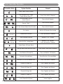
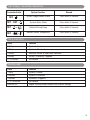
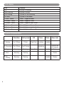
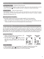
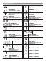
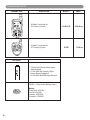
Owner’s
Manual
Model: X11
For Technical Assistance, please call (800) 638-3600,
or visit www.magnadyne.com
Table of Contents
Introduction . . . . . . . . . . . . . . . . . . . . . . . . . . . . . . . . . . . . . . . . . . . . . . . . . . . . . . . . . . . . . 3
Remote Control Transmitters . . . . . . . . . . . . . . . . . . . . . . . . . . . . . . . . . . . . . . . . . . . . . . . . 3
Battery Replacement . . . . . . . . . . . . . . . . . . . . . . . . . . . . . . . . . . . . . . . . . . . . . . . . . . . . . . 3
2
Quick Reference
LCD Transmitter Operation . . . . . . . . . . . . . . . . . . . . . . . . . . . . . . . . . . . . . . . . . . . . . . .
Chirp Indicators . . . . . . . . . . . . . . . . . . . . . . . . . . . . . . . . . . . . . . . . . . . . . . . . . . . . . . .
Parking Light Indicators . . . . . . . . . . . . . . . . . . . . . . . . . . . . . . . . . . . . . . . . . . . . . . . . .
LED Display . . . . . . . . . . . . . . . . . . . . . . . . . . . . . . . . . . . . . . . . . . . . . . . . . . . . . . . . . .
System Characteristics . . . . . . . . . . . . . . . . . . . . . . . . . . . . . . . . . . . . . . . . . . . . . . . . . .
4-5
5
5
6
6
Security Operation
Active Arming: Lock and Arm . . . . . . . . . . . . . . . . . . . . . . . . . . . . . . . . . . . . . . . . . . . . .
Manual Disarming: Unlock and Disarm . . . . . . . . . . . . . . . . . . . . . . . . . . . . . . . . . . . . .
Remote Valet Mode . . . . . . . . . . . . . . . . . . . . . . . . . . . . . . . . . . . . . . . . . . . . . . . . . . . .
Remote Vehicle Locator System . . . . . . . . . . . . . . . . . . . . . . . . . . . . . . . . . . . . . . . . . . .
Panic Function . . . . . . . . . . . . . . . . . . . . . . . . . . . . . . . . . . . . . . . . . . . . . . . . . . . . . . . .
Trigger the System . . . . . . . . . . . . . . . . . . . . . . . . . . . . . . . . . . . . . . . . . . . . . . . . . . . . .
Anti-Car Jacking . . . . . . . . . . . . . . . . . . . . . . . . . . . . . . . . . . . . . . . . . . . . . . . . . . . . . . .
System Status Check . . . . . . . . . . . . . . . . . . . . . . . . . . . . . . . . . . . . . . . . . . . . . . . . . . .
Driver LCD Transmitter Paging . . . . . . . . . . . . . . . . . . . . . . . . . . . . . . . . . . . . . . . . . . . .
Dome Light Supervision . . . . . . . . . . . . . . . . . . . . . . . . . . . . . . . . . . . . . . . . . . . . . . . . .
Ignition Controlled Door Locks . . . . . . . . . . . . . . . . . . . . . . . . . . . . . . . . . . . . . . . . . . . .
Channel 3 Trunk Release Output . . . . . . . . . . . . . . . . . . . . . . . . . . . . . . . . . . . . . . . . . . .
Channel 4 Output . . . . . . . . . . . . . . . . . . . . . . . . . . . . . . . . . . . . . . . . . . . . . . . . . . . . . .
Channel 5 Output . . . . . . . . . . . . . . . . . . . . . . . . . . . . . . . . . . . . . . . . . . . . . . . . . . . . . .
Channel 6 Output . . . . . . . . . . . . . . . . . . . . . . . . . . . . . . . . . . . . . . . . . . . . . . . . . . . . . .
Channel 7 Output . . . . . . . . . . . . . . . . . . . . . . . . . . . . . . . . . . . . . . . . . . . . . . . . . . . . . .
7
8-9
9
10
10
10-11
11-12
12
13
13
13
13
13
14
14
14
Remote Starter Operation
User Warnings . . . . . . . . . . . . . . . . . . . . . . . . . . . . . . . . . . . . . . . . . . . . . . . . . . . . . . . .
How to Remote Start Your Vehicle . . . . . . . . . . . . . . . . . . . . . . . . . . . . . . . . . . . . . . . . .
How to Operate the Vehicle While Running on Remote Start . . . . . . . . . . . . . . . . . . . . .
Quick Stop Operation . . . . . . . . . . . . . . . . . . . . . . . . . . . . . . . . . . . . . . . . . . . . . . . . . . .
Timer Starting Modes . . . . . . . . . . . . . . . . . . . . . . . . . . . . . . . . . . . . . . . . . . . . . . . . . . .
Turn Off Remote Start . . . . . . . . . . . . . . . . . . . . . . . . . . . . . . . . . . . . . . . . . . . . . . . . . . .
Shut Down Input for Remote Starter . . . . . . . . . . . . . . . . . . . . . . . . . . . . . . . . . . . . . . .
Turbo Timer Mode . . . . . . . . . . . . . . . . . . . . . . . . . . . . . . . . . . . . . . . . . . . . . . . . . . . . .
15
15
15
16
16
17
17
17
Remote LCD Icons . . . . . . . . . . . . . . . . . . . . . . . . . . . . . . . . . . . . . . . . . . . . . . . . . . . . . . .
Programming the LCD Transmitter . . . . . . . . . . . . . . . . . . . . . . . . . . . . . . . . . . . . . . . . . . .
Timer Setting . . . . . . . . . . . . . . . . . . . . . . . . . . . . . . . . . . . . . . . . . . . . . . . . . . . . . . . . . . . .
Replacement Parts Order Form . . . . . . . . . . . . . . . . . . . . . . . . . . . . . . . . . . . . . . . . . . . . . .
Warranty . . . . . . . . . . . . . . . . . . . . . . . . . . . . . . . . . . . . . . . . . . . . . . . . . . . . . . . . . . . . . . .
18
19-20
21
22-23
24
Introduction
Congratulations on your purchase of a quality Marksman automotive security and remote start
system. Marksman security products have been designed to provide the consumer with a
technologically superior product with years of trouble free operation. The information enclosed will
provide a ready reference of the operation and maintenance of your new Marksman security and
remote start system.
Remote Control Transmitters
The LCD screen on the remote control displays graphic icons. It provides you visual information on
any trigger of the sensors and around the clock surveillance to your vehicle as well as showing the
present status of the system.
2-Way
LCD
Remote
IGN
TRUNK
HOOD
ARM
LCD
Display
Icons
1-Way
Backup
Remote
Battery Replacement
The two-way LCD remote control is powered by a 1.5V type AAA high power digital camera battery.
When the power of the battery weakens 3 things will happen to indicate a low battery.
1. All the LCD icons on the display will turn off and only the battery icon
will be flashing.
2. The two-way reporting function will turn off to preserve remaining battery power until a
replacement battery is installed.
3. When the buttons on the transmitter are pressed you will hear 3 beeps.
When the old battery is replaced with a new one, there will be a melody playing to indicate the
power is up and the clock on the LCD screen returns to AM12:00 after displaying all the icons.
Correct the time by pressing SET for 3 seconds before using.
Note: Even if the battery is replaced, your programmed set values shall remain unchanged. The
remote control automatically reads and memorizes all the previous set information saved in the
main control module.
Press the
button two times
when the battery compartment
is empty, then insert the new
battery.
3
LCD Transmitter Operation
Transmitter Button
System Function
Remark
Locks Doors & Arms System
-
Arm and Bypass the 2 Stage
Shock Sensor (Zone 4)
Press Twice within 3 Seconds
-
Arm and Bypass the 2nd
Sensor (Zone 6)
Press within 5 Seconds
Arm and Bypass
Sensor 1 and 2
Press within 5 Seconds
Arm and Activate Hidden Alarm Function
Press within 3 Seconds
Car Locator
Wait for 30 Seconds After Arming
Remote Panic Function
Press and Hold for 3 Seconds
Silent Arming/Disarming
Ignition in “OFF” Position
Active Anti-Car Jacking Mode
Ignition in “ON” Position,
Press and Hold for 2 Seconds
-
-
Hold for 3
Seconds
+
Hold for 2
Seconds
+
Unlock Doors & Disarm Alarm
-
Two Step Door Unlock &Disarm Alarm
Press Unlock Twice within 3 Seconds
Trunk Release (Channel #3)
Press and Hold for 1.5 Seconds
-
Automatic Arming Bypass
Alarm Must be in Disarmed Mode
-
Activate or Turn Off the Remote Start
Press Twice within 3 Seconds
+
Channel #4 Output (4)
Press Together and Release
+
Channel #5 Output (5)
Press Together and Release
Channel #6 Output (6)
Press Together and Release
Channel #7 Output (7)
Press Together and Release
Switch Transmitter Operation
to the Second Car/System
Press and Release trunk, Then press LockUnlock Together
+
+
4
+
LCD Display Transmitter Operations
Transmitter Button
SET SET - SET SET -
=
SET -
=
System Function
Remark
System Trigger Record Check
Press within 3 Seconds
System Status Check
Press within 3 Seconds
Optional Driving Pager
Press within 3 Seconds
Monitor Interior Temperature
Press within 3 Seconds
Chirp Indicators
Chirp
Function
1 Chirp
System is Armed
2 Chirps
System is Disarmed
3 Chirps
Defective Sensor of Open Door Reminder
4 Chirps
Disarm / Previously Triggered
2, 3, 6 Chirps
Car Locator
Parking Light
Flash
Function
1 Flash
System is Armed
2 Flashes
System is Disarmed
3 Flashes
Disarmed / Triggered
2 - 3 - 6 Flashes
Car Locator
Constant On
Engine Running Under Remote Start (Default Setting)
5
LED Display
LED
Function
OFF
System is Disarmed
Slow Flashing
System is Armed
Fast Flashing
System in Passive Arming
On Solid
System in Valet Mode
1 Flash - Pause
Zone 1, Trigger for Hood
2 Flashes - Pause
Zone 2, Trigger on Trunk
3 Flashes - Pause
Zone 3, Trigger on Door Switch
4 Flashes - Pause
Zone 4, Trigger on Sensor #1
5 Flashes - Pause
Zone 5, Trigger on Ignition Switch
6 Flashes - Pause
Zone 6, Trigger on Sensor #2
System Characteristics
1. Arming
Siren/Horn
Parking Light
LED
Doors
Starter
1 or 3 Chirps
1 Flash
Slow Flash
Locking
Disabled
2. Disarming 2 to 4 Chirps
6
2 or 3 Flashes
3. Trigger
Alarming
Flashing
4. Panic
Alarming
Flashing
5.Car
Jacking
Alarming
Flashing
Turns on for
30 Seconds
Unlocking
Pause Flash
Dome Light
Disabled
Flashes
Flashes
Disabled
Flashes
Manual Arming: Lock and Arm
1. Press the
button on the transmitter.
2. The siren will chirp once and parking lights will flash once indicating that the system is now
armed. The vehicle door will lock upon arming when interfaced with the security system.
ARM
Trunk/Hood Ajar
ARM
HOOD
ARM
Door Ajar
TRUNK
System Armed
Clear the Flash Icon:
Press the SET button 3 times
within 3 seconds to clear the
flash icon on the LCD screen
transmitter.
Door Ajar / Defective Sensor Reminder
If the siren sounds 3 times, there is a Door, Trunk, or Hood left open.
Silent Arming/Disarming
Pressing the transmitter
and
button at the same time will arm or disarm your security
system, No chirp sound will be heard, arm/disarm confirmation will be through the vehicles
parking lights only.
Shock Sensor Bypass (Sensor #1)
Press the button on the transmitter two times within 3 seconds. This will arm the security
system and bypass the shock sensor.
Sensor Bypass (Sensor #2)
Press the button first, within 3 seconds, press the
the security system and bypass the #2 sensor.
button on the transmitter. This will arm
All Sensor Bypass (Sensor #1 and #2)
Press the button first, within 3 seconds, press the
button on the transmitter (2) times. This
will arm the security system and bypass both electronic sensor ports.
Notes on Remote Sensor Bypass: The sensor bypass feature is programmed to activate for one
arming cycle only. The security system will return to normal operation during the next arming cycle.
Automatic Arming (Applies only when Automatic Arming is Programmed On)
This security system is equipped with an optional automatic arming feature which allows the
security system to arm 30 seconds after the last door is closed. Operation is as follows:
1. Turn the ignition to the “OFF” position and exit the vehicle.
2. After all entrances are closed, the security system LED will flash fast for 30 seconds. If you reopen any protected entrance, the security system LED will stop flashing. It will begin flashing
again once the vehicles entrances are closed.
3. After the 30-second timer has elapsed, the security system will automatically “ARM”. The
siren/horn will chirp once and the parking lights will flash once.
7
Automatic Arming: Lock and Arm (continued)
(Additional programming required)
Automatic Arming with Passive Door Locking
The vehicle doors will automatically lock after the automatic arming cycle has been completed.
Automatic Arming Bypass
While the system is in disarmed mode, press the
button twice. The horn/siren will respond
with one chirp and the LED will turn “ON”. The security system will remain in this mode for as
long as you wish. To exit this mode press the or buttons and the system will return to normal
status.
Disarming: Unlock and Disarm
1. Press the button on the transmitter.
2. The siren will chirp twice and parking lights will flash twice indicating that the system is now
disarmed. The vehicle door will unlock and the dome light will turn on for 30 seconds upon
disarming when interfaced with the security system.
Shock Sensor
Triggered
Ignition Triggered
Trunk/Hood Triggered
IGN
TRUNK
Door Triggered
HOOD
System Disarmed
Clear the Flash Icon:
Press the “SET” button 3 times within 3 seconds will
clear the flash icon on the LCD screen transmitter.
Tamper Disarming
If the security system was triggered, upon disarm, the siren will chirp 4 times and parking lights
will flash 3 times.
Pathway Illumination
(Must be Programmed On)
This feature turns the parking lights “ON” for 30 seconds upon a unlock signal and for 10 seconds
upon the lock signal.
8
Disarming: Unlock and Disarm (continued)
Two Steps Door Unlock
(Additional Wiring Required)
This feature will independently unlock the drivers door only when disarming the security
system. Pushing the button a second time within 3 seconds will unlock the other doors.
Automatic Rearm
(Must be Programmed On)
If this feature is selected, the security system will automatically rearm itself within 60 seconds
after disarming with the remote transmitter. Automatic rearm will cancel if any door is opened
before the 60 second timer is up.
Disarming without a Transmitter
The override function may be used if the remote transmitter is lost or inoperative.
1. Enter the vehicle and turn the ignition switch to “ON” position (alarm will sound).
2. Within 10 seconds push and release the valet switch, the alarm will stop sounding and enter
the disarm mode. You can now start and operate the vehicle normally.
Remote Valet Mode (System in Disarm or Valet Mode)
The valet switch allows you to temporarily bypass all alarm functions eliminating the need to hand
your transmitter to parking attendants or garage mechanics. When the system is in valet mode, all
alarm functions and remote start functions are bypassed, however the remote panic feature and
remote door locks will remain operational. To use the valet mode, the system must first be
disarmed either by using your remote transmitter, or by operating the manual override sequence.
Enter the Valet Mode:
Remote Door
Lock
Remote Door
Unlock
HOOD
1. While in disarmed mode, turn the ignition to “Off”
position and open the drivers door.
2. Push and hold the
and
buttons until the
door locks cycle “Lock/Unlock”. The LED will will
flash every 5 seconds while the unit is in the valet
mode.
Exit the Valet Mode:
1. While in disarmed mode, turn the ignition to “Off” position and open the drivers door.
2. Push and hold the
and
buttons until the door locks cycle “Lock/Unlock”.
The LED will will be off indicating the alarm is out of the valet mode.
9
Progressive Remote Vehicle Locator System
Note: The remote vehicle location system is active 30 seconds after the alarm is armed.
1. Press the
button to active the vehicle locator system. The horn/siren will beep 2 times and
the parking lights will flash 3 times. This operation will repeat a second time.
2. Press the
button again within 30 seconds. The horn/siren will beep 3 times and the parking
lights will flash 3 times. This operation will repeat a second time.
3. Press the
button again within 30 seconds. The horn/siren will beep 6 times and the parking
lights will flash 6 times.
Remote Panic Function
The transmitter can be used as a remote panic switch to manually trigger the alarm system in case
of an emergency.
1. Press and hold the
button for 3 seconds. The security system will begin to sound and the
parking lights will begin to flash. The
icon will display in the LCD transmitter display.
2. During panic mode, the normal functions of this transmitter becomes temporarily inoperable.
The transmitter and buttons can be used to lock and unlock the door (if the option is
installed), however, once the button is pressed, the vehicle’s starter disable device, will be
enabled allowing the vehicle to start.
3. To stop the panic alarm, press the
transmitter button , the panic mode will be turned off
immediately.
4. If the
button is not pressed, the alarm will automatically stop after 30 seconds.
Trigger the System
When armed, your vehicle is protected as follows:
1. Light impact will trigger the warn-away signal.
2. Heavy impacts, doors open, hood open, trunk open or ignition key activated will trigger the
programmed sequence. The starter disable relay prevents the vehicle’s starter from cranking.
The siren, horn, parking lights and dome light will turn on to alert of an intrusion for 30
seconds. If one of the sensors or detectors are still active, the security system will sound a
maximum of 6 times for 30 seconds.
ARM
HOOD
ARM
Trunk / Hood
Triggered
10
Warn Away
Triggered
ARM
TRUNK
Doors
Triggered
Shock Sensor
Triggered
ARM
Ignition
Triggered
IGN
Trigger the System (continued)
LCD Transmitter Melody Sound
When the Security System is triggered, it will alert the user with flashing icons on the LCD Display
and audible melody sound. To stop the melody sound, press any button on the LCD transmitter.
LCD Transmitter Clear the Flash Icon and Melody Sound
When the Security System is triggered, the LCD screen will alert the user through melody sound
and flashing icons. By pressing the “SET” button 3 times within 3 seconds it will clear the flashing
icons and stop the melody sound.
Noise Abatement
The X11 security system has a built-in Noise Abatement Circuit that prevents annoying, repetitive
false alarms by filtering out environmental conditions. If the security system is triggered more
than five times by the same sensor , the circuit will interpret this as a false alarm and ignores, or
bypasses that switch or sensor.
The Noise Abatement Circuit monitors doors, hood and trunk switches differently. If the security
system is triggered by one of these switches for three cycles, the switch will be bypassed until the
trigger ceases.
Anti-Car Jacking
Warning: The anti-car jacking feature default setting is “OFF”. Have your installation facility enable
this feature if you feel it is needed.
Manual Anti-Car Jacking
1. Press and hold the transmitter
and
buttons at the same time for 2 seconds while the
vehicle’s ignition is “ON” and all doors are closed. The parking lights will turn on for 1.5
seconds to indicate the anti-car jacking protection is armed.
2. Once the system is armed, if you are forced from your vehicle, the system will trigger when the
door is opened and closed while the ignition is “ON”.
Passive Anti-Car Jacking
1. Close all entrances first then turn the ignition switch to the “ON” position, the anti-car jacking
system will arm.
2. Once the system is armed, if you are forced from your vehicle, the system will trigger when the
door is opened and closed while the ignition is “ON”.
11
Anti-Car Jacking (continued)
Trigger the Anti-Car Jacking Mode
Three Timer circuits will function as follows:
First Timer Circuit
1. 50 seconds after the car jacking mode has been activated, the siren will begin to sound for 15
seconds.
2. During the 15 second activation period, you will be alerted to push the valet switch once to
turn off the car jacking feature.
3. If by now the valet switch has not been pushed, it will enter the second timer circuit.
Second Timer Circuit
65 seconds after the system has been triggered, the siren starts sounding and the parking lights
start flashing.
Third Timer Circuit
90 seconds after the security system has been triggered:
1. The vehicles siren is still sounding, parking light are flashing
2. The starter disable mode will activate to prevent the vehicle from starting
3. It will remain active until the vehicles battery power is exhausted
Override the System to Turn Off Anti-Car Jacking
Turn the ignition switch from OFF to ON and within 10 seconds, push the valet switch. The siren
will stop sounding and the security system is now disarmed.
Status Checking (LCD Transmitter Only)
System Check
When you want to check the security systems present status through the transmitter LCD, press the
transmitter “SET” button twice, within three seconds press the
button. The security system
responds with one melody sound and the LCD screen should be illuminated.
Note: If there is no response from the LCD transmitter, you may be out of range to receive the
signal.
System Trigger Check
HOOD
ARM
12
IGN
TRUNK
Press the transmitter “SET” button first, within three seconds press the
button. The transmitter will respond with one melody sound and all
trigger records will immediately displayed on the transmitter LCD screen.
Driver LCD Transmitter Paging
It is useful in the event that someone wants to page the driver of the parked vehicle. (Optional)
Inside the Vehicle Paging
With the ignition switch in the "OFF" position, press the valet switch for 2 seconds to page the
driver. One chirp will sound from the vehicle and the LCD transmitter will begin to sound with a
melody. The
icon will then appear on the LCD transmitter to confirm this function.
Outside the Vehicle Paging (Optional and Requires Glass Mount Knock Sensor)
To page the drive of the vehicle, "Knock" on the windshield glass to activate the LCD transmitter
with a melody sound. The
icon will then appear on the LCD screen (only when the optional
knock sensor, Model # M10-Page, is installed).
1. Turn on the vehicle paging sensor. Press the SET button on the LCD transmitter, within 3
seconds, press the
button to activate the driver paging sensor. The vehicle will then
respond with chirps from the horn/siren and a melody sound from the LCD transmitter. The
icon will then appear on the LCD transmitter screen.
2. When the windshield knock sensor is activated, the vehicle will then respond with chirps from
the horn/siren and a melody sound from the LCD transmitter. The
icon will then appear on
the LCD transmitter screen.
3. When the driver of the vehicle unlocks the doors using the remote, the driver paging system
will turn off.
Dome Light Supervision
The Security System has a unique feature which will control your vehicle’s dome light.
1. Upon disarming the vehicle security system, the interior dome light will come on and remain
remain on for thirty seconds.
2. When the vehicle security system is triggered, the dome light will flash for the same duration
as the horn/siren pulses.
Ignition Controlled Door Locks
If the vehicles door locks have been interfaced with the security system, the system will
automatically lock the vehicle’s doors when the ignition key is turned to the “ON” position and or
unlock the doors when ignition key is turned to the “OFF” position. The doors must be closed.
Channel 3: Trunk Release Output
Press and hold the
button for 1.5 seconds to activate the trunk release (Channel 3 output)
and/or any other devices connected.
Channel 4 Output
Press and hold the
and
button at the same time to activate the Channel 4 output.
13
Channel 5 Output
Press and hold the
and
button at the same time to activate the Channel 5 output.
Channel 6 Output
Press and hold the
and
button at the same time to activate the Channel 6 output.
Channel 7 Output: (Default Setting = Defrost Control)
Press and hold the
and
button at the same time to activate the Channel 7 output.
Note: If Channel 7 has been programmed for defrost operation it will not function from the transmitter.
14
Remote Start Operation
User Warnings
As with any product that performs automatic functions, there are certain safety precautions that
you must practice and be aware of.
1. Keep the transmitter out of reach of children.
2. DO NOT leave anyone in the vehicle while running on remote control.
3. Alert any service personal that the vehicle can be started automatically.
4. DO NOT start the vehicle by remote while it’s in an enclosed area or garage.
5. Always apply the parking brake and lock the vehicle as you exit the vehicle.
6. Should the unit malfunction, disconnect the fuse until the problem is corrected.
7. The use and operations of this security system is the sole responsibility of the
owner/operator of the vehicle.
8. Some areas may have local ordinances that prohibit leaving a vehicle running on public
streets. Check your local laws and ordinances.
To Remote Start Your Vehicle by Using the Remote Transmitter
1. Press the
button twice on the remote transmitter.
2. The parking lights will turn “ON” to indicate the remote start command has been received.
3. The engine will start in approximately 5 seconds.
4. Once the engine is running, the parking lights will turn back on to indicate climate controls are
activated to your presettings (While the vehicle is running, the “minute” digits will appear
flashing on the LCD screen of the transmitter. It will indicate the count down timer based on
the 5, 10, 20 or 30 minute run time set up by your installation center).
5. The vehicle will run for 5 to 30 minute cycles and automatically shut down (When the unit
shuts off the count down timer will turn off and the transmitter will play a melody tune).
Note: The Remote Start unit will not start if any of these conditions exist:
1. The hood is opened.
2. The brake pedal is pressed.
3. Move the optional remote start enable toggle switch to “OFF” position (if installed).
4. The gear selector is in any gear other than “Park” or “Neutral”.
Safe Start (Child Safety Mode):
The factory default setting to remote start your vehicle is to press the button twice. If the child
safety mode has been activated, press the
and the
buttons at the same time to remote start
the vehicle.
To Operate the Vehicle While in the Remote Start Feature
1. Insert the Ignition key, turn it to the “ON” position “NOT THE START POSITION”.
2. Press the brake pedal.
Note: If the Brake Pedal is pressed before the key is in the “ON” position, the engine will
automatically shut off.
15
Remote Start Operation (continued)
Quick Stop Feature
This feature allows the vehicle to remain running after the key has been removed from the
ignition. This feature is useful for occasions when you wish to exit and lock/arm the vehicle for
short periods of time. This will keep the engine running for climate controls to stay on.
1. Before turning the engine off with the ignition key, press the
button twice. The LED will flash
three times to indicate the feature is activated.
2. Turn the ignition key to the “OFF” position (the engine will stay running).
3. The engine will run until the pre-programmed run time elapsed or a shutdown input is
received.
Timer Starting Modes
The X11 can be programmed to start and run the engine every 3, 2 or 1 hours by time or by
temperature. The X11 can also be set to punctually start the engine at the same time the next day.
In all modes, the engine will run for the pre-set time (Default setting is 10 minutes) running time
and then shut down the same as if it were being controlled by the remote transmitter.
Important! Timer starting should be used only in open areas. Never start, or most importantly
leave a vehicle running in an enclosed area.
3, 2 or 1 Hour Timer Start without Temperature Control: (Default Setting is 3 Hours)
This feature is designed for extreme cold climate usage. The system will auto start the vehicle
every three hours to prevent the engine from freezing and creating a hard-to-start condition.
3, 2 or 1 Hour Temperature Starting Control: (Default Setting is 3 Hours)
The system can be programmed to automatically start the vehicle’s engine whenever the
temperature inside the vehicle reaches and/or drops below a preprogrammed temperature level.
The X11 system will check the interior temperature ever 3,2 or 1 hour.
Hourly Timer Start: (Runs Every 3, 2, or 1 Hours Depending on Programming)
Press the button first, within three seconds press the
button. The parking lights will flash
six times and the siren/horn will sound six times. The vehicle is now in timer start mode.
Note: The hourly timer start function requires additional programming of the LCD remote
transmitter. (See Timer Setting page 20 for programming).
Daily Timer Start:
Press the button first, within three seconds press and hold the
button for 3 seconds. The
parking lights will flash six times and the siren/horn will sound six times. The vehicle is now
programmed to start at the same time tomorrow (next day).
Note: The daily timer start function requires additional programming of the LCD remote
transmitter. (See Timer Setting page 20 for programming).
Exit the Timer Start:
To Cancel the timer start function, do one of the following:
1. Start the vehicle manually using the ignition key.
2. Remote start the vehicle using your remote transmitter.
16
Turn Off Remote Start
When the engine is running by remote start and you wish to stop the engine from running:
1. Press the
button twice on the remote transmitter.
2. Move the optional remote start toggle switch to the “OFF” position (if installed).
3. Press the vehicle’s brake pedal, the engine will stop running and the parking lights turn off to
indicate the engine has stopped.
Shut Down Input for Remote Starter
If any of the following conditions exist while the system is operating, the engine will not start or will
shut down immediately:
1. The hood is opened.
2. The brake pedal is pressed.
3. The hand brake is released (for Standard Transmission vehicles only).
4. Engine is over-RPM (Tachometer Checking Type only).
5. The preprogrammed run time (5/10/20/30 minutes) has elapsed.
6. Press the
button twice on the remote transmitter under Remote Start Mode.
7. Move the optional remote start enable toggle switch to “OFF” position (if installed).
8. The vehicle refused to start running after 3 unsuccessful attempts.
Turbo Timer Mode (Also See Installation Manual)
Turbo Timer Mode keeps the engine running after arriving at you destination for a programmable
time period of 3, 5 or 10 minutes. This allows the system’s time to conveniently cool down the
turbo charger after you have left the vehicle.
To Activate:
1. While the engine is running, set the emergency brake and place the transmission to "Park".
2. Before turning off the engine, press and release
and
buttons at the same time. The light
will flash to indicate the remote start has entered Turbo Timer Mode.
3. Remove the ignition key from the key cylinder. The engine will keep running.
4. Exit and secure the vehicle. The engine continues running until the preprogrammed time has
elapsed.
Interference
Note: The transmission range may become shorter if the system is interfered by a stronger radio
frequency from sources of high voltage electric power or obstacles like tall buildings. The
transmitter uses low output powered frequency.
17
Remote LCD Icons
Armed Mode
Vehicle is in armed mode
Car Jack Mode
Car jacking mode is activated
Remote Transmission
You are transmitting the signal to
the control unit
In-Range Indicator
You are within the remote
control range
Hood Trigger
Hood is illegally opened (Zone 1)
Sensor Trigger
Trigger on sensor 1 (zone 4) or
optional sensor 2 (zone 6)
Trunk Trigger
Trunk is illegally opened (Zone 2)
Warn Away Trigger
Warn away trigger on sensor 1
or optional sensor 2
Door Open Warning
Doors are illegally opened
(Zone 3)
Low Battery
You have to replace the remote
controls battery
Ignition Trigger
Ignition switch is illegally turned
on (Zone 5)
Engine Running
Your vehicle’s engine is running
System Trigger
Alarm Alert
You have set morning
alarm call
Engine Cranking
Your vehicle’s engine is cranking
by remote control
Power Save Mode
Saves the battery power
Timer Control Start
Engine start automatically at the
same time next day or 2/3 hours.
Vibration Mode
Remote control vibrates when
the system is triggered
Time Monitor
Driver Paging
Someone is paging you in front
of your vehicle
Count Down Timer
Reminder when time
is up for parking
Channel #3 is Activated
Melody Mode
Remote control alert user
through melody sound
18
Hidden Alarm Mode
Your vehicle is in armed with
hidden alarm mode
Valet Mode
All the function shall be
temporarily on hold
Channel #4 is Activated
Channel #5 is Activated
Button Lock
Disable the transmission
function temporarily
Channel #6 is Activated
Temperature Monitor
Indoor temperature of your
vehicle
Channel #7 is Activated
Programming the LCD Transmitter
Button
Description
Operation
SET
LCD Screen Lamp Turns ON for
Five Seconds
Press and Hold for 1 Second
1 Melody Sounds to Confirm
SET
Timer Programming Mode
Press and Hold for 3 Seconds
2 Melody Sounds to Confirm
SET
Power Save Mode
Press and Hold for 5 Seconds
1 Melody Sounds to Confirm
SET (3X)
Clear the Flash Icon and Melody Sound
on the LCD Screen
Press within 3 Seconds
Button Lock Enabled/Disabled
Press within 3 Seconds
Melody/Vibrate Mode
Press within 3 Seconds
SET +
Program Count Down Timer
(10 m, 20 m, 30 m, 1 hr, 1.5 hr, 2 hr)
Press within 3 Second Cycles
Leave the Buttons Starting Count
Down then Timer Icon Flashes
SET +
Enable/Disable Beep Sound While
Pressing Button
SET & LOCK
SET & UNLOCK
SET - SET SET -
+
Display Illumination On/Off
Press for 2 Seconds
3 Seconds between “SET - SET”
and Hold
for 2 Seconds
Switch Between 1st Car RF Control and
Hold
2nd Car RF Control
+
for 2 Seconds
Screen Lamp On
Press and hold the “SET” button one second, with the melody sound and the LCD screen lamp
will turn on for 5 seconds.
Power Save Mode
While in the Power Save Mode, the LCD transmitter uses “0” current to save the battery power.
1. Press and hold the “SET” button for 5 seconds. One melody will sound from the transmitter
and the LCD will show “SAVE”. You are now in the Power Save Mode.
2. Under the Active Arming Mode and Disarm Mode. Turn the ignition switch to the “ON” position.
The LCD remote transmitter will automatically enter the Power Save Mode.
Exit Power Save Mode
Press any button on the LCD transmitter to exit the Power Save Mode.
Clear the Flash Icon and Melody Sound
Press the SET button 3 times within 3 seconds and it will clear the flashing icon and melody
sound on the LCD transmitter.
19
Programming of the LCD Transmitter
Stop the Trigger Melody
While triggering the alarm, the LCD screen will alert the user through melody sound and flashing
trigger icon. Press any button on the transmitter to stop melody sound only.
Button Lock
Use this mode to disable the transmission function of the remote control temporarily to prevent
any inadvertent pressing of buttons.
1. Press the “SET” button first, within 3 seconds press and hold the
button for 2 seconds to
activate or cancel the button lock function. The
icon will be displayed on the LCD screen
to show button lock mode.
Vibration/Melody Mode
This mode is useful when you are in a noisy place and it is difficult to hear the beep from the
remote. The LCD transmitter will vibrate if your security system has been activated.
Press the “SET” button first, within 3 seconds press the ( ) button for 2 seconds to select
the mode of vibrate/melody. The
icon will be displayed on the LCD screen to show mode.
Set-Up Fixed Count Down Timer
Press the “SET” button first, then within 3 seconds press and hold the
button for 2 seconds.
The LCD screen will show the icon and timer (0:10). Press the
button again to choose the
desired time.
Note: 1. The countdown periods are fixed at 10 minutes, 20 minutes, 30 minutes, 1 hour, 1.5
hours and 2 hours maximum.
Note: 2. Press the SET button for a real time indication of the remaining time left.
Note: 3. When the display is showing 0:00, the timer is off
Out of Range Indication
1. If the transmitter is within range, the
icon will display on the LCD screen.
2. If you are out of range, the
icon will disappear from LCD Screen and transmitter will beep 5
times.
20
Clock and Timer Setting
Step
Button
Description
1
Press and Hold SET
Button for 3 Seconds
Time Setting (Hour)
Flash Digit for Adjusting
for (-) and
(+)
2
Press the SET
Button Once
Time Setting (Min.)
Flash Digit for Adjusting
for (-) and
(+)
3
Press the SET
Button Once
Alert Alarm Time Setting (Hour) Flash
Digit for Adjusting
for (-) and
(+)
4
Press the SET
Button Once
Alert Alarm Time Setting (Min.) Flash
Digit for Adjusting
for (-) and
(+)
5
Press the SET
Button Once
Alert Alarm Setting ON/OFF
for (-) and
(+)
6
Press the SET
Button Once
Count Down Timer Setting (Hour) Flash
Digit for Adjusting
(Max 19 Hrs. 59 Min.)
for (-) and
(+)
7
Press the SET
Button Once
Count Down Timer Setting (Min.) Flash
Digit for Adjusting
for (-) and
(+)
8
Press the SET
Button Once
Count Down Timer Setting ON/OFF
10
Press and Hold
Button for 2 Seconds
Flash
Daily Timer Start Timer Setting
/ Icon and Hours for Adjusting
Operation
for (OFF) and
for (-) and
(ON)
(+)
Note: Any adjustment requires starting at the beginning (Step 1) and following the steps until you
reach the one that corresponds with the description/function you want to program.
For instance, if you are trying to set the Alert Alarm Setting ON/OFF (the description that
corresponds with Step 5) you must follow steps 1-5 in order for it to be set.
21
Replacement Parts
TRANSMITTERS
DESCRIPTION
5-Button Transmitter for
X11 Security System
X11RF-LCD
4-Button Transmitter for
X11 Security System
X11RF
BATTERIES
**1.5 Volt AAA Lithium Battery Highly
Recommended
*1.5 Volt AAA High Capacity Digital
Camera Battery Suggested
1.5 Volt AAA Alkaline Battery Minimum
CR2032 - 3 Volt Lithium Battery (2 pcs.)
Models:
Radio Shack: #23-162
Duracell: #DL2032
Eveready: #ECR2032
Panasonic: # CR2032
22
MODEL #
PRICE
$139.95 ea.
59.95 ea.
Parts Order Form
Credit Card or Money Order Only
(Sorry No Cash, C.O.D. or personal checks accepted)
Call: (310) 884-7777 Fax: (310) 637-9542
Mail to: Magnadyne Corporation
ATTN: Consumer Parts Sales
P.O. Box 5365
Carson, CA 90749-5365
SHIP TO: (No P.O. Boxes)
LAST NAME
FIRST NAME
INITIAL
STREET ADDRESS
ADDITIONAL ADDRESS
ADDITIONAL ADDRESS
CITY
STATE
ZIP CODE
DAY TIME PHONE NUMBER
CREDIT CARD INFORMATION
VISA
MC
CREDIT CARD N0.
EXPIRATION DATE
CARD HOLDER’S LAST NAME
FIRST NAME
INITIAL
STREET ADDRESS
CITY
STATE
PART #
DESCRIPTION
Shipping and Handling
Up to $20.00
20.01 to 30.00
30.01 to 45.00
45.01 to 70.00
Over 70.01
$5.00
5.95
6.50
6.95
7.95
QTY.
ZIP CODE
PRICE EACH
TOTAL
Sales Subtotal = ________ . ______
California Residents Add Sales Tax = ________ . ______
Shipping and Handling (See Chart) = ________ . ______
TOTAL = ________ . ______
On regular orders please allow 4-5 weeks for delivery.
Please give a shipping address where this order may be delivered between the hours of 9 am and 5 pm weekdays.
If UPS is unable to deliver, your order will be returned and additional shipping charges will be required.
23
Limited Lifetime Warranty
Magnadyne Corporation or its authorized agents will, for the life of the vehicle and to the original
purchaser, repair, replace or refund the retail sales price of said product or any part thereof, at the
option of the Magnadyne Corporation or its authorized agents, if said product or part is found
defective in materials or workmanship, when properly connected and operating on the correct
power requirements designated for the specific product. This warranty and Magnadyne Corporation
or its authorized agents obligations, hereunder do not apply where the product was: damaged while
in the possession of the consumer, subjected to unreasonable or unintended use, not reasonably
maintained, utilized in commercial or industrial operation, or serviced by anyone other than
Magnadyne Corporation or its authorized agent, or where the warning seal on the product is broken
or the power plugs or wires are detached from the unit. Magnadyne Corporation or any of its
authorized agents do not assume any labor costs for the removal and reinstallation of any product
found to be defective, or the cost of transportation to Magnadyne Corporation or its authorized
agents. Such costs are the sole responsibility of the purchaser.
This warranty does not cover the cabinet, appearance items, normal wear and tear or accessories
used in connection with the product resulting from improper installation, alteration, accident,
misuse, abuse or acts of nature.
This Limited Life Time Warranty applies only to the receiver section of the security system. Neither
the siren, transmitters, wire harness or any accessory item added to or used with a Remote Mobile
security system are covered by this Limited Life Time Warranty. Sirens, transmitters, wire harness
or any accessory item are covered by our standard 12 month limited warranty.
Magnadyne Corporation or its authorized agents shall not be liable to anyone for consequential
or incidental damages or claims that may arise due to failure of product to operate properly
except those accorded by law. Magnadyne's or its authorized agents liability to the repair,
replacement of the product as stated above if all conditions of the warranty are met. No
expressed warranty or implied warranty is given except those set forth herein. Magnadyne does
not warrant or guarantee against break in damage or the theft of the vehicle in part or whole, or
against the loss or damage to the contents of any vehicle in which a security system is installed.
Magnadyne security systems are only a deterrent against possible theft.
This warranty extends only to the original purchaser of the product and for the vehicle in which it
was originally installed. This warranty is not transferable or assignable to any person or vehicle.
Defective merchandise should be returned to the original point of purchase or secondly to
Magnadyne Corporation, 1111 W. Victoria Street, Compton, CA 90220. A return authorization must
be obtained before sending, or merchandise may be refused.
© Copyright 2008 Magnadyne Corporation
X11-UM 3-5-08 Rev. A