1
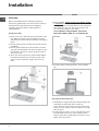
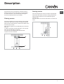
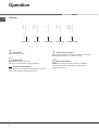
The Art of Cooking
Instructions for Installation and Use
Cooker hood
BHC90
BHC110
To the Installer
Before installation fill in the product details on the back cover this book.
The information can be found on the rating plate.
To the User
You must read the instructions prior to installing and using the appliance and
then retain them for future reference.
1
2
Instructions for use
HOOD
GB
English
Contents
GB
Installation, 4-5
Assembly
Technical information, 6
Electrical connection
Power cable
Technical data
Description, 7
Filtering version
Ducting version
BHC 90
BHC 110
Operation, 8
Controls
Maintenance, 9
Cleaning the hood
Cleaning the grease filters
Replacing the charcoal filter
Replacing the lamps
Precautions and tips, 10
General safety
Air vent
Disposal
3
Installation
GB
Assembly
Before proceeding with the assembly operations,
remove the grease filters so that the hood is easier to
handle (for the instructions see the paragraph
“Cleaning the grease filters” in the chapter on
“Maintenance”).
Fixing to the wall
5) Once adjusted, finally fix the hood with a further
6 screws (D): Mark the 6 holes to be drilled on the
wall, unhook the hood and drill the holes marked (8
mm diameter); then use the screw anchors and
the screws provided for final fixing.
FOR CORRECT FUNCTIONING, THE HOOD
MUST BE FIXED USING ALL 6 SCREWS (D)!
1) Draw a line on the wall along the vertical axis of the
hob. Mark the 2 holes (A) to be made in the wall
respecting the measurements indicated in the figure
below.
2) Drill the holes (8 mm ø) and fit the 2 screw anchors
(provided).
3) Fix the metal bracket (B) to the wall with 2 screws
using the 2 holes drilled. Use the 2 triangles cut into
the bracket to position it exactly along the vertical
axis of the hood.
4) Then hook the hood onto the metal bracket.Adjust
the horizontal position by moving the hood to the
right or left as required to align it with the wall
units.
6) For the hoods in filtering version, fit the reducer
(E).
Securing the decorative flue
1) Assemble the support bracket of the decorative flue
and adjust the width with the 2 screws (F).
Then, using the screw anchors and the screws (G),
secure it to the ceiling in such a way that it is in line
with the hood.
2) For the filtering version, the air vent grilles (H) must
be positioned at the top. For the ducting version,
turn the upper flue upside down so that the air vent
grilles are at the bottom.
4
GB
3) Ducting version:
a) Connect the air vent of the hood to the air vent
hole using a flexible hose of 15 cm diameter.
Lock the flexible hose with hose clamps (hose
and clamps not provided).
b) Make the electrical connection of the hood by
means of the power cable (refer to the paragraph
“Electrical connection”).
c) Fit the decorative flue resting it on the hood. Lift
the upper flue up to the ceiling and secure it by
means of the 2 screws (L).
d) Make the electrical connection of the hood by
means of the power cable (refer to the paragraph
“Electrical connection”).
e) Lower the lower flue resting it on the hood.
f) Check if the charcoal filter (P) has been
installed. If not yet installed, proceed by sliding
the 2 filter clips into their seats and turn the
filter upwards.
4) Filtering version:
a) Fit the baffle (M) to the upper flue using 4 flatheaded screws (N). Connect a flexible hose of
12.5 cm diameter to the baffle locking it with a
hose clamp (hose and clamp not provided).
b) Take the decorative flue and rest it on the hood.
Lift the upper flue up to the ceilingand secure it
using the 2 screws (L).
c) Lift the lower flue holding it firm with some
adhesive tape and connect the flexible hose to
the reducer (E) with a hose clamp (not provided).
5
Technical information
GB
Electrical connection
Power cable
!
!
!
!
!
Arrange the electrical power supply within the
decorative flue dimensions.
When making the electrical connections, check that
the voltage values correspond to those indicated on
the data plate inside the appliance itself.
In case your appliance is not furnished with a non
separating flexible cable and has no plug, or has not
got any other device ensuring omnipolar
disconnection from the electricity main, with a
contact opening distance of at least 3 mm, such
separating device ensuring disconnection from the
main must be included in the fixed installation.
If your unit features a power lead and plug, position
this so the plug is accessible.
Warning: The hood is fitted with a specially
prepared cable; if the cable is damaged, it must
be replaced with a cable or special cable
assembly, available at the manufacturer or its
technical service.
Technical data
6
Model
BHC90
BHC110
Dimensions
width 89.8 cm
height 83 / 125 cm
depth 49 cm
Outlet pipe diameter 15 cm
width 109.8 cm
height 83 / 125 cm
depth 49 cm
Outlet pipe diameter 15 cm
Gross weight
24.5 Kg
29.2 Kg
Absorption
Total 410 W
Motor 1x370 W
Lamps 2x20 W
Total 410 W
Motor 1x370 W
Lamps 2x20 W
Flow rate
625 m3/h
625 m3/h
Grease filters
Suction
surface area
461 cm2
544 cm2
Description
The hood may be in the filtering or ducting version.
Decide from the outset which type is to be installed.
For better efficiency, we recommend installing the
hood in the ducting version (if possible).
Filtering version
Ducting version
GB
The hood aspirates air from the kitchen impregnated
with fumes and smells, passes it through the grease
filters and then expels it to the outside through an
exhaust duct.
For this version the charcoal filter does not need to be
used.
The hood aspirates air from the kitchen impregnated
with fumes and smells, purifies it through the grease
filters and the charcoal filter, and then circulates clean
air back into the room.
This version requires an air baffle (M) and a charcoal
filter (P).
In order to maintain constant efficiency, the charcoal
filter must periodically be replaced.
If the hood is not fitted with the charcoal filter,
request one from the dealer.
M
P
7
Operation
GB
Controls
LIGHTING
MOTOR
DECREASE
Light button
Turns the lights on/off.
Motor button
Activates/deactivates the motor.
The motor is activated at the last speed set.
Speed decrease button
Repeatedly pressing the button will reduce the motor
speed until reaching the minimum speed.
8
INCREASE
BOOST SPEED
Speed increase button
Repeatedly pressing the button will increase the motor
speed until reaching the maximum speed.
Boost speed button
Activates the motor at boost speed for 10 minutes,
after which the motor goes back to running at the
speed set previously.
Maintenance
!
!
Always switch off the electricity supply before
carrying out any cleaning or servicing operations on
the appliance.
To avoid possible risks of fire always comply with
the indicated instructions when cleaning grease
filters and when removing grease deposits from the
appliance.
Replacing the charcoal filter
GB
If using the hood in the filtering version, the charcoal
filter (P) will periodically have to be replaced.
First of all, turn the panel and remove the metal
grease filters. Push the catch towards the inside and
remove the charcoal filter from its seat.
Careful maintenance will assure good functioning and
good efficiency over time.
Cleaning the hood
Any fat deposits should be removed from the appliance
periodically depending on amount of use (at least every
2 months). Avoid using abrasive or corrosive products.
To clean painted appliances on the outside, use a cloth
dipped in lukewarm water and neutral detergent. To
clean steel, copper or brass appliances on the outside,
it is always best to use specific products, following the
instructions on the products themselves. To clean the
inside of the appliance, use a cloth (or brush) dipped in
denatured ethyl alcohol.
Cleaning the grease filters
To remove the grease filters, turn the panel by gripping
it from the front part of the hood; remove the grease
filters by pushing the catch towards the rear of the hood
and turning the filters outwards.
Replace the charcoal filter with one of the same type
by carrying out the operations in reverse order.
Replace the charcoal filter on average every 6 months
depending on how heavily the hood is used.
Replacing the lamps
Pay particular ATTENTION when carrying out
this operation and remember to remove the voltage.
To replace the halogen lamps, open the cover
by prising in the slots. Replace with lamps
of the same type.
WARNING: Do not touch the new lamp with bare
hands.
Wash the filters by hand or in the dishwasher using
a neutral detergent. If they are washed
in the dishwasher, any loss of colour will
not jeopardise functioning of the filters in any way.
Clean the grease filters every 2 months on average
depending on how heavily the hood is used.
9
Precautions and tips
GB
General safety
!
!
!
!
!
!
The distance between the supporting surface for
the cooking vessels on the hob and the lower part
of the hood must be at least 65 cm.
If the instructions for installation for the hob specify
a greater distance, this has to be taken into account.
ATTENTION: This appliance must be grounded.
When making the electrical connection, ensure
that the power outlet is earthed.
When making the electrical connections, check
that the current socket has a ground connection.
Avoid using materials which could cause spurts
of flame (flambées) near the appliance.
When frying, take particular care to prevent oil
and grease from catching fire. Already used oil
is especially dangerous in this respect.
Do not use uncovered electric grates.
Do not place weights above the hood.
Air vent
Should you install the ducting version, prepare the air
vent hole and duct.
In the Ducting version, to get optimal conditions the air
venting pipe should: be as short as possible, have the
lowest number of bends (max bende angle: 90°, be
made of material approved by local authorities
(according to the State), have its inner side as regular
and smooth as possible. It is moreover recommended
to avoid drastic changes of pipe cross section
(recommended diameter: 150 mm).
! The air collected must not be conveyed into a duct
used to blow off smokes from appliances fed with
an energy other than electricity (central heating
systems, thermosiphons, water-heaters, etc.).
! Comply with the official instructions provided by
the competent authorities in merit when installing
the disposal duct. In addition, exhaust air should
not be discharged into a wall cavity, unless
the cavity is designed for that purpose.
! The room must be well aerated in case a hood
and some other heat equipment fed with an energy
other than electricity (gas, oil, coal heaters, etc)
operate at the same time. In fact the ducting hood,
disposing of air, could create a vacuum in the room.
The vacuum should not exceed 0,04mbar.
This prevents the gas exhausted by the heat source
from being intaken again. It is therefore advisable
to ensure the room contains air taps able to ensure
a steady flow of fresh air.
10
Disposal
The European Directive 2002/96/EC on Waste
Electrical and Electronic Equipment (WEEE), requires
that old household electrical appliances must
not be disposed of in the normal unsorted municipal
waste stream.
Old appliances must be collected separately in order
to optimise the recovery and recycling of the materials
they contain and reduce the impact on human health
and the environment.
The crossed out “wheeled bin” symbol on the product
reminds you of your obligation, that when you dispose
of the appliance it must be separately collected.
Consumers should contact their local authority or
retailer for information concerning the correct disposal
of their old appliance.
11
Key Contacts
After Sales Service
Over 1200 trained specialists, directly employed by us, ensure that you can have complete confidence in
both the appliances and services we offer.
Repair Service and Information Desk
UK: 08709 066 066
(Open 8 to 8 Mon - Fri, 8 to 6 Sat, 10 to 4 Sun & Bank Holidays)
www.cannonservice.co.uk
Republic of Ireland: 1850 302 200
Note: Our operators will require the following information:
Model number:
Serial number:
Extended Warranties
UK: 08709 088 088
(Open 8 to 8 Mon - Sun)
www.cannonservice.co.uk
Republic of Ireland: 1850 502 200
Genuine Parts and Accessories
UK: 08709 077 077
(Open 8-30 to 5-30 Mon - Fri & 9 to 12 Sat)
www.cannonservice.co.uk
Republic of Ireland: (01) 842 6836
www.cannoncooking.co.uk
Indesit Company UK LTD, Morley Way, Peterborough, PE2 9JB.
12
04307910