1
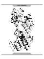
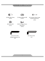
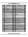
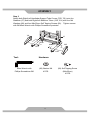
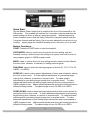
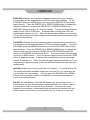
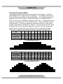
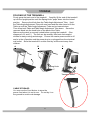
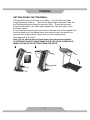
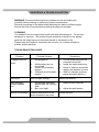
Treadmill OWNER’S MANUAL Item #1030 TABLE OF CONTENTS SERVICE ------------------------------------------------------------------------ 2 IMPORTANT LABELS -------------------------------------------------------- 3 PRODUCT SAFETY ---------------------------------------------------------- 4 PART DRAWING -------------------------------------------------------------- 8 HARDWARE PACKING LIST & TOOLS --------------------------------- 9 PART LIST ---------------------------------------------------------------------- 10 ASSEMBLY --------------------------------------------------------------------- 12 COMPUTER -------------------------------------------------------------------- 16 ADJUSTMENT ----------------------------------------------------------------- 22 STORAGE ----------------------------------------------------------------------- 23 MAINTENANCE & TROUBLE SHOOTING ----------------------------- 25 BELT ADJUSTMENT & LUBRICATION ---------------------------------- 26 WARM UP ----------------------------------------------------------------------- 27 WARRANTY -------------------------------------------------------------------- 28 FAX FORM ---------------------------------------------------------------------- 29 1 SERVICE IMPORTANT: FOR NORTH AMERICA ONLY To request product service and order replacement parts, please call our customer service department at: 1-866-924-1688 Monday through Friday, 8:00 AM-5:00 PM Pacific Standard Time, or email us at: [email protected] Please visit our website at www.paradigmhw.com. Please have the following information ready when requesting for service: Your name Phone number Model number Serial number Part number Proof of Purchase *Before returning this product to the store please contact customer service at the number above. Paradigm Health & Wellness, Inc. 1189 Jellick Ave, City of Industry, CA 91748, USA 2 IMPORTANT LABELS 3 PRODUCT SAFETY Basic precautions should always be followed, including the following safety instructions when using this treadmill: Read all instructions before using this treadmill. DANGER: To reduce the risk of electric shock, please read the following: Always unplug the treadmill from the electrical outlet immediately after using and before cleaning, assembling, or servicing. NOTE: Failure to follow these instructions may lead to personal injury and cause damage to the treadmill. WARNING: To reduce the risk of burns, fire, electric shock or injury to any persons, please read the following: Never leave the treadmill unattended while plugged in. Disconnect by turning off the master power switch, and unplugging from outlet when not in use and before putting on or taking off parts. Use this appliance only for its intended use as described in this manual. Do not use attachments not recommended by the manufacturer. Never operate this treadmill if it has a damaged cord or plug, or if it is not working properly. If it has been dropped or damaged, or been exposed to water, return the appliance to a service center for examination and repair. Do not attempt any maintenance or adjustments other than those described in this manual. Should any problems arise, discontinue use and consult an Authorized Service Representative. Never operate the appliance with the air openings blocked. Keep the air openings free of lint, hair, and the like. Do not use the treadmill outdoors. Do not pull the treadmill by its power cord or use the cord as a handle. Keep children and pets away from the equipment while in use. This machine is designed for adults only. Close supervision is necessary when this treadmill is used by on, near invalids or disabled persons. Do not operate where aerosol (spray) products are being used or where oxygen is being administered. Keep Dry - do not operate in a wet or moist condition. Save these instructions. Do not operate the treadmill near a blanket. Excessive heating can occur and cause fire, electrical shock, or injury to user. Keep electrical cord away from heated surfaces. Never insert any object into any opening. 4 PRODUCT SAFETY Keep the treadmill on a solid, level surface with the minimum safety area clearance of 6ft x 3ft around the treadmill. Be sure the area around the treadmill remains clear during use and has adequate clearance. This treadmill is for household use only. Only one person should be on the treadmill while in use. Wear comfortable and suitable clothing when using the treadmill. Do not use the treadmill barefoot, in only socks or in sandals. Always wear athletic shoes. Never wear loose clothing because it could run the risk of getting caught in the treadmill. Always hold on to the handrails while using the treadmill. Always make sure the storage latch is in place when folding and moving the treadmill. Do not leave children who are under 12 year-old unsupervised near or on the treadmill. To disconnect, turn all controls to the off position, then remove plug from outlet. This appliance is not intended for use by persons (including children) with reduced physical, sensory or mental capabilities, or lack of experience and knowledge, unless they have been given supervision or instruction concerning use of the appliance by a person responsible for their safety. Children should be supervised to ensure that they do not play with the appliance. Pull up the Safety Tether Key for emergency stop. Reinstall the Safety Tether Key onto the Computer Console. Press the START button to begin exercise again. CAUTION - RISK OF INJURY TO PERSONS - To avoid injury, use extreme caution when stepping onto or off of a moving belt. Read instruction manual before using. CAUTION - RISK OF INJURY TO PERSONS – Place no more than a maximum of 45 lbs worth of weight on the table. CAUTION - RISK OF FIRE OR ELECTRIC SHOCK. Use only 120 V ac, 12 A Max. Maximum Weight Capacity is 400 lbs. Note: It is the obligation of the owner to review and explain these safety precautions to all users of this treadmill. WARNING: Connect the treadmill to a properly grounded outlet only. See grounding instructions. SAVE THESE INSTRUCTIONS . 5 PRODUCT SAFETY GROUNDING INSTRUCTIONS This product must be grounded. If it should malfunction or break down, grounding provides a path of least resistance for electric current, reducing the risk of electric shock. * This treadmill is equipped with a grounded cord and a grounded plug. The plug must be plugged into an appropriate outlet that is properly installed and grounded in accordance with all local codes and ordinances. DANGER: Improper connection of the treadmill grounding conductor can result in the risk of electric shock. Check with a qualified electrician, if you are in doubt as to whether the product is properly grounded. Do not modify the plug provided with the treadmill. If it will not fit your outlet, have a properly grounded outlet installed by a qualified electrician. This product is for use on a nominal 120 volt circuit and has a grounding plug that looks like the plug illustrated in Figure 1. Make sure that the product is connected to an outlet having the same configuration as the plug. No adapter should be used with this product. GROUNDED OUTLET GROUNDING PIN GROUNDED OUTLET BOX Figure 1 This unit must be plugged into a nominal 120 volt outlet which has been grounded. Keep hands clear of all moving parts. Never place hands, feet under the Treadmill while in use. Do not use the treadmill on a carpet that is greater than 1/2 inch in height. Before using the treadmill, check that the belt is aligned and centered on the walking deck and all visible fasteners on the treadmill are sufficiently tightened and secure. 6 PRODUCT SAFETY WARNING: Before beginning any exercise program consult your physician. This is especially important for the persons who are over 35 years old or who have pre-existing health problems. Read all instructions before using any fitness equipment. We assume no responsibility for personal injury or property damage sustained by or through the use of this product. Do not operate this exercise equipment without properly fitted guards, as the moving parts can present a risk of serious injury to young children. CAUTION: Read all instructions carefully before operating this product. Retain this Owner’s Manual for future reference. 7 2 8 7 25 3L 2 4 20 51 48 47 7 3R 20 17 55 49 50L 4 25 7 83 45 99 51 44 6 10 20 73 9 67 50R 46 52 97 43 54 96 95 96 20 73 16 11 53 44 1 20 99 73 9 38 80 12 36 39 56 67 40 42 15 12 13 16 77 18 41 21 37 19 20 14 69 22 91 12 41 11 24 34 23 19 33 20 33 8 34 25 20 35 11 26 63 33 34 34 89 92 33 88 18 89 5 31L 88 76L 58 59 85L 32 73 86 73 20 60 27 98 89 17 87 89 81 29 57 78 88 7 61 13 98 89 86 98 89 20 101100 102 63 73 32 79L 71 28 86 32 20 73 87 66 100 7 28 101 31R 82 72 89 28 88 30 18 73 32 68 32 73 75 73 17 73 32 102 84 93 94 76R 74 79R 65 86 59 64 58 62 7 70 90 5 85R 62 65 7 PART DRAWING HARDWARE PACKING LIST & TOOLS (32) Bolt (M8x16mm) 10 PCS (73) Spring Washer (M8) 10 PCS (88) Washer M4 4 PCS (89) Self Tapping Screw (M4x25mm) 4 PCS Allen Wrench with Phillips Screwdriver 5M 1 PC (86) Hexagon Socket Head Cap Bolt (M6x16mm) 4 PCS Allen Wrench 6M 1 PC 9 PART LIST No. Description Qty No. Description Qty 001 Main Frame Rear Roller Adjustment Bolt 002 (M8x70mm) 003R Rear Right End Cap 1 027 Bolt (M8x60mm) 2 2 028 Adjustable Leveler (M10xØ28x40) 5 1 029 Sensor Cable I (550mm) 1 003L Rear Left End Cap 1 030 Sensor Cable II (1650mm) 1 004 Wheel (Ø50xØ8.2x24t) 2 031R Right Stabilizer Tube (Ø50.8x450) 1 005 Self-Tapping Screw (ST3x20mm) 4 031L Left Stabilizer Tube (Ø50.8x450) 1 006 Nylon Nut (M6) 8 032 Bolt (M8x16mm) 14 007 Self-Tapping Screw (ST4x16mm) 17 033 Nylon Washer (Ø8.2xØ25x2t) 008 Self-Tapping Screw (ST4x50mm) Hexagon Socket Head Cap Bolt (M8x23mm) 4 4 034 4 2 035 Rubber Pad 4 Hexagon Socket Head Cap Bolt (M8x40mm) Hexagon Socket Head Cap Bolt 010 (M10x70mm) 011 Bolt (M4x12mm) 1 036 Motor 1 6 037 Power Control Board 1 012 Nut (M4) 4 038 Lift Motor 1 013 Wire Plug (Ø6x21x10) 2 039 Switch, AC Power 1 014 Power Cord Cap 1 040 Fuse Box 1 015 Motor Cover 1 041 Clock Washer (M4) 2 016 Rectangular End Cap 2 042 Wire for Fuse Box (120mm) 1 017 Bolt (M8x35mm) 3 1 018 Square End Cap (□20) 5 019 Nylon Washer (Ø8.2xØ16x2t) 2 043 Incline Bracket Incline Bracket Wheel 044 (Ø50xØ12.5x15mm) 045 Belt (180J5) 020 Nylon Nut (M8) 14 046 Front Roller (Ø40x599) 1 021 Safety Tube A 1 047 Walking Belt (2140x508x1.6) 1 022 Bushing (F23xF20.3x42) 1 048 Walking Deck (557.6x940x18) 1 023 Spring Knob (Ø8xØ22x71) 1 049 Phillips Trim Head Bolt (M6x33) 8 024 Safety Tube B 1 050R Right Side Rail 1 025 Bolt (M8x40mm) Safety Tube B Square End Cap 026 (□25.4) 3 050L Left Side Rail 1 1 051 Deck Bumper (48x32x5) 6 009 10 2 1 PART LIST No. Description Qty No. Description Qty 052 Bolt (M8x45mm) 1 078 M8 Nut Cap 2 053 Motor Bracket 1 079R Right Table Hinge 1 054 Bolt (M8x12mm) 2 079L Left Table Hinge 1 055 Rear Roller (Ø40x599) Hexagon Socket Head Cap Bolt 056 (M10x45mm) 057 Stabilizer Handlebar End Cap 058 (Ø41xØ28.5x40) 059 Foam Grip (Ø30xØ37x600) 1 080 Binding Wire Plate 20x20x7 5 1 081 Gas Spring 1 1 082 Wire Storage Box 1 2 083 Support Board 1 2 084 Wire Storage Box Cover 1 060 Transport Wheel (Ø8.5xØ50x23) 2 085R Right Handlebar 1 061 Phillips Head Bolt (M5x12) 2 085L Left Handlebar 1 1 086 1 087 Plastic Sleeve 2 1 088 Washer M4 4 065 Plastic Drink Holder 2 089 Self Tapping Screw (M4x25mm) 7 066 Elbow Pad 1 090 Wire Management Grommet 1 067 Spacer 2 091 Power Cord 1 068 Table Angle Adjustment Tube 1 092 Linking Bracket 1 069 Bolt (M4x20mm) 2 093 Electrical Outlet 1 070 Table Angle Adjuster 1 094 Self Tapping Screw (ST4x12mm) 2 071 Safety Tether Key 1 095 Washer (Ø10.5xØ21x1.8) 2 072 Computer 1 096 Nylon Washer (M10) 2 073 Spring Washer (M8) 18 097 1 074 Knob (M6x34) 1 Hexagon Socket Head Cap Bolt (M8x90mm) 098 Cord Anchor 3 075 Handlebar Support Tube Frame Right Handlebar Support Tube 076R Cover Left Handlebar Support Tube 076L Cover Wire for Power Control Board 077 (400mm) 1 099 C Ring 2 1 100 Pulse Extension Wire (500mm) 2 1 101 Control Button Extension Wire 2 Incline Buttons and Hand Pulse Sensor with Wires Speed Buttons and Hand Pulse 063 Sensor with Wires 064 Table 062 1 11 Hexagon Socket Head Cap Bolt (M6x16mm) 8 ASSEMBLY Step 1 Connect the Sensor Cable I (29) from inside the Stabilizer (57) to the Sensor Cable II (30) from inside the right side of the Handlebar Support Tube Frame (75). Then connect the Handlebar Support Tube Frame (75) to the Stabilizer (57) by inserting the Handlebar Support Tube Frame (75) onto the Stabilizer (57), using six M8x16mm Bolts (32) and six M8 Spring Washers (73). Tighten bolts with the 5M Allen Wrench with Phillips Screwdriver provided. IMPORTANT: While sliding the Handlebar Support Tube Frame (75) onto the Stabilizer (57), make sure the cables are installed inside the tube and pay attention not to pinch the cables. 75 73 73 32 32 30 29 57 Tool: Hardware: Allen Wrench with Phillips Screwdriver 5M (32) Bolt (M8x16mm) 6 PCS 12 (73) Spring Washer (M8) 6 PCS ASSEMBLY Step 2 Attach both Right/Left Handlebar Support Tube Covers (76R, 76L) onto the Stabilizer (57) and both Right/Left Stabilizer Tubes (31R, 31L) with four M4 Washers (88) and four M4x25mm Self Tapping Screws (89). Tighten screws with 5M Allen Wrench with Phillips Screwdriver provided. 76L 57 88 89 76R 89 88 31L 31R Tool: Allen Wrench with Phillips Screwdriver 5M Hardware: (88) Washer M4 4 PCS 13 (89) Self Tapping Screw (M4x25mm) 4 PCS ASSEMBLY Step 3 Connect the Incline Buttons and Hand Pulse Sensor with Wires (62) from the Right Handlebar (85R) to the Pulse Extension Wire (100) and Control Button Extension Wire (101) from the right side of the Handlebar Support Tube Frame (75). Then connect the Right Handlebar (85R) to the right side of the Handlebar Support Tube Frame (75) by inserting the Right Handlebar (85R) onto the right side of the Handlebar Support Tube Frame (75), using two M8x16mm Bolts (32) and two M8 Spring Washers (73). Tighten bolts with the 5M Allen Wrench with Phillips Screwdriver provided. Connect the Speed Buttons and Hand Pulse Sensor with Wires (63) from the Left Handlebar (85L) to the Pulse Extension Wire (100) and Control Button Extension Wire (101) from the left side of the Handlebar Support Tube Frame (75). Then connect the Left Handlebar (85L) to the left side of the Handlebar Support Tube Frame (75) by inserting the Left Handlebar (85L) onto the left side of the Handlebar Support Tube Frame (75), using two M8x16mm Bolts (32) and two M8 Spring Washers (73). Tighten bolts with the 5M Allen Wrench with Phillips Screwdriver provided. IMPORTANT: While sliding both Right/Left Handlebars (85R/85L) onto the Handlebar Support Tube Frame (75), make sure the wires are installed inside the tubes and take care not to pinch the wires. 101 100 63 85L 73 32 62 85R 101 100 73 32 75 Tool: Hardware: Allen Wrench with Phillips Screwdriver 5M (32) Bolt (M8x16mm) 4 PCS 14 (73) Spring Washer (M8) 4 PCS ASSEMBLY Step 4 Install both Right/Left Table Hinges (79R/79L) to the right and left sides of the Handlebar Support Tube Frame (75) by sliding both Right/Left Table Hinges (79R/79L) onto the right and left tubes on the sides of the Handlebar Support Tube Frame (75). Then attach the Table (64) onto both Right/Left Table Hinges (79R/79L) with four M6x16mm Hexagon Socket Head Cap Bolts (86). Tighten bolts with the 5M Allen Wrench with Phillips Screwdriver provided. Lift the Table Angle Adjustment Tube (68) up onto the Table Angle Adjuster (70) which is under the Table (64). The angle of the Table (64) can be adjusted. There are 4 levels of incline for the Table (64). Secure the Table (64) in place by tightening the M6x34 Knob (74).Place the Safety Tether Key (71) onto the Computer (72). 64 79L 86 74 Left Table Hinge 71 72 79R 86 75 Right Table Hinge Tool: Hardware: Allen Wrench with Phillips Screwdriver 5M (86) Hexagon Socket Head Cap Bolt (M6x16mm) 4 PCS 15 COMPUTER Quick Start: Flip the Master Power Switch that is located at the front of the treadmill to the ON position. The treadmill will self-test for 2 seconds on startup and then the speed setting will show up after a 2 second long beep. Before beginning a workout session ensure that the Safety Tether Key is properly placed onto the Computer Console and the Safety Clip is securely attached to an article of your clothing. Always begin the treadmill standing on the side rails, not on the belt. Button Functions: START: Press the START button to start the treadmill. STOP/ENTER: Used to confirm the minutes for the time setting, stop the treadmill running, confirm the pre-set training time, speed, and incline level for user program graphic in USER program mode. MODE: Used to confirm hours for time setting and also used to select different functions (time, distance, or calories) for setting exercise goals. PROGRAM: Used to select the training program of choice (P1, P2, P3, P4, P5, USER1, or USER2). SPEED UP: Used to make upward adjustments of hours and minutes for setting the clock in time mode. To make upward adjustments for pre-setting target training time, distance, or calories in manual mode. To make upward adjustments for pre-setting target training time in program mode. To make upward adjustments for pre-setting target training time and running speed in USER program mode. Makes speed adjustments during all training periods on different training modes. The speed range is from 0.4 MPH to 4.0 MPH. SPEED DOWN: Used to make backward adjustments of hours and minutes for setting the clock in time mode. To make backward adjustments for pre-setting target training time, distance, or calories in manual mode. To make backward adjustments for pre-setting target training time in program mode. To make backward adjustments for pre-setting target training time and running speed in USER program mode. Makes speed adjustments during all training periods on different training modes. The speed range is from 0.4 MPH to 4.0 MPH. 16 COMPUTER INSTANT SPEED (1 / 2 / 3 / 4): Press one of the INSTANT SPEED buttons (1 / 2 / 3 / 4) on the computer console and the computer sub-window SPEED will display the speed that you have pressed and the running speed will change to 1 MPH, 2 MPH, 3 MPH, or 4 MPH respectively. INSTANT INCLINE (INC 3% / INC 6% / INC 9%): Press one of the INSTANT INCLINE buttons (INC 3% / INC 6% / INC 9%) on the computer console and the computer sub-window INCLINE will display the incline level that you have pressed and the incline will adjust to a 3%, 6% or 9% immediately. INCLINE UP: Used to increase the incline level for different training modes. To make upward adjustments to incline levels in USER program mode. The range of incline adjustments is from 0% to 15%. INCLINE DOWN: Used to decrease the incline level for different training modes. To make backward adjustments to incline levels in USER program mode. The range of incline adjustments is from 0% to 15%. TIME: Displays your elapsed workout time in minutes and seconds. You may also pre-set target time in STOP mode before training. To set TIME press the MODE button until you see the TIME sub-window begin blinking. Then press the SPEED UP or SPEED DOWN button to change the time. Each time you press the SPEED UP or SPEED DOWN button the TIME should change in 1 minute increments. The pre-set target time range is from 5:00 to 99:00 minutes. Once you pre-set target time, press the START button to start exercising. TIME starts counting down from pre-set target time to 0:00 in 1 second increments. When the pre-set target time counts down to 0:00, the computer will begin beeping to remind you and the treadmill will stop operation automatically.0 SPEED: Displays the current speed from the minimum 0.4 MPH to the maximum 4.0 MPH. You may increase or decrease the speed by pressing the SPEED UP or SPEED DOWN button on the computer console or handlebar. 17 COMPUTER DISTANCE: Displays the cumulative distance traveled during your workout. You may also pre-set target distance in STOP mode before training. To set DISTANCE press the MODE button until you see the DISTANCE sub-window begin blinking. Press the SPEED UP or SPEED DOWN button to change the distance, each time you press the SPEED UP or SPEED DOWN button DISTANCE should change in 0.1 mile increments. The pre-set target distance range is from 0.30 to 62.40 miles. Distance starts counting down from the pre-set target distance to 0.00. When the pre-set target distance counts down to 0.00, the computer will begin beeping as a reminder and the treadmill will stop operation automatically. CALORIES: Displays the total cumulative calories burned during your workout. You may also pre-set target calories in STOP mode before training. To pre-set CALORIES press the MODE button until you see the CALORIES sub-window begin blinking. Press the SPEED UP or SPEED DOWN button to change the calories; each time you press the SPEED UP or SPEED DOWN button the amount of CALORIES should change by 10. The pre-set target calories range is from 20 to 9990 calories. Once you pre-set target calories, press the START button to begin exercising. Calories start counting down from pre-set target number of calories to 0. When the pre-set target calories count down to 0, the computer will begin beeping as a reminder and the treadmill will stop operation automatically. INCLINE: Displays the current incline level of treadmill. The initial level is 0%. The incline adjustment available ranges are from level 0 to 15, measuring the current incline as a percentage. You may press the INCLINE UP or DOWN buttons on the computer console or handlebar to increase or decrease the incline level during exercise. PULSE: The sub-window of PULSE will display your current heart rate 4 – 5 seconds after you grip the hand pulse sensors with both your hands, making sure the palms cover the sensors during exercise. To ensure the pulse readout is more precise, please always grip the hand pulse sensors with two hands instead of just with one and only when you try to test your heart rate. 18 COMPUTER Training In Program Mode: This computer offers 5 different pre-set programs for exercising. Press the PROGRAM button to select one of five programs. The TIME sub-window will begin blinking for pre-setting training program time. The initial pre-set training program time is 30:00 minutes. Press the SPEED UP or SPEED DOWN button to increase or decrease the training program time. The pre-set training program time range is from 5:00 to 99:00 minutes. Press the START button to start exercising. The running speed will change according to its own pre-set program automatically throughout the workout. During exercise the time starts counting down from the pre-set program time to 0:00 in 1 second increments. When the pre-set target time counts down to 0:00; the computer will begin beeping as a reminder and the treadmill will stop operation automatically. P1 INTERVAL SPEED (MPH) INTERVAL SPEED (MPH) 1 0.6 11 2.5 2 0.6 12 2.5 3 4 5 6 7 8 9 10 1.3 1.3 1.9 1.9 2.5 2.5 2.5 2.5 13 14 15 16 17 18 19 20 2.5 2.5 1.9 1.9 1.3 1.3 0.6 0.6 P1 PROGRAM PROFILE P2 INTERVAL SPEED (MPH) INTERVAL SPEED (MPH) 1 0.6 11 0.6 2 1.3 12 1.3 3 4 5 6 7 8 9 10 1.9 2.5 3.1 3.1 2.5 1.9 1.3 0.6 13 14 15 16 17 18 19 20 1.9 2.5 3.1 3.1 2.5 1.9 1.3 0.6 P2 PROGRAM PROFILE 19 COMPUTER P3 INTERVAL SPEED (MPH) INTERVAL SPEED (MPH) 1 0.6 11 2.5 2 0.6 12 2.5 3 4 5 6 7 8 9 10 0.6 1.3 1.3 1.3 1.9 1.9 1.9 2.5 13 14 15 16 17 18 19 20 3.1 3.1 3.1 3.1 2.5 1.9 1.3 0.6 P3 PROGRAM PROFILE P4 INTERVAL SPEED (MPH) INTERVAL SPEED (MPH) 1 0.6 11 2.5 2 1.9 12 1.9 3 4 5 6 7 8 9 10 2.5 3.1 2.5 1.9 0.6 1.9 2.5 3.1 13 14 15 16 17 18 19 20 0.6 1.9 2.5 3.1 2.5 1.9 1.3 0.6 P4 PROGRAM PROFILE P5 INTERVAL SPEED (MPH) INTERVAL SPEED (MPH) 1 0.6 11 1.9 2 1.3 12 2.5 3 4 5 6 7 8 9 10 1.9 2.5 3.8 1.9 1.9 2.5 3.8 1.9 13 14 15 16 17 18 19 20 3.8 1.9 1.9 2.5 3.8 1.9 1.3 0.6 P5 PROGRAM PROFILE 20 COMPUTER Training In USER Program Mode: This computer offers 2 USER programs for people so they can set up their own customized exercise routine. Press the PROGRAM button to select training program USER1 or USER2. Time setting: The sub-window of TIME will begin blinking for pre-setting training program time. The initial pre-set training program time is 30:00 minutes. Press the SPEED UP or SPEED DOWN button to change the pre-set training program time. The pre-set training program time range is from 5:00 to 99:00 minutes. When desired time has been reached, press the STOP/ENTER button to confirm the pre-set training program time. Speed setting: The first interval of the user program will flash during pre-setting speed and incline level. Press the SPEED UP or SPEED DOWN button to change the pre-set speed for the first interval of user program. Incline setting: Press the INCLINE UP or INCLINE DOWN button to change the pre-set incline level for the first interval of the user program. Press the STOP/ENTER button to confirm the speed and incline level for the first interval of the user program. There are 20 intervals for pre-setting the speed and incline level. Repeat the above 3 steps to pre-set the speed and incline level for each interval from the second to the twentieth. After pre-setting all the speed and incline levels press the START button to start exercising. The running speed and incline level will change according to your own pre-set program automatically throughout the workout. The length of each interval is the pre-set to represent the total time divided by 20. This means that each interval is exactly 1/20th of your total workout. When the USER program time counts down to 0:00, the computer will begin beeping as a reminder and the treadmill will stop operation automatically. NOTE: If you leave the equipment inactive and it is not used for 4 minutes, the computer will display (shows up) the clock (time) and room temperature; that is called sleep mode. In sleep mode, all other functions will turn off but all previous pre-set data and training data are kept and will show up when any button is pressed. Warning: To avoid injury, it is recommended to set the speed no higher than 2.0 MPH while working at the desk. 21 ADJUSTMENT Adjusting the Angle of the Table The table has 4 different angles of incline that can be set. Please make sure the knob is always securely tightened to prevent accidental collapse of the desk and damage to any objects on top of it. NOTE: While desk top completely folded down, the treadmill can be used as a regular treadmill without impeding functionality. The power cable for the desktop outlets (93) must be plugged into a regular electrical outlet to function. The outlets are not powered by the main cable (91) alone. 22 STORAGE FOLDING UP THE TREADMILL Firmly grasp the back end of the treadmill. Carefully lift the end of the treadmill up into the upright position until the Spring Knob "pops" down into the locked position. Remove the Knob from the Table Angle Adjustment Tube. Hold the Table Angle Adjustment Tube with one hand and the other hand to lift the Table up until the Table Angle Adjustment Tube can be lowered down. Then lower both Table and Table Angle Adjustment Tube down. Screw the removed Knob into the knob hole on the back of the Table. Make sure the deck is securely locked before moving the treadmill. (See diagrams A, B, and C.) The unit can be carefully tilted onto its transport wheels for easy moving and storage. Ensure the master power switch is off and is in the off position and the power plug is un-plugged from the electrical wall outlet. Store the treadmill in a clean and dry environment away from children. A B C Spring Knob Transport Wheel CABLE STORAGE: You may use the Cord Anchor to store the power cord when it is not in use. Do not lay it on the ground to avoid cord damage. 23 STORAGE SETTING DOWN THE TREADMILL Remove the Knob from the back of the Table. Lift both Table and Table Angle Adjustment Tube up. Then slot the Table Angle Adjustment Tube into the Table Angle Adjuster which is under the Table. Screw the removed Knob into the holes on the Table Angle Adjustment Tube and Table to lock the Table in place. To set down the treadmill, place one hand on the back end of the treadmill and the other hand to pull the Spring Knob, then carefully lower the deck to the ground until the Spring Knob "pops" down into the locked position. (See diagrams D, E, and F.) Note: Do not stand under the deck when setting down the treadmill. TO PREVENT INJURY PLEASE MAKE SURE YOU HAVE A FIRM HOLD WHEN LIFTING UP OR SETTING DOWN THE DECK. D E F Spring Knob 24 MAINTENCE & TROUBLE SHOOTING WARNING: To prevent electrical shock, please turn off and unplug the treadmill before cleaning or performing routine maintenance. Remove everything on the table before adjusting the table to different angle. Ensure the knob is secured before placing anything on the table. CLEANING The treadmill can be cleaned with a soft cloth and mild detergent. Do not use abrasives or solvents. Be careful not get excessive moisture on the display panel as this might cause an electrical hazard or electronics to fail. Please keep the treadmill, especially, the console, out of direct sunlight to prevent screen damage. TROUBLESHOOTING GUIDE Potential Causes Problem Treadmill will not start. Corrections 1. Not plugged in. 1. 2. Safety tether key not connected. House circuit breaker tripped. Treadmill circuit breaker tripped. 2. 3. 4. 3. 4. Put the power plug into the electrical wall outlet. Install the safety tether key. Reset or have an electrician replace the breaker in home. Wait five minutes and then press the switch back on. Belt slips. Belt not tight enough. Adjust belt tension. Belt hesitates When stepped on. 1. 1. Apply silicone lubricant. 2. Adjust the belt tension. 2. Belt is off centered. Not enough lubrication applied onto the running deck. Belt is too tight. Walking belt tension is not even across the rear roller. 25 Center the belt. BELT ADJUSTMENT & LUBRICATION Belt Adjustment: Aw the belt is adjusted at the factory; it may come loose during transportation and/or from use. After prolong use of the treadmill, the belt will stretch out. If the belt begins shifting to the left, turn on the main power switch of treadmill and let the belt run at a speed of 1-1.5 MPH. Using the Allen wrench provided, turn the left rear roller adjustment bolt 1/4 turn in the clockwise direction. You should see the belt start to correct its position by moving back toward the center. Repeat the above procedure until the belt is properly centered. If the belt begins shifting to the right, repeat the above procedure but turn the right rear roller adjustment bolt 1/4 turn in the clockwise direction instead of the left. You should see the belt start to correct itself by moving back toward the center. Repeat the above procedure until the belt is properly centered. If the belt is slipping during use, turn off and unplug the treadmill. Using the Allen wrench provided, turn both left and right rear roller adjustment bolts 1/4 turn in the clockwise direction, then turn on the main power switch of treadmill and let the belt run at the speed of 1-1.5 MPH. You should now walk on to the belt to determine if the belt is still slipping. Repeat the above procedure until the belt no longer slips. Lubrication: The treadmill has already been coated with a "Silicone Oil". Silicone oil is a non-volatile oil and by the time you receive should have permeated through the belt. There will be no need to re-apply the oil under normal circumstances. To maintain the belt, the "Silicone Oil" may be re-applied once the resistance has been increased and the belt starts rubbing against the running deck. To re-apply “Silicone Oil” to the treadmill, lift up the belt, one side at a time, and apply the oil directly to the center of the running deck. Allow the silicone oil to 'set' for one minute before using the treadmill. Attention: Only use "Silicone Oil" lubricants for this equipment. In addition, do not use any other type of oil; otherwise the treadmill will be damaged. Do not over-lubricate the walking board. Excess lubricant should be wiped off with a clean towel. 26 WARM UP Quadriceps Stretch With one hand against a wall for balance, reach behind you and pull your right foot up. Bring your heel as close to your buttocks as possible. Hold for 15 counts and repeat with left foot up. Inner Thigh Stretch Sit with the soles of your feet together with your knees pointing outward. Pull your feet as close into your groin as possible. Gently push your knees towards the floor. Hold for 10 counts. Toe Touches Slowly bend forward from your waist, letting you back and shoulders relax as you stretch toward your toes. Reach down as far as you can and hold for 15 counts. Hamstring Stretches Sit with your right leg extended. Rest the sole of your left foot against your right inner thigh. Stretch toward your toe as far as possible. Hold for 15 counts Relax and then repeat with left leg extended. 27 WARRANTY Paradigm Health & Wellness, Inc. warrants to the original purchaser that this product is free from defects in material and workmanship when used for the purpose intended, under the conditions that it has been installed and operated in according to Paradigm Health & Wellness, Inc.’s Manual. Paradigm Health & Wellness, Inc.’s obligation under this warranty is limited to replacing free of charge, any parts which may prove to be defective under normal home use. This warranty does not include any damage caused by improper operation, misuse or commercial application. From the date of purchase, the product is warranted to be free from defects for 1 (one) year. All parts and workmanship, including upholstery, foam, ball bearings, pulleys, cables, shocks, all tension mechanisms, wheels, pedals and hardware are to be free from defects for 90 days. 5 years warranty on Motor and Frame. This warranty is offered only to the original owner and is not transferable. Proof of purchase is required. This warranty is offered only to the original owner and is not transferable. Ordering Replacement Parts Replacement parts can be ordered by calling or emailing our customer service department [email protected] 1-866-924-1688 Monday through Friday, 8:00 AM - 5:00 PM (PST). When ordering replacement parts please have the following information ready: 1. Owner’s Manual 2. Model Number 3. Description of Parts 4. Part Number 5. Date of Purchase 28 FAX FORM Paradigm Health & Wellness, Inc. PARTS REQUEST FAX FORM Please fax this form to (1-626-810-2166) OR YOU CAN EMAIL CUSTOMER SERVICE REQUESTS TO [email protected] NAME: _______________________________________________________ ADDRESS: ____________________________________________________ CITY ______________ STATE ______________ ZIP ___________________ TELEPHONE: (Day) _____________________________________________ (Night) ____________________________________________ (Email Address) ____________________________________ SERIAL#: __________________________________________ MODEL#: __________________________________________ PURCHASE DATE: ______________________________________________ PURCHASE FROM: ______________________________________________ PART # DESCRIPTION QTY “YOUR ORDER WILL BE PROCESSED WITHIN 3 BUSINESS DAYS” OFFICIAL USE ONLY SHIP DATE: ___________________________________________ TRK #: _______________________________________________ BACK ORDER: ________________________________________ 29