1
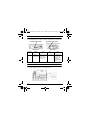
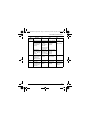
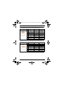
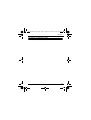
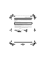
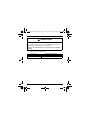
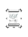
Quick Reference Step 2.book Page 1 Wednesday, October 26, 2005 8:26 PM
MAGELIS XBT GT
*35010384
01
Quick reference guide
Edition December 2005
35010384 01
Schneider Electric Industries SAS
Headquarters
89, bd Franklin Roosevelt
F - 92506 Rueil Malmaison Cedex
Owing to changes in standards and equipment,
the characteristics given in the text and images
in this document are not bound by us and are
subject to change.
http://www.schneider-electric.com
Printed in
058765F .XBTG-MT01-BTHM JM/A Copyright © 11/2003 Schneider Electric
Quick Reference Step 2.book Page 2 Wednesday, October 26, 2005 8:26 PM
Quick Reference Step 2.book Page 3 Wednesday, October 26, 2005 8:26 PM
Table of contents
Safety Instructions
Safety Precautions ...................................................................................................... 3
Standards
Presentation ................................................................................................................ 5
Overview
Specifications ...............................................................................................................7
Package Contents........................................................................................................8
Options.........................................................................................................................8
Ethernet and Serial Ports RJ45 connection .................................................................8
Part numbers and functions
XBT GT1100 ................................................................................................................9
XBT GT1130 .............................................................................................................10
XBT GT2000 Series ...................................................................................................11
RS485 Line Polarization DIP Switch .........................................................................12
CF Card DIP Switches ...............................................................................................12
Dimensions
XBT GT1000 Series ..................................................................................................15
XBT GT2000 Series ...................................................................................................15
Interfaces
XBT GT1000/2000 Series Serial Interface (RJ45) ................................................... 17
XBT GT2000 Series Serial Interface (Sub-D9-SIO)................................................. 19
Tool Port for XBT GT1000 Series ............................................................................ 20
Ethernet Interface for XBT GT1130/2110/2120/2130/2220/2330 ............................. 20
Compact Flash Memory Card Interface for XBT GT2120/2130/2220/2330 .............. 20
USB Interface for XBT GT2000 Series ..................................................................... 21
Installation and maintenance
Installation gasket ......................................................................................................23
Create a panel cut-out and insert the XBT GT into the panel from the front ............ 25
Attach the installation fastener from inside the panel ............................................... 26
Wiring ........................................................................................................................28
Replacing the Backlight .............................................................................................30
Replacing the Battery.................................................................................................32
3
Quick Reference Step 2.book Page 4 Wednesday, October 26, 2005 8:26 PM
This page was left blank intentionally.
4
Quick Reference Step 2.book Page 5 Wednesday, October 26, 2005 8:26 PM
Safety Instructions
Safety Instructions
Read these instructions carefully, and look at the equipment to become
familiar with the device before trying to install, operate, or maintain it. The
following special messages may appear throughout this documentation or
on the equipment to warn of potential hazards or to call attention to
information that clarifies or simplifies a procedure.
The addition of this symbol to a Danger or Warning safety label
indicates that an electrical hazard exists, which will result in
personal injury if the instructions are not followed.
This is the safety alert symbol. It is used to alert you to potential
personal injury hazards. Obey all safety messages that follow
this symbol to avoid possible injury or death.
DANGER
DANGER indicates a hazardous situation, which will result in death,
serious injury or equipment damage.
WARNING
WARNING indicates a potentially hazardous situation which, if not
avoided, can result in death, serious injury, or equipment damage.
CAUTION
CAUTION indicates a potentially hazardous situation, which, if not
avoided, can result in personal injury or equipment damage.
5
Quick Reference Step 2.book Page 6 Wednesday, October 26, 2005 8:26 PM
DISCLAIMER
Electrical equipment should be serviced only by qualified personnel. No
responsibility is assumed by Schneider Electric for any consequences
arising out of the use of this material. This document is not intended as an
instruction manual for untrained persons.
6
Quick Reference Step 2.book Page 7 Wednesday, October 26, 2005 8:26 PM
Standard
Presentation
The XBT GT series are UL/cUL listed and CSA certified products.
These units have been developed to the following standards:
• UL 508
Industrial Control Equipment.
• UL 1604
Electrical Equipment for Use in Class I and Class II Division 2 and III, Hazardous Locations.
• CAN/CSA-C22.2, No. 14 and No.213
Industrial Control Equipment- Miscellaneous Apparatus - For Hazardous Locations.
UL 1604 Conditions of Acceptability and Handling Cautions:
1. Power, input and output (I/O) wiring must be in accordance with Class I, Division 2
wiring methods - Article 501- 4(b) of the National Electrical Code, NFPA 70 or as
specified in section 18-152 of the Canadian Electrical Code for installations within
Canada and in accordance with the authority have jurisdiction.
2. Acceptable for use in Class I, Division 2, Groups A, B, C and D Hazardous
Locations or non- Hazardous Locations only.
WARNING
RISK OF EXPLOSION OR EQUIPMENT DAMAGE
Follow strictly the following recommendations to avoid an explosion and
physical injury:
Compatibility: Power, input and output (I/O) wiring must be in accordance
with Class I, Division 2 wiring methods - Article 501- 4(b) of the National
Electrical Code, Groups A, B, C and D Hazardous, NFPA 70 or as specified
in section 18-152 of the Canadian Electrical Code for installations within
Canada and in accordance with the authority having jurisdiction.
Confirm that the location is not subject to any risk of explosion before
connecting or disconnecting equipment, replacing or wiring modules.
Before disconnecting, replacing or wiring modules. Confirm that the
power supply has been turned OFF.
Before turning ON, sweep front panel with a wet duster.
Failure to follow this instruction can result in death, serious injury,
or equipment damage.
7
Quick Reference Step 2.book Page 8 Wednesday, October 26, 2005 8:26 PM
WARNING
LOSS OF CONTROL
• The designer of any control scheme must consider the potential failure
modes of control paths and, for certain critical control functions, provide
a means to achieve a safe state during and after a path failure. Examples
of critical control functions are emergency stop and overtravel stop.
• Separate or redundant control paths must be provided for critical
controlfunctions.
• System control paths may include communication links. Consideration
must be given to the implications of unanticipated transmission delays or
failures of the link. (*)
• Each implementation of a Magelis XBT GT must be individually and
thoroughly tested for proper operation before being placed into service.
Failure to follow this instruction can result in death, serious injury,
or equipment damage.
(*) For additional information, refer to NEMA ICS 1.1 (latest edition), “Safety
Guidelines for the Application, Installation, and Maintenance of Solid State Control”
and to NEMA ICS 7.1 (latest edition), “Safety Standards for Construction and Guide
for Selection, Installation and Operation of Adjustable-Speed Drive Systems”.
8
Quick Reference Step 2.book Page 9 Wednesday, October 26, 2005 8:26 PM
Overview
Specifications
Environment
XBT GT series
Compliance with standards
IEC 61131-2, IEC61000-6-2,CISPR11(Class A)
UL 508, CSA C22.2, No 14 & No213
Product certification
CE, UL/cUL, CSA, Class 1 Div 2 T4A* (UL & CSA)
Operating temperature
0°C … + 50°C (32°F … 122°F)
Storage temperature
-20 °C… + 60°C (-4°F … 140°F)
Humidity (without
condensation)
10% … 90%
Protection (front panel)
IP 65 - (IEC 60529) Enclosure Type 4, 4X Indoor
use with Screen Installation Fasteners only
Protection (rear panel)
IP 20 - (IEC 60529)
ESD withstand
IEC 61000 - 4 - 2
6kV, contact, 8kV air
Radiated radio frequency
electromagnetic field
IEC 61000 - 4 - 3
10 V / m
Electrical fast transient burst
IEC 61000- 4 - 4
2kV (power supply and I/O) 1kV other ports
High energy surges
IEC 61000 - 4 - 5
1KV (Differential Mode on power supply)
2KV (Common Mode on power supply)
Shocks
IEC 60068 - 2 - 27
1/2 sinusoidal pulse for 11ms, 15 g on 3 axes
Vibration
IEC 60068 - 2 - 27
3.5mm 5 Hz to 9 Hz
1 g. 9 Hz to 150 Hz
Pollution Degree
Pollution Degree 2
Power Supply
Supply voltage/ Power
consumption
24VDC/30Vrms ClassII
XBT GT1100/1130: 7W
XBT GT2110: 18W
XBT GT2120/2130/2220/2330: 26W
Voltage limits
19.2 to 28.8 VDC
9
Quick Reference Step 2.book Page 10 Wednesday, October 26, 2005 8:26 PM
Package Contents
The following items are included in the XBT GT's package. Before using the XBT GT,
please confirm that all items listed here are present:
• XBT GT Unit
• Power Plug
• Quick Reference Guide
• Screw Installation Fasteners (4)
• Installation Gasket
This unit has been carefully packed, with special attention to quality.
However, should you find anything damaged or missing, please contact your local
Schneider Electric distributor immediately.
Options
XBT GT optional items include cables, adapters, screen editor software and other items.
For more information about these optional items, please refer to individual XBT GT catalogs.
Ethernet and Serial Ports RJ45 connection
WARNING
RISK OF UNINTENDED EQUIPMENT OPERATION AND
EQUIPMENT DAMAGE
Do not connect serial cable to Ethernet port or vice versa.
Ethernet and serial ports are clearly marked.
Both the Ethernet and the serial ports use a standard RJ45 connection, making
it possible to improperly connect the communication cables to each other.
Failure to follow this instruction can result in death, serious injury,
or equipment damage.
10
Quick Reference Step 2.book Page 11 Wednesday, October 26, 2005 8:26 PM
Part numbers and functions
XBT GT1100
A: Display
B: Touch Panel
C: Power LED
D: Power Input Terminal Block
E: Serial I/F (host 8 pin RJ45)
F: Tool Port Connector
G: Function Switches (R1 to R6)
H: RS485 Line Polarization Switch
11
Quick Reference Step 2.book Page 12 Wednesday, October 26, 2005 8:26 PM
XBT GT1130
A: Display
B: Touch Panel
C: Power LED
D: Power Input
E: Serial I/F 8 pin RJ45
F: Tool port Connector
G: Function Switches (R1 to R6)
H: RS485 Line Polarization Switch
I: Ethernet Interface
12
Quick Reference Step 2.book Page 13 Wednesday, October 26, 2005 8:26 PM
Part numbers and functions
XBT GT2000 Series
A: Display
B: Touch Panel
C: Status LED
LED
XBT GT Status
Green
(lit)
Normal operation
Orange
(lit)
Backlight burnout is
detected
Orange
(blinking)
During Software startup
Red (lit)
When Power is turned
ON
Not lit
Power is OFF
D: Expansion unit Interface
E: CF Card Access Lamp (except
XBT GT2110)
E: Ethernet Interface (except
XBT GT2110/2220)(10Base-T/
100Base-TX)
G: Power Input Terminal Block
H: USB Interface (USB1.1)
I: Serial Interface COM1
J: Serial Interface COM2
K: CF Card Cover (except XBT GT2110)
L: CF Card Socket
Right
Left
CF Card Cover Open
13
Quick Reference Step 2.book Page 14 Wednesday, October 26, 2005 8:26 PM
RS485 Line Polarization DIP Switch
On XBT GT1000/2000, the RS485 Line Polarization Switch is located next to the RJ45 serial Port.
The following illustration is an example of RS485 Line Polarization Switch on XBT GT unit.
Polarization Dip Switch
Polarization Dip Switch
XBT GT2000
XBT GT1000
Polarization
Dip Switch
1
Function
ON
OFF
Note
Controls the
RS485 Serial line No polarization.
polarization of
is polarized (620
RS485 serial line. Ω pull up on D1
and 620 Ω pull
down on D0).
The polarization shall
be activated if Modbus
protocol has to be
implemented and no
other equipment
performs polarization
on the bus.
CF Card DIP Switches
On XBT GT2120/2130/2220/2330,the CF Card DIP Switches are located inside the CF Card Cover.
The following illustration display the CF Card DIP Switches.
ON
1
14
2
3
4
Quick Reference Step 2.book Page 15 Wednesday, October 26, 2005 8:26 PM
Part numbers and functions
DIP
Switches
1
Function
ON
OFF
This DIP switch setting controls the startup from a CF Card
When there is
not startup data
in the XBT GT
memory.
Startup is done
from the CF
Card(*) and the
data is also
transferred into the
XBT GT memory.
A system
message
appears
When there is
valid startup data
in the XBT GT
memory.
Startup is done
from the CF Card*
and the XBT GT
memory is updated.
Start up is done
from the
XBT GT
memory.
Note
(*): Startup
data is required
in the CF Card.
2
This dip switch
Download is
allows download
available.
application on
XBT GT products.
Download is
not available.
-
3
Reserved
-
-
-
4
This setting
controls the forced
closing of the CF
Card cover.
Forced close
enabled.
Forced close
disabled.
Used when CF
Card cover is
damaged.
15
Quick Reference Step 2.book Page 16 Wednesday, October 26, 2005 8:26 PM
This page was left blank intentionally.
16
Quick Reference Step 2.book Page 17 Wednesday, October 26, 2005 8:26 PM
Dimensions
XBT GT1000 Series
Top
Front
Right Side
XBT GT2000 Series
Top
Front
Right Side
17
Quick Reference Step 2.book Page 18 Wednesday, October 26, 2005 8:26 PM
This page left blank intentionally.
18
Quick Reference Step 2.book Page 19 Wednesday, October 26, 2005 8:26 PM
Interfaces
XBT GT1000/2000 Series Serial Interface (RJ45)
This interface is used to connect the XBT GT1000 to remote equipment, via an
RS232C or RS485 cable. The connector used is a RJ45-type connector.
Pin Arrangement
Front
Pin #
1
Signal Name
RxD
Direction
Input
2
TxD
Output
3
4
Not connected
D1
Output/Input
5
D0
Output/Input
6
7
8
RTS
Not connected
SG
Output
-
Meaning
Receive Data
(RS232C)
Send Data
(RS232C)
Transfer Data
(RS485)
Transfer Data
(RS485)
Request To Send
Signal Ground
This interface is used to connect the XBT GT2000 to remote equipment, via an
RS485cable. The connector used is a RJ45-type connector.
Pin Arrangement
Front
Pin #
1
2
3
4
Signal Name
Not connected
Not connected
Not connected
D1
Direction
Output/Input
5
D0
Output/Input
6
7
8
RTS
Not connected
SG
Output
-
Meaning
Transfer Data
(RS485)
Transfer Data
(RS485)
Request To Send
Signal Ground
19
Quick Reference Step 2.book Page 20 Wednesday, October 26, 2005 8:26 PM
WARNING
RISKS OF FIRE, UNINTENDED EQUIPMENT OPERATION,
AND EQUIPMENT DAMAGE
An excessive weight or stress on communication cables can cause a
sudden disconnection and consequently a short-circuit, fire or incorrect
unit operation. Also, a risk of power cable and communication line
damage occurs when mounting the product on installation panel or
cabinet with Power cable or Communication line already wired to unit
- Fix securely communication lines onto installation panel or cabinet to
avoid stress on connection. Use RJ45 connectors with locking system.
- Install and fasten unit on installation panel or cabinet prior to connecting
power supply and communication lines.
- Unwire power supply and communication lines prior to uninstalling unit
from panel or cabinet.
Failure to follow this instruction can result in death, serious injury,
or equipment damage.
20
Quick Reference Step 2.book Page 21 Wednesday, October 26, 2005 8:26 PM
Interfaces
XBT GT2000 Series Serial Interface (Sub-D9-SIO)
This interface is used to connect the XBT GT to remote equipment, via an RS232C or
RS422 cable. The connector used is a Sub-D9-type connector.
The following table describes the Sub-D9-type connector via an RS232C cable.
Pin Connection
Pin
Signal
Name
Direction
Meaning
1
CD
Input
Carrier Detect
2
RD(RXD)
Input
Receive Data
3
RD(RXD)
Output
Send Data
4
ER(DTR)
Output
Data Terminal Ready
5
SG
-
Signal Ground
6
DR(DSR)
Input
Data Set Ready
7
RS(RTS)
Output
Request to Send
8
CS(CTS)
Input
Send Possible
9
CI(RI)/VCC
Input
Called status display/
+5V,5% Output: 0.25A
FG
-
Frame Ground
(Common with Signal
Ground)
Shell
21
Quick Reference Step 2.book Page 22 Wednesday, October 26, 2005 8:26 PM
The following table describes the Sub-D9-type connector via an RS422 cable.
Pin Connection
Pin
Signal
Name
Direction
Meaning
1
RDA
Input
Receive Data A (+)
2
RDB
Input
Receive Data B (-)
3
SDA
Output
Send Data A (+)
4
ERA
Output
Data Terminal Ready A (+)
5
SG
-
Signal Ground
6
CSB
Input
Send Possible B (-)
7
SDB
Output
Send Data B (-)
8
CSA
Input
Send Possible A (+)
9
ERB
Output
Data Terminal Ready B (-)
FG
-
Frame Ground (Common
with Signal Ground)
Shell
Tool Port for XBT GT1000 Series
This interface accepts Serial Data Transfer Cable (XBT ZG915) or USB Data Transfer
Cable (XBT ZG925).
Ethernet Interface for XBT GT1130/2130/2330
This interface complies with the IEEE802.3 standard for Ethernet:
• (10 BASE-T) connections for XBT GT1130,
• (10BASE-T/100 BASE-TX) for XBT GT2130/2330.
This interface uses an RJ-45 type modular jack connector.
Compact Flash Memory Card Interface for XBT GT2120/2130/
2220/2330
This interface accepts a Compact Flash memory Card.
22
Quick Reference Step 2.book Page 23 Wednesday, October 26, 2005 8:26 PM
Interfaces
USB Interface for XBT GT2000 Series
This interface accepts a USB data transfer cable (XBT ZG935).
23
Quick Reference Step 2.book Page 24 Wednesday, October 26, 2005 8:26 PM
This page was left blank intentionally.
24
Quick Reference Step 2.book Page 25 Wednesday, October 26, 2005 8:26 PM
Installation and maintenance
Installation gasket
The gasket is required to absorb vibration and repel liquids.
Place the XBT GT on a smooth, level surface with the display panel facing downward.
Check that the
XBT GT's installation gasket is seated securely into the gasket’s groove, which runs
around the
perimeter of the panel’s frame.
Note:
The torque required to tighten these screws is 0.5 Nm (4.4 lb-in).
• Before installing the XBT GT into a cabinet or panel, check that the installation
gasket is securely attached to the unit.
• Make sure the gasket's seam is not inserted into any of the unit's corners, only in the
straight sections of the groove, preferably in bottom section. Inserting it into a corner
may lead to its eventually tearing.
• A gasket which has been used for a long period of time may have scratches or dirt
on it, and could have lost much of its dust and drip resistance. Make sure to change
the gasket once a year or when scratches or dirt become visible.
Rear face
Gasket
25
Quick Reference Step 2.book Page 26 Wednesday, October 26, 2005 8:26 PM
CAUTION
RISK OF EQUIPMENT DAMAGE
It is strongly recommended to use the installation gasket to maintain
IP65/IP20 protection ratings and absorb vibration.
Failure to follow this instruction can result in injury or equipment
damage.
Corresponding replacement installation gasket:
26
XBT GT Unit
Required Installation Gasket
XBT GT1000 Series
XBT ZG51
XBT GT2000 Series
XBT ZG52
Quick Reference Step 2.book Page 27 Wednesday, October 26, 2005 8:26 PM
Installation and maintenance
Create a panel cut-out and insert the XBT GT into the panel from the front
Under 4-R3 mm
Panel
[0.12 in]
A
C
B
XBT GT
XBT GT
A (mm)
B (mm)
XBT GT1100
XBT GT1130
+1
118.5
-0
+1
92.5
-0
+0.04
4.67
-0
+0.04
3.64
-0
XBT GT2110
XBT GT2120
XBT GT2130
XBT GT2220
XBT GT2330
+1
156
-0
+1
123.5
-0
+0.04
6.14
-0
+0.04
4.86
-0
A (in.)
B (in.)
C (mm)
C (in.)
1.6 to 5.0
0.06 to 0.2
1.6 to 5.0
0.06 to 0.2
27
Quick Reference Step 2.book Page 28 Wednesday, October 26, 2005 8:26 PM
Attach the installation fastener from inside the panel
Spring Clip Installation:
There is only one kind of spring clip used, but it is installed in two different ways.
The following figure displays how to adjust, insert, and unlock the spring clip:
Position 1
Position 2
To Lock
To Unlock
Note:
Adjust the Spring clip according to panel’s thickness:
• 1.6 mm (0.06 in.) ≤ panel thickness ≤ 4 mm (0.16 in.) (position 1).
• 4 mm (0.16 in.) ≤ panel thickness ≤ 6 mm (0.24 in.) (position 2)
28
Quick Reference Step 2.book Page 29 Wednesday, October 26, 2005 8:26 PM
Installation and maintenance
Screw Installation Fastener
The following figure shows the Screw Installation Fastener insertion slot locations.
Insert each fastener's hook into the slot and tighten it with a screwdriver. The
necessary torque is 0.5 N.m (4.4 lb-in.).
Panel
Screw Installation Fastener
XBT GT
CAUTION
RISK OF EQUIPMENT DAMAGE
Do not exert more than 0.5 N.m (4.4 in-lb) of torque when tightening the
fastener screws.Tightening the screws with excessive force can damage
the XBT GT's plastic case.
Failure to follow this instruction can result in injury or equipment
damage.
Note:
• Depending on the installation panel's thickness, etc., the number of
installation fasteners used may need to be increased to provide the
desired level of moisture resistance.
• The necessary torque is 0.5 N.m (4.4 lb-in)
29
Quick Reference Step 2.book Page 30 Wednesday, October 26, 2005 8:26 PM
Wiring
Power Cord Specifications
Follow these steps for a successful installation:
1. Make sure the wire size is between 0.2 and 2.5 mm² (24 - 12 AWG) for the power cords.
2. Twist the wire ends before attaching the terminals.
3. When the Frame Ground terminal is connected, make sure the wire is grounded.
Not grounding the XBT GT unit will result in excess noise.
WARNING
RISK OF ELECTRIC SHOCK AND EQUIPMENT DAMAGE
Follow these precautions to avoid risks of electric shocks:
• Be sure the power cord is unplugged from the power outlet when
connecting the power terminals to the XBT GT unit.
• The XBT GT1000 and the XBT GT2000 are using only 24V DC power.
Using any other level of power can damage both the power supply and
the XBT GT unit.
• Since the XBT GT is not equipped with the power switch, be sure to
connect a breaker type power switch to the XBT GT’s power cord.
• Be sure to ground the XBT GT's FG terminal. Failure to do so can lead
to an electrical shock or XBT GT malfunction.
Failure to follow this instruction can result in death, serious injury,
or equipment damage.
30
Quick Reference Step 2.book Page 31 Wednesday, October 26, 2005 8:26 PM
Installation and maintenance
Grounding the wire and conductor length
Grounding is required to ensure EMC level immunity. The Conductor Type is simple
or stranded wire.
The following illustration displays the conductor length:
FG
Insertion
Direction
Terminal block
wire set block
Power Plug
FG
Connecting the XBT GT Power Cord
When connecting the power cord, follow these steps:
1. Remove all power connected to XBT GT.
2. Remove the clear plastic cover on end wire (7mm or 0.28inch).
3. Loosen the screws from the middle three terminals.
4. Ensure the proper wire is installed into the correct position on the Power Plug.
5. Confirm the correct connection points.
6. Torque the mounting screws to the required torque.
Note:
The torque required to tighten these screws is 0.5 Nm (4.4 lb-in).
31
Quick Reference Step 2.book Page 32 Wednesday, October 26, 2005 8:26 PM
Replacing the Backlight
Introduction
The XBT GT unit's backlight is not user replaceable. Contact your Schneider Electric
representative for technical support.
DANGER
RISKS OF UNINTENDED EQUIPMENT OPERATION AND
ELECTRIC SHOCK.
If the operator fails to notice that the backlight is burned out and touches
the panel, unintended equipment operation can occur.
If the XBT GT unit’s “Backlight Control” has burned out and the unit is not
set to Standby Mode, the touch panel remains active.
Do not create XBT GT touch panel switches for system functions which
may cause injury and/or equipment damage if activated accidentally.
Do not disassemble the XBT GT or attempt to repair/replace the
backlight. Unshielded high voltages are present within the backlight
even when the power is off.
Failure to follow this instruction will result in death, serious injury,
or equipment damage.
Determining if the backlight has burned out
If your XBT GT unit’s backlight suddenly turns OFF, use the following steps to
determine if the backlight is actually burned out:
• If the XBT GT unit’s “Backlight Control” is not set and the screen has gone blank,
your backlight is burned out.
• If the XBT GT unit’s “Backlight Control” is set to Standby Mode and the screen has
gone blank, and touching the screen or performing another input operation does
not cause the display to reappear, your backlight is burned out.
32
Quick Reference Step 2.book Page 33 Wednesday, October 26, 2005 8:26 PM
Installation and maintenance
Corresponding Replacement Backlights:
XBT GT Unit
Required Backlight Model
XBT GT1000 Series
Cannot be replaced by User(1)
XBT GT2000 Series
Cannot be replaced by User(1)
(1): The unit must be returned to an authorized Schneider Electric repair center for
backlight replacement
Note:
Backlight models are not interchangeable.
33
Quick Reference Step 2.book Page 34 Wednesday, October 26, 2005 8:26 PM
Replacing the Battery
WARNING
RISK OF BATTERY EXPLOSION
Do not attempt to replace the XBT GT battery.
If the battery is incorrectly replaced, the battery may explode the next
time you use it.
To replace the XBT GT battery, contact the Schneider Electric support
center for the address of your local Schneider Electric representative.
Failure to follow this instruction can result in death, serious injury,
or equipment damage.
34