1
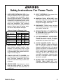
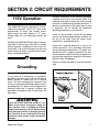
MINI SHAPER MODEL G8693
INSTRUCTION MANUAL
COPYRIGHT © 2000 BY GRIZZLY INDUSTRIAL, INC.
1821 VALENCIA ST., BELLINGHAM, WA 98227
WARNING: NO PORTION OF THIS MANUAL MAY BE REPRODUCED IN ANY SHAPE
OR FORM WITHOUT THE WRITTEN APPROVAL OF GRIZZLY INDUSTRIAL, INC.
JUNE 2000 PRINTED IN CHINA.
-2-
G8693 Mini Shaper
Table Of Contents
PAGE
1.
2.
3.
4.
5.
6.
7.
8.
SAFETY
SAFETY INSTRUCTIONS FOR POWER TOOLS ................................................3-4
ADDITIONAL SAFETY INSTRUCTIONS FOR SHAPERS ......................................5
CIRCUIT REQUIREMENTS
110V OPERATION ....................................................................................................6
GROUNDING ............................................................................................................6
GENERAL INFORMATION
COMMENTARY ........................................................................................................7
UNPACKING..............................................................................................................7
PARTS INVENTORY................................................................................................8
CLEAN UP ................................................................................................................9
ASSEMBLY
STUB SHAFT ..........................................................................................................10
FENCE ....................................................................................................................11
RING GUARD ..........................................................................................................11
SITE CONSIDERATIONS ......................................................................................12
OPERATIONS
OVERVIEW..............................................................................................................13
ON/OFF SWITCH ....................................................................................................14
FENCE ....................................................................................................................14
DEPTH OF CUT ......................................................................................................14
TABLE INSERT ......................................................................................................15
SPINDLE HEIGHT ..................................................................................................15
RING GUARD ..........................................................................................................16
KEYED WASHERS ................................................................................................16
INSTALLING A CUTTER ........................................................................................17
USING ROUTER BITS ............................................................................................17
WORKPIECE PREP ................................................................................................18
WOOD GRAIN ........................................................................................................18
STRAIGHT EDGE SHAPING ..................................................................................19
ACROSS THE GRAIN ............................................................................................19
LARGE WORKPIECE..............................................................................................20
CURVED WORKPIECE ..........................................................................................20
DUST COLLECTION ..............................................................................................21
MAINTENANCE ............................................................................................................22
BELT REPLACEMENT ............................................................................................22
CLOSURE ....................................................................................................................23
DATA SHEET ..........................................................................................................24
PARTS BREAKDOWN ............................................................................................25
PARTS LIST ............................................................................................................26
WARRANTY ..................................................................................................................27
G8693 Mini Shaper
-3-
SECTION 1: SAFETY
For Your Own Safety Read Instruction Manual
Before Operating This Equipment
The purpose of safety symbols is to attract your attention to possible hazardous conditions.
This manual uses a series of symbols and signal words which are intended to convey the level
of importance of the safety messages. The progression of symbols is described below.
Remember that safety messages by themselves do not eliminate danger and are not a substitute for proper accident prevention measures.
Indicates an imminently hazardous situation which, if not
avoided, WILL result in death or serious injury.
Indicates a potentially hazardous situation which, if not avoided, COULD result in death or serious injury.
Indicates a potentially hazardous situation which, if not avoided, MAY result in minor or moderate injury. It may also be
used to alert against unsafe practices.
NOTICE
This symbol is used to alert the user to useful information
about proper operation of the equipment.
Safety Instructions For Power Tools
1.
KEEP GUARDS IN PLACE and in working
order.
2.
REMOVE ADJUSTING KEYS AND
WRENCHES. Form habit of checking to
see that keys and adjusting wrenches are
removed from tool before turning on.
3.
KEEP WORK AREA CLEAN. Cluttered
areas and benches invite accidents.
4.
DON’T USE IN DANGEROUS ENVIRONMENT. Don’t use power tools in damp or
wet locations, or where any flammable or
noxious fumes may exist. Keep work area
well lighted.
-4-
5.
KEEP CHILDREN AND VISITORS
AWAY. All children and visitors should be
kept a safe distance from work area.
6.
MAKE WORK SHOP CHILD PROOF with
padlocks, master switches, or by removing
starter keys.
7.
DON’T FORCE TOOL. It will do the job
better and safer at the rate for which it was
designed.
8.
USE RIGHT TOOL. Don’t force tool or
attachment to do a job for which it was not
designed.
G8693 Mini Shaper
Safety Instructions For Power Tools
9.
USE PROPER EXTENSION CORD. Make
sure your extension cord is in good condition. Conductor size should be in accordance with the chart below. The amperage
rating should be listed on the motor or tool
nameplate. An undersized cord will cause
a drop in line voltage resulting in loss of
power and overheating. Your extension
cord must also contain a ground wire and
plug pin. Always repair or replace extension cords if they become damaged.
Minimum Gauge for Extension Cords
AMP RATING
0-6
7-10
11-12
13-16
17-20
21-30
LENGTH
25ft 50ft 100ft
18
16
16
18
16
14
16
16
14
14
12
12
12
12
10
10
10
No
10. WEAR PROPER APPAREL. Do not wear
loose clothing, gloves, neckties, rings,
bracelets, or other jewelry which may get
caught in moving parts. Non-slip footwear
is recommended. Wear protective hair covering to contain long hair.
11. ALWAYS USE SAFETY GLASSES. Also
use face or dust mask if cutting operation is
dusty. Everyday eyeglasses only have
impact resistant lenses, they are NOT safety glasses.
13. DON’T OVERREACH. Keep proper footing and balance at all times.
14. MAINTAIN TOOLS WITH CARE. Keep
tools sharp and clean for best and safest
performance. Follow instructions for lubricating and changing accessories.
15. DISCONNECT TOOLS before servicing
and changing accessories, such as blades,
bits, cutters, and the like.
16. REDUCE THE RISK OF UNINTENTIONAL STARTING. Make sure switch is in off
position before plugging in.
17. USE RECOMMENDED ACCESSORIES.
Consult the owner’s manual for recommended accessories. The use of improper
accessories may cause risk of injury.
18. CHECK DAMAGED PARTS. Before further use of the tool, a guard or other part
that is damaged should be carefully
checked to determine that it will operate
properly and perform its intended function.
Check for alignment of moving parts, binding of moving parts, breakage of parts,
mounting, and any other conditions that
may affect its operation. A guard or other
part that is damaged should be properly
repaired or replaced.
19. NEVER LEAVE TOOL RUNNING UNATTENDED. TURN POWER OFF. Don’t
leave tool until it comes to a complete stop.
12. SECURE WORK. Use clamps or a vise to
hold work when practical. It’s safer than
using your hand and frees both hands to
operate tool.
G8693 Mini Shaper
-5-
Safety Instructions For Shapers
1. Wear eye protection.
6. Keep fingers away from revolving cutter use fixture when necessary.
2. Wear ear protection.
3. Be sure keyed washer is directly under
spindle nut and that spindle nut is tight.
4. Feed workpiece against rotation of cutter.
7. Use overhead guard when adjustable fence
is not in place.
8. Mini Shaper should be fastened securely to
a firm supporting surface.
5. Do not use awkward hand positions.
Like all power tools, there is danger associated with the Model G8693 Mini Shaper.
Use the tool with respect and caution to
lessen the possibility of mechanical damage or operator injury. If normal safety precautions are overlooked or ignored, serious personal injury may occur.
No list of safety guidelines can be complete. Every shop environment is different.
Always consider safety first, as it applies to
your individual working conditions. Use
this and other machinery with caution and
respect. Failure to do so could result in
serious personal injury, damage to equipment or poor work results.
Operation of this equipment has the potential to propel debris into the air which can
cause eye injury. Always wear safety glasses or goggles when operating equipment.
Everyday glasses or reading glasses only
have impact resistant lenses, they are not
safety glasses. Be certain the safety glasses you wear meet the appropriate standards of the American National Standards
Institute (ANSI).
-6-
G8693 Mini Shaper
SECTION 2: CIRCUIT REQUIREMENTS
110V Operation
Your G8693 Mini Shaper is prewired for 110 volt,
single phase operation. The 3⁄4'' H.P. motor draws
approximately 2.2 amps. We strongly recommend fusing your Mini Shaper at 15 amps.
Fusing higher will not adequately protect the
motor.
Although the G8693 Mini Shaper does not draw a
large load, if you’re using a circuit that is already
close to capacity, it might blow a fuse or trip a circuit breaker. If an unusual load does not exist and
power failure still occurs, have the circuit inspected by a qualified electrician.
Improper connections of the electrical-grounding
conductor can result in risk of electric shock. The
conductor with green or green and yellow striped
insulation is the electrical-grounding conductor. If
repair or replacement of the electric cord or plug
is necessary, do not connect the equipment
grounding conductor to a live terminal.
Under no circumstances should the grounding
pin from any three-pronged plug be removed. If it
will not fit the outlet, have the proper outlet
installed by a qualified electrician.
Check with a qualified electrician or one of our
service personnel if the grounding instructions
are not completely understood, or if in doubt as to
whether the tool is properly grounded. Use only
3-wire extension cords that have 3-prong grounding type plugs and 3-hole receptacles that accept
the tool’s plug. See FIgure 1.
Repair or replace damaged or worn cord immediately.
Grounding
In the event of a malfunction or breakdown,
grounding provides a path of least resistance for
electric current to reduce the risk of electric
shock. This tool is equipped with an electric cord
having an equipment-grounding conductor and a
grounding plug. The plug must be plugged into a
matching outlet that is properly installed and
grounded in accordance with all local codes and
ordinances.
If you are unsure about the quality or condition of the circuit you plan on using for
this machine, have a qualified electrician
inspect and repair the circuit. Always make
sure that your machine is properly grounded. Failure to do so could result in serious
electrical shock hazard and/or mechanical
damage.
G8693 Mini Shaper
Figure 1.
-7-
SECTION 3: GENERAL INFORMATION
Commentary
We are proud to offer the G8693 Mini Shaper.
The Model G8693 is part of a growing Grizzly
family of fine woodworking machinery. When
used according to the guidelines set forth in this
manual, you can expect years of trouble-free,
enjoyable operation and proof of Grizzly’s commitment to customer satisfaction.
We are also pleased to provide this manual with
the Model G8693. It was written to guide you
through assembly, review safety considerations,
and cover general operating procedures. It represents our effort to produce the best documentation possible. If you have any comments regarding this manual, please write to us at the address
below:
Grizzly Industrial, Inc.
C/O Technical Documentation
P.O. Box 2069
Bellingham, WA 98227-2069
Most importantly, we stand behind our machines.
If you have any service questions or parts
requests, please call or write us at the following
location:
-8-
Grizzly Industrial, Inc.
1203 Lycoming Mall Circle
Muncy, PA 17756
Phone: (570) 546-9663
Fax: (800) 438-5901
E-Mail: [email protected]
Web Site:www.grizzly.com
The specifications, drawings, and photographs
illustrated in this manual represent the Model
G8693 as supplied when the manual was prepared. However, owing to Grizzly’s policy of continuous improvement, changes may be made at
any time with no obligation on the part of Grizzly.
Whenever possible, though, we send manual
updates to all owners of a particular tool or
machine. Should you receive one, we urge you to
insert the new information with the old and keep
it for reference.
To operate this, or any power tool, safely and
efficiently, it is essential to become as familiar
with its characteristics as possible. The time
you invest before you begin to use your Model
G8693 will be time well spent. DO NOT operate this machine until you are completely familiar with the contents of this manual. Make sure
you read and understand all of the safety procedures. If you do not understand something,
DO NOT operate the machine.
G8693 Mini Shaper
Unpacking
Parts Inventory
Model G8693 Mini Shaper is Shipped complete in
one carton. If you discover the machine is damaged after you’ve signed for delivery, and the
truck and driver are gone, you will need to file a
freight claim with the carrier. Save the containers
and all packing materials for possible inspection
by the carrier or its agent. Without the packing
materials, filing a freight claim can be difficult. If
you need assistance determining whether you
need to file a freight claim, or with the procedure
to file one, please contact our Customer Service.
After all parts have been removed from the box,
you should have:
When you are completely satisfied with the condition of your shipment, you should inventory its
parts.
1
3
1
1
2
1
1
1
1
1
1
2
1
Mini Shaper Unit
Knobs
Fence Assembly
Miter Gauge
Spindle Wretches
Router Bit Collet
Guide Pin
Dust Port
Hose Adapter
Stub Shaft
Plastic Guard
Extra Motor Brushes
Extra Motor Belt
In the event that any parts are missing, we will be
happy to replace them. Contact our Customer
Service number for assistance. If any non-proprietary parts such as nuts, bolts or washers are
missing, we will be happy to replace these too,
but for the sake of expediency, these items can
be obtained at your local hardware store.
G8693 Mini Shaper
-9-
Clean Up
The unpainted surfaces are coated with a waxy oil to protect them from corrosion during shipment. Remove
this protective coating with a solvent cleaner or citrus-based Degreaser such as Grizzly’s G7895
Degreaser. Avoid chlorine-based solvents as they may damage painted surfaces should they come in contact. Always follow the usage instructions on the product you choose for clean up.
Many of the solvents commonly used to
clean machinery can be highly flammable,
and toxic when inhaled or ingested. Always
work in well-ventilated areas far from
potential ignition sources when dealing
with solvents. Use care when disposing of
waste rags and towels to be sure they do
not create fire or environmental hazards.
Keep children and animals safely away
when cleaning and assembling this
machine.
Do not use gasoline or other petroleumbased solvents to remove this protective
coating. These products generally have low
flash points which makes them extremely
flammable. A risk of explosion and burning
exists if these products are used. Serious
personal injury may occur.
All die-cut metal parts have a sharp edge
(called “flashing”) on them after they are
formed. This is generally removed at the
factory. Sometimes a bit of flashing might
escape inspection, and the sharp edge may
cause cuts or lacerations when handled.
Please examine the edges of all die-cut
metal parts and file or sand the edge to
remove the flashing before handling.
-10-
G8693 Mini Shaper
SECTION 4: ASSEMBLY
Spindle Shaft
For Your Own Safety, Never Connect To Power
Source Until All Assembly Steps Are Complete,
And You Have Read And Understand The Safety
And Operational Instructions.
3. Lock the assembly in place by tightening the
Shaper Nut with the wrenches provided. See
Figure 3.
NOTE: If you would like to use Router bits
instead of Shaper cutters, see section on
“Using Router Bits” for instructions.
Typically, the Spindle Shaft is already installed
from the factory. To remove the Spindle, reverse
the following steps.
1. Place the Shaper Nut (REF 36) onto the
Spindle Shaft (REF 35) and insert the Shaft
into the Spindle Bore. See Figure 2.
2. Shaper Nut must be screwed onto the threaded portion of the Spindle Bore.
Spindle Shaft
Figure 3. Tightening Spindle.
Shaper Nut
Spindle Bore
Figure 2. Set Spindle into hole.
G8693 Mini Shaper
-11-
Fence
Ring Guard
1. Find three Knobs (REF 14) and three rubber
faced Washers (REF 13) from the parts bag.
1. Attach the Ring Guard (REF 19) to the Post
(REF 21) using one #10-24 x 1⁄2'' Pan Head
Screw (REF 18).
2. Mount the Fence Body (REF 12) on the Table
(REF 10) using two knobs and washers.
Screw the knobs through the slots of the fence
body and into the threaded holes near the rear
of the table. See Figure 4.
2. Slide the assembly into the unthreaded hole
near the rear of the table.
3. Use knob (REF 14) from the parts bag to set
the height of the Ring Guard. See Figure 5.
3. Place the Fence Segment (REF 15) in the V
groove on the Fence Body and screw the third
knob and washer into the threaded hole in the
Fence Body.
4. If you plan to use a dust collection system with
your mini Shaper, attach the Dust Port to the
back of the Fence using the four M5-0.8 x
10mm screws supplied.
Figure 5. Guard installed.
Figure 4. Mounting Fence Body On Table.
-12-
G8693 Mini Shaper
Site Consideration
If the Mini Shaper is to be used in a permanent
location, it should be fastened securely to a firm
supporting surface such as a workbench. Holes
should be drilled through supporting surface of
the workbench as illustrated. Each foot of the Mini
Shaper should be bolted securely using 1⁄4'' bolts,
hex nuts and lock washers. Bolts should be of
sufficient length to accommodate foot of Mini
Shaper, washer, hex nut and thickness of supporting surface. Tighten all four bolts securely. If
the Mini Shaper is to be used in a portable application, it is recommended that it be fastened to a
mounting board. The board should be of sufficient
size to avoid tipping of the Mini Shaper while in
use. Any good grade of plywood or chipboard
with a 3⁄4'' minimum thickness is recommended.
Mount Mini Shaper to board using hole pattern as
shown. Before each use, clamp board securely to
workbench or supporting surface.
Supporting surface where Mini Shaper is mounted should be examined carefully after mounting
to insure that no movement during use can result.
If any “tipping” or “walking” is noted, secure workbench or supporting surface before operating.
Bench Load: Your G8693 Mini Shaper represents a small weight load in a small footprint.
Most commercial or home shop benches should
be sufficient to carry the weight of the G8693. If
you question the strength of your workbench, you
can opt to reinforce it, or consider securing the
Mini Shaper on a freestanding bench like
Grizzly’s Shop Fox® tool table.
Working Clearances: Working clearances can
be thought of as the distances between machines
and obstacles that allow safe operation of every
machine without limitation. Consider existing and
anticipated machine needs, size of material to be
processed through each machine, and space for
auxiliary stands and/or work tables. Also consider the relative position of each machine to one
another for efficient material handling. Be sure to
allow yourself sufficient room to safely run your
machines in any foreseeable operation.
Lighting and Outlets: Lighting should be bright
enough to eliminate shadow and prevent eye
strain. Electrical circuits should be dedicated or
large enough to handle combined motor amp
loads. Outlets should be located near each
machine so power or extension cords are not
obstructing high-traffic areas. Be sure to observe
local electrical codes for proper installation of
new lighting, outlets, or circuits.
Make your shop “child safe”. Ensure that
your workplace is inaccessible to youngsters by closing and locking all entrances
when you are away. Never allow visitors in
your shop when assembling, adjusting or
operating equipment.
Figure 6. Hole Pattern
G8693 Mini Shaper
-13-
SECTION 4: OPERATIONS
Fence Assembly
Infeed Fence
Ring Guard Lock Knob
Spindle Adjustment Knob
Figure 7. Location Of Primary Components.
Operating this equipment has the potential
for hearing damage to occur, especially if
operated for a long period of time. Always
wear hearing protection when operating
equipment. Cotton balls or tissue paper in
the ear canal does not provide adequate
noise reduction. Use an ANSI (American
National Standards Institute) approved ear
muff or ear plug when using this equipment.
-14-
Operating this equipment has the potential
to propel debris into the air which can
cause eye injury. Always wear safety glasses or goggles when operating equipment.
Everyday glasses or reading glasses only
have impact resistant lenses, they are not
safety glasses. Be certain the safety glasses you wear meet the appropriate standards of the American National Standards
Institute (ANSI).
G8693 Mini Shaper
On-Off Switch
Fence
The “On-Off” switch is located on the front of your
Mini Shaper and has the operating positions
clearly marked. Push the switch up to turn your
tool “On” and down to turn it “off” The switch has
a switch key which, when removed, allows the
switch to be locked in the “off” position. To activate the locking feature, push switch to “off” position and pull the switch key. See Figure 8.
The entire Fence Assembly (REF 64) can be
moved by loosening the two outer knobs and sliding the Fence in the slots until the desired position is reached. Lock the Fence in place by tightening the knobs. The fence does not need to be
straight with the table unless a miter gauge is
being used to align the workpiece.
The Fence Segment (REF 15) can be adjusted
independent of the Fence Body (REF 12).
Depth Of Cut
Figure 8. Switch Assembly With locking key.
Depth of cut can be changed three different ways;
moving the fence, adjusting the spindle height
and by using collars.
Be sure switch is locked in “off position after
removing switch key. Before removing switch
key, unplug your Mini Shaper. Failure to unplug
Mini Shaper could result in accidental starting
causing serious injury.
To turn Mini Shaper “On” after it has been locked
in the “off” position, the switch key must be
replaced in the switch. Be sure switch is in the
“off” position before plugging Mini Shaper in.
G8693 Mini Shaper
-15-
Table Insert
Spindle Height
The Table Insert (REF 16) should be used at all
times to provide support for the workpiece.
The Spindle has a maximum vertical adjustment
of 3⁄4''. The large knob on the rear of the Shaper/
Router is used to set the height. Loosen the knob
by turning it counterclockwise. The Spindle
assembly can now be raised or lowered by moving the knob right or left in the inclined slot. When
the desired height is obtained, turn the knob
clockwise to lock it in place. See Figure 11.
When the cutter or bit is completely above the
table surface, the Table Insert should be used with
the smaller (13⁄8'') hole facing up. See Figure 9.
Spindle cutters can be raised by using the collar
(REF 59) provided.
Insert Removed
Figure 9. Guard Removed For Clarity.
When the cutter or router bit is below the surface
of the table, the Table Insert should be used with
the 2-5⁄8'' opening facing up. See Figure 10.
Always make sure the cutter will not hit the Insert
before turning on the Mini Shaper.
Figure 11. Spindle height locking knobs.
Insert Installed
Figure 10. Guard Removed For Clarity.
-16-
G8693 Mini Shaper
Ring Guard
Keyed Washers
The Ring Guard (REF 19) is an important safety
feature and should always be used when shaping. Before the Mini Shaper is turned on, the ring
guard should be positioned approximately 1⁄4''
above the workpiece and locked in place.
The keyed Washer must be directly under the
JAM NUT; otherwise, the nut may loosen and
serious injury may result. Always lock the spindle
knob after adjusting it. See Figure 13.
When making adjustments or setting the cutter,
the Ring Guard can be loosened and rotated out
of the way.
Jam Nut
Keyed Washer
Figure 13.
Figure 12.
G8693 Mini Shaper
-17-
Installing A Cutter
Using Router Bits
Before making any adjustments or conversions to
the Mini Shaper, make sure the switch is in the
'OFF' position and the power cord is
UNPLUGGED.
The G8693 Mini Shaper is equipped with a
removable 1⁄2'' Stub Shaft and a 1⁄4'' router bit collet. See Figure 16.
Be sure the Table Insert (REF 16) is installed and
not in contact with the cutter prior to operation.
Before making any adjustments or conversions to
the Mini Shaper, make sure the switch is in the
'OFF' position and the power cord is
UNPLUGGED.
The cutter rotates in a counterclockwise direction.
Be careful to mount the cutter with the cutting
face toward the infeed as it rotates. See Figure
15. If mounted upside-down, the cutter can kick
the wood back and injure the operator. Install the
keyed washer (REF 34) directly under the jam nut
(REF 33) and hold the spindle shaft (REF 39) with
wrench provided. Be sure to tighten the nut
before turning on the Mini Shaper. For best leverage, hold wrench against the table support boss
or squeeze them together using one hand.
Remove any dirt or wood chips found in the top of
the spindle. Place the Collet (REF 62) into the
Spindle (REF 39) and thread the Router Nut
(REF 63) down over the Collet, leaving it loose
enough to insert the shank of a Router Bit. Insert
a Router Bit into the Collet at least 5⁄8'' and tighten the Router Nut only until you cannot turn the
bit by hand while holding the Spindle (REF 39)
with the 5⁄8'' Wrench (REF 57).
Some height adjustment can be made by raising
or lowering the Router Bit in the Collet. For further
height adjustment, refer to instructions on
Spindle Height on page 15.
To change Router Bits or to remove the Collet
assembly, hold the Spindle in place with the 5⁄8''
Wrench while loosening the Router nut with the
1'' Wrench. The Router bit should ‘pop’ loose
from the Collet and pull out. Be careful that wood
chips and dirt do not get inside the Spindle as
they may damage the tapered faces.
Be sure to follow the instructions in the ASSEMBLY chapter when returning the tool to the
Shaper configuration using the Stub Shaft.
Figure 15.
-18-
G8693 Mini Shaper
Workpiece Prep
Do not use the Mini Shaper to reduce workpiece
size. The workpiece should be cut as close to
final size before shaping. For best results, run all
sides to be shaped through a jointer.
Whenever a cutter is required to make a heavy
cut, the spindle speed (RPM) may be reduced.
This results in a rough or splintered cut.
Excessive depth-of-cut can also cause kickback!
Always make a test cut on a piece of scrap before
using the finished workpiece.
Figure 16.
Wood Grain
The Shaper cutter runs at high RPM, so with most
woods it makes little difference if the cut is with or
against the grain. However, with some very open
grained woods such as redwood or fir, cutting
against the grain may result in a rough, splintered
surface. In this situation and when a heavy cut
must be made, it is advisable to make a series of
light cuts. Make the final cut by removing 1⁄16'' or
less material.
G8693 Mini Shaper
-19-
Straight Edge Shaping
Across The Grain
After installing the cutter but before plugging in,
(be sure to check for proper rotation) position the
fence faces parallel to each other and lock them
in place. Rotate the cutter until one of the cutting
face’s is 90 degrees from the fence faces. Place
the workpiece against the infeed fence and slide
it against the face of the cutter to get an idea of
the cut profile. Now adjust the Spindle height and
the Fence location to give the approximate cut
profile. A drawn outline of the desired cut profile
on the end of the workpiece will help in making
adjustments. Try out the setting on a piece of
scrap and then make final adjustments.
Always install the keyed washer directly under
the jam nut; otherwise, the nut may loosen and
serious injury may result.
A cross-grain cut will result in splintering of the
back edge. Two common methods to reduce this
problem are:
1. Cut the workpiece about 1⁄4'' oversize and trim
after shaping.
2. Clamp a piece of scrap to the trailing edge of
the workpiece while shaping. See Figure 17.
If the entire face of the workpiece is to be shaped,
make a test cut with scrap.
When about 2'' of the test piece is adjacent to-the
outfeed side of the Fence, stop the Shaper and
unplug it! Clamp the test piece to the table so it
will not move from that position. Loosen all three
knobs holding the Fence and Fence Segment.
Slide both Fence faces until they support the
workpiece completely. Lock all of the knobs
securely before resuming the test cut.
Figure 17.
-20-
G8693 Mini Shaper
Large Workpiece
When shaping long, wide or cumbersome workpieces, the table may be too small to provide full
support. An extension for the table can be added
to the sides and front. Use only smooth, flat wood
and be sure the extension is on the same level as
the Mini Shaper table.
The Fence faces are drilled to allow the addition
of fence extensions or wooden faces to provide
more support.
Many good books on woodworking provide
detailed instructions on shaper operation, patterns, fixtures and jigs.
Keep hands in the clear. Never jeopardize your
hands; keep them at least six inches from the cutter at all times. If workpiece is small, use a holding jig of some type to guide it past the cutter.
Ring Guard (REF 19) should be used and properly adjusted when fence is removed.
Figure 18.
Two methods are used for shaping curved or
irregular edges:
1. Collar-This method can be used when at least
1
⁄8'' of edge will remain uncut. Workpiece is cut
and sanded to exact shape desired. Rest
workpiece against radius pin and feed straight
into cutter until finished edge is against collar.
Keep edge being shaped at 90 degrees to collar. Hold part firmly against collar and slowly
feed around shape until complete.
2. Pattern-A pattern or template can be cut from
1
⁄4'' hardboard or scrap wood. This method is
the best way to make several pieces of the
same shape. Allow for diameter of collar, contour shape and depth of cut when cutting pattern.
Curved Workpiece
When the edge to be shaped is not straight,
remove Fence assembly and replace it with
Radius Pin (REF 11) and a collar. Collar can be
solid or ball bearing and is mounted above or
below cutter on stub shaft to set the depth of cut
(see accessories section). See Figure 18.
G8693 Mini Shaper
Workpiece should be cut to a shape close to pattern. Fasten the pattern to workpiece using
clamps, screws, brads or rubber cement. Feed
workpiece into cutter until collar contacts pattern.
Slowly feed workpiece around pattern holding
pattern tight against collar. Remember to do any
cross grain cut first to prevent splintering on finished workpiece.
-21-
Dust Collection
Your Mini Shaper has a rear chip discharge which
fits any standard dust collection with a 21⁄2'' hose.
A 21⁄2'' to 11⁄4'' hose adapter is supplied with the
Mini Shaper. Attaching a dust collection system
will keep your work area cleaner.
If Chip Discharge clogs with chips, turn switch
OFF and UNPLUG unit to avoid accidental starting. Dislodge chips and debris with a pencil or
wood dowel, minimum 6 inches in length.
Do not use finger since stationary blades are
sharp.
Figure 19.
When resuming operation, feed at a slower rate
to avoid re-clogging. Use of a Wet-Dry Vac will
virtually eliminate the chance of clogging.
Never leave hose connected to the machine during operation if a vac is not turned on. The hose
and machine will clog with chips.
-22-
G8693 Mini Shaper
SECTION 5: MAINTENANCE
Keep your Mini Shaper clean and adjusted properly for maximum performance and machine
longevity. Do not allow pitch to accumulate on the
table, fences or cutters. Clean frequently with
Gum and Pitch Remover.
2. Turn Mini Shaper upside down on a firm work
surface. Be careful to remove or protect the
Stub Shaft from damage.
3. Remove Belt Guard (REF 47) by loosening
the mount screw (REF 49).
The table and other non-painted surfaces on the
Model G8693 should be protected against rust
and pitting. Wiping the Shaper clean after every
use ensures that moisture from wood dust isn’t
allowed to trap moisture against bare metal surfaces.
4. Remove old Timing Belt (REF 46) by turning
belt and applying outward pressure.
Some woodworkers recommend using automotive paste wax on exposed steel and cast iron
surfaces. The wax provides a layer of protection,
as well as reducing friction between lumber and
the table, making cuts faster and smoother. Avoid
waxes that contain silicone or other synthetic
ingredients. These materials can find their way
into lumber that’s being worked, and can make
staining and finishing difficult. If you use paste
wax, make sure that it’s 100% Carnauba wax.
6. Should the belt tension need adjustment,
loosen four hex head bolts (REF 61) on Motor
Mount (REF 54). Slide Motor Mount in or out
until sides of timing belt are straight between
pulleys. NOTE: Do not over-tension this belt,
it only needs to be straight. Excessive tension
may shorten the life of the motor bearings.
Tighten bolts and make sure the belt runs
straight and true.
5. Install new belt by starting it on pulleys and
maintain inward pressure until full width of belt
is on both pulleys.
7. Replace the belt guard before operating.
For your safety, turn the Mini Shaper off,
remove the switch key and disconnect the
machine from power source before
attempting any repairs or maintenance on
the shaper. Failure to observe this will
result in serious personal injury.
Belt Replacement
Replacement belts are available from Grizzly
Parts Department.
Figure 20.
1. Turn the Mini Shaper off, remove the switch
key and unplug!
Failure to unplug your Mini Shaper could
result in accidental starting and serious injury
and that would be bad.
G8693 Mini Shaper
-23-
SECTION 6: CLOSURE
The following pages contain general machine
data, parts diagrams/lists, troubleshooting guide
and Warranty/Return information for your Model
G8693 Mini Shaper.
If you need parts or help in assembling your
machine, or if you need operational information,
we encourage you to call our Service
Department. Our trained service technicians will
be glad to help you.
If you have comments dealing specifically with
this manual, please write to our Bellingham,
Washington location using the address in Section
3:GENERAL INFORMATION. The specifications,
drawings, and photographs illustrated in this
manual represent the Model G8693 as supplied
when the manual was prepared. However, due to
Grizzly’s policy of continuous improvement,
changes may be made at any time with no obligation on the part of Grizzly. Whenever possible,
though, we send manual updates to all owners of
a particular tool or machine. Should you receive
one, add the new information to this manual and
keep it for reference.
We have included some important safety measures that are essential to this machine’s operation. While most safety measures are generally
universal, Grizzly reminds you that each workshop is different and safety rules should be considered as they apply to your specific situation.
Operating this equipment has the potential
for flying debris to cause eye injury.
Always wear safety glasses or goggles
when operating equipment. Everyday
glasses or reading glasses only have
impact resistant lenses, they are not safety
glasses. Be certain the safety glasses you
wear meet the appropriate standards of the
American National Standards Institute
(ANSI).
-24-
We recommend you keep a copy of our current
catalog for complete information regarding
Grizzly's warranty and return policy. If you need
additional technical information relating to this
machine, or if you need general assistance or
replacement parts, please contact the Service
Department listed in Section 3: General
Information.
Additional information sources are necessary to
realize the full potential of this machine. Trade
journals, woodworking magazines, and your local
library are good places to start.
The Model G8693 was specifically designed for
Shaping. DO NOT MODIFY AND/OR USE
THIS MACHINE FOR ANY OTHER PURPOSE. Modifications or improper use of this
tool will void the warranty. If you are confused about any aspect of this machine, DO
NOT use it until you have answered all your
questions. Serious personal injury may
occur.
Like all power tools, there is danger associated with the Model G8693 Mini Shaper.
Accidents are frequently caused by lack of
familiarity or failure to pay attention. Use
this tool with respect and caution to lessen
the possibility of operator injury. If normal
safety precautions are overlooked or
ignored, serious personal injury may
occur.
G8693 Mini Shaper
MACHINE DATA
SHEET
Customer Service #: (570) 326-3806 • To Order Call: (800) 523-4777 • Fax #: (800) 438-5901
GRIZZLY MODEL G8693 MINI SHAPER
Design Type.................................................................................................... Bench Model
Overall Dimensions:
Table ......................................................................................................1113⁄16" x 913⁄16"
Height (Includes Fence) ..........................................................................................14"
Length ......................................................................................................................13"
Width ........................................................................................................................14"
Fence Boards ............................................................................................2" x 51⁄2" ea.
Weight (Shipping)................................................................................................42 lbs.
Weight (in place) ................................................................................................38 lbs.
Carton Size ..............................................................................121⁄2" W x 14" L x 15" H
Footprint ......................................................................................................63⁄4" x 111⁄4"
Capacities:
Spindle Sizes ............................................................................................................1⁄2"
Spindle Lengths..........................................................................................................2"
Spindle Travel ........................................................................................................19⁄32"
Spindle Capacity Under Nut ....................................................................................11⁄2"
Collet Size..................................................................................................................1⁄4"
Table Counterbore ....................................................................3" Diameter x 1⁄2" Deep
Max. Cutter Diameter ................................................................................................3"
Max. Cutter Height ................................................................................................19⁄16"
Spindle Speed ............................................................................................9,500 RPM
Spindle Bearings ..............................................Shielded, Permanently Lubricated Ball
Construction:
Table ..................................................................................................Ground Cast Iron
Fence Assembly....................................................................................Cast Aluminum
Body Assembly ..............................................................................................Cast Iron
Motor:
Type ............................................................................................Universal Brush Type
Horsepower ..........................................................................................................3⁄4 HP
Phase ⁄ Voltage ............................................................................Single Phase ⁄ 110 V
Switch ......................................................................................................Safety Toggle
Amps............................................................................................................................4
Cycle ⁄ RPM..................................................................................60 Hertz ⁄ 3450 RPM
Bearings ................................................................Shielded & Permanently Lubricated
Feature:
..............................................................................Independent Adjustable Split Fence
..................................................................................................Standard Miter Gauge
............................................................................................................................Guard
....................................................................................................Vertical Spindle Lock
Specifications, while deemed accurate, are not guaranteed.
G8693 Mini Shaper
-25-
15
14
17
12
69
60
68
14
70
20
14
19
11
68
16
18
10
21
67
14
18
66
65
33
1
34
24
4
72
59
23
9
31
8
63
36
62
35
32
3
9
8
71
5
6
2
41
38
73
48
37
7
74
51
49
45
40
39
50
27
25
54
42
28
26
55
71
57
3
61
44
46
47
58
-26-
48
G8693 Mini Shaper
Ref
1
2
3
4
5
6
7
8
9
10
11
12
14
15
16
17
18
19
20
21
23
24
25
26
27
28
30
31
32
33
34
35
Part No
P8693001
P8693002
P8693003
P8693004
P8693005
P8693006
P8693007
PS09M
PW02M
P8693010
P8693011
P8693012
P8693014
P8693015
P8693016
P8693017
PS09M
P8693019
P8693020
P8693021
P8693023
P8693024
P8693025
P8693026
PW03
P8693028
P8693030
P8693031
P8693032
P8693033
P8693034
P8693035
Description
BASE
HEX CAP SCREW
WASHER 6MM
FRONT COVER
NAME PLATE
SWITCH
SWITCH KEY
PHLP HD SCREW M5-0.8 x 10
FLAT WASHER 5MM
TABLE
STARTING PIN
FENCE BODY
LOCK KNOB
FENCE SEGMENT
TABLE INSERT
DUST HOOD
PHLP HD SCREW M5-0.8 x 10
RING GUARD
SAFETY LABEL
POST
RIVET
LOUVER PLATE
KNOB
STUD
FLAT WASHER #10
SPACER
HEX BOLT M6-1.0 x 35
STRAIN RELIEF
CORD
1
⁄2-20 JAM NUT
1
⁄2 KEY WASHER
1
⁄2-20 SPINDLE G8693 Mini Shaper
Ref Part No
36 P8693036
37 PR09M
38 P6004
39 P8693039
40 P6202
41 PR24M
42 P8693042
44 P8693044
45 P8693045
46 P8693046
47 P8693047
48 PS09M
51 PS05M
55 P8693055
56 P8693056
57 P8693057
58 P8693058
59 P8693059
60 P8693060
61 PB39M
62 P8693062
63 P8693063
65 P8693065
66 P8693066
67 P8693067
68 P8693068
69 P8693069
70 P8693070
71 PLW03M
72 PW01
73 P8693073
74 P8693074
Description
SHAPER NUT
EXTERNAL SNAP RING 20MM
6004-2RS BALL BEARING
SPINDLE CARTRIDGE
6202-2RS BALL BEARING
INTERNAL SNAP RING 42MM
SPINDLE HOUSING
MACHINE PULLEY
CABLE CLAMP
T5 x 45 x 10 BELT
BELT GUARD
PHLP HD SCREW M5-0.8 x 10
PHLP HD SCREW M5-0.8 X 8
MOTOR PULLEY
MOTOR ASSEMBLY
WRENCH 5⁄8", 3⁄8"
WRENCH 1", 3⁄4"
COLLAR
21⁄2 VACUUM ADAPTER
HEX BOLT M6-1.0 X 12
COLLET
ROUTER NUT
MITER GAUGE
INDICATOR
MITER BAR
FLT HD SCREW M8-1.25 x 10
WOODEN FENCE (RIGHT)
WOODEN FENCE (LEFT)
LOCK WASHER 6MM
FLAT WASHER 1⁄2"
PLASTIC SCREW
BRUSH
-27-
WARRANTY AND RETURNS
Grizzly Industrial, Inc. warrants every product it sells for a period of 1 year to the original purchaser from
the date of purchase. This warranty does not apply to defects due directly or indirectly to misuse, abuse,
negligence, accidents, repairs or alterations or lack of maintenance. This is Grizzly’s sole written warranty
and any and all warranties that may be implied by law, including any merchantability or fitness, for any particular purpose, are hereby limited to the duration of this written warranty. We do not warrant or represent
that the merchandise complies with the provisions of any law or acts unless the manufacturer so warrants.
In no event shall Grizzly’s liability under this warranty exceed the purchase price paid for the product and
any legal actions brought against Grizzly shall be tried in the State of Washington, County of Whatcom.
We shall in no event be liable for death, injuries to persons or property or for incidental, contingent, special, or consequential damages arising from the use of our products.
To take advantage of this warranty, contact us by mail or phone and give us all the details. We will then
issue you a “Return Number’’, which must be clearly posted on the outside as well as the inside of the carton. We will not accept any item back without this number. Proof of purchase must accompany the merchandise.
The manufacturers reserve the right to change specifications at any time because they constantly strive to
achieve better quality equipment. We make every effort to ensure that our products meet high quality and
durability standards and we hope you never need to use this warranty.
Please feel free to write or call us if you have any questions about the machine or the manual.
Thank you again for your business and continued support. We hope to serve you again soon.
-28-
G8693 Mini Shaper
WARRANTY CARD
Name ____________________________________________________________________________________
Street ____________________________________________________________________________________
City ______________________________________________________________State________Zip_________
Phone Number_______________________E-Mail_______________________FAX________________________
MODEL # ______________________________Order #______________________________________________
The following information is given on a voluntary basis. It will be used for marketing purposes to help us develop better products and services. Of
course, all information is strictly confidential.
1.
How did you learn about us?
___Advertisement
___Catalog
___World Wide Web
___Friend
___Card Deck
10.
___1" x 42" Belt Sander
___5" - 8" Drill Press
___8" Table Saw
___8" - 10" Bandsaw
___Disc/Belt Sander
___Mini Jointer
___Other__________________________________________________
2.
Which of the following magazines do you subscribe to.
CUT ALONG DOTTED LINE
___American Woodworker
___Cabinetmaker
___Family Handyman
___Fine Homebuilding
___Fine Woodworking
___Home Handyman
___Journal of Light Construction
___Old House Journal
___Popular Mechanics
___Popular Science
___Popular Woodworking
3.
___Practical Homeowner
___Shop Notes
___Today’s Homeowner
___WOOD
___Wooden Boat
___Woodshop News
___Woodsmith
___Woodwork
___Woodworker
___Woodworker’s Journal
___Workbench
___Other__________________________________________________
11.
How many of the machines checked above are Grizzly? ____________
12.
Which portable/hand held power tools do you own? Check all that apply.
___Other__________________________________________________
Which of the following woodworking/remodeling shows do you watch?
___Other__________________________________________________
___The New Yankee Workshop
___This Old House
___Woodwright’s Shop
13.
What is your annual household income?
___$20,000-$29,999
___$30,000-$39,999
___$40,000-$49,999
___$50,000-$59,999
7.
___Hand Tools
___Wood Components
___Other__________________________________________________
15.
What other companies do you purchase your tools and supplies from?
__________________________________________________________
___0 - 2 Years
___2 - 8 Years
__________________________________________________________
___8 - 20 Years
___20+ Years
16.
How would you rank your woodworking skills?
___Advanced
___Master Craftsman
___Panel Saw
___Planer
___Power Feeder
___Radial Arm Saw
___Shaper
___Spindle Sander
___Table Saw
___Vacuum Veneer Press
___Wide Belt Sander
___Other__________________________________________________
How many of your woodworking machines are Grizzly? _____________
G8693 Mini Shaper
Do you think your purchase represents good value?
___Yes
17.
18.
___No
Would you allow us to use your name as a reference for Grizzly customers
in your area? Note: We never use names more than three times.
___Yes
19.
___No
Would you recommend Grizzly Imports to a friend?
___Yes
What stationary woodworking tools do you own? Check all that apply.
___Air Compressor
___Band Saw
___Drill Press
___Drum Sander
___Dust Collector
___Horizontal Boring Machine
___Jointer
___Lathe
___Mortiser
9.
What new accessories would you like Grizzly Industrial to carry?
How long have you been a woodworker?
___Simple
___Intermediate
8.
14.
___Builders Hardware
___Fasteners
___50-59
___60-69
___70 +
___Radial Arm Saw
___Panel Saw
___Brass Hardware
___Lumber
___Other__________________________________________________
What is your age group?
___20-29
___30-39
___40-49
6.
___$60,000-$69,999
___$70,000-$79,999
___$80,000-$89,999
___$90,000 +
___Orbital Sander
___Palm Sander
___Portable Planer
___Saber Saw
___Reciprocating Saw
___Router
What machines/supplies would you like Grizzly Industrial to carry?
___12" Table Saw
___12" Jointer
___Combination Planer/Jointer
___Paint & Finishing Supplies
___Contractor’s Supplies
___Other__________________________________________________
5.
___6" - 8" Grinder
___Mini Lathe
___10" - 12" Thickness Planer
___Scroll Saw
___Spindle/Belt Sander
___Belt Sander
___Biscuit Joiner
___Circular Saw
___Detail Sander
___Drill/Driver
___Miter Saw
___Backyard America
___Home Time
___The American Woodworker
4.
Which benchtop tools do you own? Check all that apply.
___No
Comments:_________________________________________________
__________________________________________________________
__________________________________________________________
__________________________________________________________
__________________________________________________________
-29-
FOLD ALONG DOTTED LINE
Place
Stamp
Here
GRIZZLY INDUSTRIAL, INC.
P.O. BOX 2069
BELLINGHAM, WA 98227-2069
FOLD ALONG DOTTED LINE
Send a Grizzly Catalog to a friend:
Name_______________________________
Street_______________________________
City______________State______Zip______
TAPE ALONG EDGES--PLEASE DO NOT STAPLE