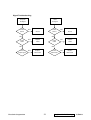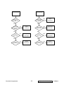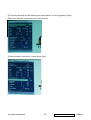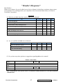
1
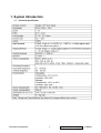
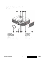
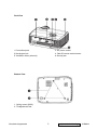
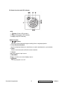
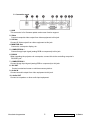
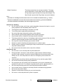
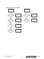
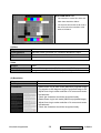
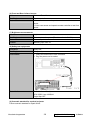
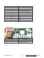
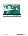
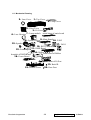
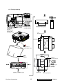
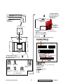
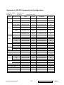
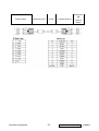
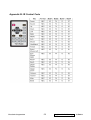
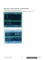
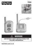
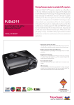
Service Manual
ViewSonic PJD6211
Model No. VS12618
DLP Projector
(PJD6211_SM Rev. 1b Nov. 2009)
ViewSonic® 381 Brea Canyon Road, Walnut, California 91789 USA - (800) 888-8583
Copyright
Copyright© 2009 by ViewSonic Corporation. All rights reserved. No part of this publication may be
reproduced, transmitted, transcribed, stored in a retrieval system, or translated into any language or
computer language, in any form or by any means, electronic, mechanical, magnetic, optical, chemical,
manual or otherwise, without the prior written permission of ViewSonic Corporation.
Disclaimer
ViewSonic makes no representations or warranties, either expressed or implied, with respect to the contents
hereof and specifically disclaims any warranty of merchantability or fitness for any particular purpose. Further,
ViewSonic reserves the right to revise this publication and to make changes from time to time in the contents
hereof without obligation of ViewSonic to notify any person of such revision or changes.
Trademarks
Optiquest is a registered trademark of ViewSonic Corporation.
ViewSonic is a registered trademark of ViewSonic Corporation.
All other trademarks used within this document are the property of their respective owners.
Revision History
Revision SM Editing Date
ECR Number
Description of Changes
Editor
1a
07/15/09
Initial Release (NO BOM by PE approval)
Sophia Kao
1b
11/04/09
Update Lamp hours reset procedure / RSPL
Sophia Kao
ViewSonic Corporation
Confidential - Do Not Copy
PJD6211
TABLE OF CONTENTS
1
System Introduction ................................ ................................ ................................ .............. 1
1.1
Technical Specification ..................................................................................................1
1.2
Location of features, Controls, and I/O .........................................................................2
1.3
PJD6211 Lamp Specification ........................................................................................7
1.4
PJD6211 System Block Diagram ................................................................................10
2
Firmware Upgraded Flow................................ ................................ ................................ .... 11
2.1
Setup Tool/Equipment ..................................................................................................12
2.2
Upgrading Procedure ...................................................................................................12
3
Machine Disassembly and Replacement ................................ ................................ ............ 16
3.1
Tools ............................................................................................................................... 16
3.2
Disassembly Procedure ............................................................................................... 17
3.3
Assembly FAN Module .................................................................................................24
3.4
4
Troubleshooting and Verifying the Repair ................................ ................................ ........... 26
4.1
Troubleshooting ............................................................................................................26
4.2
5
Verifying the Repair ......................................................................................................34
Connector Information ................................ ................................ ................................ ........ 40
5.1
Main Board .................................................................................................................... 40
5.2
5.3
5.4
6
Disassembly Lamp Module .......................................................................................... 25
The backside of Main Board ........................................................................................ 40
Ballast Board .................................................................................................................41
Power Board..................................................................................................................42
FRU (Field Replaceable Unit) List ................................ ................................ ...................... 43
6.1
Mechanical Drawing .....................................................................................................44
6.2
Packing drawing............................................................................................................46
7 Maintenance ................................ ................................ ................................ ....................... 49
Appendix A: RS-232 Command and Confi guration ................................ ................................ .... 50
Appendix B: IR Control Code ................................ ................................ ................................ ..... 52
Appendix C: How to reset the Lamp Hours ................................ ................................ ................ 53
8
Recommend Spare Parts List ...... ................................ ................................ ....................... 54
ViewSonic Corporation
Confidential - Do Not Copy
PJD6211
1. System Introduction
1.1 Technical Specification
ViewSonic Corporation
1
Confidential - Do Not Copy
PJD6211
1.2 Location of features, Controls, and I/O
A. Projector overview
Front View
1. Lens cap
7. Filter cover
2. Elevator button
3. Lens cap strap
4. Projection lens
8. Speaker
9.Focus ring
10.Zoom ring
5. Front IR remote control sensor
6. Ventilation holes (intake)
11.Control panel
12.Lamp cover
ViewSonic Corporation
2
Confidential - Do Not Copy
PJD6211
Real View
1. Connection ports
2. AC power socket
3. Kensington lock
5. Ventilation holes (exhaust)
4. Rear IR remote control sensor
6. Security bar
Bottom View
1. Ceiling mount (M4*6)
2. Tilt-adjustment feet
ViewSonic Corporation
3
Confidential - Do Not Copy
PJD6211
B. Button function and LED indicator
LED
Power (Power LED indicator)
1.
2. Temp (Temperature LED indicator)
3. Lamp (Lamp LED indicator)
Button function
4.
Keystone
Manually correct distorted images resulting from an angled projection.
5. Four directional buttons
Use four directional buttons to select items or make adjustments to your selection.
6. Enter
Enter to sub-menu and confirm the menu selection.
7. Source
Manually select an input source.
8. Menu/EXIT
Display or exit the on-screen display menus.
Power
9.
Turn the projector on or off.
ViewSonic Corporation
4
Confidential - Do Not Copy
PJD6211
C. Connection ports
1. USB
This connector is for firmware update and mouse function support.
2. Video
Connect composite video output from video equipment to this jack.
3. S-Video
Connect S-Video output from video equipment to this jack.
4. MONITOR Out
Connect to a computer display, etc.
5. COMPUTER IN 1
Connect image input signal (analog RGB or component) to this jack.
6. RS-232
When operating the projector via a computer, connect this to the controlling computer's
RS-232C port .
7. COMPUTER IN 2
Connect image input sign al (analog RGB or component) to this jack.
8. 12V OUT
Control a motorized screen or similar accessory device.
9. Audio IN
Connect an audio output from video equipment to this jack.
10. Audio OUT
Connect to a speaker or other audio input equipment.
ViewSonic Corporation
5
Confidential - Do Not Copy
PJD6211
D. Remote Control
ViewSonic Corporation
6
Confidential - Do Not Copy
PJD6211
1.3 PJD6211 Lamp Specification
Product Scope
The product is a lamp system consisting of a short arc burner within a reflector and electronic lamp
driver.
Type lamp
P-VIP 180/0.8 E20.8 open type
Identcode :
A 599 899
PT VIP O3 MID(180W)-UNISHAPE
Type driver
Identcode :
A581 105 (lock type,Gen5,VC,SL)
A581 111 (lock type,Gen5,VC,DL)
The lamp must be operated with the OSRAM lamp driver only.
Initial Characteristics
Input Voltage
Standby(non-operating)
Max. slew rate of input voltage
During switch on
tolerance
3 20…400V DC
120…400V DC
nominal
380V DC
30V μs
Input Current
Max. input voltage ripple
Max. input current ripple
Input Wattage
Input Wattage standby operation
0.55A
30Vpp@ 100-120Hz
1Arms@40 -300kHz
max.210W@180W lamp wattage
1, 7W @380V DC
Output Wattage
nominal
DIM mode
180W
1 60W
controlled by UART
Output current limitation
160W…180W
3.4A(RMS)
Ignition pulse
Ignition Phase Duration
Enable-Disable-Enable Cycle
Acoustic sound pressure level
typ.2.6kVpeak symm.
2.4 …3.5 kVpeak
typ.3. 5s
max.6 s
15 s minimum
typical acoustic sound pressure level 36 dB(A),maximum
38dB(A) at 25cm measuring distance; measured in ste ady
Acoustic sound power level
Switch-off lamp voltage
Cooling method
Thermal Protection
ViewSonic Corporation
3% 7
3% 6
in step with of 1/128 of nominal power
5%
state lamp operation 8
typical acoustic sound power level 32 dB(A) acc. to EN ISO
3744; measured in steady state lamp operation 7
140V
5V
forced air cooling at 1.5 m/s minimum
Tc1 switch point 90
5
7
Confidential - Do Not Copy
PJD6211
Safety Protections
The lamp connections are not mains isolated, The lamp
can be switched on via the Start Control Input signal(SCI).
A Flag Output signal indicates if the lamp has lit rightly. The
Start Control Input and the Flag Output are mains isolated.
Note:
7
Measured at real lamp load. Deviations will occur on all kind of artificial loads (e.g. resistor)
8
Measured with RGB waveform. The noise deviation from customer generated UNISHAPE
waveforms should be controlled by the offic ial approval process.
Attention for handling
Do not touch the lamp until it has cooled completely, because the lamp is very hot
during operation and immediately after turned off.
The lamp has to be fixed firmly to the base or socket.
Turn off the power supply during maintenance.
Do not hold the lamp except outer surface of the reflector.
Wear protective gloves and eyeglasses when handling the lamp.
Any unusual shock or vibration to the lamp should be avoided.
The lamp contains the mercury. It s breakage might cause mercury to flow out of the
reflector. Please manage provision at the customer’s product.
Do not pull the lead wire and plug by more than 24.5N.
Please be careful of handling the lamp because it is made of glass.
Please notice for keeping or handli ng the lamp, because there is a projection of this
lamp with reflector ahead.
Do not touch the bulb and the mirror area of the reflector.
Attention for use
Do not close or cover the lamp with any flammable stuff.
During operation, the lamp is under extreme ly high pressure. Please manage
provision at the customer ’s product to prevent fragments of bulb and mercury from
flowing out of it. If the lamp bursts in case of an emergency, the sound will be
occurred.
Lamp operation should be with the specified lamp dr iver and the system ONLY.
Do not look at the lamp directly during operations.
Do not expose your skin directly. We recommend to you to put on something for
protection for your skin. For example, long sleeve shirt, gloves, glassed and so on.
Do not modify the lamp and never use a lamp that has been modified.
Any unusual shock or vibration to the lamp should be avoided during operation.
Do not use any broken lamps.
Dispose of used lamps according to your local instruction.
Do not turn on the lamp while the sy stem is opened.
ViewSonic Corporation
8
Confidential - Do Not Copy
PJD6211
The lamp contains mercury. If the lamp bursts during operation ventilate the area
sufficiently to avoid inhaling harmful mercury fumes.
Use the lead below 200 C to prevent a deterioration of cladding clad of the
fluorocarbon resin.
The lead wire insulation clad shouldn ’t touch the reflector.
Exchange the lamp that has already passed the life time immediately.
ViewSonic Corporation
9
Confidential - Do Not Copy
PJD6211
1.4 PJD6211 System Block Diagram
ViewSonic Corporation
10
Confidential - Do Not Copy
PJD6211
2. Firmware Upgraded Flow
This chapter provides the information regarding relevant equipments and upgrading
procedure for firmware upgrade.
Note:
1. Please check the firmware and composer version before any f irmware upgrade
procedures. During firmware download period, plea se do not shut down PC or projector, this will
cause flash memory’s damage. And need to return the unit to manufacturer for flash memory
recovery.
2. Computer for operation must be Window XP or more advanced.
ViewSonic Corporation
11
Confidential - Do Not Copy
PJD6211
2.1 Setup Tool/Equipment
Computer
USB Cable (See the picture)
Power Cord
2.2 Upgrading Procedure
Installing [DLP Composer (TM) Lite]
1. Double-click [DLP Composer Lite v 9.2 Setup.exe].
2. Installation starts. Click [Next] to continue the installation process.
3. On the [License Agreement] screen, move the scroll bar on the right to the bottom, select [I
accept and agree to be bound by all the terms and conditions of this License Agreement],
and click Next to continue the installation process.
4. On the Select [Installation Type] screen, select [ALL] and click [Next] to continue the
installation process.
5. When the installation is finished, click [Finish] and reboot the PC. (A shortcut to DLP
Composer (TM) Lite is created on the desktop.)
ViewSonic Corporation
12
Confidential - Do Not Copy
PJD6211
USB Support - Installation (All Platforms)
This release includes support for a USB communications interface to DDP2 230/DDP2430
based projectors. The setup program includes the file s needed to install USB support . After
DLP Composer ™ Lite is installed, to install the USB support, choose the "Install DLP Device
USB Driver" icon under "DLP Composer ™ Lite" in your Start menu .
Follow the instruction on the screen to press any key and wait for the installation done.
And copy the file “FlashDeviceParameters.txt ” into the C:\ Program Files\ DLP Composer Lite
X.X
Operating procedure
1. Connect the Projector and PC via USB cable.
2. Double-click [DLP Composer (TM) Lite 9.2]. The following screen will appear.
3. Select [Edit]/ [Preferences]/ [Communications] to check USB in [Projector Interface].
4. Set the items on the [Vendor 0x451, Product 0x2000 ] of [USB Device Identification].
5. Click [OK].
ViewSonic Corporation
13
Confidential - Do Not Copy
PJD6211
6. Move the cursor to [Flash Loader] on the Project window of [DLP Composer Lite]. (The
[Flash Loader] screen will appear.)
7. Click [Browse] and select where the firmware [xxxxxxxxx.img] is for download.
8. Make sure [Skip Boot Loader Area] is with a check.
9. Press Menu and Power buttons constantly and then give power supply (switch power on).
Temp LED and Lamp LED will become amber. That indicates the projector is in the download
mode. At this moment, you can release these two buttons.
10. Click [Reset Bus] firstly to check if USB connects well.
11. Click [Start Download]. When the dialog box is displayed, click [Yes].
1. Click [Browse] and
select [*.img]
2. Put checkmark next to
[Skip Boot Loader Area] VALUE SETTING is 32KB
3. Click [Reset Bus] to confirm
the USB connection is ok.
4. Click [Start Download]
ViewSonic Corporation
14
Confidential - Do Not Copy
PJD6211
12. Wait for the Completion of Burning and then remove Power Cord and USB Burning Cord.
ViewSonic Corporation
15
Confidential - Do Not Copy
PJD6211
3. Machine Disassembly and Replacement
3.1 Tools
Item
Photo
Long Nose Nipper
Hex Sleeves 5mm
Screw Bit(+):107
Screw Bit(+):101
Screw Bit(+):102
Anti-static wrist strap
Anti-static wrist gloves
ViewSonic Corporation
16
Confidential - Do Not Copy
PJD6211
3.2 Disassembly Procedure
Warning
Put on the Static Electricity Ring when starting for repair.
Repair Environment suggest in Clean -room class 10000. Do not remove Optical
Engine or DMD panel outside the clean room. Please return the optical engine to
supplier if your repair condition can not meet the requirement.
While screwing or unscrewing screws, please keep the screwdriver straight. Keeping
screwdriver inclined will damage the s crew holes.
Please turn off the power before replacing any parts.
Please wait for the projector lamp cooling down and turn off the power before changing
it. Never touch or hit the lamp module when replacing the lamp.
When you replace the projector lamp, n ever touch the new lamp with your bare hands.
The invisible residue left by the oil on your hands may shorten the lamp life. Use
lint-free gloves or finger cots are recommended.
ViewSonic Corporation
17
Confidential - Do Not Copy
PJD6211
Step
Figure
Description
1
Press the power button to
shutdown the projector and
disconnect the power cord.
If the lamp is hot, please do
not start any procedure until
the projector lamp cools
down.
Flip the projector and
remove the lens cover.
2
1. Flip the projector on the
table.
J1635-3670-00
2. Remove the screws
J1635-A491-00*6 and
J1635-3670-00*1 on the
Bottom cover as shown.
J1635-A491-00*6
3
Rotate the Focus Ring by
forward sequence to take it
off from the unit.
ViewSonic Corporation
18
Confidential - Do Not Copy
PJD6211
Step
Figure
Description
4
1. Disconnect the FFC cable
and safety switch between
top cover and main board.
FFC Cable
2. Raise the Top Cover.
Safety switch
5
1. Loosen the one screw to
remove the safety switch.
J1635-3494-00*1
2. Remove four screws to lift
up the keypad board.
J1635-3720-00*4
6
82035-2520-00*8
J1635-3670-00*1
1. Remove all screws as
shown.
2. Remove the IO cover.
J1635-C072-00*2
ViewSonic Corporation
19
Confidential - Do Not Copy
PJD6211
Step
Figure
Description
7
1. Remove the five screws
on the Main Board.
J1635-B853-0A*5
2. Remove the metal sheet of
Main Board.
Note: The Back IR wire is
connected to Main Board
through the hole on metal
sheet.
Back IR wire
8
Remove the two Fan
Modules.
FAN 2
FAN 1
9
1. Show you what the
connector should be.
2. Remove all wires.
3. Remove the Main Board.
ViewSonic Corporation
20
Confidential - Do Not Copy
PJD6211
Step
Figure
Description
10
1. Loosen the two screws as
shown and remove all wires
on RS232 Board.
2. Remove the RS232
Board.
J1635-B853-0A*2
11
J1635-B853-0A*2
Loosen the two screws as
shown to remove the metal
sheet of Ballast.
Note: 2 wires have been
Note
connected to Ballast.
Disconnect these 2 wires
before remove the metal
sheet.
To Lamp
ViewSonic Corporation
To Power Board
21
Confidential - Do Not Copy
PJD6211
Step
Figure
Description
12
Release the four pillars by
Long Nose Nipper to remove
the Ballast.
13
1. Remove the screws on the
optical engine.
2. Remove the optical engine
module.
J1635-A491-00*3
14
J1635-3620-0A*1
J1635-D311-00*2
Loosen the two screws and
remove the lamp module
from optical engine.
Note: Those screws and
mesh are included in the
Lamp module.
ViewSonic Corporation
22
Confidential - Do Not Copy
PJD6211
Step
15
Figure
Description
1. Loosen the two screws
J1635-3660-00*4
J1635-3660-00*2
on the OE Fan.
2. Remove the Fan.
3. Loosen the four screws
on DMD Board.
4. Remove the heat sink
and DMD Board.
16
1. Loosen the two screws
on the Zoom Ring.
2. Remove the Zoom Ring.
3. Loosen the four screws
on the Lens.
4. Remove the Lens
J1635-D559-00*2
J1635-B730-0A*4
17
carefully.
1. Loosen the one screw and
J1635-3620-0A
remove the Lens Housin g.
Lens Housing
2. Loosen the screws on the
J1635-3620-0A*4
Power Board and then
remove the Power module
from Bottom Cover.
J1635-D420-0A*1
ViewSonic Corporation
23
Confidential - Do Not Copy
PJD6211
Step
Figure
18
Description
1. Remove Speaker Module.
J1635-3720-00*1
2. Loosen the screws and
remove front and back IR.
Speaker Module
3.3 Assembly FAN Module
Step
1
Figure
Description
Assemble FAN2(J2394-0101-01):
FAN Sponge*2
1. Paste the FAN PAD
(P4E38-1070-00) on the middle of
it.
2. Paste the FAN Sponge*2
(P4R38-1530-00) on the top and
bottom of it as picture shown.
FAN PAD
Assemble FAN1(J2394-0101-00):
2
Paste the FAN Sponge*2
(P4R38-1530-00) on the two edges
of it as picture shown.
FAN Sponge*2
ViewSonic Corporation
24
Confidential - Do Not Copy
PJD6211
3.4 Disassembly Lamp Module
As the projector operates over time, the brightness of the projector lamp gradually decreases
and the lamp becomes more susceptible to breakage. We recommend replacing the lamp if a
warning message is displayed. Do not attempt to replace the lamp yourself. Contact the
qualified service personnel for replacement.
Step
1
Figure
Description
Note: Turn on the projector. If the lamp does not turn on after
1. Turn off the projector.
the warm-up period, please reinstall the lamp.
2. If the projector is
installed in a ceiling
mount, remove it.
3. Unplug the power
cord.
4. Loosen the screw in
the side of the lamp
cover and remove the
cover.
5. Remove the screws
from the lamp
module, raise the
handle, and lift out the
module.
6. Insert the new lamp
module into the
projector and tighten
the screws.
7. Replace the lamp
cover and tighten the
screw.
8. Turn on the projector.
If the lamp does not
turn on after the
warm-up period, try
reinstalling the lamp.
9. Reset the lamp hour.
Refer to the “Setting”
menu.
ViewSonic Corporation
25
Confidential - Do Not Copy
PJD6211
4. Troubleshooting and Verifying the Repair
This chapter provides technicians with electronic background how to maintain the product.
Moreover, you can get the appropriate operation to solve some complicated problems of
component repairing and professional problems.
4.1 Troubleshooting
Warning
Do not directly look into the lens to avoid eyesight damages.
The projector is equipped with ventilation holes (intake) and ventilation holes (exhaust). Do
not block or place anything near these slots, or internal heat build -up may occur, causing
picture degradation or damage to the projector.
Confirm Software and hardware
(1) Confirm FW version is latest and lamp hours.
How to enter Engineering Mode?
-Open the Main menu and move the color bar to “setting” item, and then press right button
to enter sub-menu. Move down the color bar to “ Lamp Hours” item, press the direction keypad
following the actions below:
Right once, left twice, right three times, left four times ; Then you will enter the Engineering
Mode.)
Note: This FW version is just for reference.
ViewSonic Corporation
26
Confidential - Do Not Copy
PJD6211
(2) Confirm LED indicator
LED Type
Color
Status
Power LED Blue
Solid(LED× 1)
Lamp LED
Off
Off
Temp LED
Off
Off
Power LED Blue
Solid(LED× 2)
Lamp LED
Off
Off
Temp LED
Off
Off
Power LED Blue
Solid(LED× 2)
Lamp LED
Off
Off
Temp LED
Off
Off
Power LED Blue
Flash(LED× 2)
Lamp LED
Off
Off
Temp LED
Off
Off
Power LED Blue
Solid(Full brightness)
Lamp LED
Red
Solid
Temp LED
Red
Flash
Power LED Blue
Solid(Full brightness)
Lamp LED
Off
Off
Temp LED
Off
Off
Power LED Blue
Solid(Full brightness)
Lamp LED
Off
Solid
Temp LED
Off
Solid
Power LED Blue
Flash(Full
brightness)
Lamp LED
Red
Solid
Temp LED
Red
Solid
Power LED Blue
Solid(Full brightness)
Lamp LED
Red
Flash
Temp LED
Red
Off
Power LED Off
Off
Lamp LED
Red
Solid
Temp LED
Red
Solid
ViewSonic Corporation
Meaning
The projector is in standby mode.
Powering up
Normal operation
Power-down
The projector system has some problems with its
fans, so the projector cannot start up.
The lamp is in good condition and is projecting at
maximum brightness.
The lamp has reached its end of life and must be
changed soon. The lamp will continue to operate
until it fails. Change the lamp. If the lamp is off,
then the ballast will become malfunction.
The projector is shutting and the fan motor is
cooling the lamp for shutdown. Do not unplug the
power cord or turn the power off before the Lamp
LED changes to flashing. The fan mo tor will turn
off when the lamp has cooled.
Temperature is too high. The lamp will turn off.
The fan motor is cooling the lamp.
The lamp ignition failed. If temperature is too high,
the fans will cool the lamp.
27
Confidential - Do Not Copy
PJD6211
Note: Swapping modules that may be defective with others known to be good is generally an ideal way to
find the module responsible for the problem. A failure symptom is rarely caused by more than one module,
so you will not usually need to replace more than one to correct a particular failure. Whatever main board,
ballast, IR board, power board, lamp module or optica l engine are all suitable to check by swapping
modules.
ViewSonic Corporation
28
Confidential - Do Not Copy
PJD6211
Power Source Troubleshooting:
No Power
Source after
turning on
Fan failure after
turning on
NG
Check AC socket and
Replace AC
Check fan
connection
socket
connector
OK
NG
Reconnect fan
NG
Replace fan
NG
Replace
OK
Check
Safety Switch
NG
Replace power
Check
Fan
board or reinstall
OK
OK
NG
Check LED and keypad
Replace keypad
Check
Main board
and FFC
FFC
Main board
OK
Check 7 pin
Power output
NG
OK
Check
Fuse
OK
Replace
Replace
main board
power board
ViewSonic Corporation
NG
Replace fuse
29
Confidential - Do Not Copy
PJD6211
Fail to light up
Check LED
indication
No Volume
NG
Refer to LED
indicator and follow
indicative actions
Check
Speaker
OK
Check
Lamp life
NG
Replace
Speaker
OK
NG
Replace
Check
Main board
Lamp Module
NG
Replace
Main board
OK
Check PWR 380V
NG
Replace
Power board
output
OK
NG
Check Ballast
Replace
Ballast
OK
Check
Main board
NG
Replace
Main board
OK
Check CW
Rotation while
power on
ViewSonic Corporation
NG
Replace
CW module
30
Confidential - Do Not Copy
PJD6211
Signal Troubleshooting
Computer
Video
No Signal
No Signal
Check
Source
NG
Turn on
Check
Source
Source
OK
Check
Cable
ViewSonic Corporation
Turn on
Source
OK
NG
Replace
Check
Cable
Cable
OK
Check
Output signal
NG
NG
Replace
Cable
OK
NG
Replace
Check
Main board
Main board
31
NG
Replace
Main board
Confidential - Do Not Copy
PJD6211
Image abnormal
Color abnormal
Power on
again and reset
OSD
Check input
cable and signal
setting
OK
Check input
cable and signal
setting
NG
Adjust
Check Color
Wheel Index
Input signal
ViewSonic Corporation
Input signal
NG
Adjust Color
Wheel Index
OK
NG
Replace
Check
Main board
Main board
OK
Check
Optical Engine
Adjust
OK
OK
Check
Main board
NG
NG
Replace
Main board
OK
NG
Replace
Check
Optical Engine
Optical Engine
32
NG
Replace
Optical Engine
Confidential - Do Not Copy
PJD6211
Operation Function Troubleshooting
Button Failure
Remote Control
Failure
Check
Battery Level
NG
Replace
Check
Keypad and FFC
Battery
OK
Check
Remote Control
NG
Replace Keypad
and FFC
OK
NG
Replace
Check
Main board
Remote Control
NG
Replace
Main board
OK
Check
IR
NG
Replace
IR
OK
Check
Main board
ViewSonic Corporation
NG
Replace
Main board
33
Confidential - Do Not Copy
PJD6211
4.2 Verifying the Repair
After repairing projector (Dissembling and assembling projector), Repair center should verify
the quality of repaired unit.
(1) Check Logo
Check Logo is correct after power on projector.
(2) Signal test (Each I/O can function normally)
Connect all connector to the jacks one after the other to check whether each channel can
project normally.
I/O port
Monitor In (VGA)
Test Equipment
Standard Pattern generator (Ex. Quantum data)
Signal format
1024*768 60Hz
I/O port
Video
Test Equipment
Standard Pattern generator (Ex. Quantum data) or DVD player
Signal format
NTSC
I/O port
S-Video
Test Equipment
Standard Pattern generator or DVD player
Signal format
480i
I/O port
USB
ViewSonic Corporation
34
Confidential - Do Not Copy
PJD6211
Test Equipment
PC and Remote controller
Test method
1. Connect PC (laptop) VGA output to projector.
Set PC (laptop) output signal to projector
2. Connect projector USB to PC.
Press remote controller page up/down to scroll presentation file up and
down (ex Microsoft office series)
I/O port
Audio input
Test Equipment
Connect audio input to audio output of DVD player
Signal format
480i
(3) Operation test
Buttons operation
Button description
Test criteria
Power button
1. Mechanical motion (Up & Down) should be free from getting stuck
when pressing the button
2. Press “power” button and projector will switch on
Menu
1. Mechanical motion (Up & Down) should be free from getting stuck
when pressing the button.
2. Press Menu button can make projecto r function normally.
4-way button
1. Mechanical motion (Up & Down) should be free from getting stuck
when pressing the 4-way button.
2. Press 4-way button can be used to scroll through OSD (On Screen Display) menus and make adjustments.
Source
1. Mechanical motion (Up & Down) should be free from getting stuck
when pressing the button
2. Press Source button manually selects an input source
Foot adjuster operation
Foot adjuster.
Foot adjuster button
Test criteria
Foot adjusters should stretch downward smoothly by pressing the foot
adjuster buttons on the two sides
ViewSonic Corporation
35
Confidential - Do Not Copy
PJD6211
Zoom ring and Focus ring
Ring
Test criteria
Zoom ring
Mechanical motion of rotating Zoom ring to the end of right and left by
hand should be free from getting stuck.
Focus ring
The feeling of rotating Focus ring to the end of right and left by hand
should free from seizing
(4) Image Quality
Projected image size: 60 inches (diagonal length)
Zoom ring: Adjust zoom ring to wide (Maximum projection size)
VGA
I/O port
Monitor In (VGA)
Test Equipment
Standard Pattern generator (Ex. Quantum data)
Signal format
1024*768 60Hz
Projected image size
60” in diagonal length
Test criteria
Test Pattern
ANSI Brightness
Apparent color strip, bend and streak
corner on the projected image are not
allowable.
ViewSonic Corporation
36
Confidential - Do Not Copy
PJD6211
Extreme Gray-Scale
--0 represents full black, 255 represents full
white.
--Distinguishing the gray from black at the
value of 32 and the gray from white at the
value of 239 easily are acceptable.
Circular Geometry, Cross hatch and
Dots
1. The four lines of outer frame should
not only be existent but also
distinguishable.
2. The dots in the square should be
distinguishable.
Scaled Text ( Resolution)
1. Rotate Zoom ring to wide mode
(Maximum projected image)
2. Fix projector to set diagonal length of
projected image to 60”.
3. Adjust focus ring to make resolution of
4 corners and center are balanced.
4. Check the characters should be
recognized easily.
5. Rotate Zoom ring to tele mode
(Minimum projected image)
6. Adjust focus ring to make resolution of
4 corners and center are balanced.
7. Check the characters should be
recognized easily.
ViewSonic Corporation
37
Confidential - Do Not Copy
PJD6211
INFOCOMM SMPTE 133
1. The intervals of center thin white and
black bars should be distinct.
2. The squares around the small circle in
the center show the transition of full
white to full black.
S-Video
I/O port
S-Video
Test Equipment
Standard Pattern generator (Ex. Quantum data)&DVD player
Signal format
480i
Criteria
No apparent color deviation on the projected image
Video
I/O port
Video
Test Equipment
Standard Pattern generator (Ex. Quantum data)&DVD player
Criteria
No apparent color deviation on the projected image
(5) Resolution
I/O port
VGA
Test Equipment
PC
Test Method
1. Rotate Zoom ring to wide mode (Maximum projected image)
2. Fix projector to set diagonal length of projected image to 60 ”.
3. Adjust focus ring to make resolution of 4 corners and center
are balanced.
4. Check the characters should be recognized easily.
5. Rotate Zoom ring to tele mode (Minimum projected image)
6. Adjust focus ring to make resolution of 4 corners and center
are balanced.
7. Check the characters should be recognized easily.
ViewSonic Corporation
38
Confidential - Do Not Copy
PJD6211
(6) Front and Rear infrared sensor
Device
Front and Rear infrared
Test Equipment
Remote controller
Test method
1. Cover front sensor and operate remote controller to test rear
sensor
2. Cover rear sensor and operate remote controller to test front
sensor
(7) Brightness measurements
Test items
Brightness measurements
Test Equipment
Chroma automatic system (The alterna tive is CL-200)
Test method
Measure 9 points
Criteria
Marketing spec 20% off
(8) Safety test equipments
Test items
Safety test
Test Equipment
Safety analyzer
Test method
1. Clamp the metal shell of VGA connector
2. Plug the power cord to socket
Test criteria
GND 30A 3sec 100m
DCW 2506V 1sec 10000uA
Single Step OFF
(9) Cosmetic standard for repaired projector
Follow cosmetic standard for repair center.
ViewSonic Corporation
39
Confidential - Do Not Copy
PJD6211
5. Connector Information
This section provides each connector location on boards and function of each board. They will
be useful for your detecting the defective boards.
5.1 Main Board
No1
No2
Connector
Description
No 1
Front IR
No 2
Connect to RS232 Board
5.2 The backside of Main Board
No3
No4
No5
No7
No6
No8
No9
No10
No11
No12
No14
ViewSonic Corporation
No13
40
Confidential - Do Not Copy
PJD6211
Connector
Description
No 3
Speaker
No 4
Color Wheel control
No 5
Color Wheel Sensor
No 6
Ignite signal connected to Ballast
No 7
Lamp FAN
No 8
Thermal sensor
No 9
Safety switch
No 10
Main Board Power Supply
No 11
FAN2
No 12
FAN1
No 13
Back IR
No 14
Keypad control
5.3 Ballast Board
No2
No1
No3
Connector
Description
No 1
Lamp power supply
No 2
Ignite signal connected to Main board
No 3
High Voltage Power supply
ViewSonic Corporation
41
Confidential - Do Not Copy
PJD6211
5.4 Power Board
No2
No3
No1
Connector
Description
No 1
380V output for ballast
No 2
12V output for RS232 board
No 3
12V/5V output for Main board
ViewSonic Corporation
42
Confidential - Do Not Copy
PJD6211
6. FRU (Field Replaceable Unit) List
Introduction
This section is a list of all the FRU removal . Following the FRU table of contents is an enlarged
view of the entire projector, which shows the primary FRUs in the projector.
When working on the projector, use appropriate anti -static precautions such as anti -static mats,
wrist straps and grounded work surfaces. Failure to do this can destroy static -sensitive
components and make the product inoperable.
ViewSonic Corporation
43
Confidential - Do Not Copy
PJD6211
6.1 Mechanical Drawing
2. Lens Cover
1. Top Cover
4. Lamp Cover
5. Filter Cover
3. IO Cover
metal sheet of main board
6. Lens Housing 7. Lamp module
8. Optical Engine
15. Speaker
12. Front IR
heatsink of DMD Board
18. Power Board
9. Main Board
16. FAN2
10. RS232 Board
11. DMD Board
14. Ballast
metal sheet of Ballast
19. Bottom Cover
ViewSonic Corporation
17. FAN 1
metal sheet of IO Port
13. Back IR
20. Rear Foot
44
Confidential - Do Not Copy
PJD6211
EXPLODED PARTS LIST ( PJD6211 )
ViewSonic Model Number: VS12618
Rev: 1a
Item
ViewSonic P/N
Ref. P/N
Description
1
C-00009631
P4S84-4500
2
C-00009638
P4E34-4650-00
Lens Cover
1
3
C-00009633
P4S84-4530
IO Cover
1
4
C-00009630
P4R84-4520
Lamp Cover
1
5
C-00009635
P4R34-4600-00
Filter Cover
1
6
C-00009634
P4R34-4570-00
Lens Housing
1
7
RLC-050
P4R84-2400
Lamp Module
1
8
E-00009492
P4S84-2200
Optical Engine
1
9
B-00009697
P4S84-7100
Main Board
1
10
B-00009701
P4R47-6101
RS232 Board
1
11
B-00009703
P4D47-6100
DMD Board
1
Top Cover
Q'ty
1
12
B-00008158
P3747-5101
FIR Board
1
13
B-00009700
P4R47-5101
BIR Board
1
14
B-00009702
P4R84-9000
Ballast
1
15
E-00009495
J2413-0092-00
Speaker
1
16
M-00008342
J2394-0101-01
Fan2
1
17
M-00008212
J2394-0101-00
Fan1
1
18
B-00009698
P4U84-8100
Power Board
1
19
C-00009632
P4R84-4510
Bottom Cover
1
20
M-00008344
P4E38-1570-00
Rear Foot
1
ViewSonic Corporation
45
Confidential - Do Not Copy
PJD6211
6.2 Packing drawing
1. LB P1638-5007-00
Warning lb
2. P2838-5001-00
加貼底蓋位置(如圖)
3.
如圖示位置加貼
5mm
5mm
RCT YY WW XXXXX July 2008
P4S38-5000-00
5mm
PJD6211/DLP PROJECTOR
PROJECTEUR DLP/DLP投影機/DLP投影機
MODEL(MODÈLE/產品型號/產品型號):VS12618
INPUT(ENTRÉE/輸入/輸入):AC 100-240V~ 50-60Hz 2.5A
PJD6211/DLP PROJECTOR
PROJECTEUR DLP/DLP投影機/DLP投影機
MODEL(MODÈLE/產品型號/產品型號):VS12618
INPUT(ENTRÉE/輸入/輸入):AC 100-240V~ 50-60Hz 2.5A
3mm
P4S38-5000-00
UL LB
4. J4238-R815-01
MAC ADDRESS LB 5. P4S38-5000-00
序列號貼紙廠內列印
加貼底蓋位置(如圖)
RCT:固定碼(PJD6211) 如圖示位置加貼
YY:年的后兩位
WW:周別
XXXXX:流水碼
同機種依次順延
JULY 2008: 月 年
請用透明膠帶按照上圖貼好
EPE
7. P4R39-7001-00
鏡頭在此處
Birdllogo
6.P1238-R504-00
依照對位線如圖方式加貼
淋膜袋
主線物料
CARTON
8. P4S39-6000-00
33
2
2
9. J4039-R128-01
乾燥劑置入
CARTON中
1
鏡頭在此處
請按照以上折疊順序以此折好
ViewSonic Corporation
46
PAD
10. P8339-6900-00
Confidential - Do Not Copy
PJD6211
SHEET
11. P4R39-4800-00
QG
12. P4R39-4000-00
16.
P4S39-6000-00印
刷面請以實物為准
此處僅供參考
CD
13. P4R39-A000-00
入膠袋后放入
卡板中間槽位中
LB
J4238-R801-00
根據電源線類型
不同分別列印
USA/UK/EU/AU等
HDPE BAG
14. 04039-R157-01
MAC ADDRESS LB
主線提供
如圖示加貼,與下面框線
距離3mm,左邊對齊框線
CARTON LB
17. J4238-5006-00
CARTON LB
J4238-5006-00 廠內列印內容具體內容如下.
Projector PJD6211 (Code
)
UPC
Projector PJD6211
VS12618
所有線材和電池一起放入
15. J4039-R184-01後放於此處
遙控器放在最上面
RCT
RC
D-SUB CABLE
J2552-0110-00
RCA/Y CABLE
02552-0075-00
REMOTE CONTROL
視POI需求
S-VIDEO CABLE
J2552-0092-01
POWER CORD
J2552-0109-00
為生產年月日
"RC"為出貨向別
M: VSA
E: VSE
P: VSI
G: VSCN
PHONE CABLE
J2552-0110-00
注明﹕線材視POI選配
ViewSonic Corporation
RCTYYWWXXXXX (YY: year, WW: week)
RCT表示PJD6211
XXXXX為流水碼
CODE128
47
Confidential - Do Not Copy
PJD6211
PACKING PART LIST ( PJD6211 )
ViewSonic Model Number: VS12618
Rev: 1a
Item
1
2
3
4
5
6
7
8&16
9
10
11
12
13
14
15
16
17
ViewSonic Corporation
ViewSonic P/N
NA
NA
NA
NA
NA
NA
P-00009637
P-00009636
P-00008880
P-00008722
NA
DC-00009666
DC-00009667
P-00008410
P-00008794
NA
NA
Ref. P/N
P1638-5007-00
P2838-5001-00
P1638-5010-00
J4238-R815-01
P4S38-5000-00
P1238-R504-00
P4R39-7001-00
P4S39-6000-00
J4039-R128-01
P8339-6900-00
P4R39-4800-00
P4S39-4000-00
P4R39-A000-00
J4039-R157-01
J4039-R184-01
P0N38-5013-00
J4238-5006-00
48
Description
LB
WARNING LB
LB
SERIAL LB
UL LB
LB
EPE
CARTON
DESICCANT
PAD
SHEET
QG
CD-ROM
PE.BAG
PE.BAG
CARTON LB
LB
Q'ty
1
1
1
1
1
1
1
1
1
1
1
1
1
1
1
1
1
Confidential - Do Not Copy
PJD6211
7. Maintenance
The projector needs proper maintenance. You should keep the lens clean as dust, dirt
or spots will project on the screen and diminish image q uality. If any other parts need replacing,
contact your dealer or qualified service personnel. When cleaning any part of the projector,
always switch off and unplug the projector first.
Warning:
Never open any of the covers on the projector. Dangerous electrical volta ges inside the projector
can cause severe injury. Do not attempt to service this product yourself. Refer all servicing to
qualified service personnel.
Cleaning the Lens
Gently wipe the lens with lens cleaning paper. Do not touch the lens with your hands.
Cleaning the Projector Housing
Gently wipe with a soft cloth. If dirt and stains are not easily removed, use a soft cloth damped
with water, or water and neutral detergent, and wipe dry with a soft, dry cloth.
Cleaning the Filter Cover
The filter cover, which is located at the side of the projector, should be cleaned after every 100
hours of use. If it is not cleaned periodically, it can become clogged with dust and prevent the
projector from being ventilated properly. This can cause over heating and damage the projector.
To clean the filter cover:
1. Switch the projector off and unplug the AC
power cord from the wall socket.
2. Remove the filter cover as the
illustration shown.
3. Clean the filter cover.
To clean the filter cover, you are advised to
use a small vacuum cleaner designed for
computers and other office equipment.
If the filter cover is torn, replace it.
4. Replace the filter cover.
5. Attach the filter cover.
6. Plug the power back into the projector.
ViewSonic Corporation
49
Confidential - Do Not Copy
PJD6211
8. Recommended Spare Parts List
RECOMMENDED SPARE PARTS LIST (PJD6211)
ViewSonic Model Number: VS12618
Serial No. Prefix: RCT
Rev: 1b
Item
1
2
4
5
6
7
8
9
10
11
12
13
14
15
16
17
18
19
20
21
22
23
24
25
26
27
28
29
30
31
32
33
34
Category
Accessories:
[Adapter, Remote
Controller, Power
Cord, External
Cables]
PC Board
Assembly: [All
PCBA]
Cabinets:
[Front Bezel, All
Covers, Base
Assembly]
Cables: [All
internal
Cables/wires]
Part Name
LAMP
Remote Controller
Power Cord
Power Cord
Power Cord
Power Cord
Power Cord
Power Cord
RS232 Cable
RGB to component adapter
Signal Cable (VGA)
Main Board
Power Board
Key Pad
FIR Board
BIR Board
RS232 Board
Ballast
DMD Board
Cw Sensor Board
Lamp Cover
Top Cover
Bottom Cover
IO Cover
Lens Housing
Filter Cover
ZOOM RING
FOCUS RING
Lens Cover
Description
LAMP-MODULE-ASY-180W-SPARE PART_VPD-X5400_ROHS
BATTERY_MODULE_SPARE PARTS_VIEWSONIC_VPD-X5400_ROHS(with package)
POWER CORD (AUSTRALIA)._(SAA)YP-35/YC-12_YUNG LI_ROHS
POWER CORD(CHINA)._YP-03/YC-12_YUNG LI_ROHS
POWER CORD(EUROPE)._YP-22/YC-12_YUNG LI_ROHS
POWER CORD (SOUTH AFRICA)._YP-80/YC-12_YUNG LI_ROHS
POWER CORD(UK)._YP-61/YC-12_YUNG LI_ROHS
POWER CORD(USA)._UL(YP-12/YC-12)_YUNG LI_ROHS
DB9P TO DB9P CABLE_L1500_P35251A-05_PAN_ROHS
VGA-15P-6P CABLE_P4724-08_PAN_ROHS
VGA-15P CABLE_P3842-06_PAN_ROHS
MAIN_DIP_PCB_ASY_SPARE PARTS_VPD-X5500_ROHS
POWER BOARD_SPARE PARTS_VPD-X5501_ROHS
KEYPAD_DIP_PCB_ASY_VPD-X5500_ROHS
FIR_DIP_PCB_ASY_PD-X702_ROHS
BIR_DIP_PCB_ASY_P4R/VPD-X5400_ROHS
RS232_DC_DIP_PCB_ASY_VPD-X5400_ROHS
OSRAM-BALLAST-180W-SPARE PART_VPD-X5400_ROHS
DMD450_DIP_PCB_ASY_TPD-S5500_ROHS
CW_DIP_PCB_ASY_PD-S550_ROHS
LAMP COVER_SPARE PARTS_VPD-X5400_ROHS
TOP COVER_SPARE PARTS_VPD-X5500_ROHS
BOTTOM COVER_SPARE PARTS_VPD-X5400_ROHS
I/O COVER_SPARE PARTS_VPD-X5500_ROHS
LENS HOUSING_VPD-X5400_00_NO PAINTING_ROHS
FILTER COVER_VPD-X5400_00_NO PAINTING_ROHS
ZOOM RING_VPD-X5400_99_FOR PAINTING_ROHS
RINGS SPARE PARTS_VPD-X5400_ROHS
LENS CAP_TPD-X5500_00_NO PAINTING_ROHS
ECR/ECN
Wire
CONN FPC_0.5PITCH_20PIN_A20240C3344NB_ENTERY_BOTTOM_ROHS(top cover to main board)
Wire
Wire
Wire
WIRE ASSY_CON-SW_1102003-202_MSK_ROHS(top cover to main board)
WIRE CON-CON_1102003-182_MSK_4PIN_L120MM_1571#28_ROHS(color wheel to main board)
WIRE CON-CON_1102003-236_MSK_4PIN_L105MM_1571#28_ROHS(color wheel to main board)
VS-E090256 Added on 10/15/09
VS-E090251 Added on 10/15/09
ViewSonic P/N
RLC-050
A-00008487
A-00008060
A-00008056
A-00008057
A-00008233
A-00008058
A-00008059
CB-00009062
CB-00008906
CB-00008710
B-00009697
B-00009698
B-00009699
B-00008158
B-00009700
B-00009701
B-00009702
B-00009703
B-00009081
C-00009630
C-00009631
C-00009632
C-00009633
C-00009634
C-00009635
C-00009636
C-00009637
C-00009638
Ref. P/N
P4R84-2400
P4R84-3000
J2552-0053-00
J2552-0106-00
J2552-0107-00
J2552-0056-01
J2552-0108-00
J2552-0109-00
J2552-0208-00
J2552-0212-00
J2552-0072-03
P4S84-7100
P4U84-8100
P4S47-7100
P3747-5101
P4R47-5101
P4R47-6101
P4R84-9000
P4D47-6100
P0F47-5100
P4R84-4520
P4S84-4500
P4R84-4510
P4S84-4530
P4R34-4570-00
P4R34-4600-00
P4R34-4550-99
P4R84-4540
P4E34-4650-00
CB-00009052
J2471-0300-00
CB-00009055
CB-00009053
CB-00009158
J2595-0366-00
J2595-0325-00
J2595-0368-01
35
36
37
38
Wire
WIRE CON-CON_1102003-231_MSK_10PIN-2*8PIN_L115MM_1007#24_ROHS(power board to main board)
CB-00009054
J2595-0407-00
Wire
Wire
Wire
WIRE CON-CON_1102003-98_MSK_2PIN_L140MM_1015#22_ROHS(power board to ballast)
WIRE ASSY_CON-SW_1102003-202_MSK_ROHS(top cover to main board)
WIRE CON-CON_1102003-203_MSK_4PIN_L115MM_1571#28_ROHS(IR to main board)
CB-00008469
CB-00009055
CB-00009056
J2595-0218-00
J2595-0366-00
J2595-0367-00
39
40
41
42
43
44
45
46
47
48
49
50
51
52
53
54
55
56
57
58
59
60
61
62
63
64
65
66
67
68
69
70
71
72
73
74
75
76
77
Wire
WIRE LAMP-BALA_01800138R_AVERTRONICS_2PIN_L135MM_3239V#20_ROHS(Ballast to Lamp)
Wire
Wire
Wire
Wire
Wire
Qucik Start Guide (QSG)
User's Guide (CD ROM)
Label / Sticker
Optical Engine
Optical Engine
Color Wheel
Lens
Lens
Speaker
Screw
Screw
Screw
Screw
Screw
Screw
Screw
Screw
Screw
Screw
Screw
Fan
Fan
Fan
Rear Foot
Carton
Pad
Foam
Pe Bag
Pe Bag
Desiccant
Metal Dome
FAN PAD
FAN SPONGE
WIRE CON-MOTOR PROTECTOR_2PIN_L65MM_1332#24_ROHS( 温控开关)
WIRE CON-CON_1102003-207_MSK_3PIN_L185MM_1571#28_ROHS(RS232 Board to main board)
WIRE CON-CON_1102003-235_MSK_3PIN_L185MM_1571#28_ROHS(RS232 Board to main board)
WIRE CON-CON_1102003-206_MSK_5PIN_L95MM_1571#28_ROHS(Ballast to main board)
WIRE CON-CON_1102003-205_MSK_4PIN_L130MM_1571#28_ROHS(power board to RS232 board)
QG_VIEWSONIC_VPD-X5500_GLOBAL_ROHS
CD ROM_VIEWSONIC_VPD-X5400_GLOBAL_ROHS
C/T LB_NO BRAND_GLOBAL_ROHS
OPTICAL ENGINE ASY(WITHOUT LAMP)SPARE PARTS_VPD-X5500_ROHS
OPTICAL ENGINE ASY(WITHOUT LAMP)9G SVDMD SPARE PARTS_VPD-X5500_ROHS(for 9G)
COLOR-WHEEL MODULE_SPARE PARTS_VDP-X5400_ROHS
LENS ASY_SPARE PARTS_VPD-X5600_ROHS
LENS ASY_SPARE PARTS_VPD-X5400_ROHS(for 9G)
SPEAKER_P28KC16-9-7JS-2_VECO_ROHS
HEXAGON-HEAT-BOLT-4_MPD-S651_3M_ROHS
SCREW_TP_3_10_A_2_D=5.5_BLACK_NONE_ROHS
SCREW_M_3_8.0_E_1.5_D=5.0_BLACK_NL_ROHS
SCREW-WASHER_TP_2_4_D_1_D=3.2_NI_NONE_SUS_ROHS
SCREW_M_2_5_A_D=3_A0.8_BLACK_HEAT-TREATMENT_ROHS
SCREW-WASHER_M_4_6_A_2.6_D=7_ZN_NONE_SUS_ROHS
SCREW-WASHER_TP_3_6_D_2.6_D=5.4_ZN_NONE_SUS_ROHS
SCREW-WASHER._TP_3_10_D_7_D=5.3_NI_NONE_SUS_ROHS
SCREW+WASHER_M_3_6_D_2_D=5.3_ZN_NONE_SUS_ROHS
SCREW_TP_1.8_3_E_0.3_D=4.5_BLACK_NONE_ROHS
SCREW_TP_2_10_A_1.2_D=3.5_NI_NONE_ROHS
FAN_3110RL-04W-S59-F00(L=60MM)_NMB_ROHS
FAN_3110RL-04W-S59-F03(L=60MM)_NMB_ROHS
FAN_BFB0512VHD-8L07(L=65MM)_DELTA_ROHS
FOOT-REAR_TPD-X5500_ROHS
CARTON_VIEWSONIC_VPD-X5500_GLOBAL_ROHS
PAD_PREMIER_PD-S650_GLOBAL_ROHS
EPE_NO_VPD-X5400_FOR BODY WITHOUT BAG_ROHS
PE BAG._NO BRAND_298MM*190MM_ROHS
PE BAG._NO BRAND_GLOBAL_ROHS
DESICCANT_NO BRAND_50G-CLAY_ROHS
METAL DOME P4R_VPD-X5400_ROHS
FAN PAD_TPD-X5500_ROHS
FAN SPONGE P4R_VPD-X5400_ROHS
Documentation:
[Quick Start
Guide, CD Rom;
Electronic
Components:
[Optical Engine,
Speaker, Color
Wheel]
Hardware: [Screw,
Bracket, Hinge]
Miscellaneous:
[Switch, Fan,
Rubber Foot,
Logo]
Packing Material:
[Box, Foam, Bags]
Plastics: [Pedestal,
Plate, Button, etc.]
VS-E090206 Replaced on 10/15/09
VS-E090258 Replaced on 10/15/09
CB-00009057
J2595-0277-00
CB-00009058
CB-00009059
CB-00009156
CB-00009060
CB-00009061
DC-00009666
DC-00009667
DC-00008794
E-00009492
E-00009552
E-00009493
E-00009494
E-00009652
E-00009495
HW-00008066
HW-00008860
HW-00008861
HW-00008043
HW-00008862
HW-00008863
HW-00008864
HW-00008345
HW-00008865
HW-00008866
HW-00008867
M-00008212
M-00008342
M-00008343
M-00008344
P-00009636
P-00008722
P-00009637
P-00008794
P-00008410
P-00008880
PL-00008690
PL-00008691
PL-00008692
J2595-0346-00
J2595-0371-00
J2595-0371-01
J2595-0370-00
J2595-0369-00
P4S39-4000-00
P4R39-A000-00
J4238-5069-00
P4S84-2200
P4S84-2201
P4R84-2600
P4T84-6200
P4R84-6200
J2413-0092-00
82035-2520-00
J1635-3670-00
J1635-C072-00
J1635-3720-00
J1635-2250-00
J1635-D420-0A
J1635-3620-0A
J1635-A491-00
J1635-B853-0A
J1635-D559-00
J1635-3494-00
J2394-0101-00
J2394-0101-01
J2394-0117-00
P4E38-1570-00
P4S39-6000-00
P8339-6900-00
P4R39-7001-00
J4039-R184-01
J4039-R157-01
J4039-R128-01
P4R38-1510-00
P4E38-1070-00
P4R38-1530-00
Ref. NO
Compatibility
Location
Second source
Remark 1: Above listed items are examples, supplier can expand the rows to add more necessary items.
Remark 2: All revised RSPLs with newly added items or any change made should be highlighted and correlated with the ECN/ECR approved by ViewSonic Corporation. This is to eliminate repeated cross checks of each item between this version and prior versions.
ViewSonic Corporation
50
Confidential - Do Not Copy
PJD6211
Appendix A: RS-232 Command and Confi guration
Baud Rate: 19200
Data Bit: 8
Name
Parity Bit: none
Stop Bit: 1
Assign Port: COM1
Operation type
CRS
Header
Command
Response
ON
BE,EF,10,05,00
C6,FF
11,11,01,00,01,00
06
OFF
BE,EF,03,06,00
DC,DB
69,00,00,00,00,00
06
(Analog RGB)
BE,EF,03,19,00
19,29
01,47,05,CC,CC,00
06
YCbCr
BE,EF,03,19,00
89,E8
01,47,05,CC,CC,00
06
S-Video
BE,EF,03,19,00
E8,69
01,47,05,CC,CC,00
06
Video
BE,EF,03,19,00
78,A8
01,47,05,CC,CC,00
06
HDTV (Y-Pb-Pr)
BE,EF,03,19,00
DA,A8
01,47,05,CC,CC,00
06
Menu
BE,EF,02,06,00
E9,D3
30,00,00,00,00,00
06
Up
BE,EF,02,06,00
6D,D2
34,00,00,00,00,00
06
Down
BE,EF,02,06,00
0B,D2
32,00,00,00,00,00
06
Left
BE,EF,02,06,00
DA,D3
33,00,00,00,00,00
06
Right
BE,EF,02,06,00
38,D2
31,00,00,00,00,00
06
On
BE,EF,03,06,00
EF,DB
6A,00,00,00,00,00
06
Off
BE,EF,03,06,00
3E,DA
6B,00,00,00,00,00
06
Auto
On
BE,EF,03,06,00
89,DB
6C,00,00,00,00,00
06
Source
Off
BE,EF,03,06,00
58,DA
6D,00,00,00,00,00
06
Source
BE,EF,02,06,00
57,D0
2E,00,00,00,00,00
06
Auto-Sync
BE,EF,02,06,00
86,D1
2F,00,00,00,00,00
06
Blank Screen(Video)
BE,EF,02,06,00
DF,DF
66,00,00,00,00,00
06
Keystone
BE,EF,02,06,00
3D,DE
64,00,00,00,00,00
06
Up
BE,EF,03,06,00
10,DB
65,00,00,00,00,00
06
Down
BE,EF,03,06,00
23,DB
66,00,00,00,00,00
06
Volume +
BE,EF,02,06,00
F1,DE
68,00,00,00,00,00
06
Volume -
BE,EF,02,06,00
20,DF
69,00,00,00,00,00
06
Image
BE,EF,03,06,00
F2,DA
67,00,00,00,00,00
06
Aspect Ratio
BE,EF,03,06,00
0D,DA
68,00,00,00,00,00
06
Factory Reset
BE,EF,03,06,00
6B,DA
6E,00,00,00,00,00
06
Lamp Hour
BE,EF,03,06,00
BA,DB
6F,00,00,00,00,00
Lamp Hour
Firware Version
BE,EF,03,06,00
D5,D9
70,00,00,00,00,00
Version
Power
Computer
Source
OSD
Composite
ECO
Keystone
Volume
ViewSonic Corporation
51
Confidential - Do Not Copy
PJD6211
03:Projector
System Status
BE,EF,03,06,00
04,D8
71,00,00,00,00,00
ON
(Normal
Mode)
ViewSonic Corporation
52
Confidential - Do Not Copy
PJD6211
Appendix B: IR Control Code
ViewSonic Corporation
53
Confidential - Do Not Copy
PJD6211
Appendix C: How to reset the Lamp Hours(OK)
(1) Press “Menu” button to open the Main menu.
(2) Move color bar to “setting” item and then press right button to enter sub -menu.
(3) Move down the color bar to “Lamp Hours” item.
ViewSonic Corporation
54
Confidential - Do Not Copy
PJD6211
(4) Press the direction keypad following the actions below to enter engineering mode :
Right once, left twice, right three t imes, left four times.
(5) Move down the color bar to “Lamp Reset” item.
ViewSonic Corporation
55
Confidential - Do Not Copy
PJD6211
(6)Press left button to select “yes” to reset Lamp Hours .
(7)Then the Lamp Hours would reset to 0 hours.
ViewSonic Corporation
56
Confidential - Do Not Copy
PJD6211
* Reader’s Response*
Dear Readers:
Thank you in advance for your feedback on our Service Manual, which allows continuous improvement
of our products. We would appreciate your completion of the Assessment Matrix below, for return to
ViewSonic Corporation.
Assessment
A. What do you think about the content of this Service Manual?
Unit
Excellent
Good
Fair
Bad
1. System Introduction
2. Firmware Upgraded Flow
3. Machine Disassembly and Replacement
4. Troubleshooting and Verifying the Repair
5. Connector Information
6. FRU (Field Replaceable Unit) List
7. Maintenance
8. Recommend Spare parts List
B.
Are you satisfied with this Service Manual?
Item
Excellent
Good
Fair
Bad
1. Service Manual Content
ʳ
ʳ
ʳ
ʳ
2. Service Manual Layout
ʳ
ʳ
ʳ
ʳ
3. The form and listing
ʳ
ʳ
ʳ
ʳ
C. Do you have any other opinions or suggestions regarding this service manual?
Reader’s basic dada:
Name:
ʳ
Title:
ʳ
ʳ
Company:
Add:
Tel:
ʳ
ʳ
Fax:
ʳ
ʳ
E- mail:
After completing this form, please return it to ViewSonic Quality Assurance in the USA at facsimile
1-909-839-7943.
ViewSonic Corporation
57
Confidential - Do Not Copy
PJD6211