1
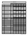
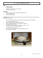
Service Instructions
Centurion Qex
CeramPress Qex
Neytech Qex
DENTSPLY Ceramco
Yucaipa, CA
Table of Content
Chapter
Title
1
1.1
1.2
General Information
Safety Information
Repair Devices and Tools
2
2.1
Repair Parts
Repair Part List
3
3.1
3.2
3.3
3.4
Circuit Diagrams and Drawings
Wiring Diagram
Block Circuit Diagram
Component Mounting Diagram of Control PC
Pneumatic Diagram
4
4.1
4.2
Elimination of Errors
Troubleshooting
Error Messages
5
5.1
5.2
5.3
5.4
Checks
Check of
Check of
Check of
Check of
6
6.1
6.2
Settings
Calibration of Muffle Temperature
Calibration of Vacuum
7
7.1
7.1.1
7.1.2
7.1.3
7.1.4
7.1.5
7.2
7.2.1
7.2.2
7.2.3
7.2.4
Repair Instructions
General Repair Information
Exchange of Computer PC Board
Exchange of Key Pad
Exchange of Display
Exchange of Encoder
Exchange of Memory Card PCB
Mechanical
Exchange of Thermocouple
Exchange of Solenoid Valves
Exchange of Muffle
Exchange of Motor
Temperature (PCB)
Temperature (Muffle)
Vacuum and Release Time
Motor Position
9363133 rev. C 0704
2
Table of Content Cont.
8
8.1
8.2
8.3
8.4
Others
Reset of Firing Cycle
Reset of Memory
Centurion/Cerampress Selection
Test Programs
9
9.1
Service
Product Service Information
9363133 rev. C 0704
3
1.1 Safety Information
Repair work must only be performed by service technicians authorized by DENTSPLY Ceramco!
The unit must only be operated with original spare parts and accessories. Only in this way the
performance data provided in the instructions for use can be achieved and the required operational safety
is ensured.
! !! During service work the unit must be unplugged from electrical source!!
Exception:
During setting and adjustment work the unit must be switched on.
These types of work must be carried out extremely carefully since live components may be touched!
Prior to touching any electric components a metal part should be touched with the hand to avoid
electrostatic charging of the human body. We recommend to wear an earthing strap while working on the
electronic equipment of the unit.
The PC boards must only be stored and shipped in antistatic material (e.g. aluminum foil).
If possible, use original packing.
9363133 rev. C 0704
4
1.2 Repair Devices and Tools
Device/Tool
Card Holder with Service Card,
Special Card & Calibration Card
Digital Vacuum Meter (absolute)
Where Used
To activate service functions
Source
DENTSPLY Ceramco
Vacuum Adjustment and Control
Temperature Meter (Type-R)
To measure muffle temperature
GDH 12AN Greisinger
Electronic
Extech 421508
Calibration Platform
To calibrate furnace temperature
DENTSPLY Ceramco
Potentiometer Adjustment Tool
To change potentiometer settings for
temperature or vacuum
To inject a temperature for
calibration purposes
Electronic Store
Temperature/Calibrator (Type-R)
Omega Engineering CL25
9363133 rev. C 0704
5
2.1 Repair Parts
Item No. Description
1
Membrane Switch; Cent. Qex
2
Knob; Encoder Qex
3a
Control Drawer; Qex
Control Drawer; Qex
3b
Effective date code 0650
Control Drawer; Qex
3c
Effective date code 0638
4
Serv; PCB Assy, Encoder
5a
Serv; Display Assy, Qex
Serv; PCB Assy. Display
5b
Effective date code 0703
Serv; PCB Assy. Display
5c
Effective date code 0637
6
Triac; 25A, 400V
7a
Serv; PCB Assy, Control
Serv; PCB Assy. Control
7b
Effective date code 0703
Serv; PCB Assy. Control
7c
Effective date code 0637
8
Serv; PCB Assy, Card, Qex
9
Serv; Valve Kit, Qex
10
Serv; Muffle Assy
11
Muffle Retaining Ring
12
Serv; Thermocouple
13
Muffle Termination Kit
14
Air Cylinder
15
Upper Pivot Arm
16
Lower Pivot Arm
17
Fan Axial
18
Rod; Plunger
19
Serv; Motor Assy, Qex
20
Rod; Seal
21
Door; Oring
22
Door Machined
23
Door Insulation
24
Cap Door Insulation
25
Slide Shelf
26
Column Cover
27
Top Enclosure
28
Bottom Wraparound
29a
Counter Balance
Counter Balance, Adjustable
29b
Effective date code 0150
30
Filter, EMI
31
Inductor DC Choke
Neytech Qex
Centurion Qex
Cerampress Qex
120V
230V
120V
230V
120V
230V
9494305 9494306 9494310 9494311 9494400 9494401
9354418
9355028
9494215
R9495154
---
--R9495154
R9494314
R9494376
R9495146
---
R9495154
---
R9495154
---
---
R9495154
---
R9495154
R9495146
---
R9495146
---
--R9495146
--R9495146
--R9495146
9303015
R9494307 R9494308 R9494312 R9494313 R9494389 R9494390
R9495138
---
--R9495145
R9494322
9494303
9494317 9494318
9492902
9494302
9493062 9493062
9352087
9492893
9492959
--------9494304
----9357071
9361065
9494293 9494293
----9361081
9494263
9494251 9494251
9494214
9352040
9352102
-----
9320120
9310045
R9495138
---
R9495138
---
---
R9495145
---
R9495145
9494090
9494091
9494317
9494318
9493680
9493680
9493062
9493062
9493662
9353066
9493662
9353066
-----
-----
9357106
9357106
---
---
9494028
9494027
9494028
9494027
9494293
---
9494293
---
9494246
9494246
9494251
9494251
-----
9320120
9310045
-----
9320120
9310045
9363133 rev. C 0704
6
2.1 Repair Parts Cont.
9363133 rev. C 0704
7
2.1 Repair Parts Cont.
Centurion Qex
Neytech Qex
Top Enclosure
Mtg. Brkt.
12
Vacuum Chamber
10
13
11
9363133 rev. C 0704
8
2.1 Repair Parts Cont.
Cerampress Qex
18
12
20
14
17
13
12
Connect to tabs
inside chamber
10
11
9363133 rev. C 0704
9
2.1 Repair Parts Cont.
Cerampress QEX
21
22
27
Heatshield
24
23
26
25
Centurion QEX
Neytech QEX
28
27
9363133 rev. C 0704
10
2.1 Repair Parts Cont.
Shoulder Bolt 1/2” x 5/16”
Screw 10-32
Bronze Bushing
16
15
Cam
Pivot Linkage
Anchor Plate (2)
29
Screw 10-32 x .50”
19
Balance Support
9363133 rev. C 0704
11
3.1 Wiring Diagram
9363133 rev. C 0704
12
Filter, Choke
(230V Only)
3.2 Block Circuit Diagram
9363133 rev. C 0704
13
3.3 Component Mounting Diagram of Control PCB
J6
J7, J8
J9
J11
J13
J16
RP1
RP3
RP4
Fan connection CeramPress
Thermocouple connection
Motor connection
Motor connection (feedback)
RS-232 connection
LCD backlight connection
Muffle temperature potentiometer
Adjustment pressure potentiometer
vacuum level potentiometer
9363133 rev. C 0704
14
3.4 Pneumatic Diagram
Press Cylinder
Press
Solenoid
Muffle
Air Flow
Regulator
SOL1
SOL2
Vent
Component
Air Inlet
Vacuum Pump
Vacuum
Transducer
on PC Board
9363133 rev. C 0704
15
4.1 Troubleshooting
Furnace does not turn on
•
Disconnect power cord from furnace, check fuses at inlet socket on back panel (230V).
Check F1 on PCB
•
Check J-16 on the control PCB
•
Exchange control PCB (chapter 7.1.1)
LCD display has no content
•
Check contrast adjustment - turn adjustment wheel after furnace is turned on (first
display screen that appears).
•
Check the -15V on the control PCB (U24 : 1)
•
Exchange display PCB (chapter 7.1.3)
•
Exchange control PCB (chapter 7.1.1)
Membrane keys without function
•
Exchange membrane (chapter 7.1.2)
•
Exchange control PCB (chapter 7.1.1)
Adjustment wheel without function
•
Exchange encoder PCB (chapter 7.1.4)
•
Exchange control PCB (chapter 7.1.1)
Piston moves too slow or too fast (Cerampress) (units built prior to date code 0232)
•
Check air pressure (4.5 bar)
•
Check air flow restriction adjustment (See Fig. 1)
•
Disconnect then reconnect power cord from furnace
•
Observe piston down/up movement
•
If down speed is too fast, turn bottom screw, located on the pressing valve (Sol 3), slightly
clockwise
•
If up speed too fast, turn top screw, located on the pressing valve (Sol 3), slightly clockwise
Adjustment for
up movement speed
Adjustment for
down movement speed
Pressing Valve (Sol 3)
Fig. 1
9363133 rev. C 0704
16
4.2 Error Messages
“Err 1“ appears on the display
No temperature signal
•
Short J7 thermocouple input the display should read room temperature
•
Exchange the thermocouple (chapter 7.2.1)
•
Exchange the control PCB (chapter 7.1.1)
“Err 2“ appears on the display
Temperature exceeded 1220°C
•
Remove wires from J8, connect calibrator/thermometer CL25 to J8 (chapter 5.1)
•
Check thermocouple wiring harness from control PCB to muffle
•
Exchange thermocouple (chapter 7.2.1)
•
Exchange the control PCB (chapter 7.1.1)
“Err 3“ appears on the display
No temperature increase
•
Check proper connections on J8
Red wire to ‘R’, black wire to ‘+’
•
Check resistance on triac (MT1-Gate)
25-50 Ohms
•
Exchange thermocouple (chapter 7.2.1)
•
Exchange the control PCB (chapter 7.1.1)
“Err 4“ appears on the display
Triac shorted
•
Exchange thermocouple (chapter 7.2.1)
•
The temperature increased above the programmed value
Unplug the line cord and try again
•
Exchange the triac
Use heatsink compound between triac and heatsink
“Err 5“ appears on the display
Muffle does not heat
•
Check muffle resistance (9-11 Ohms for 120V, 35-40 Ohms for 230V)
•
Check triac MT1-Gate (25-50 Ohms)
•
Exchange the control PCB (chapter 7.1.1)
9363133 rev. C 0704
17
4.2 Error Messages Cont.
“Err 6“ appears on the display
No vacuum
•
Connect the vacuum pump to a separate outlet and check operation
•
Check the seal on door to muffle chamber
(Press on top cabinet while pulling vacuum)
•
Check for complete muffle closure
•
Check vacuum hose connection for kinks
•
Exchange the solenoid assembly (chapter 7.2.2)
“Err 7“ appears on the display
Vacuum level low
•
Check the seal on door to muffle chamber (Press on top cabinet while pulling vacuum)
•
Check for complete muffle closure
•
Check vacuum hose connection for kinks
•
Check the performance of the vacuum pump
•
Check vacuum calibration (chapter 6.2)
•
Remove thermocouple and wrap thread with teflon tape and reinstall (chapter 7.2.1)
•
Exchange seal on plunger (Press units only)
•
Exchange solenoid assembly (chapter 7.2.2)
“Err 8“ appears on the display
Muffle movement mechanism not functioning (slow or no movement)
•
Check for friction on metal parts
•
Check voltage on J11 (11-12V)
•
Disconnect wires from J11 and connect a 9V battery to the wires
•
Run motor with external supply
•
Exchange the motor assembly (chapter 7.2.4)
•
Exchange the control PCB (chapter 7.1.1)
“Err 9“ appears on the display
Motor feedback to control PCB not functioning
•
Check connection to J9
•
Check motor feedback potentiometer (chapter 5.4)
•
Exchange the motor assembly (chapter 7.2.4)
“Err 40“ appears on the display
No line frequency detected
•
Exchange the control PCB (chapter 7.1.1)
9363133 rev. C 0704
18
5.1 Check of Temperature (PCB)
Aids:
•
Calibrator/thermometer (CL25)
Purpose:
•
To check and adjust the temperature on the PCB at 980°C
Procedure:
Also see chapter 4.3, thermocouple connection and potentiometer location
•
Remove all power from the furnace
•
Open lower cabinet according to chapter 7.1
•
Disconnect wires from J8
•
Connect the calibrator/thermometer to J8 and set to 980°C
Important: Pay attention to the polarity, set the calibrator to type R
•
Apply power to the furnace
•
Adjust RP1 to obtain a display temperature reading of 980°C
•
Remove all power from the furnace
•
Reconnect the wires to J8
•
Apply power to the furnace
9363133 rev. C 0704
19
5.2 Check of Temperature (Muffle)
Aids:
•
•
•
•
Temperature Meter
Calibration Platform
Calibration Card (Centurion and Cerampress)
Calibration Card (Neytech)
Procedure:
•
Check in the setup screen for a calibration temperature of 0°C
•
Insert the calibration card
•
Run the warm-up program
Important: Before adjusting the temperature at least one cycle should be fired to ensure a good working
temperature of the furnace.
•
•
•
•
•
•
Place the calibration platform on the door and close the muffle, connect the temperature
meter to the thermocouple connector.
Wait until the temperature on the meter reads 400°C
Start the calibration program (see “Test Programs” chapter 8.4)
The temperature ramps to 780°C
After 5 minutes the temperature should read between 780°C - 787°C
for Centurion, 776°C - 783°C for Cerampress.
- The temperature ramps to 980°C
After 5 minutes the temperature should read between 978 - 983°C
(for Cerampress & Centurion).
9363133 rev. C 0704
20
5.3 Check of Vacuum Loss
Aids:
•
Stop watch
Procedure:
•
Connect a vacuum pump to the Qex. Let the unit cool to 100°C or less. Create the
following vacuum program:
LoTemp = 100°C
Rate = 1°C/min
HiTemp= 400°C
Vacuum = ON, vacuum on @ 100°C. Start the vacuum program
•
After the pump has reached its maximum level the pump turns off automatically
•
After a few seconds a reduction in vacuum results is seen on the display as increasing
numbers
•
Start the stop watch once the display value increases
•
The vacuum loss should not be greater than 7mm during a 3 minute period
If the value is outside the above listed specifications, repeat the above vacuum cycle and follow the steps
below to determine the source of the vacuum leak.
A
B
C
D
Remove the top enclosure and pinch the tube to the chamber with cushioned pliers. If the leak rate
is less than 3 hPa (mm) in 5 sec., then the problem is in the chamber. If greater than 3hPa (mm) in
5 sec., then there is a problem below the chamber. (Valves, connections, tubing and transducer).
Go to step D. Note: there may be a leak in the chamber as well. Testing is being done to verify
these cut off levels.
If pinch test determines leak is in chamber, verify by teeing in test chamber to the unit and check for
leaks by running leak test cycle. If leak stops, then this confirms the leak is in chamber.
Leaks in the chamber can be due to the following:
- Poor door o-ring to chamber seal
- Leak through thermocouple either through epoxy or at the o-ring seat between
chamber and thermocouple.
- Porosity in the chamber (maybe due to chamber heating)
- Leak at muffle termination bolts (Tighten if needed)
- Copper tube connection. (Tighten if needed)
- Through plunger seal (Replace if needed)
Non chamber leaks
- Pinch tube between valves and transducer, if leak rate is more than 2 hPa (mm) per
second then leak is through transducer. If less, then problem is with valves, tubing or
fittings. (Go to next step)
- If fails, check fittings and connections. If continues to fail, then replace valve.
- If leak continues when valve reinstalled, then problem may be due to leak through
tubing or cross tee. Replace and repeat test.
- If leak persists, there may also be a leak in the chamber. Check with known nonleaking test chamber as described in step B. If leak stops, then there is a leak in the
chamber as well. Replace chamber.
9363133 rev. C 0704
21
5.4 Check of Motor Position
Aids:
•
Service card
•
Multimeter
Purpose:
To verify the correct potentiometer adjustment on the motor assembly
•
Open the control drawer as described in chapter 7.1
Procedure: (Centurion Qex, Cerampress Qex)
•
Insert the service card with muffle in closed position
•
The value after “Pot Pos” which is shown inside the window should show 70-90
•
Bring the muffle to its open position
•
Remove the service card
•
Insert the service card
•
The value after “Pot Pos” which is shown inside the window should show 160-190
Procedure: (Neytech)
•
Bring the muffle to its closed position
•
Select the Setup screen
•
Press the “Hidden” Key (chapter 8.2)
•
The value after “Pot Pos” should be 70-90
•
Press Esc
•
Bring the muffle to its up position
•
Press the “Hidden” Key
•
The value after “Pot Pos” should be 160-190
If the values are not within the specified range:
•
Open the furnace as described in chapter 7.1
•
The adjustment of the pot is done by rotating the short silicon hose which connects the
motor shaft to the potentiometer
•
As an aid the multimeter may be used
•
Connect the ohmmeter between the center terminal of J9 and ground (Tab of U2 is
ideal).
•
Adjust to the following values:
Muffle Close 3-4 KOhm
Muffle Open 6-7 KOhm
•
Recheck the positions again with the service card
9363133 rev. C 0704
22
6.1 Calibration of the Muffle Temperature
Aids:
•
•
•
•
Temperature Meter (Type-R)
Cal-platform
Calibration Card (Centurion and Cerampress)
Calibration Card (Neytech)
Procedure:
(Also see chapter 3.3 for the location of the adjustment potentiometer)
•
Open the control drawer as described in chapter 7.1
•
Check in “Setup” that the Cal Temp is 0°C
•
Check if the muffle is properly seated
•
The thermocouple wires should be separated slightly
•
Start the furnace with vacuum and let the program finish
•
After the program is finished replace the door insulation with the cal-platform
•
Let the furnace cool to 400°C
•
Start the calibration program
(See Test Program chapter 8.4)
•
After a hold time of 5 min. at 980°C adjust potentiometer RP1 so the temperature meter
reads 980°C
•
After 5 min. check the meter reading for 978°C - 983°C, re-run cycle and re-calibrate,
if necessary
9363133 rev. C 0704
23
6.2 Calibration of Vacuum
Aids:
•
Digital vacuum meter
Purpose:
•
Vacuum adjustment after control PCB exchange
Procedure:
(Also see chapter 3.3 for the location of the adjustment potentiometers)
•
Open control drawer as described in chapter 7.1
•
Connect the vacuum meter with a T-adaptor to the vacuum hose and transducer
Adjustment of the atmospheric pressure
•
Read the atmospheric pressure from the Barometer
•
Apply power to the furnace
•
Adjust potentiometer RP3 if the barometric pressure is off by more than 3mm.
Adjustment of the low end vacuum
•
Apply power to the furnace
•
Run a vacuum cycle with VAC CONT or Vac = 101%.
•
Compare the meter reading with the furnace display reading and adjust potentiometer
RP4 if the reading is off by more than 3mm
•
Stop the firing cycle and check the barometric pressure reading again. Re-adjust if
necessary.
9363133 rev. C 0704
24
7.1 General Repair Information
Note:
! !! During servicing, the unit must be unplugged from the electrical power source!!
Please remember the order of disassembly in order to ensure a proper reassembly.
Control Drawer:
In order to service the described repairs the control drawer should be opened as follows:
Remove 2 screws from the bottom
Remove screw from each side
Carefully pull the control drawer toward you
When closing the furnace please observe that the vacuum and pressure hoses as well as the electric wires
do not interfere with moving parts of the lift assembly.
9363133 rev. C 0704
25
7.1 General Repair Information Cont.
Note:
! !! During servicing, the unit must be unplugged from the electrical power source!!
Top Enclosure:
Centurion Qex / Neytech Qex
Remove 4 screws from the top
Lift enclosure as shown
CeramPress Qex
Remove 4 screws from the top
Lift enclosure as shown
Caution:
•
When operating the furnace without the top enclosure, injury from burn may occur if the
muffle chamber is touched
•
The assembly is done in reverse order
•
Never operate the furnace without door insulation
•
The removal of the top will affect balancing. Motor may not be able to close muffle
without weight provided from the top enclosure.
9363133 rev. C 0704
26
7.1.1 Exchange of Computer Board
Aids:
IC removal tool for PLCC chips
Procedure:
Caution:
Firing programs as well as furnace data, will be lost when exchanging the PC board.
•
•
•
•
•
Before exchanging the PC board save programs on a Backup card
Observe recommendations per chapter 1
Open control drawer as described in chapter 7.1
Remove the memory chip IC 6 which contains above mentioned data and install it into the
new PC board
Disconnect all hoses and wires from the PC board
Caution:
Remove all ribbon connections very carefully and avoid kinking.
•
•
•
•
Install the new PC board
Carefully reconnect the ribbon cables, hoses and wire
Calibrate furnace as described in chapter 6.1 and 6.2
Close the control drawer and reinstall 4 screws
9363133 rev. C 0704
27
7.1.2 Exchange of Keypad
Procedure:
•
Observe instructions according to chapter 1
•
Open control drawer as described in chapter 7.1
•
Disconnect the keypad ribbon cable from the PC board (J12)
•
Remove the adjustment wheel
•
Lift a corner of the keypad with a sharp object and remove the membrane switch
•
Remove any epoxy leftover from the metal
•
Guide the ribbon connector through the bezel opening and install the keypad
Caution: Do not kink the ribbon connector
•
Install the adjustment wheel
•
Connect the keypad ribbon connector to the PC board (J12)
•
Reassemble the control drawer as described in chapter 7.1
9363133 rev. C 0704
28
7.1.3 Exchange of Display
Procedure:
•
Observe instructions according to chapter 1
•
Open control drawer as described in 7.1
Remove 2 screws from the bottom and 2 screws
from the sides
Remove all ribbon connectors which lead to
the display (J14, J16)
Remove 4 screws from the display module
New display, effective date 0637
Exchange the display module (Ensure
correct placement of card reader bracket)
Red line on cable needs to be on top
Reassemble in reverse order.
Caution: Do not kink the ribbon connectors
9363133 rev. C 0704
29
7.1.4 Exchange of Encoder
Procedure:
•
Observe instructions according to chapter 1
•
Open control drawer as described in chapter 7.1
Remove the encoder ribbon cable from the control
PCB (J15)
Remove adjusting wheel
Remove 2 screws from the encoder PC board
Exchange the encoder PC board
Caution: Do not kink the ribbon connector
•
Install the new encoder in reverse order
9363133 rev. C 0704
30
7.2.1 Exchange of Thermocouple
Procedure:
•
Observe instructions according to chapter 1
•
Remove top enclosure as described in chapter 7.1
Disconnect the thermocouple, unscrew and remove
•
•
•
Install the new thermocouple
Check for vacuum leak according to chapter 5.3
Calibrate the temperature according to chapter 6.1 and 5.2
9363133 rev. C 0704
31
7.2.2 Exchange of Solenoid Valves
Procedure:
•
Observe instructions according to chapter 1
•
Open control drawer as described in chapter 7.1
Remove electrical connections (SOL1, SOL2)
Remove screw from transformer clamp.
Remove solenoid valve terminals from
clamp.
Remove vacuum hoses from solenoid valves
Remove screw and nut from valve body
Slide spiral wrap away from hose barb
Cut the spiral hose at end of inlet
•
Reassemble in reverse order.
•
Check for vacuum leak according to chapter 5.3
9363133 rev. C 0704
32
7.2.3 Exchange of Muffle
Procedure:
Chamber must be in up position for muffle exchange
Caution: Wear a face mask during this service
•
Observe instructions according to chapter 1
•
Remove top enclosure as described in chapter 7.1
•
Disconnect the thermocouple as described in chapter 7.2.1
Loosen 3 retainer screws
Turn the retainer ring counter clockwise and
remove
Caution: Hold muffle in place
Lower muffle to rest on covered door
Move muffle to side to remove muffle wires
9363133 rev. C 0704
33
7.2.3 Exchange of Muffle Cont.
Disconnect both quick connectors
•
•
•
•
Reassemble in reverse order.
Add teflon tape to the threads of the thermocouple and install
Check for vacuum leaks according to chapter 5.3
Check temperature according to chapter 5.2 and calibrate according to chapter 6.1,
if necessary
9363133 rev. C 0704
34
7.2.4 Exchange of Motor
Procedure:
•
Ensure chamber is in up position before starting
•
Observe instructions according to chapter 1
•
Open control drawer as described in chapter 7.1
Disconnect motor wire harnesses (J9, J11)
Remove 8 screws from rear access panels
Carefully move right side access panel to right.
Use allen wrench to remove motor linkage bolt.
Remove motor mounting screw (from rear of
furnace)
Remove motor assembly. Ensure motor wires are free and clear before removal.
•
Reassemble in reverse order.
•
Check the motor feedback hose connections as outlined in chapter 5.4. Adjust as needed.
9363133 rev. C 0704
35
8.1 Reset of Firing Cycles
Purpose:
•
To reset the firing cycles
Procedure:
•
Select the Setup function
•
Press the “Hidden” Key
Hidden Key
•
•
•
•
Select the “Clear Firing Cycles” line
Push the adjustment wheel
The number of previous firing cycles is now 0
Push ESC
9363133 rev. C 0704
36
8.2 Reset of Memory
Purpose:
•
To erase programs and firing cycles
Procedure A:
•
Select the Setup function
•
Press the “Hidden” Key
Hidden Key
•
•
•
•
•
•
Select the “Clear EEPROM” line
Push the adjustment wheel
The furnace displays a box “Please Wait”
After 15 seconds the furnace executes a test, the muffle stays open
The display is dark
See chapter 8.4 for Mode Selection
Procedure B:
•
Unplug the furnace
•
Hold down the F2 key and apply power
•
Release the key
•
See chapter 8.4 for Mode Selection
9363133 rev. C 0704
37
8.3 Centurion/Cerampress Selection
Purpose:
•
To define model after reset of memory or exchange of computer PCB.
Procedure:
•
Select the Setup function
•
Press the “Hidden” Key
Hidden Key
•
•
•
Select the furnace model
Push the adjustment wheel
Push ESC
9363133 rev. C 0704
38
8.4 Test Programs
Purpose:
•
To aid in temperature check
Procedure:
•
Insert calibration card
•
Press the card function key
To run the warm-up program select card Program 1.
To run the temperature calibration program select card Program 2.
9363133 rev. C 0704
39
9.1 Product Service
WARNING:
This equipment is designed with safety features to protect the operator and must not be modified
in any form. Only qualified individuals should repair this piece of equipment. Failure to observe
these precautions may result in burns or electrical shock.
Three methods of product service are available:
· Telephone assistance available at the number listed below,
· Return the unit for servicing using the instructions below,
· Call DENTSPLY at the phone number below and obtain a service manual for a nominal fee
BEFORE RETURNING THE UNIT:
· Call DENTSPLY for an RMA (Return Material Authorization) number. This is used to track and
identify your unit. Equipment received without this number may not be identifiable.
· Equipment damaged in shipment as a result of improper packing may not be paid by the
carrier.
DENTSPLY will not be responsible for damages resulting from improper packing.
Ship prepaid to:
DENTSPLY Ceramco
DENTSPLY International
RMA Number ________________
13553 Calimesa Blvd.
Yucaipa, CA 92399-1203 USA
Phone: 909.795.2461
Fax: 909.795.5268
[email protected]
Disposing of the device:
The device is an electronic device according to the “Act Governing the Sale, Return and
Environmentally Sound Disposal of Electrical and Electronic Devices” (ElektroG).
It was identified in accordance with the existing law and provided with this
symbol.
The device is not intended for private use. It is manufactured and delivered for commercial use
and is to be disposed by the end user according to the specifications of the Electrical and
Electronic Equipment Act – ElektroG.
9363133 rev. C 0704
40