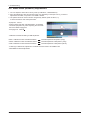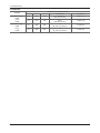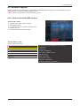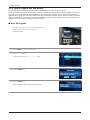
1
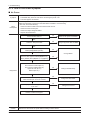
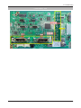
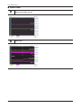
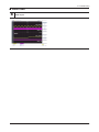
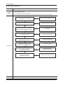
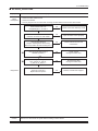
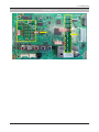
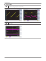
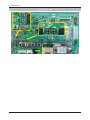
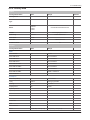
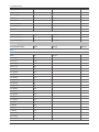
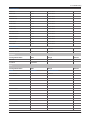
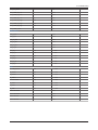
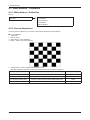
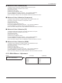
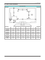
4. Troubleshooting 4. Troubleshooting 4-1. Troubleshooting 4-1-1. Previous check 1. Check the various cable connections first. • Check to see if there is a burnt or damaged cable. • Check to see if there is a disconnected or loose cable connection. • Check to see if the cables are connected according to the connection diagram. 2. Check the power input to the Main Board. 14p cable Power Assy Power Assy LVDS Cable 14p cable Main Assy Main Assy Speaker Speaker Main Assy (CN202 / 204) Power Assy (CMN801) LVDS Cable T-CON Speaker Main Assy (CN201 / 203) Speaker Power Assy (CMN801) 1 B5V 2 SW_PW 1 B5V 2 SW_PW 1 B5V 2 SW_PW 1 B5V 2 3 B5V 4 A5V 3 B5V 4 A5V 3 B5V 4 A5V 3 B5V 4 SW_PW A5V 5 GND 6 GND 5 GND 6 GND 5 GND 6 GND 5 GND 6 GND 7 B12VS 8 GND 7 B12VS 8 GND 7 B12VS 8 GND 7 B12VS 8 GND SW_INV 9 B12VS 10 SW_INV 9 B12VS 10 SW_INV 9 B12VS 10 SW_INV 9 B12VS 10 11 B13V 12 NC 11 B13V 12 NC 11 B13V 12 NC 11 B13V 12 NC 13 B13V 14 DMM 13 B13V 14 DMM 13 B13V 14 DMM 13 B13V 14 DMM 4-1 4. Troubleshooting 4-1-2. How to check fault symptom No Power -- The LEDs on the front panel do not work when connecting the power cord. Symptom -- The SMPS relay does not work when connecting the power cord. -- The units appears to be dead. Major checkpoints The IP relay or the LEDs on the front panel does not work when connecting the power cord if the cables are improperly connected or the Main Board or SMPS is not functioning. In this case, check the following: -- Check the internal cable connection status inside the unit. -- Check the fuses of each part. -- Check the output voltage of SMPS. -- Replace the Main Board. Power indicator LED on? No Check an AC power connection. Yes Check the 14P power cable No Change 14p power cable or SMPS. Yes Check ‘Stand-By 5V’ DC5V appear at BD207(middle)/BD214(small)? No Yes Check ‘Power input of Main Assy’ ? DC B13V, B5V appear at BD209(M)/BD221(S) (B13V), BD208, BD213(M)/BD210, 212(S)(B5V)? Change SMPS. No Yes Diagnostics Check ‘Power of main IC(B1.1V)’ Check ‘Power of DDR IC(B1.9V)’ appear at L201 (B1.1V) BD1012 (B1.9V) ? No Change the Main Assy. Yes Check ‘Power of LVDS (13V)’ appear at LVDS connector Pin #1~5 of T-con b’d? No Change the LVDS cable. Yes Does proper DC B13V appear at F1 of T-con b’d? No Yes Please, Contact tech support. Caution 4-2 Make sure to disconnect the power before working on the IP board. Change the T-con b’d. 4. Troubleshooting Location (Main) - TOP Location (Main) - T-CON 4-3 4. Troubleshooting No video_HDMI1, 2 - Digital signal Symptom Major checkpoints -- Audio is normal but no picture is displayed on the screen. -- Check the HDMI source. -- Check the HDMI switch, Check the Chelsea. -- This may happen when the LVDS cable connecting the Main Board and the Panel is disconnected. Power indicator LED is off. Lamp(Backlight) on, no video ? No Check a set in the 'Stand-by mode'. Yes check the Self Diagnosis (SupportSelf DiagnosisPicture Test) Dose the promblem still exist self diagnosis ? No Check external devices and connections. Yes Check the HDMI source and check the connection of HDMI cable ? No Input the HDMI signal properly. Yes Does the signal appear at CN602 (Pin#12 , #7 )(HDMI1) CN601 (Pin#12 , #7 )(HDMI2) (HDMI RX_Clk , RX_Data) ? No Check CN502, CN503. Check HDMI cable. Change the Main Assy. No Check IC1001 (X5N) Change the Main Assy. Yes Diagnostics Does the digital data appear at TP-E_TXCLK+, E_TXCLK- , O_TXCLK+, O_TXCLK-? Yes Check the LVDS cable ? Check the T-Con B’d ? Replace the LCD panel ? Caution 4-4 No Please, Contact Tech support. Make sure to disconnect the power before working on the IP board. 4. Troubleshooting Location (Main) - TOP 4-5 4. Troubleshooting WAVEFORMS 4-6 HDMI input (RX_Data, RX_Clk) LVDS output 4. Troubleshooting No Video_Tuner - CVBS Symptom Major checkpoints -- Audio is normal but no picture is displayed on the screen. -- Check the Tuner CVBS source. -- Check the Tuner, Check the Chelsea. -- This may happen when the LVDS cable connecting the Main Board and the Panel is disconnected. Power indicator LED is off. Lamp(Backlight) on, no video ? No Check a set in the 'Stand-by mode' Yes Check the RF source and check the connection of RF cable ? No Input the RF source properly. Yes check the Self Diagnosis (SupportSelf DiagnosisPicture Test) Dose the promblem still exist self diagnosis ? No Check external devices and connections. Yes Does the DC B1.8V B3.3V appear at #3, #5 Pin of Tuner ? No Change the Main Assy. No Change the Main Assy. Yes Check the CVBS data at #15 Pin of Tuner ? Yes Diagnostics Does the digital data appear at TP-E_TXCLK+, E_TXCLK- , O_TXCLK+, O_TXCLK- ? No Check IC1001 (X5N). Change the Main Assy. Yes Check the LVDS cable ? Check the T-Con B’d ? Replace the LCD panel ? Caution No Please, Contact Tech support. Make sure to disconnect the power before working on the IP board. 4-7 4. Troubleshooting Location (Main) - TOP 4-8 4. Troubleshooting WAVEFORMS LVDS output 4-9 4. Troubleshooting No Video_Tuner DTV Symptom Major checkpoints -- Audio is normal but no picture is displayed on the screen. -- Check the DTV source. -- Check the Tuner, Check the Chelsea. -- This may happen when the LVDS cable connecting the Main Board and the Panel is disconnected. Power indicator LED is off. Lamp(Backlight) on, no video ? No Check a set in the 'Stand-by mode' Yes Check the connection of RF cable ? No Input the RF source properly. Yes check the Self Diagnosis (SupportSelf DiagnosisPicture Test) Dose the promblem still exist self diagnosis ? No Check external devices and connections. Yes Check the 'signal strength' in Self Diagnosis menu Strength is enough ? No Check the D-TV source. Yes Does the DC B1.8V B3.3V appear at #3, #5 Pin of Tuner ? No Change the Main Assy. No Change the Main Assy. No Check IC1001 (X5) Change the Main Assy. No Please, Contact Tech support. Yes Check the DTV data(DIF+, DIF-) appear at #11, #10 Pin of Tuner ? Diagnostics Yes Does the digital data appear at TP-E_TXCLK+, E_TXCLK- , O_TXCLK+, O_TXCLK- ? Yes Check the LVDS cable ? Check the T-Con B'd ? Replace the LCD panel ? Caution 4-10 Make sure to disconnect the power before working on the IP board. 4. Troubleshooting Location (Main) - TOP 4-11 4. Troubleshooting WAVEFORMS 4-12 LVDS output 4. Troubleshooting No Video_Video CVBS Symptom Major checkpoints -- Audio is normal but no picture is displayed on the screen. -- Check the Video CVBS source -- Check the Chelsea. -- This may happen when the LVDS cable connecting the Main Board and the Panel is disconnected. Power indicator LED is off. Lamp(Backlight) on, no video ? No Check a set in the 'Stand-by mode' Yes Check the video source and check the connection of video cable? No Input the video source properly. Yes check the Self Diagnosis (SupportSelf DiagnosisPicture Test) Dose the promblem still exist self diagnosis ? No Check external devices and connections. Yes Does the CVBS data appear at R809/R814(CVBS1) ? No Check CN503 Change the Main Assy. No Check IC1001 (X5) Change the Main Assy. No Please, Contact Tech support. Yes Does the digital data appear at TP-E_TXCLK+, E_TXCLK- , O_TXCLK+, O_TXCLK- ? Yes Diagnostics Caution Check the LVDS cable ? Check the T-Con B'd ? Replace the LCD panel ? Make sure to disconnect the power before working on the IP board. 4-13 4. Troubleshooting Location (Main) - TOP 4-14 4. Troubleshooting WAVEFORMS CVBS OUT (Grey Bar) LVDS output 4-15 4. Troubleshooting No Video_Component Symptom Major checkpoints -- Audio is normal but no picture is displayed on the screen. -- Check the Component source -- Check the chelsea. -- This may happen when the LVDS cable connecting the Main Board and the Panel is disconnected. Power indicator LED is off. Lamp(Backlight) on, no video ? No Check a set in the 'Stand-by mode'. Yes Check the component source and check the connection of component cables (Y,Pb,Pr) ? No Input the component source properly. Yes check the Self Diagnosis (SupportSelf DiagnosisPicture Test) Dose the promblem still exist self diagnosis ? No Check external devices and connections. Yes Does the data appear at R816/R821(COMP_Y) R817 (COMP_PB) R815(COMP_PR) No Check CN403. Change the Main Assy. No Check IC1001 (X5N). Change the Main Assy. No Please, Contact Tech support. Yes Diagnostics Does the digital data appear at TP-E_TXCLK+, E_TXCLK- , O_TXCLK+, O_TXCLK- ? Yes Check the LVDS cable ? Check the T-Con B'd ? Replace the LCD panel ? Caution 4-16 Make sure to disconnect the power before working on the IP board. 4. Troubleshooting Location (Main) - TOP 4-17 4. Troubleshooting WAVEFORMS Compnent_Y (Gray scale) / Pb / Pr (Color bar) LVDS output 4-18 4. Troubleshooting No Sound Symptom Major checkpoints -- Video is normal but there is no sound.. -- When the speaker connectors are disconnected or damaged. -- When the sound processing part of the Main Board is not functioning. -- Speaker defect.. Check the source and check the connection of sound cable (Comp/PC/DVI to HDMI) ? No Input the sound source properly. Yes check the Self Diagnosis (SupportSelf DiagnosisPicture Test) Dose the promblem still exist self diagnosis ? No Check external devices and connections. Yes Does the sound data appear at R404/R405 (AV1, COMP1) No Check CN403. Change the Main Assy No Change the Main Assy. No Check IC1001 (X5N). Check IC301 (Sound AMP). Change the Main Assy. No Please, Contact Tech support. Yes Does the DC B12V appear at BD301? Yes Diagnostics Does the sound data appear at - L-, L+, R-, R+ ? Yes Replace speaker ? Caution Make sure to disconnect the power before working on the IP board. 4-19 4. Troubleshooting Location (Main) - TOP 4-20 4. Troubleshooting WAVEFORMS Speaker out 4-21 4. Troubleshooting 4-2. Factory Mode Adjustments 4-2-1 Entering Factory Mode • If you do not have Factory remote - control Power OFF MUTE 1 8 2 Power ON • If you do not have Factory remote - control INFO Factory If you don’t have Factory remote control, can’t control some menu. Option Control SVC T-MX5FAUSC(FHD)/T-MX5HAUSC(HD) X7-MW-0013 X5-App-0013 OPTION : XXXXXXXX Expert ADC : HDMI / COMP / PC / AV ADC/WB EDID SUCCESS HDCP : SUCCESS Current Flash : Flash 0 Build Date : XX-XX-XXXX DATE OF PURCHASE : XX/XX/XX 4-22 4. Troubleshooting 4-2-2. Factory Data Option Factory Menu Name Data Factory Reset - Range Remark Type Model UD5003 UD4003 LD503 LD403 TUNER ALPS Audio Amp TAS5715 Front Color NONE Local Set Other Exhibition Mode Off UD5003/UD4003/LD503/LD403 ALPS/Xugang/SECCustom TAS5715/NTP3200 Other/S,America On Control Factory Menu Name Data Range Off On/Off EDID EDID ON/OFF EDID WRITE ALL Success/Failure EDID WRITE PC Success/Failure EDID WRITE DVI Success/Failure EDID WRITE HDMI1 Success/Failure EDID WRITE HDMI2 Success/Failure EDID WRITE HDMI3 Success/Failure EDID WRITE HDMI4 HDMI 1.3/HDMI1/2 EDID VERSION Sub Option Mute Time(VIDEO) 4 0ms~1000ms ready Failure Debug/Login/UART HotPlug On ON/OFF Hotplugcontrol On 0~255 Spread Spectrum On On/Off Period 60K 40K/50K/60K Amplitude 2 0/0.5/1/1.5/2 DDR Spread 2% Off/1%/2% Auto Power On Arab Off NT Conversion Off Mirror ON(Middle) / OFF(Small) Spread Spectrum ON(Middle) / OFF(Small) 4-23 4. Troubleshooting HDMI EQ1 Middle Low/Middle/High/Strong HDMI EQ2 Middle Low/Middle/High/Strong HDMI EQ3 Middle Low/Middle/High/Strong HDMI EQ4 Middle Low/Middle/High/Strong EER Count 2230 WM Calib Panel Enter Key Panel Display Time Checksum XXXX View Log Font Data Viewer Dimm Type EXT EXT/INT Gamma 0.88 0.88/0.90/0.93/0.95/0.98/Off Carrier Mute Off On/Off Anynet+ Off On/Off High Devi Off On/Off Volume Cureve NT NT/EU/EA HotPlug Delay 3 0~63 HP Ident Low High/Low PC Ident On On/Off Watchdog On On/Off LVDS Format JEIDA / VESA(19D4003.32D403) JEIDA / VESA OSD Resolution 1366*768 HPD Polarity Info Live Bus Stop OTA Code OTA Duration Test Alternate Del Ignore VCT Version On On/Off Change OSD Language KOR ENG/KOR VCR Mode Off On/Off Shop Mode OFF ON/OFF Shop Mode OFF ON/OFF PDP Option Hotel Option Shop Option USB DEMO ON(SEC) USB DEMO OFF(SEC) Sound 4-24 4. Troubleshooting BD Mode A2K Prescale 20 0~40 BTSC Mono Prescale 20 0~40 BTSC streo Prescale 20 0~40 SAP Prescale 20 0~40 BTSC M2S Threshold 0x80 0xA0~0x9F BTSC S2M Threshold 0x70 0xA0~0x9F Carrier Mute Thr High 0x39 0x00~0x7F Carrier Mute Thr Low 0x26 0x00~0x7F MP3 Level -6dB -12dB~0dB Master Vol 16 0~255 PWM Modulation 85 0~255 DRC1 Threshold 0x35 0x00~0x7F DRC2 Threshold 0x23 0x00~0x7F SPEAKER EQ On On/Off SC1 Vol 16 0~255 SC2 Vol 16 0~255 Audio Delay 20ms 0~150ms [Edu] SPK Level 1 0~8 [Edu] MIC Level 1 0~8 [Edu] PGA Gain 2dB 0~59dB EQ Check Sum 0xFA9C BTSC Pilot NSR On Thr BTSC Pilot NSR Off Thr BTSC Stereo On Thr BTSC Stereo Off Thr SAP Amp On Thr SAP Amp Off Thr SAP NSR On Thr SAP NSR Off Thr Carrier Mute Amp On Thr Carrier Mute Amp Off Thr Carrier NSR On Thr Carrier NSR Off Thr SUB AMP Master Vol SUB AMP PWM Mod SUB DRC Thresh SUB Speaker EQ Config Option Num of AV 1 0~3 Num of SVIDEO 0 1~3 4-25 4. Troubleshooting Num of Comp 1 1~3 Num of HDMI 2 0~4 Num of SCART 0 DVI Sound 1 0~1 HeadPhone 0 0~1 On On/Off Off Off/1~13 Off Off/1~31 Data Range Mode Off On/Off Color Mode Movie Color Tone Cool Msub Brigh 128 Msub Contr 128 W1_RGAIN 138 W1_BGAIN 104 W1_ROFFS 130 W1_BOFFS 127 W2_RGAIN 131 W2_BGAIN 64 W2_ROFFS 133 W2_BOFFS 129 W3_RGAIN 128 W3_BGAIN 128 W3_ROFFS 128 W3_BOFFS 128 N_RGAIN 131 N_BGAIN 122 N_ROFFS 128 N_BOFFS 129 Movie Countr 100 Movie Brigh 45 Movie Color 55 Num of USB Port LNA SUPPORT MFT Offset Test Pattern Master Test Pattern FBE Test Pattern LOGIC Test Pattern Advanced Factory Menu Name PBE WM Movie 4-26 Remark 4. Troubleshooting Movie Sharp 55 Movie Tint 50 Movie BkLight 10 M.Gamma Off M_Sub Gamma 0 EPA Standard Std Contr 100 0~100 Std Bright 45 0~100 Std Sharp 50 0~100 Std Color 50 0~100 Std Tint 50 0~100 Std Backight 8 0~10 RF dB1 Level 4 0~255 RF dB2 Level 6 0~255 RF dB3 Level 10 0~255 RF dB4 Level 20 0~255 Power Key Protect Off On/Off UART Select Auto Wall Auto Wall/Debug/MDC/On1/On2 Debug Mode Debug Off Debug Off/Debug Smart/Debug RunTime ADJUST Dynamic Dimming LNA Plus LNA Plus Back End Mute PDP FRC VisualTEST Plus Disable Standby Mode Time 45 Min Delete alt.ver 2 Flash OTA confirm Time 90 Min 3 Min/90 Min OTA limit Time 3 Hour 3 Min/3Hour Dynamic CE Off On/Off FWC Off On/Off 1080p 48Hz On On/Off PWM Max 100 1~100 DTV LNA Auto On/Off HDCP Download Off On/Off USB Download Off On/Off PAL BG 1 0~3 PAL DK 1 0~3 2 Min/45 Min Quick Start YC_Delay 4-27 4. Troubleshooting PAL I 1 0~3 SECAM BG 4 0~3 SECAM DK 4 0~3 SECAML 4 0~3 NTSC 358 1 0~3 NTSC 443 0 0~3 AV PAL 1 0~3 AV SECAM 4 0~3 AV NT358 1 0~3 AV NT443 1 0~3 AV PAL60 1 0~3 H1 GAIN 0X12 0X00~0XFF H2 GAIN 0X08 0X00~0XFF H3 GAIN 0X08 0X00~0XFF H4 GAIN 0X08 0X00~0XFF V1 GAIN 0X10 0X00~0XFF V2 GAIN 0X0E 0X00~0XFF H OVERSHOOT 0X20 0X00~0XFF V OVERSHOOT 0X20 0X00~0XFF H UNDERSHOOT 0X20 0X00~0XFF V UNDERSHOOT 0X20 0X00~0XFF CORING TH2 0X01 0X01~0X0F CORING TH1 0X01 0X01~0X0F SKIN_X 0X00 0X00~0XFF SKIN_Y 0X01 0X00~0XFF B_SLOPE 0X8A 0X00~0XFF DLC_ML 0X90 0X00~0XFF DLC_MH 0X90 0X00~0XFF DLC_H 0XEB 0X00~0XFF SKIN_SAT 0X00 0X00~0XFF SKIN_HUE 0X20 0X00~0XFF M_SKIN_HUE 0X40 0X00~0XFF M_SKIN_X 0X00 0X00~0XFF M_SKIN_Y 0X00 0X01~0X0F MID_COLOR_LEVEL 0XB8 0X01~0X0F M_MID_COLOR_LEVE 0X95 0X01~0X0F 7.5 IRE NTSC OFF ON/OFF 7.5 IRE OFFSET 16 0~60 SHARPNESS PE PQ OTHERS 4-28 4. Troubleshooting COLOR SPACE RED SAT 0X12 0X00~0XFF RED HUE 0X40 0X00~0XFF GREEN SAT 0X16 0X00~0XFF GREEN HUE 0X70 0X00~0XFF BLUE SAT 0X1A 0X00~0XFF BLUE HUE 0X70 0X00~0XFF CYAN SAT 0X16 0X00~0XFF CYAN HUE 0X40 0X00~0XFF MAGENTA SAT 0X16 0X00~0XFF MAGENTA HUE 0X40 0X00~0XFF YELLOW SAT 0X0F 0X00~0XFF YELLOW HUE 0X70 0X00~0XFF FWC BLUE 0X0F 0X00~0XFF FWC RED 0X0F 0X00~0XFF EEPROM RESET OFF ON/OFF NVR ALL CLEAR OFF ON/OFF Factory Menu Name Data Range N/D ADJ OFF ON/OFF SOURCE CURRENT EEPROM RESET EXPERT Remark SVC Factory Menu Name Data Range MODE DYNAMIC DYNAMIC/MOVIE SCC ON/OFF OFF ON/OFF HX 272 0~1024 HY 278 0~1024 LX 272 0~1024 LY 278 0~1024 SSCC HX 554 0~1024 SSCC HY 573 0~1024 SSCC LX 550 0~1024 SSCC LY 576 0~1024 PSCC CONST … PSCC HX 554 0~1024 PSCC HY 573 0~1024 PSCC LX 550 0~1024 Remark SCC INPUT DATA SSCC CONST 4-29 4. Troubleshooting PSCC LY 576 0~1024 SCC SOURCE DATA PBA PBA/PANEL SWAP PBA PBA/PANEL 1st_AV_Low 64 0 ~ 1020 1st_AV_High 880 0 ~ 1020 1st_AV_Delta 2 0~7 1st_COMP_Y_Low 64 0 ~ 1020 1st_COMP_Cb_Low … 1st_COMP_Cr_Low … 1st_COMP_Y_High 940 1st_COMP_Cb_High … 1st_COMP_Cr_High … 1st_COMP_Delta 2 0~7 1st_PC_R_Low 16 0 ~ 1020 1st_PC_G_Low … 1st_PC_B_Low … 1st_PC_R_High 1004 1st_PC_G_Low … 1st_PC_B_Low … 1st_PC_Delta 2 0~7 2nd_AV_R_Low 4 fixed 2nd_AV_G_Low 4 fixed 2nd_AV_B_Low 4 fixed 2nd_AV_R_High 940 fixed 2nd_AV_G_High 940 fixed 2nd_AV_B_High 940 fixed 2nd_AV_Delta 2 0~7 2nd_COMP_R_Low 4 fixed 2nd_COMP_G_Low 4 fixed 2nd_COMP_B_Low 4 fixed 2nd_COMP_R_High 940 fixed 2nd_COMP_G_High 940 fixed 2nd_COMP_B_High 940 fixed 2nd_COMP_Delta 2 0~7 2nd_PC_R_Low 4 fixed 2nd_PC_G_Low 4 fixed 2nd_PC_B_Low 4 fixed 2nd_PC_R_High 940 fixed 2nd_PC_G_High 940 fixed 2nd_PC_B_High 940 fixed PANEL AUTO SETTING 4-30 0 ~ 1020 0 ~ 1020 4. Troubleshooting 2nd_PC_Delta 2 0~7 2nd_HDMI_R_Low 4 fixed 2nd_HDMI_G_Low 4 fixed 2nd_HDMI_B_Low 4 fixed 2nd_HDMI_R_High 940 fixed 2nd_HDMI_G_High 940 fixed 2nd_HDMI_B_High 940 fixed 2nd_HDMI_Delta 2 0~7 1st_Y_GH 0 fixed 1st_Y_GL 0 fixed 1st_Cb_BH 0 fixed 1st_Cb_BL 0 fixed 1st_Cr_RH 0 fixed 1st_Cr_RL 0 fixed 2nd_R_L 134 0 ~ 255 2nd_G_L 134 0 ~ 255 2nd_B_L 134 0 ~ 255 2nd_R_H 49 0 ~ 255 2nd_G_H 49 0 ~ 255 2nd_B_H 49 0 ~ 255 Sub Brightness 128 0 ~ 1023 R_Offset 512 0 ~ 1023 G_Offset 512 0 ~ 1023 B_Offset 512 0 ~ 1023 Sub Contrast 128 0 ~ 1023 R_Gain 512 0 ~ 1023 G_Gain 512 0 ~ 1023 B_Gain 512 0 ~ 1023 Movie R Offset … fixed Movie B Offset … fixed Movie R Gain … fixed Movie B Gain … fixed ADC Result WB 4-31 4. Troubleshooting 4-3. White Balance - Calibration 4-3-1. White Balance -Calibration Factory ADC / WB AV Calibration Comp Calibration PC Calibration HDMI Calibration 4-3-2. Service Adjustment You must perform Calibration in the Lattice Pattern before adjusting the White Balance. Color Calibration Adjust spec. 1. Source : HDMI 2. Setting Mode : 1280*720@60Hz 3. Pattern : Pattern #24 (Chess Pattern) 4. Use Equipment : CA210 & Master MSPG925 Generator Use other equipment only after comparing The result with that of The Master equipment. Input mode Calibration Pattern CVBS IN (Model_#1) Perform in NTSC B&W Pattern #24 Lattice Component IN (Model_#6) Perform in 720p B&W Pattern #24 Lattice PC Analog IN (Model_#21) Perform in VESA XGA (1024x768) B&W Pattern #24 Lattice HDMI IN Perform in 720p B&W Pattern #24 Lattice 4-32 4. Troubleshooting Method of Color Calibration (AV) 1) Apply the NTSC Lattice (N0. 3) pattern signal to the AV IN 1 port. 2) Press the Source key to switch to “AV1” mode. 3) Enter Service mode. 4) Select the “ADC” menu. 5) Select the “AV Calibration” menu. 6) In “AV Calibration Off” status, press the “ ” key to perform Calibration. 7) When Calibration is complete, it returns to the high-level menu. 8) You can see the change of the “AV Calibration” status from Failure to Success. Method of Color Calibration (Component) 1) Apply the 720p Lattice (N0. 6) pattern signal to the Component IN 1 port. 2) Press the Source key to switch to “Component1” mode. 3) Enter Service mode. 4) Select the “ADC” menu. 5) Select the “Comp Calibration” menu. 6) In “Comp Calibration Off” status, press the “ ” key to perform Calibration. 7) When Calibration is complete, it returns to the high-level menu. 8) You can see the change of the “Comp Calibration” status from Failure to Success. Method of Color Calibration (PC) 1) Apply the VESA XGA Lattice (N0. 21) pattern signal to the PC IN port. 2) Press the Source key to switch to “PC” mode. 3) Enter Service mode. 4) Select the “ADC” menu. 5) Select the “PC Calibration” menu. 6) In “PC Calibration Off” status, press the “ ” key to perform Calibration. 7) When Calibration is complete, it returns to the high-level menu. 8) You can see the change of the “PC Calibration” status from Failure to Success. Method of Color Calibration (HDMI) 1) Apply the 720p Lattice (N0. 6) pattern signal to the HDMI1/DVI IN port. 2) Press the Source key to switch to “HDMI1” mode. 3) Enter Service mode. 4) Select the “ADC” menu. 5) Select the “HDMI Calibration” menu. 6) In “HDMI Calibration Off” status, press the “ ” key to perform Calibration. 7) When Calibration is complete, it returns to the high-level menu. 8) You can see the change of the “HDMI Calibration” status from Failure to Success. 4-3-3. White Balance - Adjustment Factory ADC / WB - White Balance (Low light) (High light) Sub Bright Sub Contrast R offset R gain G offset G gain B offset B gain 4-33 4. Troubleshooting 4-4. White Ratio (Balance) Adjustment 1. You can adjust the white ratio in factory mode (1:Calibration, 3:White-Balance). 2. Since the adjustment value and the data value vary depending on the input source, you have to adjust these in CVBS, Component 1 and HDMI 1 modes. 3. The optimal values for each mode are configured by default. (Refer to Table 1, 2) It varies with Panel’s size and Specification. - Equipment : CS-210 - Pattern: MIK K-7256 #92 “Flat W/B Pattern" as standard - Use other equipment only after comparing the result with that of the Master equipment. - Set Aging time : 60min - Calibration and Manual setting for WB adjustment. HDMI : Calibration at #24 Chessboard Pattern Manual adjustment #92 pattern (720p) COMP: Calibration at #24 Chessboard Pattern Manual adjustment at #92 pattern (720p) CVBS: Calibration at #24 Chessboard Pattern Manual adjustment at #92 pattern (NTSC) - If finishing in HDMI mode, adjustment coordinate is almost same in AV/COMP mode. - White Balance Manual Adjustment 4-34 4. Troubleshooting UN19D4003BD Adjustment Coordinate CA-210 P-Mode [Dynamic Cool1] HDMI Comp CVBS [Movie Warm2] HDMI Comp CVBS x y Y(Luminance) T(K)+MPCD 10,000 (+/- 0) H/L 281 288 R-Gain : 132 B-Gain : 154 Sub_CT : 128 L/L - - (Sub_Brt:128 Fix) R-Offset, B-Offset : 128 - H/L - - (M-Sub_CT:128 Fix) appiled Movie W2 R/B-gain - L/L - - (M-Sub_Brt:128 Fix) appiled Movie W2 R/B-gain - x y Y(Luminance) T(K)+MPCD H/L 264 274 30.1 fL (Sub_CT:133 Fix) 12,000 (±0) L/L - - 1.8 fL (Sub-Brt:128 Fix) - H/L 319 340 - fL (M_Sub_CT:128 Fix) 6,500(+-0) L/L - - - fL (M_Sub_CT:128 Fix) - UN26D4003BD Adjustment Coordinate CA-210 P-Mode [Dynamic Cool1] HDMI Comp CVBS [Movie Warm2] HDMI Comp CVBS UN32D4003BD Adjustment Coordinate CA-210 P-Mode [Dynamic Cool1] HDMI Comp CVBS [Movie Warm2] HDMI Comp CVBS x y Y(Luminance) T(K)+MPCD 12,000 (±0) H/L 264 274 31.8 fL (Sub_CT:136 Fix) L/L - - 1.8 fL (Sub-Brt:128 Fix) - H/L 319 340 - fL (M_Sub_CT:128 Fix) 6,500(+-0) L/L - - - fL (M_Sub_CT:128 Fix) - x y Y(Luminance) T(K)+MPCD H/L 264 274 31.8 fL (Sub_CT:136 Fix) 12,000 (±0) L/L - - 1.8 fL (Sub-Brt:128 Fix) - H/L 319 340 - fL (M_Sub_CT:128 Fix) 6,500(+-0) L/L - - - fL (M_Sub_CT:128 Fix) - UN22D5003BF Adjustment Coordinate CA-210 P-Mode [Dynamic Cool1] HDMI Comp CVBS [Movie Warm2] HDMI Comp CVBS 4-35 4. Troubleshooting LN32D40*E*D Adjustment Coordinate CA-210 P-Mode [Dynamic Cool1] HDMI Comp CVBS [Movie Warm2] HDMI Comp CVBS 4-36 x y Y(Luminance) T(K)+MPCD 12,000 (±0) H/L 272 278 38.0 fL (Sub_CT:134 Fix) L/L 272 278 2.2 fL (Sub-Brt:128 Fix) 12,000 (±0) H/L 306 327 - fL (M_Sub_CT:128 Fix) 6,500 (±0) L/L 306 327 - fL (M_Sub_CT:128 Fix) 6,500 (±0) 4. Troubleshooting 4-5. Software Upgrade Software Upgrade can be performed by downloading the latest firmware from samsung.com to a USB memory device. Current Version - the software already installed in the TV. Note : Software is represented as ‘Year/Month/Day_Version’. 4-5-1. How to check the SW version Use the main menu 1. Click the “menu” key in remote controler. 2. Select Support menu. 3. Locate the menu cursor “Software Upgrade” menu. 4. Click the “info” key. 5. Check the Main SW and Micom version. Use the factory mode Access the factory mode Option Control SVC T-MX5FAUSC(FHD)/T-MX5HAUSC(HD) : SW Ver, X7-MW-0013 X5-App-0013 OPTION : XXXXXXXX Expert ADC : HDMI / COMP / PC / AV ADC/WB EDID SUCCESS Advanced HDCP : SUCCESS Current Flash : Flash 0 Build Date : XX-XX-XXXX DATE OF PURCHASE : XX/XX/XX 4-37 4. Troubleshooting 4-5-2. How to Upgade SW and Micom Insert a USB drive containing the firmware upgrade downloaded from samsung.com into the TV. Please be careful to not disconnect the power or remove the USB drive while upgrades are being applied. The TV will turn off and turn on automatically after completing the firmware upgrade. Please check the firmware version after the upgrades are complete (the new version will have a higher number than the older version). When software is upgraded, video and audio settings you have When software is upgraded, video and audio settings you have you write down your settings so that you can easily reset them after the upgrade. Main SW upgrade 1. Store the sw program named "T-MX5FAUSC"(FHD) or "T-MX5HAUSC"(HD) in USB memory stick. -- Connect the USB. 2. Click the MENU key in remote controler. 3. Select Support menu. -- Locate the menu cursor Software Upgrade menu. 4. Click the ENTER key. 5. Click the ENTER key. -- Wait for upgrade complete and check the SW version. 4-38 4. Troubleshooting 4-6. Rear Cover Dimension Cover-Rear Area 1 2 3 4 5 6 19D4003 121.8 203.5 51.8 67.5 75.0 75.0 26D4003 166.0 68.0 82.7 378.0 200.0 200.0 32D4003 183.4 80.3 142.1 496.4 200.0 200.0 22D5003 157.6 268.8 53.8 68.8 75.0 75.0 40D5003 236.3 159.4 196.6 604.7 200.0 200.0 32D40* 235.8 50.7 125 542.7 200 200 4-39