1
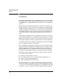
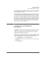
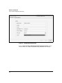
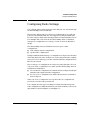
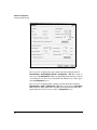
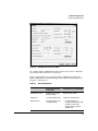
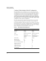
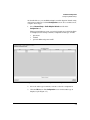
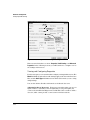
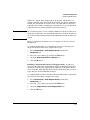
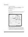
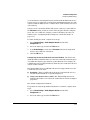
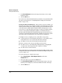
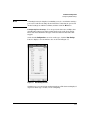
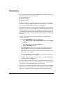
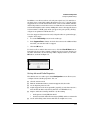
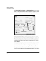
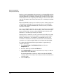
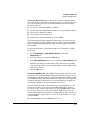
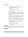
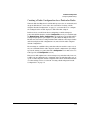
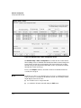
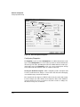
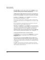
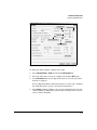
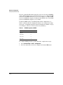
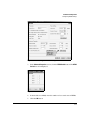
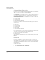
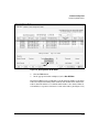
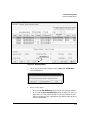
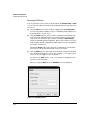
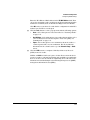
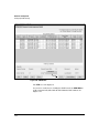
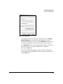
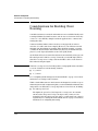
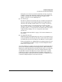
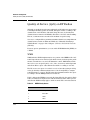
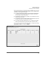
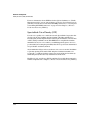
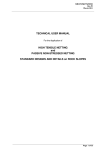
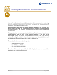
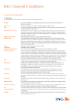
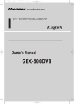
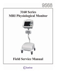
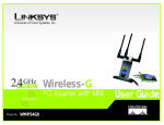
3
Radio Port Configuration
Contents
Overview . . . . . . . . . . . . . . . . . . . . . . . . . . . . . . . . . . . . . . . . . . . . . . . . . . . . . . 3-2
Country-Code and Regulatory Procedures . . . . . . . . . . . . . . . . . . . . . . . . . . 3-3
Configuring Radio Settings . . . . . . . . . . . . . . . . . . . . . . . . . . . . . . . . . . . . . . . 3-5
Creating a Radio Adoption Default Configuration . . . . . . . . . . . . . . . . 3-8
Viewing and Configuring Properties . . . . . . . . . . . . . . . . . . . . . . . 3-10
Configuring Radio Settings . . . . . . . . . . . . . . . . . . . . . . . . . . . . . . . 3-12
Setting Advanced Radio Properties . . . . . . . . . . . . . . . . . . . . . . . . 3-17
Creating a Radio Configuration for a Particular Radio . . . . . . . . . . . 3-25
Configuring Properties . . . . . . . . . . . . . . . . . . . . . . . . . . . . . . . . . . 3-28
Configuring Radio Settings for a Particular Radio . . . . . . . . . . . 3-30
Configuring Advanced Properties for a Particular Radio . . . . . . 3-32
Configuring Multiple Radios at Once . . . . . . . . . . . . . . . . . . . . . . 3-36
Running ACS . . . . . . . . . . . . . . . . . . . . . . . . . . . . . . . . . . . . . . . . . . . 3-36
Resetting a Radio . . . . . . . . . . . . . . . . . . . . . . . . . . . . . . . . . . . . . . . 3-38
Managing RP Radios . . . . . . . . . . . . . . . . . . . . . . . . . . . . . . . . . . . . 3-40
Considerations for Enabling Client Roaming . . . . . . . . . . . . . . . . . . . . . . . 3-44
Quality of Service (QoS) on RP Radios . . . . . . . . . . . . . . . . . . . . . . . . . . . . 3-46
WMM . . . . . . . . . . . . . . . . . . . . . . . . . . . . . . . . . . . . . . . . . . . . . . . . . . . . . 3-46
SpectraLink Voice Priority (SVP) . . . . . . . . . . . . . . . . . . . . . . . . . . . . . 3-48
3-1
Radio Port Configuration
Overview
Overview
The ProCurve Wireless Edge Services xl Module manages the ProCurve Radio
Ports (RPs) 210, 220, and 230. Using their Ethernet port and one or two radios,
these IEEE 802.11-compliant RPs grant wireless stations access to an Ethernet
network.
RPs provide the radio signal and the physical connection to wireless users,
but little intelligence on their own. Instead of configuring each RP individually
through its own management interface, you manage them all centrally with
the Wireless Edge Services xl Module. The advantage of this design is that the
entire Wireless LAN System (the module together with its adopted RPs) is
controlled together for consistent and transparent network access for all
users.
In this chapter, you will learn how to configure Procurve RPs 210, 220, and 230
using the Wireless Edge Services xl Module’s Web browser interface. You will
first learn about the radio country codes, which ensure that radios operate at
the frequencies and power levels specified by various countries’ regulations.
You will then learn about creating radio configurations for the Wireless Edge
Services xl Module to deploy to adopted RPs.
These configurations include basic settings such as a radio’s channel, power,
and rate sets. When configuring these settings, you must consider the method
that radios should use to select their channel and the level at which to set
radios’ maximum power. You will also learn how to specify basic and supported data rates depending on the types of stations that a radio must support.
This chapter will also discuss setting advanced radio properties, which may
be necessary when you want to:
■
install an external antenna on a radio
■
use a radio to support Voice-over-wireless LAN (VoWLAN) devices
■
improve a radio’s data throughput rate
■
enable self healing functions on a radio
The ProCurve RPs 210, 220, and 230 support client roaming, which allows a
mobile wireless station to maintain connectivity while moving from one radio
coverage area to another. This chapter will give you a few guidelines for setting
up wireless coverage to facilitate seamless roaming. More detailed instruc-
3-2
Radio Port Configuration
Country-Code and Regulatory Procedures
tions on enabling the best possible roaming between RPs adopted by multiple
Wireless Edge Services xl Modules can be found in Chapter 9: Fast Layer 2
Roaming and Layer 3 Mobility.
In addition, the ProCurve RPs improve quality of service (QoS) in the wireless
network with support for Wi-Fi Multimedia (WMM). Each radio can divide
outbound wireless traffic into four queues based on priority value or on WLAN.
For example, voice traffic (if appropriately marked) is placed in the highestpriority queue. The default settings for each queue are designed to provide a
high QoS for voice and video traffic from RPs to associated stations. The RPs’
QoS capabilities are discussed with the capabilities of the Wireless LAN
System as a whole in “Traffic Management (QoS)” on page 4-90 of Chapter 4:
Wireless Local Area Networks (WLANs).
Country-Code and Regulatory
Procedures
While IEEE has codified the international wireless network specifications and
standards, each country has its own regulations for legal frequencies and
wireless use requirements. It is important to be aware of your country’s
standards when configuring your network.
Setting a device’s country code configures it to use radio settings that are legal
in that country. You must set the country code on your ProCurve Wireless Edge
Services xl Module before it will adopt RPs. Complete these steps:
1.
Select Network Setup and click the Configuration tab.
2.
In the Country field, use the drop-down menu to select your country. (See
Figure 3-1.)
3.
Click the Apply button.
3-3
Radio Port Configuration
Country-Code and Regulatory Procedures
Figure 3-1. Configuring the Country Code
Refer to http://www.hp.com/rnd/support/manuals/rports.htm for information about each country’s regulations and permissible radio settings.
3-4
Radio Port Configuration
Configuring Radio Settings
Configuring Radio Settings
You configure radio settings for the ProCurve RPs 210, 220, and 230 through
the Wireless Edge Services xl Module.
The ProCurve RP 220 and 230 each have two built-in radios; one radio supports 802.11a standards while the other supports 802.11bg standards. The
ProCurve 210 has a single radio that supports the 802.11bg standards. You can
have multiple RPs on the network; the Wireless Edge Services xl Module
manages the configurations for each type of radio on all of the RPs that it
adopts.
The Wireless Edge Services xl Module stores two types of radio
configurations:
■
radio adoption default configurations
■
specific radio configurations
Settings established in the first type of configuration are deployed to all radios
when first adopted. In other words, the two radio adoption default configurations (one for each radio type) are like customized default configurations for
RPs in your network.
The second type of configurations are targeted to particular radios. You can
only create such a configuration for a radio after the Wireless Edge Services
xl Module has identified it:
■
You can alter the configuration of a radio that has been adopted and begun
using the radio adoption default configuration.
■
You can create a configuration for an RP radio that has been identified
but not adopted.
When you create a configuration for a specific radio, the configuration is
preserved even if the radio powers down.
You configure the same types of settings for adoption default and specific
radio configurations, and the Web browser screens from which you do so look
quite similar, as shown in Figure 3-2 and Figure 3-3.
3-5
Radio Port Configuration
Configuring Radio Settings
Figure 3-2. Default Configuration Screen for a Radio Type
The screen for configuring the radio adoption default settings is labeled
Network Setup > Radio Adoption Defaults > Configuration > Edit. The top left on
the screen reads Configuration, and the top right displays the radio type: 802.11a
or 802.11bg. For ease of reference, this guide will call that screen a radio type’s
default Configuration screen.
The screen for configuring radio settings on a particular radio is labeled
Network Setup > Radio > Configuration > Edit. The top left also reads Configuration, but the top right displays the description for that particular radio. The
guide will refer to that screen as a radio’s Configuration screen.
3-6
Radio Port Configuration
Configuring Radio Settings
Figure 3-3. Configuration Screen for a Radio
Be careful to make configuration changes on the correct screen. Otherwise,
the changes will not take effect as expected.
Table 3-1 summarizes how you edit the radio configurations and how the
Wireless Edge Services xl Module deploys them. For more information, see
Chapter 1: Introduction.
Table 3-1.
Radio Configurations
Radio Adoption Default
Configuration
Configuration for a Targeted Radio
Configuration screen
Network Setup > Radio
Adoption Defaults
Network Setup > Radio
Deployed to
any newly adopted radio
a particular, identified radio
Deployed when
the module adopts a new,
unconfigured radio
• the module adopts the
unadopted, but identified, radio
• you apply changes to the
configuration of an already
adopted radio
3-7
Radio Port Configuration
Configuring Radio Settings
Creating a Radio Adoption Default Configuration
The Wireless Edge Services xl Module stores two radio adoption default
configurations, one for 802.11a radios and one for 802.11bg radios. It deploys
the configurations to radios on any unconfigured RP that it adopts. These
configurations only affect newly adopted radios. Therefore, configuration
changes do not take effect unless a new RP is adopted, and they only take
effect on that new RP; RP radios adopted before the changes continue using
the settings that they received either from the former radio adoption default
configuration or from a targeted configuration.
The radio adoption default configurations included in the factory default
settings for the Wireless Edge Services xl Module are shown in Table 3-2.
You should establish the settings best suited for most radios in your environment. Best practice is to alter these configurations before you install the RPs.
You can then alter a particular radio’s settings as necessary. (See “Creating a
Radio Configuration for a Particular Radio” on page 3-25.)
Table 3-2.
3-8
Radio Adoption Default Configurations
Setting
802.11a
802.11bg
Placement
Indoors
Indoors
Channel
Random
Random
Power
Depends on country code
Depends on country code
Rate settings
Basic: 6, 12, 24
Supported: 6, 9, 12, 18, 24,
36, 48, 54
Basic: 1, 2, 5.5, 11
Supported: 1, 2, 5.5, 6, 9, 11,
12, 18, 24, 36, 48, 54
Antenna mode
Diversity
Diversity
Maximum stations
64
64
RTS threshold (bytes)
2346
2346
Beacon interval (microseconds)
100
100
Adoption preference ID
1
1
DTIM period (beacons)
2
2
Support short preamble
—
No
Self healing offset
0
0
Radio Port Configuration
Configuring Radio Settings
As described above, you establish settings for a radio adoption default configuration from a radio type’s default Configuration screen. To access this screen,
complete these steps:
1.
Select Network Setup > Radio Adoption Defaults and click the
Configuration tab.
This screen includes two rows, one for 802.11a and one for 802.11bg. Each
row displays basic settings currently configured for that type of radio:
•
placement
•
channel
•
power in dBm and power in mW
Figure 3-4. Accessing the Radio Adoption Default Configurations
2.
Select the radio type for which you want to alter the configuration.
3.
Click the Edit button. The Configuration screen for that radio type is
displayed. (See Figure 3-5.)
3-9
Radio Port Configuration
Configuring Radio Settings
Model
Radio Type
Background AP
detection
Dedicated to
detecting
rogue APs
Figure 3-5. Radio Adoption Default Configuration Properties
This screen includes three sections: Properties, Radio Settings, and Advanced
Properties. In the following sections, you will learn how to configure each of
the settings on this screen.
Viewing and Configuring Properties
For the most part, you view, rather than configure, settings in this section. The
Model field indicates that these radio settings apply to the 200 series ProCurve
RPs, and the Radio Type field indicates for which 802.11 mode you are configuring settings.
You can also define all radios of this mode as dedicated detectors.
Adopting Radios as Detectors. To increase network security, you can configure a radio to constantly scan for neighboring access points (APs) not
connected to this Wireless Edge Services xl Module. Such a radio is called a
detector, and it cannot provide a connection for wireless stations.
3-10
Radio Port Configuration
Configuring Radio Settings
When you configure this setting as part of the default configuration, you
dedicate all radios of that 802.11 mode. For example, if your network does not
include any stations that use 802.11a mode, you could dedicate all 802.11a
radios in your network to scanning for rogue APs. (Note, however, that these
radios will only detect APs operating in an 802.11a channel.)
Note
As a security measure, you can configure all RPs to be adopted as detectors.
In this way, no RP radio can send wireless traffic into your network until you
access the settings for that particular radio and disable the dedicated detector
option.
For more information on AP detection, see Chapter 13: Wireless Network
Management.
To configure all RP radios of a particular type (802.11a or 802.11bg) to be
adopted as dedicated detectors, complete these steps:
1.
Select Network Setup > Radio Adoption Defaults and click the
Configuration tab.
2.
Select the correct radio type and click the Edit button.
3.
Check the Dedicate this Radio as a Detector box.
4.
Click the OK button.
Enabling a Single-Channel Scan for Unapproved APs. A dedicated
detector radio sends probes for unapproved APs on all allowed channels in
its frequency, but does not support wireless stations. To allow RP radios to
detect some APs, while still supporting stations, enable the radios to scan for
rogue APs only on their individual channels.
To configure single-channel scanning on all adopted RP radios of a particular
type (802.11a or 802.11bg), complete these steps:
1.
Select Network Setup > Radio Adoption Defaults and click the
Configuration tab.
2.
Select the correct radio type and click the Edit button.
3.
Check the Single-channel scan for Unapproved APs box.
4.
Click the OK button.
3-11
Radio Port Configuration
Configuring Radio Settings
Configuring Radio Settings
Configure the basic radio settings in the default Configuration screen’s Radio
Settings section, as shown in Figure 3-6. These settings include:
■
radio placement
■
channel selection method
■
transmit power
■
rate settings
You should configure the settings in this order; the radio placement setting
dictates available channel options, and the channel selection method affects
available power levels.
Placement
Channel Selection
Power Options
Rate Settings
Figure 3-6. Radio Adoption Default Configuration Radio Settings
Defining the Radio Placement. You can configure a radio for indoor use
or for outdoor use. Because a radio adjusts its power and channel settings
according to its placement, it is important to configure this setting accurately.
Not doing so can create various problems, and can even cause you to break
the law. For example, an outdoor RP may need to transmit at higher power to
3-12
Radio Port Configuration
Configuring Radio Settings
overcome distance-based signal loss, but an indoor RP should broadcast at a
lower power to accommodate closer stations and minimize interference with
other local RPs. In addition, some countries allow certain channels to be used
only outdoors.
Unless you are certain that all RPs will operate outdoors, you should leave
the Placement setting at Indoors for the radio adoption default configurations. You can override the setting for outdoor RP radios after they are
installed. (See “Configuring Radio Settings for a Particular Radio” on
page 3-30.)
To define the RP placement, complete these steps:
1.
Select Network Setup > Radio Adoption Defaults and click the
Configuration tab.
2.
Select the radio type and click the Edit button.
3.
In the Radio Settings section, in the Placement field, use the drop-down
menu to select Indoors or Outdoors.
4.
Click the OK button.
Configuring the Desired Channel Selection Method. The 802.11 standards allow RPs to transmit and receive data on several radio channel frequencies within the frequency specified for a particular mode. For example, the
2.4 GHz range (for 802.11bg) includes 14 channels, some of which are allowed
only in certain countries.
The Wireless Edge Services xl Module allows newly adopted radios to select
a channel in one of two ways:
■
Randomly—When each RP radio is adopted, it automatically selects a
random channel within the acceptable frequencies.
■
Using auto channel select (ACS)—The Wireless Edge Services xl
Module helps radios to select the best channel based on noise and signal
properties.
The default configuration is Random.
To specify how newly adopted radios should select a channel, complete these
steps:
1.
Select Network Setup > Radio Adoption Defaults and click the
Configuration tab.
2.
Select the radio type and click the Edit button.
3-13
Radio Port Configuration
Configuring Radio Settings
3.
In the Desired Channel field, use the drop-down menu to select either
Random or ACS.
4.
Click the OK button.
If you want to set channels manually, then you must do so for particular radios
after they are adopted. (See “Configuring Radio Settings for a Particular
Radio” on page 3-30).
Setting the Desired Radio Power. After you have selected a channel, you
must select the radio power. Available settings are determined by previously
defined channel and location settings. A radio’s power determines the broadcast radio frequency (RF) signal strength in dBm. It is important to set the
power level to a value that is strong enough to clearly reach all the stations,
but not so strong that the RF signal is garbled, overwhelms stations, or
interferes with other RPs. The maximum broadcast power may also be governed by local and national restrictions. The optimal power level for a particular channel is best determined by a site survey prior to installation.
You might need to set a higher power to ensure RF coverage when:
■
a radio experiences electromagnetic interference—for example, from a
nearby microwave oven or from other wireless technology
■
the distance between the RP and wireless stations is long
Likewise, you may need to decrease the RF power level when:
■
the radio is close to other RP radios (unintentionally overlapping RF
coverage may cause lost packets and complicate roaming)
■
the radio uses an external antenna
The default radio power setting for 802.11bg radios is 20 dBm, and the default
setting for 802.11a radios is 20 dBm. However, this default might change based
on your country code.
To set the radio power, complete these steps:
3-14
1.
Select Network Setup > Radio Adoption Defaults and click the
Configuration tab.
2.
Select the radio type and click the Edit button.
3.
In the Desired Power (dBm) field, use the drop-down menu to select the
default power setting that you have determined for radios of this type.
4.
Click the OK button.
Radio Port Configuration
Configuring Radio Settings
Note
A warning box may be displayed, reminding you to be careful when setting a
power for a radio that is using external antennas. Verify that the power and
channel settings are within local limits, and then click the OK button.
Configuring Rate Settings. You can specify the data rates, in Mbps, that
default radios support for traffic passing between the radio and a station.
These data rates determine the types of wireless stations that radios will
support.
On the default Configuration screen for a radio type, click the Rate Settings
button to display a screen similar to the one shown in Figure 3-7.
Figure 3-7. Rate Settings Screen
On this screen, you can set basic and supported rates. The data rates displayed
depend on which type of radio you are configuring.
3-15
Radio Port Configuration
Configuring Radio Settings
The basic rates are rates for which RP radios advertise support. A radio uses
and allows stations to use basic rates for:
■
management frames
■
broadcast frames
■
multicast frames
Such frames are sent to all stations associated to a basic service set (BSS);
therefore, if an RP is to support 802.11b stations, it must use only the rates
(1, 2, 5.5, and 11 Mbps) supported by those slower stations.
If an 802.11bg radio does not need to support 802.11b stations, you can set the
basic rates to g only rates (for example, 6, 12 and 24). The higher data rates
for management and broadcast traffic can improve performance in the wireless network. They also prevent the 802.11b stations from associating to the
RP radio and slowing the network. Such a setting is sometimes called 802.11g
only mode.
To select basic data rates for newly adopted radios of a particular type,
complete these steps:
1.
2.
Access the Rate Settings screen for the radio type:
a.
Select Network Setup > Radio Adoption Defaults and click the Configuration tab.
b.
Select the radio type and click the Edit button.
c.
Click the Rate Settings button.
In the Basic Rates column, check the boxes next to the data rates that
radios should use for management, broadcast, and multicast traffic.
By default, the station supports both 802.11b and 802.11g stations with
basic rates 1, 2, 5.5, and 11.
To configure Wi-Fi g-only or pure-g mode on an 802.11bg radio, deselect
1, 2, 5.5, and 11 and select 6, 12, and 24.
3.
Configure supported rates, as described below, or finish configuring rate
settings by clicking the OK button.
The supported rates are data rates that the radio will allow for all other traffic.
The radio automatically selects the most efficient rate to a station based on
factors such as error rate and the distance to that station.
Basic rates are automatically included as supported rates, but you can configure
additional data rates. The additional rates allow stations that support higher
data rates to actually use them, possibly improving network performance.
3-16
Radio Port Configuration
Configuring Radio Settings
In addition, even when you have selected g rates (such as 6, 12, and 24) for
the basic rates, you should consider allowing b rates (1, 2, 5.5, and 11) for the
supported rates. 802.11b stations still cannot connect to the WLAN, but RPs
and 802.11g stations can use the b rates to avoid interference from any 802.11b
stations that might be in the vicinity. Adding the b rates to the supported rates
is characteristic of Wi-Fi g-only mode (as opposed to pure-g mode): Wi-Fi gonly protects against 802.11b interference.
To select supported data rates for newly adopted radios of a particular type,
complete these steps:
1.
Access the Rate Settings screen for the radio type.
2.
In the Supported Rates column, check the boxes next to the additional data
rates that you want the radio to support.
3.
Click the OK button.
To deselect all of a radio’s data rates at once, click the Clear All Rates button.
Remember, however, that you must configure at least one basic data rate for
the radio. Otherwise, an error message will be displayed when you click the
OK button, as shown in Figure 3-8.
Figure 3-8. Clear All Rates Error Message.
Setting Advanced Radio Properties
The third section of a radio type’s default Configuration screen allows you to
configure advanced radio properties. You can:
■
alter the antenna mode
■
limit the maximum number of stations supported by the radio
■
set an adoption preference ID
■
require support for the short preamble (typically, to raise data rates in a
network that includes only 802.11g stations or VoWLAN devices)
■
improve wireless network performance by fine tuning:
■
•
the Request to Send (RTS) threshold
•
the delivery traffic indication messages (DTIM) and beacon intervals
set the self healing offset in networks that use neighbor recovery
3-17
Radio Port Configuration
Configuring Radio Settings
The RTS Threshold, Beacon Interval, and Self Healing Offset fields are accompanied by a column that describes the units in which these settings are configured. For example, the RTS threshold is configured in bytes, and the beacon
interval is configured in units of 1,000 microseconds (or 1 millisecond).
Options
Max Stations
Antenna Mode
Units
Adoption Pref ID
Short Preamble
Figure 3-9. Radio Adoption Default Configuration Advanced Properties
Setting the Antenna Mode. A diversity antenna consists of two closely
spaced matching antennas designed to minimize small gaps in coverage: the
RP automatically selects the antenna that provides the strongest signal to a
particular station. The ProCurve RPs 210 and 230 always use their internal
omnidirectional diversity antennas, and the default setting for the antenna
mode is Diversity.
You may need to change the antenna mode for RP 220s, which use external
antennas. ProCurve Networking offers a variety of 2.4 and 5 GHz external
antennas for both indoor and outdoor use. Depending on its design, each
antenna offers a different pattern of coverage; some of the antennas are
diversity antennas and some are not. You connect the diversity antennas to
both SMA connectors on the radio. You connect non-diversity external antennas to only one of the SMA connections (marked either primary or secondary).
3-18
Radio Port Configuration
Configuring Radio Settings
You can select one of three options for the antenna mode: diversity, primary,
and secondary. The Diversity option requires the RP radio to have a diversity
antenna (either internal or external). If an RP radio uses a non-diversity
external antenna, you must specify to which connector you have attached it
by selecting Primary or Secondary.
Note
If your network includes a mix of models in the ProCurve RP 200 Series, or a
mix of external antenna types, you should also customize the antenna mode
for specific radio configurations. See “Configuring Advanced Properties for a
Particular Radio” on page 3-32.
To configure newly adopted radios to use a specific antenna mode, complete
these steps:
1.
Select Network Setup > Radio Adoption Defaults and click the Configuration
tab.
2.
Select the radio type and click the Edit button.
3.
In the Advanced Properties section, in the Antenna Mode field, use the dropdown menu to select Diversity, Primary, or Secondary.
4.
Click the OK button.
Defining the Maximum Number of Stations. To ensure that all stations
receive enough bandwidth and transmission time, you can limit the number
of stations that can associate with a radio. Each radio can handle an absolute
maximum of 64 wireless stations, but you may set a lower maximum to help
ensure better quality.
To configure the maximum number of stations that you want radios in your
network to handle, complete these steps:
1.
Select Network Setup > Radio Adoption Defaults and click the
Configuration tab.
2.
Select the radio type and click the Edit button.
3.
In the Advanced Properties section, in the Maximum Stations field, enter the
maximum number of stations (up to 64) for radios to support.
4.
Click the OK button.
Setting the Adoption Preference ID. The adoption preference ID influences which of two or more Wireless Edge Services xl Modules in a system
adopts an RP, helping you to control RP adoption. You might alter this setting
to ensure that the same module adopts all RPs in the same area.
3-19
Radio Port Configuration
Configuring Radio Settings
A Wireless Edge Services xl Module preferentially adopts RPs that have the
same ID as the module itself. (See “Configure an Adoption Preference for the
Module” on page 10-28 in Chapter 10: Redundancy Groups for instructions
on setting this ID.)
You have several options for setting the radio adoption default adoption
preference ID:
Note
■
Set the radio adoption default preference ID to match the Wireless Edge
Services xl Module’s adoption preference ID, which allows the module to
adopt any RPs that it detects. To move an RP to a different module, change
the preference ID for one of the radios on that particular RP. (See “Configuring Advanced Properties for a Particular Radio” on page 3-32.)
■
Set the radio adoption default preference ID to match the ID configured
on a different Wireless Edge Services xl Module, pushing all RPs toward
that second module. You might use this option to have a single module
pre-adopt all RPs. You can then set adoption preference IDs in configurations targeted to specific radios and move some of the RPs to different
modules.
■
Leave the radio adoption default preference ID at 0 (the default), no
matter the ID on this Wireless Edge Services xl Module. This configuration
allows the module to adopt any RP that it detects, unless a preference ID
set up in a targeted configuration pushes the RP toward a different
module.
Configuring the adoption preference ID in the radio adoption default configuration is only one part of the overall process of configuring adoption preference IDs—and not always a necessary one. See “Setting up Adoption
Preference IDs to Control RP Adoption” on page 10-24 of Chapter 10: Redundancy Groups for instructions on this process.
To set the adoption preference ID for all RP radios that this Wireless Edge
Services xl Module adopts, complete these steps:
1.
Select Network Setup > Radio Adoption Defaults and click the
Configuration tab.
2.
Select the radio type and click the Edit button.
3.
In the Adoption Preference ID field, enter a preference ID number from 1
through 65,535. (The default is 1.)
Set a matching adoption preference ID on the Wireless Edge Services xl
Module that should adopt these RPs when they are installed in their final
location. (To set the ID, on the Network Setup > Radio screen, click the
Global Settings button.)
3-20
Radio Port Configuration
Configuring Radio Settings
4.
Click the OK button.
To force another Wireless Edge Services xl Module to adopt a particular radio,
change the radio’s preference ID to the ID on that second module, as explained
in “Configuring Advanced Properties for a Particular Radio” on page 3-32.
Enabling Support for a Short Preamble. As part of the 802.11 standards,
stations and radios are required to prepend a preamble to transmitted frames.
A preamble is a known string of bits that signals the destination device to
prepare to receive data, and alerts all devices sharing a common channel that
a data transmission is beginning.
There are two types of preambles: a long preamble and a short preamble. It
takes a maximum of 192 ms to process the long preamble and 96 ms to
process the short preamble. Because the short preamble yields about
50 percent savings in frame overhead, it can improve the throughput of a
network, particularly one transmitting traffic such as VoWLAN and streaming
video frames.
However, 802.11b devices do not support the short preamble, and by default,
RP 802.11bg radios allow stations to use either the short or the long preamble.
You can configure these radios to require the short preamble—raising overall
throughput in wireless cells. But you should never require the short preamble
in an environment with any 802.11b stations; this configuration prevents your
wireless devices from avoiding interference with those stations.
The short preamble is part of the 802.11a standard. So you cannot configure
this option for radios of that type: the short preamble is always required.
To configure 802.11bg radios to support a short preamble, complete
these steps:
1.
Select Network Setup > Radio Adoption Defaults and click the
Configuration tab.
2.
Select the radio type and click the Edit button.
3.
Check the Short Preambles only box.
4.
Click the OK button.
Setting the RTS Threshold. Your wireless network may have “hidden” stations: two stations that can each hear RP beacons but cannot hear each other’s
transmissions because of a wall or other barrier between them. Because these
stations cannot detect contention from each other, their frames may collide;
valuable transmission time is spent in resending data.
3-21
Radio Port Configuration
Configuring Radio Settings
Stations can avoid transmitting at the same time by exchanging RTS and Clear
to Send (CTS) packets with the RP. A wireless station sends an RTS packet to
notify the radio that it would like to transmit. If the channel is clear, the radio
sends a CTS packet to the requesting station. This procedure clears the air for
a specific transmission when many stations may be contending for transmission time.
Employing RTS/CTS exchanges can result in fewer data collisions and better
communication with hidden or obscured nodes. However, the RTS/CTS
exchange itself consumes bandwidth and can increase latency and reduce
data-frame throughput.
You can set an RTS threshold size, in bytes, which determines when an RTS/
CTS exchange must be made. If a station wants to send a data frame larger
than the threshold size, it must exchange RTS/CTS frames with the radio.
Otherwise, it can follow typical 802.11 procedures.
It is important to consider the needs of your wireless network when setting
this threshold. If your network has a high level of wireless traffic, hidden
stations, or interference, you should set a lower RTS. However, if your
network has a relatively low amount of wireless traffic and transmission
contention, you could set a higher RTS to allow a higher data throughput.
To configure the RTS threshold for adopted radios of a particular type,
complete these steps:
1.
Select Network Setup > Radio Adoption Defaults and click the
Configuration tab.
2.
Select the radio type and click the Edit button.
3.
In the RTS Threshold field, enter the data frame size, in bytes, at which a
station must send an RTS frame.
The default threshold is 2,346 bytes, which means that the RTS/CTS
exchange will never be used (because 2,346 bytes is the maximum size for
an 802.11 frame).
4.
3-22
Click the OK button.
Radio Port Configuration
Configuring Radio Settings
Setting the Beacon Interval. A beacon is an 802.11 management frame
that is broadcast by an RP radio to advertise its presence as a network point
of access and to keep the network synchronized. Beacon frames include
information such as:
■
the service set identifier (SSID) for a WLAN
■
the RP radio’s basic SSID (BSSID) (media access control [MAC] address)
■
the broadcast destination address
■
a time stamp for synchronization
■
indicators about traffic and delivery, such as DTIMs
To let stations sleep longer and preserve battery life, you can increase the
time between beacons. Decreasing the beacon interval, on the other hand,
helps to support streaming multicast audio and video applications that are
jitter-sensitive.
To adjust the default beacon interval for radios in your network, complete
these steps:
1.
Select Network Setup > Radio Adoption Defaults and click the
Configuration tab.
2.
Select the radio type and click the Edit button.
3.
In the Advanced Properties section, enter a value in the Beacon Interval field.
This value determines the time that the radio allows between sending
beacons. You specify the beacon interval in units of 1,000 ms. The default
setting is 100,000 ms.
4.
Click the OK button.
Setting the DTIM Period. The DTIM is a known string of bits that can be
sent in a beacon frame. The DTIM notifies wireless stations using power save
that the RP has buffered broadcast or multicast frames that it will be sending
soon. DTIMs are simple data frames that do not require an acknowledgement,
so stations sometimes miss them. To overcome this, RPs are configured to
send periodic DTIMs out on beacons until the data is sent.
To allow wireless stations to sleep longer between transmissions, you can
increase the number of beacons between DTIMs. This helps to preserve
battery life for the wireless station. However, spacing DTIMs further apart
increases the chance that a station may miss the DTIM, which can cause
increased jitter and delay. To support streaming multicast audio and video or
other jitter-sensitive applications, you can decrease the number of beacons
between DTIMs.
The default DTIM period on all BSSIDs is 2 beacons.
3-23
Radio Port Configuration
Configuring Radio Settings
To set the default number of beacons between DTIMs that radios in your
network broadcast, complete these steps:
1.
Select Network Setup > Radio Adoption Defaults and click the
Configuration tab.
2.
Select the radio type and click the Edit button.
3.
In the DTIM field, enter the number of beacons between DTIMs.
4.
Click the OK button.
Setting the Self Healing Offset. In a wireless network that implements
neighbor recovery, an RP radio may increase its power to compensate for a
failed RP. In this case, by default, power is increased to the country’s regulatory
maximum. However, when RPs are situated close to each other or when they
use external antennas, transmitting at this power may cause interference or
even illegal operation.
To prevent such interference, set a self healing offset, which is subtracted from
the radio’s maximum power to produce a new maximum for the RP radio
responding to a failed neighbor. (For more information on neighbor recovery,
see Chapter 13: Wireless Network Management.)
Like the radio’s normal power setting, the self healing offset is configured in
terms of dBm. The default value is 0. For additional information on determining an appropriate offset value, see the documentation shipped with the RP.
To set the default self healing offset for radios in a network that uses neighbor
recovery, complete these steps:
Note
3-24
1.
Select Network Setup > Radio Adoption Defaults and click the
Configuration tab.
2.
Select the radio type and click the Edit button.
3.
In the Self Healing Offset field, specify the self healing offset value.
4.
Click the OK button.
Like the desired power setting, you may need to tailor the self healing offset
from radio to radio. To learn how to configure a self healing offset for a
particular radio, see “Configuring Advanced Properties for a Particular Radio”
on page 3-32.
Radio Port Configuration
Configuring Radio Settings
Creating a Radio Configuration for a Particular Radio
When the Wireless Edge Services xl Module is powered on, it can identify and
adopt the RPs that are connected to the network. In “Creating a Radio
Adoption Default Configuration” on page 3-8, you learned how to configure
the settings that the module deploys to RPs when first adopted.
In this section, you will learn about configuring override settings for
particular identified radios. A radio’s Configuration screen (accessed through
the Network Setup > Radio > Configuration screen) allows you to modify radios’
settings and properties. (See Figure 3-10.) The Wireless Edge Services xl
Module associates these settings with the MAC address of the targeted radio
and always deploys this configuration to it, instead of the radio adoption
default configuration.
Most settings are established for particular radios in much the same way as
they are established in the radio adoption default configuration. (You simply
specify the setting on a particular radio’s Configuration screen instead of on a
radio type’s default Configuration screen.)
This section will explain how to alter settings for a particular radio; however,
it will focus on settings that are configured only for particular radios, not as
a part of a radio adoption default configuration. For more detailed information
on other settings, refer to sections in “Creating a Radio Adoption Default
Configuration” on page 3-8.
3-25
Radio Port Configuration
Configuring Radio Settings
Figure 3-10. Network Setup > Radio > Configuration Screen
The Network Setup > Radio > Configuration screen lists all of the radios that the
Wireless Edge Services xl Module has identified and their current settings and
status. Radios are listed by index number. (The first radio that the module
identifies is typically assigned the first index, and so on.) Radios are further
identified by a name and a type.
Refer to the Adopted column to determine whether an identified radio has
actually been adopted.
Note
3-26
An RP does not have to be adopted before you create a configuration for its
radio (or radios); it can simply be identified in the list. An an unadopted radio
might display in the list because:
■
the module had once adopted the RP
■
you added the RP radio manually using the Add button
Radio Port Configuration
Configuring Radio Settings
To create the configuration, select the unadopted radio, click the Edit button,
and configure the settings. The Wireless Edge Services xl Module deploys the
configuration after it adopts the RP.
For each RP radio, the Network Setup > Radio screen lists information in these
columns:
■
Index—the radio’s index number, by default assigned in the order in which
radios are adopted
■
Name—a descriptor for the radio. The default name is “RADIOX,” in which
X is the radio’s index number.
■
RP Type—the model of the RP that includes this radio
■
Type—the 802.11 mode for the radio
■
Adopted—the radio’s adoption state (a green check mark for adopted and
a red X for not adopted)
■
RP Ethernet MAC—the MAC address on the RP’s Ethernet interface
■
Base Radio MAC—the MAC address on the radio. As you can see in
Figure 3-10, two radios can be on the same RP and have the same RP
Ethernet MAC address.
■
State—whether the radio associates with stations (Normal) or exclusively
scans for neighboring APs (Detector)
■
VLAN—the VLAN on which the RP was adopted. By default, the Radio Port
VLAN is 2100. However, you can change the VLAN. If an RP is adopted at
Layer 3, the VLAN column shows a non-Radio Port VLAN.
Use this MAC address to identify the RP for manual adoption.
The Properties section at the bottom of the screen displays the actual settings
that the selected radio is using. For example, you can check the radio’s channel
and transmit power. The Last Adopted field shows in hours, minutes, and
seconds the length of time since the radio was most recently adopted.
The following sections of the guide will explain how to configure settings on
the radio’s Configuration screen.
To view the Configuration screen for a particular radio, complete these steps:
1.
Select Network Setup > Radio and click the Configuration tab.
2.
Select the radio that you want to configure and click the Edit button.
Like the default Configuration screen for a radio type, a particular radio’s
Configuration screen includes three sections: Properties, Radio Settings, and
Advanced Properties. These are described in the following sections.
3-27
Radio Port Configuration
Configuring Radio Settings
Description
Detector
Unapproved APs
MAC Address
Radio Type
Index Type
Figure 3-11. Radio Configuration Properties
Configuring Properties
The Properties section on a radio’s Configuration screen differs from that in a radio
type’s default Configuration screen: the radio’s reports more detailed information
about the specific radio, including the radio’s base MAC address, its radio type,
and its index type. In the Properties section, you can set an appropriate description for this radio and define the radio as a dedicated detector.
Setting the Radio Description. While configuring a radio description will
not affect radio functions, doing so can save time and effort when managing
or troubleshooting your wireless network.
The default radio description is “RADIO” followed by the radio’s index number. For example, the radio that has been assigned to index 1 has “RADIO1”
as its description. It is often a good idea to describe a radio according to its
intended coverage area or function.
3-28
Radio Port Configuration
Configuring Radio Settings
To modify the description, complete these steps:
1.
Select Network Setup > Radio and click the Configuration tab.
2.
In the Radio Descr. field, enter a text string of up to 20 characters to
describe the radio.
3.
Click the OK button.
Dedicating a Radio as a Detector for Unapproved APs. You can dedicate a particular radio to detecting APs in your environment. Such a radio
constantly scans for neighboring APs on all allowed channels, but it does not
support stations.
To enable this function, complete these steps:
Note
1.
Select Network Setup > Radio and click the Configuration tab.
2.
Select the radio that you want to configure and click the Edit button.
3.
Check the Dedicate this Radio as a Detector box.
If you enabled this function in the radio adoption default configurations as a
security feature, you can uncheck this box to enable an authorized radio to
support stations.
4.
Click the OK button.
Take care. Any stations currently associated with this radio most move to
a different radio or lose their connections.
On the Network Setup > Radio > Configuration screen, in the State column, the
radio’s state should change to either Normal or Detector, as you have specified. (See Figure 3-10 on page 3-26.)
Configuring a Radio as a Single-Channel Detector for Unapproved
APs. A dedicated detector radio sends probes for unapproved APs on all
allowed channels in its frequency, but does not support wireless stations. To
allow an RP radio to detect some APs, while still supporting stations, enable
the radio to scan for rogue APs only on its own channel.
To configure a single-channel scan, complete these steps:
1.
Select Network Setup > Radio > Configuration.
2.
Select the radio that you want to configure and click the Edit button.
3.
Check the Single-channel scan for Unapproved APs box.
4.
Click the OK button.
3-29
Radio Port Configuration
Configuring Radio Settings
Base Radio MAC. The MAC address displayed in the Properties section is
the hardware MAC address for that radio. A dual-radio RP has two separate
radio MAC addresses (as well as an Ethernet MAC address).
A BSSID, which is the MAC address that the radio uses to carry traffic for a
particular WLAN (or WLANs), is generated from this base MAC address. Each
RP radio includes four BSSIDs, each of which can carry traffic for four WLANs.
Radio Type. The Radio Type listed in the Properties section describes the
802.11 standard with which this radio complies.
The ProCurve 220 and 230 RPs each support two radios: an 802.11a and an
802.11bg radio. Make sure that you are configuring the correct radio on a dualradio RP.
The 802.11 standard for a particular radio also determines the channel frequencies and power options available in this screen.
Index Type. The Index Type value in the Properties section describes whether
a radio was pre-configured before the Wireless Edge Services xl Module adopted
it. If a radio was adopted with the default configuration, the index type is
displayed as Dynamic. If you created a configuration for the radio before
allowing the module to adopt it, the index type is Static. Refer to the Index Type
value to verify that a particular radio is using the correct configuration.
Configuring Radio Settings for a Particular Radio
The Radio Settings section on a particular radio’s Configuration screen includes
the same options as the corresponding section in a radio type’s default
Configuration screen.
However, the section also includes an Actual column to the right of the
settings that displays the channel and power level that the radio is actually
using. You can view this column to verify that the radio is using appropriate
settings and to determine whether you must make any configuration changes
or corrections.
The Actual column also helps you to monitor your wireless network. For
example, even if a radio uses ACS to select its channel, you may want to know
which channel the radio has selected.
3-30
Radio Port Configuration
Configuring Radio Settings
Placement
Actual Column
Channel Selection
Power Options
Figure 3-12. Radio Configuration Radio Settings
To change the radio settings, complete these steps:
1.
Select Network Setup > Radio and click the Configuration tab.
2.
Select the radio that you want to configure and click the Edit button.
3.
In the Placement field, use the drop-down menu to select the placement,
Indoors or Outdoors.
It is very important that the radio’s placement be accurate. (See “Defining
the Radio Placement” on page 3-12 for more information.)
4.
In the Actual column (see Figure 3-12), view the channel that was selected,
either randomly or using ACS, when the radio was adopted. You can now
select a channel manually.
3-31
Radio Port Configuration
Configuring Radio Settings
5.
If you want, in the Desired Channel field, use the drop-down menu to
select either:
•
Random
•
ACS
•
a specific channel number
Channel numbers will vary, depending on the type of radio (802.11a or
802.11bg) that you are configuring, the radio’s country code, and the
radio’s placement (indoors or outdoors).
6.
If you want, in the Desired Power (dBm) field, use the drop-down menu to
select a non-default transmit power.
Depending on its channel, placement, and other factors discussed in
“Setting the Desired Radio Power” on page 3-14, a particular radio might
need to use a different power from that in the radio adoption default
configuration. As you determine this power, be careful to comply with
your country’s regulations.
After you configure the radio’s power level, channel, and placement, the
radio’s RF output is displayed in mW below the Desired Power (dBm) field.
7.
Click the OK button.
Configuring Rate Sets for a Particular Radio. If your wireless network
supports different types of stations in different areas, you might need to
configure different rate settings on various radios. Complete these steps:
1.
Select Network Setup > Radio and click the Configuration tab.
2.
Select the radio that you want to configure and click the Edit button.
3.
In the Radio Settings section, click the Rate Settings button.
4.
On the screen that is displayed, check the boxes for the desired basic and
supported rates, and then click the OK button. See “Configuring Rate
Settings” on page 3-15 for more information.
5.
Click the OK button.
Configuring Advanced Properties for a Particular Radio
The Advanced Properties section of a radio’s Configuration screen includes, in
most cases, the same settings as the corresponding section in radio types’
default Configuration screens:
3-32
■
Antenna Mode
■
Maximum Stations
Radio Port Configuration
Configuring Radio Settings
■
Adoption Preference ID
■
Short Preambles only (802.11 bg radios only)
■
RTS Threshold
■
Beacon Interval
■
DTIM Period
■
Self Healing Offset
See “Setting Advanced Radio Properties” on page 3-17 for more information
on each setting. Setting the DTIM Period is slightly different for the targeted
radio configuration; see “Setting DTIM Periods for a Particular Radio” on
page 3-33.
You can alter any of these settings for a particular radio. On the Network Setup
> Radio > Configuration screen, select the radio and click the Edit button. On the
Configuration screen that is displayed, locate the Advanced Properties section.
Situations in which you might alter these settings on a radio include, but are
not limited to:
■
This radio uses two non-matching antennas—In the Antenna Mode field,
use the drop-down menu to select the antenna that the radio should use.
■
You want a different module to adopt this RP—Change the value in the
Adoption Preference ID field to match the module preference ID for the
module that should adopt this RP.
■
The RF network supported by this radio experiences many collisions,
perhaps caused by “hidden” stations—Lower the value in the RTS Threshold field.
■
This radio supports multicast video streaming traffic and users have
reported jittery video—Have the radio send DTIMs more frequently by
lowering the values for the DTIM Period. You could also lower the value in
the Beacon Interval field.
■
This radio is configured to raise its transmit power in response to a failed
neighbor—Configure the Self Healing Offset field so that the radio does not
raise its power too high.
Setting DTIM Periods for a Particular Radio. For radio adoption
defaults, you specify a single value for the DTIM period (the number of
beacons between DTIMs). (See “Setting the DTIM Period” on page 3-23.)
3-33
Radio Port Configuration
Configuring Radio Settings
However, a particular RP radio sends out beacons on each of its four BSSIDs,
and the Wireless Edge Services xl Module allows you to set a different DTIM
period for each BSSID. In this way, you can, for example, set a higher DTIM
period on a BSSID that supports a traditional data WLAN, but a lower DTIM
period on a BSSID that supports a voice WLAN.
To find the BSSID used by your WLAN (with normal configuration), see
Table 3-3. Advanced mode configuration allows you to change these assignments. (See “Configuration Options: Normal Versus Advanced Mode” on page
4-4 of Chapter 4: Wireless Local Area Networks (WLANs).)
Table 3-3.
WLAN Assignment to BSSID
SSIDs for WLANs
BSSID
1, 5, 9, 13
1
2, 6, 10, 14
2
3, 7, 11, 15
3
4, 8, 12, 16
4
To configure DTIM periods for a particular radio, complete these steps:
3-34
1.
Select Network Setup > Radio > Configuration.
2.
Select the radio that you want to configure and click the Edit button.
Radio Port Configuration
Configuring Radio Settings
Set different
DTIM periods
for the radio’s
four BSSIDs
Figure 3-13. Radio Configuration Radio Settings
3.
In the Advanced Properties section, click the DTIM Periods button. The DTIM
Periods screen is displayed.
Figure 3-14. DTIM Periods
4.
In the field for each BSS, enter the number of beacons between DTIMs.
5.
Click the OK button.
3-35
Radio Port Configuration
Configuring Radio Settings
Configuring Multiple Radios at Once
To save time, you can configure settings for multiple radios at once. Hold down
<Ctrl> as you select the radios and click the Edit button.
The Configuration screen is displayed. You can edit the configuration much as
you would for a single radio. However, certain parameters are grayed out;
these parameters are restricted to configuration on one radio at a time. The
restricted promontories are:
■
channel setting
■
transmit power
■
short preamble requirement
If you have choose radios of both 802.11a and 802.11bg type, the restricted
parameters are:
■
placement
■
channel setting
■
transmit power
■
rate settings
■
short preamble requirement
For certain parameters, you can either edit the setting for all radios or allow
each radio to keep its current setting. These parameters are:
■
placement (for radios of the same type)
■
antenna mode
Other settings become identical for every selected radio after you click the
OK button.
Running ACS
If you have configured one or more radios to use ACS, you can have the
Wireless Edge Services xl Module reinitiate the ACS process. Rerunning ACS
after all RPs are adopted helps the radios to select the actual channel with the
least interference.
Complete these steps:
1.
3-36
Select Network Setup > Radio > Configuration.
Radio Port Configuration
Configuring Radio Settings
Running ACS is
one of the Tools
Figure 3-15. Running ACS on All RP Radios
2.
Click the Tools button.
3.
On the pop-up menu that is displayed, select Run ACS Now.
The Wireless Edge Services xl Module scans all channels and discovers which
radios are adopted and using which channels. The module then analyzes the
radios’ channels and moves each ACS-enabled radio to the channel where it
is least likely to experience interference from other radios. (See Figure 3-16.)
3-37
Radio Port Configuration
Configuring Radio Settings
Figure 3-16. Running ACS
Resetting a Radio
It may become necessary for you to reboot an RP. For a dual-radio RP (such
as the RP 220 or 230), you can either reset the entire RP or only one of its
radios. Complete these steps:
3-38
1.
Select Network Setup > Radio and click the Configuration tab.
2.
Select the radio that you want to reset and click the Tools button.
Radio Port Configuration
Configuring Radio Settings
Reset Radio1
Figure 3-17. Resetting a Radio
3.
On the pop-up menu that is displayed, select Reset. The Confirm Reset
screen is displayed.
Figure 3-18. Resetting a Radio
4.
Select a reset option:
•
If you click the Reset Radio only button, only the selected radio will reset.
•
If you click the Reset entire Radio Port button, the RP for the selected
radio will reset, along with both radios on the same RP. Each radio
will reset with its specific configuration (not with the radio adoption
default configuration).
3-39
Radio Port Configuration
Configuring Radio Settings
Managing RP Radios
You can perform several actions on an RP radio in the Network Setup > Radio
screen. Select the radio from the list and clicking the buttons at the bottom of
the screen:
■
Click the Edit button to alter a radio’s configuration. The Configuration
screen for that radio is displayed. (See “Configuring Radio Settings for a
Particular Radio” on page 3-30.)
■
Click the Delete button to delete a radio configuration and unadopt the
radio. The radio will immediately be readopted unless you have taken
steps to prevent it being so (for example, clicking the Global Settings
button and disabling manual adoption). However, the radio receives the
radio adoption default configuration, which writes over any configuration
previously created for it.
Clicking the Delete button also erases the configuration of an RP radio
that was once adopted by this module, but is so no longer.
■
Click the Add button to adopt a RP when automatic adoption is disabled.
(See “Radio Port Adoption” on page 2-56 of Chapter 2: Configuring the
ProCurve Wireless Edge Services xl Module.)
You also use the Add button to create a pre-adoption configuration targeted for a particular radio.
When you click the Add button, the Add Radio screen is displayed.
Figure 3-19. Add Radio Screen
3-40
Radio Port Configuration
Configuring Radio Settings
Enter the RP’s Ethernet MAC address in the RP MAC Address field. Then
choose the appropriate radio or radios for the RP and assign them index
numbers not currently used on this Wireless Edge Services xl Module.
Click OK, and you can then select and edit the configuration for this RP’s
radios before the RP is even adopted.
■
■
Click the Tools button to view a pop-up menu with the following options:
•
Reset—Select this option to reboot the radio. See “Resetting a Radio”
on page 3-38.
•
Run ACS Now—Select this option to force radios that use ACS to select
a new channel based on the best signal to noise ratio (SNR). See
“Running ACS” on page 3-36.
•
Export—Select this option to save information about the radio to a
comma separated file on your workstation. The file includes the
information in the columns at the top of the Network Setup > Radio
screen.
Click the LLDP button to configure a Link Layer Discovery Protocol
(LLDP) name for a radio.
LLDP is an IEEE 802.1ab Layer 2 protocol that allows a network device
(such as a radio) to advertise its identity and capabilities to neighboring
devices on the local network. These neighboring devices then store the
information in standard simple network management protocol (SNMP)
management information bases (MIBs).
3-41
Radio Port Configuration
Configuring Radio Settings
LLDP Button
Figure 3-20. LLDP Button
The LLDP screen is displayed.
If you select a radio before clicking the LDAP button, the MAC Address
field is automatically filled with the RP’s Ethernet MAC address. See
Figure 3-21.
3-42
Radio Port Configuration
Configuring Radio Settings
Figure 3-21. LLDP Screen
You might have already customized the radio’s name. Select Set Radio
Name as LLDP Name to use this name for the LLDP name as well.
Alternatively, manually enter a name in the LLDP Name field. (The name
can include alphanumeric and special characters, as well as spaces.)
In the MAC Address field, enter the Ethernet MAC address of the RP. Or
enter 00-00-00-00-00-00 to apply the LLDP name to all radios.
Then click the OK button.
Note that the LLDP name applies to the RP as a whole. If the RP has
another radio, that radio’s LLDP name is automatically changed when you
click the OK button.
3-43
Radio Port Configuration
Considerations for Enabling Client Roaming
Considerations for Enabling Client
Roaming
A mobile station may roam back and forth between several RPs. Ideally, such
roaming is hidden from wireless users, who do not need to know when they
connect to a new RP. They simply want their applications to continue functioning smoothly.
A station itself determines when it needs to roam (typically, in order to
associate to a radio with a better signal). However, your wireless network
infrastructure should support roaming. When planning roaming, you must
consider the Physical Layer, Data Link Layer (Layer 2), and Network Layer
(Layer 3) of the Open Systems Interconnection (OSI) model.
At the Physical Layer, most wireless stations roam seamlessly as long as your
RP radios provide seamless coverage. Generally, you should deploy RPs so
that their coverage areas overlap: stations should be able to roam between
RPs without losing the signal.
Note
When the coverage areas of 802.11b/g radios overlap significantly, remember
to set the channels to non-interfering channels:
■
1, 6, and 11
■
1, 7, and 13
See “Configuring Radio Settings for a Particular Radio” on page 3-30 for more
instructions on setting a radio’s channel.
While a detailed discussion of wireless network design is beyond the scope of
this management and configuration guide, you should understand that the size
and pattern of an RP radio’s coverage depends on several factors, including:
■
the radio’s power level
The higher the power level, the larger the coverage area. An external
antenna raises the power level (to the degree that you may need to
manually lower the radio’s power in order to comply with your country’s
regulations). See “Setting the Desired Radio Power” on page 3-14 for more
information on configuring this setting.
3-44
Radio Port Configuration
Considerations for Enabling Client Roaming
Setting the power level lower than the maximum can help you provide
seamless coverage. Place RPs more closely together and configure self
healing, as described in “Network Self Healing” on page 13-88 of
Chapter 13: Wireless Network Management.
■
the antenna type
The RP 210’s and RP 230’s internal radios use omnidirectional diversity
antennas, which send out the signal in all directions equally. The two
antennas of the diversity antenna ensure even coverage over the area.
You can install a variety of external antennas on the RP 220. These
antennas can be diversity or non-diversity. They can be omnidirectional,
providing a sphere of coverage like that of the RP 210 and 220 antennas,
or directional, providing a cone of coverage directed toward a
specific area.
See “Setting the Antenna Mode” on page 3-18 for more information on
this setting.
■
the supported data rates
An RP radio supports the highest data rates only at close proximity. If you
want your wireless network to provide faster connections, then you must
lower RP radios’ power levels and space the RPs more closely together.
For more information on configuring data rate settings and power levels,
see “Configuring Rate Settings” on page 3-15 and “Setting the Desired
Radio Power” on page 3-14.
At the Data Link Layer, roaming can be slowed when the station must authenticate to the network. Roaming to an RP supported by a different Wireless
Edge Services xl Module introduces the Network Layer: if the second module
does not place the station’s traffic on the same subnetwork that the first
module did, the station’s IP address is no longer valid. A Layer 3 roaming
solution is necessary to solve this problem. See Chapter 9: Fast Layer 2
Roaming and Layer 3 Mobility for more information on enabling fast and
seamless roaming throughout your wireless network.
3-45
Radio Port Configuration
Quality of Service (QoS) on RP Radios
Quality of Service (QoS) on RP Radios
All traffic on a radio shares the same medium. So an RP radio may queue traffic
for multiple WLANs together. By default, RPs queue traffic according to the
classification of the WLAN to which it belongs. Because, by default, this
classification is normal for all WLANs, all traffic receives the same handling.
That is, each frame must contend for the medium on equal footing.
One way to configure RPs to prioritize transmitted traffic is to assign different
classifications to traffic in different WLANs. See “Manually Classifying a
WLAN’s Traffic” on page 4-109 of Chapter 4: Wireless Local Area Networks
(WLANs).
For more precise prioritization, you can enable Wi-Fi Multimedia (WMM) on
a WLAN.
WMM
WMM, which is Wi-Fi’s implementation of a portion of the IEEE 802.11e-2005
ratified specification for wireless QoS enhancements, includes packet prioritization, scheduled access, and call admission control. WMM divides traffic
into four access categories (ACs): voice, video, best effort, and background
and allows RPs to queue outbound wireless traffic according to each AC.
The RP creates one queue for each AC on each of its radios, using an 802.1p
value (by default) or Differentiated Service Code Point (DSCP) to assign a
particular frame to a queue. The RP radio then transmits traffic in the queue
according to the RP WMM parameters for that AC.
Table 3-4 shows the WMM queues on the ProCurve RPs 210, 220, and 230. Each
radio on an RP has four queues for outbound wireless traffic. These queues
and all radio WMM settings apply to traffic from the RP to wireless stations.
Table 3-4.
3-46
WMM Priority Queues
Queue Number
AC
1
Background
2
Best effort
3
Video
4
Voice
Radio Port Configuration
Quality of Service (QoS) on RP Radios
Each outbound radio queue is defined by different WMM parameters, which
determine how the RP contends for the medium in order to transmit frames
in that queue. These parameters include:
■
the arbitration IFS number (AIFSN)—the time that the medium must be
contention free before the RP can attempt to transmit a frame (first
decrementing a random backoff time)
■
the minimum contention window (CW Min)—the maximum value for the
initial random backoff time
■
the maximum contention window (CW Max)—the maximum value for the
random backoff time for a frame that has collided
■
the transmit opportunity (Transmit Ops)—the continuous time during
which a device that has won control of the radio can retain control
You can view the parameters that RP radios apply to each queue by selecting
Network Setup > Radio and clicking the WMM tab.
Figure 3-22. Network Setup > Radio > WMM Screen
3-47
Radio Port Configuration
Quality of Service (QoS) on RP Radios
For more information about WMM and other QoS mechanisms, see “Traffic
Management (QoS)” on page 4-90 of Chapter 4: Wireless Local Area Networks
(WLANs). To learn how to customize RP WMM parameters, see “Viewing and
Customizing RP WMM Parameters” on page 4-104 on Chapter 4: Wireless
Local Area Networks (WLANs).
SpectraLink Voice Priority (SVP)
To raise voice quality over a wireless network, SpectraLink Corporation has
developed a de facto industry QoS mechanism called SpectraLink Voice
Priority (SVP). SVP is implemented in wireless phone handsets, wireless APs
or RPs, and SpectraLink servers. This IEEE 802.11-compliant mechanism
minimizes latency for voice traffic by establishing priority queues for voice
packets and by increasing the probability that all voice packets are transmitted
in a predictable and timely manner.
Any transmission delays can have an adverse effect on voice traffic. In addition
to priority queuing, SVP-enabled RPs and phone handsets transmit voice
packets in a coordinated fashion, using a zero backoff interval and thereby
eliminating delays introduced by random backoff intervals.
The RPs 210, 220, and 230 are all SVP compliant. You enable this feature in the
WLAN configuration. See Chapter 4: Wireless Local Area Networks (WLANs)
3-48