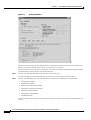
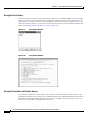
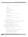
1
Cisco PGW 2200 Softswitch Release 9.8
Operations, Maintenance, and
Troubleshooting Guide
March 7, 2011
Americas Headquarters
Cisco Systems, Inc.
170 West Tasman Drive
San Jose, CA 95134-1706
USA
http://www.cisco.com
Tel: 408 526-4000
800 553-NETS (6387)
Fax: 408 527-0883
Text Part Number: OL-0800-14
THE SPECIFICATIONS AND INFORMATION REGARDING THE PRODUCTS IN THIS MANUAL ARE SUBJECT TO CHANGE WITHOUT NOTICE. ALL
STATEMENTS, INFORMATION, AND RECOMMENDATIONS IN THIS MANUAL ARE BELIEVED TO BE ACCURATE BUT ARE PRESENTED WITHOUT
WARRANTY OF ANY KIND, EXPRESS OR IMPLIED. USERS MUST TAKE FULL RESPONSIBILITY FOR THEIR APPLICATION OF ANY PRODUCTS.
THE SOFTWARE LICENSE AND LIMITED WARRANTY FOR THE ACCOMPANYING PRODUCT ARE SET FORTH IN THE INFORMATION PACKET THAT
SHIPPED WITH THE PRODUCT AND ARE INCORPORATED HEREIN BY THIS REFERENCE. IF YOU ARE UNABLE TO LOCATE THE SOFTWARE LICENSE
OR LIMITED WARRANTY, CONTACT YOUR CISCO REPRESENTATIVE FOR A COPY.
The Cisco implementation of TCP header compression is an adaptation of a program developed by the University of California, Berkeley (UCB) as part of UCB’s public
domain version of the UNIX operating system. All rights reserved. Copyright © 1981, Regents of the University of California.
NOTWITHSTANDING ANY OTHER WARRANTY HEREIN, ALL DOCUMENT FILES AND SOFTWARE OF THESE SUPPLIERS ARE PROVIDED “AS IS” WITH
ALL FAULTS. CISCO AND THE ABOVE-NAMED SUPPLIERS DISCLAIM ALL WARRANTIES, EXPRESSED OR IMPLIED, INCLUDING, WITHOUT
LIMITATION, THOSE OF MERCHANTABILITY, FITNESS FOR A PARTICULAR PURPOSE AND NONINFRINGEMENT OR ARISING FROM A COURSE OF
DEALING, USAGE, OR TRADE PRACTICE.
IN NO EVENT SHALL CISCO OR ITS SUPPLIERS BE LIABLE FOR ANY INDIRECT, SPECIAL, CONSEQUENTIAL, OR INCIDENTAL DAMAGES, INCLUDING,
WITHOUT LIMITATION, LOST PROFITS OR LOSS OR DAMAGE TO DATA ARISING OUT OF THE USE OR INABILITY TO USE THIS MANUAL, EVEN IF CISCO
OR ITS SUPPLIERS HAVE BEEN ADVISED OF THE POSSIBILITY OF SUCH DAMAGES.
Cisco and the Cisco Logo are trademarks of Cisco Systems, Inc. and/or its affiliates in the U.S. and other countries. A listing of Cisco's trademarks can be found at
www.cisco.com/go/trademarks. Third party trademarks mentioned are the property of their respective owners. The use of the word partner does not imply a partnership
relationship between Cisco and any other company. (1005R)
Cisco PGW 2200 Softswitch Release 9.8 Operations, Maintenance, and Troubleshooting Guide
Copyright © 2007–2011, Cisco Systems, Inc. All rights reserved.
C O N T E N T S
Preface
xvii
Document Objectives
Audience
i-xvii
i-xvii
Related Documentation
i-xvii
Obtaining Documentation and Submitting a Service Request
Document Change History
CHAPTER
1
i-xviii
i-xviii
Cisco PGW 2200 Softswitch Platform Overview
1-1
Cisco PGW 2200 Softswitch Platform 1-1
Cisco PGW 2200 Softswitch 1-1
Sun UNIX Hosts 1-2
Cisco SS7 Interfaces 1-2
Cisco ITP-Ls 1-2
Cisco ITPs 1-2
Cisco Switches 1-2
Ethernet Connections 1-3
Cisco PGW 2200 Softswitch Software Architecture
Input/Output Subsystem 1-6
Agent Management Subsystem 1-7
Fault Tolerance Subsystem 1-8
Execution Environment Process Shell 1-9
Call Engine Process 1-9
Call Instance Component 1-10
1-4
Cisco PGW 2200 Softswitch Software Directory Structure
CHAPTER
2
1-11
Cisco PGW 2200 Softswitch Platform Component Startup and Shutdown Procedures
Cisco PGW 2200 Softswitch Startup Procedures 2-2
Starting the Cisco PGW 2200 Softswitch Hardware 2-2
Starting the Cisco PGW 2200 Softswitch Software 2-2
Starting the Cisco PGW 2200 Softswitch Software Manually
Cisco SS7 Interface Startup Procedure
Cisco Switch Startup Procedure
2-1
2-3
2-3
2-4
Cisco PGW 2200 Softswitch Shutdown Procedure 2-4
Shutting Down the Cisco PGW 2200 Softswitch Software Manually
2-4
Cisco PGW 2200 Softswitch Release 9.8 Operations, Maintenance, and Troubleshooting Guide
OL-0800-14
iii
Contents
Shutting Down the Cisco PGW 2200 Softswitch Hardware
Cisco SS7 Interface Shutdown Procedure
Cisco Switch Shutdown Procedure
CHAPTER
3
2-5
2-5
2-6
Cisco PGW 2200 Softswitch Platform Operations
3-1
Daily Tasks 3-1
Starting an MML Session 3-2
Verifying the Platform State of the Cisco PGW 2200 Softswitches 3-2
Verifying That Processes Are Running 3-4
Understanding Processes 3-5
Monitoring the Alarms Status 3-7
Understanding Alarms 3-7
An Alarm Example 3-8
Verifying the Status of all Signaling Services 3-9
Understanding the Signaling Service State Information 3-10
Verifying State of all SS7 Routes 3-12
Understanding the SS7 Route State Information 3-13
Verifying CIC States 3-15
Understanding CIC States 3-16
Verifying System Statistics 3-18
Verifying the Number of Active Processes 3-19
Verifying the Number of Users 3-21
Verifying Available Virtual Memory 3-21
Verifying Available Memory on the Cisco ITP-Ls 3-22
Periodic Maintenance Procedures 3-23
Automatic Disk Space Monitoring 3-24
Configuring Disk Monitor 3-26
Automatic System Log Rotation 3-28
Rotating System Logs Manually 3-28
Creating a Disaster Recovery Plan 3-28
Backing Up System Software 3-29
Backup Procedures for Cisco PGW 2200 Softswitch Software
Processing a Core Dump File 3-38
3-30
Regular Operations 3-38
Managing MML Sessions 3-39
Displaying Previously Entered MML Commands 3-39
Displaying Information About MML Commands 3-40
Re-entering Previously Entered MML Commands 3-41
Retrieving Active MML Sessions 3-42
Cisco PGW 2200 Softswitch Release 9.8 Operations, Maintenance, and Troubleshooting Guide
iv
OL-0800-14
Contents
Ending an MML Session 3-42
Managing Signaling Channels 3-42
Retrieving Signaling Service States 3-45
Retrieving Service State of C7/SS7 Links or Linksets 3-45
Retrieving the Service State for IP Links 3-46
Retrieving the Service State for IP Routes 3-46
Retrieving the Service State of D-Channels 3-47
Retrieving the State of SS7 Signaling Services 3-48
Retrieving the State of SS7 Routes 3-49
Retrieving the State of All Local Subsystem Numbers 3-49
Retrieving the Service State for Associations 3-50
Retrieving TCAP Transactions 3-51
Clearing TCAP Transactions 3-51
Enabling Group Service Reset Messages 3-51
Managing Bearer Channels 3-52
Verifying Proper Replication of Calls 3-52
Retrieving the States of Bearers Held By a Media Gateway 3-53
Blocking CICs 3-55
Retrieving the Administrative State 3-55
Retrieving DPNSS Virtual Bearer Channel Status 3-59
Managing SIP Communications 3-60
Managing the DNS Cache 3-60
Retrieving SIP Call Information 3-62
Provisioning a Cisco PGW 2200 Softswitch 3-64
Starting a Provisioning Session 3-64
Saving and Activating your Provisioning Changes 3-65
Ending a Provisioning Session Without Activating your Changes 3-66
Invoking Dynamic Reconfiguration 3-66
Retrieving Provisioning Data 3-69
Provisioning a Dial Plan 3-75
Importing Provisioning Data 3-75
Exporting Provisioning Data 3-76
Managing Automatic Congestion Control 3-77
Managing a Cisco PGW 2200 Softswitch Platform 3-95
Performing a Manual Switchover 3-96
Verifying Successful Completion of a Switchover 3-97
Verifying the Patch Level of the Cisco PGW 2200 Softswitch 3-100
Retrieving the Logging Level of Software Processes 3-102
Retrieving System Statistics 3-103
Managing System Measurements 3-105
Cisco PGW 2200 Softswitch Release 9.8 Operations, Maintenance, and Troubleshooting Guide
OL-0800-14
v
Contents
Retrieving Measurements 3-105
Clearing Measurements 3-106
Retrieving Link or Linkset Measurements 3-106
Retrieving SS7 Signaling Point Measurements 3-108
Retrieving Measurement Thresholds 3-117
Modifying Measurement Thresholds 3-117
Managing Call Detail Records 3-118
Converting Individual CDR Files to ASCII Format 3-118
Converting Individual CDR Files to a Readable Format 3-118
Using the Cisco MGC Viewer Toolkit 3-119
Launching the Cisco MGC Toolbar 3-120
Using the Alarm Viewer 3-121
Using the Call Detail Record Viewer 3-123
Using the Config-Lib Viewer 3-127
Using the Log Viewer 3-128
Using the Measurement Viewer 3-131
Using the Trace Viewer 3-134
Using the Translation Verification Viewer 3-134
Using the File Options Viewer 3-140
Using the MGC Backup Viewer 3-141
Using the MGC Restore Viewer 3-141
CHAPTER
4
Maintenance and Troubleshooting Overview
Maintenance Strategy Overview
4-1
4-1
Troubleshooting Strategy Overview 4-2
Symptoms, Problems, and Solutions 4-2
General Problem-Solving Model 4-2
System Troubleshooting Tools 4-4
Alarms 4-4
Call Traces 4-4
System Logs 4-4
MML Queries 4-5
Cisco Internetwork Management Tools 4-5
Cisco SS7 Interface Diagnostic Commands 4-7
Third-Party Troubleshooting Tools 4-9
Volt-Ohm Meters, Digital Multimeters, and Cable Testers
Breakout Boxes, Fox Boxes, and BERTs/BLERTs 4-10
Network Monitors and Analyzers 4-10
TDRs and OTDRs 4-11
4-9
Cisco PGW 2200 Softswitch Release 9.8 Operations, Maintenance, and Troubleshooting Guide
vi
OL-0800-14
Contents
CHAPTER
5
Maintaining the Cisco PGW 2200 Softswitch
5-1
Checking Equipment Status 5-1
LEDs 5-2
Sun Netra T 1120/1400 and Sun Netra T 1125/1405
Sun Netra X4270 5-2
Sun Fire X4640 5-2
Maintaining Technical Support Staff 5-2
Skill Level of Personnel 5-2
Staff Software Troubleshooting Tools
5-2
5-3
Maintaining Components 5-3
Software Upgrades 5-3
CHAPTER
6
Troubleshooting the Cisco PGW 2200 Softswitch Platform
Troubleshooting Overview 6-1
Cisco ITP-L Failure 6-2
Cisco PGW 2200 Softswitch Failure
Operating System Failure 6-2
6-1
6-2
Troubleshooting Using Cisco PGW 2200 Softswitch Alarms
Retrieving All Active Alarms 6-3
Acknowledging Alarms 6-3
Alarm Troubleshooting Procedures 6-4
All Conn Cntl Links Fail 6-4
All C7 IP Links Fail 6-5
All ISDN BRI IP Conn Fail 6-6
All ISDN IP Conn Fail 6-7
All M3UAKEY Ack Pending 6-8
All M3UA Assoc Fail 6-9
All SUAKEY Ack Pending 6-10
All SUA Assoc Fail 6-11
ANAL: ALoopCtrExceeded 6-12
ANAL: ATableFail_GetDigMod 6-12
ANAL: ATableFail_GetResult 6-13
ANAL: ATableFlt_DgtRangeError 6-13
ANAL: BLoopCtrExceeded 6-14
ANAL: BNum_GetFail_SrvcTbl 6-14
ANAL: BNum_MdfyBFail_ AnnounceID 6-14
ANAL: BTableFail_GetDigTree 6-15
ANAL: BTableFail_GetDigMod 6-15
ANAL: BTableFail_GetResult 6-15
6-3
Cisco PGW 2200 Softswitch Release 9.8 Operations, Maintenance, and Troubleshooting Guide
OL-0800-14
vii
Contents
ANAL: BTableFlt_DgtRangeError 6-16
ANAL: Cause_GetFail_CauseTbl 6-16
ANAL:Cause_GetFail_DigModTbl 6-17
ANAL: Cause_GetFail_InvldRsltType 6-17
ANAL:Cause_GetFail_LocTbl 6-17
ANAL:Cause_GetFail_RsltTbl 6-18
ANAL:Cause_InvldRslts_CauseTbl 6-18
ANAL: Cause_MdfyBFail_AnnounceID 6-19
ANAL: Cause_MdfyBFail_AppPtInvld 6-19
ANAL: Cause_Rte_LoopDetected 6-20
ANAL: CustId/StartIdx Missing 6-20
ANAL:DataBaseAccessFail 6-21
ANAL: Data Failure Rcvd 6-22
ANAL:dpselection_table_fail 6-22
ANAL:getDialplanBase_fail 6-22
ANAL: InvalidtrkGrpType 6-22
ANAL: Prof_GetFail_DigModTbl 6-23
ANAL: Prof_GetFail_InvldRslt 6-23
ANAL: Prof_GetFail_NOATbl 6-23
ANAL: Prof_GetFail_NOATbl_A 6-24
ANAL: Prof_GetFail_NPITbl 6-24
ANAL: Prof_GetFail_NPITbl_A 6-25
ANAL: Prof_GetFail_RsltTbl 6-25
ANAL: Prof_InvldNPAValue 6-26
ANAL: Prof_InvRslts_NOATbl 6-26
ANAL: Prof_InvRslts_NOATbl_A 6-26
ANAL: Prof_MdfyBFail_AppPtInvld 6-27
ANAL: RteStartIndexInvalid 6-27
ANAL: Rte_TableHopCtrExceeded 6-28
ANAL: RteTableFail_GetRteList 6-28
ANAL: RteTableFail_GetTrkAttrdata 6-29
ANAL: RteTableFail_GetTrkGrpdata 6-29
ANAL: RteTableFail_GetTrunkList 6-29
ANAL: TableFail_BearerCapTable 6-29
ANAL: TableFail_CondRouteDescTable 6-30
ANAL: TableFail_CondRouteTable 6-30
ANAL: TableFail_CPCTable 6-30
ANAL: TableFail_RouteHolTable 6-31
ANAL: TableFail_PercRouteTable 6-31
ANAL: TableFail_TMRTable 6-31
Cisco PGW 2200 Softswitch Release 9.8 Operations, Maintenance, and Troubleshooting Guide
viii
OL-0800-14
Contents
ANAL: TableFail_TNSTable 6-32
ANAL: TrunkGrpRsltCtrExceeded 6-32
Association Degraded 6-32
Association Fail 6-33
C7LNK ALGNMT LOST 6-33
C7DPC CONGESTION 6-33
C7LNK CONGESTION 6-34
C7LNK INHIBIT 6-34
C7SLTLnkCong 6-34
Call Back Feature Insertion Failure 6-35
Call Back Feature Deletion Failure 6-35
Charge Table Access Failure 6-35
Charge Table Load Failure 6-35
Comm Srvc Creation Error 6-36
Config Fail 6-37
CTI Connection Failed 6-37
CTI Version Mismatch 6-38
Dial Plan Loading Failed 6-38
DISK 6-38
EISUP: Unexpected Msg/Par 6-39
ENGINE CONFIG FAIL 6-39
FAIL 6-40
FailoverPeerLost 6-41
FailoverPeerOOS 6-41
FAIL REMOTE STANDBY 6-42
FORCE NODE RESTART 6-42
Gen Fail 6-43
Holiday Table Access Failure 6-44
Holiday Table Load Failure 6-44
INVALID M3UA RC 6-45
INVALID SUA RC 6-45
Invalid Virtual_IP_Addr 6-46
IP CONNECTION FAILED 6-46
IP RTE CONF FAIL 6-47
IP RTE FAIL 6-47
ISUP: COT Failure 6-48
License server unreachable 6-49
LIF BER 6-49
LIF FAIL 6-50
LIF LOF 6-51
Cisco PGW 2200 Softswitch Release 9.8 Operations, Maintenance, and Troubleshooting Guide
OL-0800-14
ix
Contents
LIF LOS 6-51
LIF SES 6-52
LIF YELLOW 6-52
LIF: IDLE CHANGE 6-53
LIF: LOST CD 6-53
LIF: LOST CTS 6-54
M3UAKEY Ack Pending 6-54
MeterPulseTariff Table Load Failure 6-55
MMDB: Database unavailable 6-56
MMDB: Database cause switchover 6-56
MMDB: Database nearly full 6-56
NAS: AuditResponse Failure 6-56
NAS: CommsFailure 6-57
NAS: ResourceFailure 6-58
OLC: Leg1chanSeizedUnpackError 6-58
OLC: Leg1chanModifiedUnpackError 6-58
OLC: Leg1chanDeletedUnpackError 6-59
OLC: Leg1notifyUnpackError 6-59
OLC: Leg1deleteChanUnpackError 6-60
OLC: Leg1notifyRequestAckUnpackError 6-61
OLC: Leg1chanOpsFailed 6-61
OOS TRAFFIC RE-ROUTE 6-62
OverloadHeavy 6-62
OverloadMedium 6-63
OverloadLight 6-63
OverResIncomingThreshold 6-64
PC UNAVAIL 6-65
Peer IP Links Failure 6-65
PEER LINK A FAILURE 6-66
PEER LINK B FAILURE 6-66
PEER MODULE FAILURE 6-66
POM INACTIVITY TIMEOUT 6-66
POM SESSION TERMINATE 6-67
POM: DynamicReconfiguration 6-67
POM: PEER_SYNC_ERR 6-67
PRI: B-Channel not available 6-68
ProcM No Response 6-68
ProtocolFileMissing 6-69
REPL: all connections failure 6-69
RSET CONFIG FAIL 6-70
Cisco PGW 2200 Softswitch Release 9.8 Operations, Maintenance, and Troubleshooting Guide
x
OL-0800-14
Contents
SC CONFIG FAIL 6-71
SC FAIL 6-71
SC M-OOS 6-72
SG Node Interface Fail 6-72
SG Pair Interface Fail 6-72
SIP: DNS CACHE NEARLY FULL 6-73
SIP: DNS SERVICE OOS 6-73
SIP: OOS 6-74
SIP Service Fail Over 6-74
Standby Warm Start 6-75
SS7 RTE KEY FAIL 6-76
SS7 SIG SRVC CONFIG FAIL 6-76
SS7 SIG SRVC UNAVAIL 6-77
SSN FAIL 6-78
SUAKEY Ack Pending 6-78
SUPPORT FAILED 6-79
SwitchoverFail 6-80
Tariff Table Access Failure 6-80
Tariff Table Load Failure 6-80
TLC: Leg2chanSeizedUnpackError 6-80
TLC: Leg2chanModifiedUnpackError 6-81
TLC: Leg2chanDeletedUnpackError 6-81
TLC: Leg2notifyUnpackError 6-82
TLC: Leg2deleteChanUnpackError 6-82
TLC: Leg2notifyRequestAckUnpackError 6-82
TLC: Leg2chanOpFailed 6-83
UCM: CCodeModfailed 6-83
UCM: MGCPDIALAuthFail 6-86
Virtual_IP_Addr Mismatch 6-87
Wrong IP Path 6-88
XE Rsrc Fail 6-89
Troubleshooting with System Logs 6-89
Viewing System Logs 6-90
Understanding System Log Messages 6-91
Changing the Log Level for Processes 6-91
Creating a Diagnostics Log File 6-93
Collecting System Data for Cisco TAC 6-93
Resolving SS7 Network Related Problems
Signaling Channel Problems 6-95
SS7 Link is Out-of-Service 6-96
6-94
Cisco PGW 2200 Softswitch Release 9.8 Operations, Maintenance, and Troubleshooting Guide
OL-0800-14
xi
Contents
SS7 Load Sharing Malfunction 6-97
Physical Layer Failures 6-98
Configuration Errors 6-98
Supporting Entity Failures 6-99
Incomplete Signaling 6-99
Changing Service States 6-99
Signaling Destination Problems 6-100
Bouncing SS7 Links 6-101
Configuration Errors 6-101
Traffic Restart 6-102
SS7 Destination is Out of Service 6-102
SS7 Route is Out of Service 6-102
SS7 Destination is Unavailable 6-103
Signaling Channel Troubleshooting Procedures 6-103
Setting the Service State of a Signaling Service 6-103
Setting the Service State of an SS7 Signaling Service 6-104
Setting the Service State of a C7/SS7 Link or Linkset 6-105
Setting the Service State of an IP Link 6-105
Setting the Service State of an IP Route 6-106
Setting the Service State of a D-channel 6-106
Setting the Service State of a Local Subsystem Number 6-107
Setting the Service State of an Association 6-107
Verifying MTP Timer Settings 6-107
Modifying Configurable Timers 6-109
Managing Japanese SS7 Signaling Link Tests 6-118
Managing Japanese SS7 Signaling Route Tests 6-119
Verifying Proper Loading of a Dial Plan 6-121
Verifying Configuration to Support Multiple Versions of SS7 6-121
Resolving an Association Alarm 6-122
Converting Stored and Sent Point Code Values 6-122
Resolving Bearer Channel Connection Problems 6-123
Setting the Administrative State 6-124
Setting the Administrative State of a Cisco PGW 2200 Softswitch
Setting the Administrative State of a Media Gateway 6-125
Setting the Administrative State of a Trunk Group 6-125
Setting the Administrative State of a Signaling Service 6-126
Setting the Administrative State of Spans 6-127
Setting the Administrative State of CICs 6-128
Querying Local and Remote CIC States 6-129
Resolving Local and Remote CIC State Mismatch 6-131
6-124
Cisco PGW 2200 Softswitch Release 9.8 Operations, Maintenance, and Troubleshooting Guide
xii
OL-0800-14
Contents
Performing CIC Validation Tests 6-131
Resolving ISDN D-Channel Discrepancies 6-137
Unblocking CICs 6-139
Unblocking Locally Blocked CICs 6-139
Unblocking Remotely Blocked CICs 6-140
Resetting CICs 6-140
Resolving Stuck CICs 6-141
Manually Resolving Stuck CICs 6-142
Auditing Call States 6-144
Stopping Calls 6-144
Stopping Calls on a Cisco PGW 2200 Softswitch 6-145
Stopping Calls on a Media Gateway 6-145
Stopping Calls on a Trunk Group 6-145
Stopping Calls on a Signaling Service 6-145
Stopping Calls on Spans 6-146
Stopping Calls on CICs 6-147
Auditing an MGCP Media Gateway 6-148
Starting an MGCP Media Gateway Audit 6-148
Retrieving an MGCP Media Gateway Audit 6-148
Running a Manual Continuity Test 6-149
Verifying Continuity Test Settings 6-149
Media Gateway IP Destination or Link Out-of-Service 6-151
Calls Fail at the Cisco PGW 2200 Softswitch 6-152
3.1 kHz (ISDN Category 3) Calls are Failing 6-153
Calls are Misrouting 6-154
Resolving SIP Communication Problems
Stopping SIP-to-SIP Calls 6-155
6-155
Tracing 6-155
Performing a Call Trace 6-156
Starting A Call Trace 6-156
Starting A Call Trace (on Release 9.7(3) Patch 8) 6-158
Stopping A Call Trace 6-161
Retrieving Names of Open Call Trace Files 6-161
Viewing the Call Trace 6-162
Deleting Call Trace Files 6-163
Understanding the Call Trace 6-163
Alternatives to Call Tracing 6-165
Diagnosing Hung Calls 6-165
Performing an Abnormal Call Termination Trace 6-167
Performing a TCAP Trace 6-168
Cisco PGW 2200 Softswitch Release 9.8 Operations, Maintenance, and Troubleshooting Guide
OL-0800-14
xiii
Contents
Platform Troubleshooting 6-169
Verifying Cisco PGW 2200 Softswitch Ethernet Operation 6-169
Deleting Unnecessary Files to Increase Available Disk Space 6-169
Recovering from a Switchover Failure 6-170
Recovering from Cisco PGW 2200 Softswitch Failure 6-172
Recovering from a Cisco PGW 2200 Softswitch Failure in a Simplex System 6-173
Recovering from a Single Cisco PGW 2200 Softswitch Failure in a Continuous Service
System 6-175
Recovering from a Dual Cisco PGW 2200 Softswitch Failure in a Continuous Service
System 6-176
Restoring Stored Configuration Data 6-177
Restoring Procedures for Cisco PGW 2200 Softswitch Software 6-177
Verifying Proper Configuration of Replication 6-179
Configuration Export Failed Because of MMDB 6-180
Measurements Are Not Being Generated 6-180
Call Detail Records Are Not Being Generated 6-181
Resolving a Failed Connection to a Peer 6-181
Rebooting Software to Modify Configuration Parameters 6-183
Diagnosing SNMP Failure 6-184
Correcting the System Time 6-185
NTP is Not Used and the Cisco PGW 2200 Softswitch is Not the Source of the CDRs 6-186
NTP is Not Used and Cisco PGW 2200 Softswitch is the Source of the CDRs 6-186
NTP is Used and the Cisco PGW 2200 Softswitch is the Source of the CDRs 6-187
Securing Your Network 6-187
Securing the Cisco PGW 2200 Softswitch 6-187
Securing Cisco BAMS 6-189
TIBCO Interface Not Working 6-195
Installing the License File 6-197
Replacing a Failed Disk 6-197
APPENDIX
A
Configuring Cisco PGW 2200 Softswitch Log Files
Understanding Logging Files
A-1
A-1
Configuring the Data Dumper A-2
Configuring the Data Dumper to Support BAMS A-4
Understanding the Format of Log Files Archived Using Data Dumper
APPENDIX
B
Troubleshooting Cisco ITP-L Signaling
A-5
B-1
Cisco ITP-L Signaling Overview B-2
IP Signaling Backhaul B-2
Types of Encapsulation B-2
Cisco PGW 2200 Softswitch Release 9.8 Operations, Maintenance, and Troubleshooting Guide
xiv
OL-0800-14
Contents
PDU Verb Types B-2
Backhaul Message IDs B-3
Connection Management B-3
Backhaul Statistics B-4
Backhaul Congestion B-4
Link Status B-5
Troubleshooting SS7 Link Problems B-5
Checking Link Configuration Files B-5
Checking UDP Traffic Flows B-6
Checking Connection between Cisco PGW 2200 Softswitch and Cisco ITP-L
Checking the T1/E1 Link State B-6
Verifying the Link Alignment Status B-6
Verifying Exchanged Point Codes B-7
Cross-Checking Configuration Files B-9
B-6
Troubleshooting Cisco ITP-L-to-STP Signaling Links B-11
MTP1 Communication Problems B-12
Identifying MTP1 Communication Problems B-12
Resolving MTP1 Communication Problems B-12
MTP2 Communication Problems B-13
Identifying MTP2 Communication Problems B-13
Resolving MTP2 Communication Problems B-13
Troubleshooting Cisco ITP-L to Cisco PGW 2200 Softswitch Communications B-14
Identifying MTP3 and Higher Layer Problems B-14
Resolving MTP3 and Higher Layer SS7 Communication Problems B-15
Identifying Ethernet Connectivity Problems B-15
Identifying IP Communication Problems B-16
Identifying RUDP Communications Problems B-16
Cisco ITP-L Error Messages
APPENDIX
C
B-17
Troubleshooting Cisco Switch Signaling
VLANs
C-1
C-1
Command Line Interface C-1
Command Line Interface Local Access C-2
Command Line Interface Remote Access C-3
Troubleshooting Virtual Pathways and ISLs
APPENDIX
D
Cisco PGW 2200 Softswitch Measurements
ANSI ISUP Measurements
C-3
D-1
D-32
Cisco PGW 2200 Softswitch Release 9.8 Operations, Maintenance, and Troubleshooting Guide
OL-0800-14
xv
Contents
Cisco PGW 2200 Softswitch Release 9.8 Operations, Maintenance, and Troubleshooting Guide
xvi
OL-0800-14
Preface
Revised: March 7, 2011, OL-0800-14
This preface describes the objectives of this document and explains how to find additional information
on related products and services. It contains the following sections:
•
Document Objectives, page xvii
•
Audience, page xvii
•
Related Documentation, page xvii
•
Obtaining Documentation and Submitting a Service Request, page xviii
•
Document Change History, page xviii
Document Objectives
This document provides instructions for operating, maintaining, and troubleshooting the core elements
of the Cisco PGW 2200 Softswitch platform.
This document covers systems operation and management, signaling channel operation, alarm
management, and problem identification and resolution. Unless otherwise specified, use the procedures
in this document when your Cisco PGW 2200 Softswitch platform is configured with two Cisco PGW
2200 Softswitches to work in continuous service mode.
Audience
The audience for this document are network operators and administrators. This audience are assumed to
have experience in telecommunications networks, protocols, and equipment. They must also be familiar
with data communications networks, protocols, and equipment.
Related Documentation
This document contains information that is related to Cisco PGW 2200 Softswitch operations,
maintenance, and troubleshooting procedures. For additional information on those subjects, see the
documents at:
http://www.cisco.com/en/US/products/hw/vcallcon/ps2027/tsd_products_support_series_home.html
Cisco PGW 2200 Softswitch Release 9.8 Operations, Maintenance, and Troubleshooting Guide
OL-0800-14
xvii
Preface
Obtaining Documentation and Submitting a Service Request
You can also find the Cisco PGW 2200 Softswitch Documentation Map at the following URL:
http://www.cisco.com/en/US/products/hw/vcallcon/ps2027/
products_documentation_roadmaps_list.html
Other useful reference publications include:
•
Overviews of the related telephony solutions—Describe the Cisco telephony solutions with which
the Cisco PGW 2200 Softswitch node is associated.
•
Provisioning guides for the related telephony solutions—Describe the provisioning steps for the
Cisco telephony solutions with which the Cisco PGW 2200 Softswitch node is associated.
•
Solution gateway installation and configuration guides—Describe the steps for installing and
configuring the media gateway for a particular Cisco telephony solution.
•
Cisco IP Transfer Point–LinkExtender—Describes the Cisco IP Transfer Point–LinkExtender
(Cisco IPT-L, formerly known as the Cisco Signaling Link Terminal or Cisco SLT) and provides
configuration information.
Obtaining Documentation and Submitting a Service Request
For information on obtaining documentation, submitting a service request, and gathering additional
information, see the monthly version of the document What’s New in Cisco Product Documentation,
which also lists all new and revised Cisco technical documentation at:
http://www.cisco.com/en/US/docs/general/whatsnew/whatsnew.html
Subscribe to What’s New in Cisco Product Documentation as a Really Simple Syndication (RSS) feed and
set content to be delivered directly to your desktop using a reader application. The RSS feeds are a free service
and Cisco currently supports RSS version 2.0.
Document Change History
Release Number
Document Number
Change Date
Change Summary
9.8(1)
OL-0800-14
March 2011
Updated hardware platform information in Chapter 5.
9.8(1)
OL-0800-13
April 2010
Deleted two former chapters:
•
Former Chapter 6 provided information about
Cisco routers that supported operation of the Cisco
IP Transfer Point—LinkExtender (ITP-L). The
documented routers are no longer sold.
The document now includes references to routers
that currently support the Cisco ITP-L product.
9.8(1)
OL-0800-12
December 2009
•
Former Chapter 7 provided information about the
Cisco Catalyst 5500 Multiswitch Router. That
product is no longer sold.
•
Modified the description of the operation of disk
monitor in Chapter 3 on pages 3-24 and 3-25.
Added new information to the section “Managing
Bearer Channels” in Chapter 3.
Cisco PGW 2200 Softswitch Release 9.8 Operations, Maintenance, and Troubleshooting Guide
xviii
OL-0800-14
Preface
Document Change History
Release Number
Document Number
Change Date
Change Summary
9.8(1)
OL-0800-11
March 7, 2011
Corrected the description of the CallSuccess counter in
Appendix D “Cisco PGW 2200 Softswitch
Measurements.”
9.8(1)
OL-0800-10
December 2008
Added new Cisco PGW 2200 Softswitch measurements
in Release 9.8.
9.7(3)
OL-0800-09
May 2008
Updated Cisco PGW 2200 Softswitch troubleshooting
MML commands and system output in Release 9.7.
Added Cisco PGW 2200 Softswitch call trace
enhancement in Release 9.7 Patch 8.
9.7(3)
OL-0800-08
March 2008
Added new Cisco PGW 2200 Softswitch measurements
in Release 9.7 Patch 13.
9.7(3)
OL-0800-07
October 2007
Added new Cisco PGW 2200 Softswitch measurements
in Release 9.5, 9.6 and 9.7.
Cisco PGW 2200 Softswitch Release 9.8 Operations, Maintenance, and Troubleshooting Guide
OL-0800-14
xix
Preface
Document Change History
Cisco PGW 2200 Softswitch Release 9.8 Operations, Maintenance, and Troubleshooting Guide
xx
OL-0800-14
CH A P T E R
1
Cisco PGW 2200 Softswitch Platform Overview
Revised: March 7, 2011, OL-0800-14
This chapter describes the components of the Cisco PGW 2200 Softswitch platform and presents the
software architecture of the Cisco PGW 2200 Softswitch, Release 9.
This chapter includes the following sections:
•
Cisco PGW 2200 Softswitch Platform, page 1-1
•
Cisco PGW 2200 Softswitch Software Architecture, page 1-4
•
Cisco PGW 2200 Softswitch Software Directory Structure, page 1-11
Cisco PGW 2200 Softswitch Platform
The following subsections describe the components of the Cisco PGW 2200 Softswitch platform:
•
Cisco PGW 2200 Softswitch, page 1-1
•
Cisco SS7 Interfaces, page 1-2
•
Cisco Switches, page 1-2
There are several optional elements of the Cisco PGW 2200 Softswitch platform, which are listed in the
“Agent Management Subsystem” section on page 1-7. For more information on these optional elements,
see the documentation for each element.
Cisco PGW 2200 Softswitch
The Cisco PGW 2200 Softswitch is a Sun UNIX box running Cisco PGW 2200 Softswitch software
Release 9. The Cisco PGW 2200 Softswitch performs real-time, call-processing, and SS7-layer
functions; manages trunk resources, alarms, and call routing; and administers billing information.
Cisco PGW 2200 Softswitch functionality includes:
•
Processing calls
•
Originating call detail records (CDRs)
•
Providing alarm initiation information
•
Producing operational peg counts
•
Receiving and processing craft user interface (CUI) data
Cisco PGW 2200 Softswitch Release 9.8 Operations, Maintenance, and Troubleshooting Guide
OL-0800-14
1-1
Chapter 1
Cisco PGW 2200 Softswitch Platform Overview
Cisco PGW 2200 Softswitch Platform
•
Providing Message Transfer Part (MTP) Level 3 (MTP3) functions
•
Providing advanced intelligent network (AIN) capabilities
Sun UNIX Hosts
The Cisco PGW 2200 Softswitch Release 9.8 Software Installation and Configuration Guide identifies
the Sun UNIX hosts that support the releases of the Cisco PGW 2200 Softswitch software.
To attain continuous service and reliability, install and configure two Sun UNIX hosts for system
redundancy. The call-processing application is active on one Cisco PGW 2200 Softswitch and
automatically switches to the standby Cisco PGW 2200 Softswitch only if the active host goes out of
service.
Cisco SS7 Interfaces
The Cisco PGW 2200 Softswitch platform interfaces to an SS7 network through Cisco IP Transfer Point
LinkExtenders (ITP-Ls) or Cisco IP Transfer Points (ITPs).
Cisco ITP-Ls
The Cisco ITP-Ls terminate Message Transfer Part (MTP) levels 1 and 2 of the SS7 protocol.
Cisco routers, for example, the Cisco 2800, backhaul the remaining SS7 layers by running the Reliable
User Datagram Protocol (RUDP) over an Ethernet 10BASE-T or 100BASE-T interface.
The number of signaling network connections available on each Cisco ITP-L depends on the router you
install in the chassis. You can use multiple Cisco ITP-Ls (up to 16 per Cisco PGW 2200 Softswitch
platform) to support signaling channels. You can configure the Cisco ITP-L with redundant connections
to the control signaling network. Redundant connections eliminate the Cisco ITP-L as a possible single
point of failure in the Cisco PGW 2200 Softswitch platform. The Cisco ITP-L supports V.35, T1, and E1
interfaces to the SS7 network.
Cisco ITPs
The Cisco ITPs terminate all levels of MTP and the Service Connection Control Part (SCCP) layer of
the SS7 protocol. The Cisco ITP backhauls the remaining SS7 layers across an IP network to the Cisco
PGW 2200 Softswitch. The Cisco ITP transmits data that conforms to the SIGTRAN standards and MTP
Level 3 User Adaptation (M3UA/SUA). The transmissions also comply with the Stream Control
Transmission Protocol (SCTP) and pass through an Ethernet interface.
The number of signaling network connections on each Cisco ITP depends on the router you use. Refer
to the Release Notes pertaining to the Cisco ITP software for a list of the routers that support the Cisco
ITP and the potential number of signaling network connections.
Cisco Switches
Cisco switches provide the Ethernet backbone for the Cisco PGW 2200 Softswitch platform. You can
deploy LAN and WAN implementations. See the Release Notes pertaining to the Cisco PGW 2200
Softswitch software for a list of the Cisco switches that should be selected to form the Ethernet
backbone.
Cisco PGW 2200 Softswitch Release 9.8 Operations, Maintenance, and Troubleshooting Guide
1-2
OL-0800-14
Chapter 1
Cisco PGW 2200 Softswitch Platform Overview
Cisco PGW 2200 Softswitch Platform
Table 1-1 shows the limitations of the WAN implementations.
Table 1-1
Limitations on WAN Switches Within a Cisco PGW 2200 Softswitch Platform
Condition
Requirement
Software release version
Cisco PGW 2200 Softswitch software 9.3(2) or later
(with associated operating system and hardware
requirements).
Total end-to-end delay, one way (the time Must be less than 150 milliseconds.
required to send a message from a source
to a destination, such as from a Cisco PGW
2200 Softswitch to a Cisco ITP-L)
Packet loss (defined as missing packets
with a message)
Must not exceed 1 percent (preferably, less than 0.5
percent).
Note
Dual-VLAN SIP automatic switchover
support is enabled
For packet loss rates below 0.5 percent, increase
the RUDP receive window size
(*. rudpWindowSz) to 64 to improve
performance.
Both Cisco PGW 2200 Softswitches should be part of the
same IP subnet.
Ethernet Connections
Each Ethernet NIC for each Cisco PGW 2200 Softswitch is connected to a switch through a 100BASE-T
interface. The switches connect to the SS7 interfaces through 10BASE-T or 100BASE-T interfaces.
Figure 1-1 displays the Ethernet connections between the elements of the Cisco PGW 2200 Softswitch
platform.
Cisco PGW 2200 Softswitch Release 9.8 Operations, Maintenance, and Troubleshooting Guide
OL-0800-14
1-3
Chapter 1
Cisco PGW 2200 Softswitch Platform Overview
Cisco PGW 2200 Softswitch Software Architecture
Figure 1-1
Cisco PGW 2200 Softswitch Platform Connectivity
Switch
Fast
Ethernet
100BT
100Base T
100Base T
Active PGW
Ethernet
10BT/100BT
Supervisor
engine
Supervisor
engine
Standby PGW
100Base T
100Base T
Switch
Supervisor
engine
Cisco
ITP
Supervisor
engine
Fast
Ethernet
100BT
SS7 links
to STP
SS7 links
to STP
Cisco
ITP-L
SS7 links
to STP
Cisco
ITP-L
SS7 links
to STP
Ethernet active
Ethernet standby
203201
Ethernet
10BT/100BT
Cisco PGW 2200 Softswitch Software Architecture
This section describes the major subsystems in the Cisco PGW 2200 Softswitch software, which are
illustrated in Figure 1-2. The major subsystems are:
•
Input/Output Subsystem, page 1-6
•
Agent Management Subsystem, page 1-7
•
Fault Tolerance Subsystem, page 1-8
•
Execution Environment Process Shell, page 1-9
•
Call Engine Process, page 1-9
Cisco PGW 2200 Softswitch Release 9.8 Operations, Maintenance, and Troubleshooting Guide
1-4
OL-0800-14
Chapter 1
Cisco PGW 2200 Softswitch Platform Overview
Cisco PGW 2200 Softswitch Software Architecture
Figure 1-2
Cisco PGW 2200 Softswitch Software System Diagram
PGW
I/O subsystem
Event dispatcher queue
INAP
Replicator
Failover
daemon
Fault tolerance
TCAP/SCCP
Call Engine
IOCM
TCAP
SCCP
XE/PXE Process Shell
Data
Manager
Timers Signals
IPC
Log
client
Meas.
client
Alarm
client
Process
Manager
MML
Fault
Alarm Mgr
Terminal
Meas.
Meas. Mgr
Cisco MNM
Cisco VSPT
Config.
Provision
Mgr
IOCC
SS7
SS7
BSMVO
IOCC
SUA
SUA
ITP
(SCCP)
IOCC
M3UA
M3UA
ITP
(MTP)
IOCC
IUA
Agent Management System (AMS)
Config.
Mgr
SNMP client
(GUI)
Master agent
Other clients
(FTP, APL
and so on)
CIAgent
standard
agents
Configuration
IOCC
ISDNL3
Core
applications
Data
dumpers
Measurement
agent
Alarms
CDRs
IUA
DUA
MGW
53xx/5400
MGW
2600/36xx
IOCC
H.248
Operations
agent
ITP-L
(MTP2)
28xx
5350/5400
Meas.
IPFAS
MGW
2600/36xx
MGX 8800
(VXSM/DBE/ 5xxx/72xx
MGX
H.248 7600 Series
8260/8850
Router
IOCC
Q931+
NAS
IOCC
MGCP
MGCP
IOCC
SIP
SIP
IOCC
E-ISUP
MGC
H323
MGW
36xx/5xxx/7200
MGX 8260
MGW
26xx/36xx
5xxx/7200
MGX 8260/8850
SIP
Endpoint
Peer
PGW
ñ OS process
BAMS
Customer
billing
ñ PGW function
Note
205459
HSI
Legend
The H.248 IOCC in the I/O subsystem (in Figure 1-2) became available in Cisco PGW 2200 Softswitch
software Release 9.7(3) Patch 8.
Cisco PGW 2200 Softswitch Release 9.8 Operations, Maintenance, and Troubleshooting Guide
OL-0800-14
1-5
Chapter 1
Cisco PGW 2200 Softswitch Platform Overview
Cisco PGW 2200 Softswitch Software Architecture
Input/Output Subsystem
The I/O subsystem consists of the I/O channel controllers (IOCC) and the I/O channel manager (IOCM),
which manages the controllers.
•
IOCM manages all IOCCs.
•
IOCCs provide:
– Protocol-specific, message-based interface that allows nodes and platforms that are external to
the Cisco PGW 2200 Softswitch to communicate with the Cisco PGW 2200 Softswitch.
– Interface that allows buffering of messages to the call engine event dispatcher queue.
•
The Cisco PGW 2200 Softswitch software I/O subsystem includes the following IOCCs:
– Basic Rate Interface (BRI)—Added in Release 9.5, this IOCC enables the backhaul of Layer 3
QSIG and Q.931 messages in a TCP session. This IOCC operates between a Cisco PGW 2200
Softswitch and voice gateways that support BRI signaling backhaul.
– Digital Private Network Signaling System (DPNSS)—Added in Release 9.4, this IOCC enables
the transparent transport of DPNSS data over IP. This IOCC operates between media gateways
that support DPNSS.
– Extended ISDN User Part (E-ISUP)—Protocol proprietary to Cisco that enables the transport
of endpoint information and media-gateway-specific information between two (or more) Cisco
PGW 2200 Softswitches. This protocol provides an enhanced ISUP base to support all ANSI
and ITU ISUP messaging and elements. It also has additional fields to support the transport of
service information (such as local number portability [LNP], 800 numbers, and so on).
– ISDN Level 3—Provides backhauling of ISDN (standard variants) from a media gateway to a
Cisco PGW 2200 Softswitch.
– ISDN Q.921 User Adaptation Layer (IUA)—Added in Release 9.4, this IOCC enables
backhauling of ISDN Q.921 user messages over IP with the Stream Controlled Transmission
Protocol (SCTP). This IOCC operates between a Cisco PGW 2200 Softswitch and media
gateways.
– Media Gateway Control Protocol (MGCP)—Enables communication with media gateways and
trunking gateways. This protocol enables you to set up and configure bearer channel
connections on the Cisco PGW 2200 Softswitch for call control environments.
– Message Transfer Part Level 3 (MTP3) User Adaptation (M3UA)—Added in Release 9.4, this
IOCC enables the transport of any SS7 MTP Level 3 User signaling (for example, ISUP and
TUP messages) over IP with SCTP. This IOCC operates between a Cisco PGW 2200 Softswitch
and a Cisco IP Transfer Point (ITP).
– Q.931+—A stateless IOCC, for a protocol proprietary to Cisco, which is a special version of
ISDN that enables forward hauling of Q931+ signaling to a media gateway. You configure this
IOCC on a Cisco PGW 2200 Softswitch for signaling environments.
– Session Initiation Protocol (SIP)—Enables the Cisco PGW 2200 Softswitch to receive and send
SIP messages over the User Datagram Protocol (UDP).
– Signaling Control Connection Part (SCCP) User Adaptation (SUA)—Added in Release 9.4, this
IOCC enables the transport of any SCCP user signaling (for example, TCAP messages) over IP
with SCTP. This IOCC operates between a Cisco PGW 2200 Softswitch and a Cisco ITP.
– Signaling System 7 (SS7)—Contains MTP3, which backhauls SS7 signaling from a Cisco IP
Transfer Point LinkExtender (ITP-L) to the Cisco PGW 2200 Softswitch.
Cisco PGW 2200 Softswitch Release 9.8 Operations, Maintenance, and Troubleshooting Guide
1-6
OL-0800-14
Chapter 1
Cisco PGW 2200 Softswitch Platform Overview
Cisco PGW 2200 Softswitch Software Architecture
Agent Management Subsystem
The agent management subsystem (AMS) allows external client software or terminals to gain access to
the data in the Cisco PGW 2200 Softswitch. This subsystem supports the following functions:
•
Configuration management—Enables you to add, delete, or modify parameters and resources on the
Cisco PGW 200 Softswitch so that it can perform its switching function. This data is stored locally
in data (.dat) files. This data is required to automate reconfiguration after a process failure.
•
Alarm management—Reports and clears alarms generated by Cisco PGW 2200 Softswitch
processes.
•
Performance measurement management—Reports and clears metrics that are generated by Cisco
PGW 2200 Softswitch processes. You can also define thresholds which, if exceeded, could produce
alarms.
•
Accounting management—Dumps generated CDRs to locally persistent files or to remote databases
through a standard or customized API.
The following types of external clients can access or manipulate data on the Cisco PGW 2200
Softswitch:
•
Man-Machine Language (MML) terminal—Serves as a command-line interpreter. An operator can
issue commands to manipulate data for fault detection, measurements, or configuration. MML is
similar to TL/1, which enables low-level system experts (such as operations personnel) to perform
rapid system configuration or troubleshooting.
•
SNMP-based terminal—Enables you to use SNMP to access network data. You can use the data to
manage system performance, to collect measurements, and to maintain security. The Cisco PGW
2200 Softswitch has a master agent (EMANATE from SNMP Research), which includes the
following subagents that provide SNMP access to the system:
– Operations—Custom subagent that provides access to fault data.
– Measurement—Custom subagent that provides access to measurement data.
– Critical application monitor—Standard CIAgent subagent that monitors the process manager
(procM) process.
– Host resources MIB—Standard CIAgent subagent that accesses data, such as the number of
processors, and memory usage in the Cisco PGW 2200 Softswitch.
– MIB-II—Standard CIAgent subagent that partially supports the MIB-II standard (RFC-1213).
– File system monitor—Standard CIAgent subagent that monitors thresholds for five file systems.
•
TIBCO management system—Introduced in Release 9.5(2), the Cisco PGW 2200 Softswitch
TIBCO interface enables you to use a TIBCO management system to add, modify, delete, and
retrieve provisioning data on the Cisco Cisco PGW 2200 Softswitch. The Cisco PGW 2200
Softswitch supports TIBCO Version 6 daemons and libraries. When this interface is enabled, the
Cisco PGW 2200 Softswitch can communicate with one of two TIBCO daemons on your
management system:
– Rendezvous Daemon (RVD)—Used when the management system is in the same network as the
Cisco PGW 2200 Softswitch. The TIBCO adapter on the Cisco PGW 2200 Softswitch
automatically starts RVD on the management system unless either the RVD or Routing Daemon
(RVRD) is already running.
Cisco PGW 2200 Softswitch Release 9.8 Operations, Maintenance, and Troubleshooting Guide
OL-0800-14
1-7
Chapter 1
Cisco PGW 2200 Softswitch Platform Overview
Cisco PGW 2200 Softswitch Software Architecture
– Rendezvous Routing Daemon (RVRD)—Used when the management system and the Cisco
PGW 2200 Softswitches are not on the same network. You must configure the RVRD routing
table and start RVRD manually before activating the interface on the Cisco PGW 2200
Softswitch. See the TIBCO user documentation for information on configuring the RVRD
routing table.
Note
Typically, you activate the TIBCO interface during initial installation or during an
upgrade. For more information on activating the TIBCO interface, see Cisco PGW 2200
Softswitch Software Release 9 Installation and Configuration Guide.
•
Cisco MGC Node Manager (MNM)—Optional application for network element management.
•
Cisco Voice Services Provisioning Tool (VSPT)—Optional application for provisioning the Cisco
PGW 2200 Softswitch.
•
Billing and Measurements Server (BAMS)—Optional application for collecting CDRs and
operational measurements.
•
H.323 Signaling Interface (HSI)—Optional application that provides an interface to H.323
networks.
Fault Tolerance Subsystem
The fault tolerance subsystem exists to preserve calls if the Cisco PGW 2200 Softswitch encounters a
fault condition. There are two processes that ensure this:
•
Switchover daemon—Monitors Cisco PGW 2200 Softswitch processes by using a heartbeat
mechanism. If the switchover daemon receives no response to its process polling in a fault-tolerant
hardware configuration, the control transfers to the standby unit.
•
Replicator—Allows processes to checkpoint critical call information, such as signaling and bearer
states, as well as call data across the active and standby processors. The replicator duplicates enough
information to enable established calls to survive a switchover. Checkpointing events are generated
at two points in a call:
– When the call is answered, to update the full duplex path.
– When the call is released, after the physical resources are de-allocated.
An operator who is performing maintenance by issuing MML commands using an SNMP client, or
by circuit supervision, can generate connectionless (noncall) signaling.
Certain signaling can also generate checkpointing events:
– Blocking or unblocking of circuits
– Circuit reset
Note
The replicator mechanism does not try to replicate program or data storage. Service features are not
checkpointed across processors; there is just enough information to maintain the voice or data path
between the call originator and the call terminator.
If a switchover occurs before the voice path is established during call processing, the call cannot be
checkpointed to the standby Cisco PGW 2200 Softswitch. Calls that are not established during call setup
are lost in the Cisco PGW 2200 Softswitch that becomes active after the switchover.
Cisco PGW 2200 Softswitch Release 9.8 Operations, Maintenance, and Troubleshooting Guide
1-8
OL-0800-14
Chapter 1
Cisco PGW 2200 Softswitch Platform Overview
Cisco PGW 2200 Softswitch Software Architecture
Execution Environment Process Shell
The execution environment process shell is an operating system shell on the Cisco PGW 2200 Softswitch
that enables it to access lower-level functionality. The low-level functions hold together the I/O, element
management, and call engine subsystems on the Cisco PGW 2200 Softswitch. The execution
environment infrastructure provides the following functions to Cisco PGW 2200 Softswitch processes:
•
Operating system interface—Sun Solaris operating system command processor.
•
Process management—Performs startup order, shutdown order, and monitoring of processes. Also
performs software upgrade compatibility checking with minimal service interruption.
•
Alarm management—Allows processes to register, set, and clear alarms, which are then presented
to the AMS for further processing.
•
Log management—Allows Cisco PGW 2200 Softswitch processes to log messages to locally
persistent data files. Message codes (instead of strings) minimize the overhead of interprocess
transport of long buffers. Log files reveal the process type that generates the log, and the logging
level (severity).
•
Measurement management—Allows processes to adjust counters or other metrics, which are
subsequently presented to the AMS for Alarm and Measurement Report processing.
•
Command management—Interface that can be used by any active processes or by an EMS interface,
such as MML or SNMP agents, to exchange commands or responses.
•
Configuration management—Notifies processes and gets responses when configuration data
changes. Handles reconfiguration management when multiple processes are affected by changes.
•
Access control—Allows only authorized processes to access certain services or other processes.
•
Interprocess communication (IPC)—Allows processes to exchange messages.
•
Event Processing Service—XEProcShell facility allows applications to register, deregister, and
exchange events (messages) through IPC. This service is critical to efficient real-time CPU usage
and overall system performance.
•
Timers—Allow processes to set, clear, or monitor timers. Provide timeouts to processes.
Call Engine Process
The call engine is a process designed to provide the means and resources for call processing to take
place. The call engine involves the following components:
•
Resource manager—Performs the following functions:
– Tracks all bearer resources used. Proxies and tracks the bearer resources in the trunking
gateways within the Cisco PGW 2200 Softswitch service area.
– Services all requests for allocation or deallocation of bearer resources from call instances.
– Executes bearer allocation algorithms (circuit selection).
– Manages echo cancellation for a call.
– Performs continuity tests.
– Checkpoints bearer states and modes to the standby Cisco PGW 2200 Softswitch to guarantee
that the bearer channel is not lost during a manual or automatic switchover.
Cisco PGW 2200 Softswitch Release 9.8 Operations, Maintenance, and Troubleshooting Guide
OL-0800-14
1-9
Chapter 1
Cisco PGW 2200 Softswitch Platform Overview
Cisco PGW 2200 Softswitch Software Architecture
•
Connection manager—Interfaces with the nodes and protocols external to the Cisco PGW 2200
Softswitch that are necessary to establish an IP (TCP, UDP, or RUDP) or PSTN connection that is
managed by the Cisco PGW 2200 Softswitch. The types of nodes supported are:
– VoIP/VoATM trunking gateways using MGCP.
– Time Domain Multiplex (TDM) trunking gateways using MGCP.
•
Call manager—Contains and selects the appropriate protocol adapters. These are protocol-specific
entities that perform the following functions:
– Communicates with the corresponding protocol-specific IOCC.
– Converts incoming protocol data units (PDUs) received from the IOCC to an internal, protocol
independent format.
– Converts internal, protocol-independent PDUs to protocol-specific format.
– Communicates current circuit states to the IOCM using the IOCCs.
– Creates a call instance when an incoming call message is received.
– Destroys that instance and frees any associated memory when the call is terminated.
– Supports multiple call instances. It processes incoming messages from the event dispatcher
queue and routes them to the call instance for which they are destined.
– Generates call detail blocks (CDBs), which are used to create CDRs.
– Operates as a standby entity, which is created when the call engine is created at system startup,
and waits to create a new call, destroy an existing call, or process an event for an existing call.
– Checkpoints call information, such as call signaling state and data, to the standby Cisco PGW
2200 Softswitch to guarantee that the signaling link is not lost during a manual or automatic
switchover.
Call Instance Component
A call instance is the dynamic component of the Cisco PGW 2200 Softswitch that is created at run time
and is the place where call processing takes place. The call instance is commonly referred to as the
Message Definition Language (MDL) component, which is the language used to implement it.
The system creates a call instance when it receives an incoming call message. There is always a
one-to-one relationship between a call instance and a call switched by the Cisco PGW 2200 Softswitch.
There are several significant subcomponents involved in a call instance:
•
Originating call control (OCC)—Instance of the originating protocol’s state machine. In defining a
protocol, two MDL modules are created:
– General declarations module, which contains protocol-specific types and definitions.
– Protocol definition module, which contains the state logic for two state machines—one for call
origination and one for call termination. This module produces an object file named
protocolName.mdo.
•
Universal call model (UCM)—Protocol-independent state machine that is used to:
– Provide protocol interworking between the originating and the terminating sides of the call.
– UCM MDL module is used to define the UCM behavior and logic. The UCM module is
compiled into an object file, but can only be loaded by the Call Engine and cannot be used by
any of the protocols.
– Provide event-driven logic, which controls the following call-processing functions:
Cisco PGW 2200 Softswitch Release 9.8 Operations, Maintenance, and Troubleshooting Guide
1-10
OL-0800-14
Chapter 1
Cisco PGW 2200 Softswitch Platform Overview
Cisco PGW 2200 Softswitch Software Directory Structure
•
linking the OCC and the terminating call control (TCC)
•
updating and retrieving the call context structures
•
interacting with other call engine components, such as the resource manager, connection
manager, and call manager
•
managing bearer resources, such as trunking gateways
•
using the MGCP
•
keeping the call processing state machine.
– UCM also triggers events to be processed by the following MDL modules: generic analysis
module, subscriber profile retrieval, A-number and B-number pre-analysis, A-number and
B-number full analysis, route selection, and the IN trigger module.
•
Connection plane manager (CPM)—Communicates with the call engine’s resource manager to make
the bearer connections to a remote trunking gateway using MGCP.
•
CDR Manager—Generates CDRs and forwards them to the EMS to be locally persisted or
forwarded for off-platform accounting applications. CDRs are generated when calls are answered.
CDRs can be generated in the following situations also:
– End of call (standard)
– Long duration calls
– Mid-call CDRs (can generate CDBs at eight different points in a call)
•
Terminating call control—Instance of the terminating protocol’s state machine.
•
Call context—The following are the call context characteristics:
– Persistent object in a call instance that serves as the placeholder for bearer and signaling
information. Such information is set and retrieved by the OCC, TCC, or UCM at various points
in the life of the call.
– MDL context definition module is used to define the information elements, structures, and
fields. This module is compiled into an object file to be used by all protocols.
The format of these structures is protocol-independent to minimize cross-protocol conversion
permutations. Contains rules for data conversion to and from each protocol.
– Collects the following call information in CDBs, which are assembled to build CDRs: calling
number, called number, answer time, disconnect time, originating trunk group and circuit
identification code (CIC), terminating trunk group and CIC, address translation and route
information, ISUP information, ISDN service information, database query information, call
completion codes, and other information depending on the type of call.
Cisco PGW 2200 Softswitch Software Directory Structure
This section shows an overview of the UNIX file directory tree for the Cisco PGW 2200 Softswitch,
along with a brief description of the purpose for each directory. Use this section as a guide for finding
files called out in the operational procedures.
In the installation procedures, the installer is asked for a directory under which to install the Cisco PGW
2200 Softswitch software. The default directory is /opt/CiscoMGC; however, this directory name is
installer-definable. Therefore, do not assume that /opt/CiscoMGC is used always. This is the directory
under which nearly all files for the Cisco PGW 2200 Softswitch reside. Some temporary files that are
created at run time.
Cisco PGW 2200 Softswitch Release 9.8 Operations, Maintenance, and Troubleshooting Guide
OL-0800-14
1-11
Chapter 1
Cisco PGW 2200 Softswitch Platform Overview
Cisco PGW 2200 Softswitch Software Directory Structure
Table 1-2 utilizes the variable $BASEDIR to indicate the directory into which the Cisco PGW 2200
Softswitch software is installed.
Table 1-2
Cisco PGW 2200 Softswitch Software Directory Structure
Directory
Description
$BASEDIR/bin
Cisco PGW 2200 Softswitch executable programs that cannot be
customized.
$BASEDIR/data
MDL source files. Generally, MDL source files are not provided;
but, if you purchase them, they will appear here.
$BASEDIR/dialPlan
Active Cisco PGW 2200 Softswitch dial plan area. This directory
contains all the active dial plans on the Cisco PGW 2200
Softswitch.
$BASEDIR/etc
Network element configuration files. This directory includes all
provisionable configuration files that are required for proper
operation of the Cisco PGW 2200 Softswitch.
$BASEDIR/etc/CONFIG_LIB
Cisco PGW 2200 Softswitch configuration file library. This is a
simple version control system for configuration file changes.
$BASEDIR/etc/cust_specific/
toolkit
Saved data from the Cisco PGW 2200 Softswitch toolkit
applications is stored in this directory.
$BASEDIR/lib
Shared object files. These libraries are loaded at runtime by the
executables. The three types of libraries are: (1) system and
program shared objects, (2) MDL interpreted objects, and (3) MDL
shared objects.
$BASEDIR/license
Cisco PGW 2200 Softswitch license file area. This directory
contains the license files that the Cisco PGW 2200 Softswitch
requires.
$BASEDIR/local
Cisco PGW 2200 Softswitch executable programs that can be
modified by the customer for a site-specific reason. See the
procedures for how to customize files. Generally, the factory
default values are sufficient.
$BASEDIR/patch
Intermediate patch file area. This directory contains the
intermediate files during the patch installation.
$BASEDIR/snmp
SNMP agents and configuration area. This directory contains
SNMP configuration files and SNMP agents, which communicate
with SNMP clients on other managing software.
$BASEDIR/var
Subsystem communication and persistent storage area. This
directory contains files and devices that provide communications
between the various subsystems in the Cisco PGW 2200
Softswitch. It also contains files that provide persistent storage of
data for the Cisco PGW 2200 Softswitch.
$BASEDIR/var/log
System logging area. This directory contains the platform logs,
MML command logs, and disk monitor logs. See the
“Understanding Logging Files” section on page A-1 for more
information.
Cisco PGW 2200 Softswitch Release 9.8 Operations, Maintenance, and Troubleshooting Guide
1-12
OL-0800-14
Chapter 1
Cisco PGW 2200 Softswitch Platform Overview
Cisco PGW 2200 Softswitch Software Directory Structure
Table 1-2
Cisco PGW 2200 Softswitch Software Directory Structure (continued)
Directory
Description
$BASEDIR/var/spool
Dumper Spool Area. This directory contains historic reports. See
the “Understanding Logging Files” section on page A-1.
$BASEDIR/var/trace
Signal Path Trace area. This directory contains all MDL trace logs
that are used for conversion analysis.
Cisco PGW 2200 Softswitch Release 9.8 Operations, Maintenance, and Troubleshooting Guide
OL-0800-14
1-13
Chapter 1
Cisco PGW 2200 Softswitch Platform Overview
Cisco PGW 2200 Softswitch Software Directory Structure
Cisco PGW 2200 Softswitch Release 9.8 Operations, Maintenance, and Troubleshooting Guide
1-14
OL-0800-14
CH A P T E R
2
Cisco PGW 2200 Softswitch Platform Component
Startup and Shutdown Procedures
Revised: March 7, 2011, OL-0800-14
This chapter describes how to start and shut down the individual components of the Cisco PGW 2200
Softswitch platform.
The startup procedures for each component of the Cisco PGW 2200 Softswitch platform are included in
the following sections:
•
Cisco PGW 2200 Softswitch Startup Procedures, page 2-2
•
Cisco SS7 Interface Startup Procedure, page 2-3
•
Cisco Switch Startup Procedure, page 2-4
You might need to perform one of these startup procedures after completing one of the following
operations:
Note
•
Changing the system configuration
•
Upgrading the software
•
Testing the system
•
Troubleshooting alarms
•
Resolving a problem
While considering these procedures, it is assumed that the component is correctly installed, configured,
and provisioned according to the instructions provided in the relevant documentation.
The shutdown procedure for each component of the Cisco PGW 2200 Softswitch platform is included in
the following sections:
•
Cisco PGW 2200 Softswitch Shutdown Procedure, page 2-4
•
Cisco SS7 Interface Shutdown Procedure, page 2-5
•
Cisco Switch Shutdown Procedure, page 2-6
Cisco PGW 2200 Softswitch Release 9.8 Operations, Maintenance, and Troubleshooting Guide
OL-0800-14
2-1
Chapter 2
Cisco PGW 2200 Softswitch Platform Component Startup and Shutdown Procedures
Cisco PGW 2200 Softswitch Startup Procedures
Cisco PGW 2200 Softswitch Startup Procedures
This section contains the hardware and software startup procedures for the Cisco PGW 2200 Softswitch.
Starting the Cisco PGW 2200 Softswitch Hardware
The system switch of the Cisco PGW 2200 Softswitch is a rocker, momentary contact switch that
functions as a standby device only. This switch controls the logic circuits that enable power module
output.
Note
The system switch for each Sun Netra platform is unique. See the documentation that is provided by Sun
Microsystems for more information on your system.
To power on the system, complete the following steps:
Step 1
Turn on the power to all connected peripherals.
Note
Peripheral power is activated before system power so that the system can recognize the
peripherals when it is activated.
Step 2
Apply power to the system inlet.
Step 3
Press the front panel ON/STBY system switch to the ON position and hold it until the system starts to
power up.
Starting the Cisco PGW 2200 Softswitch Software
Under normal conditions, simply powering up the system automatically launches the Cisco PGW 2200
Softswitch software and the Simple Network Management Protocol (SNMP) daemon using system
defaults. See the “Configuring SNMP Support Resources” section in Cisco PGW 2200 Softswitch
Software Release 9.8 Installation and Configuration Guide for more information about SNMP.
Note
Ensure that the Cisco PGW 2200 Softswitch software Release 9 has been correctly installed, configured,
and provisioned on the host server. Ensure that you have the appropriate packages, or applications, for
your system. If the software has been installed, configured, or provisioned incorrectly, or you have other
problems, see Chapter 6, “Troubleshooting the Cisco PGW 2200 Softswitch Platform,” for more
information.
Note
To perform the procedures in this section, you must have a user ID that is part of the Cisco PGW 2200
Softswitch group (mgcgrp). Also, you must have the proper group privileges. To verify that your user ID
is valid and that you have the necessary privileges, see the “Configuring Groups and Users” section in
Cisco PGW 2200 Softswitch Software Release 9.8 Installation and Configuration Guide for more
information.
Cisco PGW 2200 Softswitch Release 9.8 Operations, Maintenance, and Troubleshooting Guide
2-2
OL-0800-14
Chapter 2
Cisco PGW 2200 Softswitch Platform Component Startup and Shutdown Procedures
Cisco SS7 Interface Startup Procedure
Note
The Cisco PGW 2200 Softswitch includes license files that are stored in a directory from which the Cisco
PGW 2200 Softswitch gets the required license information. The Cisco PGW 2200 Softswitch uses the
license file to enforce the available features and capacity. For more information about license features
on the Cisco PGW 2200 Softswitch, see the document Licensing Features for PGW 2200 at:
http://www.cisco.com/en/US/docs/voice_ip_comm/pgw/9/feature/module/9.7_3_/FlexLM.html
Starting the Cisco PGW 2200 Softswitch Software Manually
Caution
Do not use the commands in this section or the subsequent commands in this chapter unless specifically
instructed to do so by Cisco Technical Assistance Center (TAC) personnel.
To manually start the Cisco PGW 2200 Softswitch software, log in to the active Cisco PGW 2200
Softswitch as root and enter the following command:
# /etc/init.d/CiscoMGC start
This command restores execution permission and enables the automated startup script.
Cisco SS7 Interface Startup Procedure
This section contains the recommended startup procedure for the Cisco SS7 interfaces, which can be
either a Cisco IP Transfer Point LinkExtender (ITP-L) or Cisco IP Transfer Point (ITP).
Note
Ensure that the SS7 interface is installed and configured correctly and that the correct software version
is installed. If you experience problems, see the documentation for your SS7 interface for detailed
information.
To start a Cisco SS7 interface, perform the following steps:
Step 1
Step 2
Step 3
Before you start the Cisco SS7 interface, verify the following:
•
All modules are installed correctly, and all interface cable connections are secure.
•
Power cable is connected to both the rear panel power connector and the power source.
•
Terminal is connected to the console port and is turned on.
Turn on the power. During the boot process, observe the following:
•
Power LED on the front panel should be green.
•
Activity LED should be blinking.
•
You should hear the system fans operating.
•
Console terminal displays a script and system banner.
Press Enter at the Enter Password prompt to access the console command line.
Cisco PGW 2200 Softswitch Release 9.8 Operations, Maintenance, and Troubleshooting Guide
OL-0800-14
2-3
Chapter 2
Cisco PGW 2200 Softswitch Platform Component Startup and Shutdown Procedures
Cisco Switch Startup Procedure
Cisco Switch Startup Procedure
This section contains the recommended startup procedure for the Cisco switches that internetwork with
the elements of the Cisco PGW 2200 Softswitch platform.
Note
Ensure that the switch is installed and configured correctly and that the correct software version is
installed. If you experience problems, see the documentation for your switch for detailed information.
To start a Cisco switch, complete the following steps:
Step 1
Step 2
Step 3
Before you start the switch, verify the following:
•
All modules are installed correctly, and all interface cable connections are secure.
•
Each power supply is installed correctly and is connected to a grounded power source.
•
If two power supplies are present, each power cord is connected to a different line.
•
A terminal is connected to the supervisor module console port and is turned on.
Turn on the power supplies (|). During the boot process, observe the following:
•
The LEDs on the power supplies should be green.
•
The PS1, PS2, and fan LEDs on the supervisor engine should be green, and you should hear the
system fans operating.
•
The System Status LED on the supervisor engine should be green after the boot is complete. It
flashes red, orange, and green during startup.
•
The supervisor engine interface LEDs and module LEDs (such as the Link LEDs) might blink or
stay lit continuously during the boot process. Many module LEDs do not go on until you configure
the interfaces. Wait until the boot is complete before trying to verify the module LED indications.
•
The console terminal displays a script and system banner.
•
The supervisor engine begins to initialize the modules once the boot process has completed.
Messages appear on the console as the modules come online.
Press Enter at the Enter Password prompt to access the console command line.
Cisco PGW 2200 Softswitch Shutdown Procedure
This section contains the software and hardware shutdown procedures for the Cisco PGW 2200
Softswitch.
Shutting Down the Cisco PGW 2200 Softswitch Software Manually
Caution
Do not use the commands in this section or the subsequent commands in this chapter unless specifically
instructed to do so by Cisco Technical Assistance Center (TAC) personnel.
Cisco PGW 2200 Softswitch Release 9.8 Operations, Maintenance, and Troubleshooting Guide
2-4
OL-0800-14
Chapter 2
Cisco PGW 2200 Softswitch Platform Component Startup and Shutdown Procedures
Cisco SS7 Interface Shutdown Procedure
To manually stop the Cisco PGW 2200 Softswitch software, log into your active Cisco PGW 2200
Softswitch as root and enter the following command:
# /etc/init.d/CiscoMGC stop
This command disables the automated startup script.
Shutting Down the Cisco PGW 2200 Softswitch Hardware
To shut down the Cisco PGW 2200 Softswitch, remove power from the system. The power switch of the
Cisco PGW 2200 Softswitch is a rocker, a momentary contact switch that functions as a standby device
only. The switch controls logic circuits that enable power module output.
Caution
Before you turn off the power, exit the operating system. Failure to do so might result in data loss.
To shut down the Cisco PGW 2200 Softswitch, complete the following steps:
Step 1
Where necessary, notify users that the Cisco PGW 2200 Softswitch is out of service.
Step 2
Back up system files and data before shutdown. See the “Backing Up System Software” section on
page 3-29.
Step 3
Exit the operating system. See your Sun documentation for the appropriate commands to issue to exit
the operating system.
Note
Ensure that you issue the init 5 UNIX command as part of the procedure for exiting the operating
system. The Sun Microsystems documentation describes this command.
Step 4
Momentarily set the front panel power switch to the STBY position until the system powers down.
Step 5
Verify that the POWER LED is off.
Step 6
Remove the input power connector from the power inlet.
Warning
Regardless of the position of the ON/STBY switch, if an AC or DC power cord remains connected to
the system, voltage might be present within the power supply.
Cisco SS7 Interface Shutdown Procedure
To shut down the Cisco SS7 interfaces, set the power switches to the OFF (0) position.
When the power switches are in the OFF (0) position, the power LEDs on the front panels should be off
and the fans should not be operating.
Cisco PGW 2200 Softswitch Release 9.8 Operations, Maintenance, and Troubleshooting Guide
OL-0800-14
2-5
Chapter 2
Cisco PGW 2200 Softswitch Platform Component Startup and Shutdown Procedures
Cisco Switch Shutdown Procedure
Cisco Switch Shutdown Procedure
To shut down the Cisco switches, set the power switches to the OFF (0) position.
When the power switches are in the OFF (0) position, the LEDs on the power supplies should be off and
the fan assembly should not be operating.
Cisco PGW 2200 Softswitch Release 9.8 Operations, Maintenance, and Troubleshooting Guide
2-6
OL-0800-14
CH A P T E R
3
Cisco PGW 2200 Softswitch Platform Operations
Revised: March 11, 2011, OL-0800-14
This chapter presents recommended operating procedures for the Cisco PGW 2200 Softswitch platform.
Ensure that all components are correctly installed, configured, and provisioned according to the
instructions provided in the relevant documentation. All components should have started successfully,
as described in Chapter 2, “Cisco PGW 2200 Softswitch Platform Component Startup and Shutdown
Procedures.”
Note
To operate the Cisco PGW 2200 Softswitch, you should understand the complexities of the system, be
experienced in administering the system, and be capable of using the UNIX operating system with
system-administrator proficiency.
This chapter contains the following sections:
•
Daily Tasks, page 3-1
•
Periodic Maintenance Procedures, page 3-23
•
Regular Operations, page 3-38
Daily Tasks
The following section details the procedures you should perform on a daily basis on the Cisco PGW 2200
Softswitch. These procedures use Man-Machine Language (MML) and UNIX commands. These
procedures can also be performed using the optional Cisco MGC Node Manager (MNM) application.
For more information on using the Cisco MNM to operate the Cisco PGW 2200 Softswitch, see the Cisco
Media Gateway Controller Node Manager User Guide.
The tasks that you should perform daily are presented in the following sections:
•
Starting an MML Session, page 3-2
•
Verifying the Platform State of the Cisco PGW 2200 Softswitches, page 3-2
•
Verifying That Processes Are Running, page 3-4
•
Monitoring the Alarms Status, page 3-7
•
Verifying the Status of all Signaling Services, page 3-9
•
Verifying State of all SS7 Routes, page 3-12
•
Verifying CIC States, page 3-15
Cisco PGW 2200 Softswitch Release 9.8 Operations, Maintenance, and Troubleshooting Guide
OL-0800-14
3-1
Chapter 3
Cisco PGW 2200 Softswitch Platform Operations
Daily Tasks
•
Verifying System Statistics, page 3-18
•
Verifying the Number of Active Processes, page 3-19
•
Verifying the Number of Users, page 3-21
•
Verifying Available Virtual Memory, page 3-21
•
Verifying Available Memory on the Cisco ITP-Ls, page 3-22
Starting an MML Session
When a procedure requires that you start an MML session, you must perform the following steps:
Note
Step 1
You should run your MML sessions from the active Cisco PGW 2200 Softswitch, unless the procedure
indicates otherwise.
Log in to the active Cisco PGW 2200 Softswitch.
Note
Step 2
Do not log in as UNIX root. The MML session fails if you attempt to start it as UNIX root.
Enter the following command at the UNIX prompt:
mml
If you receive an error message indicating that sessions are already in use, enter the following command:
mml
-s session number
Use any session number from 2 through 12 and repeat until you find a vacant session. After you have
successfully started an MML session, the prompt changes as shown in the following example:
machine_name mml>
Verifying the Platform State of the Cisco PGW 2200 Softswitches
You can determine which of your Cisco PGW 2200 Softswitches is the active Cisco PGW 2200
Softswitch and, which is the standby Cisco PGW 2200 Softswitch. If your system uses a Cisco PGW
2200 Softswitch in a simplex configuration, the single Cisco PGW 2200 Softswitch is always active. To
learn which Cisco PGW 2200 Softswitch is active, complete the following steps:
Step 1
Log into one of the Cisco PGW 2200 Softswitches, start an MML session, and enter the following
command to determine its platform state:
rtrv-ne
The system should return a message, like the following, if it is currently the active Cisco PGW 2200
Softswitch:
MGC-01 - Media Gateway Controller 2008-10-07 02:56:16.623 EDT
M RTRV
"Type:MGC”
Cisco PGW 2200 Softswitch Release 9.8 Operations, Maintenance, and Troubleshooting Guide
3-2
OL-0800-14
Chapter 3
Cisco PGW 2200 Softswitch Platform Operations
Daily Tasks
"Hardware platform:sun4u sparc SUNW,Sun-Fire-V210"
"Vendor:"Cisco Systems, Inc.""
"Location:MGC-01 - Media Gateway Controller"
"Version:"9.8(1)""
"Platform State:ACTIVE"
The valid values for the Platform State field are ACTIVE, STANDBY, or OOS.
Step 2
Log into the other Cisco PGW 2200 Softswitch, start an MML session, and enter the following command
to determine its platform state:
rtrv-ne
The system should return a message that indicates that it is in either the active or standby platform state.
If the Cisco PGW 2200 Softswitches changed their platform state, determine why the switchover
occurred by searching the contents of the active system log file, as described in the “Viewing System
Logs” section on page 6-90.
Under normal operations, one Cisco PGW 2200 Softswitch should be active and the other Cisco PGW
2200 Softswitch should be standby.
If the platform state of either Cisco PGW 2200 Softswitch is OOS, check the alarms that are described
in the “Monitoring the Alarms Status” section on page 3-7. Perform the actions necessary to correct the
condition that caused the associated alarms. The alarms that require you to take corrective action and
their associated actions can be found in the “Alarm Troubleshooting Procedures” section on page 6-4. A
complete listing of alarms can be found in the Cisco PGW 2200 Softswitch Release 9 Messages
Reference.
If the platform state of both Cisco PGW 2200 Softswitches is active, proceed to Step 5.
Step 3
Use the following command to quit the MML session:
quit
Step 4
Verify that the active configuration has not changed using the following UNIX commands:
cd /opt/CiscoMGC/etc
ls -l
The system returns a response like the following:
total 35350
-rw-r--r-1 mgcusr mgcgrp
38240 May 8 10:46 02.trigger
-rw-rw-r-1 mgcusr
mgcgrp
20488 Oct 10 2000 64eisup.bat
lrwxrwxrwx
1 mgcusr
mgcgrp
43 Aug 1 18:55 active_link ->
/opt/CiscoMGC/etc/CONFIG_LIB/CFG_pol-addipl
-rw-rw-rw1 mgcusr
mgcgrp
30907 Jul 24 15:29 alarmCats.dat
-rw-rw-rw1 mgcusr
mgcgrp
2064 Jun 4 10:57 alarmTable.dat
-rw-rw-rw1 mgcusr
mgcgrp
0 Jun 4 10:57 auxSigPath.dat
Identify the active_link file. The listing indicates which configuration is currently active. The active
configuration in the example is CFG_pol-addipl.
If the configuration has changed, compare the active configuration to the previous configuration.
Step 5
Collect system data according to the “Collecting System Data for Cisco TAC” section on page 6-93 and
contact the Cisco TAC to analyze the problem further and determine a solution. For more information
about contacting the Cisco TAC, see the “Obtaining Documentation and Submitting a Service Request”
section on page xviii.
Cisco PGW 2200 Softswitch Release 9.8 Operations, Maintenance, and Troubleshooting Guide
OL-0800-14
3-3
Chapter 3
Cisco PGW 2200 Softswitch Platform Operations
Daily Tasks
Verifying That Processes Are Running
To verify that the processes on your Cisco PGW 2200 Softswitch are running, perform the following
steps:
Step 1
Log in to the active Cisco PGW 2200 Softswitch, start an MML session, and enter the following
command:
rtrv-softw:all
The system returns a response like the following:
Note
The following sample output was generated by Cisco PGW 2200 Softswitch Release 9.7(3) Patch 14
software. The system output varies based on your software version, patch version, and configuration.
MGC-01 - Media Gateway Controller 2008-04-16 00:22:02.696 EDT
M RTRV
"CFM-01:RUNNING ACTIVE"
"ALM-01:RUNNING ACTIVE"
"MM-01:RUNNING ACTIVE"
"AMDMPR-01:RUNNING ACTIVE"
"CDRDMPR-01:RUNNING ACTIVE"
"DSKM-01:RUNNING IN N/A STATE"
"MMDB-01:RUNNING IN N/A STATE"
"POM-01:RUNNING ACTIVE"
"MEASAGT:RUNNING ACTIVE"
"OPERSAGT:RUNNING ACTIVE"
"Replic-01:RUNNING ACTIVE"
"ENG-01:RUNNING ACTIVE"
"IOCM-01:RUNNING ACTIVE"
"TCAP-01:RUNNING IN N/A STATE"
"FOD-01:RUNNING IN N/A STATE"
"LMAGT-01:RUNNING ACTIVE"
"pril3-1:RUNNING IN N/A STATE"
"mgcp-1:RUNNING IN N/A STATE"
<Press 'SPACE' for next page, 'Enter' for next line or 'q' to quit this output>
"h248-1:RUNNING IN N/A STATE"
"sip-1:RUNNING IN N/A STATE"
"eisup-1:RUNNING IN N/A STATE"
"eisup-2:RUNNING IN N/A STATE"
"ss7-i-1:RUNNING IN N/A STATE"
"m3ua-1:RUNNING IN N/A STATE"
"sua-1:RUNNING IN N/A STATE"
"iua-1:RUNNING IN N/A STATE"
Step 2
Note
If any of the processes stop, you can see “process name:STOPPED” in the system output.
Note
If you enter this MML command on the standby Cisco PGW 2200 Softswitch, the state of the
processes is either RUNNING STANDBY or RUNNING IN N/A STATE.
If any of the processes are initializing, wait a few moments and repeat Step 1. If that process is still
initializing, contact the Cisco TAC for assistance. See the “Obtaining Documentation and Submitting a
Service Request” section on page xviii for more information on contacting the Cisco TAC.
Cisco PGW 2200 Softswitch Release 9.8 Operations, Maintenance, and Troubleshooting Guide
3-4
OL-0800-14
Chapter 3
Cisco PGW 2200 Softswitch Platform Operations
Daily Tasks
If any of the processes stop, contact the Cisco TAC for assistance. See the “Obtaining Documentation
and Submitting a Service Request” section on page xviii for more information on contacting the Cisco
TAC.
Understanding Processes
The Cisco PGW 2200 Softswitch software contains processes and process groups that perform various
functions. These functions include managing the I/O channels; generating alarms, call detail records
(CDRs), and logs; and performing signal conversion. The Cisco PGW 2200 Softswitch software process
manager processes all these processes.
There are three different process monitoring levels:
•
Active process—Controlled and monitored directly by the process manager.
•
Passive process—Does not communicate with the process manager.
•
Monitoring process—Periodically runs an executable file or script and sets or clears an alarm that
is based on the return code. This type of process can monitor other processes or tasks that can be
checked programmatically. Some examples are the amount of available disk space, system daemon
existence, and established process dependency.
Table 3-1 shows the system processes and process groups that are controlled by the process manager. All
the processes are in the directory /opt/CiscoMGC/bin.
Table 3-1
Group
Processes Controlled by the Process Manager
Process
ENGG-01
Description
Engine Group
Replic-01
Replicator controller. It is an active process. If it fails, it causes a
critical out-of-service alarm.
ENG-01
Call engine. It is an active process. If it goes down, the system
cannot process calls. Its failure causes a critical out-of-service
alarm.
IOSG-01
I/O Subsystem Group
IOCM-01
I/O channel manager. It is a passive process. If it goes down, it
causes a major out-of-service alarm.
TCAP-01
TCAP and SCCP protocol handler. It is a passive process. If it goes
down, it causes a major out-of-service alarm.
pril3-1
ISDN protocol handler. It is a passive process. If it goes down, it
causes a major out-of-service alarm.
mgcp-1
MGCP protocol handler. It is a passive process. If it goes down, it
causes a major out-of-service alarm.
h248-1
H.248 protocol handler. It is a passive process. If it goes down, it
causes a major out-of-service alarm.
sip-1
SS7 protocol handler. It is a passive process. If it goes down, it
causes a major out-of-service alarm.
eisup-1
EISUP protocol handler. It is a passive process. If it goes down, it
causes a major out-of-service alarm.
Cisco PGW 2200 Softswitch Release 9.8 Operations, Maintenance, and Troubleshooting Guide
OL-0800-14
3-5
Chapter 3
Cisco PGW 2200 Softswitch Platform Operations
Daily Tasks
Table 3-1
Group
Processes Controlled by the Process Manager (continued)
Process
Description
ss7-i-1
SS7 protocol handler. It is a passive process. If it goes down, it
causes a major out-of-service alarm.
m3ua-1
M3UA protocol handler. It is a passive process. If it goes down, it
causes a major out-of-service alarm.
sua-1
SUA protocol handler. It is a passive process. If it goes down, it
causes a major out-of-service alarm.
iua-1
IUA protocol handler. It is a passive process. If it goes down, it
causes a major out-of-service alarm.
XEG-01
Execution Environment Group
CFM-01
Configuration manager. It is an active process. If it goes down, it
causes a major out-of-service alarm.
ALM-01
Alarm manager. It is an active process. If it goes down, it causes a
major out-of-service alarm.
AMDMPR-01
Alarm and measurement dumper. It is an active process. If it goes
down, it causes a major out-of-service alarm.
MM-01
Measurement manager. It is an active process. If it goes down, it
causes a major out-of-service alarm.
CDRDMPR-01 CDR dumper. It is an active process. If it goes down, it causes a
major out-of-service alarm.
MMDB-01
TimesTen database. It is a passive process. If it goes down, it
causes a minor out-of-service alarm.
POM-01
Provisioning object manager. It is an active process. If it goes
down, it causes a major out-of-service alarm.
FTG-01
Failover Group
FOD-01
PFMG-01
Failover (switchover) controller. It is a monitoring process. If it
goes down, it causes a minor out-of-service alarm.
Platform Monitoring Group
DSKM-01
Disk space monitor. This shell script monitors disk space. It trims
older files if the current amount of free space goes below a
specified threshold. This is a monitoring process. If it goes down,
it causes a minor out-of-service alarm.
LMAGT-01
Cisco PGW 2200 Softswitch license management agent. This is an
active process. If it goes down, it causes a critical out-of-service
alarm.
SNMPG-01
SNMP Group
MEASAGT
Measurements SNMP agent. This process is an active process. If it
goes down, it causes a major out-of-service alarm.
OPERSAGT
Operational SNMP Agent. This process is an active process. If it
goes down, it causes a major out-of-service alarm.
Cisco PGW 2200 Softswitch Release 9.8 Operations, Maintenance, and Troubleshooting Guide
3-6
OL-0800-14
Chapter 3
Cisco PGW 2200 Softswitch Platform Operations
Daily Tasks
Monitoring the Alarms Status
If you monitor the alarm status of the Cisco PGW 2200 Softswitch continuously, you can determine how
often a particular alarm occurs in a specific period. To monitor the alarm status of the Cisco PGW 2200
Softswitch continuously, perform the following steps:
Step 1
Log in to the active Cisco PGW 2200 Softswitch, start an MML session, and enter the following
command:
rtrv-alms::cont
The system returns a response that shows all active alarms:
MGC-01 - Media Gateway Controller 2001-11-16 11:57:54.949 EST
M RTRV
"AMDMPR-01: 2001-11-16 11:57:54.583 EST,ALM=\"MAJOR M-OOS\",SEV=MJ"
"CDRDMPR-01: 2001-11-16 11:57:54.583 EST,ALM=\"MAJOR M-OOS\",SEV=MJ"
"MMDB-01: 2001-11-16 11:57:54.583 EST,ALM=\"SOFTW NON\",SEV=MJ"
"MMDB-01: 2001-11-16 11:57:54.583 EST,ALM=\"MINOR M-OOS\",SEV=MN"
"MEASAGT: 2001-11-16 11:57:54.583 EST,ALM=\"SOFTW NON\",SEV=MJ"
"MEASAGT: 2001-11-16 11:57:54.583 EST,ALM=\"MAJOR M-OOS\",SEV=MJ"
"UNK: 2001-11-16 11:57:54.583 EST,ALM=\"CHAN BAD TOT 15\",SEV=MN"
"UNK: 2001-11-16 11:57:54.583 EST,ALM=\"CHAN BAD TOT 60\",SEV=MN"
"UNK: 2001-11-16 11:57:54.583 EST,ALM=\"CHAN BAD TOT 24\",SEV=MN"
"UNK: 2001-11-16 11:57:54.583 EST,ALM=\"CHAN BAD TOT 15\",SEV=MN"
"UNK: 2001-11-16 11:57:54.583 EST,ALM=\"CHAN BAD TOT 60\",SEV=MN"
"UNK: 2001-11-16 11:57:54.583 EST,ALM=\"CHAN BAD TOT 24\",SEV=MN"
;
Step 2
If an alarm appears, determine the appropriate course of action by referring to the listing for that alarm
in Cisco PGW 2200 Softswitch Release 9 Messages Reference. For detailed descriptions of the actions
that are required to resolve the problems that are associated with the alarm, see the “Alarm
Troubleshooting Procedures” section on page 6-4.
You can also find additional information on the conditions that caused the alarms by viewing the system
logs. You can view the logs using the log viewer, part of the Cisco MGC viewer toolkit. For information
on using the log viewer, see the “Using the Log Viewer” section on page 3-128.
Press Ctrl-C to stop the alarm monitor.
When you begin to monitor alarms continuously, you must open another MML session to
perform any additional tasks. See the “Starting an MML Session” section on page 3-2 for more
information on starting additional MML sessions.
Note
Understanding Alarms
The following subsections describe each of the message components for the typical alarm response that
is shown below:
"LPC-01: 2001-02-26 09:16:07.806 EST,ALM=\"SCMGC MTP3 COMM FAIL\",SEV=MJ"
"IOCM-01: 2001-02-26 09:17:00.690 EST,ALM=\"Config Fail\",SEV=MN"
"MGC1alink2: 2001-02-26 09:17:47.224 EST,ALM=\"SC FAIL\",SEV=MJ"
"MGC1alink3: 2001-02-26 09:17:47.225 EST,ALM=\"SC FAIL\",SEV=MJ"
Cisco PGW 2200 Softswitch Release 9.8 Operations, Maintenance, and Troubleshooting Guide
OL-0800-14
3-7
Chapter 3
Cisco PGW 2200 Softswitch Platform Operations
Daily Tasks
Component ID
The first element of the alarm message identifies the system component that generated the alarm, using
the customer-defined description of the component that is entered during system provisioning. In the
example, these components are LPC-01, IOCM-01, MGC1alink2, and MGC1alink3.
All system components are described in Cisco PGW 2200 Softswitch Release 9.8 Provisioning Guide.
Time Stamp
The second element of the alarm message identifies the time of the alarm by year, month, day, hour,
minute, hundredths of a second, thousandths of a second (milliseconds), and time zone. The time that is
displayed is the system time. In the example, these times would be 2001-02-26 09:16:07.806 EST,
2001-02-26 09:17:00.690 EST, 2001-02-26 09:17:47.224 EST, and 2001-02-26 09:17:47.225 EST.
Alarm Category
The third element of the alarm message identifies the alarm category. It indicates the MML description
of the alarm (event). In the example:
•
ALM=\”SCMGC MTP3 COMM FAIL\” indicates an SCMGC-MTP3 communications failure.
•
ALM=\”Config Fail\” indicates a configuration failure.
•
ALM=\”SC FAIL\” indicates a signal channel failure.
Severity Level
The last element of the alarm message identifies the severity level of the alarm. The four levels are:
•
Caution
Critical (CR)—A serious problem exists in the network. Critical alarms cause a switchover, where
the active Cisco PGW 2200 Softswitch switches processing to the standby Cisco PGW 2200
Softswitch. Because critical alarms affect service, you should clear them immediately.
Critical alarms cause the system to switchover automatically. While a switchover is in progress, new
calls are dropped and in-progress calls are sustained.
•
Major (MJ)—A problem exists that disrupts service. You should clear major alarms immediately.
These alarms differ from critical alarms because they do not cause a switchover from the active
Cisco PGW 2200 Softswitch to the standby Cisco PGW 2200 Softswitch.
•
Minor (MN)—Note and then clear minor alarms as soon as possible. Determine how often this alarm
appears, because it might indicate a bigger problem.
•
Informational (IN)—This severity level applies to messages that provide information about typical
events and conditions. Informational messages do not require corrective action. Examples are timer
expirations, values that have exceeded preset thresholds, and unexpected responses from endpoints
to signaling messages sent by the Cisco PGW 2200 Softswitch. Only the SNMP Manager retrieves
events of the informational severity level.
An Alarm Example
This section provides an alarm example, SS7 SIG SRVC UNAVAIL.
Cisco PGW 2200 Softswitch Release 9.8 Operations, Maintenance, and Troubleshooting Guide
3-8
OL-0800-14
Chapter 3
Cisco PGW 2200 Softswitch Platform Operations
Daily Tasks
Output of rtrv-alms MML command
MGC-01 - Media Gateway Controller 2008-4-21 03:14:42.733 EDT
M RTRV
"ss7svc1: 2008-4-21 03:12:15.563 EDT,ALM=\"SS7 SIG SRVC UNAVAIL\",SEV=MJ"
In this example, the component that generates the alarm is ss7svc1. The timestamp for this alarm is
2008-4-21 03:12:15.563 EDT. The alarm category indicates that an SS7 signaling service is unavailable.
The severity for this alarm is major.
Details for this alarm
To view the detailed description, cause, alarm type, severity, and action of this alarm, see Cisco PGW
2200 Softswitch Release 9 Messages Reference at:
http://www.cisco.com/en/US/docs/voice_ip_comm/pgw/9/system/message/errmsg.html
Alarm Log
To view the archived alarm, view alm.csv in the folder /opt/CiscoMGC/var/log.
...
0, 1208761935,127,0,2,”SS7 Signaling Service Unavailable”, “ss7svc1“, “IosChanMgr”
...
See the “Understanding the Format of Log Files Archived Using Data Dumper” section on page A-5 for
the detailed information on the alarm log format.
Verifying the Status of all Signaling Services
To verify the status of all the signaling services that are provisioned on your Cisco PGW 2200
Softswitch, perform the following steps:
Step 1
Log in to the active Cisco PGW 2200 Softswitch, start an MML session, and enter the following
command:
rtrv-dest:all
The system returns a response similar to the following:
M
Media Gateway Controller - MGC-04 2000-04-05 08:05:36
RTRV
"sigsrv1:PKG=SS7-ANSI,ASSOC=SWITCHED,PST=IS,SST=UND"
"sigsrv2:PKG=SS7-ANSI,ASSOC=SWITCHED,PST=IS,SST=UND"
"sigsrv3:PKG=SS7-ANSI,ASSOC=SWITCHED,PST=IS,SST=UND"
"sigsrv4:PKG=SS7-ANSI,ASSOC=SWITCHED,PST=IS,SST=UND"
"sigsrv5:PKG=SS7-ANSI,ASSOC=SWITCHED,PST=IS,SST=UND"
"sigsrv6:PKG=SS7-ANSI,ASSOC=SWITCHED,PST=IS,SST=UND"
"eisupftsvc:PKG=EISUP,ASSOC=SWITCHED,PST=IS,SST=UND"
"eisupsvc1:PKG=EISUP,ASSOC=SWITCHED,PST=IS,SST=UND"
Cisco PGW 2200 Softswitch Release 9.8 Operations, Maintenance, and Troubleshooting Guide
OL-0800-14
3-9
Chapter 3
Cisco PGW 2200 Softswitch Platform Operations
Daily Tasks
Note
Step 2
If you enter the rtrv-dest:all MML command after a switchover has occurred, the state of some
of the signaling services might be listed as undefined (UND). UND is the default state for a
signaling service when the system starts. In this instance, UND indicates that the Cisco PGW
2200 Softswitch has not received a service state message for the associated signaling service
since the switchover occurred. No user action is required.
If the primary service state is not in service (IS) for any of the signaling service, check your alarms
retrieval MML session for signaling-related alarms. The “Monitoring the Alarms Status” section on
page 3-7 describe the method for setting up an alarms-retrieval MML session.
If a signaling-related alarm appears, you can determine the appropriate course of action by searching for
the corrective actions for that alarm in the “Alarm Troubleshooting Procedures” section on page 6-4. If
the alarm is not in that section, corrective action is not required. More information on the alarm can be
found in Cisco PGW 2200 Softswitch Release 9 Messages Reference.
You can also find additional information on the conditions that caused the alarms by viewing the system
logs. The logs can be viewed using the log viewer, part of the Cisco MGC viewer toolkit. For information
on using the log viewer, see the “Using the Log Viewer” section on page 3-128.
Note
You can also use the rtrv-dest MML command to retrieve information on individual signaling services
using the procedure that is presented in the “Retrieving Signaling Service States” section on page 3-45.
Understanding the Signaling Service State Information
The following sections describe the information that is returned by the system when you enter the
rtrv-dest command, as shown in the following example:
"sigsrv1:PKG=SS7-ANSI,ASSOC=SWITCHED,PST=IS,SST=UND"
"sigsrv2:PKG=SS7-ANSI,ASSOC=SWITCHED,PST=IS,SST=UND"
"sigsrv3:PKG=SS7-ANSI,ASSOC=SWITCHED,PST=IS,SST=UND"
Destination
The first field lists the MML name of the associated signaling service. In the preceding example, the
signaling services are sigsrv1, sigsrv2, and sigsrv3.
Package
The PKG field lists the protocol package that is associated with the destination. In the example, the
protocol is SS7-ANSI.
Association
The ASSOC field shows the type of association, either unknown, switched, or a specific channel for the
signaling service. In the example, the association type is SWITCHED.
Cisco PGW 2200 Softswitch Release 9.8 Operations, Maintenance, and Troubleshooting Guide
3-10
OL-0800-14
Chapter 3
Cisco PGW 2200 Softswitch Platform Operations
Daily Tasks
Primary Service State
The PST field shows the current primary service state of the signaling service. In the example, all of the
signaling services have a primary service state of IS. Table 3-2 lists the valid primary service state
values:
Table 3-2
Signaling Service Primary Service States
Link State ID
Link State
Description
AOOS
Automatically
out-of-service
The system has taken the signaling service OOS1.
INB
Install busy
When a system is first configured, all signaling links default to
this state and must be manually set IS2 by entering the set-c7lnk,
set-iplnk, or set-dchan MML commands.
IS
In-service
The link to the signaling service is IS and fully operational. This
state is its normal operating state.
MOOS
Manually
out-of-service
The link to the signaling service has been manually set to OOS.
OOS
Out-of-service
The link to the signaling service is OOS from the remote end. The
system is actively trying to restore the link.
TRNS
Transient
The state of the link to the signaling service is currently being
changed.
UNK
Unknown
The state of the link to the signaling service is not known.
1. OOS = out-of-service.
2. IS = in-service.
Secondary Service State
The SST field shows the current secondary service state of the specified signaling service. In the
example, all of the signaling services have a secondary service state of UND. The valid states are
presented in the following list:
Note
•
CEA—Commanded into emergency alignment.
•
CIS—Commanded in service.
•
CONG—Congestion.
•
COOS—Commanded out of service.
•
CINH—Commanded to the inhibited state.
•
CRTE—Created.
•
CUINH—Commanded to the uninhibited state.
•
DLT—Deleted.
DLT is a transition state. This state occurs when you are making provisioning changes to the associated
signaling service.
•
EIS—Engine in service.
•
EOOS—Engine out of service.
Cisco PGW 2200 Softswitch Release 9.8 Operations, Maintenance, and Troubleshooting Guide
OL-0800-14
3-11
Chapter 3
Cisco PGW 2200 Softswitch Platform Operations
Daily Tasks
•
FLD—Failed.
•
FOOS—Forced out of service.
•
RST—Reset.
•
RSTO—Restored.
•
UND—Undefined.
Note
If you enter the rtrv-dest MML command after a switchover occurs, the state of some of the
signaling services might be listed as undefined (UND). UND is the default state for a signaling
service when the system starts. In this instance, UND indicates that the
Cisco PGW 2200 Softswitch has not received a service state message for the associated signaling
service since the switchover occurred. No user action is required.
Verifying State of all SS7 Routes
To verify the status of all of the SS7 routes provisioned on your Cisco PGW 2200 Softswitch, perform
the following steps:
Step 1
Log in to the active Cisco PGW 2200 Softswitch.
Step 2
Start an MML session.
Step 3
Enter the following command:
rtrv-rte:all
The system returns a message similar to the following:
Media Gateway Controller - MGC-01 2002-05-22 15:19:51 M RTRV
"ss7srv1:linkset1,APC=apc-1,OPC=opc-1,PRIO=1,PST=IS,SST=NA"
"ss7srv1:linkset2,APC=apc-2,OPC=opc-1,PRIO=1,PST=IS,SST=NA"
"ss7srv2:linkset1,APC=apc-3,OPC=opc-2,PRIO=1,PST=IS,SST=NA"
"ss7srv2:linkset2,APC=apc-3,OPC=opc-2,PRIO=1,PST=IS,SST=NA"
"ss7srv3:linkset1,APC=apc=4,OPC=opc-3,PRIO=1,PST=IS,SST=NA"
"ss7srv3:linkset2,APC=apc=4,OPC=opc-4,PRIO=1,PST=IS,SST=NA"
Step 4
If the primary service state is not IS for any of the routes, check your alarms-retrieval MML session for
signaling-related alarms. The “Monitoring the Alarms Status” section on page 3-7 describes the method
for setting up an alarms-retrieval MML session.
If a signaling-related alarm appears, you can determine the appropriate course of action by searching for
the corrective actions for that alarm in the “Alarm Troubleshooting Procedures” section on page 6-4. If
the alarm is not in that section, corrective action is not required. More information on the alarm can be
found in Cisco PGW 2200 Softswitch Release 9 Messages Reference.
You can also find additional information on the conditions that caused the alarms by viewing the system
logs. The logs can be viewed using the log viewer, part of the Cisco MGC viewer toolkit. For information
on using the log viewer, see the “Using the Log Viewer” section on page 3-128.
Cisco PGW 2200 Softswitch Release 9.8 Operations, Maintenance, and Troubleshooting Guide
3-12
OL-0800-14
Chapter 3
Cisco PGW 2200 Softswitch Platform Operations
Daily Tasks
Understanding the SS7 Route State Information
The following sections describe the information that is returned by the system when you enter the
rtrv-rte command, as shown in the following example:
"ss7srv1:linkset1,APC=apc-1,OPC=opc-1,PRIO=1,PST=IS,SST=NA"
"ss7srv1:linkset2,APC=apc-2,OPC=opc-1,PRIO=1,PST=IS,SST=NA"
"ss7srv2:linkset1,APC=apc-3,OPC=opc-2,PRIO=1,PST=IS,SST=NA"
"ss7srv2:linkset2,APC=apc-3,OPC=opc-2,PRIO=1,PST=IS,SST=NA"
Signaling Service
The first field lists the MML name for the signaling services that are associated with the SS7 route. In
the example, the signaling services are ss7srv1 and ss7srv2.
Linkset
The second field lists the MML name for the linksets that are associated with the SS7 route. In the
example, the linksets are linkset1 and linkset 2.
Adjacent Point Code
The APC field lists the MML name for the adjacent point code (APC) associated with the SS7 route. In
the example, there are APCs:
•
apc-1
•
apc-2
•
apc-3
•
apc-4
Originating Point Code
The OPC field lists the MML name for the originating point code (OPC) associated with the SS7 route.
In the example, there are OPCs:
•
opc-1
•
opc-2
•
opc-3
•
opc-4
Priority
The PRIO field lists the priority that is provisioned for this SS7 route. In the example, all of the SS7
routes have a priority of 1.
Cisco PGW 2200 Softswitch Release 9.8 Operations, Maintenance, and Troubleshooting Guide
OL-0800-14
3-13
Chapter 3
Cisco PGW 2200 Softswitch Platform Operations
Daily Tasks
Primary Service State
The PST field shows the current primary service state of the destination. In the example, all of the SS7
routes have a primary service state of IS. Table 3-3 lists the valid primary service state values:
Table 3-3
SS7 Route Primary Service States
Link State ID
Link State
Description
AOOS
Automatically
out-of-service
System has taken the SS7 route OOS.
INB
Install busy
When a system is first configured, all signaling links default to
this state and must be manually set to in-service (IS) by using the
set-dest MML command.
IS
In-service
SS7 route is IS and fully operational. This state is its normal
operating state.
MOOS
Manually
out-of-service
SS7 route has been manually set to OOS.
OOS
Out-of-service
SS7 route is OOS from the remote end. The system is actively
trying to restore the link.
TRNS
Transient
State of the link to the SS7 route is currently being changed.
UNK
Unknown
State of the link to the SS7 route is not known.
Secondary Service State
The SST field shows the current secondary service state of the specified destination. In the example, all
of the SS7 routes have a primary service state of NA. The following list presents the valid states:
•
ACKD—SS7 Acknowledgement delay
•
BSNR—SS7 backward sequence number received (BSNR)
•
CIS—Commanded in service
•
CONF—Configuration failure
•
COOS—Commanded out of service
•
ENGR—Call engine reset
•
ISPEND—In service, pending
•
LCNG—Congestion, local
•
LINE—Line failure
•
LINH—SS7 local inhibit
•
LINK—Link failure
•
LINS—Linkset failure
•
NA—Cause not available
•
OOSPEND—Out of service, pending
•
PRHB—SS7 prohibited
•
RBLK—SS7 remote blocked
•
RCNG—Congestion, remote
Cisco PGW 2200 Softswitch Release 9.8 Operations, Maintenance, and Troubleshooting Guide
3-14
OL-0800-14
Chapter 3
Cisco PGW 2200 Softswitch Platform Operations
Daily Tasks
•
RINH—SS7 remote inhibit
•
RSTR—SS7 restricted
•
SERR—SS7 signal error
•
STBY—Cause standby
•
SUPPENT—Supporting entity
•
TPATH—Traffic path
•
UNK—Cause unknown
Verifying CIC States
You should verify the status of your circuit identification codes (CICs) in groups, to ensure that you have
current state information. Retrieving the status of all of your CICs at once takes some time. It takes more
time to page through the information.
To verify the status of CICs provisioned on your Cisco PGW 2200 Softswitch in groups, perform the
following steps:
Step 1
Log in to the active Cisco PGW 2200 Softswitch.
Step 2
Start an MML session.
Step 3
Enter the following command:
rtrv-cic:sig_srv:cic=number[,rng=range]
Where:
•
sig_srv—MML name of the signaling service that is associated with the displayed CICs.
•
number—A valid CIC number.
•
range—Specifies a range of CICs for the system to retrieve. The system displays the status of all
CICs between number and number+range.
For example, the following MML command retrieves bearer channel information for CICs 10 to 15 on
signaling service c7s-1:
rtrv-cic:c7s-1:cic=10,rng=5
When the Cisco PGW 2200 Softswitch software is configured for signaling, the system returns a
response like the following:
M
Media Gateway Controller - MGC-04 2000-04-05 08:05:54
RTRV
"c7s-1:CIC=10,PST=IS,CALL=IDLE,BLK=NONE"
"c7s-1:CIC=11,PST=IS,CALL=IDLE,BLK=NONE"
"c7s-1:CIC=12,PST=IS,CALL=IDLE,BLK=NONE"
"c7s-1:CIC=13,PST=IS,CALL=IDLE,BLK=NONE"
"c7s-1:CIC=14,PST=IS,CALL=IDLE,BLK=NONE"
"c7s-1:CIC=15,PST=IS,CALL=IDLE,BLK=NONE"
When the Cisco PGW 2200 Softswitch software is configured for call control, the system returns a
response similar to the following:
M
Media Gateway Controller - MGC-04 2000-04-05 08:05:54
RTRV
"c7s-1:CIC=10,PST=IS,CALL=IDLE,GW_STAT=CXN_IS,BLK=NONE"
"c7s-1:CIC=11,PST=IS,CALL=IDLE,GW_STAT=CXN_IS,BLK=NONE"
Cisco PGW 2200 Softswitch Release 9.8 Operations, Maintenance, and Troubleshooting Guide
OL-0800-14
3-15
Chapter 3
Cisco PGW 2200 Softswitch Platform Operations
Daily Tasks
"c7s-1:CIC=12,PST=IS,CALL=IDLE,GW_STAT=CXN_IS,BLK=NONE"
"c7s-1:CIC=13,PST=IS,CALL=IDLE,GW_STAT=CXN_IS,BLK=NONE"
"c7s-1:CIC=14,PST=IS,CALL=IDLE,GW_STAT=CXN_IS,BLK=NONE"
"c7s-1:CIC=15,PST=IS,CALL=IDLE,GW_STAT=CXN_IS,BLK=NONE"
Step 4
If the primary service state is not IS for any of the CICs, or if a CIC is blocked, check your
alarms-retrieval MML session for bearer-related alarms. The “Monitoring the Alarms Status” section on
page 3-7 describes the method for setting up an alarms-retrieval MML session.
If a bearer channel-related alarm appears, you can determine the appropriate course of action by
searching for the corrective actions for that alarm in the “Alarm Troubleshooting Procedures” section on
page 6-4. If the alarm is not in that section, corrective action is not required. More information on the
alarm can be found in Cisco PGW 2200 Softswitch Release 9 Messages Reference.
Understanding CIC States
The elements of the output from the rtrv-cic MML command are described in the following paragraphs.
Circuit Identification
The output of this command identifies the MML name of the associated signaling channel and the
number for each CIC.
Primary Service State
The PST field shows the current primary service state of the CIC. Table 3-4 lists the valid primary
service state values.
Table 3-4
CIC Primary Service States
Link State ID
Link State
Description
IS
In-service
The traffic channel or CIC is IS and fully operational. This state
is its normal operating state.
OOS
Out-of-service
The traffic channel or CIC is OOS from the remote end. The
system is actively trying to restore the link. Individual CICs can
be OOS even if the destination is IS, because of signaling events
such as Q.931 service messages.
Call State
The CALL field identifies the current call state of each CIC. After a call is initiated, a circuit does not
return to the Idle (available) state until all related release signaling is satisfactorily completed (the
correct release sequence). In and Out call states indicate that the CIC is not available for new calls.
Table 3-5 describes the various call states.
Table 3-5
CIC Call States
State
Description
In
Incoming call is in progress. Bearer channel is not available for a new call.
Out
Outgoing call is in progress. Bearer channel is not available for a new call.
Idle
Circuit is available for use.
Cisco PGW 2200 Softswitch Release 9.8 Operations, Maintenance, and Troubleshooting Guide
3-16
OL-0800-14
Chapter 3
Cisco PGW 2200 Softswitch Platform Operations
Daily Tasks
Media Gateway State
The GW_STAT field identifies the current state of the media gateway that is associated with each CIC.
Table 3-6 describes the various media gateway states.
Table 3-6
Media Gateway States
State
Description
CARRIER_FAILURE
Individual CIC has failed. If this state is seen for all CICs associated with
a T1 or E1, it indicates that the associated T1 or E1 has failed. This state
is the only media gateway state that is checkpointed to the standby Cisco
PGW 2200 Softswitch.
CXN_IS
The connection is in-service on the active Cisco PGW 2200 Softswitch.
CXN_OOS_ACTIVE
The connection is out of service on the active Cisco PGW 2200 Softswitch.
CXN_OOS_STANDBY
The connection is out of service on the standby Cisco PGW 2200
Softswitch.
GW_HELD
The connection is being held at the media gateway. This state occurs
because of a command timeout or an unexpected response. This state is
only applicable to the active Cisco PGW 2200 Softswitch.
Circuit Block Type
The BLK field identifies the type of circuit block that has been placed on the CIC. Blocked circuits are
not available for calls. Table 3-7 describes the valid circuit block types.
Table 3-7
Circuit Block Types
Type
Description
COT_FAIL
Blocked because a continuity test failed on the CIC.
GATEWAY
Locally blocked on a switched system because of a media gateway
event. For example, a media gateway interface might fail, which causes
the transmission of an RSIP message; but, the associated CICs remain
in-service. As another example, this block type might occur when an
RSIP message is not acted upon because of a mismatch between the
MGCP hostname in the RSIP string and the host name that is
provisioned in the media gateway. If the associated switch does not
responding to group unblock messages, the CICs stay in the GATEWAY
circuit block state. Your CICs should be in this state when you bring up
the Cisco PGW 2200 Softswitch or media gateway. Once the associated
switch acknowledges the unblock message, the CICs transition from this
state. If the CICs stay in the GATEWAY circuit block state, troubleshoot
the problem with the media gateway.
INTERFACE_DISABLED
Interface is disabled because the system received a CGB message or a
new service has been started, which is still in the install busy (INB)
state.
LOCAUTO
Hardware blocking type—An external message that is generated by a
network element outside the media gateway blocked the CIC.
Cisco PGW 2200 Softswitch Release 9.8 Operations, Maintenance, and Troubleshooting Guide
OL-0800-14
3-17
Chapter 3
Cisco PGW 2200 Softswitch Platform Operations
Daily Tasks
Table 3-7
Note
Circuit Block Types (continued)
Type
Description
LOCMAN
Blocked manually using an MML command, such as blk-cic. You can
remove this block by issuing the unblk-cic or reset-cic MML
commands.
LOCUNK
Locally blocked for unknown reasons. This block indicates that a
software problem possibly blocked the CIC but the software did not
track the cause of the block.
MATE_UNAVAIL
Locally blocked on a nailed-up system because of a media gateway
event (for example, the media gateway sent a group service message or
the media gateway is out of service). If the associated switch does not
respond to group unblock messages, the CICs stay in the
MATE_UNAVAIL circuit block state. Your CICs should be in this state
when you bring up the Cisco PGW 2200 Softswitch or media gateway.
When the associated switch acknowledges the unblock message, the
CICs transition from this state. If the CICs stay in the MATE_UNAVAIL
circuit block state, troubleshoot the problem with the media gateway.
NONE
There is no block on the CIC. DS0 is available for use.
REMAUTO
Remotely blocked automatically.
REMMAN
Remotely blocked manually.
Block types are additive. For example, both LOCMAN (manually blocked locally) and REMMAN
(manually blocked remotely) can be active at the same time.
Verifying System Statistics
You should monitor the Cisco PGW 2200 Softswitch system statistics daily. The system statistics
provide the following information:
•
Platform state
•
Number of active alarms
•
Current congestion level
•
Call success and failure rates
•
CPU utilization level
•
Amount of available memory
•
Disk usage
You can retrieve all the statistics for your system by entering the following MML command on the active
Cisco PGW 2200 Softswitch:
rtrv-ne-health::all
The system returns a message like the following:
M
MGC-01 - Media Gateway Controller 2008-10-07 03:22:49.444 EDT
COMPLD
Cisco PGW 2200 Softswitch Release 9.8 Operations, Maintenance, and Troubleshooting Guide
3-18
OL-0800-14
Chapter 3
Cisco PGW 2200 Softswitch Platform Operations
Daily Tasks
"Platform State:ACTIVE"
"0 critical, 0 major, 0 minor active alarms"
"Machine Congestion Level = MCL 0 (No Congestion), Reason: not applicable"
"Current in progress calls = 0, half calls = 0, full calls = 0, call attempts= 0 cps"
"CPU 0 Utilization = 0 % CPU 1 Utilization = 0 %"
"Memory (KB): 5131609 Free virtual, 5872025 Total virtual, 2097152 Total real, 0 Total
Dial Plan"
"Interval (minutes)
15
60
1440"
"CALL: SuccCall TOT
0
0
0"
"CALL: FailCall TOT
0
0
0"
"CALL: SIPLicRej TOT
0
0
0"
"CALL: H323LicRej TOT
0
0
0"
"CALL: TDMLicRej TOT
0
0
0"
"CALL: TimesTenLicRej TOT
0
0
0"
"Filesystem
kbytes
used
avail capacity Mounted on"
"/dev/md/dsk/d3
1988623 500185 1428780
26%
/"
"/dev/md/dsk/d12
57440581 9876786 46989390
18%
/opt"
;
Note
The number of in-progress calls does not reflect the actual number of active calls. When an E1 link in a
PBX comes up, CRMs are sent to the PBX for each channel to ensure that there are no active calls present
in the PBX. The CRMs are sent to maintain synchronization after a link failure on the IP side. These
CRMs are treated as active calls, which increases the number of in-progress calls returned by this
command.
If over 80 percent of CPU resources are being used over an extended period, you should contact the Cisco
TAC for assistance. See the “Obtaining Documentation and Submitting a Service Request” section on
page xviii for more information on contacting the Cisco TAC.
If the response to the command indicates that the percentage of disk space capacity is at 90 percent or
higher, you must delete files from your disk, as described in the “Deleting Unnecessary Files to Increase
Available Disk Space” section on page 6-169.
Verifying the Number of Active Processes
You should check the number of active processes on the Cisco PGW 2200 Softswitch daily. To check,
log into the active Cisco PGW 2200 Softswitch and use the following UNIX command:
ps -ef
The system returns a response similar to the following:
UID
PID PPID C
STIME TTY
TIME CMD
root
0
0 0 10:28:20 ?
0:00 sched
root
1
0 0 10:28:20 ?
0:27 /etc/init root
2
0 0 10:28:20 ?
0:00 pageout
root
3
0 0 10:28:20 ?
1:01 fsflush
root
174
173 0 10:29:03 ?
0:00 /usr/sbin/ntpdate -s -w 172.24.239.41
root
148
1 0 10:28:48 ?
0:00 /usr/lib/nfs/lockd
root
617
1 0 10:29:23 console 0:00 /usr/lib/saf/ttymon -g -h -p va-hoover console
login: -T sun -d /dev/console root
237
1 0 10:29:06 ?
0:00 /opt/TimesTen32/32/bin/timestend
root
116
1 0 10:28:36 ?
0:00 /usr/sbin/keyserv
root
114
1 0 10:28:36 ?
0:00 /usr/sbin/rpcbind
root
616
1 0 10:29:23 ?
0:00 /usr/lib/saf/sac -t 300
root
141
1 0 10:28:47 ?
0:00 /usr/sbin/inetd -s
daemon
146
1 0 10:28:48 ?
0:00 /usr/lib/nfs/statd
root
165
1 0 10:29:02 ?
0:11 /usr/lib/autofs/automountd
Cisco PGW 2200 Softswitch Release 9.8 Operations, Maintenance, and Troubleshooting Guide
OL-0800-14
3-19
Chapter 3
Cisco PGW 2200 Softswitch Platform Operations
Daily Tasks
root
317
1 0 10:29:13 ?
0:00 /usr/sbin/rpc.bootparamd
root
169
1 0 10:29:02 ?
0:00 /usr/sbin/syslogd
root
173
1 0 10:29:02 ?
0:00 /sbin/sh /etc/rc2.d/S74xntpd start
root 2867
141 0 10:05:23 ?
0:00 in.telnetd
root
182
1 0 10:29:03 ?
0:00 /usr/sbin/cron
root
198
1 0 10:29:03 ?
0:00 /usr/lib/lpsched
root
227
1 0 10:29:05 ?
0:00 /usr/lib/utmpd
root
217
1 0 10:29:04 ?
0:00 /usr/lib/power/powerd
root
618
1 0 10:29:23 ?
0:00 /opt/CiscoMGC/bin/critagt -d
root
235
1 0 10:29:05 ?
0:00 /usr/lib/sendmail -bd -q15m
root
238
237 0 10:29:06 ?
0:00 /opt/TimesTen32/32/bin/timestensubd -id
root
239
237 0 10:29:06 ?
0:00 /opt/TimesTen32/32/bin/timestensubd -id
root
240
237 0 10:29:06 ?
0:00 /opt/TimesTen32/32/bin/timestensubd -id
root
241
237 0 10:29:06 ?
0:00 /opt/TimesTen32/32/bin/timestensubd -id
root
242
237 0 10:29:06 ?
0:00 /opt/TimesTen32/32/bin/timestensubd -id
root
243
237 0 10:29:06 ?
0:00 /opt/TimesTen32/32/bin/timestensubd -id
root
244
237 0 10:29:06 ?
0:00 /opt/TimesTen32/32/bin/timestensubd -id
root
245
237 0 10:29:06 ?
0:00 /opt/TimesTen32/32/bin/timestensubd -id
root
290
1 0 10:29:12 ?
0:00 /usr/sbin/vold
root
620
616 0 10:29:23 ?
0:00 /usr/lib/saf/ttymon
root
315
1 0 10:29:13 ?
0:01 /usr/sbin/in.rarpd -a
root
621
618 0 10:29:23 ?
0:05 /opt/CiscoMGC/bin/snmpdm -tcplocal -d
root
622
618 0 10:29:24 ?
0:00 /opt/CiscoMGC/bin/mib2agt -d
mgcusr
610
1 0 10:29:18 ?
0:02 procM
root
623
618 0 10:29:24 ?
0:00 /opt/CiscoMGC/bin/hostagt
root
624
618 0 10:29:24 ?
0:01 /opt/CiscoMGC/bin/fsagt
mgcusr
774
610 0 10:31:18 ?
0:17 ../bin/mmdbd -X 30007
mgcusr
626
610 0 10:29:24 ?
0:19 ../bin/LogServerd -X 30013
root
627
610 0 10:29:24 ?
0:05 ../bin/almM -X 30002
mgcusr
669
610 0 10:29:24 ?
0:08 ../bin/cdrDmpr -X 30005
mgcusr
637
610 0 10:29:24 ?
6:11 ../bin/amDmpr -X 30004
mgcusr
681
610 0 10:29:25 ?
0:11 ../bin/pom -X 30008
mgcusr
690
610 0 10:29:42 ?
0:02 ../bin/replicator -X 3000d -C ../
etc/XECfgParm.dat -t
mgcusr
670
610 0 10:29:24 ?
0:01 ../bin/cfgM -X 30001
mgcusr
673
610 0 10:29:25 ?
0:43 ../bin/measMgr -X 30003
mgcusr
689
610 0 10:29:42 ?
1:29 ../bin/engine -X 3000e
mgcusr
776
610 0 10:31:19 ?
0:01 ../bin/TCAP -X 30010
root
691
610 0 10:29:42 ?
0:01 ../bin/mmSAgt -X 30009
root
692
610 0 10:29:43 ?
0:04 ../bin/sagt -X 3000a
root
693
610 0 10:29:43 ?
0:01 ../bin/provSAgt -X 3000b
root
775
610 1 10:31:18 ?
37:37 ../bin/ioChanMgr -X 3000f
mgcusr
777
610 0 10:31:23 ?
0:12 ../bin/MGCP -X 30016
mgcusr
778
610 0 10:31:23 ?
0:27 ../bin/ISDNL3 -X 3000c
mgcusr
779
610 0 10:31:23 ?
0:26 ../bin/ISDNL3 -X 30011
mgcusr
780
610 0 10:31:23 ?
0:30 ../bin/ISDNL3 -X 30014
mgcusr
781
610 0 10:31:23 ?
0:01 ../bin/ISDNL3 -X 30015
mgcusr
782
610 0 10:31:23 ?
0:42 ../bin/SS7 -X 30017
root
783
610 0 10:31:23 ?
0:05 ../bin/foverd -X 30012
mgcusr2 5458 5456 0 11:07:28 pts/0
0:00 -tcsh
root 5456
141 0 11:07:28 ?
0:00 in.rlogind
root
367
1 0 14:21:02 ?
0:00 /usr/sbin/nscd
mgcusr 2869 2867 0 10:05:23 pts/1
0:00 -csh
root 3101 2869 0 10:06:49 pts/1
0:00 ps -ef
0
1
2
3
4
5
6
7
The response should indicate that there are between 60 and 100 processes active. If the response
indicates that there are more than 100 active processes, you should contact the Cisco TAC for assistance.
See the “Obtaining Documentation and Submitting a Service Request” section on page xviii for more
information on contacting the Cisco TAC.
Cisco PGW 2200 Softswitch Release 9.8 Operations, Maintenance, and Troubleshooting Guide
3-20
OL-0800-14
Chapter 3
Cisco PGW 2200 Softswitch Platform Operations
Daily Tasks
Verifying the Number of Users
You should check the number of users on the Cisco PGW 2200 Softswitch on a daily basis. To check,
log into the active Cisco PGW 2200 Softswitch and enter the following UNIX command:
who
The system returns a response like the following:
mgcusr pts/0
mgcusr2 pts/1
May 29 11:07
May 30 10:05
(mgcusr-u5.somecompany.com)
(mgcusr2-u6.somecompany.com)
Only known login IDs should be listed in the response. If the response indicates that there are unknown
login IDs, or login sessions that have lasted a very long time, you should contact the Cisco TAC for
assistance. See the “Obtaining Documentation and Submitting a Service Request” section on page xviii
for more information on contacting the Cisco TAC.
Verifying Available Virtual Memory
The operating system that is used on the Cisco PGW 2200 Softswitch, Solaris (Version 8 or 10), is a
virtual memory system. A virtual memory system adds to the available memory by writing the contents
of an unused block of memory to the disk. This data write to disk enables the system to use that block
of memory for another purpose. The space on the disk that is dedicated to this function is called swap
space. When the data in that block of memory is needed again, the system reads the stored block from
the swap space back into memory.
In a typical Cisco PGW 2200 Softswitch installation, the tmp directory (/tmp) is a temporary file system
mount that coexists in the same physical disk partition as the swap space. The system uses the tmp
directory to run several special files, such as FIFOs, which the system requires to run properly. As the
amount of space that is allocated to the tmp directory increases, the amount of space available for
running Cisco PGW 2200 Softswitch processes decreases, which can cause functional problems. You
need to minimize the amount of space that the tmp directory consumes.
Caution
Do not copy other files into the /tmp directory, such as patches or other software. Use of this directory
for temporary storage or for downloading can cause functional problems with the Cisco PGW 2200
Softswitch software.
To determine the amount of available virtual memory, you must compare the amount of virtual memory
in use to the maximum amount of virtual memory for your system. To conduct this comparison, perform
the following steps:
Note
Be aware that the time of day when you enter these commands affects the overall accuracy of the
response. If you enter these commands during your busiest hours, the amount of available virtual
memory could be quite small. However, this reduction in virtual memory might not indicate a need to
contact the Cisco TAC.
Consider performing this procedure during a period of less active call processing, to determine an
average amount of available virtual memory.
The maximum amount of virtual memory is the sum of the physical memory and the size of the swap
space. To determine the amount of physical memory on your system, complete the following steps:
Cisco PGW 2200 Softswitch Release 9.8 Operations, Maintenance, and Troubleshooting Guide
OL-0800-14
3-21
Chapter 3
Cisco PGW 2200 Softswitch Platform Operations
Daily Tasks
Step 1
Log in to the active Cisco PGW 2200 Softswitch.
Step 2
Enter the following UNIX commands:
cd /usr/sbin
prtconf | grep Memory
The system returns a response like the following:
Memory size: 2048 Megabytes
Step 3
To determine the size of the swap space on the disk, enter the following UNIX command:
swap -s
The system returns a response like the following:
total: 235272k bytes allocated + 65912k reserved = 301184k used, 5471344k available
Step 4
Add the amount of physical memory to the amount of swap space. This value is the maximum virtual
memory for your system.
Step 5
To determine the amount of available virtual memory, enter the following UNIX command:
vmstat
The system returns a response like the following:
kthr
memory
page
disk
faults
cpu
r b w
swap free re mf pi po fr de sr m1 m2 m3 m4 in
sy cs us sy id
0 0 0 5509624 1365192 0 0 0 0 0 0 0 0 0 0 0 405 252 318 0 0 100
The amount of swap and free memory that is listed in the response (5509624 and 1365192 in the
preceding example) represents the total amount of available virtual memory. This amount should always
be greater than 10 percent of the maximum virtual memory. If virtual memory is less than 10 percent,
proceed to Step 5.
Note
You can also use this command to check the available virtual memory repeatedly. Enter it in the
format vmstat n, where n is the number of seconds between checks. See the man page for the
vmstat command for more information.
When you enter the vmstat command to check the available virtual memory repeatedly, you
should ignore the first line of output.
Step 6
Collect the system data that is described in the “Collecting System Data for Cisco TAC” section on
page 6-93. Contact the Cisco TAC to analyze the problem further and to determine a solution. For more
information about contacting the Cisco TAC, see the “Obtaining Documentation and Submitting a
Service Request” section on page xviii.
Verifying Available Memory on the Cisco ITP-Ls
You should check the amount of available memory on your Cisco IP Transfer Point LinkExtenders
(ITP-Ls) daily. To check, perform the following steps:
Cisco PGW 2200 Softswitch Release 9.8 Operations, Maintenance, and Troubleshooting Guide
3-22
OL-0800-14
Chapter 3
Cisco PGW 2200 Softswitch Platform Operations
Periodic Maintenance Procedures
Step 1
Log in to a Cisco ITP-L, and enter the following Cisco IOS command to check the amount of available
memory:
show mem
The system returns a response like the following:
Processor
I/O
Head
80CF71E0
1D00000
Total(b)
16813600
19922944
Used(b)
7885028
6975904
Free(b)
8928572
12947040
Lowest(b) Largest(b)
8900652 8891892
12938256 12937500
Ensure that the memory used is less than 90 percent of the total available memory. If memory use is less
than 90 percent, the procedure is complete. If the response indicates that the Cisco ITP-L has a small
amount of available memory, you might need to add additional memory to the Cisco ITP-L to manage
call processing.
Note
Be aware that the time of day when you enter this command will affect the overall accuracy of
the response. If you enter this command during your busiest hours, the amount of available
memory could be quite small. However, this memory reduction might not indicate a need to add
additional memory.
Consider performing this procedure during a period of less active call processing, to determine
an average amount of available memory.
Step 2
See the documentation for Cisco 2800 Series Integrated Services Routers for more information
pertaining to memory requirements.
Periodic Maintenance Procedures
This section contains procedures that are performed either automatically, on a schedule, by the system,
or that you perform regularly to maintain proper operation of the Cisco PGW 2200 Softswitch platform.
Schedule the procedures that you must perform manually according to your own requirements. The
maintenance procedures include the following:
Note
•
Automatic Disk Space Monitoring, page 3-24
•
Automatic System Log Rotation, page 3-28
•
Rotating System Logs Manually, page 3-28
•
Creating a Disaster Recovery Plan, page 3-28
•
Backing Up System Software, page 3-29
•
Processing a Core Dump File, page 3-38
This section does not include information on maintaining the Sun host server hardware. You should
routinely perform general maintenance tasks and diagnostic checks on the host hardware. See the
documentation that Sun Microsystems (the hardware manufacture) provided, for detailed information on
such procedures.
Cisco PGW 2200 Softswitch Release 9.8 Operations, Maintenance, and Troubleshooting Guide
OL-0800-14
3-23
Chapter 3
Cisco PGW 2200 Softswitch Platform Operations
Periodic Maintenance Procedures
Automatic Disk Space Monitoring
The Cisco PGW 2200 Softswitch software includes a script that is called disk monitor (diskmonitor.sh).
Disk monitor periodically checks the amount of disk space that is used within the configurable set of
disk partitions. Disk monitor ensures that there is sufficient disk space available in each disk partition
for the system to continue to operate at peak performance. Disk monitor deletes (trims) the older log files
in the /opt/CiscoMGC/var/log and /opt/CiscoMGC/var/spool directories until the disk space usage is
within the specified threshold (set using the XECfgParm.dat parameter, diskmonitor.Threshold).
The disk monitor can also track the number of configurations that are stored in the configuration library
(which is found in the /opt/CiscoMGC/etc/CONFIB_LIB directory). Disk monitor trims the older
configurations when the number of configurations exceeds the maximum value you set in the associated
XECfgpParm.dat disk monitor parameter. The process manager runs the disk monitor script once every
minute.
For prior releases, users were encouraged to ensure that no more than 64 configurations were stored in
the configuration library. This recommendation was made to ensure the proper functioning of
switchovers and the prov-sync MML command. If the system stores more than 64 configurations,
switchovers and the prov-sync command time out and fail. Such timeouts and failures occur because the
standby Cisco PGW 2200 Softswitch attempts to copy over all the configurations that are stored on the
active Cisco PGW 2200 Softswitch.
Currently, the Cisco PGW 2200 Softswitch software automatically manages the process that administers
the configuration library. You set the disk monitor parameter to establish the maximum number of
configurations that are allowed in the configuration library. The system trims the older configurations as
necessary.
The following parameters in the XECfgParms.dat file control the disk monitor:
•
diskmonitor.Limit—Specifies the number of days to preserve data before the system trims data. The
default value is 7.
•
diskmonitor.OptFileSys—Allows monitoring of optional user-configurable file systems. This utility
monitors the /opt file system for threshold crossing. Using this parameter, you can monitor additional file
systems (disk slices) by setting the parameter to the preferred directory, such as /tmp, /usr or /var. The
messages that are associated with this parameter are sent to the platform.log file. To retrieve these
messages, you must scan the platform.log file for messages using the following format:
Filesystem file_system_name has exceeded num percent full.
The following sample log entry shows how a log entry might appear:
Filesystem /var has exceeded 80 percent full
Note
Disk monitor does not trim files in these file systems.
•
diskmonitor.Threshold—Specifies the percentage of disk usage that, when exceeded, generates a
DISK alarm, and initiates disk trimming. The default value is 80.
•
diskmonitor.CdrRmFinished—Specifies how many days to keep completed (polled) call detail
record (CDR) files. The default value is 0. The default specifies that the Cisco BAMS polls the Cisco
PGW 2200 Softswitch. The CDR.bin files remain in a user-configurable directory until the Cisco BAMS
trims them (using the format CDR_timestamp.finished). Alternatively, the disk monitor trims the file
from the user-configurable directory.
Cisco PGW 2200 Softswitch Release 9.8 Operations, Maintenance, and Troubleshooting Guide
3-24
OL-0800-14
Chapter 3
Cisco PGW 2200 Softswitch Platform Operations
Periodic Maintenance Procedures
•
diskmonitor.SoftLimit—Specifies the operation that the system performs when the system reaches
the threshold number of days that is specified for the diskmonitor.Limit parameter. If this parameter
is set to true, the disk monitor decrements the value in the diskmonitor.Limit parameter one day at
a time (that is, from 7 to 6 to 5, and so on) until the disk utilization level drops below the percentage
of disk set by the diskmonitor.Threshold parameter. If this parameter is set to false, the disk monitor
closes when the system saves files continuously for the number of days set for the diskmonitor.Limit
parameter or when disk usage reaches the percentage of use set for the diskmonitor. Threshold
parameter. When disk monitor stops, the system generates a DISK alarm. The files can then be
deleted manually. The default value is false.
•
diskmonitor.CoreRmDays—Specifies the number of days to keep core dump files. The default value
is 1, which means that core dump files are kept for one day before disk monitor removes them
automatically.
•
diskmonitor.CfgRmDirs—This parameter specifies the maximum number of configurations that can
be stored in the configuration library. This parameter is not present in the XECfgParm.dat file
initially. The valid values are the range of integers from 3 through 64. The default value is 64.
Entering a value outside of the range of valid values disables monitoring of the number of entries
that are stored in the configuration library. To change the value of this parameter, enter it manually
into the XECfgParm.dat file.
•
diskmonitor.PreserveCDRs—This parameter affects the performance of the disk monitor in
coordination with the diskmonitor.Threshold, diskmonitor.Limit, and diskmonitor.SoftLimit
parameters. If diskmonitor.PreserveCDRs is set to true, the system saves the CDR files during each
stage of the disk monitor process. If diskmonitor.PreserveCDRs is set to false, the system manages
the CDR files according to the settings of the diskmonitor.Threshold, diskmonitor.Limit, and
diskmonitor.SoftLimit parameters. That is, the system will stop saving the CDR files when disk
usage surpasses the percentage of use set by the diskmonitor.Threshold parameter.
Disk monitor performs the following steps in its inspection of disk utilization levels:
1.
Verify that the standard and optional partitions, as defined in diskmonitor.OptFileSys, have not
exceeded the thresholds for disk utilization or the configuration library, as defined in
diskmonitor.Threshold and diskmonitor.CfgRmDirs, respectively.
a. If neither threshold is exceeded, disk monitor exits.
b. If the disk utilization threshold is exceeded, the disk monitor attempts to trim the files according
to the number of days defined by the diskmonitor.Limit parameter. For instance, if
diskmonitor.Limit is set to 7, the disk monitor deletes any files older than 7 days.
c. If the configuration library threshold is exceeded, disk monitor trims the number of
configuration files to match the setting in the diskmonitor.CfgRmDirs parameter, starting with
the oldest.
2.
Once files are trimmed, disk monitor verifies again that the standard and optional partitions have not
exceeded the thresholds for disk utilization and the configuration library.
a. If neither threshold is exceeded, disk monitor exits.
b. If the disk utilization threshold is exceeded, and diskmonitor.SoftLimit is set to false, the system
exits disk monitor and raises a DISK alarm.
c. If the disk utilization exceeds the threshold, and diskmonitor.SoftLimit is set to true, the disk
monitor begins decreasing the number of days for which logs can be stored (the value that is
defined in diskmonitor.Limit), and stops as soon as disk utilization drops beneath the threshold
specified by the diskmonitor.Threshold parameter.
d. If the configuration library threshold is exceeded, disk monitor trims the number of
configuration files to match the setting in the diskmonitor.CfgRmDirs parameter, starting with
the oldest.
Cisco PGW 2200 Softswitch Release 9.8 Operations, Maintenance, and Troubleshooting Guide
OL-0800-14
3-25
Chapter 3
Cisco PGW 2200 Softswitch Platform Operations
Periodic Maintenance Procedures
If any disk partition exceeds the configured usage threshold, the Cisco PGW 2200 Softswitch generates
a DISK alarm (a major alarm). The DISK alarm warns of a disk partition overrun and of insufficient disk
space. See the “DISK” section on page 6-38 for information about the corrective actions that are required
to resolve a DISK alarm.
Disk monitor does not trim some other files, such as call trace files, which use large amounts of disk
space. You might need to delete call trace files periodically. The system creates call trace files when you
perform call traces while troubleshooting a problem. These files can be rather large. Leaving them on
your disk could cause problems. For more information about deleting call trace files, see the “Deleting
Unnecessary Files to Increase Available Disk Space” section on page 6-169.
Configuring Disk Monitor
You can configure the disk monitor only while the Cisco PGW 2200 Softswitch software is turned off.
Therefore, you should configure disk monitor only during initial installation. For more information on
configuring the disk monitor during initial installation, see the XECfgParms.dat section of Cisco PGW
2200 Softswitch Release 9.8 Software Installation and Configuration Guide.
To configure disk monitor after initial installation, perform the following steps:
Caution
To perform the following procedure, turn off the Cisco PGW 2200 Softswitch software. Do not attempt
the following procedure without the guidance of the Cisco TAC. See the “Obtaining Documentation and
Submitting a Service Request” section on page xviii for more information on contacting the Cisco TAC.
If your system is a single Cisco PGW 2200 Softswitch in a simplex configuration, performing this
procedure causes the system to drop all calls.
Step 1
Determine whether any alarms are pending on the active Cisco PGW 2200 Softswitch, as described in
the “Retrieving All Active Alarms” section on page 6-3.
If any alarms are pending, you can determine the appropriate courses of action by searching for the
corrective actions for those alarms in the “Alarm Troubleshooting Procedures” section on page 6-4. If
the alarms are not in that section, corrective action is not required. For more information on those alarms,
see the Cisco PGW 2200 Softswitch Release 9 Messages Reference.
Step 2
Repeat Step 1 for the standby Cisco PGW 2200 Softswitch.
Step 3
On each host, modify the disk monitor parameters in the XECfgParm.dat files. Use the procedure that is
described in the “Rebooting Software to Modify Configuration Parameters” section on page 6-183.
•
diskmonitor.Limit parameter—Sets the number of days to preserve logged data before trimming.
The default value is 7.
•
diskmonitor.OptFileSys—Enables monitoring user-configurable file systems. This utility monitors the
/opt file system for threshold crossing. Using this parameter, you can monitor additional file systems
(disk slices) by setting the parameter to the preferred directory, such as /tmp, /usr, or /var. The system
sends the messages that are associated with this parameter to the platform.log file. To retrieve these
messages, you must scan the platform.log file for messages. The system presents the messages in the
following format:
Filesystem <file_system_name> has exceeded <num> percent full.
The following sample output shows how a message appears:
Filesystem /var has exceeded 80 percent full
Cisco PGW 2200 Softswitch Release 9.8 Operations, Maintenance, and Troubleshooting Guide
3-26
OL-0800-14
Chapter 3
Cisco PGW 2200 Softswitch Platform Operations
Periodic Maintenance Procedures
Note
Caution
Disk monitor does not trim the files in these file systems.
•
diskmonitor.Threshold—Sets the percentage of disk usage. When disk usage exceeds the threshold,
the system raises alarms and begins to trim files. The default value is 80.
•
diskmonitor.CdrRmFinished—Specifies how many days to keep completed CDR files. The default
value is 0. The default specifies that the Cisco BAMS polls the Cisco PGW 2200 Softswitch. The
CDR.bin files remain in a user-configurable directory until the Cisco BAMS renames them (using the
format CDR_timestamp.finished). Alternatively, the disk monitor trims the file from the
user-configurable directory.
•
diskmonitor.SoftLimit—Specifies the operation that the system performs when the system reaches
the threshold number of days that is specified for the diskmonitor.Limit parameter. If this parameter
is set to true, disk monitor decrements the value in the diskmonitor.Limit parameter one day at a
time (that is, from 7 to 6, to 5, and so on) until the utilization level drops below the threshold. If this
parameter is set to false, disk monitor closes and the system generates a DISK alarm. You can delete
the files manually. The default value is false.
•
diskmonitor.CoreRmDays—Specifies the number of days to keep core dump files in the log
directory. The default value is 1, which means that core dump files are kept for one day before disk
monitor removes them automatically.
•
diskmonitor.CfgRmDirs—Specifies the maximum number of configurations that can be stored in
the configuration library. This parameter is not present in the XECfgParm.dat file initially. The valid
values are the range of integers from 3 through 64. The default value is 64. Entering a value outside
of the range of valid values disables monitoring of the number of entries that are stored in the
configuration library. To change the value of this parameter, you must enter it manually into the
XECfgParm.dat file.
The Cisco PGW 2200 Softswitch software is case-sensitive. Enter the parameter name correctly, or the
system will not modify the maximum number of configurations.
Note
Keep the latest configurations, store older configurations on system backups, and delete those older
configurations from the library. For information on deleting configurations from the library, see the
procedure in the “Using the Config-Lib Viewer” section on page 3-127.
Note
To ensure the proper functioning of the prov-sync MML command, set the diskmonitor.CfgRmDirs
parameter to a value between 50 and 60. Entering a value outside of the range of valid values (3 through
64) disables monitoring of the number of entries that are stored in the configuration library.
Cisco PGW 2200 Softswitch Release 9.8 Operations, Maintenance, and Troubleshooting Guide
OL-0800-14
3-27
Chapter 3
Cisco PGW 2200 Softswitch Platform Operations
Periodic Maintenance Procedures
Automatic System Log Rotation
As the system operates, the Cisco PGW 2200 Softswitch software creates the system logs that are stored
in a file in the /opt/CiscoMGC/var/log directory. The XECfgParm.dat file parameter sets the name of the
system log file, logFileNamePrefix (the default value is platform). The Cisco PGW 2200 Softswitch
software stops writing to the current system log file, archives the contents of that file, and commences
writing to a new system log file. This process is referred to as log rotation.
Log rotation occurs because of one of the following conditions:
•
Cisco PGW 2200 Softswitch software startup (the log rotation script is run)
•
Log rotation script (log_rotate.sh) is run manually.
•
Size of the active system log file exceeded the value that is set in the XECfgParm.dat parameter,
fileRotateSize.
•
Time elapsed since the last log rotation exceeded the value that is set in the XECfgParm.dat
parameter, fileRotateInterval.
When the system rotates the system log file, it archives the current system log file and opens a new
system log file. The system stores the archived log file in the /opt/CiscoMGC/var/spool directory. Once
the Cisco PGW 2200 Softswitch software is operating, the log server takes over the actual file rotation
function of renaming the active file to a historical file with a new filename. The filename is constructed
according to the following format:
logFileNamePrefix_yyyymmddhhmmss.log, where the time stamp indicates the system date and time
when the log is rotated.
Rotating System Logs Manually
You can also run the log rotation script manually to force the system to archive the current system log
file. To run the script manually, log into the active Cisco PGW 2200 Softswitch as root, and enter the
following UNIX command:
/opt/CiscoMGC/bin/log_rotate.sh
The system creates a new current system log file and archived log file, as described in the “Automatic
System Log Rotation” section on page 3-28.
Creating a Disaster Recovery Plan
You should formulate a disaster recovery plan to ensure that you can restore the Cisco PGW 2200
Softswitch after it is forced out of service by a natural or man-made disaster. The plan should include
regular backups of the system software.
See the “Backing Up System Software” section on page 3-29 for more information about backup
operations. Store the backup data for your system in a secure location, in a site separate from the
equipment, to ensure that the same disaster does not affect the backed up data.
For information on performing a disaster recovery, see the “Recovering from Cisco PGW 2200
Softswitch Failure” section on page 6-172.
Cisco PGW 2200 Softswitch Release 9.8 Operations, Maintenance, and Troubleshooting Guide
3-28
OL-0800-14
Chapter 3
Cisco PGW 2200 Softswitch Platform Operations
Periodic Maintenance Procedures
Backing Up System Software
Schedule regular system software backups on both the active and standby Cisco PGW 2200 Softswitches
to protect critical system data such as configuration files, which are irreplaceable if lost. If a catastrophic
failure occurs, it is easier to restore system information from backup data than to recreate it.
Furthermore, if a failure occurs because the system software is not backed up, you will lose critical
configuration information. Create a backup schedule. Perform small or incremental backups daily, and
a large or complete backup once a week.
Note
Back up your system software during periods of low call volume to minimize the effect of the backup
on call processing.
Cisco PGW 2200 Softswitch Release 9.8 Operations, Maintenance, and Troubleshooting Guide
OL-0800-14
3-29
Chapter 3
Cisco PGW 2200 Softswitch Platform Operations
Periodic Maintenance Procedures
The following section describes backup procedures:
•
Backup Procedures for Cisco PGW 2200 Softswitch Software, page 3-30
Backup Procedures for Cisco PGW 2200 Softswitch Software
This backup method uses a script to back up the configuration data for the Cisco PGW 2200 Softswitch
software, selected UNIX administrative files, and the Main Memory Database (MMDB). This script only
performs complete backups. This script enables you to perform manual backups, schedule and
administer automatic backups, and view a history of the last 30 backup operations.
Note
If your Cisco PGW 2200 Softswitch is a continuous service system, ensure that you perform backup
procedures on both Cisco PGW 2200 Softswitches.
Note
You can run the various backup operations that are described in the following sections only when you
are logged in to your system as mgcusr. You cannot perform any backup operation while you are logged
in as root.
Note
The procedures for restoring system data are in the “Restoring Procedures for Cisco PGW 2200
Softswitch Software” section on page 6-177.
The following sections provide the backup procedures:
•
Performing a Manual Backup Operation, page 3-30
•
Scheduling an Automatic Backup Operation, page 3-31
•
Listing Scheduled Automatic Backup Operations, page 3-36
•
Removing an Automatic Backup Operation from the Schedule, page 3-34
•
Listing the Backup Operation History, page 3-37
•
Performing a License Backup Operation (Release 9.7(3)), page 3-37
Performing a Manual Backup Operation
To perform a manual backup operation, enter the following UNIX command on the Cisco PGW 2200
Softswitch:
mgcbackup -d path [-r retries -t retry_time]
Where:
•
path—Complete path of the directory in which to store the backup file, for example a directory on
a remote server that you have mounted on your system, or the local tape drive (the local tape drive
is the default location).
Note
Do not store backup files on your local Cisco PGW 2200 Softswitch. Storing backup files
on the local host reduces the amount of disk space available to process call data. Also, it does
not ensure that the data is safe if a natural disaster occurs.
Cisco PGW 2200 Softswitch Release 9.8 Operations, Maintenance, and Troubleshooting Guide
3-30
OL-0800-14
Chapter 3
Cisco PGW 2200 Softswitch Platform Operations
Periodic Maintenance Procedures
Note
•
retries—Number of times to check for an active provisioning session on the Cisco PGW 2200
Softswitch, before aborting the backup operation. The default value is 0, and the maximum value is
100.
Note
•
If the path you enter is for a tape device, you must enter a new tape into the device for each
backup. The backup data on a used tape is overwritten by this operation.
A backup operation cannot start while there is an active provisioning session on the Cisco
PGW 2200 Softswitch.
retry_time—Number of seconds to wait between checks for an active provisioning session on the
Cisco PGW 2200 Softswitch. The default value is 30 seconds, and the maximum value is 3600
seconds.
For example, to perform a manual backup operation by which the backup file is saved to a directory path
called /dev/rmt/h0, with a maximum of three attempts, each 60 seconds apart, enter the following UNIX
command:
mgcbackup -d /dev/rmt/h0 -r 3 -t 60
Note
You can enter Ctrl-C at any time to halt the execution of the mgcbackup script.
The backup file is stored in the specified directory path in the following format:
mgc_hostname_yyyymmdd_hhmmss_backup
Where:
•
hostname—Name of the Cisco PGW 2200 Softswitch, such as MGC-01.
•
yyyymmdd—Date on which the backup file is created, in a year-month-day format, such as
20011130.
•
hhmmss—Time when the backup file is created, in an hour-minute-second format, such as 115923.
Scheduling an Automatic Backup Operation
To schedule an automatic backup operation, perform the following steps:
Note
You can schedule an automatic backup operation only when you are logged in to your system as mgcusr.
You cannot schedule an automatic backup operation while you are logged in as root.
Cisco PGW 2200 Softswitch Release 9.8 Operations, Maintenance, and Troubleshooting Guide
OL-0800-14
3-31
Chapter 3
Cisco PGW 2200 Softswitch Platform Operations
Periodic Maintenance Procedures
Step 1
Enter the following UNIX command on the Cisco PGW 2200 Softswitch:
mgcbackup -s
The system returns a response like the following:
Backup Schedule Menu
-------------------1.
2.
3.
4.
5.
Add a scheduled backup
Delete a scheduled backup
Delete all scheduled backups
List scheduled backups
Exit
Selection:
Note
Step 2
To exit the script at anytime, press Ctrl-C.
Enter 1 to add an automatic backup operation to the schedule.
The system returns a response like the following:
Add a Scheduled Backup
---------------------Enter the name of the backup:
Step 3
Enter the name of your backup.
Note
The name of the backup must be 1 to 10 alphanumeric characters in length.
After you enter the name of your automatic backup, the system returns a response like the following:
Enter the directory to place the backup file (default=/dev/rmt/0):
Step 4
Enter the directory path where you want the backup file stored.
Note
Your local tape drive is the default directory.
Note
Do not store backup files on your local Cisco PGW 2200 Softswitch. Storing backup files on the
local host reduces the amount of available disk space to process call data. Also, it does not ensure
that the data is safe if a natural disaster occurs.
Note
If the path you enter is for a tape device, you must enter a new tape into the device for each
backup. The backup data on a used tape is overwritten by this operation.
Cisco PGW 2200 Softswitch Release 9.8 Operations, Maintenance, and Troubleshooting Guide
3-32
OL-0800-14
Chapter 3
Cisco PGW 2200 Softswitch Platform Operations
Periodic Maintenance Procedures
After you enter your directory path, the system returns a response like the following:
Enter the number of retries (default=0):
Step 5
Enter the number of times to check for an active provisioning session on the Cisco PGW 2200 Softswitch
before aborting the backup operation.
Note
A backup operation cannot start while a provisioning session is active on the Cisco PGW 2200
Softswitch.
Note
The maximum number of retries is 100.
After you enter the number of retries, the system returns a response like the following:
Enter the time between retries (default=30 seconds):
Step 6
Enter the number of seconds to wait between checks for an active provisioning session on the Cisco
PGW 2200 Softswitch.
Note
The maximum number of seconds between checks is 3600.
After you enter the time between attempts, the system returns a response like the following:
Enter the day of the week (default=everyday):
Step 7
Enter the day or days of the week on which you would like the backup operation performed. The
following values are valid:
•
SUNDAY
•
MONDAY
•
TUESDAY
•
WEDNESDAY
•
THURSDAY
•
FRIDAY
•
SATURDAY
•
WEEKDAYS
•
WEEKENDS
•
EVERYDAY
After you enter the day or days of the week setting, the system returns a response like the following:
Enter the time (HH:MM):
Step 8
Note
Enter the time at which you want to start the automatic backup operation, in hour:minute format.
The range for hour is from 00 to 23, and the range for minute is from 0 to 59.
Cisco PGW 2200 Softswitch Release 9.8 Operations, Maintenance, and Troubleshooting Guide
OL-0800-14
3-33
Chapter 3
Cisco PGW 2200 Softswitch Platform Operations
Periodic Maintenance Procedures
Note
Schedule your automatic backup operation for a time when your system is likely to have a minimum
amount of call volume to minimize the effect of the backup on call processing.
After you enter the time setting, the system returns a response like the following:
Save this scheduled backup (Y or N)?
Step 9
Note
Enter Y to add this automatic backup operation, or enter N if you do not want to add an automatic backup
operation.
Press Ctrl-C at any time to halt the execution of the mgcbackup script.
The system returns a response like the following:
Press enter to continue:
Step 10
Press Enter to return to the backup schedule menu. You can either exit the utility or schedule another
backup activity.
When the automatic backup operation runs, the backup file is stored in the specified directory path in
the following format:
mgc_hostname_yyyymmdd_hhmmss_backup
Where:
•
hostname—Name of the Cisco PGW 2200 Softswitch, such as MGC-01.
•
yyyymmdd—Date on which the backup file is created, in a year-month-day format, such as
20011130.
•
hhmmss—Time at which the backup file is created, in an hour-minute-second format, such as
115923.
Removing an Automatic Backup Operation from the Schedule
To remove an automatic backup operation from the schedule, perform the following steps:
Step 1
Enter the following UNIX command on the Cisco PGW 2200 Softswitch:
mgcbackup -s
The system returns a response like the following:
Backup Schedule Menu
-------------------1.
2.
3.
4.
5.
Add a scheduled backup
Delete a scheduled backup
Delete all scheduled backups
List scheduled backups
Exit
Selection:
Cisco PGW 2200 Softswitch Release 9.8 Operations, Maintenance, and Troubleshooting Guide
3-34
OL-0800-14
Chapter 3
Cisco PGW 2200 Softswitch Platform Operations
Periodic Maintenance Procedures
Step 2
Enter 2 to remove an automatic backup operation from the schedule.
The system returns a response like the following:
Delete a Scheduled Backup
------------------------NameRetriesTimeoutDayTimeDirectory
Back15 60 everyday12:00/var/cisco
Mybackup030 weekdays04:00/var/cisco
Enter the name of the backup to be deleted:
Step 3
Enter the name of the automatic backup operation to remove from the schedule.
The system returns a response like the following:
Delete this scheduled backup (Y or N)?
Step 4
Note
Enter Y to delete an automatic backup operation, or enter N if you do not want to delete an automatic
backup operation.
Press Ctrl-C at any time to halt the execution of the mgcbackup script.
The system returns a response like the following:
Scheduled backup name deleted.
Press enter to continue:
Where name is the name of the deleted scheduled backup, as specified in Step 3.
Step 5
Press Enter to return to the backup schedule menu. You can either exit the utility or schedule another
backup activity.
Removing all Automatic Backup Operations from the Schedule
To remove all of the automatic backup operations from the schedule, perform the following steps:
Step 1
Enter the following UNIX command on the Cisco PGW 2200 Softswitch:
mgcbackup -s
The system returns a response like the following:
Backup Schedule Menu
-------------------1.
2.
3.
4.
5.
Add a scheduled backup
Delete a scheduled backup
Delete all scheduled backups
List scheduled backups
Exit
Selection:
Cisco PGW 2200 Softswitch Release 9.8 Operations, Maintenance, and Troubleshooting Guide
OL-0800-14
3-35
Chapter 3
Cisco PGW 2200 Softswitch Platform Operations
Periodic Maintenance Procedures
Step 2
Enter 3 to remove all automatic backup operations from the schedule.
The system returns a response like the following:
Delete all Scheduled Backups
----------------------------NameRetriesTimeoutDayTimeDirectory
Back15 60 everyday12:00/var/cisco
Mybackup030 weekdays04:00/var/cisco
Delete all scheduled backups (Y or N)?
Step 3
Note
Enter Y to continue to delete all automatic backup operations, or enter N if you do not want to delete all
automatic backup operations.
Press Ctrl-C at any time to halt the execution of the mgcbackup script.
The system returns a response like the following:
All scheduled backups deleted.
Press enter to continue:
Where name is the name of the deleted scheduled backup, as specified in Step 3.
Step 4
Press enter to return to the backup schedule menu. You can either exit the utility or schedule another
backup activity.
Listing Scheduled Automatic Backup Operations
To list the scheduled automatic backup operations, perform the following steps:
Step 1
Enter the following UNIX command on the Cisco PGW 2200 Softswitch:
mgcbackup -s
The system returns a response like the following:
Backup Schedule Menu
-------------------1.
2.
3.
4.
5.
Add a scheduled backup
Delete a scheduled backup
Delete all scheduled backups
List scheduled backups
Exit
Selection:
Cisco PGW 2200 Softswitch Release 9.8 Operations, Maintenance, and Troubleshooting Guide
3-36
OL-0800-14
Chapter 3
Cisco PGW 2200 Softswitch Platform Operations
Periodic Maintenance Procedures
Step 2
Enter 4 to list the scheduled automatic backup operations.
The system returns a response like the following:
Scheduled Backups
----------------NameRetriesTimeoutDayTimeDirectory
Back15 60 everyday12:00/var/cisco
Mybackup030 weekdays04:00/var/cisco
Press enter to continue:
Step 3
Press enter to return to the backup schedule menu. You can either exit the utility or schedule another
backup activity.
Listing the Backup Operation History
To see a history of the last 30 backup operations, perform the following steps:
Step 1
Enter the following UNIX command on the Cisco PGW 2200 Softswitch:
mgcbackup -l
The system returns a response like the following:
Status
Success
Success
Success
File
/var/Cisco/mgc_venus_20011010_153003_backup
/var/Cisco/mgc_venus_20011011_153003_backup
/var/Cisco/mgc_venus_20011012_153003_backup
Press enter to continue:
Note
Step 2
If a backup operation fails, the reason for the failure is listed beneath the filename.
Press enter to return to the backup schedule menu. You can either exit the utility or schedule another
backup activity.
Performing a License Backup Operation (Release 9.7(3))
On Cisco PGW 2200 Softswitch Release 9.7(3), you must perform a license backup operation to back
up the software license.
Note
You receive Cisco PGW 2200 Softswitch license files by email. If you already performed the license
backup, ignore this operation.
To back up a license on the Cisco PGW 2200 Softswitch, you must copy all the files under
/opt/CiscoMGC/license to a secure location. To restore the license files on the Cisco PGW 2200
Softswitch, you must copy these saved license files back to the /opt/CiscoMGC/license folder.
Cisco PGW 2200 Softswitch Release 9.8 Operations, Maintenance, and Troubleshooting Guide
OL-0800-14
3-37
Chapter 3
Cisco PGW 2200 Softswitch Platform Operations
Regular Operations
Note
To install the Cisco PGW 2200 Softswitch software on a new machine, you must contact Cisco TAC for
another license file.
Processing a Core Dump File
If a system crash occurs on the Cisco PGW 2200 Softswitch, the system might generate core dump files,
which are stored in the $BASEDIR/var directory. You can review the core dump files as part of the
diagnosis process, to determine what caused the system to crash. The system periodically searches the
$BASEDIR/var directory for core dump files.
When the system identifies a core dump file, it performs the following steps:
•
Determines which executable dumped the core.
•
Finds the current time of the system.
•
Renames the core dump file, inserting the executable that dumped the core and the date and time
that the file was identified, using the following format:
core.execname_yyyymmddhhmms
For example, if the failover daemon process (foverd) dumped the core on August 17, 2001 at
12:29:37, the core dump file is named as follows:
core.foverd_20010817122937
•
Note
Raises a crash information collected alarm.
The process manager processes the core dump file when it receives a signal from a failed child process.
If the process manager dumps the core file, it does not perform the preceding steps.
Regular Operations
This section contains procedures that you can perform on the Cisco PGW 2200 Softswitch. The
following sections describe the regular operations:
•
Managing MML Sessions, page 3-39
•
Managing Signaling Channels, page 3-42
•
Managing Bearer Channels, page 3-52
•
Managing SIP Communications, page 3-60
•
Provisioning a Cisco PGW 2200 Softswitch, page 3-64
•
Managing a Cisco PGW 2200 Softswitch Platform, page 3-95
•
Managing System Measurements, page 3-105
•
Managing Call Detail Records, page 3-118
•
Using the Cisco MGC Viewer Toolkit, page 3-119
Cisco PGW 2200 Softswitch Release 9.8 Operations, Maintenance, and Troubleshooting Guide
3-38
OL-0800-14
Chapter 3
Cisco PGW 2200 Softswitch Platform Operations
Regular Operations
Managing MML Sessions
The following sections describe the operations that you can use to manage an MML session:
•
Displaying Previously Entered MML Commands, page 3-39
•
Displaying Information About MML Commands, page 3-40
•
Re-entering Previously Entered MML Commands, page 3-41
•
Retrieving Active MML Sessions, page 3-42
•
Ending an MML Session, page 3-42
Displaying Previously Entered MML Commands
Use the h MML command to redisplay an MML command or a series of MML commands, depending
on the number or range that you enter. If you do not enter a number or range, the system displays the last
MML command that was entered.
To redisplay the last MML command that was entered, log in to the active Cisco PGW 2200 Softswitch,
start an MML session, and enter the h command.
h
The system returns a response like the following:
Media Gateway Controller
M RTRV
"RTRV-TC:ALL"
/* command 1 */
- MGC-01 2000-01-12 15:19:51
To redisplay a particular MML command that you entered, log in to the active Cisco PGW 2200
Softswitch, start an MML session, and enter the h::number command:
Where number is the number of the MML command you want to display. The last MML command that
you entered is 1; the command you entered before that is 2, and so on.
For example, to redisplay the 10th-most-recently entered MML command, enter the h::10 command.
The system returns a response like the following:
Media Gateway Controller
M RTRV
"RTRV-C7LNK:ALL"
/* command 10 */
- MGC-01 2000-01-12 15:19:51
To redisplay a range of MML commands that you entered, log in to the active Cisco PGW 2200
Softswitch, start an MML session, and enter the h:: start_num, end_num command.
Where:
•
start_num—Number of the first MML command you want to display. The last MML command that
you entered is 1; the command you entered before that is 2, and so on.
•
end_num—Number of the earliest MML command you want to display.
For example, to redisplay all of the commands from the second to the 5th-most-recently entered MML
commands, enter the h::2, 5 command:
The system returns a response like the following:
Media Gateway Controller
M RTRV
"RTRV-C7LNK:ALL"
- MGC-01 2000-01-12 15:19:51
Cisco PGW 2200 Softswitch Release 9.8 Operations, Maintenance, and Troubleshooting Guide
OL-0800-14
3-39
Chapter 3
Cisco PGW 2200 Softswitch Platform Operations
Regular Operations
/* command 5 */
"RTRV-SOFTW:ALL"
/* command 4 */
"RTRV-TC:ALL"
/* command 3 */
"STP-AUD"
/* command 2 */
Displaying Information About MML Commands
Use the help MML command to display information on all MML commands or detailed information on
individual commands. To display information on a specific MML command, log in to the active Cisco
PGW 2200 Softswitch, start an MML session, and enter the help: command_name command.
Where command_name is the name of the MML command for which you want information.
For example, if you want information on the set-log MML command, enter the help:set-log command:
The system returns a response like the following:
M
MGC-01 - Media Gateway Controller 2008-10-07 04:22:17.894 EDT
COMPLD
set-log
------------------------------------------------------------Purpose:
-------Set Logging Level of a process or all processes.
Syntax:
------set-log:<proc>:<log level>[,mcl="mcl"][,confirm]
set-log:all:<log level>[,mcl="mcl"][,confirm]
Command Description:
proc -- The various actively and passively monitored processes running on the Cisdisplay
all processes.
log level -- Sets the logging level for the specified process. Logging levels are as
follows:
- CRIT -- Critical level messages.
- ERR
-- Error condition messages.
- WARN -- Warning condition messages.
- INFO -- Informational messages.
- TRACE -- Trace messages.
- DEBUG -- Debug-level messages (lowest level). A CONFIRM parameter is required for the
DEBUG log level. Do not set this log level unless directed to by the TAC.
mcl -- Machine Congestion Level.
Logging at any given level implies upper levels are included. In other words, setting the
INFO logging level also sets the WARN, ERR, and CRIT levels. The order of the levels
shown above can also be viewed as a verbosity level, in that at CRIT the least information
is logged, and at DEBUG the most information is logged.
Input Description:
------------------
Cisco PGW 2200 Softswitch Release 9.8 Operations, Maintenance, and Troubleshooting Guide
3-40
OL-0800-14
Chapter 3
Cisco PGW 2200 Softswitch Platform Operations
Regular Operations
There are multiple targets/components for this command. To get target/component specific
help select from one of the following targets/components.
:
all :
Output Description:
------------------all :
Examples:
--------The MML command shown in the following example sets the logging level of PM-01 process to
DEBUG:
mml> SET-LOG:PM-01:DEBUG
Media Gateway Controller - MGC-01 2000-01-16 09:38:03
M CMPLD
"PM-01:DEBUG"
;
Comments:
--------This command was introduced in Release 7.4 and replaces the CHG-LOG command.
Note that the process manager (PM-01) is not included in the "all" parameter, because it
is a special process. The logging level of PM-01 must be set individually, as in the
example above.
Also, the DSKM-01 and LOG-01 (the disk monitor and log server processes, respectively) do
not accept log-level change requests.
;
Re-entering Previously Entered MML Commands
Use the r MML commandto re-enter an MML command, either a specific MML command or the last
MML command you entered.
To re-enter the last MML command that you entered, log in to the active Cisco PGW 2200 Softswitch,
start an MML session, and enter the r command:
The system returns a response appropriate to the previously entered command. For example, if the
previously entered command was rtrv-spc:all, the system returns a response like the following:
MGC-01 - Media Gateway Controller 2001-06-08 10:20:38
M RTRV
"sigsrv1:DPC=244.001.045,DNW=2:OPC=244.001.004:AOOS"
"sigsrv2:DPC=244.018.030,DNW=2:OPC=244.001.004:AOOS"
"sigsrv3:DPC=244.018.031,DNW=2:OPC=244.001.004:AOOS"
"sigsrv4:DPC=244.018.032,DNW=2:OPC=244.001.004:AOOS"
"sigsrv5:DPC=244.018.033,DNW=2:OPC=244.001.004:AOOS"
To re-enter a particular MML command that you entered, log in to the active Cisco PGW 2200
Softswitch, start an MML session, and enter the r::number command:
Where number is the number of the MML command you want to re-enter. The last MML command that
you entered is 1, the command that you entered before that is 2, and so on.
Cisco PGW 2200 Softswitch Release 9.8 Operations, Maintenance, and Troubleshooting Guide
OL-0800-14
3-41
Chapter 3
Cisco PGW 2200 Softswitch Platform Operations
Regular Operations
For example, to re-enter the 10th-most-recently entered MML command, enter the following command:
r::10
The system returns a response appropriate to the previously entered command.
Note
You can also use the up arrow key to re-execute a previously entered MML command.
Retrieving Active MML Sessions
To retrieve information on the active MML sessions, log in to the active Cisco PGW 2200 Softswitch,
start an MML session, and enter the rtrv-mml command.
The system returns a response like the following:
Media Gateway Controller
M RTRV
- MGC-01 2008-10-17 04:37:17.586 EDT
mml1: mgcusr
The response lists the session number (mml1 in the example) and the user ID of the session owner
(mgcusr in the example).
Ending an MML Session
Use the quit MML command to end your current MML session.
Managing Signaling Channels
Signaling channels are bidirectional transport mechanisms for call-control signaling between the Cisco
PGW 2200 Softswitch and other devices, such as the Cisco ITP-Ls, that provide necessary delivery
reliability for higher-layer protocols. All types of signaling channels have basically the same
functionality and are managed similarly. Unless otherwise noted, all commands, counters, and alarms
apply to all types of signaling channels.
The basic types of signaling channels on the Cisco PGW 2200 Softswitch are:
•
SS7 Message Transfer Part (MTP)—Used for reliable delivery. MTP level 2 provides point-to-point
delivery. MTP level 3 maintains multiple load-sharing links and multiple routes between SS7 point
codes.
•
SS7 MTP over IP (SS7/IP)—MTP level 2 is terminated on the Cisco ITP-L. MTP level 3 is
backhauled to the Cisco PGW 2200 Softswitch with the Reliable User Datagram Protocol (RUDP)
that is proprietary to Cisco.
•
Facility Associated Signaling (FAS)—Found in ISDN PRI or DPNSS over a 64-Kbps channel. Some
form of Link Access Protocol (LAP), for example Q.921, provides reliable delivery.
•
FAS over IP (FAS/IP)—Same as FAS, but uses IP as its transport mechanism. Q.921 LAPD or
RUDP/SM provides reliable delivery.
•
Media Gateway Control Protocol (MGCP)—Signaling channel, which uses UDP/IP, provides
reliable delivery.
The following sections describe the information that the system returns when you retrieve signaling
channel data using MML commands.
Cisco PGW 2200 Softswitch Release 9.8 Operations, Maintenance, and Troubleshooting Guide
3-42
OL-0800-14
Chapter 3
Cisco PGW 2200 Softswitch Platform Operations
Regular Operations
Signaling channel name
The first field lists the MML name of the signaling channel.
Parent Name
The second field lists the MML name of the parent of the signaling channel or linkset.
Link ID
The LID field lists the associated link identification number.
Subsystem Number
The SSN field lists the associated subsystem number.
Primary Service State
The PST field shows the current primary service state of the signaling channel on the local Cisco PGW
2200 Softswitch. Table 3-8 lists the valid primary service state values:
Table 3-8
Signaling Channel Primary Service States
Link State ID
Link State
Description
AOOS
Automatically
out-of-service
System has taken the signaling channel out-of-service (OOS).
INB
Install busy
When a system is first configured, all signaling links default to
this state and must be manually set to in-service (IS) by using the
set MML commands.
IS
In-service
Signaling channel is IS and fully operational. This state is its
normal operating state.
MOOS
Manually
out-of-service
Signaling channel has been manually taken OOS.
OFF_DUTY
Off duty
State of signaling channels when a retrieve command is entered
on the standby Cisco PGW 2200 Softswitch. The current service
state is maintained only on the active Cisco PGW 2200
Softswitch.
OOS
Out-of-service
Signaling channel is OOS from the remote end. The system is
actively trying to restore the signaling channel. The links on the
standby Cisco PGW 2200 Softswitch are always OOS (with a
secondary service state of STBY) because the current service
state is maintained only on the active Cisco PGW 2200
Softswitch.
TRNS
Transient
State of the signaling channel is currently being changed.
UNK
Unknown
State of the signaling channel is not known.
Secondary Service State
The SST field shows the current secondary service state of the specified signaling channel on the local
Cisco PGW 2200 Softswitch. The valid states are presented in the following list:
Cisco PGW 2200 Softswitch Release 9.8 Operations, Maintenance, and Troubleshooting Guide
OL-0800-14
3-43
Chapter 3
Cisco PGW 2200 Softswitch Platform Operations
Regular Operations
•
ACKD—SS7 Acknowledgement delay
•
BSNR—SS7 backward sequence number received (BSNR)
•
CIS—Commanded in service
•
CONF—Configuration failure
•
COOS—Commanded out of service
•
ENGR—Call engine reset
•
ISPEND—In service, pending
•
LCNG—Congestion, local
•
LINE—Line failure
•
LINH—SS7 local inhibit
•
LINK—Link failure
•
LINS—Linkset failure
•
NA—Cause not available
•
OOSPEND—Out of service, pending
•
PRHB—SS7 prohibited
•
RBLK—SS7 remote blocked
•
RCNG—Congestion, remote
•
RINH—SS7 remote inhibit
•
RSTR—SS7 restricted
•
SERR—SS7 signal error
•
STBY—Host is in the standby state
•
SUPPENT—Supporting entity
•
TPATH—Traffic path
•
UNK—Cause unknown
The following sections describe the operations that you can use to manage signaling channels:
Note
To ensure that you are retrieving the correct service states of the signaling channels, always perform the
following retrieval procedures on the active Cisco PGW 2200 Softswitch. The current service states of
the signaling channels are maintained only on the active Cisco PGW 2200 Softswitch. If you retrieve the
service state of a signaling channel on the standby Cisco PGW 2200 Softswitch, the system always
returns a message that indicates that the links are out-of-service because of the host being in the standby
state (i.e., "c7link1:ls01,LID=0:OOS,STBY" /* Link 1 in Linkset 1 */). Such a message does not
indicate that the signaling channel itself is out-of-service. If a switchover occurs, the service state for each
signaling channel remains the same as the standby Cisco PGW 2200 Softswitch assumes the active role.
•
Retrieving Signaling Service States, page 3-45
•
Retrieving Service State of C7/SS7 Links or Linksets, page 3-45
•
Retrieving the Service State for IP Links, page 3-46
•
Retrieving the Service State for IP Routes, page 3-46
•
Retrieving the Service State of D-Channels, page 3-47
Cisco PGW 2200 Softswitch Release 9.8 Operations, Maintenance, and Troubleshooting Guide
3-44
OL-0800-14
Chapter 3
Cisco PGW 2200 Softswitch Platform Operations
Regular Operations
•
Retrieving the State of SS7 Signaling Services, page 3-48
•
Retrieving the State of SS7 Routes, page 3-49
•
Retrieving the State of All Local Subsystem Numbers, page 3-49
•
Retrieving the Service State for Associations, page 3-50
•
Clearing TCAP Transactions, page 3-51
•
Enabling Group Service Reset Messages, page 3-51
Retrieving Signaling Service States
Retrieving state information about your signaling services is a task that performed daily. For more
information about this task and other daily task, see the “Daily Tasks” section on page 3-1.
To retrieve information about a specific signaling service, log in to the active Cisco PGW 2200
Softswitch, start an MML session, and enter the rtrv-dest: sig_srv command:
Where sig_srv is the MML name of a signaling service.
The system returns a response like the following:
MGC-01 - Media Gateway Controller 2001-06-12 14:53:03
M RTRV
"sigsrv1:PKG=SS7-ANSI,ASSOC=SWITCHED,PST=IS,SST=RCNG"
For more information on the response to this command, see the “Understanding the Signaling Service
State Information” section on page 3-10.
If the destination is in a primary service state other than IS, attempt to bring it into service, as described
in the “Setting the Service State of a Signaling Service” section on page 6-103.
Note
If the rtrv-dest MML command is entered after a switchover has occurred, the state of some of
the signaling services might be listed as undefined (UND). UND is the default state for a
signaling service when the system starts. In this instance, UND states indicate that the Cisco
PGW 2200 Softswitch has not received a service state message for the associated signaling
service since the switchover occurred. No user action is required.
Retrieving Service State of C7/SS7 Links or Linksets
To retrieve the service state for an individual SS7 link, log in to the active Cisco PGW 2200 Softswitch,
start an MML session, and enter the rtrv-c7lnk: C7_linkname | c7_linksetname command:
For example, to retrieve the service state for an SS7 link called c7link1, enter the command:
rtrv-c7lnk:c7link1
The system returns a message like the following:
M
Media Gateway Controller 2000-03-26 20:26:18
RTRV
"c7link1:ls01,LID=0:IS" /* Link 1 in Linkset 1 */
Cisco PGW 2200 Softswitch Release 9.8 Operations, Maintenance, and Troubleshooting Guide
OL-0800-14
3-45
Chapter 3
Cisco PGW 2200 Softswitch Platform Operations
Regular Operations
To retrieve service state for all of the SS7 links, log in to the active Cisco PGW 2200 Softswitch, start
an MML session, and enter the rtrv-c7lnk: all command:
The system returns a message like the following:
M
Media Gateway Controller
RTRV
"c7link1:ls01,LID=0:IS"
"c7link2:ls01,LID=1:IS"
"c7link3:ls02,LID=0:IS"
"c7link4:ls02,LID=1:IS"
2000-03-26 19:23:23
/*
/*
/*
/*
Link
Link
Link
Link
1
2
1
2
in
in
in
in
Linkset
Linkset
Linkset
Linkset
1
1
2
2
*/
*/
*/
*/
The valid service states for a C7/SS7 link are identical to the primary service state listings for signaling
channels, as found in the “Managing Signaling Channels” section on page 3-42. If the link is in any other
state than IS, attempt to bring the linkset into service, as described in the “Setting the Service State of a
C7/SS7 Link or Linkset” section on page 6-105.
Retrieving the Service State for IP Links
To retrieve the service state for an individual IP link, log in to the active Cisco PGW 2200 Softswitch,
start an MML session, and enter the rtrv-iplnk:iplink_name command:
For example, to retrieve the service state of an IP link called iplink1, enter the following command:
rtrv-iplnk:iplink1
The system returns a message like the following:
M
Media Gateway Controller 2000-03-26 20:26:18
RTRV
"iplink1:IS"
To retrieve attributes for all of the IP links, log in to the active Cisco PGW 2200 Softswitch, start an
MML session, and enter the rtrv-iplnk:all command:
The system returns a message like the following, which shows the IP links to and from the
Cisco PGW 2200 Softswitches and the associated media gateways (different solutions might use
different media gateways).
M
Media Gateway Controller 2000-03-26 19:23:23
RTRV
"iplink1:OOS
"iplink2:OOS
"iplink3:OOS
"iplink4:OOS
"iplink5:OOS
"iplink6:OOS
The valid service states for an IP link are identical to the primary service state listings for signaling
channels, as found in the “Managing Signaling Channels” section on page 3-42. If the link is in any other
state than IS, attempt to bring the linkset into service, as described in the “Setting the Service State of
an IP Link” section on page 6-105.
Retrieving the Service State for IP Routes
To retrieve the service state for an individual IP route, log in to the active Cisco PGW 2200 Softswitch,
start an MML session, and enter the rtrv-iproute:iproute_name command:
For example, to retrieve the service state of an IP route called iprte1, enter the following command:
rtrv-iproute:iprte1
Cisco PGW 2200 Softswitch Release 9.8 Operations, Maintenance, and Troubleshooting Guide
3-46
OL-0800-14
Chapter 3
Cisco PGW 2200 Softswitch Platform Operations
Regular Operations
The system returns a message like the following:
M
Media Gateway Controller 2000-03-26 20:26:18
RTRV
"iprte1:IS"
To retrieve attributes for all of the IP routes, log in to the active Cisco PGW 2200 Softswitch, start an
MML session, and enter the rtrv-iproute:all command:
The system returns a message like the following:
M
Media Gateway Controller 2000-03-26 19:23:23
RTRV
"iprte1:IS
"iprte2:IS
The valid service states for an IP route are described in the following sections. If the route is in any other
state than IS, attempt to bring it into service, as described in the “Setting the Service State of an IP
Route” section on page 6-106.
IP Route Primary Service States
The PST field shows the current primary service state of the IP route. Table 3-9 lists the valid primary
service state values:
Table 3-9
IP Route Primary Service States
Link State ID
Link State
Description
IS
In-service
Route is IS and fully operational. This state is its normal
operating state.
OOS
Out-of-service
Route is OOS. The system is actively trying to restore the link.
IP Route Secondary Service States
The SST field shows the current secondary service state of the specified IP route. Table 3-10 lists the
valid secondary service state values:
Table 3-10
IP Route Secondary Service States
Link State ID
Link State
Description
CONF
Configuration
Route is OOS because of a configuration failure.
COOS
Commanded
out-of-service
Route has been commanded OOS by the operator.
OFF_DUTY
Off duty
Route is available for use, but not currently being used.
STBY
Standby
Routes on the standby Cisco PGW 2200 Softswitch.
Retrieving the Service State of D-Channels
To retrieve the service state for an individual D-channel, log in to the active Cisco PGW 2200 Softswitch,
start an MML session, and enter the rtrv-dchan:dchan_name command:
For example, to retrieve the service state for the D-channel that is called dchan-1, enter the following
command:
rtrv-dchan:dchan-1
Cisco PGW 2200 Softswitch Release 9.8 Operations, Maintenance, and Troubleshooting Guide
OL-0800-14
3-47
Chapter 3
Cisco PGW 2200 Softswitch Platform Operations
Regular Operations
When the D-channel is associated with an FAS signaling path, the system returns a message like the
following:
M
Media Gateway Controller 2000-03-26 20:26:18
RTRV
"dchan-1:fas1,LID=0:IS"
;
In this response, fas1 is the signaling path, or a logical grouping of D-channels (equivalent to a linkset).
The LID is the line identifier, or the logical line ID of the D-channel within the signaling path (equivalent
to the SLC in SS7). IS is the primary service state of the D-channel.
When the D-channel is associated with an NFAS signaling path, the system returns a message like the
following:
M
Media Gateway Controller 2000-03-26 20:26:18
RTRV
"dchan-1:nfas1,LID=0:PRI,backup=dchan-2:STBY"
;
In this response, nfas1 is the signaling path, or a logical grouping of D-channels (equivalent to a linkset).
The LID is the line identifier, or the logical line ID of the D-channel within the signaling path (equivalent
to the SLC in SS7). The next field indicates whether the specified D-channel is the primary (PRI)
channel or the standby (STBY). Finally, the backup field specifies the MML name of the D-channel that
is configured as the backup to the specified D-channel. This field is displayed only when a backup
D-channel has been provisioned. For information on provisioning backup D-channels, see the Cisco
PGW 2200 Softswitch Release 9.8 Provisioning Guide.
To retrieve the service state for all of the D-channels, log in to the active Cisco PGW 2200 Softswitch,
start an MML session, and enter the rtrv-dchan:all command:
The system returns a message like the following, which shows the signaling links to and from the Cisco
PGW 2200 Softswitches and the associated media gateways (different solutions might use different
media gateways).
M
Media Gateway Controller 2000-03-26 19:23:23
RTRV
"dchan1:nfas1,LID=0:IS"
"dchan2:nfas1,LID=1:IS"
"dchan3:fas1,LID=0:IS"
The valid service states for a D-channel are identical to the primary service state listings for signaling
channels, as found in the “Managing Signaling Channels” section on page 3-42. If the link is in any other
state than IS, attempt to bring the linkset into service, as described in the “Setting the Service State of a
D-channel” section on page 6-106.
Retrieving the State of SS7 Signaling Services
To retrieve the current state for an SS7 signaling service, log in to the active Cisco PGW 2200
Softswitch, start an MML session, and enter the rtrv-spc:ss7_sig_srv command:
Where SS7_sig_srv is the MML name for the associated SS7 signaling service.
The system returns a response like the following:
M
MGC-01 - Media Gateway Controller 2001-06-12 16:10:21
RTRV
"ss7sigsrv1:DPC=244.001.041,DNW=2:OPC=244.001.005:AOOS"
To retrieve the current state for all of your SS7 signaling services, log in to the active Cisco PGW 2200
Softswitch, start an MML session, and enter the rtrv-spc:all command:
Cisco PGW 2200 Softswitch Release 9.8 Operations, Maintenance, and Troubleshooting Guide
3-48
OL-0800-14
Chapter 3
Cisco PGW 2200 Softswitch Platform Operations
Regular Operations
The system returns a response like the following:
MGC-01 - Media Gateway Controller 2001-06-12 16:04:59
M RTRV
"ss7sigsrv1:DPC=244.001.045,DNW=2:OPC=244.001.004:IS"
"ss7sigsrv2:DPC=244.018.030,DNW=2:OPC=244.001.004:IS"
"ss7sigsrv3:DPC=244.018.031,DNW=2:OPC=244.001.004:IS"
"ss7sigsrv4:DPC=244.018.032,DNW=2:OPC=244.001.004:IS"
"ss7sigsrv5:DPC=244.018.033,DNW=2:OPC=244.001.004:IS"
The valid service states for a signaling service are found in the “Understanding the Signaling Service
State Information” section on page 3-10. If the signaling service is in any other state than IS, attempt to
bring it into service, as described in the “Setting the Service State of an SS7 Signaling Service” section
on page 6-104.
Retrieving the State of SS7 Routes
To retrieve the current state for an SS7 route, log in to the active Cisco PGW 2200 Softswitch, start an
MML session, and enter the rtrv-rte:dpc command:
Where dpc is the MML name for the associated destination point code (DPC).
The system returns a response like the following:
M
MGC-01 - Media Gateway Controller 2001-06-12 16:17:55
RTRV
"dpc1:linkset1,APC=244.001.040,PRIO=1,PST=AOOS,SST=NA"
To retrieve the current state for all of SS7 routes, log in to the active Cisco PGW 2200 Softswitch, start
an MML session, and enter the rtrv-rte:all command:
The system returns a response like the following:
M
MGC-01 - Media Gateway Controller 2001-06-12 16:15:51
RTRV
"dpc1:linkset1,APC=244.001.040,PRIO=1,PST=AOOS,SST=NA"
"dpc2:linkset2,APC=244.001.041,PRIO=1,PST=AOOS,SST=NA"
"dpc4:linkset4,APC=244.001.044,PRIO=1,PST=AOOS,SST=NA"
"dpc5:linkset5,APC=244.001.045,PRIO=1,PST=AOOS,SST=NA"
“dpc8:linkset8,APC=244.018.030,PRIO=1,PST=AOOS,SST=NA"
"dpc9:linkset9,APC=244.018.031,PRIO=1,PST=AOOS,SST=NA"
"dpc10:linkset10,APC=244.018.032,PRIO=1,PST=AOOS,SST=NA"
"dpc11:linkset11,APC=244.018.033,PRIO=1,PST=AOOS,SST=NA"
The valid service states for a linkset are identical to the primary service state listings for signaling
channels, as found in the “Managing Signaling Channels” section on page 3-42. If the linkset is in any
other state than IS, attempt to bring the linkset into service, as described in the “Setting the Service State
of a Signaling Service” section on page 6-103.
Retrieving the State of All Local Subsystem Numbers
To retrieve the state of all local subsystem number (SSNs), log in to the active Cisco PGW 2200
Softswitch, start an MML session, and enter the rtrv-lssn:all command:
The system returns a response like the following:
Media Gateway Controller - MGC-01 2000-01-12 15:19:51
M RTRV
"TCAP-01:SSN=1,PST=IS"
"TCAP-01:SSN=2,PST=OOS"
Cisco PGW 2200 Softswitch Release 9.8 Operations, Maintenance, and Troubleshooting Guide
OL-0800-14
3-49
Chapter 3
Cisco PGW 2200 Softswitch Platform Operations
Regular Operations
The response indicates the name of the associated process, the SSN, and the state (either in-service or
out-of-service). If any of the local SSNs are out of service, proceed to the “Setting the Service State of
a Local Subsystem Number” section on page 6-107.
Retrieving the Service State for Associations
To retrieve the service state for an individual association, log in to the active Cisco PGW 2200
Softswitch, start an MML session, and enter the rtrv-association:assoc_name command:
For example, to retrieve the service state of an association called assoc1, enter the following command:
rtrv-association:assoc1
The system returns a message like the following:
M
Media Gateway Controller 2000-03-26 20:26:18
RTRV
"assoc1:IS"
To retrieve attributes for all of the associations, log in to the active Cisco PGW 2200 Softswitch, start an
MML session, and enter the rtrv-association:all command:
The system returns a message like the following:
M
Media Gateway Controller 2000-03-26 19:23:23
RTRV
"assoc1:OOS
"assoc2:OOS
"assoc3:OOS
"assoc4:OOS
The valid service states for an association are described in the following sections. If the association is in
any other state than IS, attempt to bring it into service, as described in the “Resolving an Association
Alarm” section on page 6-122.
Association Primary Service States
The PST field shows the current primary service state of the association. Table 3-11 lists the valid
primary service state values:
Table 3-11
Association Primary Service States
Link State ID
Link State
Description
INB
Install busy
When a system is first configured, all associations default to this
state and must be manually set in-service (IS) by using the
set-iplnk MML command.
IS
In-service
Association is IS and fully operational. This state is its normal
operating state.
OOS
Out-of-service
Association is OOS. The system is actively trying to restore the
association.
Cisco PGW 2200 Softswitch Release 9.8 Operations, Maintenance, and Troubleshooting Guide
3-50
OL-0800-14
Chapter 3
Cisco PGW 2200 Softswitch Platform Operations
Regular Operations
Association Secondary Service States
The SST field shows the current secondary service state of the specified association. Table 3-12 lists the
valid secondary service state values:
Table 3-12
Association Secondary Service States
Link State ID
Link State
Description
CONF
Configuration
Association is OOS because of a configuration failure.
COOS
Commanded
out-of-service
Association has been set to OOS by the operator.
STBY
Standby
Association on the standby Cisco PGW 2200 Softswitch.
Retrieving TCAP Transactions
To retrieve the number of active transaction capabilities application part (TCAP) transactions, log in to
the active Cisco PGW 2200 Softswitch, start an MML session, and enter the rtrv-tcap-trans command:
The system returns a response like the following:
M
Media Gateway Controller
RTRV
"TCAP-01:TRANS=0"
- MGC-01 2000-01-12 15:19:51
Clearing TCAP Transactions
To clear all TCAP transactions that are older than a specified period, log in to the active Cisco PGW
2200 Softswitch, start an MML session, and enter the clr-tcap-trans::t=number command:
Where number is the time period, in seconds, after which you want to clear TCAP transactions.
For example, to clear all TCAP transactions that are older than 60 seconds, enter the following
command:
clr-tcap-trans::t=60
Enabling Group Service Reset Messages
Occasionally, you might want to modify the properties of an SS7 signaling service to enable your system
to send SS7 group service reset (GSR) messages for all CICs during point code initialization. Modifying
these properties can enable the Cisco PGW 2200 Softswitch to synchronize its bearer channel blocking
state with the blocking state of the end office. The process of modifying the properties of a signaling
service is referred to as dynamic reconfiguration. For more information about dynamic reconfiguration,
see the “Understanding Dynamic Reconfiguration” section on page 3-67.
Caution
Note
Do not enable the Cisco PGW 2200 Softswitch to send GSR messages.
You can use the CMM or the VSPT to enable the sending of GSR messages on your system. See Cisco
PGW 2200 Softswitch Release 9.8 Provisioning Guide for more information about using the CMM or
VSPT to modify the properties of an SS7 signaling service.
Cisco PGW 2200 Softswitch Release 9.8 Operations, Maintenance, and Troubleshooting Guide
OL-0800-14
3-51
Chapter 3
Cisco PGW 2200 Softswitch Platform Operations
Regular Operations
To enable the sending of GSR messages, perform the following steps:
Step 1
Start a provisioning session as described in the “Starting a Provisioning Session” section on page 3-64.
Step 2
Enter the following command to set the property that enables the sending of GRS messages for CICs
during point code initialization:
prov-ed:ss7path:name="comp_name",GRSEnabled=true
Where:
comp_name—MML name for the SS7 signaling service that you want to send GRS messages.
For example, to enable the sending of GRS messages on an SS7 signaling service named ss7svc1, enter
the following command:
prov-ed:ss7path:name=”ss7svc1”,GRSEnabled=true
Step 3
Save and activate your provisioning changes as described in the “Saving and Activating your
Provisioning Changes” section on page 3-65.
Managing Bearer Channels
The operations that you can use to manage an MML session are described in the following sections:
•
Verifying Proper Replication of Calls, page 3-52
•
Retrieving the States of Bearers Held By a Media Gateway, page 3-53
•
Retrieving DPNSS Virtual Bearer Channel Status, page 3-59
•
Blocking CICs, page 3-55
•
Retrieving the Administrative State, page 3-55
•
Retrieving DPNSS Virtual Bearer Channel Status, page 3-59
Verifying Proper Replication of Calls
Perform the steps in the following procedure to ensure that the standby Cisco PGW 2200 Softswitch
becomes fully operational and that it is replicating calls in progress completely:
Caution
Step 1
The following command retrieves the status of all provisioned traffic channels. If you have many traffic
channels, consider limiting the command to a subset of the provisioned channels, perhaps according to
signaling-service-by-signaling-service. For example, to see just the provisioned channels for a signaling
service named ss7svc2, enter the following command: rtrv-tc:name=”ss7svc2”.
Log in to the active Cisco PGW 2200 Softswitch, start an MML session, and enter the rtrv-tc:all
command:
Depending on the release of the Cisco PGW 2200 Softswitch software you are running and the type of
configuration you are using on the associated media gateway, the system returns a different set of
responses.
Cisco PGW 2200 Softswitch Release 9.8 Operations, Maintenance, and Troubleshooting Guide
3-52
OL-0800-14
Chapter 3
Cisco PGW 2200 Softswitch Platform Operations
Regular Operations
When the Cisco PGW 2200 Softswitch software is configured for signaling, the system returns a
response like the following:
Media Gateway Controller - MGC-67 2000-04-05 08:08:12
M RTRV
"c7s-1:CIC=1,PST=IS,CALL=IDLE,BLK=NONE"
"c7s-1:CIC=2,PST=IS,CALL=IDLE,BLK=NONE"
"c7s-1:CIC=3,PST=IS,CALL=IDLE,BLK=NONE"
"c7s-1:CIC=4,PST=IS,CALL=IN,BLK=NONE"
"c7s-1:CIC=5,PST=IS,CALL=IN,BLK=NONE"
"c7s-1:CIC=6,PST=IS,CALL=IN,BLK=NONE"
"c7s-1:CIC=7,PST=IS,CALL=IN,BLK=NONE"
"c7s-1:CIC=8,PST=IS,CALL=IN,BLK=NONE"
"c7s-1:CIC=9,PST=IS,CALL=IN,BLK=NONE"
When the Cisco PGW 2200 Softswitch software is configured for call control, the system returns a
response like the following:
M
Media Gateway Controller - MGC-04 2000-04-05 08:05:54
RTRV
"c7s-1:CIC=1,PST=IS,CALL=IDLE,GW_STAT=CXN_IS,BLK=NONE"
"c7s-1:CIC=2,PST=IS,CALL=IDLE,GW_STAT=CXN_IS,BLK=NONE"
"c7s-1:CIC=3,PST=IS,CALL=IDLE,GW_STAT=CXN_IS,BLK=NONE"
"c7s-1:CIC=4,PST=IS,CALL=IDLE,GW_STAT=CXN_IS,BLK=NONE"
"c7s-1:CIC=5,PST=IS,CALL=IDLE,GW_STAT=CXN_IS,BLK=NONE"
"c7s-1:CIC=6,PST=IS,CALL=IDLE,GW_STAT=CXN_IS,BLK=NONE"
"c7s-1:CIC=7,PST=IS,CALL=IDLE,GW_STAT=CXN_IS,BLK=NONE"
"c7s-1:CIC=8,PST=IS,CALL=IDLE,GW_STAT=CXN_IS,BLK=NONE"
"c7s-1:CIC=9,PST=IS,CALL=IDLE,GW_STAT=CXN_IS,BLK=NONE"
Note
An explanation of the fields in the response can be found in the “Understanding CIC States”
section on page 3-16.
Step 2
Repeat Step 1 on the standby Cisco PGW 2200 Softswitch.
Step 3
Verify that the CICs in both systems are in sync and show the same status.
Calls in progress should say CALL=IN for both systems.
If necessary, you can force the active Cisco PGW 2200 Softswitch to do a maintenance switchover (see
the “Performing a Manual Switchover” section on page 3-96) and repeat the preceding procedure for that
system.
Caution
Switchover operations cause the loss of all SS7 messages that are transmitted to the Cisco PGW 2200
Softswitch for approximately 3 seconds. This switchover affects unstable in-progress calls as well as
new calls. Stable in-progress calls are not affected.
Retrieving the States of Bearers Held By a Media Gateway
You can retrieve the states of bearer channels being held by a media gateway. To retrieve the state of a
group of bearer channels that are associated with one or more signaling destinations that are being held
by a media gateway, log in to the active Cisco PGW 2200 Softswitch, start an MML session, and enter
the rtrv-tc-held:sig_dest| &sign_dest...command:
Cisco PGW 2200 Softswitch Release 9.8 Operations, Maintenance, and Troubleshooting Guide
OL-0800-14
3-53
Chapter 3
Cisco PGW 2200 Softswitch Platform Operations
Regular Operations
Where sig_dest is a logical signaling destination, such as an SS7 point code, FAS path, IP FAS path, or
DPNSS path.
When none of the group of bearer channels that are associated with the specified signaling destinations
are being held by a media gateway, the system returns a response like the following:
MGC-01 - Media Gateway Controller 2001-06-12 16:28:39
M RTRV
"ss7svc1"
/* No bearer channels in held state */
When bearer channels that are associated with the specified signaling destinations are being held by a
media gateway, the system returns a response like the following:
MGC-01 - Media Gateway Controller 2001-06-12 16:28:39
M RTRV
"ss7svc1:CIC=1,PST=IS,CALL=IDLE,GW_STAT=CXN_IS,BLK=NONE"
"ss7svc1:CIC=1,PST=IS,CALL=IDLE,GW_STAT=CXN_IS,BLK=NONE"
"ss7svc1:CIC=2,PST=IS,CALL=IDLE,GW_STAT=CXN_IS,BLK=NONE"
"ss7svc1:CIC=3,PST=IS,CALL=IDLE,GW_STAT=CXN_IS,BLK=NONE"
"ss7svc1:CIC=4,PST=IS,CALL=IDLE,GW_STAT=CXN_IS,BLK=NONE"
"ss7svc1:CIC=5,PST=IS,CALL=IDLE,GW_STAT=CXN_IS,BLK=NONE"
"ss7svc1:CIC=6,PST=IS,CALL=IDLE,GW_STAT=CXN_IS,BLK=NONE"
"ss7svc1:CIC=7,PST=IS,CALL=IDLE,GW_STAT=CXN_IS,BLK=NONE"
"ss7svc1:CIC=8,PST=IS,CALL=IDLE,GW_STAT=CXN_IS,BLK=NONE"
"ss7svc1:CIC=9,PST=IS,CALL=IDLE,GW_STAT=CXN_IS,BLK=NONE"
To retrieve the state of all bearer channels that are held by a media gateway, log in to the active Cisco
PGW 2200 Softswitch, start an MML session, and enter the rtrv-tc-held:all command:
When none of the bearer channels are being held by a media gateway, the system returns a response like
the following:
Retrieving results. This could take a few moments...
MGC-01 - Media Gateway Controller 2001-06-12 16:28:39
M RTRV
"ss7svc1"
/* No bearer channels in held state */
"ss7svr2"
/* No bearer channels in held state */
When bearer channels are being held by a media gateway, the system returns a response like the
following:
MGC-01 - Media Gateway Controller 2001-06-12 16:28:39
M RTRV
"ss7svc1:CIC=1,PST=IS,CALL=IDLE,GW_STAT=CXN_IS,BLK=NONE"
"ss7svc1:CIC=1,PST=IS,CALL=IDLE,GW_STAT=CXN_IS,BLK=NONE"
"ss7svc1:CIC=2,PST=IS,CALL=IDLE,GW_STAT=CXN_IS,BLK=NONE"
"ss7svc1:CIC=3,PST=IS,CALL=IDLE,GW_STAT=CXN_IS,BLK=NONE"
"ss7svc1:CIC=4,PST=IS,CALL=IDLE,GW_STAT=CXN_IS,BLK=NONE"
"ss7svc1:CIC=5,PST=IS,CALL=IDLE,GW_STAT=CXN_IS,BLK=NONE"
"ss7svc1:CIC=6,PST=IS,CALL=IDLE,GW_STAT=CXN_IS,BLK=NONE"
"ss7svc1:CIC=7,PST=IS,CALL=IDLE,GW_STAT=CXN_IS,BLK=NONE"
"ss7svc1:CIC=8,PST=IS,CALL=IDLE,GW_STAT=CXN_IS,BLK=NONE"
"ss7svc1:CIC=9,PST=IS,CALL=IDLE,GW_STAT=CXN_IS,BLK=NONE"
"ss7svc2:CIC=10,PST=IS,CALL=IDLE,GW_STAT=CXN_IS,BLK=NONE"
"ss7svc2:CIC=11,PST=IS,CALL=IDLE,GW_STAT=CXN_IS,BLK=NONE"
"ss7svc2:CIC=12,PST=IS,CALL=IDLE,GW_STAT=CXN_IS,BLK=NONE"
"ss7svc2:CIC=13,PST=IS,CALL=IDLE,GW_STAT=CXN_IS,BLK=NONE"
"ss7svc2:CIC=14,PST=IS,CALL=IDLE,GW_STAT=CXN_IS,BLK=NONE"
"ss7svc2:CIC=15,PST=IS,CALL=IDLE,GW_STAT=CXN_IS,BLK=NONE"
"ss7svc2:CIC=16,PST=IS,CALL=IDLE,GW_STAT=CXN_IS,BLK=NONE"
"ss7svc2:CIC=17,PST=IS,CALL=IDLE,GW_STAT=CXN_IS,BLK=NONE"
Cisco PGW 2200 Softswitch Release 9.8 Operations, Maintenance, and Troubleshooting Guide
3-54
OL-0800-14
Chapter 3
Cisco PGW 2200 Softswitch Platform Operations
Regular Operations
"ss7svc2:CIC=18,PST=IS,CALL=IDLE,GW_STAT=CXN_IS,BLK=NONE"
Blocking CICs
You might need to block a CIC or a range of CICs on your Cisco PGW 2200 Softswitch. Blocking a
single CIC sends a BLA message to the destination SSP. Blocking a range of CICs sends a CGB message
to the destination SSP. The range option only can be used to block CICs within a given trunk (T1 or E1).
To block a single CIC, log in to the active Cisco PGW 2200 Softswitch, start an MML session, and enter
the blk-cic:sig_srv:CIC=number command:
Where:
•
sig_srv—MML name of a signaling service that is associated with the CIC you want to block.
•
number—Number of the CIC you want to block.
For example, to block CIC number 1, which is associated with a signaling service called ss7svc1, enter
the blk-cic:ss7svc1:cic=1 command:
To block a range of CICs, log in to your active Cisco PGW 2200 Softswitch, start an MML session, and
enter the blk-cic:sig_srv:CIC=number,RNG=range command:
Where:
Note
•
sig_srv—MML name of a signaling service that is associated with the CICs you want to block.
•
number—Number of the first CIC in the range of CICs you want to block.
•
range—Specifies the end of the range of CICs to block.
You can configure the Cisco PGW 2200 Softswitch software to issue individual or group supervision
messages for point codes that are associated with an ISUP signaling service. ISUP signaling services
issue group supervision messages by default. If you configure an ISUP signaling service to issue
individual supervision messages, use of the range option issues individual supervision messages for each
CIC in the range, instead a single group supervision message.
For example, to block CIC number 1 through 20, which are associated with a signaling service called
ss7svc1, enter the following command:
blk-cic:ss7svc:cic=1,rng=20
To verify that the CICs have been successfully blocked, retrieve the status of the affected CICs as
described in the “Verifying CIC States” section on page 3-15. When you want to return the CICs to
service, you must unblock the CICs as described in the “Unblocking CICs” section on page 6-139.
Retrieving the Administrative State
The administrative state refers to the state of CICs (on the Cisco PGW 2200 Softswitch) and spans bearer
channels (on the associated media gateway). There are three possible states: locked, unlocked, and
shutdown. Use the rtrv-admin-state MML command to determine the administrative state of several
objects in the Cisco SS7 solution environment, including the Cisco PGW 2200 Softswitch, an associated
MGCP media gateway, a trunk group, a signaling service, spans and bearer channels that are associated
with a signaling service (for non-ISUP trunks), and CICs associated with a signaling service (for ISPU
trunks).
When you retrieve the administrative state of an object that consists of groups of CICs or spans bearer
channels, you receive an inferred target state that is based on the following criteria:
Cisco PGW 2200 Softswitch Release 9.8 Operations, Maintenance, and Troubleshooting Guide
OL-0800-14
3-55
Chapter 3
Cisco PGW 2200 Softswitch Platform Operations
Regular Operations
•
If all circuits are in a locked state, the inferred target administrative state is locked.
•
If at least one circuit is in an unlocked state, the inferred target administrative state is unlocked.
•
If the circuits are in a mixture of the locked and shutdown states, the inferred target administrative
state is shut down.
To change the administrative state of a component, see the “Setting the Administrative State” section on
page 6-124.
The following procedures describe how you can use the rtrv-admin-state MML command:
•
Retrieving the Administrative State of a Cisco PGW 2200 Softswitch, page 3-56
•
Retrieving the Administrative State of a Media Gateway, page 3-56
•
Retrieving the Administrative State of a Trunk Group, page 3-56
•
Retrieving the Administrative State of a Signaling Service, page 3-57
•
Retrieving the Administrative State of Spans, page 3-57
•
Retrieving the Administrative State of CICs, page 3-59
Retrieving the Administrative State of a Cisco PGW 2200 Softswitch
To retrieve the administrative state of a Cisco PGW 2200 Softswitch, log in to the active Cisco PGW
2200 Softswitch, start an MML session, and enter the rtrv-admin-state:mgc command:
Where mgc is the MML name of the Cisco PGW 2200 Softswitch.
The system returns a response like the following:
Media Gateway Controller - MGC-03 2000-02-17 14:27:52
M COMPLD
"mgca:PST=UNLOCK,LOCK=0,UNLOCK=384,SHUTDOWN=0"
To change the administrative state of the Cisco PGW 2200 Softswitch, see the “Setting the
Administrative State of a Cisco PGW 2200 Softswitch” section on page 6-124.
Retrieving the Administrative State of a Media Gateway
To retrieve the administrative state of an associated media gateway, log in to the active Cisco PGW 2200
Softswitch, start an MML session, and enter the rtrv-admin-state:gateway command:
Where gateway is the MML name of the associated media gateway.
Note
Not all media gateway types are applicable. Supported types are CU, MUX, and MGW external nodes.
The system returns a response like the following:
Media Gateway Controller - MGC-03 2000-02-17 14:27:52
M COMPLD
"mgw1:PST=UNLOCK,LOCK=0,UNLOCK=384,SHUTDOWN=0"
To change the administrative state of the media gateway, see the “Setting the Administrative State of a
Media Gateway” section on page 6-125.
Retrieving the Administrative State of a Trunk Group
To retrieve the administrative state of a trunk group, log in to the active Cisco PGW 2200 Softswitch,
start an MML session, and enter the rtrv-admin-state:trkgrp command:
Cisco PGW 2200 Softswitch Release 9.8 Operations, Maintenance, and Troubleshooting Guide
3-56
OL-0800-14
Chapter 3
Cisco PGW 2200 Softswitch Platform Operations
Regular Operations
Where trkgrp is the MML name of the trunk group.
Note
This command can only be used for time-division multiplexing (TDM) trunk groups. Allow the
corresponding MML name for component type “0020”.
The system returns a response like the following:
Media Gateway Controller - MGC-03 2000-02-17 14:27:52
M COMPLD
"trunkgrp1:PST=UNLOCK,LOCK=0,UNLOCK=384,SHUTDOWN=0"
To change the administrative state of the trunk group, see the “Setting the Administrative State of a
Trunk Group” section on page 6-125.
Retrieving the Administrative State of a Signaling Service
To retrieve the administrative state of a signaling service, log in to the active Cisco PGW 2200
Softswitch, start an MML session, and enter the rtrv-admin-state:sig_srv command:
Where sig_srv is the MML name of the signaling service. The following signaling service types are valid
for this command:
•
For in-band TDM up to MUX and then time switched to TDM media and sent to the Cisco PGW
2200 Softswitch.
•
For in-band TDM signaling up to CU and then encapsulated and sent over IP to the Cisco PGW 2200
Softswitch.
•
For in-band TDM signaling up to the media gateway and then converted to NI2 and sent to the
Cisco PGW 2200 Softswitch over IP (that is, FE box<-sig/tdm->media gateway<-NI2/IP-> Cisco
PGW 2200 Softswitch).
•
Signaling service or routeset that is associated with a DPC.
•
EISUP signaling service.
The system returns a response like the following:
Media Gateway Controller - MGC-03 2000-02-17 14:27:52
M COMPLD
"ss7svc1:PST=UNLOCK,LOCK=0,UNLOCK=384,SHUTDOWN=0"
To change the administrative state of the signaling service, see the “Setting the Administrative State of
a Signaling Service” section on page 6-126.
Retrieving the Administrative State of Spans
To retrieve the administrative state of a single span, log in to the active Cisco PGW 2200 Softswitch,
start an MML session, and enter the rtrv-admin-state:sig_srv,span=x command:
Where:
•
sig_srv is the MML name of the signaling service. The following signaling service types are valid
for this command:
– For in-band TDM up to MUX and then time switched to TDM media and sent to the Cisco PGW
2200 Softswitch.
– For in-band TDM signaling up to CU and then encapsulated and sent over IP to the Cisco PGW
2200 Softswitch.
Cisco PGW 2200 Softswitch Release 9.8 Operations, Maintenance, and Troubleshooting Guide
OL-0800-14
3-57
Chapter 3
Cisco PGW 2200 Softswitch Platform Operations
Regular Operations
– For in-band TDM signaling up to the media gateway and then converted to NI2 and sent to the
Cisco PGW 2200 Softswitch over IP (that is, FE box<-sig/tdm->media gateway<-NI2/IP->
Cisco PGW 2200 Softswitch).
– Signaling service or routeset that is associated with a DPC.
– EISUP signaling service.
•
x—16-bit value that identifies an ISDN/PRI physical cable.
For example, to determine the administrative state of span number 2 that is associated with a signaling
service called ss7svc1, enter the rtrv-admin-state:ss7svc1,span=2 command:
The system returns a response like the following:
Media Gateway Controller - MGC-03 2000-02-17 14:27:52
M COMPLD
"ss7svc1:PST=UNLOCK,LOCK=0,UNLOCK=384,SHUTDOWN=0"
To retrieve the administrative state of a bearer channel or a range of bearer channels in a span, log in to
the active Cisco PGW 2200 Softswitch, start an MML session, and enter the
rtrv-admin-state:sig_srv,span=x,bc=y[,rng=range] command:
Where:
•
sig_srv is the MML name of the signaling service. The following signaling service types are valid
for this command:
– For in-band TDM up to MUX and then time switched to TDM media and sent to the Cisco PGW
2200 Softswitch.
– For in-band TDM signaling up to CU and then encapsulated and sent over IP to the Cisco PGW
2200 Softswitch.
– For in-band TDM signaling up to the media gateway and then converted to NI2 and sent to the
Cisco PGW 2200 Softswitch over IP (that is, FE box<-sig/tdm->media gateway<-NI2/IP->
Cisco PGW 2200 Softswitch).
– Signaling service or routeset that is associated with a DPC.
– EISUP signaling service.
•
x—16-bit value that identifies an ISDN/PRI physical cable.
•
y—Numeric value that identifies the non-ISUP bearer channel number.
•
range—Value such that y+range is a valid bearer channel number. The system retrieves the
administrative state for all bearer channels between y and y+range.
For example, to determine the administrative state of bearer channel numbers 2 through 6, associated
with a signaling service called ss7svc1, enter the rtrv-admin-state:ss7svc1,span=2,bc=2,rng=5
command:
The system returns a response like the following:
Media Gateway Controller - MGC-03 2000-02-17 14:27:52
M COMPLD
"ss7svc1:PST=UNLOCK,LOCK=0,UNLOCK=384,SHUTDOWN=0"
To change the administrative state of the spans, see the “Setting the Administrative State of Spans”
section on page 6-127.
Cisco PGW 2200 Softswitch Release 9.8 Operations, Maintenance, and Troubleshooting Guide
3-58
OL-0800-14
Chapter 3
Cisco PGW 2200 Softswitch Platform Operations
Regular Operations
Retrieving the Administrative State of CICs
To retrieve the administrative state of a CIC or a range of CICs, log in to the active Cisco PGW 2200
Softswitch, start an MML session, and enter the rtrv-admin-state:sig_srv,cic=number[,rng=range]
command:
Where:
•
sig_srv is the MML name of the signaling service. The following signaling service types are valid
for this command:
– For in-band TDM up to MUX and then time switched to TDM media and sent to the Cisco PGW
2200 Softswitch.
– For in-band TDM signaling up to CU and then encapsulated and sent over IP to the Cisco PGW
2200 Softswitch.
– For in-band TDM signaling up to the media gateway and then converted to NI2 and sent to the
Cisco PGW 2200 Softswitch over IP (that is, FE box<-sig/tdm->media gateway<-NI2/IP->
Cisco PGW 2200 Softswitch).
– Signaling service or routeset that is associated with a DPC.
– EISUP signaling service.
•
number—Valid CIC number.
•
range—Value such that y+range is a valid CIC number. The system retrieves the administrative state
for all CICs between y and y+range.
For example, to determine the administrative state of CICs 2 through 11 associated with a signaling
service called ss7svc1, enter the rtrv-admin-state:ss7svc1,cic=2,rng=9 command:
The system returns a response like the following:
Media Gateway Controller - MGC-03 2000-02-17 14:27:52
M COMPLD
"ss7svc1:PST=UNLOCK,LOCK=0,UNLOCK=384,SHUTDOWN=0"
To change the administrative state of the CICs, see the “Setting the Administrative State of CICs” section
on page 6-128.
Retrieving DPNSS Virtual Bearer Channel Status
You can retrieve the status of DPNSS virtual bearer channels by issuing the rtrv-vir-tc command. The
rtrv-vir-tc command displays the same output as the rtrv-tc command except that it eliminates the SPAN
and GW_STAT fields.
To retrieve the status of DPNSS virtual bearer channels, enter the rtrv-virt-tc:dpnss-path MML
command:
Where:
•
VTC—Virtual channel number.
•
CALL—Status of the call: IDLE, IN, or OUT (call direction).
•
PST—Primary state. Valid values are:
– AOOS—Resource has been taken out of service by the system.
– INB—Installed busy (resource has been created but not yet commanded IS or OOS with the
SET-DEST command).
– IS—In service.
Cisco PGW 2200 Softswitch Release 9.8 Operations, Maintenance, and Troubleshooting Guide
OL-0800-14
3-59
Chapter 3
Cisco PGW 2200 Softswitch Platform Operations
Regular Operations
– MOOS—Manually taken out of service.
– OOS—Out of service.
– TRNS—Transient. The state is currently being changed.
– UNK—Unknown.
•
BLK—Blocking state
– NONE—There is no block on the CIC. DS0 is available for use.
•
TRANS—Number of active transactions.
The MML command shown in the following example displays information for a DPNSS virtual bearer
channel:
mml> rtrv-virt-tc:dpnss-path-1:
M
MGC-01 - Media Gateway Controller 2009-01-19 13:36:14.202 CST
RTRV
"dpnss-path-1:VTC=33,CALL=IDLE,PST=IS,BLK=NONE"
"dpnss-path-1:VTC=34,CALL=IDLE,PST=IS,BLK=NONE"
"dpnss-path-1:VTC=35,CALL=IDLE,PST=IS,BLK=NONE"
"dpnss-path-1:VTC=36,CALL=IDLE,PST=IS,BLK=NONE"
"dpnss-path-1:VTC=37,CALL=IDLE,PST=IS,BLK=NONE"
"dpnss-path-1:VTC=38,CALL=IDLE,PST=IS,BLK=NONE"
Managing SIP Communications
The Cisco PGW 2200 Softswitch software supports SIP call control. You can use many of the procedures
that are defined for signaling channels and bearer channels to manage SIP communications. Use the
following procedures strictly for managing SIP communications:
•
Managing the DNS Cache, page 3-60
•
Retrieving SIP Call Information, page 3-62
Managing the DNS Cache
When you have provisioned the Cisco PGW 2200 Softswitch to function as a Session Initiation Protocol
(SIP) endpoint, you might need to manage the content of the DNS cache.
Displaying the Contents of the DNS Cache
To display the contents of the DNS cache, perform the following steps:
Step 1
Log in to the active Cisco PGW 2200 Softswitch.
Step 2
Start an MML session.
Step 3
Enter the sta-dns-info:sippath_name: “URL | cache_entry_name | null_string” command:
Where:
•
sippath_name—MML name of the SIP signaling service that is associated with the DNS cache.
•
URL—Associated world-wide-web (www) address. If you enter the associated URL in this
command, the command in Step 4 displays the IP address and the time-to-live (TTL) values.
•
cache_entry_num—DNS cache entry number. If you enter the associated cache entry number in this
command, the command in Step 4 displays the URL, IP address, and TTL values.
Cisco PGW 2200 Softswitch Release 9.8 Operations, Maintenance, and Troubleshooting Guide
3-60
OL-0800-14
Chapter 3
Cisco PGW 2200 Softswitch Platform Operations
Regular Operations
•
null_string—An empty string (entered as “ “ in the command line). If you enter a null string in this
command, the command in Step 4 displays the DNS IP addresses, size of the cache, percentage of
the cache being used, and the local TTL value.
For example, to start a DNS Information Request for the cache that is associated with the signaling
service, sipsigpath, enter one of the following commands:
sta-dns-info:sipsigpath:”sipphone1.cisco.com”
sta-dns-info:sipsigpath:”10”
sta-dns-info:sipsigpath:””
Step 4
Request the contents of the specified DNS cache that is associated with an SIP signaling service. To issue
this request, enter the rtrv-dns-info:sippath_name command:
Where: sippath_name—MML name of the SIP signaling service that you entered in Step 1.
If you entered the associated URL along with name of the SIP signaling service in Step 1, the system
returns a message like the following.
M
Media Gateway Controller 2000-03-26 19:23:23
RTRV
IP address = 193.12.174.56
TTL = 240
If you entered the associated cache entry number along with the name of the SIP signaling service, the
system returns a message like the following.
M
Media Gateway Controller 2000-03-26 19:23:23
RTRV
URL = sipphone3.cisco.com
IP address = 193.12.174.56
TTL = 240
If you entered a null string along with the name of the SIP signaling service, the system returns a
message like the following.
M
Media Gateway Controller 2000-03-26 19:23:23
RTRV
DNS 1
DNS 2
Cache
Cache
Local
address 193.12.77.2
address 193.21.9.76
size = 280
usage = 81
TTL = 240
;
Purging the Contents of the DNS Cache
To purge the DNS cache, log in to the active Cisco PGW 2200 Softswitch, start an MML session, and
enter the sta-dns-purge:sippath_name command:
Where:
sippath_name—MML name of the SIP signaling service that is associated with the DNS cache.
For example, to purge the DNS cache that is associated with the signaling service, sipsigpath, enter the
sta-dns-purge:sipsigpath command:
Cisco PGW 2200 Softswitch Release 9.8 Operations, Maintenance, and Troubleshooting Guide
OL-0800-14
3-61
Chapter 3
Cisco PGW 2200 Softswitch Platform Operations
Regular Operations
Retrieving SIP Call Information
From Release 9.3(2) to Release 9.5(2)
Starting in Release 9.3(2), you can use the rtrv-sip MML command to retrieve call information data,
such as SIP call identification number, and the originating and terminating numbers, for any call that
uses SIP for at least one end of the call. The following sections describe how to use the command to
retrieve SIP call information.
To retrieve information about calls that use SIP for at least one end of the call, log in to the active Cisco
PGW 2200 Softswitch, and enter the rtrv-sip:type [timerperiod=min | detail] command:
Where:
type—Signaling service type can be one of the following:
– all—Displays all calls that use SIP for at least one end of a call.
– tdm—Displays calls that use SS7, ISDN, or other protocols of this type on the other end of a
call (one end of the call is always SIP).
– ip—Displays calls that use EISUP or H.323 on the other end of a call (one end of the call is
always SIP).
– sip—Displays calls that use SIP on both ends of a call (a SIP-to-SIP call)
•
min—Optional parameter to limit the content of the response to calls that have durations over the
specified period, in minutes. For example if you entered the parameter as timerperiod=120, the
response to this command would be limited to calls of the specified type that are over 120 minutes
in duration.
Note
•
If you find SIP-to-SIP calls that have excessive durations, you can cancel those calls using
the procedure that is described in the “Stopping SIP-to-SIP Calls” section on page 6-155.
detail—Optional parameter to provide the calling (from) and the called (to) number for the specified
type of calls.
The standard version of this command returns a response that indicates the SIP call identification name
and the protocol type that is used on the other end of the call. The protocol type can be one of the
following:
•
TDM—Used when the other end of the call is SS7, ISDN, or other protocols of this type
•
IP—Used when the other end of the call is EISUP or H.323
•
SIP—Used when the other end of the call is SIP (a SIP-to-SIP call)
When you enter the standard version of this command, the system returns a response like the following:
MGC-01 - Media Gateway Controller 2002-05-13 10:02:08.833 PST
M RTRV
“sip-sigpath:[email protected],"
"sip-sigpath:CALL=OUT,MATE_FAMILY=SIP”
"sip-sigpath:[email protected],"
"sip-sigpath:CALL=IN,MATE_FAMILY=SIP”
"sip-sigpath:[email protected],"
"sip-sigpath:CALL=OUT,MATE_FAMILY=SIP”
"sip-sigpath:[email protected],"
"sip-sigpath:CALL=IN,MATE_FAMILY=IP”
"sip-sigpath:[email protected],"
"sip-sigpath:CALL=OUT,MATE_FAMILY=IP”
Cisco PGW 2200 Softswitch Release 9.8 Operations, Maintenance, and Troubleshooting Guide
3-62
OL-0800-14
Chapter 3
Cisco PGW 2200 Softswitch Platform Operations
Regular Operations
When you enter this command with the optional command to provide detailed call data, the system
returns a response like the following:
MGC-01 - Media Gateway Controller 2002-05-13 10:02:08.833 PST
M RTRV
"sip-sigpath:[email protected],"
"sip-sigpath:CALL=OUT,MATE_FAMILY=SIP,FROM=2025553230,TO=4080000284"
"sip-sigpath:[email protected],"
"sip-sigpath:CALL=IN,MATE_FAMILY=SIP,FROM=2025553230,TO=4080000284"
"sip-sigpath:[email protected],"
"sip-sigpath:CALL=OUT,MATE_FAMILY=SIP,FROM=2025555589,TO=4080000439""sip-sigpath:CID=1f
[email protected],"
"sip-sigpath:CALL=IN,MATE_FAMILY=IP,FROM=2025555589,TO=4080000439"
"sip-sigpath:[email protected],"
"sip-sigpath:CALL=OUT,MATE_FAMILY=IP,FROM=2025559602,TO=4080000205"
From Release 9.6(1) to Release 9.7(3)
Starting in Release 9.6(1), use the rtrv-callinfo command to display the call IDs of all EISUP/SIP calls
on the system.
Note
See “RTRV-CALLINFO—Display Call IDs of EISUP/SIP (Release 9.6(1))” in Chapter 2 of
Cisco PGW 2200 Softswitch Release 9 MML Command Reference at
http://www.cisco.com/en/US/docs/voice_ip_comm/pgw/9/command/reference/mmlref_1.html
To retrieve information about calls that use SIP for at least one end of the call, log in to the active Cisco
PGW 2200 Softswitch, and enter the rtrv-callinfo:target [:mateprottype][,calltime][,detail] command:
Where:
•
target—Signaling service type can be one of the following:
– all—Displays all calls that use SIP for at least one end of a call.
– MML names for SIP or EISUP signaling service.
•
mateprottype—Signaling service type can be one of the following:
– all—Displays all calls that use SIP or EISUP on both ends of a call.
– sip—Displays calls that use SIP on both ends of a call (a SIP-to-SIP call) or calls use EISUP
for EISUP-SIP calls.
– eisup—Displays calls that use SIP on both ends of a call (a SIP-to-SIP call) or calls use EISUP
for EISUP-EISUP calls.
– tdm—Displays calls that use SIP on both ends of a call (a SIP-to-SIP call) or calls that use SS7,
ISDN, or other protocols of this type on the other end of a call (one end of the call is always
SIP).
– ip—Displays calls that use SIP on both ends of a call (a SIP-to-SIP call) or calls that use EISUP
or H.323 on the other end of a call (one end of the call is always SIP).
•
calltime—Optional parameter to limit the content of the response to calls that have durations over
the specified period, in minutes. For example if you entered the parameter as timerperiod=120, the
response to this command would be limited to calls of the specified type that are over 120 minutes
in duration.
•
detail—Optional parameter to provide the calling (from) and the called (to) number for the specified
type of calls.
Cisco PGW 2200 Softswitch Release 9.8 Operations, Maintenance, and Troubleshooting Guide
OL-0800-14
3-63
Chapter 3
Cisco PGW 2200 Softswitch Platform Operations
Regular Operations
When you enter this command with the optional command to provide detailed call data, the system
returns a response like the following:
MGC-01 - Media Gateway Controller 2002-05-13 10:02:08.833 PST
M RTRV
“sippath-sip-outbound:CALL=OUT,MATE_FAMILY=SIP,FROM=3330000,TO=sipp"
"sippath-sip-outbound:[email protected],"
"sippath-sip-outbound:CALL=IN,MATE_FAMILY=SIP,FROM=sipp,TO=3330000"
"sippath-sip-outbound:[email protected],"
"sippath-sip-outbound:CALL=OUT,MATE_FAMILY=SIP,FROM=3330000,TO=sipp"
"sippath-sip-outbound:[email protected],"
"sippath-sip-outbound:CALL=IN,MATE_FAMILY=SIP,FROM=sipp,TO=3330000"
"sippath-sip-outbound:[email protected],"
"sippath-sip-outbound:CALL=OUT,MATE_FAMILY=SIP,FROM=3330000,TO=sipp"
"sippath-sip-outbound:[email protected],"
"sippath-sip-outbound:CALL=IN,MATE_FAMILY=SIP,FROM=sipp,TO=3330000"
"sippath-sip-outbound:[email protected],"
"sippath-sip-outbound:CALL=OUT,MATE_FAMILY=SIP,FROM=3330000,TO=sipp"
"sippath-sip-outbound:[email protected],"
Provisioning a Cisco PGW 2200 Softswitch
The following sections describe the operations that you can use to provision the Cisco PGW 2200
Softswitch:
•
Starting a Provisioning Session, page 3-64
•
Saving and Activating your Provisioning Changes, page 3-65
•
Ending a Provisioning Session Without Activating your Changes, page 3-66
•
Invoking Dynamic Reconfiguration, page 3-66
•
Retrieving Provisioning Data, page 3-69
•
Provisioning a Dial Plan, page 3-75
•
Importing Provisioning Data, page 3-75
•
Exporting Provisioning Data, page 3-76
•
Managing Automatic Congestion Control, page 3-77
For more detailed information about provisioning the Cisco PGW 2200 Softswitch, see
Cisco PGW 2200 Softswitch Release 9.8 Provisioning Guide.
Starting a Provisioning Session
To start a provisioning session, log into the active Cisco PGW 2200 Softswitch, start an MML session,
and enter the prov-sta::srcver=“curr_ver”,dstver=“mod_ver” command:
Where:
•
curr_ver—Name of the current configuration version. In place of the name of the current
configuration version, you can also enter:
– new—New default configuration session; no existing source configuration is available.
– active—Selects the active configuration as the source for configuration changes.
Cisco PGW 2200 Softswitch Release 9.8 Operations, Maintenance, and Troubleshooting Guide
3-64
OL-0800-14
Chapter 3
Cisco PGW 2200 Softswitch Platform Operations
Regular Operations
Note
You can use new as the source configuration only when there is no existing, active set of
provisioning data in the configuration library. Therefore, you cannot use new as the source
configuration once a provisioning session has been saved and activated by using prov-cpy or
prov-dply. After you have saved and activated a set of data, you must use either active or the
name of the set of provisioning data as the source configuration.
Note
If you do not know the name of your current configuration session, you can use the
CONFIG-LIB viewer in the MGC toolbar to determine that name. For more information on the
CONFIG-LIB viewer, proceed to the “Using the Config-Lib Viewer” section on page 3-127.
•
mod_ver—New configuration version name that contains your provisioning changes.
For example, to use a configuration version called ver1 as the basis for a version that you want to call
ver2, enter the following command:
prov-sta::srcver=”ver1”,dstver=”ver2”
Once a provisioning session is underway, you may use the prov-add, prov-ed, or prov-dlt MML
commands to add, modify, and delete components on your system. To add components to your system,
see Cisco PGW 2200 Softswitch Release 9.8 Provisioning Guide. To modify or delete components on
your system, see the “Invoking Dynamic Reconfiguration” section on page 3-66.
There are two ways to close your provisioning session: save and activate your provisioning changes or
end your provisioning session without saving and activating your changes. For more information on
saving and activating your provisioning changes, see the “Saving and Activating your Provisioning
Changes” section on page 3-65. For more information on ending your provisioning session without
saving and activating your changes, see the “Ending a Provisioning Session Without Activating your
Changes” section on page 3-66.
Saving and Activating your Provisioning Changes
When you have completed making provisioning changes in your session, you must enter a command to
save and activate your changes. There are two different provisioning MML commands that save and
activate changes: prov-cpy and prov-dply.
Caution
Using the prov-cpy and prov-dply MML commands can severely impact your system call processing
performance, depending on the extent of your provisioning changes. Enter these commands only during
a maintenance window when traffic is minimal.
The prov-cpy MML command saves and activates your changes on the active
Cisco PGW 2200 Softswitch. Typically, this command is used to save and activate changes on a
Cisco PGW 2200 Softswitch in a simplex configuration. However, you can use the prov-cpy MML
command on Cisco PGW 2200 Softswitches in high-availability or continuous-service configurations,
to save and activate your changes on the active Cisco PGW 2200 Softswitch. If you use prov-cpy, you
should enter the prov-sync MML command immediately afterwards to save and activate your changes
on the standby Cisco PGW 2200 Softswitch.
Cisco PGW 2200 Softswitch Release 9.8 Operations, Maintenance, and Troubleshooting Guide
OL-0800-14
3-65
Chapter 3
Cisco PGW 2200 Softswitch Platform Operations
Regular Operations
Note
Caution
To add new signaling links or CICs to the signaling links and CICs previously provisioned, enter the
prov-cpy command. To save the new signaling links and CICs to the standby
Cisco PGW 2200 Softswitch, enter the prov-sync command. The link and call state data are not
synchronized. To ensure that the link and call state data are synchronized, reboot the
Cisco PGW 2200 Softswitch software on the standby Cisco PGW 2200 Softswitch after the prov-sync
command completes the synchronization.
Using the prov-sync MML command can severely impact your system call processing performance.
Enter the prov-sync command during a maintenance window when traffic is minimal.
Note
When you use the prov-sync MML command to synchronize the provisioning settings on the standby
Cisco PGW 2200 Softswitch with current settings on the active Cisco PGW 2200 Softswitch, the system
does not indicate when the synchronization process has failed.
Note
When you enter the prov-cpy command, the provisioning session automatically ends. To make
additional provisioning changes, start a new provisioning session as described in the “Starting a
Provisioning Session” section on page 3-64.
Enter the prov-dply MML command to save and activate your changes on the active and standby
Cisco PGW 2200 Softswitches. Typically, you use this command to save and activate changes on Cisco
PGW 2200 Softswitches in high-availability or continuous-service configurations. Do not use this
command on a Cisco PGW 2200 Softswitch in a simplex configuration.
Note
When you enter the prov-dply command, your provisioning session automatically ends, unless an error
occurs during execution. To make additional provisioning changes, start a new provisioning session as
described in the “Starting a Provisioning Session” section on page 3-64.
Ending a Provisioning Session Without Activating your Changes
To end a provisioning session, without saving and activating the changes made during your session, enter
the prov-stp MML command. This command ends the current provisioning session and the changes are
not entered.
Invoking Dynamic Reconfiguration
You can dynamically reconfigure, that is modify or delete, selected components that you have
provisioned on the Cisco PGW 2200 Softswitch. The following procedure lists the sequence of actions
you must perform (actual steps to take depend on the provisioning tool you use):
Note
For more information on which components can be dynamically reconfigured, see the “Understanding
Dynamic Reconfiguration” section on page 3-67.
Cisco PGW 2200 Softswitch Release 9.8 Operations, Maintenance, and Troubleshooting Guide
3-66
OL-0800-14
Chapter 3
Cisco PGW 2200 Softswitch Platform Operations
Regular Operations
Step 1
Start a provisioning session as described in the “Starting a Provisioning Session” section on page 3-64.
Step 2
Enter the prov-ed or prov-dlt MML commands to change or delete a component. See Cisco PGW 2200
Softswitch Release 9.8 Provisioning Guide for more information on the specific structure of the
command for the component type you want to reconfigure dynamically.
Note
Step 3
To change or delete a component, you might have to meet certain preconditions, such as
changing the service state of the component to OOS using MML commands (as mentioned in
Table 3-13).
Repeat Step 2 for each component that you want to modify or delete. See Cisco PGW 2200 Softswitch
Release 9.8 Provisioning Guide for provisioning guidelines.
Save and activate your provisioning changes as described in the “Saving and Activating your
Provisioning Changes” section on page 3-65.
Step 4
After completing a dynamic reconfiguration operation on the Cisco PGW 2200 Softswitch, you must
issue a service message from the associated media gateway to invoke the changes throughout your SS7
solution.
Note
See the documentation that is associated with your media gateway for more information on
issuing service messages.
Understanding Dynamic Reconfiguration
Dynamic reconfiguration is a function in the Cisco PGW 2200 Softswitch software that allows you to
modify or delete Cisco PGW 2200 Softswitch components while the Cisco PGW 2200 Softswitch
software is still in service. You can perform dynamic reconfiguration without shutting down or restarting
either the Cisco PGW 2200 Softswitch software or the Sun host platform.
The following list presents the Cisco PGW 2200 Softswitch component types that you can dynamically
reconfigure. You cannot dynamically reconfigure any other component types.
•
CICs
•
Point codes (DPC, originating point code [OPC], or APC)
•
Physical interfaces (TDM, ATM, or Ethernet)
•
Signaling links (TDM, ATM, or SS7)
•
Signaling services
•
SS7 subsystems
•
SS7 routes
•
Trunk groups
•
Component properties (linksets, signaling services, and trunk groups)
Cisco PGW 2200 Softswitch Release 9.8 Operations, Maintenance, and Troubleshooting Guide
OL-0800-14
3-67
Chapter 3
Cisco PGW 2200 Softswitch Platform Operations
Regular Operations
Table 3-13 lists the preconditions that you must establish for the component before you can perform any
modification or deletion as part of dynamic reconfiguration. There are no preconditions for adding
components as part of dynamic reconfiguration.
Table 3-13
Dynamic Reconfiguration Preconditions
Component
Preconditions
CICs
Call state of the CIC must be IDLE (see the “Verifying CIC
States” section on page 3-15) and the service state of the
associated DPC must be set to OOS (see the “Setting the
Service State of a Signaling Service” section on page 6-103).
or
Block type for the CIC must be set to locally blocked (see the
“Blocking CICs” section on page 3-55) and the associated
media gateway span and time slot must be set to OOS (see the
documentation for the media gateway).
Point codes (DPC, OPC, or APC) and
SS7 routes
Service state of the point code and SS7 route must be set to
OOS (see the “Setting the Service State of a Signaling
Service” section on page 6-103).
Signaling links (TDM, ATM, or SS7)
Service state of the signaling link must be set to OOS (see the
“Setting the Service State of a C7/SS7 Link or Linkset”
section on page 6-105).
Signaling services
Service state of the signaling service must be set to OOS (see
the “Setting the Service State of an SS7 Signaling Service”
section on page 6-104).
SS7 subsystems
Service state of the subsystems and routes must be set to OOS
(see the “Setting the Service State of a Local Subsystem
Number” section on page 6-107).
Trunk groups
None.
Component properties (linksets,
signaling services, and trunk groups)
For example, to change the settings for a DPC or remove it altogether, you must first set the service state
of the DPC to OOS, before attempting to make changes. If you do not set the service state to OOS, your
dynamic reconfiguration request is rejected with an error message.
During dynamic reconfiguration, the system goes through two phases. First, it validates the service states
of all objects being changed. If any error is encountered, no reconfiguration takes place on any of the
objects. Error messages indicate which components are in error. The format of the error message is
“Component’s MML name, process rejecting change, reason for rejecting the change, remedy.”
If no errors are encountered during the validation phase, the update phase proceeds. In this phase, all of
the processes load the new configuration data. At the beginning of the update phase, the system displays
an SNMP alarm to indicate that the update is starting. At the end of the update phase, the alarm clears,
and if MML initiated commit or deploy, the system returns the MML response.
To change the current configuration of a component using dynamic reconfiguration, you can use only
the provisioning tools that are provided with the Cisco PGW 2200 Softswitch, MML provisioning
commands, or an SNMP provisioning agent (such as the Cisco Voice Services Provisioning Tool (Cisco
VSPT)).
Cisco PGW 2200 Softswitch Release 9.8 Operations, Maintenance, and Troubleshooting Guide
3-68
OL-0800-14
Chapter 3
Cisco PGW 2200 Softswitch Platform Operations
Regular Operations
Provisioning or configuring by using any other means can cause errors during the dynamic
reconfiguration process. Using these tools is required because the dynamic reconfiguration process relies
on the provisioning tools to validate the data values and, more importantly, to cross check the
dependencies of the objects. For example, the provisioning tool ensures that adding a signal transfer
point (STP) first requires the existence of the associated route.
Retrieving Provisioning Data
You can use the prov-rtrv MML command to retrieve information about your current provisioning
settings. The following sections describe how to use this command to retrieve provisioning data:
•
Retrieving Data for an Individual Component, page 3-69
•
Retrieving Data for Select Components, page 3-71
•
Retrieving Data for All Components of a Particular Type, page 3-72
•
Retrieving Data on the Current Provisioning Session, page 3-73
•
Retrieving Data on Supported Signaling Protocols, page 3-73
Retrieving Data for an Individual Component
You can retrieve provisioning data on any individual component on your system. To retrieve provisioning
data, log in to the active Cisco PGW 2200 Softswitch, start an MML session, and enter the
prov-rtrv:component:name=MML_name command:
Where:
•
component—MML component type that is associated with the desired component. You can
determine the MML names for select provisioned component types using the prov-rtrv:all MML
command.
•
MML_name—MML name for the desired component. You can determine the MML names for select
components using the prov-rtrv:all MML command.
For example, to view the provisioning data for a point code that is called opc, enter the
prov-rtrv:opc:name=“opc” command:
The system returns a response like the following:
MGC-01 - Media Gateway Controller 2000-08-25 16:28:56
M RTRV
""session=active:ptcode"
/*
NAME = opc
DESC = Originating Point Code
NETADDR = 201.1.100
NETIND = 2
*/
The response to the command depends upon the component type that is associated with the desired
component.
For example, to view the properties for an SS7 signaling service that is called ss7svc1, you would enter
the prov-rtrv:sigsvcprop:name=“ss7svc1” command:
Cisco PGW 2200 Softswitch Release 9.8 Operations, Maintenance, and Troubleshooting Guide
OL-0800-14
3-69
Chapter 3
Cisco PGW 2200 Softswitch Platform Operations
Regular Operations
The system returns a response like the following:
MGC-01 - Media Gateway Controller 2001-06-01 10:09:47
M RTRV
"session=active:sigsvcprop"
/*
adjDestinations = 16
AlarmCarrier = 0
BOrigStartIndex = 0
BothwayWorking = 1
BTermStartIndex = 0
CctGrpCarrier = 2
CGBA2 = 0
CircHopCount = 0
CLIPEss = 0
CotInTone = 2010
CotOutTone = 2010
CotPercentage = 0
dialogRange = 0
ExtCOT = Loop
ForwardCLIinIAM = 1
ForwardSegmentedNEED = 1
GLARE = 0
GRA2 = 0
GRSEnabled = false
InternationalPrefix = 0
layerRetries = 2
layerTimer = 10
MaxACL = 3
maxMessageLength = 250
mtp3Queue = 1024
NationalPrefix = 0
NatureOfAddrHandling = 0
Normalization = 0
OMaxDigits = 24
OMinDigits = 0
OOverlap = 0
OwnClli = na
RedirMax = 3
ReleaseMode = Async
restartTimer = 10
RoutePref = 0
sendAfterRestart = 16
slsTimer = 300
srtTimer = 300
sstTimer = 300
standard = ANSI92
SwitchID = 0
TMaxDigits = 24
TMinDigits = 0
TOverlap = 0
variant = SS7-ANSI
VOIPPrefix = 0
*/
Cisco PGW 2200 Softswitch Release 9.8 Operations, Maintenance, and Troubleshooting Guide
3-70
OL-0800-14
Chapter 3
Cisco PGW 2200 Softswitch Platform Operations
Regular Operations
Retrieving Data for Select Components
You can retrieve data on selected components that are provisioned on your system. To retrieve data on
selected components, log in to the active Cisco PGW 2200 Softswitch, start an MML session, and enter
the prov-rtrv:all command:
Note
This command returns data on all signaling components, except for signaling service and linkset
properties.
The system returns a response like the following:
MGC-01 - Media Gateway Controller 2001-06-12 17:12:49
M RTRV
"session=active:all"
/*
NAME
COMPID
Parent Name
----------- ----------"ether1"
00050003 "MGC-01"
"ether2"
00050004 "MGC-01"
"enif1"
00060003 "ether1"
"enif2"
00060004 "ether2"
"ls1"
00080001 "dpc1"
2600-202-INET-6a"
"ls2"
00080004 "dpc2"
2600-203-INET-6a"
"ls-itu"
00080005 "stp1"
"va-5300-202-1"
00100001 "va-5300-202"
va-5300-202"
"va-5300-202-2"
00100002 "va-5300-202"
va-5300-202"
"va-5300-203-1"
00100003 "va-5300-203"
va-5300-203"
"va-5300-203-2"
00100004 "va-5300-203"
va-5300-203"
"va-5800-5-1"
00100005 "va-5800-5"
va-5300-202"
"va-5800-5-2"
00100006 "va-5800-5"
va-5800-5"
"route1"
00110001 "MGC-01"
ls1"
"rt3"
00110005 "MGC-01"
"rt1"
00110006 "MGC-01"
"rt2"
00110007 "MGC-01"
"route2"
0011000a "MGC-01"
ls2"
"opc2"
00130002 "MGC-01"
"dpc2"
00130004 "MGC-01"
Pointcode"
"opc1"
00130006 "MGC-01"
"dpc1"
00130007 "MGC-01"
Pointcode"
"va-5300-202"
00140001 "nas1"
"va-5300-203"
00140002 "nas2"
"va-5800-5"
00140003 "nas1"
"ss7svc2"
00150002 "dpc2"
dpc2"
"ss7svc1"
00150005 "dpc1"
dpc1"
"nas1"
00160001 "MGC-01"
"nas2"
00160002 "MGC-01"
"nas8"
00160003 "MGC-01"
TID
--CARD
CARD
ENETIF
ENETIF
LNKSET
Description
----------"Ethernet Card 1"
"Ethernet Card 2"
"Ethernet IF 1"
"Ethernet IF 2"
"link set 1 to
LNKSET
"link set 2 to
LNKSET
IPLNK
"Lkset stp1,1-6-1"
"link 1 to
IPLNK
"link 2 to
IPLNK
"link 1 to
IPLNK
"link 2 to
IPLNK
"link 1 to
IPLNK
"link 2 to
SS7ROUTE
"route to dpc1 via
SS7ROUTE
SS7ROUTE
SS7ROUTE
SS7ROUTE
"SS7 Rte3-for scp2"
"SS7 Rte1-stp1"
"SS7 Rte2-for scp1"
"route to dpc2 via
PTCODE
PTCODE
"Own Pointcode"
"TDM Switch dpc2
PTCODE
PTCODE
"Own Pointcode"
"TDM Switch dpc1
NASPATH
NASPATH
NASPATH
SS7PATH
"Serviceto nas1"
"Serviceto nas2"
"Serviceto nas1"
"SS7 service to
SS7PATH
"SS7 service to
EXTNODE
EXTNODE
EXTNODE
"va-5300-202"
"va-5300-203"
"va-5800-5"
Cisco PGW 2200 Softswitch Release 9.8 Operations, Maintenance, and Troubleshooting Guide
OL-0800-14
3-71
Chapter 3
Cisco PGW 2200 Softswitch Platform Operations
Regular Operations
"ls1link1"
va-2600-202"
"ls2link1"
va-2600-202"
"ls1link2"
va-2600-203"
"ls2link2"
va-2600-203"
"lk-3"
"stp1"
"scp1"
"scp2"
"ss7subsys3"
rte-ssn 254"
"ss7subsys1"
"ss7subsys2"
cp1 rte-ssn 254"
*/
001d0001
"ls1"
C7IPLNK
"link 1 of ls1 to
001d0002
"ls2"
C7IPLNK
"link 1 of ls2 to
001d0003
"ls1"
C7IPLNK
"link 2 of ls1 to
001d0004
"ls2"
C7IPLNK
"link 2 of ls2 to
001d0005
001e0001
001e0002
001e0003
001f0003
"ls-itu"
"MGC-01"
"MGC-01"
"MGC-01"
"MGC-01"
C7IPLNK
APC
APC
APC
SS7SUBSYS
"SS7ITU 2600-91"
"STP 1"
"SCP1 for PC/SSN"
"SCP2 for PC/SSN"
"pc_ssn scp2
001f0004
001f0005
"MGC-01"
"MGC-01"
SS7SUBSYS
SS7SUBSYS
"ssn 254(800)"
"pc_ssn s
Retrieving Data for All Components of a Particular Type
You can retrieve provisioning data on all components of a particular type on your system. To retrieve
data on all components of a type, log in to the active Cisco PGW 2200 Softswitch, start an MML session,
and enter the prov-rtrv:component:“all” command:
Where:
component is the MML component type that is associated with the desired provisioned component
group. You can find a complete list of MML component types in
Cisco PGW 2200 Softswitch Release 9 MML Command Reference.
Note
You cannot use the prov-rtrv command to retrieve signaling or routing properties (that is sigsvcprop,
lnksetprop, and trnkgrpprop). You can list the properties for only one signaling or routing component
per command instance. Please use the following format:
prov-rtrv:propComp :name="compName" | name=”ss7famName”
Where:
propComp—MML component name that corresponds to the property type that you want to retrieve, as
presented in the following list:
sigsvcprop—Provides maintenance access to the properties of signaling services.
trnkgrpprop—Provides maintenance access to the properties of trunk groups
lnksetprop—Provides maintenance access to the properties of linksets.
compName—MML name of a previously provisioned signaling service or trunk group.
ss7famName—MML name of the SS7 family that is associated with the desired linkset.
For example, to view the provisioning data for all DPCs, enter the prov-rtrv:dpc:“all” command:
Cisco PGW 2200 Softswitch Release 9.8 Operations, Maintenance, and Troubleshooting Guide
3-72
OL-0800-14
Chapter 3
Cisco PGW 2200 Softswitch Platform Operations
Regular Operations
The system returns a response like the following:
MGC-01 - Media Gateway Controller 2001-06-12 17:16:42
M RTRV
"session=active:dpc"
/*
NAME
NETADDR
NETIND
--------------dpc2
2.2.2
2
dpc1
1.1.1
2
*/
Retrieving Data on the Current Provisioning Session
You can retrieve provisioning data on the current provisioning session. To retrieve provisioning data on
the current session, log in to the active Cisco PGW 2200 Softswitch, start an MML session, and enter
the prov-rtrv:session command:
The system returns a response like the following:
MGC-02 - Media Gateway Controller 2001-06-13 13:39:19
M RTRV
"session=jtest:session"
/*
Session ID = mml1
SRCVER = active
DSTVER = jtest
*/
Retrieving Data on Supported Signaling Protocols
You can retrieve protocol data for the current provisioning session. To retrieve protocol data, log in to
the active Cisco PGW 2200 Softswitch, start an MML session, and enter the prov-rtrv:variants
command:
The system returns a response like the following:
MGC-01 - Media Gateway Controller 2001-06-12 17:18:25
M RTRV
"session=active:variants"
/*
MDO File name
Protocol Family
Switch Type
-----------------------------------ANSISS7_CLEAR
SS7-ANSI
20
ANSISS7_MCI
SS7-ANSI
0
ANSISS7_NOATPTX
SS7-ANSI
0
ANSISS7_SPRINT
SS7-ANSI
0
ANSISS7_STANDARD
SS7-ANSI
0
ATT_41459
ISDNPRI
17
ATT_41459_C2
ISDNPRI
17
BELL_1268
ISDNPRI
22
BELL_1268_C3
ISDNPRI
22
BTNUP_BTNR167
SS7-UK
5
BTNUP_IUP
SS7-UK
5
BTNUP_NRC
SS7-UK
5
DPNSS_BTNR188
DPNSS
26
EISUP
EISUP
0
ETS_300_102
ISDNPRI
27
ETS_300_102_C1
ISDNPRI
27
ETS_300_102_C6
ISDNPRI
27
ETS_300_121
SS7-ITU
0
ETS_300_172
ISDNPRI
29
Cisco PGW 2200 Softswitch Release 9.8 Operations, Maintenance, and Troubleshooting Guide
OL-0800-14
3-73
Chapter 3
Cisco PGW 2200 Softswitch Platform Operations
Regular Operations
ETS_300_356
SS7-ITU
HKTA_2202
SS7-ITU
ISUPV1_POLI
SS7-ITU
ISUPV2_32DIG
SS7-ITU
ISUPV2_CZECH
SS7-ITU
ISUPV2_FINNISH96
SS7-ITU
ISUPV2_FRENCH
SS7-ITU
ISUPV2_GERMAN
SS7-ITU
ISUPV2_JAPAN
SS7-Japan
ISUPV2_KPNPB
SS7-ITU
ISUPV2_NTT
SS7-Japan
ISUPV2_SPANISH
SS7-ITU
ISUPV2_SWISS
SS7-ITU
ISUPV2_TELEFONICA
SS7-ITU
ISUPV2_VIETNAM
SS7-ITU
ISUPV3_UK
SS7-UK
ISUPV3_UK_AXE10
SS7-UK
ISUPV3_UK_AXE10_BTNETCHAT SS7-UK
ISUPV3_UK_BTNETCHAT
SS7-UK
Q721_BASE
SS7-ITU
Q721_BRAZILIAN
SS7-ITU
Q721_CHINA
SS7-China
Q721_FRENCH
SS7-ITU
Q721_PHILLIPINE
SS7-ITU
Q761_ARGENTINA
SS7-ITU
Q761_ARGENTINA_C2
SS7-ITU
Q761_AUSTRL
SS7-ITU
Q761_AUSTRL_C2
SS7-ITU
Q761_BASE
SS7-ITU
Q761_BELG_BCOM
SS7-ITU
Q761_BELG_ISUP_CUJO
SS7-ITU
Q761_BELG_MOBI
SS7-ITU
Q761_CHILE
SS7-ITU
Q761_CHINA
SS7-China
Q761_CHINA_MOB
SS7-China
Q761_CHINA_MOB
SS7-ITU
Q761_DANISH
SS7-ITU
Q761_INDIA
SS7-ITU
Q761_KOREAN
SS7-ITU
Q761_NEWZEALAND
SS7-ITU
Q761_PERU
SS7-ITU
Q761_PORTUGAL
SS7-ITU
Q761_SIEMENS_MOBI
SS7-ITU
Q761_SINGAPORE
SS7-ITU
Q761_TAIWAN
SS7-ITU
Q761_THAILAND
SS7-ITU
Q767_BASE
SS7-ITU
Q767_BRAZIL
SS7-ITU
Q767_COLOMBIA
SS7-ITU
Q767_GUATEMALA
SS7-ITU
Q767_INDONESIA
SS7-ITU
Q767_ITAL
SS7-ITU
Q767_ITAL_INTERCONNECT SS7-ITU
Q767_MEXICAN
SS7-ITU
Q767_RUSS
SS7-ITU
Q767_SPAN
SS7-ITU
Q767_SWED
SS7-ITU
Q767_TELSTRA
SS7-ITU
Q767_TURKISH
SS7-ITU
T113_BELL
SS7-ANSI
dummy
AVM
dummy
MGCP
dummy
TCAPOverIP
dummy
VSI
0
0
0
0
0
0
0
0
10
0
0
0
0
0
0
0
15
15
0
5
5
5
5
5
0
0
0
0
0
0
0
0
0
0
0
0
0
0
0
0
0
0
0
0
0
0
0
0
0
0
0
0
0
0
0
0
0
0
0
0
0
0
0
0
Cisco PGW 2200 Softswitch Release 9.8 Operations, Maintenance, and Troubleshooting Guide
3-74
OL-0800-14
Chapter 3
Cisco PGW 2200 Softswitch Platform Operations
Regular Operations
*/
Provisioning a Dial Plan
You can provision dial plans on the Cisco PGW 2200 Softswitch by using the following commands. For
more information on provisioning and maintaining dial plans, see Cisco PGW 2200 Softswitch Release
9.8 Dial Plan Guide.
Note
•
numan-add—Adds an element to a dial plan.
•
numan-dlt—Deletes an element from a dial plan.
•
numan-ed—Edits an existing element in a dial plan.
•
numan-rtrv—Displays information pertaining to an element or all elements in a dial plan.
You can verify dial plans using the translation verification viewer on the Cisco MGC toolbar. For
information on using the translation verification viewer, see the “Verifying a Dial Plan Translation”
section on page 3-135.
Importing Provisioning Data
You can import provisioning data files (created using the prov-exp MML command) and execute the
MML commands that are contained in those files in batch mode to copy the setup from another system,
or return a system to a baseline configuration. See the “Exporting Provisioning Data” section on
page 3-76 for more information on exporting provisioning data.
To import the provisioning data files and execute the MML commands in batch mode, log in to the active
Cisco PGW 2200 Softswitch, and enter the following UNIX command:
mml -b export_directory_path/filename
Where:
•
export_directory_path—Directory path to the location of the exported provisioning data files.
•
filename—Name of the provisioning data file you want to import.
The provisioning data files must be provisioned in the following order:
1.
config.mml—Contains core configuration data (signaling services, SS7 nodes)
2.
export_trunks.dat—Created only when trunks are configured on your system
3.
export_trkgrp.dat—Created only when trunk groups are configured on your system)
4.
routing.mml—Contains routing plans
5.
custGrpID.mml—One of these files is created for each existing dial plan. The file is named with the
associated customer group ID number.
For example, to import the provisioning data that is stored in the config.mml file, which is located in the
/opt/ CiscoMGC/etc/cust_specific/saved_config directory, enter the following command:
mml -b /opt/CiscoMGC/etc/cust_specific/saved_config/config.mml
Cisco PGW 2200 Softswitch Release 9.8 Operations, Maintenance, and Troubleshooting Guide
OL-0800-14
3-75
Chapter 3
Cisco PGW 2200 Softswitch Platform Operations
Regular Operations
Exporting Provisioning Data
You can use the prov-exp MML command to export the currently provisioned setup of the Cisco PGW
2200 Softswitch in MML-command form to a file or files. This export enables you to copy the
provisioning data from one Cisco PGW 2200 Softswitch and set up another Cisco PGW 2200 Softswitch
with that same provisioning data or to restore a Cisco PGW 2200 Softswitch to a baseline provisioning
environment. See the “Importing Provisioning Data” section on page 3-75 for information on importing
the provisioning data that the prov-exp MML command created.
To export part of the current configuration of the Cisco PGW 2200 Softswitch to a file, log in to the active
Cisco PGW 2200 Softswitch, start an MML session, and enter the
prov-exp:tid:dirname=“export_directory_name” command:
Where:
•
tid—Types of data. The following list presents the data types:
– config—Core configuration data (signaling services, SS7 nodes), including trunks and trunk
groups. This selection creates the following files: config.mml, export_trunks.dat (created only
when trunks are configured on your system), and export_trkgrp.dat (created only when trunk
groups are configured on your system).
– routing—Routing plans. This selection creates a file called routing.mml
– numan—Dial plans. This selection creates a file for each dial plan that is specified on your
system. The filename depends on the customer group ID for each dial plan; that is, the filename
conforms to the format custGrpID.mml.
– trkgrp—Trunk group data only.
– trunk—Trunk data only.
– all—Entire configuration (all data).
•
export_directory_name—Name of the directory to which the data is exported. This directory is a
subdirectory within the /opt/CiscoMGC/etc/cust_specific directory that is established at installation.
For example, to export the core configuration data to a file stored in the /opt/CiscoMGC/etc/
cust_specific/saved_config directory, enter the prov-exp:config:dirname=“saved_config” command:
To export all of the current configuration of the Cisco PGW 2200 Softswitch to several files, log in to
the active Cisco PGW 2200 Softswitch, start an MML session, and enter the
prov-exp:all:dirname=“eport_directory_name” command:
Where:
export_directory_name is the name of the directory to which the data is exported. This directory is a
subdirectory within the /opt/CiscoMGC/etc/cust_specific directory that is established at installation.
When you enter the prov-exp command, the system creates the following files in the specified directory:
•
config.mml—Contains core configuration data (signaling services, SS7 nodes)
•
export_trunks.dat—Created only when trunks are configured on your system)
•
export_trkgrp.dat—Created only when trunk groups are configured on your system)
•
routing.mml—Contains routing plans
•
custGrpID.mml—One of these files is created for each existing dial plan. The filename includes the
associated customer group ID number.
•
GLBL.awhite—Contains global screening data for A-number white lists. Introduced in Release
9.4(1).
Cisco PGW 2200 Softswitch Release 9.8 Operations, Maintenance, and Troubleshooting Guide
3-76
OL-0800-14
Chapter 3
Cisco PGW 2200 Softswitch Platform Operations
Regular Operations
•
GLBL.ablack—Contains global screening data for A-number black lists. Introduced in Release
9.4(1).
•
GLBLbwhite—Contains global screening data for B-number white lists. Introduced in Release
9.4(1).
•
GLBLbblack—Contains global screening data for B-number black lists. Introduced in Release
9.4(1).
For example, to export all of the provisioning data into files that are stored in the /opt/CiscoMGC/etc/
cust_specific saved_config directory, enter the prov-exp:all:dirname=“saved_config” command:
Managing Automatic Congestion Control
The Cisco PGW 2200 Softswitch supports Automatic Congestion Control (ACC). ACC dynamically
regulates incoming traffic on the Cisco PGW 2200 Softswitch to levels that can be processed effectively.
The regulation requires rejecting a percentage of new calls when the Cisco PGW 2200 Softswitch is
congested. ACC increases the throughput of completed calls through the telephone network during
periods of overload.
ACC provides three major functions:
•
Rejection of calls to prevent internal congestion—When the Cisco PGW 2200 Softswitch is
congested, it rejects a user-defined percentage of calls (depending on internal overload level) and
sends an ISUP release message to the adjacent signaling point. That ISUP release message has a
clear cause of Switch Equipment Congestion and contains an Automatic Congestion Level (ACL)
value that indicates the overload level of the Cisco PGW 2200 Softswitch. For a call that is in
progress when overload occurs and the call clears normally, the ISUP release message has a clear
cause of Normal Call Clearing and an ACL value that is associated with the current overload level
of the Cisco PGW 2200 Softswitch.
•
Reception and response to congested status—When an adjacent signaling point is congested, the
Cisco PGW 2200 Softswitch can reduce the amount of traffic that is offered by rerouting calls or by
rejecting a percentage of the calls. This response to congestion is referred to as outgoing load control
(OLC).
•
Detection and transmission of congested status—The Cisco PGW 2200 Softswitch can indicate its
current level of congestion to adjacent signaling points using SS7 ISUP. Detection of congestion is
based on dynamic measurements such as CPU occupancy, size of queues and buffers, or amounts of
other resources that are needed for call processing. This detection of congestion is referred to as
incoming load control (ILC).
ACC is described in the following sections:
•
Managing Call Rejection Percentages, page 3-77
•
Managing Outgoing Load Control, page 3-80
•
Managing Incoming Load Control, page 3-91
Managing Call Rejection Percentages
ACC enables the Cisco PGW 2200 Softswitch to manage its internal congestion level by rejecting calls.
When call volume causes the Cisco PGW 2200 Softswitch to reach one of its machine congestion levels
(MCLs), the system can send ACL indications to the adjacent signaling points and release a percentage
of calls that you define.
The valid values for MCL are shown in Table 3-14.
Cisco PGW 2200 Softswitch Release 9.8 Operations, Maintenance, and Troubleshooting Guide
OL-0800-14
3-77
Chapter 3
Cisco PGW 2200 Softswitch Platform Operations
Regular Operations
Table 3-14
Machine Congestion Level Values
Machine Congestion Level
Description
MCO
No congestion present.
MC1
Mild congestion.
MC2
Moderate congestion.
MC3
Severe congestion.
The following sections provide the procedures for managing call rejection percentages:
•
Modifying the MCL Call Reject Settings, page 3-79
•
Retrieving the MCL Call Reject Settings, page 3-79
The Cisco PGW 2200 Softswitch raises alarms that are associated with three of the MCLs. The Cisco
PGW 2200 Softswitch raises an alarm as it detects an MCL. These alarms are automatically cleared
when the Cisco PGW 2200 Softswitch exits an MCL. Table 3-15 shows the alarm that corresponds to
each which MCL. For more information on these alarms, see
Cisco PGW 2200 Softswitch Release 9 Messages Reference.
Table 3-15
Alarm Associations for MCLs
Machine Congestion Level
Associated Alarm
MC1
OverloadLight
MC2
OverloadMedium
MC3
OverloadHeavy
For example, as the Cisco PGW 2200 Softswitch detects a transition in congestion from MC1 to MC2
and back, the raising and clearing of alarms progresses as follows:
Note
1.
The OverloadLight alarm is set.
2.
The OverloadLight alarm is cleared.
3.
The OverloadMedium alarm is set.
4.
The OverloadMedium alarm is cleared.
5.
The OverloadLight alarm is set.
The alarms that correspond to Cisco PGW 2200 Softswitch MCLs create SNMP traps. To identify these
alarms among the SNMP traps, look for the tpAlarmCatName object to contain the name of the alarm
(OverloadLight, OverloadMedium, or OverloadHeavy) and the tpAlarmSet object to indicate whether
the alarm is being set (2) or cleared (1). For more information on the MIBs for the Cisco PGW 2200
Softswitch, see Cisco PGW 2200 Softswitch Release 9 Management Information Base Guide.
Cisco PGW 2200 Softswitch Release 9.8 Operations, Maintenance, and Troubleshooting Guide
3-78
OL-0800-14
Chapter 3
Cisco PGW 2200 Softswitch Platform Operations
Regular Operations
Modifying the MCL Call Reject Settings
To modify the percentage of calls that are rejected for a particular MCL, perform the following steps:
Note
You can use the Cisco Voice Services Provisioning Tool (VSPT) to modify the MCL call release settings.
For more information on using the Cisco VSPT, see Cisco Voice Services Provisioning Tool User Guide.
Step 1
Start a provisioning session, as described in the “Starting a Provisioning Session” section on page 3-64.
Step 2
Enter the following command to modify the percentage of calls that are released for a particular MCL:
prov-ed:mclcallreject:name="mcl_name",callreject=value
Where:
•
mcl_name—Name of the MCL level for which you want to modify the call release percentage. The
following names are valid:
– mcl1—Specifies the percentage of calls that is defined by value. Calls are released when the
Cisco PGW 2200 Softswitch enters MCL1. The default value is 25.
– mcl2—Specifies the percentage of calls that is defined by value. Calls are released when the
Cisco PGW 2200 Softswitch enters MCL2. The default value is 50.
– mcl3—Specifies the percentage of calls that is defined by value, Calls are released when the
Cisco PGW 2200 Softswitch enters MCL3. The default value is 100.
•
value—Percentage of calls that are released. The valid range is 0 through 100.
For example, to modify the percentage of MCL1 so that 30 percent of calls are released when the Cisco
PGW 2200 Softswitch detects MCL1, enter the prov-ed:mclcallreject:name=“mcl1”, callreject=30
command:
Step 3
Save and activate your provisioning changes as described in the “Saving and Activating your
Provisioning Changes” section on page 3-65.
Retrieving the MCL Call Reject Settings
You can retrieve the settings for one or all of the MCLs on your Cisco PGW 2200 Softswitch. To retrieve
the settings for a single MCL, log in to the active Cisco PGW 2200 Softswitch, start an MML session,
and enter the prov-rtrv:mclcallreject:name=“mcl_name” command:
Where:
mcl_name—Name of the MCL setting. The following names are valid:
•
mcl1
•
mcl2
•
mcl3
The system responds with a listing of the call release settings for the MCL.
For example, to retrieve the settings for an MCL called mcl1, enter the
prov-rtrv:mclcallreject:name=“mcl1” command:
Cisco PGW 2200 Softswitch Release 9.8 Operations, Maintenance, and Troubleshooting Guide
OL-0800-14
3-79
Chapter 3
Cisco PGW 2200 Softswitch Platform Operations
Regular Operations
The system returns a message like the following:
MGC-01 - Media Gateway Controller 2001-02-23 14:13:40
M RTRV
"session=accstuff:mclcallreject"
/* MCLNAME = mcl1
CALLREJECT = 25
*/
To retrieve the settings for every MCL on your system, log in to the active Cisco PGW 2200 Softswitch,
start an MML session, and enter the prov-rtrv:mclcallreject:“all” command.
The system responds with a listing of the call release settings for each MCL.
MGC-01 - Media Gateway Controller 2001-02-23 14:15:02
M RTRV
"session=accstuff:mclcallreject"
/*
Name
CallReject
-------------------- ---------mcl1
25
mcl2
50
mcl3
100
*/
Managing Outgoing Load Control
Outgoing load control (OLC) regulates outgoing traffic to reduce congestion on other signaling points
that provide an ACL indication to the Cisco PGW 2200 Softswitch. Traffic might be rerouted or released
instead of being sent to congested signaling points.
There are two types of outgoing load congestion controls:
•
Note
A Cisco PGW 2200 Softswitch configured for signaling was formerly called the Cisco SC2200 Signaling
Controller. A Cisco PGW 2200 Softswitch configured for call control was formerly called the
Cisco VSC3000 Virtual Switch Controller. Some documentation for your telephony solution might use
these names.
•
Note
Cancel-to (CANT)—Because of congestion, causes the rejection of a percentage of the traffic that
would have been routed to an SS7 signaling path (systems that are configured for signaling) or to a
trunk group (systems that are configured for call control).
Skip—Causes a percentage of the traffic that is routed to a trunk group to overflow to alternate
routes. If an alternate route is not available, calls are rejected because of congestion.
Skip controls are available only on trunk groups (systems that are configured for call control).
When applying congestion controls, the CANT control is given precedence over the skip control.
Percentages that are assigned to CANT and skip for each ACL are independent. If both skip and CANT
percentages are specified for a trunk group, these percentages are applied independently, based on the
number of calls that are offered to a trunk group. The results are given in Table 3-16.
Cisco PGW 2200 Softswitch Release 9.8 Operations, Maintenance, and Troubleshooting Guide
3-80
OL-0800-14
Chapter 3
Cisco PGW 2200 Softswitch Platform Operations
Regular Operations
Table 3-16
CANT and Skip Results Matrix
CANT
Skip
Result
Yes
Yes
CANT
No
Yes
Skip
No
No
None
Yes
No
CANT
CANT and skip percentages can be different depending on the type of traffic.
Note
•
Direct routed—This trunk group is the first choice in a list of routes in a priority sequence coming
from the adjacent signaling point.
•
Alternate routed—This trunk group is an alternate route in a list of routes in priority sequence
coming from the adjacent signaling point.
The alternate routed control is available only on trunk groups (call control configurations).
The outgoing load congestion controls are configured in sets that are referred to as ACC response
categories (ACCRCs). The ACCRCs attach a label to a set of configuration data for each control that can
be reused. You can configure only one ACCRC per SS7 signaling path (signaling configurations) or
trunk group (call control configurations) that supports outgoing traffic. If you do not assign an ACCRC
to an SS7 signaling path or trunk group, the system performs the default ACC response procedures.
There is an ACCRC field for each control type combination of every ACL indication level. For example,
there are three alternate routed skip control fields for ACL 1, 2, and 3: acl1arskip, acl2arskip, and
acl3arskip). The Cisco PGW 2200 Softswitch comes configured with a default ACCRC, which cannot
be modified. The following list presents the field values for the default ACCRC:
•
acl1drcant—50
•
acl1drskip—20
•
acl1arcant—50
•
acl1arskip—20
•
acl2drcant—90
•
acl2drskip—20
•
acl2arcant—90
•
acl2arskip—20
•
acl3drcant—100
•
acl3drskip—0
•
acl3arcant—100
•
acl3arskip—0
When an adjacent signaling point sends an ACL indication, the Cisco PGW 2200 Softswitch enables the
actions that are defined in the ACCRC for a duration that is defined by the configurable ACL timer
ACLDur.
The following sections describe how to manage OCL:
•
Adding an ACC Response Category on a System Configured for Signaling, page 3-82
Cisco PGW 2200 Softswitch Release 9.8 Operations, Maintenance, and Troubleshooting Guide
OL-0800-14
3-81
Chapter 3
Cisco PGW 2200 Softswitch Platform Operations
Regular Operations
•
Adding an ACC Response Category on a System Configured for Call Control, page 3-83
•
Modifying an ACC Response Category on a System Configured for Signaling, page 3-85
•
Modifying an ACC Response Category on a System Configured for Call Control, page 3-85
•
Deleting an ACC Response Category on a System Configured for Signaling, page 3-87
•
Deleting an ACC Response Category on a System Configured for Call Control, page 3-87
•
Retrieving ACC Response Category Settings, page 3-88
•
Modifying the SS7 Signaling Path Associated with an ACC Response Category, page 3-89
•
Modifying the Trunk Group Associated with an ACC Response Category, page 3-89
•
Modifying an ACL Timer, page 3-90
Adding an ACC Response Category on a System Configured for Signaling
To add an ACCRC on your system when it is configured for signaling, perform the following steps:
Note
You can use the Cisco VSPT to add an ACCRC. For more information on using the Cisco VSPT, see
Cisco Voice Services Provisioning Tool User Guide.
Step 1
Start a provisioning session, as described in the “Starting a Provisioning Session” section on page 3-64.
Step 2
Enter the following command to configure the values for an ACCRC:
prov-add:accrespcat:name="cat_name"[,field_name=value,field_name=value...]
Where:
•
cat_name—MML name for the ACCRC.
•
field_name—ACCRC field that specifies a percentage of calls that are released when a congestion
indication of a particular ACL level is received from an adjacent signaling point. The following
fields can be configured:
– acl1drcant—Specifies the percentage of calls that is defined in value. Calls are released when
an adjacent signaling point sends an ACL indication of 1.
– acl2drcant—Specifies the percentage of calls that is defined in value. Calls are released when
an adjacent signaling point sends an ACL indication of 2.
– acl3drcant—Specifies the percentage of calls that is defined in value. Calls are released when
an adjacent signaling point sends an ACL indication of 3.
•
Note
value—Percentage of calls that are released. The valid range is 0 through 100.
Any ACCRC field for which you do not enter a value is set to 0.
For example, to configure an ACCRC called cat1 so that 20 percent of calls are rejected when an ACL
of 1 is received, 50 percent of calls are rejected when an ACL of 2 is received, and 98 percent of calls
are rejected when an ACL of 3 is received, you would enter the following command:
prov-add:accrespact:name=”cat1”,acl1drcant=20,acl2drcant=50,acl3drcant=98
Step 3
Enter the following command to associate an ACCRC with an SS7 signaling path:
prov-ed:sigsvcprop:name="comp_name",ACCRespCatName=”cat_name”
Cisco PGW 2200 Softswitch Release 9.8 Operations, Maintenance, and Troubleshooting Guide
3-82
OL-0800-14
Chapter 3
Cisco PGW 2200 Softswitch Platform Operations
Regular Operations
Where:
•
comp_name—MML name for the SS7 signaling path to be associated with an ACCRC.
Note
•
If you do not know the MML name of the SS7 signaling path, use the
prov-rtrv:ss7path:”all” command to find the name.
cat_name—MML name for the ACCRC.
For example, to associate an ACCRC called cat1 with an SS7 signaling path named access1, enter the
following command:
prov-ed:sigsvcprop:name=”access1”,ACCRespCatName=”cat1”
Step 4
Save and activate your provisioning changes as described in the “Saving and Activating your
Provisioning Changes” section on page 3-65.
Adding an ACC Response Category on a System Configured for Call Control
To add an ACCRC on your system when it is configured for call control, perform the following steps:
Note
You can also use the Cisco VSPT to add an ACCRC. For more information on using the Cisco VSPT,
see Cisco Voice Services Provisioning Tool Users Guide.
Step 1
Start a provisioning session, as described in the “Starting a Provisioning Session” section on page 3-64.
Step 2
Enter the following command to configure the values for an ACCRC:
prov-add:accrespcat:name="cat_name"[,field_name=value,field_name=value...]
Where:
•
cat_name—MML name for the ACCRC.
•
field_name—ACCRC field that specifies a percentage of calls that are released when an adjacent
signaling point sends a congestion indication of a particular ACL level. The following fields can be
configured:
– acl1drcant—Specifies the percentage of calls that is defined in value. Calls are released when
an adjacent signaling point sends an ACL indication of 1 and this trunk group is configured as
a direct route from that signaling point.
– acl1drskip—Specifies the percentage of calls that is defined in value. Calls are rerouted to an
alternate trunk group when an adjacent signaling point sends an ACL indication of 1.
– acl1arcant—Specifies the percentage of calls that is defined in value. Calls are released when
an adjacent signaling point sends an ACL indication of 1 and this trunk group is configured as
an alternate route from that signaling point.
– acl1arskip—Specifies the percentage of calls that is defined in value. Calls are rerouted to an
alternate trunk group when an adjacent signaling point sends an ACL indication of 1.
– acl2drcant—Specifies the percentage of calls that is defined in value. Calls are released when
an adjacent signaling point sends an ACL indication of 2 and this trunk group is configured as
a direct route from that signaling point.
Cisco PGW 2200 Softswitch Release 9.8 Operations, Maintenance, and Troubleshooting Guide
OL-0800-14
3-83
Chapter 3
Cisco PGW 2200 Softswitch Platform Operations
Regular Operations
– acl2drskip—Specifies the percentage of calls that is defined in value. Calls are rerouted to an
alternate trunk group when an adjacent signaling point sends an ACL indication of 2.
– acl2arcant—Specifies the percentage of calls that is defined in value. Calls are released when
an adjacent signaling point sends an ACL indication of 2 and this trunk group is configured as
an alternate route from that signaling point.
– acl2arskip—Specifies the percentage of calls that is defined in value. Calls are rerouted to an
alternate trunk group when an adjacent signaling point sends an ACL indication of 2.
– acl3drcant—Specifies the percentage of calls that is defined in value. Calls are released when
an adjacent signaling point sends an ACL indication of 3 and this trunk group is configured as
a direct route from that signaling point.
– acl3drskip—Specifies the percentage of calls that is defined in value. Calls are rerouted to an
alternate trunk group when an adjacent signaling point sends an ACL indication of 3.
– acl3arcant—Specifies the percentage of calls that is defined in value. Calls are released when
an adjacent signaling point sends an ACL indication of 3 and this trunk group is configured as
an alternate route from that signaling point.
– acl3arskip—Specifies the percentage of calls that is defined in value. Calls are rerouted to an
alternate trunk group when an adjacent signaling point sends an ACL indication of 3.
•
Note
value—Percentage of calls that is released. The valid range is 0 through 100.
Any ACCRC field for which you do not enter a value is set to 0.
For example, to configure an ACCRC on a trunk group that is called cat1 so that when an ACL indication
of 1 is received, 20 percent of direct routed calls are rejected, 20 percent of direct routed calls are
rerouted, 10 percent of alternate routed calls are rejected, and 10 percent of alternate routed calls are
rerouted, enter the following command:
prov-add:accrespact:name=”cat1”,acl1drcant=20,acl1drskip=20,acl1arcant=10,acl1arskip=10
Step 3
Enter the following command to associate an ACCRC with a trunk group:
prov-ed:trnkgrpprop:name="comp_name",ACCRespCatName=”cat_name”
Where:
•
comp_name—MML name for the trunk group for which you want to configure an ACCRC.
Note
•
If you do not know the MML name of the trunk group, use the prov-rtrv:trnkgrp:”all”
command to find the name.
cat_name—MML name for the ACCRC you want to configure.
For example, to create an ACCRC called cat1 on a trunk group named trunk, enter the following
command:
prov-ed:trnkgrpprop:name=”trunk1”,ACCRespCatName=”cat1”
Step 4
Save and activate your provisioning changes as described in the “Saving and Activating your
Provisioning Changes” section on page 3-65.
Cisco PGW 2200 Softswitch Release 9.8 Operations, Maintenance, and Troubleshooting Guide
3-84
OL-0800-14
Chapter 3
Cisco PGW 2200 Softswitch Platform Operations
Regular Operations
Modifying an ACC Response Category on a System Configured for Signaling
To modify an ACCRC on a system that is configured for signaling, perform the following steps:
Note
You can use the Cisco VSPT to modify an ACCRC. For more information on using the Cisco VSPT, see
Cisco Voice Services Provisioning Tool Users Guide.
Step 1
Start a provisioning session, as described in the “Starting a Provisioning Session” section on page 3-64.
Step 2
Enter the following command to modify the configuration of an ACCRC:
prov-ed:accrespcat:name="cat_name"[,field_name=value,field_name=value...]
Where:
•
cat_name—MML name for the ACCRC.
•
field_name—ACCRC field that specifies a percentage of calls that is released when an adjacent
signaling point sends a congestion indication of a particular ACL level. You can modify the
following fields:
– acl1drcant—Specifies the percentage of calls that is defined in value. Calls are released when
an adjacent signaling point sends an ACL indication of 1.
– acl2drcant—Specifies the percentage of calls that is defined in value. Calls are released when
an adjacent signaling point sends an ACL indication of 2.
– acl3drcant—Specifies the percentage of calls that is defined in value. Calls are released when
an adjacent signaling point sends an ACL indication of 3.
•
value—Percentage of calls that is released. The valid range is 0 through 100.
For example, to modify the configuration of an ACCRC called cat1 so that 30 percent of calls are
rejected when an ACL of 1 is received, enter the following command:
prov-ed:accrespact:name=”cat1”,acl1drcant=30
Step 3
Save and activate your provisioning changes as described in the “Saving and Activating your
Provisioning Changes” section on page 3-65.
Modifying an ACC Response Category on a System Configured for Call Control
To modify an ACCRC on your system when it is configured for call control, perform the following steps:
Note
You can also use the Cisco VSPT to modify an ACCRC. For more information on using the Cisco VSPT,
see Cisco Voice Services Provisioning Tool Users Guide.
Step 1
Start a provisioning session, as described in the “Starting a Provisioning Session” section on page 3-64.
Step 2
Enter the following command to modify the configuration for an ACCRC:
prov-ed:accrespcat:name="cat_name"[,field_name=value,field_name=value...]
Where:
•
cat_name—MML name for the ACCRC.
Cisco PGW 2200 Softswitch Release 9.8 Operations, Maintenance, and Troubleshooting Guide
OL-0800-14
3-85
Chapter 3
Cisco PGW 2200 Softswitch Platform Operations
Regular Operations
•
field_name—ACCRC field that specifies a percentage of calls that is released when an adjacent
signaling point sends a congestion indication of a particular ACL level. You can modify the
following fields:
– acl1drcant—Specifies the percentage of calls that is defined in value. Calls are released when
an adjacent signaling point sends an ACL indication of 1 and this trunk group is configured as
a direct route from that signaling point.
– acl1drskip—Specifies the percentage of calls that is defined in value. Calls are rerouted to an
alternate trunk group when an adjacent signaling point sends an ACL indication of 1.
– acl1arcant—Specifies the percentage of calls that is defined in value. Calls are released when
an adjacent signaling point sends an ACL indication of 1 and this trunk group is configured as
an alternate route from that signaling point.
– acl1arskip—Specifies the percentage of calls that is defined in value. Calls are rerouted to an
alternate trunk group when an adjacent signaling point sends an ACL indication of 1.
– acl2drcant—Specifies the percentage of calls that is defined in value. Calls are released when
an adjacent signaling point sends an ACL indication of 2 and this trunk group is configured as
a direct route from that signaling point.
– acl2drskip—Specifies the percentage of calls that is defined in value. Calls are rerouted to an
alternate trunk group when an adjacent signaling point sends an ACL indication of 2.
– acl2arcant—Specifies the percentage of calls that is defined in value. Calls are released when
an adjacent signaling point sends an ACL indication of 2 and this trunk group is configured as
an alternate route from that signaling point.
– acl2arskip—Specifies the percentage of calls that is defined in value. Calls are rerouted to an
alternate trunk group when an adjacent signaling point sends an ACL indication of 2.
– acl3drcant—Specifies the percentage of calls that is defined in value. Calls are released when
an adjacent signaling point sends an ACL indication of 3 and this trunk group is configured as
a direct route from that signaling point.
– acl3drskip—Specifies the percentage of calls that is defined in value. Calls are rerouted to an
alternate trunk group when an adjacent signaling point sends an ACL indication of 3.
– acl3arcant—Specifies the percentage of calls that is defined in value. Calls are released when
an adjacent signaling point sends an ACL indication of 3 and this trunk group is configured as
an alternate route from that signaling point.
– acl3arskip—Specifies the percentage of calls that is defined in value. Calls are rerouted to an
alternate trunk group when an adjacent signaling point sends an ACL indication of 3.
•
value—Percentage of calls that is released. The valid range is 0 through 100.
For example, to modify the configuration an ACCRC on a trunk group that is called cat1 so that 30
percent of calls are rejected when an ACL of 1 is received, enter the following command:
prov-ed:accrespact:name=”cat1”,acl1drcant=30,acl1arcant=30
Step 3
Save and activate your provisioning changes as described in the “Saving and Activating your
Provisioning Changes” section on page 3-65.
Cisco PGW 2200 Softswitch Release 9.8 Operations, Maintenance, and Troubleshooting Guide
3-86
OL-0800-14
Chapter 3
Cisco PGW 2200 Softswitch Platform Operations
Regular Operations
Deleting an ACC Response Category on a System Configured for Signaling
To delete an ACCRC on your system when it is configured for signaling, perform the following steps:
Note
You can also use the Cisco VSPT to delete an ACCRC. For more information on using the Cisco VSPT,
see Cisco Voice Services Provisioning Tool Users Guide.
Step 1
Start a provisioning session, as described in the “Starting a Provisioning Session” section on page 3-64.
Step 2
Before you can delete an ACCRC, you must delete the associated SS7 signaling path. To delete the
signaling path, enter the prov-dlt:ss7path:name=“comp_name” command:
Where:
comp_name—MML name for the SS7 signaling path to delete.
Note
If you do not know the MML name of the SS7 signaling path, use the
prov-rtrv:ss7path:”all” command to find the name.
For example, to delete an SS7 signaling path named access1, enter the
prov-dlt:ss7path:name=“access1” command:
Step 3
Enter the prov-dlt:accrespcat:name=“cat_name” command to delete an ACCRC:
Where:
cat_name—Name of the ACCRC to delete.
For example, to delete an ACCRC called cat1, enter the prov-dlt:accrespact:name= “cat1” command:
Step 4
Save and activate your provisioning changes as described in the “Saving and Activating your
Provisioning Changes” section on page 3-65.
Deleting an ACC Response Category on a System Configured for Call Control
To delete an ACCRC on a system when it is configured for call control, perform the following steps:
Note
You can also use the Cisco VSPT to delete an ACCRC. For more information on using the Cisco VSPT,
see Cisco Voice Services Provisioning Tool Users Guide.
Step 1
Start a provisioning session, as described in the “Starting a Provisioning Session” section on page 3-64.
Step 2
Before you can delete an ACCRC, you must delete the associated trunk group. To delete the trunk group,
enter the prov-dlt:trnkgrp:name=“comp_name” command:
Where:
comp_name—MML name for the trunk group to delete.
Note
If you do not know the MML name of the trunk group, use the prov-rtrv:trnkgrp:”all”
command to find the name.
Cisco PGW 2200 Softswitch Release 9.8 Operations, Maintenance, and Troubleshooting Guide
OL-0800-14
3-87
Chapter 3
Cisco PGW 2200 Softswitch Platform Operations
Regular Operations
For example, to delete a trunk group named access1, enter the prov-dlt:trnkgrp:name=“access1”
command:
Step 3
Enter the following command to delete an ACCRC:
prov-dlt:accrespcat:name="cat_name"
Where:
cat_name—Name of the ACCRC to delete.
For example, to delete an ACCRC called cat1, enter the prov-dlt:accrespact:name=“cat1” command:
Step 4
Save and activate your provisioning changes as described in the “Saving and Activating your
Provisioning Changes” section on page 3-65.
Retrieving ACC Response Category Settings
You can retrieve the settings for one or all of the ACCRCs configured on the Cisco PGW 2200
Softswitch. To retrieve the settings for a single ACCRC, log in to the active Cisco PGW 2200 Softswitch,
start an MML session, and enter the prov-rtrv:accrespact:name= “cat_name” command:
Where:
cat_name—Name of the ACCRC for which you want settings.
The system lists the settings for each of the ACCRC fields.
For example, to retrieve the settings for an ACCRC called cat1, enter the
prov-rtrv:accrespact:name=“cat1” command:
The system responds with a message like the following:
MGC-01 - Media Gateway Controller 2001-02-23 12:23:20
M RTRV
"session=jimacc:accrespcat"
/* NAME = cat1
ACL1DRCANT = 20
ACL1DRSKIP = 10
ACL1ARCANT = 20
ACL1ARSKIP = 10
ACL2DRCANT = 50
ACL2DRSKIP = 20
ACL2ARCANT = 50
ACL2ARSKIP = 20
ACL3DRCANT = 98
ACL3DRSKIP = 2
ACL3ARCANT = 98
ACL3ARSKIP = 2
*/
To retrieve the settings for every ACCRC on the system, log in to the active Cisco PGW 2200 Softswitch,
start an MML session, and enter the prov-rtrv:accrespact:“all” command:
Cisco PGW 2200 Softswitch Release 9.8 Operations, Maintenance, and Troubleshooting Guide
3-88
OL-0800-14
Chapter 3
Cisco PGW 2200 Softswitch Platform Operations
Regular Operations
The system responds with a message like the following.
MGC-01 - Media Gateway Controller 2001-02-23 11:15:32
M RTRV
"session=migrated:accrespcat"
/*
Name
Acl1DrCant Acl1DrSkip Acl1ArCant Acl1ArSkip Acl2DrCant
Acl2ArCant Acl2ArSkip Acl3DrCant Acl3DrSkip Acl3ArCant Acl3ArSkip
-------------------- ---- ---- ---- ---- ---- ---- ---- ---- ---- ---- ---cat1
20
10
20
10
50
20
50
20
98
2
98
default
50
20
50
20
90
20
90
20
100 0
100
*/
Acl2DrSkip
---2
0
Modifying the SS7 Signaling Path Associated with an ACC Response Category
To modify the SS7 signaling path that is associated with an ACCRC on your system when it configured
for signaling, perform the following steps:
Note
You can use the Cisco VSPT to modify the SS7 signaling path that is associated with an ACCRC. For
more information on using the Cisco VSPT, see Cisco Voice Services Provisioning Tool User Guide.
Step 1
Start a provisioning session, as described in the “Starting a Provisioning Session” section on page 3-64.
Step 2
Enter the following command to modify an SS7 signaling path that is associated with an ACCRC:
prov-ed:sigsvcprop:name="comp_name",ACCRespCatName=”cat_name”
Where:
•
comp_name—MML name for the SS7 signaling path to be associated with an ACCRC.
Note
•
If you do not know the MML name of the SS7 signaling path, use the
prov-rtrv:ss7path:”all” command to find the name.
cat_name—MML name for the ACCRC.
For example, to associate an ACCRC called cat1 with an SS7 signaling path named access2, enter the
prov-ed:sigsvcprop:name= “acces2”,ACCRespCatName=“cat1” command:
Step 3
Save and activate your provisioning changes as described in the “Saving and Activating your
Provisioning Changes” section on page 3-65.
Modifying the Trunk Group Associated with an ACC Response Category
To modify the trunk group that is associated with an ACCRC on your system when it is configured for
call control, perform the following steps:
Note
Step 1
You can use the Cisco VSPT to modify the trunk group that is associated with an ACCRC. For more
information on using the Cisco VSPT, see Cisco Voice Services Provisioning Tool User Guide.
Start a provisioning session, as described in the “Starting a Provisioning Session” section on page 3-64.
Cisco PGW 2200 Softswitch Release 9.8 Operations, Maintenance, and Troubleshooting Guide
OL-0800-14
3-89
Chapter 3
Cisco PGW 2200 Softswitch Platform Operations
Regular Operations
Step 2
Enter the following command to modify the trunk group that is associated with an ACCRC:
prov-ed:trnkgrpprop:name="comp_name",ACCRespCatName=”cat_name”
Where:
•
comp_name—MML name for the trunk group to be associated with an ACCRC.
Note
•
If you do not know the MML name of the trunk group, use the prov-rtrv:trnkgrp:”all”
command to find the name.
cat_name—MML name for the ACCRC.
For example, to associate an ACCRC called cat1 with a trunk group named trunk2, enter the
prov-ed:trnkgrpprop:name=“trunk2”,ACCRespCatName=“cat1” command:
Step 3
Save and activate your provisioning changes as described in the “Saving and Activating your
Provisioning Changes” section on page 3-65.
Modifying an ACL Timer
When the Cisco PGW 2200 Softswitch receives ACL indication from an adjacent signaling point, it
activates the controls that are specified for that congestion level on the trunk group or SS7 signaling path.
The trunk group or SS7 signaling path is associated with the release message and starts an ACL timer
(ACLDur). You can configure the duration of this timer on a trunk group or SS7 signaling path. The
default value of the ACLDur timer is 5 seconds. When the ACL timer expires, the system deactivates the
congestion controls on the trunk group or SS7 signaling path.
Note
You might need to adjust timers depending on the size of your trunk group.
To modify the settings for the ACL timer that is associated with a particular trunk group or SS7 signaling
path, perform the following steps:
Note
You can also use the Cisco VSPT to modify the settings for an ACL timer. For more information on using
the Cisco VSPT, see Cisco Voice Services Provisioning Tool User Guide.
Step 1
Start a provisioning session, as described in the “Starting a Provisioning Session” section on page 3-64.
Step 2
Enter the following command to modify the property that sets the duration of the ACL timer:
prov-ed:component:name="comp_name",ACLDur=num
Where:
•
component—MML component type name for the SS7 signaling path or trunk group properties.
Depending on the type of system, enter one of the following:
– sigsvcprop—Component type for signaling path properties, used to set the ACL timer duration
on systems that are configured for signaling.
– trnkgrprop—Component type for trunk group properties, used to set the ACL timer duration on
systems that are configured for call control.
Cisco PGW 2200 Softswitch Release 9.8 Operations, Maintenance, and Troubleshooting Guide
3-90
OL-0800-14
Chapter 3
Cisco PGW 2200 Softswitch Platform Operations
Regular Operations
•
comp_name—MML name for the SS7 signaling path or trunk group for which you modify the
duration of the ACL timer.
•
num—Duration of the ACL timer, in seconds. The default is 5.
For example, to change the duration of the ACL timer to 20 seconds on a trunk group named trunk1,
enter the following command:
prov-ed:trnkgrpprop:name=”trunk1”,ACLDur=20
Step 3
Save and activate your provisioning changes as described in the “Saving and Activating your
Provisioning Changes” section on page 3-65.
Managing Incoming Load Control
When the Cisco PGW 2200 Softswitch is overloaded and must reduce congestion, it uses Incoming load
control (ILC) to regulate incoming traffic. When the Cisco PGW 2200 Softswitch enters and abates the
different MCLs, it reroutes or rejects calls according to user-defined settings.
Because ITU-based signaling points use a three-level congestion standard, the Cisco PGW 2200
Softswitch supports a command that maps the MCL values to the ITU congestion standard. No
modification is necessary for systems that use the ANSI congestion standard.
The following list presents the measurements of five threshold values that determine the MCLs:
•
Call rate (callrate)—Measures the number of incoming call attempts per second.
•
CPU utilization (cpu)—Measures the percentage of CPU utilization.
•
Engine input queue length (queuelen)—Measures the number of messages waiting in the call engine
input queue.
•
Memory address utilization (memoryaddress)—Measures the percentage of physical memory
address space that is in use.
•
Virtual memory address utilization (virtualmemory)—Measures the percentage of virtual memory
address space that is in use.
You can configure the onset and abatement settings for each of these threshold values. You can also
configure the percentage of calls that is released once the thresholds are met. Table 3-17 lists the default
values for the MCL thresholds.
Table 3-17
Default Values for the MCL Thresholds
Threshold
MCL1 Onset
MCL1 Abate
MCL2 Onset
MCL2 Abate
MCL3 Onset
MCL3 Abate
cpu
82
75
90
77
93
85
virtualmemory
80
75
85
80
90
80
memoryaddress
84
80
88
82
93
85
queuelen
75
60
80
70
85
75
callrate
0
0
0
0
0
0
The following sections describe ICL:
•
Mapping Machine Congestion Level to the ANSI or ITU Congestion Standard, page 3-92
•
Modifying MCL Threshold Values, page 3-93
Cisco PGW 2200 Softswitch Release 9.8 Operations, Maintenance, and Troubleshooting Guide
OL-0800-14
3-91
Chapter 3
Cisco PGW 2200 Softswitch Platform Operations
Regular Operations
•
Retrieving MCL Threshold Values, page 3-94
Mapping Machine Congestion Level to the ANSI or ITU Congestion Standard
When the Cisco PGW 2200 Softswitch is overloaded, it sends an ACL value to adjacent signaling points
in an ISUP release message that is based on the MCL. Because ANSI- and ITU-based signaling points
have different maximum ACL values, the Cisco PGW 2200 Softswitch uses a property, MaxACL,
associated with an SS7 signaling service or trunk group, to map the ACC maximum overload level value
to the maximum ACL value used by the adjacent signaling point.
ANSI-based signaling points have a maximum ACL value of 3. ITU-based signaling points have a
maximum ACL value of 2. The ACC maximum overload level value is 3. When MaxACL is set to 3, the
maximum MCL value is mapped to the ANSI standard. (The default value for MaxACL is 3.) When
MaxACL is set to 2, the maximum MCL value is mapped to the ITU standard. MaxACL also has a third
possible setting, 0, which disables the sending of ACL indications in the ISUP release message.
Table 3-18 shows how the MaxACL settings map the MCL values to the ANSI and ITU congestion
standards.
Note
Disabling the MaxACL parameter (setting it to 0) does not disable the ACC functionality. If the MaxACL
parameter is set to 0 and the Cisco PGW 2200 Softswitch becomes congested, the percentage of calls
that is specified for that overload level is released. In this case, the associated ISUP release message does
not contain an ACL indication. The ISUP release message still indicates the proper clear cause.
Note
You can use the Cisco VSPT to map the MCL to the congestion standard used by the adjacent signaling
points. For more information on using the Cisco VSPT, see Cisco Voice Services Provisioning Tool User
Guide.
To map the MCL to the appropriate congestion standard for the associated signaling point, perform the
following steps:
Step 1
Start a provisioning session, as described in the “Starting a Provisioning Session” section on page 3-64.
Step 2
Enter the following command to set the property that maps the MCL to the congestion standard used by
the adjacent signaling point:
prov-ed:component:name="comp_name",MaxACL=num
Where:
•
component—MML component type name for the SS7 signaling path or trunk group properties.
Depending on the type of system, enter one of the following:
– sigsvcprop—Component type for signaling path properties, used to map MCL for systems that
are configured for signaling.
– trnkgrprop—Component type for trunk group properties, used to map MCL for systems that are
configured for call control.
•
comp_name—MML name for the SS7 signaling path or trunk group for which you map the MCL to
the congestion standard used by the adjacent signaling point.
•
num—Number that indicates how to map the MCL values. Table 3-18 lists the valid values for this
parameter and their associated congestion levels.
Cisco PGW 2200 Softswitch Release 9.8 Operations, Maintenance, and Troubleshooting Guide
3-92
OL-0800-14
Chapter 3
Cisco PGW 2200 Softswitch Platform Operations
Regular Operations
Table 3-18
MCL Mapping Values
MaxACL
Value
Congestion Standard
MCL Value
0
N/A
MC0 through ACL is disabled
MC3
2
ITU
MC0
MC1
MC2
MC3
ACL is not present
1
2
2
3
ANSI
MC0
MC1
MC2
MC3
ACL is not present
1
2
3
ACL Value in Release Message
For example, to map the MCL on a trunk group named trunk1, which is next to a signaling point that
uses the ITU congestion standard, enter the prov-ed:trnkgrpprop:name=“trunk1”,MaxACL=2
command:
Step 3
Save and activate your provisioning changes as described in the “Saving and Activating your
Provisioning Changes” section on page 3-65.
Modifying MCL Threshold Values
To modify existing MCL threshold values on the Cisco PGW 2200 Softswitch, perform the following
steps:
Note
You can also use the Cisco VSPT to make the provisioning changes necessary to modify existing MCL
threshold values. For more information on using the Cisco VSPT, see Cisco Voice Services Provisioning
Tool User Guide.
Step 1
Start a provisioning session, as described in the “Starting a Provisioning Session” section on page 3-64.
Step 2
Enter the following command to modify existing MCL threshold values:
prov-ed:mclthreshold:name="thres_type"[,field_name=value,field_name=value,...]
Where:
•
thresh_type—MML name for the MCL threshold type for which you want to modify values. The
following threshold types are valid.
– callrate—Measures the number of incoming call attempts per second.
– cpu—Measures the percentage of CPU utilization.
– queuelen—Measures the number of processes waiting in the call engine input queue.
– memoryaddress—Measures the percentage of how much physical memory address space is in
use.
– virtualmemory—Measures the percentage of how much virtual memory address space is in use.
Cisco PGW 2200 Softswitch Release 9.8 Operations, Maintenance, and Troubleshooting Guide
OL-0800-14
3-93
Chapter 3
Cisco PGW 2200 Softswitch Platform Operations
Regular Operations
•
field_name—MCL threshold field that specifies the onset and abatement values for the selected
threshold type. Configure the following fields:
– mcl1onset—Specifies the threshold, as defined in value, at which the Cisco PGW 2200
Softswitch enters MCL1.
– mcl1abate—Specifies the threshold, as defined in value, at which the Cisco PGW 2200
Softswitch abates MCL1.
– mcl2onset—Specifies the threshold, as defined in value, at which the Cisco PGW 2200
Softswitch enters MCL2.
– mcl2abate—Specifies the threshold, as defined in value, at which the Cisco PGW 2200
Softswitch abates MCL2.
– mcl3onset—Specifies the threshold, as defined in value, at which the Cisco PGW 2200
Softswitch enters MCL3.
– mcl3abate—Specifies the threshold, as defined in value, at which the Cisco PGW 2200
Softswitch abates MCL3.
•
value—Specifies the threshold value for the specified field. The valid value for fields that are
associated with the cpu, memoryaddress, and virtualmemory threshold types is a percentage,
ranging from 0 to 100. The valid value for fields that are associated with the callrate and queuelen
threshold types is any nonnegative integer.
Setting the thresholds for any of the fields to 0 disables the all of the MCL settings.
Note
For example, to modify the MCL threshold values for the cpu threshold type, enter the following
command to set the following values:
•
MCL1 is reached when CPU utilization reaches 75 percent
•
MCL1 abates when CPU utilization reaches 65 percent
prov-add:mclthreshold:name=”cpu”,mcl1onset=75,mcl1abate=65
Step 3
Save and activate your provisioning changes as described in the “Saving and Activating your
Provisioning Changes” section on page 3-65.
Retrieving MCL Threshold Values
You can retrieve the values for one or all of the MCL threshold types that are configured on your
Cisco PGW 2200. To retrieve the settings for a single MCL threshold type, log in to the active
Cisco PGW 2200, start an MML session, and enter the prov-rtrv:mclthreshold:name=“thres_type”
command:
Where:
thresh_type—MML name for the MCL threshold type. The following threshold types are valid:
•
callrate—Measures the number of incoming call attempts per second.
•
cpu—Measures the percentage of CPU utilization.
•
queuelen—Measures the number of processes waiting in the call engine input queue.
•
memoryaddress—Measures the percentage of physical memory address space that is in use.
•
virtualmemory—Measures the percentage of virtual memory address space that is in use.
Cisco PGW 2200 Softswitch Release 9.8 Operations, Maintenance, and Troubleshooting Guide
3-94
OL-0800-14
Chapter 3
Cisco PGW 2200 Softswitch Platform Operations
Regular Operations
The system responds lists the values for each of the fields that are associated with the MCL threshold
type.
For example, to retrieve the values for the queuelen MCL threshold type, enter the
prov-rtrv:mclthreshold:name=“queuelen” command:
The system returns a message like the following:
MGC-01 - Media Gateway Controller 2001-02-23 14:09:42
M RTRV
"session=accstuff:mclthreshold"
/* NAME = queuelen
MCL1ONSET = 75
MCL1ABATE = 60
MCL2ONSET = 80
MCL2ABATE = 70
MCL3ONSET = 85
MCL3ABATE = 75
*/
;
To retrieve the values for every MCL threshold type on your system, log in to the active
Cisco PGW 2200 Softswitch, start an MML session, and enter the prov-rtrv:mclthreshold:“all”
command:
The system responds lists the settings for each field for all of the ACCRCs.
MGC-01 - Media Gateway Controller 2001-02-23 14:11:11
M RTRV
"session=accstuff:mclthreshold"
/*
Name
Mcl1Onset Mcl1Abate Mcl2Onset Mcl2Abate
------------- --------- --------- --------- --------callrate
0
0
0
0
cpu
82
75
90
77
memoryaddress 84
80
88
82
queuelen
75
60
80
70
virtualmemory 80
75
85
80
*/
Mcl3Onset
--------0
95
93
85
90
Mcl3Abate
--------0
85
85
75
80
Managing a Cisco PGW 2200 Softswitch Platform
The following sections describe the operations that you can use to manage the
Cisco PGW 2200 Softswitch platform:
•
Performing a Manual Switchover, page 3-96
•
Verifying Successful Completion of a Switchover, page 3-97
•
Verifying the Patch Level of the Cisco PGW 2200 Softswitch, page 3-100
•
Retrieving the Logging Level of Software Processes, page 3-102
•
Retrieving the Logging Level of Software Processes, page 3-102
•
Retrieving System Statistics, page 3-103
Cisco PGW 2200 Softswitch Release 9.8 Operations, Maintenance, and Troubleshooting Guide
OL-0800-14
3-95
Chapter 3
Cisco PGW 2200 Softswitch Platform Operations
Regular Operations
Performing a Manual Switchover
In a continuous service configuration, you can swap the roles of the active Cisco PGW 2200 Softswitch
and the standby Cisco PGW 2200 Softswitch by issuing the appropriate MML command from the
management interface of the active Cisco PGW 2200 Softswitch. You can accomplish a switchover only
from the active Cisco PGW 2200 Softswitch, because only the active Cisco PGW 2200 Softswitch can
command the standby Cisco PGW 2200 Softswitch to take over. If only one Cisco PGW 2200 Softswitch
is processing all calls, it will reject a manual switchover request.
Typically, manual switchovers are performed for the following reasons:
Caution
•
To periodically switch the roles of the Cisco PGW 2200 Softswitches
•
To upgrade the existing software to a new release
•
To bring down a system for hardware maintenance
Performing a manual switchover can severely impact the call processing performance of the system. All
established calls are retained, but any calls in the process of being set up might be dropped. Attempt a
manual switchover only during a maintenance period when traffic is minimal.
If you need to order a manual switchover to perform maintenance or upgrade procedures on one or both
of the Cisco PGW 2200 Softswitches, complete the following steps or the call engine might delete all
calls. With both the active and standby Cisco PGW 2200 Softswitches operating normally, you can
invoke a manual switchover from one system to the other by completing the following steps:
Step 1
Determine whether both the active and standby Cisco PGW 2200 Softswitches are operating normally,
as described in the “Verifying the Platform State of the Cisco PGW 2200 Softswitches” section on
page 3-2.
Step 2
Determine whether any alarms are pending on either system, as described in the “Monitoring the Alarms
Status” section on page 3-7.
If any alarms are pending, you must correct the situation that caused the alarms. Search for the corrective
actions that are required to clear any alarms in the “Alarm Troubleshooting Procedures” section on
page 6-4. If the alarms do not appear in that section, corrective action is not required for those alarms.
See Cisco PGW 2200 Softswitch Release 9 Messages Reference for more information on those alarms.
Step 3
Ensure that calls are being replicated from the active Cisco PGW 2200 Softswitch to the standby
Cisco PGW 2200 Softswitch, as described in the “Verifying Proper Replication of Calls” section on
page 3-52.
Step 4
Enter the following MML command to synchronize the provisioning data on the standby
Cisco PGW 2200 with the data on the active Cisco PGW 2200 Softswitch:
prov-sync
Caution
Using the prov-sync MML command can severely impact the call processing performance of the system.
Enter this command only during a maintenance period when traffic is minimal.
Step 5
Determine the platform state of both Cisco PGW 2200 Softswitches, as described in the “Verifying the
Platform State of the Cisco PGW 2200 Softswitches” section on page 3-2.
Step 6
Check that all processes on the active Cisco PGW 2200 Softswitch are in the running state, as described
in the “Verifying That Processes Are Running” section on page 3-4.
Cisco PGW 2200 Softswitch Release 9.8 Operations, Maintenance, and Troubleshooting Guide
3-96
OL-0800-14
Chapter 3
Cisco PGW 2200 Softswitch Platform Operations
Regular Operations
Caution
The next step forces a manual switchover to the standby Cisco PGW 2200 Softswitch. Ensure that the
standby Cisco PGW 2200 Softswitch is fully operational and that debugging is turned off before taking
the active Cisco PGW 2200 Softswitch OOS, or there might be a total interruption of service.
A switchover can also cause call processing to fail if debugging is turned on.
Step 7
Log in to the active Cisco PGW 2200 Softswitch, start an MML session, and enter the following
command:
sw-over::confirm
Caution
Switchover operations cause the loss of all SS7 messages that are transmitted to the Cisco PGW 2200
Softswitch for approximately 3 seconds. The loss of messages affects unstable in-progress calls as well
as new calls. Stable in-progress calls are not affected.
Site alarms are automatically set until the OOS Cisco PGW 2200 Softswitch is returned to an IS state.
Step 8
Verify that the switchover completed successfully. To verify a switchover, follow the procedure that is
described in the “Verifying Successful Completion of a Switchover” section on page 3-97.
Verifying Successful Completion of a Switchover
Determine whether a switchover (automatic or manual)is completed successfully by retrieving the status
of each Cisco PGW 2200 Softswitch. When all of the processes are active (the time that is required for
all processes to start depends on the amount of traffic), determine the platform state of both Cisco PGW
2200 Softswitches, as described in the “Verifying the Platform State of the Cisco PGW 2200
Softswitches” section on page 3-2. If the platform state of both Cisco PGW 2200 Softswitches is as
expected, the switchover is completed successfully. If one of the Cisco PGW 2200 Softswitches does not
return the expected platform state, the switchover did not complete successfully. See the “Recovering
from a Switchover Failure” section on page 6-170.
Understanding Switchover
Configure Cisco PGW 2200 Softswitches in an Active-Standby mode. In this mode, one Cisco PGW
2200 Softswitch runs active traffic while checkpointing information to the standby Cisco PGW 2200
Softswitch. In a continuous service configuration, the active Cisco PGW 2200 Softswitch is paired with
an identical standby Cisco PGW 2200 Softswitch that automatically takes over if a failure or switchover
occurs. The continuous service architecture of the Cisco PGW 2200 Softswitch increases the reliability,
availability, and failure-aversion capabilities of the system.
The primary goal of the Cisco PGW 2200 Softswitch switchover subsystem is to preserve calls if a
system fails. At any given time, one Cisco PGW 2200 Softswitch should be active while the other Cisco
PGW 2200 Softswitch is in a standby role. The active Cisco PGW 2200 Softswitch carries out the call
control function and updates the standby Cisco PGW 2200 Softswitch about call-processing events. The
standby Cisco PGW 2200 Softswitch maintains the same system state (in regard to call-processing) as
the active Cisco PGW 2200 Softswitch. In response to a critical failure on the active Cisco PGW 2200
Softswitch, the standby switches to the active role and takes over the call control function. There is a
period of approximately 3 seconds in which all messaging is lost in the process of switching over call
control.
Cisco PGW 2200 Softswitch Release 9.8 Operations, Maintenance, and Troubleshooting Guide
OL-0800-14
3-97
Chapter 3
Cisco PGW 2200 Softswitch Platform Operations
Regular Operations
Note
If your system is a simplex configuration (a single Cisco PGW 2200 Softswitch), or is functioning in
standalone mode (the standby Cisco PGW 2200 Softswitch is in the OOS service state), the system
cannot perform a switchover. In these instances, the active Cisco PGW 2200 Softswitch remains in the
active service state when a critical failure occurs.
Switchovers can occur automatically when a critical alarm is generated. Alternatively, you can perform
a manual switchover, which typically is part of a maintenance or troubleshooting procedure. For more
information on performing a manual switchover, see the “Performing a Manual Switchover” section on
page 3-96.
Note
When a Cisco PGW 2200 Softswitch temporarily loses IP continuity and causes an automatic
switchover, the newly standby Cisco PGW 2200 Softswitch can require as many as 6 minutes to return
to the in-service state.
Fault-Tolerant Components
The following component processes of the Cisco PGW 2200 Softswitch are fault-tolerant. In other
words, each of these processes knows its own state (Active, Standby, Out-of-Service) and the
corresponding state of its peer process on the standby system.
•
Process manager (procM)—Spawns and manages all processes in the system
•
Failover daemon (foverd)—Determines and switches platform states
•
Call engine—Manages call-processing functions
•
Replicator—Replicates call states from the active Cisco PGW 2200 Softswitch to the standby Cisco
PGW 2200 Softswitch
•
I/O channel controller (IOCC)—Manages the signaling messages
•
I/O channel manager (IOCM)—Manages the protocol-specific IOCCs
Failover Daemon
The active Cisco PGW 2200 Softswitch runs the procM process. ProcM automatically starts when the
Cisco PGW 2200 is booted. ProcM starts the alarm manager, configuration manager, call engine, IOCCs,
and other processes, including foverd (the failover daemon).
The failover daemon controls the continuous service architecture. The failover daemons on both
Cisco PGW 2200s coordinate the active, standby, and OOS states of those hosts.
The alarm manager process also plays a significant role in a continuous service system. The alarm
manager raises the alarm when a critical event occurs and clears the alarm when the condition that caused
the alarm is cleared. See Cisco PGW 2200 Softswitch Release 9 Messages Reference for detailed
information about alarms, especially the critical alarms.
The foverd process directs manual switchovers. The switchover configuration provides the following:
•
Minimal interruption of service if a single machine fails
•
Maintenance of a consistent configuration on both the active and standby Cisco PGW 2200
Softswitches
•
Avoidance of false switchovers that could cause disruption of service
Cisco PGW 2200 Softswitch Release 9.8 Operations, Maintenance, and Troubleshooting Guide
3-98
OL-0800-14
Chapter 3
Cisco PGW 2200 Softswitch Platform Operations
Regular Operations
A critical event is typically a critical process dying or the failure of a subsystem or component that can
critically affect call processing. A forced switchover occurs automatically when the conditions
governing it are met; it is system-initiated and not user-initiated. When a critical event occurs, the alarm
manager sends a specific message to the foverd process, indicating the occurrence of the critical event.
When the failover daemon receives notification that a critical event has occurred on the active
Cisco PGW 2200, the failover daemon initiates a forced switchover to the standby Cisco PGW 2200. The
standby Cisco PGW 2200 transitions immediately to the active state. For approximately 3 seconds, all
messaging is lost. This messaging loss affects established and new calls.
The occurrence of a critical event on system A results in its peer, system B, becoming active while
system A goes to an OOS state. Until the critical event that triggered the switchover on system A is
cleared, its state remains OOS. When the critical event is cleared, the alarm manager sends another
message (a Clear Alarm message) to the foverd process. The foverd process directs system A to a standby
state (if the peer system B is still in the active state).
When the critical event clears, the failed Cisco PGW 2200 Softswitch (A) comes back online. It can then
become the standby for the currently active Cisco PGW 2200 Softswitch (B). Initially, system A is still
OOS. The platform state of system A continues to be OOS until the critical event is cleared.
The Call Engine checkpoints call information from the active Cisco PGW 2200 to the standby
Cisco PGW 2200. In addition, the MTP3 IOCC checkpoints the state of the SS7 network. The MTP2
terminal functionality resides on the Cisco ITP-Ls to enable the fault-tolerant MTP3 solution.
The Cisco ITP-Ls are responsible for SS7 MTP2 message processing. The Cisco ITP-Ls communicate
directly with the Cisco PGW 2200 Softswitches (active and standby) using RUDP, but they send SS7
traffic only to the active Cisco PGW 2200 Softswitch.
Note
The number of Cisco ITP-Ls depends on the SS7 network traffic load and on link and linkset
requirements. Generally, you should have a minimum of two links per linkset. One link per Cisco ITP-L
provides SS7 reliability. To further enhance redundancy, you should spread the links in a linkset across
multiple Cisco ITP-Ls so that any single unit can be removed, added, or serviced without disrupting the
SS7 network.
Circuit Auditing
An auditing process discovers discrepancies in circuit states between the Cisco PGW 2200 Softswitch
and the media gateways it controls. During a switchover, discrepancies might exist about the state of
bearer circuits (CICs) between the newly active Cisco PGW 2200 Softswitch and the bearer devices it
controls. Discrepancies in circuit states between the active Cisco PGW 2200 Softswitch and the bearer
devices could also occur if control messages to the bearer devices get lost.
The circuit auditing mechanism can be run periodically at configured intervals or after an automatic or
manual switchover. It can also be initiated manually using the MML command, sw-over::confirm. The
audit capability always initiates automatically upon indication of critical error conditions from solution
components, adjacent SS7 switches, or when critical Cisco PGW 2200 Softswitch conditions occur. The
circuit-auditing mechanism detects and resolves circuit state discrepancies that it discovers and
resynchronizes the Cisco PGW 2200 and the bearer devices.
The circuit auditing mechanism is a function of the call engine process in the active Cisco PGW 2200
Softswitch. The call engine subsystem starts a thread to perform the circuit-auditing function upon
notification of a switchover event from the fault manager.
The circuit auditing mechanism commands the bearer devices to reflect the circuit state of the Cisco
PGW 2200 Softswitch. If a bearer device considers the circuit in use and the Cisco PGW 2200 Softswitch
does not, the Cisco PGW 2200 releases the circuit. However, if the Cisco PGW 2200 Softswitch shows
Cisco PGW 2200 Softswitch Release 9.8 Operations, Maintenance, and Troubleshooting Guide
OL-0800-14
3-99
Chapter 3
Cisco PGW 2200 Softswitch Platform Operations
Regular Operations
that a bearer circuit is in use and discovers that the bearer device does not show that circuit is in use, the
Cisco PGW 2200 Softswitch does not attempt to rebuild the call, but releases all associated resources.
Although the Cisco PGW 2200 Softswitch is the controlling authority, when it discovers a discrepancy
during a circuit audit, the Cisco PGW 2200 Softswitch releases all allocated resources and drops all calls.
Checkpointing
Checkpointing of calls ensures that established calls are preserved if a switchover occurs. The Call
Engine sends checkpoint events to the local checkpoint process at one point during call setup and at one
point in the call release phase.
Checkpointing is also applied to the following protocol supervisory messages and MML commands that
change the logical state of the bearer circuits:
•
Blocking and Unblocking Messages and Commands
•
Circuit Reset Messages and Commands
The local checkpointing process is responsible for securing these events to disk if the standby
Cisco PGW 2200 is unavailable and for forwarding those events to the remote checkpointing process
when it does become available. If the standby Cisco PGW 2200 Softswitch is running, checkpoint events
are batched and forwarded to the remote checkpointing process.
The remote checkpointing process is responsible for processing the checkpoint events from the active
Cisco PGW 2200 Softswitch, delivering only established calls to the remote call engine. The remote call
engine process begins checkpointing events for calls when it begins active call processing.
The following scenarios are supported:
•
Standalone (no standby Cisco PGW 2200 Softswitch available)—Specify the activation or
deactivation of checkpointing. If checkpointing is activated, all checkpoint events are secured to
disk.
•
Startup (standby Cisco PGW 2200 Softswitch unavailable)—Local checkpointing process retains or
secures all events until the standby Cisco PGW 2200 Softswitch is available and a request for
synchronization is completed.
•
Synchronization—Request synchronization of the configurations of the two Cisco PGW 2200s.
This request is required after startup and transition from the standalone Cisco PGW 2200 Softswitch
to the standby available configuration.
•
Switchover—If a switchover occurs, the standby Cisco PGW 2200 Softswitch assumes the primary
responsibility for processing calls and securing checkpoint events.
Checkpointing is also implemented to support forward Cisco PGW 2200 Softswitch software migration
by one release. Manually direct the standby Cisco PGW 2200 Softswitch out of service, upgrade the
software to the new release, and resynchronize calls with the active Cisco PGW 2200 Softswitch. For
detailed procedures on upgrading the Cisco PGW 2200 Softswitch software, see Cisco PGW 2200
Softswitch Release 9.8 Software Installation and Configuration Guide.
Verifying the Patch Level of the Cisco PGW 2200 Softswitch
As of Release 9.2 of the Cisco PGW 2200 Softswitch software, you can verify the patch level of your
Cisco PGW 2200 Softswitch software by performing the following steps:
Step 1
Display the current patch level of your system by logging into the active Cisco PGW 2200 Softswitch as
root and entering the following UNIX command:
pkginfo | grep Patch
Cisco PGW 2200 Softswitch Release 9.8 Operations, Maintenance, and Troubleshooting Guide
3-100
OL-0800-14
Chapter 3
Cisco PGW 2200 Softswitch Platform Operations
Regular Operations
The system returns a response like the following:
application
application
application
system
CSCOgp003
CSCOgp009
CSCOgs003
SUNWswmt
Cisco
Cisco
Cisco
Patch
Media Gateway Controller Software Patch Package
Media Gateway Controller Software Patch Package
Media Gateway Controller Software Patch Package
Utilities
Look for the Cisco PGW 2200 Softswitch patch with the largest number to determine the current patch
level. In the example, the current protocol patch level is patch 9 (CSCOgp009), whereas the system patch
level is patch 3 (CSCOgs003).
Note
Step 2
For more information on the patches to the release of the Cisco PGW 2200 Softswitch software
you are running, see the release notes associated with your release. To determine which release
of the Cisco PGW 2200 Softswitch software you are running, enter the rtrv-ne MML command,
as described in the “Verifying the Platform State of the Cisco PGW 2200 Softswitches” section
on page 3-2.
Determine the patches available for your version of Cisco PGW 2200 Softswitch software by entering
the following URL:
http://www.cisco.com/kobayashi/sw-center/sw-voice.shmtl
Select your software version from the list. A list of currently available patches displays.
If you find that your patch level matches the current patch level on the web page, the procedure is
complete. Otherwise, proceed to Step 3.
Step 3
Download the latest patches and associated installation instruction files to the active Cisco PGW 2200
Softswitch.
Step 4
Open the instruction files and follow the procedures to install the patches.
Step 5
Once you have installed the new patches, run the check inventory utility to ensure that the patches
installed correctly by entering the following UNIX commands:
Caution
Do not run the inventory utility while the system is actively processing calls, because it can reduce the
call processing rate.
Note
To run the inventory utility, you must have root permissions. If you are not logged in as root, you
must enter the UNIX command sudo before the utility name to ensure proper execution.
cd /opt/CiscoMGC/bin
chk_inv [>file_path]
Note
You must be in the /opt/CiscoMGC/bin directory to run the check inventory utility.
Where file_path is an optional parameter that is used when you want to redirect the output of the utility
to a file. If you do not redirect the output to a file, the results are written to your screen.
For example, to redirect the results of the check inventory utility to a file called inv.out, enter the
following command:
chk_inv >/opt/CiscoMGC/local/inv.out
Cisco PGW 2200 Softswitch Release 9.8 Operations, Maintenance, and Troubleshooting Guide
OL-0800-14
3-101
Chapter 3
Cisco PGW 2200 Softswitch Platform Operations
Regular Operations
Step 6
Review the utility results either on-screen or by opening the file. If the results indicate that there are no
problems with the installation, the procedure is complete. Otherwise, proceed to Step 7.
Caution
The check inventory utility uses a 32-bit cyclic redundancy check (CRC) to verify your system software.
A 32-bit CRC can have a value anywhere from 1 to over 4 billion. However, there is a slight possibility
that two sets of data can have the same CRC value. If this anomaly occurs, you will receive a false
positive from the utility.
Note
If the utility results indicate that there is a problem with a part of the software outside of the
Cisco PGW 2200 Softswitch software patches, you should determine whether a problem truly
exists. The utility compares the software on your system to a master list. It is possible that your
environment might not use all of the software on that master list. If the utility indicates that a
piece of software is missing, and your system configuration does not use that software, you do
not need to load that software. However, if the utility identifies a problem with other software,
and your system uses that software, proceed to Step 8.
Step 7
Re-install the patches, repeating Step 3 through Step 6. If your second attempt at downloading and
installing the patches succeeds, the procedure is complete. Otherwise, proceed to Step 8.
Step 8
Collect system according to the directions provided in the “Collecting System Data for Cisco TAC”
section on page 6-93 and contact the Cisco TAC to further analyze the problem and determine a solution.
For more information about contacting the Cisco TAC, see the “Obtaining Documentation and
Submitting a Service Request” section on page xviii.
Retrieving the Logging Level of Software Processes
You can use the rtrv-log MML command to retrieve the current logging level of a single process or of
all of the processes. For more information on processes, see “Understanding Processes” section on
page 3-5.
To retrieve the current logging level of a single process, log in to the active Cisco PGW 2200 Softswitch,
start an MML session, and enter the rtrv-log:process command:
Where:
process is the MML name of the desired process. For a list of valid process names, see the
“Understanding Processes” section on page 3-5.
For example, to retrieve the current logging level of the call engine process (eng-01), enter the
rtrv-log:eng-01 command:
The system returns a response like the following:
Media Gateway Controller
M RTRV
"ENG-01:INFO"
- MGC-01 2000-01-16 09:38:03
To retrieve the current logging level of all the processes, log in to the active Cisco PGW 2200 Softswitch,
start an MML session, and enter the rtrv-log:all command:
Cisco PGW 2200 Softswitch Release 9.8 Operations, Maintenance, and Troubleshooting Guide
3-102
OL-0800-14
Chapter 3
Cisco PGW 2200 Softswitch Platform Operations
Regular Operations
The system returns a response like the following:
Media Gateway Controller
M RTRV
"ENG-01:INFO"
Note
- MGC-01 2000-01-16 09:38:03
The process manager (PM-01) is not included in the “all” parameter because this process requires special
treatment. To retrieve the logging level of PM-01, you must specify it individually with the command,
as shown in the preceding example.
Retrieving System Statistics
You can retrieve various system statistics for the Cisco PGW 2200 Softswitch using the MML command,
rtrv-ne-health, and its subcommands. The system statistics are described in the following paragraphs:
•
Retrieving System State and Alarm Statistics, page 3-103
•
Retrieving Calling Statistics, page 3-103
•
Retrieving System Usage Statistics, page 3-104
Retrieving System State and Alarm Statistics
To display the platform state and alarm statistics, log in to the active Cisco PGW 2200 Softswitch, start
an MML session, and enter the rtrv-ne-health::sys command:
The system returns a message like the following:
Media Gateway Controller 2000-06-07 16:39:41
M RTRV
"Platform State:ACTIVE"
"2 critical, 4 major, 8 minor active alarms"
If the platform state is not the value you expected, enter the same command on the other Cisco PGW
2200 Softswitch to determine if it is the active Cisco PGW 2200 Softswitch. If the other Cisco PGW
2200 Softswitch is also not the active Cisco PGW 2200 Softswitch, contact the Cisco TAC for assistance.
See the “Obtaining Documentation and Submitting a Service Request” section on page xviii for more
information on contacting the Cisco TAC.
If you detect that alarms are active, you can find the current alarms by using the procedure in the
“Retrieving All Active Alarms” section on page 6-3.
Retrieving Calling Statistics
Enter the following MML command on the active Cisco PGW 2200 Softswitch to display the machine
congestion level, calls in progress, CPU utilization, and call success and failure statistics:
rtrv-ne-health::callp
The system returns a message like the following:
M
MGC-01 - Media Gateway Controller 2008-10-08 01:33:20.530 EDT
COMPLD
"Platform State:ACTIVE"
"0 critical, 0 major, 0 minor active alarms"
"Machine Congestion Level = MCL 0 (No Congestion), Reason: not applicable"
"Current in progress calls = 0, half calls = 0, full calls = 0, call attempts= 0 cps"
"CPU 0 Utilization = 0 % CPU 1 Utilization = 0 %"
Cisco PGW 2200 Softswitch Release 9.8 Operations, Maintenance, and Troubleshooting Guide
OL-0800-14
3-103
Chapter 3
Cisco PGW 2200 Softswitch Platform Operations
Regular Operations
"Memory (KB): 5131609 Free virtual, 5872025 Total virtual, 2097152 Total real, 0 Total
Dial Plan"
"Interval (minutes)
15
60
1440"
"CALL: SuccCall TOT
0
0
0"
"CALL: FailCall TOT
0
0
0"
"CALL: SIPLicRej TOT
0
0
0"
"CALL: H323LicRej TOT
0
0
0"
"CALL: TDMLicRej TOT
0
0
0"
"CALL: TimesTenLicRej TOT
0
0
0"
;
Note
In a single instance, the number of in-progress calls does not reflect the actual number of active calls.
When an E1 link in a PBX comes up, the Cisco PGW 2200 Softswitch sends CRMs to the PBX for each
channel to ensure that there are no active calls present in the PBX. The system sends CRMs to ensure
that synchronization can be maintained after a link failure on the IP side. These CRMs are treated as
active calls, which increases the number of in-progress calls returned by this command.
If the Cisco PGW 2200 Softswitch uses many CPU resources over an extended period, you should
contact the Cisco TAC for assistance. See the “Obtaining Documentation and Submitting a Service
Request” section on page xviii for more information on contacting the Cisco TAC.
Retrieving System Usage Statistics
Enter the following MML command on the active Cisco PGW 2200 Softswitch to display the processor,
memory, and file system usage statistics:
rtrv-ne-health::load
The system returns a message like the following:
MGC-01 - Media Gateway Controller 2008-10-08 01:41:25.179 EDT
COMPLD
"Platform State:ACTIVE"
"0 critical, 0 major, 0 minor active alarms"
"Machine Congestion Level = MCL 0 (No Congestion), Reason: not applicable"
"Current in progress calls = 0, half calls = 0, full calls = 0, call attempts= 0 cps"
"CPU 0 Utilization = 0 % CPU 1 Utilization = 0 %"
"Memory (KB): 5131609 Free virtual, 5872025 Total virtual, 2097152 Total real, 0 Total
Dial Plan"
"Filesystem
kbytes
used
avail capacity Mounted on"
"/dev/md/dsk/d3
1988623 500185 1428780
26%
/"
"/dev/md/dsk/d12
57440581 9876786 46989390
18%
/opt"
;
M
Note
In a single instance, the number of in-progress calls does not reflect the actual number of active calls.
When an E1 link in a PBX comes up, the Cisco PGW 2200 Softswitch sends CRMs to the PBX for each
channel to ensure that there are no active calls present in the PBX. The system sends CRMs to ensure
that synchronization can be maintained after a link failure on the IP side. These CRMs are treated as
active calls, which increases the number of in-progress calls returned by this command.
If many CPU resources are being used over an extended period, you should contact the Cisco TAC for
assistance. See the “Obtaining Documentation and Submitting a Service Request” section on page xviii
for more information on contacting the Cisco TAC.
Cisco PGW 2200 Softswitch Release 9.8 Operations, Maintenance, and Troubleshooting Guide
3-104
OL-0800-14
Chapter 3
Cisco PGW 2200 Softswitch Platform Operations
Regular Operations
If the response to the command indicates that the system is using 90 percent or more of its disk capacity,
you must delete files from your disk drive, as described in the “Deleting Unnecessary Files to Increase
Available Disk Space” section on page 6-169.
Managing System Measurements
The following sections describe the operations to manage the Cisco PGW 2200 Softswitch system
measurements:
•
Retrieving Measurements, page 3-105
•
Clearing Measurements, page 3-106
•
Retrieving Link or Linkset Measurements, page 3-106
•
Retrieving SS7 Signaling Point Measurements, page 3-108
•
Retrieving Measurement Thresholds, page 3-117
•
Modifying Measurement Thresholds, page 3-117
Retrieving Measurements
View and search the measurements results that are stored in the measurements log file using the
measurement viewer that is included in the Cisco MGC viewer toolkit. For more information on viewing
and searching measurement log files, see the “Viewing and Searching System Measurement Files”
section on page 3-131. For more information on log files, see Appendix A, “Configuring Cisco PGW
2200 Softswitch Log Files.”.
The measurement category and component identification number uniquely defines each measurement
(or counter). You can retrieve individual measurements using the following MML command from the
active Cisco PGW 2200 Softswitch:
rtrv-ctr:comp:"meas_cat"
Where:
•
comp—MML name of the component. A complete list of components can be found in the Cisco
PGW 2200 Softswitch Release 9 MML Command Reference. You can retrieve a list of provisioned
components by entering the prov-rtrv:all MML command.
•
meas_cat—Desired measurement category. You can find a complete list of measurement categories
in Appendix D, “Cisco PGW 2200 Softswitch Measurements.”
For example, to view the ISUP IAM transmission measurement totals for a component called dpc1, enter
the rtrv-ctr:dpc1:“ISUP: XMIT IAM TOT” command:
The system returns a message like the following:
MGC-01 - Media Gateway Controller 2000-07-11 10:15:50
M RTRV
"dpc1:CAT=\”ISUP: XMIT IAM TOT\”,INT=300,VAL=353"
"dpc1:CAT=\”ISUP: XMIT IAM TOT\”,INT=1800,VAL=2501"
Cisco PGW 2200 Softswitch Release 9.8 Operations, Maintenance, and Troubleshooting Guide
OL-0800-14
3-105
Chapter 3
Cisco PGW 2200 Softswitch Platform Operations
Regular Operations
Clearing Measurements
The measurement category and component identification number uniquely defines each measurement
(or counter). Retrieve individual measurements using the following MML command from the active
Cisco PGW 2200 Softswitch:
clr-ctr:comp :"meas_cat"
Where:
•
comp—MML name of the component. For a complete list of components, see the Cisco PGW 2200
Softswitch Release 9 MML Command Reference. You can retrieve a list of selected provisioned
components by entering the prov-rtrv:all MML command.
•
meas_cat—Desired measurement category. You can find a complete list of measurement categories
in Appendix D, “Cisco PGW 2200 Softswitch Measurements.”
For example, to clear the ISUP IAM transmission measurement totals for a component called dpc1, enter
the clr-ctr:dpc1: “ISUP: XMIT IAM TOT” command.
Retrieving Link or Linkset Measurements
Use the rtrv-lnk-ctr MML command to retrieve the system measurements for a single link, all the links
in a linkset, or all links. For a complete list of system measurements, see Appendix D, “Cisco PGW 2200
Softswitch Measurements.”
To retrieve a list of system measurements for a single link, log in to the active Cisco PGW 2200
Softswitch, start an MML session, and enter the rtrv-lnk-ctr:link command.
Where:
link is the MML name of the SS7 link.
For example, to view the measurements for a link that is called ls1link1, enter the rtrv-lnk-ctr:ls1link1
command.
The system returns a response like the following:
MGC-03 - Media Gateway Controller 2000-08-22 16:32:23
M RTRV
"ls1link1:CAT=\"SC: RCV FRM TOT\",INT=900,VAL=0"
"ls1link1:CAT=\"SC: RCV FRM TOT\",INT=3600,VAL=0"
"ls1link1:CAT=\"SC: RCV FRM TOT\",INT=86400,VAL=0"
"ls1link1:CAT=\"SC: XMIT FRM TOT\",INT=900,VAL=0"
"ls1link1:CAT=\"SC: XMIT FRM TOT\",INT=3600,VAL=0"
"ls1link1:CAT=\"SC: XMIT FRM TOT\",INT=86400,VAL=0"
"ls1link1:CAT=\"SC: RCV BAD TOT\",INT=900,VAL=0"
"ls1link1:CAT=\"SC: RCV BAD TOT\",INT=3600,VAL=0"
"ls1link1:CAT=\"SC: RCV BAD TOT\",INT=86400,VAL=0"
"ls1link1:CAT=\"C7LNK: MSU DROP-CONG\",INT=1800,VAL=0"
"ls1link1:CAT=\"C7LNK: DUR UNAVAIL\",INT=1800,VAL=0"
"ls1link1:CAT=\"SC: RCV BAD CRC\",INT=900,VAL=0"
"ls1link1:CAT=\"SC: RCV BAD CRC\",INT=3600,VAL=0"
"ls1link1:CAT=\"SC: RCV BAD CRC\",INT=86400,VAL=0"
"ls1link1:CAT=\"C7LNK: DUR IS\",INT=1800,VAL=0"
"ls1link1:CAT=\"C7LNK: RCV SIO TOT\",INT=1800,VAL=0"
"ls1link1:CAT=\"C7LNK: XMIT SIO TOT\",INT=1800,VAL=0"
"ls1link1:CAT=\"C7LNK: RCV SU ERR\",INT=1800,VAL=0"
Cisco PGW 2200 Softswitch Release 9.8 Operations, Maintenance, and Troubleshooting Guide
3-106
OL-0800-14
Chapter 3
Cisco PGW 2200 Softswitch Platform Operations
Regular Operations
To retrieve a list of system measurements for the links that make up a linkset, log in to the active
Cisco PGW 2200 Softswitch, start an MML session, and enter the rtrv-lnk-ctr:linkset command:
Where:
linkset is the MML name of the SS7 linkset.
For example, to view the measurements for each link within a linkset that is called ls1, you would enter
the rtrv-lnk-ctr:ls1link1 command:
The system returns a response like the following:
MGC-03 - Media Gateway Controller 2000-08-22 16:32:23
M RTRV
"ls1link1:CAT=\"SC: RCV FRM TOT\",INT=900,VAL=0"
"ls1link1:CAT=\"SC: RCV FRM TOT\",INT=3600,VAL=0"
"ls1link1:CAT=\"SC: RCV FRM TOT\",INT=86400,VAL=0"
"ls1link1:CAT=\"SC: XMIT FRM TOT\",INT=900,VAL=0"
"ls1link1:CAT=\"SC: XMIT FRM TOT\",INT=3600,VAL=0"
"ls1link1:CAT=\"SC: XMIT FRM TOT\",INT=86400,VAL=0"
"ls1link1:CAT=\"SC: RCV BAD TOT\",INT=900,VAL=0"
"ls1link1:CAT=\"SC: RCV BAD TOT\",INT=3600,VAL=0"
"ls1link1:CAT=\"SC: RCV BAD TOT\",INT=86400,VAL=0"
"ls1link1:CAT=\"C7LNK: MSU DROP-CONG\",INT=1800,VAL=0"
"ls1link1:CAT=\"C7LNK: DUR UNAVAIL\",INT=1800,VAL=0"
"ls1link1:CAT=\"SC: RCV BAD CRC\",INT=900,VAL=0"
"ls1link1:CAT=\"SC: RCV BAD CRC\",INT=3600,VAL=0"
"ls1link1:CAT=\"SC: RCV BAD CRC\",INT=86400,VAL=0"
"ls1link1:CAT=\"C7LNK: DUR IS\",INT=1800,VAL=0"
"ls1link1:CAT=\"C7LNK: RCV SIO TOT\",INT=1800,VAL=0"
"ls1link1:CAT=\"C7LNK: XMIT SIO TOT\",INT=1800,VAL=0"
"ls1link1:CAT=\"C7LNK: RCV SU ERR\",INT=1800,VAL=0"
"ls1link2:CAT=\"SC: RCV FRM TOT\",INT=900,VAL=0"
"ls1link2:CAT=\"SC: RCV FRM TOT\",INT=3600,VAL=0"
"ls1link2:CAT=\"SC: RCV FRM TOT\",INT=86400,VAL=0"
"ls1link2:CAT=\"SC: XMIT FRM TOT\",INT=900,VAL=0"
"ls1link2:CAT=\"SC: XMIT FRM TOT\",INT=3600,VAL=0"
"ls1link2:CAT=\"SC: XMIT FRM TOT\",INT=86400,VAL=0"
"ls1link2:CAT=\"SC: RCV BAD TOT\",INT=900,VAL=0"
"ls1link2:CAT=\"SC: RCV BAD TOT\",INT=3600,VAL=0"
"ls1link2:CAT=\"SC: RCV BAD TOT\",INT=86400,VAL=0"
"ls1link2:CAT=\"C7LNK: MSU DROP-CONG\",INT=1800,VAL=0"
"ls1link2:CAT=\"C7LNK: DUR UNAVAIL\",INT=1800,VAL=0"
"ls1link2:CAT=\"SC: RCV BAD CRC\",INT=900,VAL=0"
"ls1link2:CAT=\"SC: RCV BAD CRC\",INT=3600,VAL=0"
"ls1link2 CAT=\"SC: RCV BAD CRC\",INT=86400,VAL=0"
"ls1link2:CAT=\"C7LNK: DUR IS\",INT=1800,VAL=0"
"ls1link2:CAT=\"C7LNK: RCV SIO TOT\",INT=1800,VAL=0"
"ls1link2:CAT=\"C7LNK: XMIT SIO TOT\",INT=1800,VAL=0"
"ls1link2:CAT=\"C7LNK: RCV SU ERR\",INT=1800,VAL=0"
To retrieve a list of system measurements for all the links on your Cisco PGW 2200 Softswitch, log in
to the active Cisco PGW 2200 Softswitch, start an MML session, and enter the rtrv-lnk-ctr:all
command:
The system returns a response like the following:
MGC-03 - Media Gateway Controller 2000-08-22 16:32:23
M RTRV
"ls1link1:CAT=\"SC: RCV FRM TOT\",INT=900,VAL=0"
"ls1link2:CAT=\"SC: RCV FRM TOT\",INT=900,VAL=0"
"ls1link2:CAT=\"SC: RCV FRM TOT\",INT=3600,VAL=0"
"ls1link2:CAT=\"SC: RCV FRM TOT\",INT=86400,VAL=0"
"ls1link2:CAT=\"SC: XMIT FRM TOT\",INT=900,VAL=0"
Cisco PGW 2200 Softswitch Release 9.8 Operations, Maintenance, and Troubleshooting Guide
OL-0800-14
3-107
Chapter 3
Cisco PGW 2200 Softswitch Platform Operations
Regular Operations
"ls1link2:CAT=\"SC: XMIT FRM TOT\",INT=3600,VAL=0"
"ls1link2:CAT=\"SC: XMIT FRM TOT\",INT=86400,VAL=0"
"ls1link2:CAT=\"SC: RCV BAD TOT\",INT=900,VAL=0"
"ls1link2:CAT=\"SC: RCV BAD TOT\",INT=3600,VAL=0"
"ls1link2:CAT=\"SC: RCV BAD TOT\",INT=86400,VAL=0"
"ls2link1:CAT=\"SC: RCV FRM TOT\",INT=900,VAL=0"
"ls2link1:CAT=\"SC: RCV FRM TOT\",INT=3600,VAL=0"
"ls2link1:CAT=\"SC: RCV FRM TOT\",INT=86400,VAL=0"
"ls2link1:CAT=\"SC: XMIT FRM TOT\",INT=900,VAL=0"
"ls2link1:CAT=\"SC: XMIT FRM TOT\",INT=3600,VAL=0"
"ls2link1:CAT=\"SC: XMIT FRM TOT\",INT=86400,VAL=0"
"ls2link1:CAT=\"C7LNK: RCV SU ERR\",INT=1800,VAL=0"
"ls2link2:CAT=\"SC: RCV FRM TOT\",INT=900,VAL=0"
"ls2link2:CAT=\"SC: RCV FRM TOT\",INT=3600,VAL=0"
"ls2link2:CAT=\"SC: RCV FRM TOT\",INT=86400,VAL=0"
"ls2link2:CAT=\"SC: XMIT FRM TOT\",INT=900,VAL=0"
"ls2link2:CAT=\"SC: XMIT FRM TOT\",INT=3600,VAL=0"
"ls2link2:CAT=\"SC: XMIT FRM TOT\",INT=86400,VAL=0"
"ls2link2:CAT=\"SC: RCV BAD TOT\",INT=900,VAL=0"
"ls2link2:CAT=\"SC: RCV BAD TOT\",INT=3600,VAL=0"
Retrieving SS7 Signaling Point Measurements
You can use the rtrv-sp-ctr MML command to retrieve the system measurements for a single SS7
signaling point or for all SS7 signaling points. For a complete list of system measurements, see
Appendix D, “Cisco PGW 2200 Softswitch Measurements.”
To retrieve a list of system measurements for a single SS7 signaling point, log in to the active
Cisco PGW 2200 Softswitch, start an MML session, and enter the rtrv-sp-ctr:point_code command:
Where:
point_code is the MML name of the SS7 signaling point.
For example, to view the measurements for a point code that is called dpc2, enter the rtrv-sp-ctr:dpc2
command:
The system returns a response like the following:
MGC-02 - Media Gateway Controller 2001-06-13 14:08:39
M RTRV
"dpc2:CAT=\"ISUP: XMIT BLA TOT\",INT=300,VAL=0"
"dpc2:CAT=\"ISUP: XMIT BLA TOT\",INT=1800,VAL=0"
"dpc2:CAT=\"ISUP: CHAN MATE UNAVAILABLE\",INT=300,VAL=0"
"dpc2:CAT=\"ISUP: CHAN MATE UNAVAILABLE\",INT=1800,VAL=0"
"dpc2:CAT=\"SP: cInit out\",INT=900,VAL=0"
"dpc2:CAT=\"SP: cInit out\",INT=3600,VAL=0"
"dpc2:CAT=\"SP: cInit out\",INT=86400,VAL=8"
"dpc2:CAT=\"SP: PDU in\",INT=900,VAL=0"
"dpc2:CAT=\"SP: PDU in\",INT=3600,VAL=0"
"dpc2:CAT=\"SP: PDU in\",INT=86400,VAL=50"
"dpc2:CAT=\"ISUP: XMIT CGB TOT\",INT=300,VAL=0"
"dpc2:CAT=\"ISUP: XMIT CGB TOT\",INT=1800,VAL=0"
"dpc2:CAT=\"ISUP: RCV BLA TOT\",INT=300,VAL=0"
"dpc2:CAT=\"ISUP: RCV BLA TOT\",INT=1800,VAL=0"
"dpc2:CAT=\"ISUP: XMIT CQR TOT\",INT=300,VAL=0"
"dpc2:CAT=\"ISUP: XMIT CQR TOT\",INT=1800,VAL=0"
"dpc2:CAT=\"ISUP: RCV CQM TOT\",INT=300,VAL=0"
"dpc2:CAT=\"ISUP: RCV CQM TOT\",INT=1800,VAL=0"
"dpc2:CAT=\"ISUP: XMIT CVR TOT\",INT=300,VAL=0"
"dpc2:CAT=\"ISUP: XMIT CVR TOT\",INT=1800,VAL=0"
"dpc2:CAT=\"ISUP: RCV LPA TOT\",INT=300,VAL=0"
Cisco PGW 2200 Softswitch Release 9.8 Operations, Maintenance, and Troubleshooting Guide
3-108
OL-0800-14
Chapter 3
Cisco PGW 2200 Softswitch Platform Operations
Regular Operations
"dpc2:CAT=\"ISUP:
"dpc2:CAT=\"ISUP:
"dpc2:CAT=\"ISUP:
"dpc2:CAT=\"ISUP:
"dpc2:CAT=\"ISUP:
"dpc2:CAT=\"ISUP:
"dpc2:CAT=\"ISUP:
"dpc2:CAT=\"ISUP:
"dpc2:CAT=\"ISUP:
"dpc2:CAT=\"ISUP:
"dpc2:CAT=\"ISUP:
"dpc2:CAT=\"ISUP:
"dpc2:CAT=\"ISUP:
"dpc2:CAT=\"ISUP:
"dpc2:CAT=\"ISUP:
"dpc2:CAT=\"ISUP:
"dpc2:CAT=\"ISUP:
"dpc2:CAT=\"ISUP:
"dpc2:CAT=\"ISUP:
"dpc2:CAT=\"ISUP:
"dpc2:CAT=\"ISUP:
"dpc2:CAT=\"ISUP:
"dpc2:CAT=\"ISUP:
"dpc2:CAT=\"ISUP:
"dpc2:CAT=\"ISUP:
"dpc2:CAT=\"ISUP:
"dpc2:CAT=\"ISUP:
"dpc2:CAT=\"ISUP:
"dpc2:CAT=\"ISUP:
"dpc2:CAT=\"ISUP:
"dpc2:CAT=\"ISUP:
"dpc2:CAT=\"ISUP:
"dpc2:CAT=\"ISUP:
"dpc2:CAT=\"ISUP:
"dpc2:CAT=\"ISUP:
"dpc2:CAT=\"ISUP:
"dpc2:CAT=\"ISUP:
"dpc2:CAT=\"ISUP:
"dpc2:CAT=\"ISUP:
"dpc2:CAT=\"ISUP:
"dpc2:CAT=\"ISUP:
"dpc2:CAT=\"ISUP:
"dpc2:CAT=\"ISUP:
"dpc2:CAT=\"ISUP:
"dpc2:CAT=\"ISUP:
"dpc2:CAT=\"ISUP:
"dpc2:CAT=\"ISUP:
"dpc2:CAT=\"ISUP:
"dpc2:CAT=\"ISUP:
"dpc2:CAT=\"ISUP:
"dpc2:CAT=\"ISUP:
"dpc2:CAT=\"ISUP:
"dpc2:CAT=\"ISUP:
"dpc2:CAT=\"ISUP:
"dpc2:CAT=\"ISUP:
"dpc2:CAT=\"ISUP:
"dpc2:CAT=\"ISUP:
"dpc2:CAT=\"ISUP:
"dpc2:CAT=\"ISUP:
"dpc2:CAT=\"ISUP:
"dpc2:CAT=\"ISUP:
"dpc2:CAT=\"ISUP:
"dpc2:CAT=\"ISUP:
"dpc2:CAT=\"ISUP:
RCV LPA TOT\",INT=1800,VAL=0"
XMIT RSC TOT\",INT=300,VAL=0"
XMIT RSC TOT\",INT=1800,VAL=0"
XMIT ACM TOT\",INT=300,VAL=0"
XMIT ACM TOT\",INT=1800,VAL=0"
XMIT UBA TOT\",INT=300,VAL=0"
XMIT UBA TOT\",INT=1800,VAL=0"
XMIT MSG TOT\",INT=300,VAL=0"
XMIT MSG TOT\",INT=1800,VAL=0"
XMIT CCR TOT\",INT=300,VAL=0"
XMIT CCR TOT\",INT=1800,VAL=0"
RCV UBA TOT\",INT=300,VAL=0"
RCV UBA TOT\",INT=1800,VAL=0"
RCV MSG TOT\",INT=300,VAL=0"
RCV MSG TOT\",INT=1800,VAL=0"
UNEX MSG TOT\",INT=300,VAL=0"
UNEX MSG TOT\",INT=1800,VAL=0"
XMIT IAM TOT\",INT=300,VAL=0"
XMIT IAM TOT\",INT=1800,VAL=0"
RCV IAM TOT\",INT=300,VAL=0"
RCV IAM TOT\",INT=1800,VAL=0"
UNREC MSG TOT\",INT=300,VAL=0"
UNREC MSG TOT\",INT=1800,VAL=0"
RCV CFN TOT\",INT=300,VAL=0"
RCV CFN TOT\",INT=1800,VAL=0"
RCV CCR TOT\",INT=300,VAL=0"
RCV CCR TOT\",INT=1800,VAL=0"
XMIT ANM TOT\",INT=300,VAL=0"
XMIT ANM TOT\",INT=1800,VAL=0"
XMIT COT TOT\",INT=300,VAL=0"
XMIT COT TOT\",INT=1800,VAL=0"
RCV ANM TOT\",INT=300,VAL=0"
RCV ANM TOT\",INT=1800,VAL=0"
RCV INR TOT\",INT=300,VAL=0"
RCV INR TOT\",INT=1800,VAL=0"
RCV COT TOT\",INT=300,VAL=0"
RCV COT TOT\",INT=1800,VAL=0"
XMIT BLO TOT\",INT=300,VAL=0"
XMIT BLO TOT\",INT=1800,VAL=0"
ABN REL TOT\",INT=300,VAL=0"
ABN REL TOT\",INT=1800,VAL=0"
XMIT REL TOT\",INT=300,VAL=0"
XMIT REL TOT\",INT=1800,VAL=0"
RCV CVR TOT\",INT=300,VAL=0"
RCV CVR TOT\",INT=1800,VAL=0"
RCV CGU TOT\",INT=300,VAL=0"
RCV CGU TOT\",INT=1800,VAL=0"
XMIT SUS TOT\",INT=300,VAL=0"
XMIT SUS TOT\",INT=1800,VAL=0"
XMIT CVT TOT\",INT=300,VAL=0"
XMIT CVT TOT\",INT=1800,VAL=0"
XMIT GRA TOT\",INT=300,VAL=0"
XMIT GRA TOT\",INT=1800,VAL=0"
RCV SUS TOT\",INT=300,VAL=0"
RCV SUS TOT\",INT=1800,VAL=0"
RCV FOT TOT\",INT=300,VAL=0"
RCV FOT TOT\",INT=1800,VAL=0"
RCV GRS TOT\",INT=300,VAL=0"
RCV GRS TOT\",INT=1800,VAL=0"
XMIT CFN TOT\",INT=300,VAL=0"
XMIT CFN TOT\",INT=1800,VAL=0"
XMIT UBL TOT\",INT=300,VAL=0"
XMIT UBL TOT\",INT=1800,VAL=0"
RCV CVT TOT\",INT=300,VAL=0"
Cisco PGW 2200 Softswitch Release 9.8 Operations, Maintenance, and Troubleshooting Guide
OL-0800-14
3-109
Chapter 3
Cisco PGW 2200 Softswitch Platform Operations
Regular Operations
"dpc2:CAT=\"ISUP:
"dpc2:CAT=\"ISUP:
"dpc2:CAT=\"ISUP:
"dpc2:CAT=\"ISUP:
"dpc2:CAT=\"ISUP:
"dpc2:CAT=\"ISUP:
"dpc2:CAT=\"ISUP:
"dpc2:CAT=\"ISUP:
"dpc2:CAT=\"ISUP:
"dpc2:CAT=\"ISUP:
"dpc2:CAT=\"ISUP:
"dpc2:CAT=\"ISUP:
"dpc2:CAT=\"ISUP:
"dpc2:CAT=\"ISUP:
"dpc2:CAT=\"ISUP:
"dpc2:CAT=\"ISUP:
"dpc2:CAT=\"ISUP:
"dpc2:CAT=\"ISUP:
"dpc2:CAT=\"ISUP:
"dpc2:CAT=\"ISUP:
"dpc2:CAT=\"ISUP:
"dpc2:CAT=\"ISUP:
"dpc2:CAT=\"ISUP:
"dpc2:CAT=\"ISUP:
"dpc2:CAT=\"ISUP:
"dpc2:CAT=\"ISUP:
"dpc2:CAT=\"ISUP:
"dpc2:CAT=\"ISUP:
"dpc2:CAT=\"ISUP:
"dpc2:CAT=\"ISUP:
"dpc2:CAT=\"ISUP:
"dpc2:CAT=\"ISUP:
"dpc2:CAT=\"ISUP:
"dpc2:CAT=\"ISUP:
"dpc2:CAT=\"ISUP:
"dpc2:CAT=\"C7SP:
"dpc2:CAT=\"C7SP:
"dpc2:CAT=\"ISUP:
"dpc2:CAT=\"ISUP:
"dpc2:CAT=\"ISUP:
"dpc2:CAT=\"ISUP:
"dpc2:CAT=\"ISUP:
"dpc2:CAT=\"ISUP:
"dpc2:CAT=\"C7SP:
"dpc2:CAT=\"ISUP:
"dpc2:CAT=\"ISUP:
"dpc2:CAT=\"ISUP:
"dpc2:CAT=\"ISUP:
"dpc2:CAT=\"ISUP:
"dpc2:CAT=\"ISUP:
"dpc2:CAT=\"ISUP:
"dpc2:CAT=\"ISUP:
"dpc2:CAT=\"ISUP:
"dpc2:CAT=\"ISUP:
"dpc2:CAT=\"ISUP:
"dpc2:CAT=\"ISUP:
"dpc2:CAT=\"ISUP:
"dpc2:CAT=\"ISUP:
"dpc2:CAT=\"ISUP:
"dpc2:CAT=\"ISUP:
"dpc2:CAT=\"ISUP:
"dpc2:CAT=\"ISUP:
"dpc2:CAT=\"ISUP:
"dpc2:CAT=\"ISUP:
RCV CVT TOT\",INT=1800,VAL=0"
XMIT LPA TOT\",INT=300,VAL=0"
XMIT LPA TOT\",INT=1800,VAL=0"
XMIT FAC TOT\",INT=300,VAL=0"
XMIT FAC TOT\",INT=1800,VAL=0"
RCV FAC TOT\",INT=300,VAL=0"
RCV FAC TOT\",INT=1800,VAL=0"
RCV CGUA TOT\",INT=300,VAL=0"
RCV CGUA TOT\",INT=1800,VAL=0"
RCV UBL TOT\",INT=300,VAL=0"
RCV UBL TOT\",INT=1800,VAL=0"
XMIT USR TOT\",INT=300,VAL=0"
XMIT USR TOT\",INT=1800,VAL=0"
XMIT CGUA TOT\",INT=300,VAL=0"
XMIT CGUA TOT\",INT=1800,VAL=0"
RCV USR TOT\",INT=300,VAL=0"
RCV USR TOT\",INT=1800,VAL=0"
RCV ACM TOT\",INT=300,VAL=0"
RCV ACM TOT\",INT=1800,VAL=0"
XMIT FOT TOT\",INT=300,VAL=0"
XMIT FOT TOT\",INT=1800,VAL=0"
XMIT PAM TOT\",INT=300,VAL=0"
XMIT PAM TOT\",INT=1800,VAL=0"
RCV CGB TOT\",INT=300,VAL=0"
RCV CGB TOT\",INT=1800,VAL=0"
RCV RLC TOT\",INT=300,VAL=0"
RCV RLC TOT\",INT=1800,VAL=0"
RCV REL TOT\",INT=300,VAL=0"
RCV REL TOT\",INT=1800,VAL=0"
RCV CRM TOT\",INT=300,VAL=0"
RCV CRM TOT\",INT=1800,VAL=0"
XMIT CGBA TOT\",INT=300,VAL=0"
XMIT CGBA TOT\",INT=1800,VAL=0"
XMIT RLC TOT\",INT=300,VAL=0"
XMIT RLC TOT\",INT=1800,VAL=0"
SP DUR UNAVAIL\",INT=300,VAL=0"
SP DUR UNAVAIL\",INT=1800,VAL=0"
XMIT CRM TOT\",INT=300,VAL=0"
XMIT CRM TOT\",INT=1800,VAL=0"
RCV UCIC TOT\",INT=300,VAL=0"
RCV UCIC TOT\",INT=1800,VAL=0"
RCV CGBA TOT\",INT=300,VAL=0"
RCV CGBA TOT\",INT=1800,VAL=0"
XMIT MSU DROP/RTE\",INT=1800,VAL=0"
XMIT GRS TOT\",INT=300,VAL=0"
XMIT GRS TOT\",INT=1800,VAL=0"
RCV RSC TOT\",INT=300,VAL=0"
RCV RSC TOT\",INT=1800,VAL=0"
XMIT RES TOT\",INT=300,VAL=0"
XMIT RES TOT\",INT=1800,VAL=0"
XMIT UCIC TOT\",INT=300,VAL=0"
XMIT UCIC TOT\",INT=1800,VAL=0"
RCV RES TOT\",INT=300,VAL=0"
RCV RES TOT\",INT=1800,VAL=0"
RCV PAM TOT\",INT=300,VAL=0"
RCV PAM TOT\",INT=1800,VAL=0"
RCV GRA TOT\",INT=300,VAL=0"
RCV GRA TOT\",INT=1800,VAL=0"
XMIT EXM TOT\",INT=300,VAL=0"
XMIT EXM TOT\",INT=1800,VAL=0"
XMIT CGU TOT\",INT=300,VAL=0"
XMIT CGU TOT\",INT=1800,VAL=0"
RCV EXM TOT\",INT=300,VAL=0"
RCV EXM TOT\",INT=1800,VAL=0"
Cisco PGW 2200 Softswitch Release 9.8 Operations, Maintenance, and Troubleshooting Guide
3-110
OL-0800-14
Chapter 3
Cisco PGW 2200 Softswitch Platform Operations
Regular Operations
"dpc2:CAT=\"ISUP: XMIT INF TOT\",INT=300,VAL=0"
"dpc2:CAT=\"ISUP: XMIT INF TOT\",INT=1800,VAL=0"
"dpc2:CAT=\"ISUP: XMIT CQM TOT\",INT=300,VAL=0"
"dpc2:CAT=\"ISUP: XMIT CQM TOT\",INT=1800,VAL=0"
"dpc2:CAT=\"ISUP: RCV INF TOT\",INT=300,VAL=0"
"dpc2:CAT=\"ISUP: RCV INF TOT\",INT=1800,VAL=0"
"dpc2:CAT=\"ISUP: RCV BLO TOT\",INT=300,VAL=0"
"dpc2:CAT=\"ISUP: RCV BLO TOT\",INT=1800,VAL=0"
"dpc2:CAT=\"SP: cInit in\",INT=900,VAL=0"
"dpc2:CAT=\"SP: cInit in\",INT=3600,VAL=0"
"dpc2:CAT=\"SP: cInit in\",INT=86400,VAL=17"
"dpc2:CAT=\"ISUP: XMIT CPG TOT\",INT=300,VAL=0"
"dpc2:CAT=\"ISUP: XMIT CPG TOT\",INT=1800,VAL=0"
"dpc2:CAT=\"SP: PDU out\",INT=900,VAL=0"
"dpc2:CAT=\"SP: PDU out\",INT=3600,VAL=0"
"dpc2:CAT=\"SP: PDU out\",INT=86400,VAL=99"
"dpc2:CAT=\"ISUP: RCV CQR TOT\",INT=300,VAL=0"
"dpc2:CAT=\"ISUP: RCV CQR TOT\",INT=1800,VAL=0"
"dpc2:CAT=\"ISUP: XMIT CRA TOT\",INT=300,VAL=0"
"dpc2:CAT=\"ISUP: XMIT CRA TOT\",INT=1800,VAL=0"
"dpc2:CAT=\"ISUP: RCV CPG TOT\",INT=300,VAL=0"
"dpc2:CAT=\"ISUP: RCV CPG TOT\",INT=1800,VAL=0"
"dpc2:CAT=\"ISUP: XMIT INR TOT\",INT=300,VAL=0"
"dpc2:CAT=\"ISUP: XMIT INR TOT\",INT=1800,VAL=0"
"dpc2:CAT=\"ISUP: RCV CRA TOT\",INT=300,VAL=0"
"dpc2:CAT=\"ISUP: RCV CRA TOT\",INT=1800,VAL=0"
To retrieve a list of system measurements for all the SS7 signaling points on your
Cisco PGW 2200 Softswitch, log in to the active Cisco PGW 2200 Softswitch, start an MML session,
and enter the rtrv-sp-ctr:all command:
The system returns a response like the following:
MGC-02 - Media Gateway Controller 2001-06-13 14:08:39
M RTRV
"opc2"
/* No active counters found for this component/category */
"dpc2:CAT=\"ISUP: XMIT BLA TOT\",INT=300,VAL=0"
"dpc2:CAT=\"ISUP: XMIT BLA TOT\",INT=1800,VAL=0"
"dpc2:CAT=\"ISUP: CHAN MATE UNAVAILABLE\",INT=300,VAL=0"
"dpc2:CAT=\"ISUP: CHAN MATE UNAVAILABLE\",INT=1800,VAL=0"
"dpc2:CAT=\"SP: cInit out\",INT=900,VAL=0"
"dpc2:CAT=\"SP: cInit out\",INT=3600,VAL=0"
"dpc2:CAT=\"SP: cInit out\",INT=86400,VAL=8"
"dpc2:CAT=\"SP: PDU in\",INT=900,VAL=0"
"dpc2:CAT=\"SP: PDU in\",INT=3600,VAL=0"
"dpc2:CAT=\"SP: PDU in\",INT=86400,VAL=50"
"dpc2:CAT=\"ISUP: XMIT CGB TOT\",INT=300,VAL=0"
"dpc2:CAT=\"ISUP: XMIT CGB TOT\",INT=1800,VAL=0"
"dpc2:CAT=\"ISUP: RCV BLA TOT\",INT=300,VAL=0"
"dpc2:CAT=\"ISUP: RCV BLA TOT\",INT=1800,VAL=0"
"dpc2:CAT=\"ISUP: XMIT CQR TOT\",INT=300,VAL=0"
"dpc2:CAT=\"ISUP: XMIT CQR TOT\",INT=1800,VAL=0"
"dpc2:CAT=\"ISUP: RCV CQM TOT\",INT=300,VAL=0"
"dpc2:CAT=\"ISUP: RCV CQM TOT\",INT=1800,VAL=0"
"dpc2:CAT=\"ISUP: XMIT CVR TOT\",INT=300,VAL=0"
"dpc2:CAT=\"ISUP: XMIT CVR TOT\",INT=1800,VAL=0"
"dpc2:CAT=\"ISUP: RCV LPA TOT\",INT=300,VAL=0"
"dpc2:CAT=\"ISUP: RCV LPA TOT\",INT=1800,VAL=0"
"dpc2:CAT=\"ISUP: XMIT RSC TOT\",INT=300,VAL=0"
"dpc2:CAT=\"ISUP: XMIT RSC TOT\",INT=1800,VAL=0"
"dpc2:CAT=\"ISUP: XMIT ACM TOT\",INT=300,VAL=0"
"dpc2:CAT=\"ISUP: XMIT ACM TOT\",INT=1800,VAL=0"
Cisco PGW 2200 Softswitch Release 9.8 Operations, Maintenance, and Troubleshooting Guide
OL-0800-14
3-111
Chapter 3
Cisco PGW 2200 Softswitch Platform Operations
Regular Operations
"dpc2:CAT=\"ISUP:
"dpc2:CAT=\"ISUP:
"dpc2:CAT=\"ISUP:
"dpc2:CAT=\"ISUP:
"dpc2:CAT=\"ISUP:
"dpc2:CAT=\"ISUP:
"dpc2:CAT=\"ISUP:
"dpc2:CAT=\"ISUP:
"dpc2:CAT=\"ISUP:
"dpc2:CAT=\"ISUP:
"dpc2:CAT=\"ISUP:
"dpc2:CAT=\"ISUP:
"dpc2:CAT=\"ISUP:
"dpc2:CAT=\"ISUP:
"dpc2:CAT=\"ISUP:
"dpc2:CAT=\"ISUP:
"dpc2:CAT=\"ISUP:
"dpc2:CAT=\"ISUP:
"dpc2:CAT=\"ISUP:
"dpc2:CAT=\"ISUP:
"dpc2:CAT=\"ISUP:
"dpc2:CAT=\"ISUP:
"dpc2:CAT=\"ISUP:
"dpc2:CAT=\"ISUP:
"dpc2:CAT=\"ISUP:
"dpc2:CAT=\"ISUP:
"dpc2:CAT=\"ISUP:
"dpc2:CAT=\"ISUP:
"dpc2:CAT=\"ISUP:
"dpc2:CAT=\"ISUP:
"dpc2:CAT=\"ISUP:
"dpc2:CAT=\"ISUP:
"dpc2:CAT=\"ISUP:
"dpc2:CAT=\"ISUP:
"dpc2:CAT=\"ISUP:
"dpc2:CAT=\"ISUP:
"dpc2:CAT=\"ISUP:
"dpc2:CAT=\"ISUP:
"dpc2:CAT=\"ISUP:
"dpc2:CAT=\"ISUP:
"dpc2:CAT=\"ISUP:
"dpc2:CAT=\"ISUP:
"dpc2:CAT=\"ISUP:
"dpc2:CAT=\"ISUP:
"dpc2:CAT=\"ISUP:
"dpc2:CAT=\"ISUP:
"dpc2:CAT=\"ISUP:
"dpc2:CAT=\"ISUP:
"dpc2:CAT=\"ISUP:
"dpc2:CAT=\"ISUP:
"dpc2:CAT=\"ISUP:
"dpc2:CAT=\"ISUP:
"dpc2:CAT=\"ISUP:
"dpc2:CAT=\"ISUP:
"dpc2:CAT=\"ISUP:
"dpc2:CAT=\"ISUP:
"dpc2:CAT=\"ISUP:
"dpc2:CAT=\"ISUP:
"dpc2:CAT=\"ISUP:
"dpc2:CAT=\"ISUP:
"dpc2:CAT=\"ISUP:
"dpc2:CAT=\"ISUP:
"dpc2:CAT=\"ISUP:
"dpc2:CAT=\"ISUP:
XMIT UBA TOT\",INT=300,VAL=0"
XMIT UBA TOT\",INT=1800,VAL=0"
XMIT MSG TOT\",INT=300,VAL=0"
XMIT MSG TOT\",INT=1800,VAL=0"
XMIT CCR TOT\",INT=300,VAL=0"
XMIT CCR TOT\",INT=1800,VAL=0"
RCV UBA TOT\",INT=300,VAL=0"
RCV UBA TOT\",INT=1800,VAL=0"
RCV MSG TOT\",INT=300,VAL=0"
RCV MSG TOT\",INT=1800,VAL=0"
UNEX MSG TOT\",INT=300,VAL=0"
UNEX MSG TOT\",INT=1800,VAL=0"
XMIT IAM TOT\",INT=300,VAL=0"
XMIT IAM TOT\",INT=1800,VAL=0"
RCV IAM TOT\",INT=300,VAL=0"
RCV IAM TOT\",INT=1800,VAL=0"
UNREC MSG TOT\",INT=300,VAL=0"
UNREC MSG TOT\",INT=1800,VAL=0"
RCV CFN TOT\",INT=300,VAL=0"
RCV CFN TOT\",INT=1800,VAL=0"
RCV CCR TOT\",INT=300,VAL=0"
RCV CCR TOT\",INT=1800,VAL=0"
XMIT ANM TOT\",INT=300,VAL=0"
XMIT ANM TOT\",INT=1800,VAL=0"
XMIT COT TOT\",INT=300,VAL=0"
XMIT COT TOT\",INT=1800,VAL=0"
RCV ANM TOT\",INT=300,VAL=0"
RCV ANM TOT\",INT=1800,VAL=0"
RCV INR TOT\",INT=300,VAL=0"
RCV INR TOT\",INT=1800,VAL=0"
RCV COT TOT\",INT=300,VAL=0"
RCV COT TOT\",INT=1800,VAL=0"
XMIT BLO TOT\",INT=300,VAL=0"
XMIT BLO TOT\",INT=1800,VAL=0"
ABN REL TOT\",INT=300,VAL=0"
ABN REL TOT\",INT=1800,VAL=0"
XMIT REL TOT\",INT=300,VAL=0"
XMIT REL TOT\",INT=1800,VAL=0"
RCV CVR TOT\",INT=300,VAL=0"
RCV CVR TOT\",INT=1800,VAL=0"
RCV CGU TOT\",INT=300,VAL=0"
RCV CGU TOT\",INT=1800,VAL=0"
XMIT SUS TOT\",INT=300,VAL=0"
XMIT SUS TOT\",INT=1800,VAL=0"
XMIT CVT TOT\",INT=300,VAL=0"
XMIT CVT TOT\",INT=1800,VAL=0"
XMIT GRA TOT\",INT=300,VAL=0"
XMIT GRA TOT\",INT=1800,VAL=0"
RCV SUS TOT\",INT=300,VAL=0"
RCV SUS TOT\",INT=1800,VAL=0"
RCV FOT TOT\",INT=300,VAL=0"
RCV FOT TOT\",INT=1800,VAL=0"
RCV GRS TOT\",INT=300,VAL=0"
RCV GRS TOT\",INT=1800,VAL=0"
XMIT CFN TOT\",INT=300,VAL=0"
XMIT CFN TOT\",INT=1800,VAL=0"
XMIT UBL TOT\",INT=300,VAL=0"
XMIT UBL TOT\",INT=1800,VAL=0"
RCV CVT TOT\",INT=300,VAL=0"
RCV CVT TOT\",INT=1800,VAL=0"
XMIT LPA TOT\",INT=300,VAL=0"
XMIT LPA TOT\",INT=1800,VAL=0"
XMIT FAC TOT\",INT=300,VAL=0"
XMIT FAC TOT\",INT=1800,VAL=0"
Cisco PGW 2200 Softswitch Release 9.8 Operations, Maintenance, and Troubleshooting Guide
3-112
OL-0800-14
Chapter 3
Cisco PGW 2200 Softswitch Platform Operations
Regular Operations
"dpc2:CAT=\"ISUP:
"dpc2:CAT=\"ISUP:
"dpc2:CAT=\"ISUP:
"dpc2:CAT=\"ISUP:
"dpc2:CAT=\"ISUP:
"dpc2:CAT=\"ISUP:
"dpc2:CAT=\"ISUP:
"dpc2:CAT=\"ISUP:
"dpc2:CAT=\"ISUP:
"dpc2:CAT=\"ISUP:
"dpc2:CAT=\"ISUP:
"dpc2:CAT=\"ISUP:
"dpc2:CAT=\"ISUP:
"dpc2:CAT=\"ISUP:
"dpc2:CAT=\"ISUP:
"dpc2:CAT=\"ISUP:
"dpc2:CAT=\"ISUP:
"dpc2:CAT=\"ISUP:
"dpc2:CAT=\"ISUP:
"dpc2:CAT=\"ISUP:
"dpc2:CAT=\"ISUP:
"dpc2:CAT=\"ISUP:
"dpc2:CAT=\"ISUP:
"dpc2:CAT=\"ISUP:
"dpc2:CAT=\"ISUP:
"dpc2:CAT=\"ISUP:
"dpc2:CAT=\"ISUP:
"dpc2:CAT=\"ISUP:
"dpc2:CAT=\"ISUP:
"dpc2:CAT=\"ISUP:
"dpc2:CAT=\"C7SP:
"dpc2:CAT=\"C7SP:
"dpc2:CAT=\"ISUP:
"dpc2:CAT=\"ISUP:
"dpc2:CAT=\"ISUP:
"dpc2:CAT=\"ISUP:
"dpc2:CAT=\"ISUP:
"dpc2:CAT=\"ISUP:
"dpc2:CAT=\"C7SP:
"dpc2:CAT=\"ISUP:
"dpc2:CAT=\"ISUP:
"dpc2:CAT=\"ISUP:
"dpc2:CAT=\"ISUP:
"dpc2:CAT=\"ISUP:
"dpc2:CAT=\"ISUP:
"dpc2:CAT=\"ISUP:
"dpc2:CAT=\"ISUP:
"dpc2:CAT=\"ISUP:
"dpc2:CAT=\"ISUP:
"dpc2:CAT=\"ISUP:
"dpc2:CAT=\"ISUP:
"dpc2:CAT=\"ISUP:
"dpc2:CAT=\"ISUP:
"dpc2:CAT=\"ISUP:
"dpc2:CAT=\"ISUP:
"dpc2:CAT=\"ISUP:
"dpc2:CAT=\"ISUP:
"dpc2:CAT=\"ISUP:
"dpc2:CAT=\"ISUP:
"dpc2:CAT=\"ISUP:
"dpc2:CAT=\"ISUP:
"dpc2:CAT=\"ISUP:
"dpc2:CAT=\"ISUP:
"dpc2:CAT=\"ISUP:
RCV FAC TOT\",INT=300,VAL=0"
RCV FAC TOT\",INT=1800,VAL=0"
RCV CGUA TOT\",INT=300,VAL=0"
RCV CGUA TOT\",INT=1800,VAL=0"
RCV UBL TOT\",INT=300,VAL=0"
RCV UBL TOT\",INT=1800,VAL=0"
XMIT USR TOT\",INT=300,VAL=0"
XMIT USR TOT\",INT=1800,VAL=0"
XMIT CGUA TOT\",INT=300,VAL=0"
XMIT CGUA TOT\",INT=1800,VAL=0"
RCV USR TOT\",INT=300,VAL=0"
RCV USR TOT\",INT=1800,VAL=0"
RCV ACM TOT\",INT=300,VAL=0"
RCV ACM TOT\",INT=1800,VAL=0"
XMIT FOT TOT\",INT=300,VAL=0"
XMIT FOT TOT\",INT=1800,VAL=0"
XMIT PAM TOT\",INT=300,VAL=0"
XMIT PAM TOT\",INT=1800,VAL=0"
RCV CGB TOT\",INT=300,VAL=0"
RCV CGB TOT\",INT=1800,VAL=0"
RCV RLC TOT\",INT=300,VAL=0"
RCV RLC TOT\",INT=1800,VAL=0"
RCV REL TOT\",INT=300,VAL=0"
RCV REL TOT\",INT=1800,VAL=0"
RCV CRM TOT\",INT=300,VAL=0"
RCV CRM TOT\",INT=1800,VAL=0"
XMIT CGBA TOT\",INT=300,VAL=0"
XMIT CGBA TOT\",INT=1800,VAL=0"
XMIT RLC TOT\",INT=300,VAL=0"
XMIT RLC TOT\",INT=1800,VAL=0"
SP DUR UNAVAIL\",INT=300,VAL=0"
SP DUR UNAVAIL\",INT=1800,VAL=0"
XMIT CRM TOT\",INT=300,VAL=0"
XMIT CRM TOT\",INT=1800,VAL=0"
RCV UCIC TOT\",INT=300,VAL=0"
RCV UCIC TOT\",INT=1800,VAL=0"
RCV CGBA TOT\",INT=300,VAL=0"
RCV CGBA TOT\",INT=1800,VAL=0"
XMIT MSU DROP/RTE\",INT=1800,VAL=0"
XMIT GRS TOT\",INT=300,VAL=0"
XMIT GRS TOT\",INT=1800,VAL=0"
RCV RSC TOT\",INT=300,VAL=0"
RCV RSC TOT\",INT=1800,VAL=0"
XMIT RES TOT\",INT=300,VAL=0"
XMIT RES TOT\",INT=1800,VAL=0"
XMIT UCIC TOT\",INT=300,VAL=0"
XMIT UCIC TOT\",INT=1800,VAL=0"
RCV RES TOT\",INT=300,VAL=0"
RCV RES TOT\",INT=1800,VAL=0"
RCV PAM TOT\",INT=300,VAL=0"
RCV PAM TOT\",INT=1800,VAL=0"
RCV GRA TOT\",INT=300,VAL=0"
RCV GRA TOT\",INT=1800,VAL=0"
XMIT EXM TOT\",INT=300,VAL=0"
XMIT EXM TOT\",INT=1800,VAL=0"
XMIT CGU TOT\",INT=300,VAL=0"
XMIT CGU TOT\",INT=1800,VAL=0"
RCV EXM TOT\",INT=300,VAL=0"
RCV EXM TOT\",INT=1800,VAL=0"
XMIT INF TOT\",INT=300,VAL=0"
XMIT INF TOT\",INT=1800,VAL=0"
XMIT CQM TOT\",INT=300,VAL=0"
XMIT CQM TOT\",INT=1800,VAL=0"
RCV INF TOT\",INT=300,VAL=0"
Cisco PGW 2200 Softswitch Release 9.8 Operations, Maintenance, and Troubleshooting Guide
OL-0800-14
3-113
Chapter 3
Cisco PGW 2200 Softswitch Platform Operations
Regular Operations
"dpc2:CAT=\"ISUP: RCV INF TOT\",INT=1800,VAL=0"
"dpc2:CAT=\"ISUP: RCV BLO TOT\",INT=300,VAL=0"
"dpc2:CAT=\"ISUP: RCV BLO TOT\",INT=1800,VAL=0"
"dpc2:CAT=\"SP: cInit in\",INT=900,VAL=0"
"dpc2:CAT=\"SP: cInit in\",INT=3600,VAL=0"
"dpc2:CAT=\"SP: cInit in\",INT=86400,VAL=17"
"dpc2:CAT=\"ISUP: XMIT CPG TOT\",INT=300,VAL=0"
"dpc2:CAT=\"ISUP: XMIT CPG TOT\",INT=1800,VAL=0"
"dpc2:CAT=\"SP: PDU out\",INT=900,VAL=0"
"dpc2:CAT=\"SP: PDU out\",INT=3600,VAL=0"
"dpc2:CAT=\"SP: PDU out\",INT=86400,VAL=99"
"dpc2:CAT=\"ISUP: RCV CQR TOT\",INT=300,VAL=0"
"dpc2:CAT=\"ISUP: RCV CQR TOT\",INT=1800,VAL=0"
"dpc2:CAT=\"ISUP: XMIT CRA TOT\",INT=300,VAL=0"
"dpc2:CAT=\"ISUP: XMIT CRA TOT\",INT=1800,VAL=0"
"dpc2:CAT=\"ISUP: RCV CPG TOT\",INT=300,VAL=0"
"dpc2:CAT=\"ISUP: RCV CPG TOT\",INT=1800,VAL=0"
"dpc2:CAT=\"ISUP: XMIT INR TOT\",INT=300,VAL=0"
"dpc2:CAT=\"ISUP: XMIT INR TOT\",INT=1800,VAL=0"
"dpc2:CAT=\"ISUP: RCV CRA TOT\",INT=300,VAL=0"
"dpc2:CAT=\"ISUP: RCV CRA TOT\",INT=1800,VAL=0"
"opc1"
/* No active counters found for this component/category */
"dpc1:CAT=\"ISUP: XMIT BLA TOT\",INT=300,VAL=0"
"dpc1:CAT=\"ISUP: XMIT BLA TOT\",INT=1800,VAL=0"
"dpc1:CAT=\"ISUP: CHAN MATE UNAVAILABLE\",INT=300,VAL=0"
"dpc1:CAT=\"ISUP: CHAN MATE UNAVAILABLE\",INT=1800,VAL=0"
"dpc1:CAT=\"SP: cInit out\",INT=900,VAL=0"
"dpc1:CAT=\"SP: cInit out\",INT=3600,VAL=0"
"dpc1:CAT=\"SP: cInit out\",INT=86400,VAL=1"
"dpc1:CAT=\"SP: PDU in\",INT=900,VAL=0"
"dpc1:CAT=\"SP: PDU in\",INT=3600,VAL=0"
"dpc1:CAT=\"SP: PDU in\",INT=86400,VAL=13"
"dpc1:CAT=\"ISUP: XMIT CGB TOT\",INT=300,VAL=0"
"dpc1:CAT=\"ISUP: XMIT CGB TOT\",INT=1800,VAL=0"
"dpc1:CAT=\"ISUP: RCV BLA TOT\",INT=300,VAL=0"
"dpc1:CAT=\"ISUP: RCV BLA TOT\",INT=1800,VAL=0"
"dpc1:CAT=\"ISUP: XMIT CQR TOT\",INT=300,VAL=0"
"dpc1:CAT=\"ISUP: XMIT CQR TOT\",INT=1800,VAL=0"
"dpc1:CAT=\"ISUP: RCV CQM TOT\",INT=300,VAL=0"
"dpc1:CAT=\"ISUP: RCV CQM TOT\",INT=1800,VAL=0"
"dpc1:CAT=\"ISUP: XMIT CVR TOT\",INT=300,VAL=0"
"dpc1:CAT=\"ISUP: XMIT CVR TOT\",INT=1800,VAL=0"
"dpc1:CAT=\"ISUP: RCV LPA TOT\",INT=300,VAL=0"
"dpc1:CAT=\"ISUP: RCV LPA TOT\",INT=1800,VAL=0"
"dpc1:CAT=\"ISUP: XMIT RSC TOT\",INT=300,VAL=0"
"dpc1:CAT=\"ISUP: XMIT RSC TOT\",INT=1800,VAL=0"
"dpc1:CAT=\"ISUP: XMIT ACM TOT\",INT=300,VAL=0"
"dpc1:CAT=\"ISUP: XMIT ACM TOT\",INT=1800,VAL=0"
"dpc1:CAT=\"ISUP: XMIT UBA TOT\",INT=300,VAL=0"
"dpc1:CAT=\"ISUP: XMIT UBA TOT\",INT=1800,VAL=0"
"dpc1:CAT=\"ISUP: XMIT MSG TOT\",INT=300,VAL=0"
"dpc1:CAT=\"ISUP: XMIT MSG TOT\",INT=1800,VAL=0"
"dpc1:CAT=\"ISUP: XMIT CCR TOT\",INT=300,VAL=0"
"dpc1:CAT=\"ISUP: XMIT CCR TOT\",INT=1800,VAL=0"
"dpc1:CAT=\"ISUP: RCV UBA TOT\",INT=300,VAL=0"
"dpc1:CAT=\"ISUP: RCV UBA TOT\",INT=1800,VAL=0"
"dpc1:CAT=\"ISUP: RCV MSG TOT\",INT=300,VAL=0"
"dpc1:CAT=\"ISUP: RCV MSG TOT\",INT=1800,VAL=0"
"dpc1:CAT=\"ISUP: UNEX MSG TOT\",INT=300,VAL=0"
"dpc1:CAT=\"ISUP: UNEX MSG TOT\",INT=1800,VAL=0"
"dpc1:CAT=\"ISUP: XMIT IAM TOT\",INT=300,VAL=0"
"dpc1:CAT=\"ISUP: XMIT IAM TOT\",INT=1800,VAL=0"
"dpc1:CAT=\"ISUP: UNREC MSG TOT\",INT=300,VAL=0"
Cisco PGW 2200 Softswitch Release 9.8 Operations, Maintenance, and Troubleshooting Guide
3-114
OL-0800-14
Chapter 3
Cisco PGW 2200 Softswitch Platform Operations
Regular Operations
"dpc1:CAT=\"ISUP:
"dpc1:CAT=\"ISUP:
"dpc1:CAT=\"ISUP:
"dpc1:CAT=\"ISUP:
"dpc1:CAT=\"ISUP:
"dpc1:CAT=\"ISUP:
"dpc1:CAT=\"ISUP:
"dpc1:CAT=\"ISUP:
"dpc1:CAT=\"ISUP:
"dpc1:CAT=\"ISUP:
"dpc1:CAT=\"ISUP:
"dpc1:CAT=\"ISUP:
"dpc1:CAT=\"ISUP:
"dpc1:CAT=\"ISUP:
"dpc1:CAT=\"ISUP:
"dpc1:CAT=\"ISUP:
"dpc1:CAT=\"ISUP:
"dpc1:CAT=\"ISUP:
"dpc1:CAT=\"ISUP:
"dpc1:CAT=\"ISUP:
"dpc1:CAT=\"ISUP:
"dpc1:CAT=\"ISUP:
"dpc1:CAT=\"ISUP:
"dpc1:CAT=\"ISUP:
"dpc1:CAT=\"ISUP:
"dpc1:CAT=\"ISUP:
"dpc1:CAT=\"ISUP:
"dpc1:CAT=\"ISUP:
"dpc1:CAT=\"ISUP:
"dpc1:CAT=\"ISUP:
"dpc1:CAT=\"ISUP:
"dpc1:CAT=\"ISUP:
"dpc1:CAT=\"ISUP:
"dpc1:CAT=\"ISUP:
"dpc1:CAT=\"ISUP:
"dpc1:CAT=\"ISUP:
"dpc1:CAT=\"ISUP:
"dpc1:CAT=\"ISUP:
"dpc1:CAT=\"ISUP:
"dpc1:CAT=\"ISUP:
"dpc1:CAT=\"ISUP:
"dpc1:CAT=\"ISUP:
"dpc1:CAT=\"ISUP:
"dpc1:CAT=\"ISUP:
"dpc1:CAT=\"ISUP:
"dpc1:CAT=\"ISUP:
"dpc1:CAT=\"ISUP:
"dpc1:CAT=\"ISUP:
"dpc1:CAT=\"ISUP:
"dpc1:CAT=\"ISUP:
"dpc1:CAT=\"ISUP:
"dpc1:CAT=\"ISUP:
"dpc1:CAT=\"ISUP:
"dpc1:CAT=\"ISUP:
"dpc1:CAT=\"ISUP:
"dpc1:CAT=\"ISUP:
"dpc1:CAT=\"ISUP:
"dpc1:CAT=\"ISUP:
"dpc1:CAT=\"ISUP:
"dpc1:CAT=\"ISUP:
"dpc1:CAT=\"ISUP:
"dpc1:CAT=\"ISUP:
"dpc1:CAT=\"ISUP:
"dpc1:CAT=\"ISUP:
UNREC MSG TOT\",INT=1800,VAL=0"
RCV IAM TOT\",INT=300,VAL=0"
RCV IAM TOT\",INT=1800,VAL=0"
RCV CFN TOT\",INT=300,VAL=0"
RCV CFN TOT\",INT=1800,VAL=0"
RCV CCR TOT\",INT=300,VAL=0"
RCV CCR TOT\",INT=1800,VAL=0"
XMIT ANM TOT\",INT=300,VAL=0"
XMIT ANM TOT\",INT=1800,VAL=0"
XMIT COT TOT\",INT=300,VAL=0"
XMIT COT TOT\",INT=1800,VAL=0"
RCV ANM TOT\",INT=300,VAL=0"
RCV ANM TOT\",INT=1800,VAL=0"
RCV INR TOT\",INT=300,VAL=0"
RCV INR TOT\",INT=1800,VAL=0"
RCV COT TOT\",INT=300,VAL=0"
RCV COT TOT\",INT=1800,VAL=0"
XMIT BLO TOT\",INT=300,VAL=0"
XMIT BLO TOT\",INT=1800,VAL=0"
ABN REL TOT\",INT=300,VAL=0"
ABN REL TOT\",INT=1800,VAL=0"
XMIT REL TOT\",INT=300,VAL=0"
XMIT REL TOT\",INT=1800,VAL=0"
RCV CVR TOT\",INT=300,VAL=0"
RCV CVR TOT\",INT=1800,VAL=0"
RCV CGU TOT\",INT=300,VAL=0"
RCV CGU TOT\",INT=1800,VAL=0"
XMIT SUS TOT\",INT=300,VAL=0"
XMIT SUS TOT\",INT=1800,VAL=0"
XMIT CVT TOT\",INT=300,VAL=0"
XMIT CVT TOT\",INT=1800,VAL=0"
XMIT GRA TOT\",INT=300,VAL=0"
XMIT GRA TOT\",INT=1800,VAL=0"
RCV SUS TOT\",INT=300,VAL=0"
RCV SUS TOT\",INT=1800,VAL=0"
RCV FOT TOT\",INT=300,VAL=0"
RCV FOT TOT\",INT=1800,VAL=0"
RCV GRS TOT\",INT=300,VAL=0"
RCV GRS TOT\",INT=1800,VAL=0"
XMIT CFN TOT\",INT=300,VAL=0"
XMIT CFN TOT\",INT=1800,VAL=0"
XMIT UBL TOT\",INT=300,VAL=0"
XMIT UBL TOT\",INT=1800,VAL=0"
RCV CVT TOT\",INT=300,VAL=0"
RCV CVT TOT\",INT=1800,VAL=0"
XMIT LPA TOT\",INT=300,VAL=0"
XMIT LPA TOT\",INT=1800,VAL=0"
XMIT FAC TOT\",INT=300,VAL=0"
XMIT FAC TOT\",INT=1800,VAL=0"
RCV FAC TOT\",INT=300,VAL=0"
RCV FAC TOT\",INT=1800,VAL=0"
RCV CGUA TOT\",INT=300,VAL=0"
RCV CGUA TOT\",INT=1800,VAL=0"
RCV UBL TOT\",INT=300,VAL=0"
RCV UBL TOT\",INT=1800,VAL=0"
XMIT USR TOT\",INT=300,VAL=0"
XMIT USR TOT\",INT=1800,VAL=0"
XMIT CGUA TOT\",INT=300,VAL=0"
XMIT CGUA TOT\",INT=1800,VAL=0"
RCV USR TOT\",INT=300,VAL=0"
RCV USR TOT\",INT=1800,VAL=0"
RCV ACM TOT\",INT=300,VAL=0"
RCV ACM TOT\",INT=1800,VAL=0"
XMIT FOT TOT\",INT=300,VAL=0"
Cisco PGW 2200 Softswitch Release 9.8 Operations, Maintenance, and Troubleshooting Guide
OL-0800-14
3-115
Chapter 3
Cisco PGW 2200 Softswitch Platform Operations
Regular Operations
"dpc1:CAT=\"ISUP: XMIT FOT TOT\",INT=1800,VAL=0"
"dpc1:CAT=\"ISUP: XMIT PAM TOT\",INT=300,VAL=0"
"dpc1:CAT=\"ISUP: XMIT PAM TOT\",INT=1800,VAL=0"
"dpc1:CAT=\"ISUP: RCV CGB TOT\",INT=300,VAL=0"
"dpc1:CAT=\"ISUP: RCV CGB TOT\",INT=1800,VAL=0"
"dpc1:CAT=\"ISUP: RCV RLC TOT\",INT=300,VAL=0"
"dpc1:CAT=\"ISUP: RCV RLC TOT\",INT=1800,VAL=0"
"dpc1:CAT=\"ISUP: RCV REL TOT\",INT=300,VAL=0"
"dpc1:CAT=\"ISUP: RCV REL TOT\",INT=1800,VAL=0"
"dpc1:CAT=\"ISUP: RCV CRM TOT\",INT=300,VAL=0"
"dpc1:CAT=\"ISUP: RCV CRM TOT\",INT=1800,VAL=0"
"dpc1:CAT=\"ISUP: XMIT CGBA TOT\",INT=300,VAL=0"
"dpc1:CAT=\"ISUP: XMIT CGBA TOT\",INT=1800,VAL=0"
"dpc1:CAT=\"ISUP: XMIT RLC TOT\",INT=300,VAL=0"
"dpc1:CAT=\"ISUP: XMIT RLC TOT\",INT=1800,VAL=0"
"dpc1:CAT=\"C7SP: SP DUR UNAVAIL\",INT=300,VAL=0"
"dpc1:CAT=\"C7SP: SP DUR UNAVAIL\",INT=1800,VAL=0"
"dpc1:CAT=\"ISUP: XMIT CRM TOT\",INT=300,VAL=0"
"dpc1:CAT=\"ISUP: XMIT CRM TOT\",INT=1800,VAL=0"
"dpc1:CAT=\"ISUP: RCV UCIC TOT\",INT=300,VAL=0"
"dpc1:CAT=\"ISUP: RCV UCIC TOT\",INT=1800,VAL=0"
"dpc1:CAT=\"ISUP: RCV CGBA TOT\",INT=300,VAL=0"
"dpc1:CAT=\"ISUP: RCV CGBA TOT\",INT=1800,VAL=0"
"dpc1:CAT=\"C7SP: XMIT MSU DROP/RTE\",INT=1800,VAL=0"
"dpc1:CAT=\"ISUP: XMIT GRS TOT\",INT=300,VAL=0"
"dpc1:CAT=\"ISUP: XMIT GRS TOT\",INT=1800,VAL=0"
"dpc1:CAT=\"ISUP: RCV RSC TOT\",INT=300,VAL=0"
"dpc1:CAT=\"ISUP: RCV RSC TOT\",INT=1800,VAL=0"
"dpc1:CAT=\"ISUP: XMIT RES TOT\",INT=300,VAL=0"
"dpc1:CAT=\"ISUP: XMIT RES TOT\",INT=1800,VAL=0"
"dpc1:CAT=\"ISUP: XMIT UCIC TOT\",INT=300,VAL=0"
"dpc1:CAT=\"ISUP: XMIT UCIC TOT\",INT=1800,VAL=0"
"dpc1:CAT=\"ISUP: RCV RES TOT\",INT=300,VAL=0"
"dpc1:CAT=\"ISUP: RCV RES TOT\",INT=1800,VAL=0"
"dpc1:CAT=\"ISUP: RCV PAM TOT\",INT=300,VAL=0"
"dpc1:CAT=\"ISUP: RCV PAM TOT\",INT=1800,VAL=0"
"dpc1:CAT=\"ISUP: RCV GRA TOT\",INT=300,VAL=0"
"dpc1:CAT=\"ISUP: RCV GRA TOT\",INT=1800,VAL=0"
"dpc1:CAT=\"ISUP: XMIT EXM TOT\",INT=300,VAL=0"
"dpc1:CAT=\"ISUP: XMIT EXM TOT\",INT=1800,VAL=0"
"dpc1:CAT=\"ISUP: XMIT CGU TOT\",INT=300,VAL=0"
"dpc1:CAT=\"ISUP: XMIT CGU TOT\",INT=1800,VAL=0"
"dpc1:CAT=\"ISUP: RCV EXM TOT\",INT=300,VAL=0"
"dpc1:CAT=\"ISUP: RCV EXM TOT\",INT=1800,VAL=0"
"dpc1:CAT=\"ISUP: XMIT INF TOT\",INT=300,VAL=0"
"dpc1:CAT=\"ISUP: XMIT INF TOT\",INT=1800,VAL=0"
"dpc1:CAT=\"ISUP: XMIT CQM TOT\",INT=300,VAL=0"
"dpc1:CAT=\"ISUP: XMIT CQM TOT\",INT=1800,VAL=0"
"dpc1:CAT=\"ISUP: RCV INF TOT\",INT=300,VAL=0"
"dpc1:CAT=\"ISUP: RCV INF TOT\",INT=1800,VAL=0"
"dpc1:CAT=\"SP: cInit in\",INT=900,VAL=0"
"dpc1:CAT=\"SP: cInit in\",INT=3600,VAL=0"
"dpc1:CAT=\"SP: cInit in\",INT=86400,VAL=5"
"dpc1:CAT=\"ISUP: RCV BLO TOT\",INT=300,VAL=0"
"dpc1:CAT=\"ISUP: RCV BLO TOT\",INT=1800,VAL=0"
"dpc1:CAT=\"ISUP: XMIT CPG TOT\",INT=300,VAL=0"
"dpc1:CAT=\"ISUP: XMIT CPG TOT\",INT=1800,VAL=0"
"dpc1:CAT=\"SP: PDU out\",INT=900,VAL=0"
"dpc1:CAT=\"SP: PDU out\",INT=3600,VAL=0"
"dpc1:CAT=\"SP: PDU out\",INT=86400,VAL=19"
"dpc1:CAT=\"ISUP: RCV CQR TOT\",INT=300,VAL=0"
"dpc1:CAT=\"ISUP: RCV CQR TOT\",INT=1800,VAL=0"
"dpc1:CAT=\"ISUP: XMIT CRA TOT\",INT=300,VAL=0"
"dpc1:CAT=\"ISUP: XMIT CRA TOT\",INT=1800,VAL=0"
Cisco PGW 2200 Softswitch Release 9.8 Operations, Maintenance, and Troubleshooting Guide
3-116
OL-0800-14
Chapter 3
Cisco PGW 2200 Softswitch Platform Operations
Regular Operations
"dpc1:CAT=\"ISUP:
"dpc1:CAT=\"ISUP:
"dpc1:CAT=\"ISUP:
"dpc1:CAT=\"ISUP:
"dpc1:CAT=\"ISUP:
"dpc1:CAT=\"ISUP:
RCV CPG TOT\",INT=300,VAL=0"
RCV CPG TOT\",INT=1800,VAL=0"
XMIT INR TOT\",INT=300,VAL=0"
XMIT INR TOT\",INT=1800,VAL=0"
RCV CRA TOT\",INT=300,VAL=0"
RCV CRA TOT\",INT=1800,VAL=0"
Retrieving Measurement Thresholds
Each measurement has a profile that contains information concerning the time intervals, or thresholds,
for reporting measurements. A profile can have unique thresholds that are set for 15-minute, 60-minute,
and 24-hour intervals. Thus, each measurement can have up to three thresholds in its profile.
To retrieve the thresholds for a particular measurement, enter the rtrv-thres::“meas_cat” command:
Where:
meas_cat is the desired measurement category.
For example, to display the threshold settings for the measurement category, SIP: RETX MSG TOT,
enter the rtrv-thres::“SIP: RETX MSG TOT” command:
Text like the following is displayed:
M
MGC-01 - Media Gateway Controller 2008-10-24 01:40:57.770 EDT
RTRV
"SIP: RETX MSG TOT"
":INT=1800,"
":type=upper,clrthres=100,almthres=125,alarmcat=\"SIP: RE-XMIT MSG TOT\""
;
The INT field lists the thresholds for the 15-minute (900 seconds), 60-minute (3600 seconds) and
24-hour (86,400 seconds) intervals. The type field identifies the threshold type, in this case, upper. The
type field has two possible values, upper or down. Upper indicates that the alarm is generated when the
measurement value rises above the alarm threshold value. The alarm is cleared when the measurement
value falls below the clear threshold value. Down indicates that the alarm is generated when the
measurement value falls below the alarm threshold. The alarm is cleared when the measurement value
rises above this value.
The response also shows the clear threshold value (clrthres), the alarm threshold value (almthres), and
the alarm category that is associated with the measurement (alarmcat).
Modifying Measurement Thresholds
You can modify the thresholds for the system measurements. To modify the thresholds, enter the
following MML command at the active Cisco PGW 2200 Softswitch:
set-thres::cat=”meas_cat”,interval=seconds,THRES=value
Where:
•
meas_cat—Measurement category to modify.
•
seconds—Number of seconds in the interval. The valid values are 900 for the 15-minute, 3600 for
the 60-minute, and 86400 for the 24-hour interval.
•
value—Desired threshold value.
To set the threshold to a value of 125 in the 30-minute (1800 seconds) interval for the
SIP: RETX MSG TOT measurement category, enter the following command:
Cisco PGW 2200 Softswitch Release 9.8 Operations, Maintenance, and Troubleshooting Guide
OL-0800-14
3-117
Chapter 3
Cisco PGW 2200 Softswitch Platform Operations
Regular Operations
set-thres::cat="SIP: RETX MSG TOT",interval=1800, thres=125
Managing Call Detail Records
CDRs contain call billing records for your system. The Cisco PGW 2200 Softswitch stores the CDRs in
log files. For more information on log files, see Appendix A, “Configuring Cisco PGW 2200 Softswitch
Log Files.” For more information on CDRs, see Cisco PGW 2200 Softswitch Release 9 Billing Interface
Guide.
The following sections present procedures for managing CDR log files:
•
Converting Individual CDR Files to ASCII Format, page 3-118
•
Converting Individual CDR Files to a Readable Format, page 3-118
Converting Individual CDR Files to ASCII Format
You can convert individual CDR log files from their binary storage format to a comma-separated-value
(CSV) format by entering the following UNIX command at the active Cisco PGW 2200 Softswitch:
MGC_Toolkit cdrconvert -input cdrlogfile -output filename -outformat 1 [-follow]
Where:
•
cdrlogfile—Name of the CDR log file to convert, including the file path.
•
filename—Name for the file that is output when this command executes, including the file path.
•
-outformat 1—Specifies that the output file should be in CSV format.
•
-follow—Used when you are converting the active CDR file. Processing of the active CDR file
continues as CDR logs are created in the active file. Processing stops when you enter Control-C.
To convert an archived CDR log file from binary format to CSV format, enter the following UNIX
command:
MGC_Toolkit cdrconvert -input /opt/CiscoMGC/var/spool/cdr_20011113100350_002172.bin
-output /tmp/cdr.csv -outformat 1
The output file stores the CDR log file data in a manner like the following:
1090,,1,2001/Nov/13 EST 10:3:50,0X0000000000000000,2001/Nov/13 10:3:50
,MGC-CDR-NODE-STRING 1100,,1,2001/Nov/13 EST 10:18:50,0X0000000000000000,2001/Nov/13 EST
10:18:50,2,MGC-CDR-NODE-STRING
Converting Individual CDR Files to a Readable Format
View the CDR results that are stored in the CDR log file using the CDR viewer that is included in the
Cisco MGC viewer toolkit. For more information on viewing CDR log files using the CDR viewer, see
the “Using the Call Detail Record Viewer” section on page 3-123.
Also convert the contents of individual CDR log files to a readable format using the following UNIX
command entered at the active Cisco PGW 2200 Softswitch:
MGC_Toolkit cdrconvert -input cdrlogfile -output filename -outformat 2 [-follow]
Where:
•
cdrlogfile—Name of the CDR log file to convert, including the file path.
Cisco PGW 2200 Softswitch Release 9.8 Operations, Maintenance, and Troubleshooting Guide
3-118
OL-0800-14
Chapter 3
Cisco PGW 2200 Softswitch Platform Operations
Regular Operations
•
filename—Name for the file that is output when this command executes, including the file path.
•
-outformat 2—Specifies that the output file should be in a readable format.
•
-follow—Used when you are converting the active CDR file. Processing of the active CDR file
continues as CDR logs are created in the active file. Processing stops when you enter Control-C.
To convert an archived CDR log file from binary format to a readable format, enter the following UNIX
command:
MGC_Toolkit cdrconvert -input /opt/CiscoMGC/var/spool/cdr_20011113100350_002172.bin
-output /tmp/cdr.csv -outformat 2
The output file stores the CDR data in a manner like the following:
0X0000000000000000
0X0000000000000000
0X0000000000000000
0X0000000000000000
0X0000000000000000
0X0000000000000000
0X0000000000000000
0X0000000000000000
0X0000000000000000
0X0000000000000000
----------------------------------------File_Header(1090)
Unique_Call_ID(5000):
Ver(4000): 1
Create_Tm(4001): 2001/Nov/13 10:3:50 EST
Call_Ref_ID(4002): 0X0000000000000000
File_Start_Time(6001): 2001/Nov/13 10:3:50 EST
Host_ID(6000): MGC-CDR-NODE-STRING
MGC_Version(6004): "9.1(4.3)"
-----------------------------------------
0X0000000000000000
0X0000000000000000
0X0000000000000000
0X0000000000000000
0X0000000000000000
0X0000000000000000
0X0000000000000000
0X0000000000000000
0X0000000000000000
0X0000000000000000
0X0000000000000000
----------------------------------------File_Footer(1100)
Unique_Call_ID(5000):
Ver(4000): 1
Create_Tm(4001): 2001/Nov/13 10:18:50 EST
Call_Ref_ID(4002): 0X0000000000000000
File_End_Time(6002): 2001/Nov/13 10:18:50 EST
Total_CDBNum(6003): 2
Host_ID(6000): MGC-CDR-NODE-STRING
MGC_Version(6004): "9.1(4.3)"
-----------------------------------------
Using the Cisco MGC Viewer Toolkit
This section describes the various components of the Cisco MGC viewer toolkit. Use the Cisco MGC
viewer toolkit to view different types of files on the Cisco PGW 2200 Softswitch. This section describes
the toolkit and its various components.
The Cisco MGC viewer toolkit includes a suite of viewing tools that run on the Cisco PGW 2200
Softswitch to provide quick and efficient access to diagnostic and troubleshooting information.
The following sections describe the listed viewers:
•
Launching the Cisco MGC Toolbar, page 3-120
•
Using the Alarm Viewer, page 3-121
•
Using the Call Detail Record Viewer, page 3-123
•
Using the Config-Lib Viewer, page 3-127
•
Using the Log Viewer, page 3-128
•
Using the Measurement Viewer, page 3-131
•
Using the Trace Viewer, page 3-134
•
Using the Translation Verification Viewer, page 3-134
Cisco PGW 2200 Softswitch Release 9.8 Operations, Maintenance, and Troubleshooting Guide
OL-0800-14
3-119
Chapter 3
Cisco PGW 2200 Softswitch Platform Operations
Regular Operations
•
Using the File Options Viewer, page 3-140
•
Using the MGC Backup Viewer, page 3-141
•
Using the MGC Restore Viewer, page 3-141
The Cisco MGC toolbar (Figure 3-1) is a GUI application that is used to launch the various viewers in
the toolkit. Each application runs independently of the others. The toolbar includes a button for
launching each application in the toolkit.
Figure 3-1
Cisco MGC Toolbar
You can run multiple instances of the Cisco MGC toolbar at one time, but only one instance of each tool
at a time. If the selected application is already running, a message is displayed stating that your user ID
and the application are already running. However, different tools can run simultaneously. There is also
a Close button on the toolbar, which is used to close the toolbar; however, closing the toolbar does not
stop toolkit applications that are already running.
Caution
Foreground (text) and background (non-text) settings can conflict if your local display settings conflict
with the toolkit color settings. This conflict can render the text within various fields in the toolkit
applications unreadable.
If you have problems reading text on any of the toolkit screens, change the foreground color to a darker
color on your display to see if that solves the problem.
Launching the Cisco MGC Toolbar
To launch the Cisco MGC toolbar, log in to the active Cisco PGW 2200 Softswitch, and enter the
following command at the UNIX prompt:
MGC_Toolkit
Note
For optimal performance, set your display to 1024 pixels.
Note
If you are using the xterm server to log into the active Cisco PGW 2200 Softswitch, use the following
UNIX command to set the DISPLAY parameter:
export DISPLAY=server IP address:port
Then run the following UNIX command on your xterm server.
xhost +
The system displays the MGC Toolbar window.
Cisco PGW 2200 Softswitch Release 9.8 Operations, Maintenance, and Troubleshooting Guide
3-120
OL-0800-14
Chapter 3
Cisco PGW 2200 Softswitch Platform Operations
Regular Operations
Using the Alarm Viewer
The alarm viewer enables you to view and search records that reside in the current and archived alarm
record logs. The formats of the various alarm records are specified in the Cisco PGW 2200 Softswitch
Release 9 Messages Reference.
The alarm viewer includes a help file, which contains information about the viewer. To access this
information, click the Help menu, then select ReadMe. The help text appears. You can also access a
listing of the current alarm log files by clicking the File menu and selecting the Alarm List option. You
can exit the alarm viewer in one of two ways: in the Query Criteria portion of the window, click Exit or,
from the File menu, select Exit.
Viewing and Searching Alarm Record Files
Complete the following steps to view and search various system alarm files:
Step 1
To open the alarm viewer, click Alarm Viewer on the Cisco MGC toolbar. A popup window displays,
which warns you that running this tool can affect system performance, and asks if you want to launch
the tool. Click Yes to continue. The Alarm Viewer window loads and displays (as shown in Figure 3-2).
Figure 3-2
Step 2
Alarm Viewer Window
To view current alarms as they occur, check the Alarm Continuous<ACTIVE, NEW>,Not Filtered
check box. The tool displays the current alarms in the field at the bottom of the viewer. Alarms appear
in the field as they occur. To stop displaying current alarms, uncheck the check box.
Cisco PGW 2200 Softswitch Release 9.8 Operations, Maintenance, and Troubleshooting Guide
OL-0800-14
3-121
Chapter 3
Cisco PGW 2200 Softswitch Platform Operations
Regular Operations
Step 3
Search for alarms that occurred between dates and times, by specifying month, day, year, hour, and
minute settings. Choose a starting date and time from the Start Date/Time drop-down lists. Then choose
a stop date and time from the Stop Date/Time drop-down lists.
The current date and time are the default values for both the start and stop values for the time period;
however, using these default values results in a null search (no records).
If you select the Use Current Time as Stop Time check box, you disable the Stop Date/Time drop-down
lists and enable a search until the current date and time.
Step 4
To search by a component, choose a component type from the Component Type drop-down list. To
search by a component or to view the entire contents of the files, choose the ALL entry.
From the drop-down list to the right of the Component Type list, choose subcomponents for the
component you selected. To specify an individual subcomponent, or to view the entire contents of the
files, choose the NO_SPECIFIC entry.
Step 5
To search by an alarm category, select a category type from the alarm category pane. To select one or
more alarm categories, click the Select check box and select the alarm categories ( to select multiple
categories, hold down the Ctrl key while selecting). To avoid searching by a category, or to view the
entire contents of the file), check the ALL check box.
Step 6
Click Execute to search the files within the chosen time frame. The contents display as multicolored text
in the field at the bottom of the window. (See Figure 3-2.)
The following list describes the text colors that are associated with each alarm severity level:
Step 7
•
Comments—White
•
Cleared—Green
•
Information—Blue
•
Warning—Yellow
•
Error—Orange
•
Critical—Red
To view the logs that might be associated with an alarm, click Log Viewer. The Log Record View tab
window appears (see Figure 3-3). By default, the viewer searches the platform log files for related logs
that occurred within 60 seconds before and after the alarm occurred.
To modify the criteria for the related logs search, click the LogView menu. The LogView menu has two
options. One option modifies the name of the log file to search (the log file prefix). The other option
modifies the period for which the search occurs (the log time range).
To modify the name of the log file to search, click the LogView menu and choose the Log File Prefix
option. The Log File Prefix window displays. Select the contents of the Log File Prefix field and enter
the desired log filename. Click Set to close this window.
To modify the period of the search, click the LogView menu and choose the Log Time Range option.
The Log Time Range window displays. Choose the contents of the Time Before Alarm field and enter
the desired period in seconds. Choose the contents of the Time After Alarm field and enter the desired
period in seconds. Click Set to close this window.
Step 8
To perform additional searches, repeat Step 2 to Step 6. The color of the text from the old search changes
from multicolored to blue. The newly requested search data appears as multicolored text, after the old
data. Scroll through the field to view the data you added. If you no longer require the previously
requested data, you can clear the display field by clicking Clear before you click Execute. You can also
reset the search criteria by clicking Reset.
Cisco PGW 2200 Softswitch Release 9.8 Operations, Maintenance, and Troubleshooting Guide
3-122
OL-0800-14
Chapter 3
Cisco PGW 2200 Softswitch Platform Operations
Regular Operations
Step 9
To save the displayed data, click Save. The contents of the field are saved to a file with the following
directory path:
/opt/CiscoMGC/etc/cust_specific/toolkit/alarmRec.log
If you perform another search and save the content again, the contents of the field are added to the
alarmRec.log file, after the previously saved data. To avoid adding the new search data to the previous
data, change the name of the alarmRec.log file before you save the new data. To change the name of a
file, see the procedures in the “Using the File Options Viewer” section on page 3-140.
Figure 3-3
Log Record View Tab Window
Using the Call Detail Record Viewer
CDRs contain basic call billing information, such as date and time, duration, and the calling number and
called number. The system writes CDRs into files that contain information about telephone activity.
Also, the system saves CDR files in binary format.
Note
For more information on CDRs, see Cisco PGW 2200 Softswitch Release 9 Billing Interface Guide.
Cisco PGW 2200 Softswitch Release 9.8 Operations, Maintenance, and Troubleshooting Guide
OL-0800-14
3-123
Chapter 3
Cisco PGW 2200 Softswitch Platform Operations
Regular Operations
The CDR dumper (see Figure 1-2) provides logging capabilities on the Cisco PGW 2200 Softswitch for
all CDRs. Also, the CDR dumper supports external user application programming interfaces (APIs). The
APIs enable users to get a real-time feed of CDRs and call detail blocks (CDBs) from the Cisco PGW
2200 Softswitch. You can route the CDR and CDB data to a third-party mediation application for use in
billing.
The CDR dumper operates according to the configuration set up in the XECfgParm.dat file. When
certain thresholds are met, the CDR dumper closes and saves the generated CDB records in the
$BASEDIR/var/spool directory.
The CDR viewer enables you to view and search CDRs that reside in the CDR logs. The formats of the
CDBs and call data elements (CDEs) that comprise CDRs are specified in
Cisco PGW 2200 Softswitch Release 9 Billing Interface Guide. These records are designed for database
loading, not for user reading. The CDR viewer can help you understand these records. The CDR viewer
also provides useful searching functions that are based on the search criteria you select.
Note
Your screen might be slightly different from this example, depending on the release of the software you
are running.
You can exit the CDR viewer in one of two ways. In the Query Criteria portion of the window, click
Exit, or from the File menu, select Exit.
Configuring the CDR Viewer
Whenever you start the CDR viewer, you must choose several configuration settings before you can view
or search the CDR files. To view and search CDR files, complete the following steps:
Step 1
To open the CDR viewer, click CDR Viewer on the Cisco MGC toolbar. A popup window warns you
that running this tool can affect system performance and asks if you want to launch the tool. Click Yes
if you want to continue. The CDR Viewer window loads and displays.
Step 2
Click the Configuration tab. The Configuration tab window displays (Figure 3-4).
You cannot modify the first five fields in the window. These fields list the directory paths and filenames
for the related data files.
Step 3
To modify the CDR source directory on your local host, click in the CDR Data Directory field and
change the displayed information.
Step 4
You can specify the message types to query. By default, the tool enables querying all message types.
To filter out certain message types, select these message types from the All Possible Message Types field
and click the right arrow button. The CDR viewer displays the selected message types in the Selected
filtering field.
To remove a message type from the Selected filtering field, select that message type and click the left
arrow button.
Cisco PGW 2200 Softswitch Release 9.8 Operations, Maintenance, and Troubleshooting Guide
3-124
OL-0800-14
Chapter 3
Cisco PGW 2200 Softswitch Platform Operations
Regular Operations
Figure 3-4
Config Tab Window
Searching the CDR Files
To search the various CDR files by component and category, complete the following steps:
Step 1
To open the CDR viewer, click CDR Viewer on the Cisco MGC toolbar. A popup window displays. The
window warns you that running this tool can affect system performance and asks you if you want to
launch the tool. Click Yes to continue. By default, the CDR Viewer window loads and displays the Query
tab window (Figure 3-5).
If you opened the viewer, you must configure it before you can search the CDR files. See the
“Configuring the CDR Viewer” section on page 3-124.
Step 2
You can search for alarms that occurred between dates and times, by specifying month, day, year, hour,
and minute settings. To conduct a search, choose a starting date and time from the Start Date/Time
drop-down list boxes. Then choose a stop date and time from the Stop Date/Time drop-down lists.
Cisco PGW 2200 Softswitch Release 9.8 Operations, Maintenance, and Troubleshooting Guide
OL-0800-14
3-125
Chapter 3
Cisco PGW 2200 Softswitch Platform Operations
Regular Operations
Figure 3-5
Query Tab Window
The current date and time are the default values for both the start and stop values for the time period;
however, using these default values results in a null search (no records).
If you select the Use Current Time as Stop Time check box, you disable the Stop Date/Time drop-down
lists and enable a search until the current date and time.
Step 3
To view your selected CDR files in their entirety, proceed to Step 7.
To search through your selected CDR files for particular types of CDRs, proceed to Step 4.
Step 4
You can search through your selected CDR files according to the following seven field values:
•
Calling Party Number
•
Dialed Party Number
•
Originating Trunk Group Number
•
Terminating Trunk Group Number
•
Originating Trunk Number
•
Terminating Trunk Number
•
Call Reference ID
To select a field value, click the check box next to the name. You can select as many field values as you
require.
Cisco PGW 2200 Softswitch Release 9.8 Operations, Maintenance, and Troubleshooting Guide
3-126
OL-0800-14
Chapter 3
Cisco PGW 2200 Softswitch Platform Operations
Regular Operations
Step 5
Enter a search qualifier and a related string for each field value that you select. Choose a search qualifier
for the search string from the drop-down list box that is located to the right of the field value you select.
The following list presents the search qualifiers:
•
Equal to—The selected field in the CDB is equal to the value defined in the search string.
•
Has—Any substring of the selected field in the CDB has the value that is defined in the search string.
•
Begins with—The selected field in the CDB begins with the value defined in the search string.
•
Ends with—The selected field in the CDB ends with the value defined in the search string.
Enter a search string in the field to the right of the search qualifier you chose.
Repeat this step for all field values that you select for your search.
Step 6
Choose a query operator (AND or OR) for your search. You can search for CDBs that have all of the
field values you select (AND), or you can search for CDBs that have any of the field values you select
(OR). The default value is AND. Click the appropriate check box to specify your query operator.
Step 7
Click Execute to search the files within the selected period. A popup window displays while the contents
load. The contents display as multicolored text in the field at the bottom of the window.
Step 8
To perform additional searches, repeat Step 2 to Step 7. The color of the text from the old search changes
from multicolored to black. The viewer inserts the newly requested search data as multicolored text after
the old data. Scroll through the field to view the data you added. If you no longer require the previously
requested data, clear the display field by clicking Clear before you click Execute. You can reset the
search criteria by clicking Reset.
Step 9
To save the displayed data, click Save. The viewer saves the contents of the field to the file you specified
in the Config tab window.
If you perform another search and save that content, the viewer adds the contents of the field to the same
file, after the previously saved data. If you do not want to add the data to the previous data, you must
change the name of the file before you save again. To change the name of a file, see the procedures in
the “Using the File Options Viewer” section on page 3-140.
Using the Config-Lib Viewer
You can use the Config-Lib viewer (Figure 3-6) to manage the contents of the configuration library. The
configuration library stores the various system configurations that you created while you provisioned the
Cisco PGW 2200 Softswitch.
Click CONFIG-LIB on the Cisco MGC toolbar to open an xterm window and execute the config-lib
script. To quit the Config-Lib viewer, enter q at the prompt.
The Config-Lib Viewer enables you to perform the following functions:
•
List Configuration Versions in Library—Returns a list of the configuration versions that are stored
in the library and identifies the configuration that is currently being used (referred to as the
production version). To activate this function, enter 1 at the prompt.
•
Save Production to a new Library Version—Saves your current configuration settings to a new
version file. When you select this function, the Cisco PGW 2200 Softswitch software must not be
running, or an error message is displayed. For more information on stopping the Cisco PGW 2200
Softswitch software, see the “Shutting Down the Cisco PGW 2200 Softswitch Software Manually”
section on page 2-4. To activate this function, enter 2 at the prompt and then enter the name for the
new library version.
Cisco PGW 2200 Softswitch Release 9.8 Operations, Maintenance, and Troubleshooting Guide
OL-0800-14
3-127
Chapter 3
Cisco PGW 2200 Softswitch Platform Operations
Regular Operations
Figure 3-6
•
Note
Config-Lib Viewer
Copy Library Version to Production—Restores your Cisco PGW 2200 Softswitch to the settings in
an old configuration version. When you select this function, the Cisco PGW 2200 Softswitch
software must not be running, or an error message is displayed. For more information on stopping
the Cisco PGW 2200 Softswitch software, see the “Shutting Down the Cisco PGW 2200 Softswitch
Software Manually” section on page 2-4. To activate this function, enter 3 at the prompt and then
enter the number of the library version to use as the production version.
Do not attempt to restore an old configuration version without the assistance of the Cisco TAC.
•
Remove Configuration Library Version—Deletes a configuration version from the library. When
you select this function, the Cisco PGW 2200 Softswitch software must not be running, or an error
message is displayed. For more information on stopping the Cisco PGW 2200 Softswitch software,
see the “Shutting Down the Cisco PGW 2200 Softswitch Software Manually” section on page 2-4.
To activate this function, enter 4 at the prompt and then enter the number of the library version to
delete.
Using the Log Viewer
The log viewer enables you to search for, retrieve, and display log messages from the platform log files.
For more information on platform log files see the “Recovering from a Switchover Failure” section on
page 6-170. For a listing of the platform log messages,
see Cisco PGW 2200 Softswitch Release 9 Messages Reference.
You can see a listing of the current log filenames by clicking the File menu and selecting the Log List
option. Exit the log viewer in one of two ways: Click Exit, or from the File menu, select Exit.
Searching Log Record Files
Complete the following steps to search through various platform log files:
Step 1
To open the log viewer, click Log Viewer on the Cisco MGC toolbar. A popup window displays. The
window warns you that running this tool can affect system performance and asks if you want to launch
the tool. Click Yes to continue. The Log Viewer window loads and displays (see Figure 3-7).
Cisco PGW 2200 Softswitch Release 9.8 Operations, Maintenance, and Troubleshooting Guide
3-128
OL-0800-14
Chapter 3
Cisco PGW 2200 Softswitch Platform Operations
Regular Operations
Figure 3-7
Step 2
Log Viewer
You can search for alarms that occurred between dates and times, by specifying month, day, year, hour,
and minute settings. To conduct a search, choose a starting date and time from the Start Date/Time
drop-down list boxes. Then choose a stop date and time from the Stop Date/Time drop-down lists.
The current date and time are the default values for both the start and stop values for the time period;
however, using these default values results in a null search (no records).
If you select the Use Current Time as Stop Time check box, you disable the Stop Date/Time drop-down
lists and enable a search until the current date and time.
Note
Step 3
You can clear the query options that you select at any time by clicking Reset Query Options.
To view all of the logs within the time range you specified in Step 3, click the Show All check box. If
you choose this option, your search can be based only on a text string. Go to Step 6 for more information
on performing text searches.
If you do not want to view all of the logs within the time range you specified, proceed to Step 4 to further
refine your search criteria before displaying the logs.
Step 4
To search for logs within certain log categories, select your desired category or categories by clicking
one or more entries in the Category list box. To select multiple entries, hold down either the Ctrl or Shift
key while clicking. The following list presents the available categories:
•
GEN
•
ENV
Cisco PGW 2200 Softswitch Release 9.8 Operations, Maintenance, and Troubleshooting Guide
OL-0800-14
3-129
Chapter 3
Cisco PGW 2200 Softswitch Platform Operations
Regular Operations
Step 5
•
TIOS
•
CP
•
PROT
•
MGMT
•
MML
To search for logs of certain severities, select a severity or severities by clicking one or more entries in
the Severity list box. To select multiple entries, hold down either the Ctrl or Shift key while clicking.
The severity choices are cumulative—each level that you select also displays all levels below it. For
example, the ERR selection displays both ERR (error) and CRIT (critical) messages. The severity levels
are:
Step 6
•
TRACE
•
INFO
•
WARN
•
ERR
•
CRIT
Search for logs that contain certain text strings. You can search for up to two text strings. To conduct a
search, enter the desired search strings in the Text String fields. The text is case-sensitive. The viewer
allows all characters.
To search by only one text string, enter that string in the upper Text String field, and do not enter a string
in the lower Text String field.
To search using two text strings, enter your strings in the upper and lower Text String fields.
To search for logs that contain both of your text strings, select the And check box. To search for logs
that contain either of your text strings, check the Or check box.
If you want the text search to match the case that is used in your text strings, click the Match Case check
box.
If you do not want to search for text strings, click the None check box.
Step 7
You can also choose to display debug messages. Debug messages do not conform to the log message
format. If you choose this option, the debug messages are filtered only on the date, time, and text strings.
To display debug messages, click the Show Debug messages check box. The viewer displays debug
messages like the following:
platform.log … : currently active log
Fri Apr 14 17:57:19:253 2000 | ProcessManager (PID 24929) <Debug>
initialized process info for 'POM-01'
Fri Apr 14 17:57:25:908 2000 | ProcessManager (PID 24929) <Debug>
Received heartbeat response from process CFM-01
Caution
Step 8
Displaying debug messages can seriously affect system performance.
Click Execute Query to display the results of your search. The results are displayed in the field at the
bottom of the window, in increments of 5-MB blocks.
While the application is searching through the log files, a dialog box appears and shows the progression
of the search. To stop a search in progress, click Stop Query in the dialog box.
Cisco PGW 2200 Softswitch Release 9.8 Operations, Maintenance, and Troubleshooting Guide
3-130
OL-0800-14
Chapter 3
Cisco PGW 2200 Softswitch Platform Operations
Regular Operations
Note
Stopping the query can take several seconds.
Your results might include several pages of information. You can use several buttons to navigate through
the results. To go to the end of the results, click Bottom. To go to the next page of results, click More.
To go to the beginning of the results, click Top.
Step 9
To save the displayed data, choose the File > Save. A popup window lists the default save directory
(/opt/CiscoMGC/etc/cust_specific/toolkit). Enter a filename for your data in the File Name field and
click Save.
Step 10
To perform additional searches, repeat Step 2 to Step 9. The old search data is appended to the new
search data. Clear the display field by clicking Clear before you click Execute Query.
Using the Measurement Viewer
The measurement viewer enables you to view and search records that reside in the measurement record
logs. The formats of the various measurement records are specified in Appendix D, “Cisco PGW 2200
Softswitch Measurements.”
The measurement viewer includes a help file, which contains information about the viewer. To access
this information, choose Help > ReadMe. The help text displays. You can also see a list of the current
measurement logs by choosing File > Measurement List. You can exit the measurement viewer in two
ways. In the Query Criteria portion of the window, click Exit, or choose File > Exit.
Viewing and Searching System Measurement Files
Complete the following steps to view and search various system measurement files:
Step 1
To open the measurement viewer, click Measurement Viewer on the Cisco MGC toolbar. A popup
window displays. The window warns you that running this tool can affect system performance and asks
if you want to launch the tool. Click Yes to continue. The viewer displays the Measurement Viewer
window (Figure 3-8).
Step 2
You can search for logs that occurred between certain dates and times, by specifying date, time, and
counter interval settings. To set up a search, perform the following steps:
a.
Choose a starting date and time from the Start Date/Time drop-down lists.
Note
b.
The current date and time are the default values for both the start and stop values for the time
period; however, using these default values results in a null search (no records).
Choose a stop date and time from the Stop Date/Time drop-down lists.
Note
If you select the Use Current Time as Stop Time check box, the viewer disables the Stop
Date/Time drop-down list boxes and allows the search to continue to the current date and
time.
Cisco PGW 2200 Softswitch Release 9.8 Operations, Maintenance, and Troubleshooting Guide
OL-0800-14
3-131
Chapter 3
Cisco PGW 2200 Softswitch Platform Operations
Regular Operations
Figure 3-8
c.
Measurement Viewer Window
To refine your search further by specifying a counter interval, choose an interval from the Counter
Interval drop-down list. The following intervals are valid for this field:
– NO_SPECIFIC (default value)
– 5_Minute
– 15_Minute
– 30_Minute
– 60_Minute
– 24_Hours
d.
To refine your search further by specifying a system component type, proceed to Step 3.
To refine your search further by specifying a measurement category type, proceed to Step 4.
To execute a search that is based on your current search criteria, proceed to Step 5.
Step 3
To search by a system component, perform the following steps:
a.
Choose a system component type from the Component Type drop-down list box. If you do not want
to search by a system component or you want to view the entire contents of the files, choose the ALL
entry in the Component Type list box.
Note
When you choose a system component type, the drop-down list to the right of the
Component Type list box fills with the names of the system components of that type that are
configured on your system.
Cisco PGW 2200 Softswitch Release 9.8 Operations, Maintenance, and Troubleshooting Guide
3-132
OL-0800-14
Chapter 3
Cisco PGW 2200 Softswitch Platform Operations
Regular Operations
b.
To refine your search further by specifying a particular system component, choose a system
component name from the drop-down list box to the right of the Component Type list box.
Note
c.
The default value for this field instructs the viewer to search for all system components of
the chosen component type.
To refine your search further by specifying a measurement category type, proceed to Step 4.
To execute a search that is based on your current search criteria, proceed to Step 5.
Step 4
To search by a measurement category, perform the following steps:
a.
Choose a measurement category type from the Category Type drop-down list. If you do not want to
search by a measurement category, or you want to view the entire contents of the files, choose the
ALL entry in the Category Type list box.
Note
b.
When you choose a measurement category type, the drop-down list to the right of the
Category Type list box fills with the names of all of the measurements that are associated
with that type.
To refine your search further by specifying a particular measurement, choose a measurement from
the drop-down list to the right of the Category Type list box.
Note
The default value for this field instructs the viewer to search for all measurements of the
chosen category.
Step 5
Click Execute to search the files within the chosen period. The viewer displays the results of the search
as blue text in the field at the bottom of the window.
Step 6
To perform additional searches, repeat Step 2 to Step 5. The color of the text from the old search changes
from blue to black. The viewer inserts the new search data in blue text, following the preceding data.
Scroll through the field to view the data you added.
If you no longer require the previously requested data, you can clear the display field by clicking Clear
before you click Execute. You can also reset the search criteria by clicking Reset.
Step 7
To save the displayed data, click Save. The viewer saves the contents of the field to a file with the
following directory path:
/opt/CiscoMGC/etc/cust_specific/toolkit/measRec.log
If you perform another search and save the resulting contents, the viewer adds the contents of the field
to the measRec.log file, after the previously saved data. If you do not want to add the new search data to
the previous data, you must change the name of the measRec.log file before you save the new data. To
change the name of a file, see the procedures in the “Using the File Options Viewer” section on
page 3-130.
Cisco PGW 2200 Softswitch Release 9.8 Operations, Maintenance, and Troubleshooting Guide
OL-0800-14
3-133
Chapter 3
Cisco PGW 2200 Softswitch Platform Operations
Regular Operations
Using the Trace Viewer
You can use the trace viewer as part of performing a call trace. Click Trace Viewer in the Cisco MGC
toolbar to open the Traces Files window. The Trace Files window lists the call trace files that you can
choose (Figure 3-9). When you select a file, click View to open the Trace Viewer window (Figure 3-10).
In the Trace Viewer window, you can select various call trace activities. For more information about call
traces, see the “Performing a Call Trace” section on page 6-156.
Figure 3-9
Trace Viewer Window
Figure 3-10
Trace Viewer Window
Using the Translation Verification Viewer
The translation verification viewer enables you to interface with the translation verification tool. The
translation verification tool provides a way to understand how the Cisco PGW 2200 Softswitch processes
calls based on the configured dial plan. This tool creates a simulation of the processing of a call. Use
this tool on a system that is configured for call control.
Cisco PGW 2200 Softswitch Release 9.8 Operations, Maintenance, and Troubleshooting Guide
3-134
OL-0800-14
Chapter 3
Cisco PGW 2200 Softswitch Platform Operations
Regular Operations
Note
The translation verification viewer does not simulate the screening database and cause analysis dial plan
functions.
You can exit the translation verification viewer by choosing File > Exit.
Verifying a Dial Plan Translation
Complete the following steps to verify a dial plan translation:
Step 1
To open the translation verification viewer, click Translation Verification on the Cisco MGC toolbar.
A popup window displays. The popup window warns you that running this tool can affect system
performance and asks if you want to launch the tool. Click Yes. The Translation Verification Viewer
window loads and displays the DialPlan Translation tab window by default (Figure 3-11).
Step 2
Enter the incoming trunk group number for your simulated call in the trunk group number field.
Step 3
Specify an ISDN preference for the selection of an outgoing trunk by choosing a value from the
message-specific ISDN preference drop-down list. The following values are valid for this field:
Step 4
•
ISDN_NOT_REQUIRED (default value)
•
ISDN_PREFERRED
•
ISDN_REQUIRED
Specify the Nature Of Address (NOA) setting for the called party by choosing a value from the called
party Nature of Address drop-down list. The following values are valid for this list:
•
NOA_NATIONAL (default value)
•
NOA_NONE
•
NOA_UNKNOWN
•
NOA_SUBSCRIBER
•
NOA_INTERNATIONAL
•
NOA_NETWORK
•
NOA_MERIDIAN
•
NOA_ABBR
•
NOA_UNIQUE_3DIG_NATL_NUM
•
NOA_ANI
•
NOA_NO_ANI_RECD
•
NOA_NON_UNIQUE_SUBSCRIBER
•
NOA_NON_UNIQUE_NATIONAL
•
NOA_NON_UNIQUE_INTERNATIONAL
•
NOA_OPRREQ_TREATED
•
NOA_OPRREQ_SUBSCRIBER
•
NOA_OPRREQ_NATIONAL
•
NOA_OPRREQ_INTERNATIONAL
•
NOA_OPRREQ_NO_NUM
Cisco PGW 2200 Softswitch Release 9.8 Operations, Maintenance, and Troubleshooting Guide
OL-0800-14
3-135
Chapter 3
Cisco PGW 2200 Softswitch Platform Operations
Regular Operations
Figure 3-11
DialPlan Translation Tab Window
•
NOA_CARRIER_NO_NUM
•
NOA_950_CALL
•
NOA_TEST_LINE_CODE
•
NOA_INT_INBOUND
•
NOA_NAT_OR_INTL_CARRIER_ACC_CODE_INC
•
NOA_CELL_GLOBAL_ID_GSM
•
NOA_CELL_GLOBAL_ID_NMT_900
•
NOA_CELL_GLOBAL_ID_NMT_450
•
NOA_CELL_GLOBAL_ID_AUTONET
•
NOA_PORTED_NUMBER
•
NOA_PISN_SPECIFIC_NUMBER
•
NOA_UK_SPECIFIC_ADDRESS
•
NOA_SPARE
•
NOA_SUBSCRIBER_OPERATOR_REQUESTED
•
NOA_NATIONAL_OPERATOR_REQUESTED
•
NOA_INTERNATIONAL_OPERATOR_REQUESTED
•
NOA_NO_NUMBER_PRESENT_OPERATOR_REQUESTED
•
NOA_NO_NUMBER_CUT_THROUGH_TO_CARRIER
Cisco PGW 2200 Softswitch Release 9.8 Operations, Maintenance, and Troubleshooting Guide
3-136
OL-0800-14
Chapter 3
Cisco PGW 2200 Softswitch Platform Operations
Regular Operations
Step 5
•
NOA_950_PUBLIC_HOTEL_LINE
•
NOA_TEST_CALL
•
NOA_MCI_VNET
•
NOA_INTERNATIONAL_OPERATOR_TO_OPERATOR_OUTSIDE_WZI
•
NOA_INTERNATIONAL_OPERATOR_TO_OPERATOR_INSIDE_WZI
•
NOA_DIRECT_TERMINATION_OVERFLOW
•
NOA_ISN_EXTENDED_INTERNATIONAL_TERMINATION
•
NOA_TRANSFER_ISN_TO_ISN
•
NOA_CREDIT_CARD
•
RESERVED
Specify the Numbering Plan Indicator (NPI) setting for the called party by choosing a value from the
called party Numbering Plan Indicator drop-down list. The following values are valid for this field:
•
NPI_E164 (default value)
•
NPI_NONE
•
NPI_DATA
•
NPI_TELEX
•
NPI_PNP
•
NPI_NATIONAL
•
NPI_TELEPHONY
•
NPI_MARITIME_MOBILE
•
NPI_LAND_MOBILE
•
NPI_ISDN_MOBILE
Step 6
Specify the called number in the called numbers field.
Step 7
Specify the calling number in the calling numbers field.
Step 8
Specify the level of the trace by choosing a value from the trace level drop-down list. The following
values are valid for this list:
•
result (default)—Returns the originating trunk group number, called and calling party numbers,
outgoing called and calling party numbers, and the resulting trunk group. This trace type is suited
for quick call analysis.
The result of the trace appears like the following example:
>simWriter -tgnum 7001 -isdnp 1 -cdnoa 4 -cdnpi 1 -cdpn 7075511234 -cgpn 7034843
368
>Result of Execution
Originating side: A-number
7034843368
B-number
7075511234
Trunk group 7001
Outgoing side:
A-number
7034843368
B-number
7075511234
No suitable trunk group found!
*Internal errors/warnings were encountered during translation!
>OK
Cisco PGW 2200 Softswitch Release 9.8 Operations, Maintenance, and Troubleshooting Guide
OL-0800-14
3-137
Chapter 3
Cisco PGW 2200 Softswitch Platform Operations
Regular Operations
•
diagnostic—Returns limited information about all of the stages of number and route analysis and
messages and warnings about data files being read and whether default values are being used. This
trace type is suited for determining the results that the viewer used to produce the outgoing numbers
and trunk group.
The following is an example diagnostic trace:
>simWriter -tgnum 7001 -isdnp 1 -cdnoa 4 -cdnpi 1 -cdpn 7075511234 -cgpn 7034843
368 -diag
>Result of Execution
********************************************************
* START call translation verification diagnostic summary *
**********************************************************
performing Dial Plan Base.
performing Profile Analysis (NOA).
*Internal errors/warnings were encountered during translation!
********************************************************
* END call translation verification diagnostic summary *
**********************************************************
Analysing .dat files:
used default Route Prefernce
used default Terminating Max Digits
used default Terminating Min Digits
used default Originating Min Digits
used default Originating Max Digits
the Originating Start Index property for tg-7001 was not found in /opt/CiscoMGC/
etc/properties.dat
Customer Group ID's do not match up in the sigPath and Properties files
used default Carrier Screening property
used default AOCEnabled field
used the default field for default directory number
used the default Database Access Error flag
Analysis complete, writing message...
Message completed, running simulator...
>OK
•
full—Returns complete information about all of the stages of number and route analysis. It also
includes all tables and parameters from flat files and internal errors that are generated during generic
analysis. This trace type is suited for determining where in the dial plan or number analysis
problems occurred.
The following is an example full trace:
>simWriter -tgnum 7001 -isdnp 1 -cdnoa 4 -cdnpi 1 -cdpn 7075511234 -cgpn 7034843
368 -full
>Result of Execution
********************************************
* START full call translation verification *
********************************************
Decoding generic analysis trace...
the length of the trace is 82 bytes
( 1)entering Dial Plan Base.
( 2) tracing Dial plan, entering Dial Plan Base table with...
( 1)
0 parameter(s):
( 2)
reading Dial Plan Base table...
( 1)
1 error/warning code read:
*Internal Error:Table could not be read
( 1)ending Dial Plan Base...
( 1)entering Call Information Reception.
(13) A Number:'7034843368'
Cisco PGW 2200 Softswitch Release 9.8 Operations, Maintenance, and Troubleshooting Guide
3-138
OL-0800-14
Chapter 3
Cisco PGW 2200 Softswitch Platform Operations
Regular Operations
(13) B Number:'7075511234'
( 1)ending Call Information Reception...
( 1)entering Profile Analysis (NOA).
(13) Tracing call number:'7075511234' (Called party number)
( 7) Trace for customer:'jst1'
( 5) TreeBase:'10'
( 2) tracing Dial plan, entering NOA table with...
( 1)
1 parameter(s):
( 4)
NOA table index = 4.
( 2)
reading NOA table...
( 1)
1 error/warning code read:
*Internal Error:Table could not be read
( 1)ending Profile Analysis (NOA)...
( 1)end of trace reached
********************************************
* DONE full call translation verification *
* with 0 bytes left untranslated
*
********************************************
Analysing .dat files:
used default Route Prefernce
used default Terminating Max Digits
used default Terminating Min Digits
used default Originating Min Digits
used default Originating Max Digits
the Originating Start Index property for tg-7001 was not found in /opt/CiscoMGC/
etc/properties.dat
Customer Group ID's do not match up in the sigPath and Properties files
used default Carrier Screening property
used default AOCEnabled field
used the default field for default directory number
used the default Database Access Error flag
Analysis complete, writing message...
Message completed, running simulator...
>OK
The content of the field identifies the elements of your dial plan that you need to modify, if necessary.
Step 9
Click Execute to perform a dial plan translation verification. The viewer displays results in the field at
the bottom of the window.
Step 10
To verify additional dial plan translations, repeat Step 2 to Step 9. The newly requested data is inserted
after the old data. Scroll through the field to view the data you added. If you no longer require the
previously requested data, you can clear the display field by clicking Clear before you click Execute.
Step 11
To save the displayed data, click SaveinFile. The viewer saves the contents of the field to a file specified
in the XECfgParms.dat file.
Viewing Dial Plan Translation Configuration Data
Complete the following steps to view the dial plan translation configuration data:
Step 1
To open the translation verification viewer, click Translation Verification on the Cisco MGC Toolbar.
A popup window displays. The popup window warns that running this tool can affect system
performance and asks if you want to launch the tool. Click Yes. The Translation Verification Viewer
window loads and displays the DialPlan Translation tab window by default (Figure 3-11).
Step 2
Click the Config tab to display the Config tab window (Figure 3-12). The fields in this window reveal
the directory paths to the files used by this viewer. You cannot modify the values in these fields.
Cisco PGW 2200 Softswitch Release 9.8 Operations, Maintenance, and Troubleshooting Guide
OL-0800-14
3-139
Chapter 3
Cisco PGW 2200 Softswitch Platform Operations
Regular Operations
Figure 3-12
Configuration Tab Window
Using the File Options Viewer
The file options viewer (Figure 3-13) enables you to manage (rename, delete) the files within the
$BASEDIR/etc/cust_specific directory. This directory contains all files that the various toolkit
applications created. The MML export feature creates subdirectories, which contain configuration
information in the form of MML commands.
Note
You cannot use the file options viewer to delete files in the $BASEDIR/etc/cust_specific/export
directory.
Cisco PGW 2200 Softswitch Release 9.8 Operations, Maintenance, and Troubleshooting Guide
3-140
OL-0800-14
Chapter 3
Cisco PGW 2200 Softswitch Platform Operations
Regular Operations
Figure 3-13
File Options Viewer Window
Using the MGC Backup Viewer
The MGC backup viewer enables you to back up the software configuration of the Cisco PGW 2200
Softswitch. For more information on using the MGC backup utility, see the “Backup Procedures for
Cisco PGW 2200 Softswitch Software” section on page 3-30.
Figure 3-14 illustrates the main window for the MGC backup viewer.
Figure 3-14
MGC Backup Viewer Window
Using the MGC Restore Viewer
The MGC restore viewer enables you to restore a previously stored configuration to the
Cisco PGW 2200. For more information on using the MGC restore utility, see the “Restoring Procedures
for Cisco PGW 2200 Softswitch Software” section on page 6-177.
Figure 3-15 illustrates the main window for the MGC restore viewer.
Cisco PGW 2200 Softswitch Release 9.8 Operations, Maintenance, and Troubleshooting Guide
OL-0800-14
3-141
Chapter 3
Cisco PGW 2200 Softswitch Platform Operations
Regular Operations
Figure 3-15
MGC Restore Viewer Window
Cisco PGW 2200 Softswitch Release 9.8 Operations, Maintenance, and Troubleshooting Guide
3-142
OL-0800-14
CH A P T E R
4
Maintenance and Troubleshooting Overview
Revised: March 7, 2011, OL-0800-14
This chapter contains an overview of maintenance and troubleshooting concepts that you can apply to
maintaining the elements of the Cisco PGW 2200 Softswitch platform. It includes overall maintenance
and system troubleshooting strategies, and reviews available troubleshooting tools.
Although this chapter describes maintenance and troubleshooting separately, these activities are
associated. Therefore, several of the maintenance and troubleshooting chapters in this guide frequently
refer to each other.
This chapter includes the following sections:
•
Maintenance Strategy Overview, page 4-1
•
Troubleshooting Strategy Overview, page 4-2
Maintenance Strategy Overview
Maintenance usually consists of the following tasks for each element of the Cisco PGW 2200 Softswitch
platform, performed in the order listed:
•
Checking equipment status. Determining the status involves three basic activities:
– Reading LEDs—Most Cisco products include LED indicators on the front or rear panels and,
in some cases, on both panels. These LEDs indicate the status of the equipment. The specific
meaning of each LED on each product is described in the maintenance sections for the
individual elements of the Cisco PGW 2200 Softswitch platform.
– Issuing Status Queries—Query the status of the system by entering various commands. The
maintenance sections for the individual elements of the Cisco PGW 2200 Softswitch platform
provide the commands that you can use to determine the status of the devices in your system.
– Using a GUI NMS—Maintenance sections for the individual elements of the Cisco PGW 2200
Softswitch platform describe how to use a network management system (NMS) with a GUI,
such as CiscoWorks2000, Cisco WAN Manager, and Cisco MGC Node Manager (CMNM), to
determine the operational status of system devices.
•
Removing a device from the system—Maintenance sections for the individual elements of the Cisco
PGW 2200 Softswitch platform include procedures for removing defective devices from the system.
•
Replacing the complete device—Maintenance sections for the individual elements of the Cisco
PGW 2200 Softswitch platform describe how to reinstate a device into the system by using a new or
repaired model.
Cisco PGW 2200 Softswitch Release 9.8 Operations, Maintenance, and Troubleshooting Guide
OL-0800-14
4-1
Chapter 4
Maintenance and Troubleshooting Overview
Troubleshooting Strategy Overview
•
Replacing hardware components—Maintenance chapter for each element of the Cisco PGW 2200
Softswitch platform includes sections that describe how to replace the field-replaceable components
of that device. You swap out components of a device to replace defective components and to upgrade
hardware.
Troubleshooting Strategy Overview
The Cisco PGW 2200 Softswitch platform supports connections to external switches and to internal
components, such as Media Gateway Controllers, signal processors, and trunking gateways. The Cisco
PGW 2200 Softswitch platform functions in a complex environment, which involve numerous
connections, links, and signaling protocols. When connectivity and performance problems occur, they
can be difficult to resolve.
Troubleshooting usually consists of determining the nature of a problem and then isolating the problem
to a particular device or component. When a problem is isolated and identified, troubleshooting also
requires fixing the problem, usually by replacing the device or some component of the device. This
chapter provides general troubleshooting strategies, as well as information about the tools available for
isolating and resolving connectivity and performance problems.
Symptoms, Problems, and Solutions
System problems show certain symptoms. These symptoms can be general (such as a Cisco SS7 interface
being unable to access the SS7 network) or specific (such as routes not appearing in a routing table).
Determine the cause of a symptom by using specific troubleshooting tools and techniques. After
identifying the cause, correct the problem by implementing a solution that requires a series of actions.
General Problem-Solving Model
A systematic approach works best for troubleshooting. Define the specific symptoms. Identify all
potential problems that could be causing the symptoms. Then systematically eliminate each potential
problem (from the most likely to the least likely) until the symptoms are no longer present.
Figure 4-1 illustrates the process flow for this general approach to problem-solving. This process is not
a rigid outline for troubleshooting. It is a guide that you can use to troubleshoot a problem successfully.
The following steps describe in more detail the problem-solving process that is outlined in Figure 4-1:
Note
Step 1
You need to determine and understand the message flow for certain actions. You might need to use
different tools for situations in which messages are exchanged within the Cisco PGW 2200 Softswitch
software or the operating system (UNIX), and situations in which messages flow between the Cisco
PGW 2200 Softswitch and the external nodes over IP.
When analyzing a problem, draft a clear problem statement. Define the problem in terms of a set of
symptoms and the potential causes of those symptoms.
For example, the symptom might be that the EQPT FAIL alarm has become active. Possible causes might
be physical problems, a bad interface card, or the failure of some supporting entity (for example,
Layer 1 framing).
Cisco PGW 2200 Softswitch Release 9.8 Operations, Maintenance, and Troubleshooting Guide
4-2
OL-0800-14
Chapter 4
Maintenance and Troubleshooting Overview
Troubleshooting Strategy Overview
Figure 4-1
General Problem-Solving Model
Define the problem.
Gather the facts.
Consider possibilities based on the facts.
Create an action plan.
Implement the action plan.
Observe the results.
(If symptoms stop…)
(If symptoms persist…)
Problem resolved; terminate the process.
Step 2
203195
Repeat the process.
Gather the necessary facts to help isolate the symptoms and their possible causes.
Ask questions of affected users, network administrators, managers, and other key people. Collect
information from sources such as network management systems, protocol analyzer traces, output from
router diagnostic commands, or software release notes.
Step 3
Consider possible causes that are based on the facts you have gathered. You can use these facts to
eliminate potential causes from your list.
For example, depending on the data, you might be able to eliminate hardware as a cause, which would
allow you to focus on software. Try to reduce the number of potential causes so that you can create an
efficient plan of action.
Step 4
Create an action plan that is based on the remaining potential causes. Begin with the most likely cause
and devise a plan by which only one variable at a time is manipulated.
This approach allows you to reproduce the solution to a specific problem. If you alter more than one
variable simultaneously, identifying the change that eliminates the symptom becomes more difficult.
Step 5
Perform each step of the action plan carefully, and test to see if the symptom disappears.
Step 6
Whenever you change a variable, gather the results. You should use the same method of gathering facts
that you used in Step 2.
Analyze the results to determine if the problem is resolved. If it is, then the process is complete.
Step 7
If the problem is not resolved, you must create an action plan that is based on the next most likely
problem in your list. Return to Step 2 and continue the process until the problem is solved.
Before trying out a new cure, be sure to undo any changes that you made when implementing your
previous action plan. Remember to change only one variable at a time.
Cisco PGW 2200 Softswitch Release 9.8 Operations, Maintenance, and Troubleshooting Guide
OL-0800-14
4-3
Chapter 4
Maintenance and Troubleshooting Overview
Troubleshooting Strategy Overview
Note
If you exhaust all of the common causes and actions (those causes that are outlined in this
chapter and those causes that you have identified for your environment), your last recourse is to
contact the Cisco Technical Assistance Center (TAC). See the “Obtaining Documentation and
Submitting a Service Request” section on page xviii for more information about contacting the
Cisco TAC.
System Troubleshooting Tools
This section presents information about the tools you can use to troubleshoot the system.
Alarms
The Cisco PGW 2200 Softswitch software generates alarms that indicate problems with processes,
routes, linksets, signaling links, and bearer channels. For more information on troubleshooting using
alarms, see the “Alarm Troubleshooting Procedures” section on page 6-4. See Cisco PGW 2200
Softswitch Release 9 Messages Reference for detailed information on the system alarms.
Call Traces
The Cisco PGW 2200 Softswitch generates call traces that capture call-processing activity. With the call
trace, you can follow the call from a specified destination through the Cisco PGW 2200 Softswitch
software engine to see where it failed. Determine the location of a call failure by using the following
information that is provided in the call trace:
•
The protocol data units (PDUs) that the Cisco PGW 2200 Softswitch receives
•
How the Cisco PGW 2200 Softswitch decodes the PDU
•
The PDUs that the Cisco PGW 2200 Softswitch sends out
The results of call traces are signal flow diagrams that you can use for troubleshooting. Typically, call
traces are used to capture system activity as part of a procedure to clear an alarm. For more information
on using call traces, see the “Tracing” section on page 6-155.
System Logs
The Cisco PGW 2200 Softswitch software continuously generates log files of various system
information, including operational measurements (OMs) and alarm records. You can use these logs to
obtain statistical information about the calls that the system processes and network events such as delays
or service-affecting conditions. The Cisco PGW 2200 Softswitch generates the following types of logs:
•
Platform logs contain information that is useful for tracking configuration errors and signaling link
and call instantiation problems.
•
Command and response logs contain Man-machine language (MML) command history.
•
Alarm logs contain alarm information.
•
Measurement logs contain system measurements data.
•
Call record logs contain call-processing data.
Cisco PGW 2200 Softswitch Release 9.8 Operations, Maintenance, and Troubleshooting Guide
4-4
OL-0800-14
Chapter 4
Maintenance and Troubleshooting Overview
Troubleshooting Strategy Overview
You can read system logs by using the viewers within the Cisco MGC viewer toolkit. For more
information on the viewers that comprise the Cisco MGC toolkit, see the “Using the Cisco MGC Viewer
Toolkit” section on page 3-119.
See the Appendix A, “Configuring Cisco PGW 2200 Softswitch Log Files,” for more information on
system log files.
MML Queries
MML is the command line interface method for configuring and managing the Cisco PGW 2200
Softswitch. You can enter MML commands to retrieve information about system components, and to
perform logging and tracing. See Cisco PGW 2200 Softswitch Release 9 MML Command Reference for
more information.
Cisco Internetwork Management Tools
The following Cisco internetwork management products provide design, monitoring, and
troubleshooting tools to help you manage the Cisco PGW 2200 Softswitch platform:
•
CiscoWorks2000
•
Cisco WAN Manager
•
Cisco MGC Node Manager (CMNM)
CiscoWorks2000
CiscoWorks2000 is a series of SNMP-based internetwork management software applications.
CiscoWorks applications are integrated on several popular network management platforms. The
applications build on industry-standard platforms to provide tools for monitoring device status,
maintaining configurations, and troubleshooting problems.
The following list names applications that are included in CiscoWorks2000. These applications are
useful for troubleshooting:
•
Device Monitor—Monitors specific devices for environmental and interface information.
•
Health Monitor—Displays information about the status of a device, including buffers, CPU load,
memory available, and protocols and interfaces being used.
•
Show Commands—Enable you to view data that are like the data that are generated by router show
EXEC commands.
•
Path Tool—Collects path utilization and error data by displaying and analyzing the path between
devices.
•
Device Polling—Extracts data about the condition of network devices.
•
CiscoView—Provides dynamic monitoring and troubleshooting functions, including a graphical
display of Cisco devices, statistics, and comprehensive configuration information.
•
Offline Network Analysis—Collects historical network data for offline analysis of performance
trends and traffic patterns.
•
CiscoConnect—Enables you to provide Cisco with debugging information, configurations, and
topology information to speed resolution of network problems.
Use CiscoWorks2000 to manage several Cisco products. For example, you can use CiscoWorks2000 on
the Cisco PGW 2200 Softswitch platform to manage Cisco SS7 interfaces and other Cisco switches. See
the CiscoWorks2000 documentation for more information.
Cisco PGW 2200 Softswitch Release 9.8 Operations, Maintenance, and Troubleshooting Guide
OL-0800-14
4-5
Chapter 4
Maintenance and Troubleshooting Overview
Troubleshooting Strategy Overview
Cisco WAN Manager
Cisco WAN Manager is part of the Cisco Service Management System. Cisco WAN Manager includes
tools that operators of service provider networks and large enterprise networks can use to provision and
manage their networks. The Cisco WAN Manager provides fault-management features and can be used
along with other applications such as CiscoView, the Event Browser, and Configuration Save and
Restore.
Use Cisco WAN Manager to perform search, sort, and filter operations, and to tie events to extensible
actions. For instance, Cisco WAN Manager can page someone upon receiving a certain type of SNMP
trap. It supports alarm hierarchies that report the root cause of problems to operators and higher-level
systems.
Configuration Save and Restore saves a snapshot of the entire network configuration. For disaster
recovery, operators can selectively restore configurations of any element, from a single node up to the
entire network. This restoration ability significantly reduces recovery time when a catastrophic failure
occurs.
The Cisco WAN Manager Trivial File Transfer Protocol (TFTP) statistics collection facility offers the
ability to obtain extensive usage and error data across machines and platforms.
A wide range of statistics is available at the port and virtual channel level including the following:
•
Connection statistics
•
Circuit line statistics
•
Packet line statistics
•
Frame Relay port statistics
•
Network statistics
•
Physical layer statistics
•
Protocol layer statistics
Use the Cisco WAN Manager application to manage several Cisco products. Use the
Cisco WAN Manager on the Cisco PGW 2200 Softswitch platform to manage Cisco SS7 interfaces and
other switches. See the Cisco WAN Manager documentation for more information.
Cisco MGC Node Manager
The Cisco MGC Node Manager (CMNM) is an element management system that is based on the
Cisco Element Management Framework (CEMF). It is responsible for managing the
Cisco PGW 2200 Softswitch platform, including the Cisco PGW 2200 Softswitch, other switches, and
Cisco SS7 interfaces.
NMS design divides network management into five discrete areas: Fault, Configuration, Accounting,
Performance, and Security. The Cisco MNM provides fault and performance management of the
Cisco PGW 2200 Softswitch, as well as flow-through provisioning of the Cisco PGW 2200 Softswitch
and its subcomponents. In addition, MNM provides fault and performance management of the Cisco SS7
interfaces and switches. MNM uses the Cisco Voice Services Provisioning Tool (VSPT) to enable
configuration of the Cisco PGW 2200 Softswitch and uses CiscoView to configure the Cisco SS7
interfaces and switches.
The CEMF platform provides security and some accounting features. MNM does not provide any
security or accounting features beyond the features that the CEMF provides. MNM operates separately
with a customer-operations support system or a Cisco NMS such as the Voice Network Manager (VNM).
For more information on MNM, see Cisco Media Gateway Controller Node Manager User Guide.
Cisco PGW 2200 Softswitch Release 9.8 Operations, Maintenance, and Troubleshooting Guide
4-6
OL-0800-14
Chapter 4
Maintenance and Troubleshooting Overview
Troubleshooting Strategy Overview
Cisco SS7 Interface Diagnostic Commands
Cisco SS7 interfaces provide the following integrated Cisco IOS command types to assist you in
monitoring and troubleshooting systems:
•
show
•
debug
•
ping
•
trace
Show Commands
The show commands are powerful monitoring and troubleshooting tools. You can use the show
commands to perform several functions:
•
Monitor router behavior during initial installation
•
Monitor normal network operation
•
Isolate problem interfaces, nodes, media, or applications
•
Determine when a network is congested
•
Determine the status of servers, clients, or other neighbors
Some of the most commonly used status commands include the following:
•
show interfaces—Displays statistics for network interfaces using the following commands:
– show interfaces ethernet
– show interfaces fddi
– show interfaces atm
– show interfaces serial
•
show controller t1—Displays statistics for T1 interface card controllers
•
show running-config—Displays the router configuration currently running
•
show startup-config—Displays the router configuration that is stored in nonvolatile RAM
(NVRAM)
•
show flash—Displays the layout and contents of flash memory
•
show buffers—Displays statistics for the buffer pools on the router
•
show memory—Shows statistics about the router memory, including free pool statistics
•
show processes—Displays information about the active processes on the router
•
show stacks—Displays information about the stack utilization of processes and interrupt routines,
as well as the reason for the last system reboot
•
show version—Displays the configuration of the system hardware, the software version, the names
and sources of configuration files, and the boot images
For details on using and interpreting the output of specific show commands, see the Cisco IOS command
reference for the release currently used.
Cisco PGW 2200 Softswitch Release 9.8 Operations, Maintenance, and Troubleshooting Guide
OL-0800-14
4-7
Chapter 4
Maintenance and Troubleshooting Overview
Troubleshooting Strategy Overview
Using Debug Commands
The debug commands in privileged EXEC mode can provide information about the traffic being seen
(or not seen) on an interface. This information includes error messages that network nodes generate,
protocol-specific diagnostic packets, and other useful troubleshooting data.
Caution
Be careful when using debug commands. These commands are processor-intensive and can cause
serious network problems (degraded performance or loss of connectivity) if they are enabled on an
already heavily loaded router. When you finish using a debug command, remember to disable it with its
specific no debug command, or use the no debug all command to turn off all debugging.
Note
Output formats vary among debug commands. Some commands generate a single line of output per
packet. Other commands generate multiple lines of output per packet. Some commands generate large
amounts of output; other commands generate only occasional output. Some commands generate lines of
text; other commands generate information in field format.
To minimize the negative impact of using debug commands, follow this procedure:
Step 1
Enter the no logging console global configuration command on your router. This command disables all
logging to the console terminal.
Step 2
Establish a Telnet session to a router port and enter the enable EXEC command.
Step 3
Enter the terminal monitor command on your router to copy debug command output and system error
messages to your current terminal display.
This procedure permits you to view debug command output remotely, without being connected through
the console port. Following this procedure minimizes the load that is created by using debug commands
because the console port no longer has to generate character-by-character processor interrupts.
If you intend to keep the output of the debug command, spool the output to a file. Cisco IOS Debug
Command Reference provides the procedure for setting up such a debug output file, and complete details
about the function and output of debug commands.
Note
In many situations, third-party diagnostic tools can be more useful and less intrusive than the debug
commands. For more information, see the “Third-Party Troubleshooting Tools” section on page 4-9.
Using the Ping Command
To check host accessibility and network connectivity, use the ping command in EXEC (user) or
privileged EXEC mode.
For IP, the ping command sends ICMP Echo messages. If a station receives an ICMP Echo message, it
sends an ICMP Echo Reply message back to the source. The extended command mode of the ping
command permits you to specify the supported IP header options. This command enables the router to
perform a more extensive range of test options.
We suggests using the ping command when the network is functioning properly under normal
conditions. You can compare the information that the command returns when the network is performing
as expected with the information returned by the command when you are troubleshooting a problem.
Cisco PGW 2200 Softswitch Release 9.8 Operations, Maintenance, and Troubleshooting Guide
4-8
OL-0800-14
Chapter 4
Maintenance and Troubleshooting Overview
Troubleshooting Strategy Overview
For detailed information on using the ping command and extended ping commands, see the Cisco IOS
Configuration Fundamentals Command Reference.
Using the Trace Command
The trace user command in EXEC mode discovers the routes that packets follow when traveling to their
destinations. The trace command in privileged EXEC mode enables you to specify the supported IP
Header options, which enable the router to perform a more extensive range of test options. The trace
command uses the error message that a router generates when a datagram exceeds its time-to-live (TTL)
value. First probe datagrams are sent with a TTL value of 1, which causes the first router to discard the
probe datagrams and send back “time exceeded” error messages. The trace command then sends several
probes and displays the round-trip time for each. After every third probe, the TTL increases by 1.
Each outgoing packet can result in one of two error messages. A “time exceeded” error message
indicates that an intermediate router has seen and discarded the probe. A “port unreachable” error
message indicates that the destination node has received the probe and discarded it, because it could not
deliver the packet to an application. If the timer goes off before a response comes in, the trace command
prints an asterisk (*).
The trace command terminates when the destination responds, when the maximum TTL is exceeded, or
when the user interrupts the trace with the escape sequence.
It is a good idea to use the trace command when the network is functioning properly under normal
conditions. Compare the information that the command returns when the network is performing as
expected with the information returned by the command when you are troubleshooting a problem.
For detailed information on using the trace and extended trace commands, see Cisco IOS Configuration
Fundamentals Command Reference.
Third-Party Troubleshooting Tools
In many situations, third-party diagnostic tools can be more useful than system commands that are
integrated into the router. For example, issuing a processor-intensive debug command can contribute to
the overloading of an environment that is already experiencing excessively high traffic levels. Attaching
a network analyzer to the suspect network is less intrusive and is more likely to yield useful information
without interrupting the operation of the router.
Some useful third-party tools for troubleshooting internetworks include the following:
•
Volt-ohm meters, digital multimeters, and cable testers
•
Breakout boxes, fox boxes, bit error rate testers (BERTs), and block error rate testers (BLERTs)
•
Network analyzers and network monitors
•
Time domain reflectometers (TDRs) and optical time domain reflectometers (ODTRs)
Volt-Ohm Meters, Digital Multimeters, and Cable Testers
Volt-ohm meters and digital multimeters are at the lower end of the spectrum of cable testing tools. These
devices can measure basic parameters such as alternating current (AC) and direct current (DC) voltage,
current, resistance, capacitance, and cable continuity. They are used primarily to check physical
connectivity.
Cable testers (scanners) can also be used to check physical connectivity. Cable testers are available for
shielded twisted-pair, unshielded twisted-pair, 10BASE-T, and coaxial and twinax cables.
Cisco PGW 2200 Softswitch Release 9.8 Operations, Maintenance, and Troubleshooting Guide
OL-0800-14
4-9
Chapter 4
Maintenance and Troubleshooting Overview
Troubleshooting Strategy Overview
A cable tester might also be able to perform any of the following functions:
•
Test and report on cable conditions, including near-end crosstalk, attenuation, and noise
•
Perform TDR, traffic monitoring, and wire map functions
•
Display Media Access Control (MAC) layer information about network traffic, provide statistics
such as network utilization and packet error rates, and perform limited protocol testing (for example,
TCP/IP tests such as ping)
Similar testing equipment is available for fiber-optic cable. Because of the relatively high cost of
fiber-optic cable and its installation, the cable should be tested both before installation (on-the-reel
testing) and after installation. Continuity testing of fiber-optic cable requires either a visible light source
or a reflectometer. You can use a power meter with a light source that is capable of providing light at the
three predominant wavelengths, 850 nanometers (nm), 1300 nm, and 1550 nm. A power meter can
measure the same wavelengths and test attenuation and return loss in the fiber-optic cable.
Breakout Boxes, Fox Boxes, and BERTs/BLERTs
Breakout boxes, fox boxes, and BERTs/BLERTs are digital interface testing tools that are used to measure
the digital signals present at the interfaces of PCs, CSU/DSUs, and other devices. These testing tools can
monitor data line conditions, analyze and trap data, and diagnose problems common to communications
systems. Examine traffic from data terminal equipment (DTE) through data communications equipment
(DCE) to isolate problems, identify bit patterns, and ensure that the proper cabling has been installed.
These devices cannot test media signals such as those for Ethernet, Token Ring, or FDDI.
Network Monitors and Analyzers
Use network monitors to track packets that are continuously crossing a network. A network monitor
enables you to obtain an accurate picture of network activity at any moment, or a historical record of
network activity during a period. Network monitors do not decode the contents of frames. Monitors are
useful for baselining, in which the activity on a network is sampled during a period to establish a normal
performance profile or baseline.
Monitors collect information such as packet sizes, numbers of packets, error packets, overall usage of a
connection, and the number of hosts and their MAC addresses. A monitor also provides details about
communications between hosts and other devices. You can use the data to create profiles of network
traffic, locate traffic overloads, plan for network expansion, detect intruders, establish baseline
performance, and distribute traffic more efficiently.
A network analyzer (also called a protocol analyzer) decodes the various protocol layers in a recorded
frame and presents them as readable abbreviations or summaries. The analyzer provides details about
which network layer is involved (physical, data link, and so on) and what function each byte or byte
content serves.
Most network analyzers can perform many of the following functions:
•
Filtering traffic that meets certain criteria so that, for example, all traffic to and from a particular
device can be captured
•
Time-stamping captured data
•
Presenting protocol layers in an easily readable form
•
Generating frames and transmitting them onto the network
•
Incorporating an “expert” system in which the analyzer uses a set of rules, combined with
information about the network configuration and operation, to diagnose and solve network problems
Cisco PGW 2200 Softswitch Release 9.8 Operations, Maintenance, and Troubleshooting Guide
4-10
OL-0800-14
Chapter 4
Maintenance and Troubleshooting Overview
Troubleshooting Strategy Overview
TDRs and OTDRs
TDRs are at the top end of the cable testing spectrum. These devices can quickly locate open and short
circuits, crimps, kinks, sharp bends, impedance mismatches, and other defects in metallic cables.
A TDR works by “bouncing” a signal off the end of the cable. Opens, shorts, and other problems reflect
the signal back at different amplitudes, depending on the problem. A TDR measures how much time it
takes for the signal to reflect and calculates the distance to a fault in the cable. Also, TDRs can measure
the length of a cable or calculate the propagation rate that is based on a configured cable length.
An OTDR performs fiber-optic measurement. OTDRs can measure accurately the length of the fiber,
locate cable breaks, measure the fiber attenuation, and measure splice or connector losses. An OTDR
can ascertain the “signature” of a particular installation, noting attenuation and splice losses. When you
suspect a problem in the system, you can compare the baseline measurement with future signatures.
Cisco PGW 2200 Softswitch Release 9.8 Operations, Maintenance, and Troubleshooting Guide
OL-0800-14
4-11
Chapter 4
Maintenance and Troubleshooting Overview
Troubleshooting Strategy Overview
Cisco PGW 2200 Softswitch Release 9.8 Operations, Maintenance, and Troubleshooting Guide
4-12
OL-0800-14
CH A P T E R
5
Maintaining the Cisco PGW 2200 Softswitch
Revised: March 7, 2011, OL-0800-14
This chapter contains the recommended hardware maintenance procedures for the Cisco PGW 2200
Softswitch. The Cisco PGW 2200 Softswitch performs call-processing, trunk resource management,
alarm management, and routing. The Cisco PGW 2200 Softswitch also provides various Cisco telephony
solutions with Advanced Intelligent Network (AIN) capabilities. AIN capabilities include the ability to
detect conditions that cause the Cisco PGW 2200 Softswitch to query service logic for further
call-processing instructions. You can install the Cisco PGW 2200 Softswitch in simplex or continuous
service configurations. In simplex configurations, only one Cisco PGW 2200 Softswitch is equipped. In
continuous service configurations, two Cisco PGW 2200 Softswitches are equipped. Only one Cisco
PGW 2200 Softswitch is active at a time in a continuous service configuration, while the other Cisco
PGW 2200 Softswitch operates in standby mode. The Cisco PGW 2200 Softswitch runs on various Sun
Netra UNIX systems.
This chapter briefly describes hardware maintenance for the Cisco PGW 2200 Softswitch. For more
detailed information, see the documentation that Sun Microsystems provides for your hardware
platform. For information on upgrading and maintaining Cisco PGW 2200 Softswitch software, see the
Cisco PGW 2200 Softswitch Release 9.8 Software Installation and Configuration Guide.
This chapter includes the following sections:
•
Checking Equipment Status, page 5-1
•
Maintaining Technical Support Staff, page 5-2
•
Maintaining Components, page 5-3
Checking Equipment Status
You can determine the status of the Cisco PGW 2200 Softswitch by using the following methods:
•
Reading the Cisco PGW 2200 Softswitch LEDs
•
Querying the system using UNIX and Man-Machine Language MML commands.
The UNIX and MML commands for querying the status of the system are found in Chapter 3, “Cisco
PGW 2200 Softswitch Platform Operations.” Information about the LEDs on the Cisco PGW 2200
Softswitch is in the following sections.
Cisco PGW 2200 Softswitch Release 9.8 Operations, Maintenance, and Troubleshooting Guide
OL-0800-14
5-1
Chapter 5
Maintaining the Cisco PGW 2200 Softswitch
Maintaining Technical Support Staff
LEDs
See Sun documentation for the specific Cisco PGW 2200 Softswitch hardware platform you are using.
Sun Netra T 1120/1400 and Sun Netra T 1125/1405
The Sun Netra T 1120/1400 and Sun Netra T 1125/1405 have the following LEDs:
•
POWER—Green LED is illuminated at all times when the system is on.
•
SYSTEM—Green LED is off during power-up procedures and is illuminated when UNIX is running
and the alarms driver is installed. A hardware watchdog timeout can reset this LED. Also, an
asserted user-defined Alarm 3 (spare) can reset this LED.
•
ALARM1—Amber LED is illuminated when the user-defined Alarm 1 is asserted.
•
ALARM2—Amber LED is illuminated when the user-defined Alarm 2 is asserted.
•
SPARE—Amber LED is reserved for future use.
The DC-powered Sun Netra T 1120/1400 displays the following additional LEDs:
•
SUPPLY A—Green LED is illuminated when DC input A is present and the system is powered on.
•
SUPPLY B—Green LED is illuminated when DC input B is present and the system is powered on.
Sun Netra X4270
See the Sun Netra™ X4270 Server Service Manual from the Oracle website at:
http://download.oracle.com/docs/cd/E19591-01/index.html
Sun Fire X4640
See the Sun Fire™ X4640 Server Service Manual from the Oracle website at:
http://download.oracle.com/docs/cd/E19273-01/821-0243/index.html
Maintaining Technical Support Staff
Skill Level of Personnel
The engineering staff must be trained to support the Sun Netra product in the field. To be certified by
Sun, support personnel must successfully complete the Sun certification training courses and pass the
Solaris administrator certification examinations.
All engineers must be able to perform the following tasks:
•
User assistance
•
Problem diagnosis and duplication
•
Hardware replacement
•
Patch distribution
Cisco PGW 2200 Softswitch Release 9.8 Operations, Maintenance, and Troubleshooting Guide
5-2
OL-0800-14
Chapter 5
Maintaining the Cisco PGW 2200 Softswitch
Maintaining Components
The technical profile portion of the Sun audit analyzes the technical ability of service personnel and
determines if the support staff is sufficient for quality customer support.
Staff Software Troubleshooting Tools
The support engineers must have a current version of Sunsolve to assist in troubleshooting and resolving
problems.
Maintaining Components
For more detailed information, see
Cisco PGW 2200 Softswitch Hardware Installation Guide (Release 7 & 9).
Software Upgrades
See Cisco PGW 2200 Softswitch Release 9.8 Software Installation and Configuration Guide for a
description of the procedures for software upgrades.
Cisco PGW 2200 Softswitch Release 9.8 Operations, Maintenance, and Troubleshooting Guide
OL-0800-14
5-3
Chapter 5
Maintaining the Cisco PGW 2200 Softswitch
Maintaining Components
Cisco PGW 2200 Softswitch Release 9.8 Operations, Maintenance, and Troubleshooting Guide
5-4
OL-0800-14
CH A P T E R
6
Troubleshooting the Cisco PGW 2200 Softswitch
Platform
Revised: March 7, 2011, OL-0800-14
This chapter describes troubleshooting methods for the Cisco PGW 2200 Softswitch platform. The
following sections include instructions to help you isolate system problems:
•
Troubleshooting Overview, page 6-1
•
Troubleshooting Using Cisco PGW 2200 Softswitch Alarms, page 6-3
•
Troubleshooting with System Logs, page 6-89
•
Resolving SS7 Network Related Problems, page 6-94
•
Resolving Bearer Channel Connection Problems, page 6-123
•
Resolving SIP Communication Problems, page 6-155
•
Tracing, page 6-155
•
Platform Troubleshooting, page 6-169
Troubleshooting Overview
This chapter presents the alarms and logs that the Cisco PGW 2200 Softswitch generates. Information
provided by the alarms and log files help to isolate problems with the system. For complete lists of
alarms and logs, see Cisco PGW 2200 Softswitch Release 9 Messages Reference.
Several of the corrective actions in this chapter point to other chapters in this manual. This chapter also
refers to troubleshooting tools including the Cisco PGW 2200 Softswitch software, the Cisco WAN
Manager, the Cisco Media Gateway Controller Node Manager (CMNM), and CiscoWorks.
The chapter describes ways to troubleshoot typical problems. The examples provide a logical sequence
for troubleshooting that you can use as a model.
Note
To troubleshoot problems with the Cisco PGW 2200 Softswitch platform, users must have some
experience administering the system, and must understand UNIX at the system administrator level.
Cisco PGW 2200 Softswitch Release 9.8 Operations, Maintenance, and Troubleshooting Guide
OL-0800-14
6-1
Chapter 6
Troubleshooting the Cisco PGW 2200 Softswitch Platform
Troubleshooting Overview
The following sections present solutions to various equipment failure scenarios:
•
Cisco ITP-L Failure
•
Cisco PGW 2200 Softswitch Failure
•
Operating System Failure
Cisco ITP-L Failure
Each Cisco IP Transfer Point LinkExtender (ITP-L) has a Reliable User Datagram Protocol
(RUDP)/User Datagram Protocol (UDP)/IP connection to each Cisco PGW 2200 Softswitch for the
transfer of Message Transfer Part (MTP) Level 3 (MTP3), ISDN User Part (ISUP), and Transaction
Capabilities Application Part (TCAP) information. A Cisco ITP-L platform failure causes the surviving
Cisco ITP-L platforms to take over the distribution of messages to the active Cisco PGW 2200
Softswitch. You should provision Cisco ITP-L platforms so that half of the platforms can support the
entire signaling load. A single Cisco ITP-L platform failure should not have a significant effect on call
processing.
There are several Cisco ITP-L failure scenarios to consider:
•
IP link failure between the Cisco ITP-L and the Cisco PGW 2200 Softswitch, which indicates that
it is impossible to transfer MTP3 messages. In this case, MTP Level 2 (MTP2) transmits Status
Indication Processor Outage (SIPO) messages to the signaling transfer point (STP) to begin
switchover to another Cisco ITP-L.
•
If MTP2 failed (equivalent to a Cisco ITP-L failure), no SIPO messages are sent because MTP2 is
inoperable. Instead, the mated STP pair detects the failure because of timer expiration or link
unavailability and starts the switchover to another SS7 link.
•
If a Cisco ITP-L timer detects a Cisco PGW 2200 Softswitch fault, a coordination mechanism causes
SS7 messaging to flow to the newly active (formerly standby) Cisco PGW 2200 Softswitch. The
standby Cisco PGW 2200 Softswitch assumes control for all calls in progress and all new calls.
Cisco PGW 2200 Softswitch Failure
Cisco PGW 2200 Softswitches run in active-standby mode. The call-processing application is active on
only one Cisco PGW 2200 Softswitch at a time, and the application switches to the standby platform
when a critical alarm occurs. Consequently, a Cisco PGW 2200 Softswitch failure and switchover events
are invisible to the SS7 signaling network.
Cisco PGW 2200 Softswitch alarms can be minor, major, or critical. Critical alarms are generated
whenever any significant failure occurs. Any critical alarm causes a switchover to occur. For example,
if the call engine or I/O channel controller (IOCC)-MTP in the active Cisco PGW 2200 Softswitch fails,
there is a disconnection from the process manager and a switchover to the standby Cisco PGW 2200
Softswitch.
Operating System Failure
An operating system or hardware failure in the active Cisco PGW 2200 Softswitch can also cause a
switchover to the standby Cisco PGW 2200 Softswitch. The failover daemon in the standby Cisco PGW
2200 Softswitch detects the failure of the active Cisco PGW 2200 Softswitch and instructs the process
manager to start a switchover. The standby Cisco PGW 2200 Softswitch then takes over all
call-processing functions. The switchover is transparent to all Cisco ITP-Ls.
Cisco PGW 2200 Softswitch Release 9.8 Operations, Maintenance, and Troubleshooting Guide
6-2
OL-0800-14
Chapter 6
Troubleshooting the Cisco PGW 2200 Softswitch Platform
Troubleshooting Using Cisco PGW 2200 Softswitch Alarms
Troubleshooting Using Cisco PGW 2200 Softswitch Alarms
The Cisco PGW 2200 Softswitch generates alarms to indicate problems with processes, routes, linksets,
signaling links, and bearer channels. The Cisco PGW 2200 Softswitch Release 9 Messages Reference
lists all of the Cisco PGW 2200 Softswitch alarms and logs, and provides descriptions, possible causes,
and suggested actions. You can find procedures for alarms that require you to take corrective action in
the “Alarm Troubleshooting Procedures” section on page 6-4.
The active alarm log files reside in the /opt/CiscoMGC/var/log directory. These alarm log files are
archived based on the criteria that are set in the dmprSink.dat file. For more information on the
dmprSink.dat file, see the “Configuring the Data Dumper” section on page A-2.
The following sections describe troubleshooting using the Cisco PGW 2200 Softswitch alarms:
•
Retrieving All Active Alarms, page 6-3
•
Acknowledging Alarms, page 6-3
•
Alarm Troubleshooting Procedures, page 6-4
Retrieving All Active Alarms
To retrieve all active alarms, log in to the active Cisco PGW 2200 Softswitch, start a Man-Machine
Language (MML) session, and enter the rtrv-alms command:
The system returns a response that shows all active alarms. See the following:
Media Gateway Controller 2000-02-26 11:41:01
M RTRV
"LPC-01: 2000-02-26 09:16:07.806,"
"LPC-01:ALM=\"SCMGC MTP3 COMM FAIL\",SEV=MJ"
"IOCM-01: 2000-02-26 09:17:00.690,"
"IOCM-01:ALM=\"Config Fail\",SEV=MN"
"MGC1alink2: 2000-02-26 09:17:47.224,ALM=\"SC FAIL\",SEV=MJ"
"MGC1alink3: 2000-02-26 09:17:47.225,ALM=\"SC FAIL\",SEV=MJ"
"MGC1alink4: 2000-02-26 09:17:47.226,ALM=\"SC FAIL\",SEV=MJ"
"MGC2alink1: 2000-02-26 09:17:47.227,ALM=\"SC FAIL\",SEV=MJ"
"MGC2alink2: 2000-02-26 09:17:47.227,ALM=\"SC FAIL\",SEV=MJ"
"MGC2alink4: 2000-02-26 09:17:47.229,ALM=\"SC FAIL\",SEV=MJ"
"dpc5: 2000-02-26 09:17:47.271,ALM=\"PC UNAVAIL\",SEV=MJ"
"ls3link1: 2000-02-26 09:16:28.174,"
"ls3link1:ALM=\"Config Fail\",SEV=MN"
"ls3link1: 2000-02-26 09:18:59.844,ALM=\"SC FAIL\",SEV=MJ"
Acknowledging Alarms
Acknowledging an alarm does not clear the alarm. You can still retrieve it with the rtrv-alm MML
command. To acknowledge an alarm, log in to the active Cisco PGW 2200 Softswitch, start an MML
session, and enter the ack-alm:comp:“alarmCategory” command:
Cisco PGW 2200 Softswitch Release 9.8 Operations, Maintenance, and Troubleshooting Guide
OL-0800-14
6-3
Chapter 6
Troubleshooting the Cisco PGW 2200 Softswitch Platform
Troubleshooting Using Cisco PGW 2200 Softswitch Alarms
Where:
•
comp—MML name of the component. For a complete list of components, see the Cisco PGW 2200
Softswitch Release 9.8 Provisioning Guide. You can retrieve a list of provisioned components by
entering the prov-rtrv:all MML command.
•
alarmCategory—MML name of the associated alarm category. The name you enter must match
exactly the name of the alarm as it is displayed.
For example, to acknowledge a signaling channel fail alarm (SC FAIL) that occurred on the link
MGC2alink1, enter the ack-alm:MGC2alink1:“SC Fail” command:
Alarm Troubleshooting Procedures
This section contains alarms that require you to take corrective action. For a complete list of alarms,
including alarms that do not require you to take corrective action, see
Cisco PGW 2200 Softswitch Release 9 Messages Reference.
All Conn Cntl Links Fail
This alarm occurs when the MGCP session loses a heartbeat, which indicates that the session is down.
Corrective Action
To correct the problem that this alarm identifies, perform the following steps:
Step 1
Follow the procedure to collect system data, which is detailed in the “Collecting System Data for Cisco
TAC” section on page 6-93.
Step 2
Verify that the Ethernet interfaces between the Cisco PGW 2200 Softswitch and the associated media
gateway are working properly.
Note
To find information on verifying the proper operation of an Ethernet interface on the
Cisco PGW 2200 Softswitch, see the Sun Microsystems documentation that came with your
system. For information on verifying the proper functioning of an Ethernet interface on the
media gateway, see the documentation for the specific media gateway.
If an element of the Ethernet connection (such as a cable or an Ethernet interface card) is not working
properly, replace it. Otherwise, proceed to Step 3.
Note
Step 3
To find information on removing and replacing an Ethernet interface card on the Cisco PGW
2200 Softswitch, see the Sun Microsystems documentation that came with your system. For
information on removing and replacing an Ethernet interface card on the media gateway, see the
documentation for the specific media gateway.
Verify that the near-end and far-end MGCP sessions are operating normally. See the documentation for
the affected media gateway.
Cisco PGW 2200 Softswitch Release 9.8 Operations, Maintenance, and Troubleshooting Guide
6-4
OL-0800-14
Chapter 6
Troubleshooting the Cisco PGW 2200 Softswitch Platform
Troubleshooting Using Cisco PGW 2200 Softswitch Alarms
Step 4
Contact the Cisco TAC to analyze the problem further and to determine a solution. For more information
about contacting the Cisco TAC, see the “Obtaining Documentation and Submitting a Service Request”
section on page xviii.
All C7 IP Links Fail
This alarm occurs when communication is lost to all Cisco ITP-Ls of every configured protocol family.
This alarm is critical, and causes an automatic switchover, if a standby Cisco PGW 2200 Softswitch is
present.
Note
The XECfgParm.dat parameter, *.AllLinksFailCausesFailover, controls the generation of this alarm.
When this parameter is set to false (the default value), this alarm is not generated when the alarm
condition occurs. If you want the Cisco PGW 2200 Softswitch to generate this alarm, you must set the
parameter to true. See the procedure that is described in the “Rebooting Software to Modify
Configuration Parameters” section on page 6-183.
If your Cisco PGW 2200 Softswitches are in separate geographic locations, you should set the value of
*AllLinksFailCausesFailover to true.
Corrective Action
To correct the problem that this alarm identifies, perform the following steps:
Step 1
To collect system data, see the method that is described in the “Collecting System Data for Cisco TAC”
section on page 6-93.
Step 2
If your system is provisioned with destinations that use more than one version of SS7, ensure that this
alarm is configured correctly, as described in the “Verifying Configuration to Support Multiple Versions
of SS7” section on page 6-121.
Step 3
Verify that the Cisco ITP-Ls are operating normally. See the documentation for the Cisco 2800 Series
Integrated Services Routers.
Step 4
Verify that the Ethernet interfaces between the Cisco PGW 2200 Softswitch and the Cisco ITP-Ls are
working properly.
Note
To find information on verifying the proper operation of an Ethernet interface on the
Cisco PGW 2200 Softswitch, see the Sun Microsystems documentation that came with your
system.
If an element of the Ethernet connection (such as a cable or an Ethernet interface card) is not working
properly, replace it. Otherwise, proceed to Step 5.
Note
To find information on removing and replacing an Ethernet interface card on the
Cisco PGW 2200 Softswitch, see the Sun Microsystems documentation that came with your
system. For information on removing and replacing an interface card on the Cisco ITP-L, see
Cisco 2800 Series Integrated Services Routers.
Cisco PGW 2200 Softswitch Release 9.8 Operations, Maintenance, and Troubleshooting Guide
OL-0800-14
6-5
Chapter 6
Troubleshooting the Cisco PGW 2200 Softswitch Platform
Troubleshooting Using Cisco PGW 2200 Softswitch Alarms
Step 5
Verify that the configuration for your system is correct. To verify the provisioning data for your
Cisco PGW 2200 Softswitch, use the prov-rtrv MML command, as described in the “Retrieving
Provisioning Data” section on page 3-69. To verify the provisioning data for the Cisco ITP-Ls, use the
show commands.
If the configuration of the Cisco PGW 2200 Softswitch is incorrect, begin a dynamic reconfiguration
session, as described in the “Invoking Dynamic Reconfiguration” section on page 3-66.
If the configuration of the Cisco ITP-Ls is incorrect, modify the provisioning data for your system. See
Cisco Signaling Link Terminal document for more information.
If the configuration of both the Cisco PGW 2200 Softswitch and the Cisco ITP-Ls are correct, proceed
to Step 6.
Step 6
Contact the Cisco TAC to analyze the problem further and to determine a solution. For more information
about contacting the Cisco TAC, see the “Obtaining Documentation and Submitting a Service Request”
section on page xviii.
All ISDN BRI IP Conn Fail
This alarm occurs when all IP connections that support an ISDN BRI data pathway have failed.
Corrective Action
To correct the problem that this alarm identifies, perform the following steps:
Step 1
To collect system data, see the method that is described in the “Collecting System Data for Cisco TAC”
section on page 6-93.
Step 2
Determine the health of the associated media gateway by using the procedures in the user documentation
for the media gateway.
If the media gateway is working correctly, proceed to Step 3.
If the media gateway is not working correctly, restore it using the procedures in the user documentation
for the media gateway. If those procedures restore the media gateway and this alarm clears, the procedure
is complete. Otherwise, proceed to Step 3.
Step 3
Verify the cabling between the Cisco PGW 2200 Softswitch and the switch is functioning.
If the cables are functioning properly, proceed to Step 4.
If you find a bad cable, replace it. If replacing a cable resolves the problem, the procedure is complete.
Otherwise, proceed to Step 4.
Step 4
Verify the functioning of the associated switch. See the documentation for the switch for the necessary
steps.
If the switch is functioning properly, proceed to Step 5.
If the switch is not functioning properly, see the appropriate troubleshooting procedures in the
documentation for the switch. If those methods correct the problem, the procedure is complete.
Otherwise, proceed to Step 7.
Cisco PGW 2200 Softswitch Release 9.8 Operations, Maintenance, and Troubleshooting Guide
6-6
OL-0800-14
Chapter 6
Troubleshooting the Cisco PGW 2200 Softswitch Platform
Troubleshooting Using Cisco PGW 2200 Softswitch Alarms
Step 5
Check the IP connectivity between the Cisco PGW 2200 Softswitch and the associated Cisco BRI voice
gateway.
If the IP connectivity is good, proceed to Step 6.
If the IP connectivity is bad, restore the IP connectivity. If the alarm clears after the IP connectivity is
restored, the procedure is complete. Otherwise, proceed to Step 6.
Step 6
Verify that the provisioning data for your ISDN BRI backhaul connect is correct. To verify the
provisioning data, use the prov-rtrv MML command, as described in the “Retrieving Provisioning Data”
section on page 3-69.
If the provisioning data is correct, proceed to Step 7.
If the provisioning data is not correct, begin a dynamic reconfiguration session, as described in the
“Invoking Dynamic Reconfiguration” section on page 3-66.
Step 7
Contact the Cisco TAC to analyze the problem further and to determine a solution. For more information
about contacting the Cisco TAC, see the “Obtaining Documentation and Submitting a Service Request”
section on page xviii.
All ISDN IP Conn Fail
This alarm occurs when communication is lost to all ISDN IP connections. The severity of this alarm is
Critical, which causes an automatic switchover if a standby Cisco PGW 2200 Softswitch is present.
Note
The ability to change the severity level of this alarm is implemented in the patch (CSCOgs059) for
Release 9.5(2). The XECfgParm.dat parameter, *.AllISDNLinksFailCausesFailover, now controls the
severity level of this alarm. When this parameter is set to false (the default value), this alarm has a
severity level of Major. If you set this parameter to true, this alarm has a severity level of Critical.
This parameter should be set to true if the Cisco PGW 2200 Softswitches are in separate geographic
locations. You can also set this parameter to true if the system is not processing SS7 calls and you want
your system to perform an automatic switchover if all the ISDN IP connections fail. To change the value
of this parameter, use the procedure that is defined in the “Rebooting Software to Modify Configuration
Parameters” section on page 6-183.
Corrective Action
To correct the problem that this alarm identifies, perform the following steps:
Step 1
To collect system data, see the method that is described in the “Collecting System Data for Cisco TAC”
section on page 6-93.
Step 2
Verify that the affected media gateways are operating normally, as described in the associated
documentation.
Step 3
Verify that the Ethernet interfaces between the Cisco PGW 2200 Softswitch and the media gateways are
working properly.
Cisco PGW 2200 Softswitch Release 9.8 Operations, Maintenance, and Troubleshooting Guide
OL-0800-14
6-7
Chapter 6
Troubleshooting the Cisco PGW 2200 Softswitch Platform
Troubleshooting Using Cisco PGW 2200 Softswitch Alarms
Note
To find information on verifying the proper operation of an Ethernet interface on the
Cisco PGW 2200 Softswitch, see the Sun Microsystems documentation that came with your
system. For information on verifying the proper functioning of an Ethernet interface on a media
gateway, see the documentation for the specific media gateway.
If an element of the Ethernet connection (such as a cable or an Ethernet interface card) is not working
properly, replace it. Otherwise, proceed to Step 4.
Note
Step 4
You can find information on removing and replacing an Ethernet interface card on the Cisco
PGW 2200 Softswitch in the Sun Microsystems documentation that came with your system. For
information on verifying the proper functioning of an Ethernet interface on a media gateway, see
the documentation for the specific media gateway.
Verify that the configuration for your system is correct. To verify the provisioning data for the
Cisco PGW 2200 Softswitch, use the prov-rtrv MML command, as described in the “Retrieving
Provisioning Data” section on page 3-69. To verify the provisioning data for the media gateways, use
show commands, as described in the associated documentation.
If the configuration of the Cisco PGW 2200 Softswitch is incorrect, begin a dynamic reconfiguration
session, as described in the “Invoking Dynamic Reconfiguration” section on page 3-66.
If the configuration of the media gateways is incorrect, modify the provisioning data for the media
gateways. See the documentation that is associated with the media gateway for more information.
If the configuration of the Cisco PGW 2200 Softswitch and the media gateways are correct, then proceed
to Step 5.
Step 5
Contact the Cisco TAC to analyze the problem further and to determine a solution. For more information
about contacting the Cisco TAC, see the “Obtaining Documentation and Submitting a Service Request”
section on page xviii.
All M3UAKEY Ack Pending
This alarm occurs when the Cisco PGW 2200 Softswitch cannot send or receive traffic for the identified
SS7 signaling service that is associated with a Cisco ITP.
Corrective Action
To correct the problem that this alarm identifies, perform the following steps:
Step 1
To collect system data, see the method that is described in the “Collecting System Data for Cisco TAC”
section on page 6-93.
Step 2
Determine the AS definitions on the associated Cisco ITP. See the documentation for your Cisco ITP for
more information.
Step 3
Retrieve the settings for the affected M3UA routing keys using the prov-rtrv MML command, as
described in the “Retrieving Provisioning Data” section on page 3-69.
Step 4
The AS definitions should match the routing contexts of the M3UA routing keys. If they match, proceed
to Step 6. Otherwise, proceed to Step 5.
Cisco PGW 2200 Softswitch Release 9.8 Operations, Maintenance, and Troubleshooting Guide
6-8
OL-0800-14
Chapter 6
Troubleshooting the Cisco PGW 2200 Softswitch Platform
Troubleshooting Using Cisco PGW 2200 Softswitch Alarms
Step 5
Open a dynamic reconfiguration session to modify the routing contexts of the M3UA routing keys, as
described in the “Invoking Dynamic Reconfiguration” section on page 3-66.
If modifying the routing contexts corrects the problem, the procedure is complete. Otherwise, proceed
to Step 6.
Step 6
Verify that the AS is not shutdown on the Cisco ITP. See the documentation for your Cisco ITP for more
information. If the AS is shut down, restart it. Otherwise, proceed to Step 7.
If tending to the AS corrects the problem, the procedure is complete. Otherwise, proceed to Step 7.
Step 7
Contact the Cisco TAC to analyze the problem further and to determine a solution. For more information
about contacting the Cisco TAC, see the “Obtaining Documentation and Submitting a Service Request”
section on page xviii.
Note
If you modify an ss7path that is configured for M3UAKEY, the system generates the “All M3UAKEY
Ack Pending“ alarm for all the other ss7paths that are configured with the same M3UAKEY, although
they are not being modified.
Coincidentally, when you modify an ss7path, the system generates the M3UAKEY Ack Pending alarms
when the prov-cpy and prov-dply commands are being processed. However, these alarms are cleared
after the commands have been completed.
When the prov-cpy and prov-dply commands are being processed, no new calls can be placed on any
of the ss7paths for which alarms were generated. However, the calls that already exist on the ss7paths
are not affected.
All M3UA Assoc Fail
This alarm occurs when all M3UA associations transporting SS7 signaling have failed.
Note
The XECfgParm.dat parameter, *.AllLinksFailCausesFailover, now controls the generation of this
alarm. When this parameter is set to false (the default value), this alarm is not generated when the alarm
condition occurs. For the Cisco PGW 2200 Softswitch to generate this alarm, set the parameter to true,
by using the procedure that is defined in the “Rebooting Software to Modify Configuration Parameters”
section on page 6-183.
If the Cisco PGW 2200 Softswitches are in separate geographic locations, set the value of
*AllLinksFailCausesFailover to true.
Corrective Action
To correct the problem that this alarm identifies, perform the following steps:
Step 1
To collect system data, see the method that is described in the “Collecting System Data for Cisco TAC”
section on page 6-93.
Step 2
Verify that the Cisco ITPs are operating normally. See the documentation for your Cisco ITP for more
information.
Cisco PGW 2200 Softswitch Release 9.8 Operations, Maintenance, and Troubleshooting Guide
OL-0800-14
6-9
Chapter 6
Troubleshooting the Cisco PGW 2200 Softswitch Platform
Troubleshooting Using Cisco PGW 2200 Softswitch Alarms
If ensuring that the Cisco ITPs operate normally corrects the problem, the procedure is complete.
Otherwise, proceed to Step 3.
Step 3
Verify that the Ethernet interfaces between the Cisco PGW 2200 Softswitch and the Cisco ITPs are
working properly.
Note
For information on verifying the proper operation of an Ethernet interface on the Cisco PGW
2200 Softswitch, see the Sun Microsystems documentation that came with your system. For
information on verifying the proper functioning of an Ethernet interface on a Cisco ITP, see the
documentation for the Cisco ITP.
If an element of the Ethernet connection (such as a cable or an Ethernet interface card) is not working
properly, replace it. Otherwise, proceed to Step 4.
Note
Step 4
For information on removing and replacing an Ethernet interface card on the Cisco PGW 2200
Softswitch, see the Sun Microsystems documentation that came with your system. For
information on removing and replacing an Ethernet interface card on the Cisco ITP, see the
documentation for the Cisco ITP.
Verify that the M3UA provisioning data on the Cisco PGW 2200 Softswitch is correct.
If the provisioning data is correct, proceed to Step 6. Otherwise, proceed to Step 5.
Step 5
Open a dynamic reconfiguration session to modify the M3UA provisioning data, as described in the
“Invoking Dynamic Reconfiguration” section on page 3-66.
If modifying the M3UA provisioning data corrects the problem, the procedure is complete. Otherwise,
proceed to Step 6.
Step 6
Contact the Cisco TAC to analyze the problem further and to determine a solution. For more information
about contacting the Cisco TAC, see the “Obtaining Documentation and Submitting a Service Request”
section on page xviii.
All SUAKEY Ack Pending
This alarm occurs when the Cisco PGW 2200 Softswitch cannot send or receive traffic for the identified
SS7 subsystem.
Corrective Action
To correct the problem that this alarm identifies, perform the following steps:
Step 1
To collect system data, see the method that is described in the “Collecting System Data for Cisco TAC”
section on page 6-93.
Step 2
Determine the AS definitions on the associated Cisco ITP. See the documentation for your Cisco ITP for
more information.
Step 3
Retrieve the settings for the affected SUA routing keys using the prov-rtrv MML command, as
described in the “Retrieving Provisioning Data” section on page 3-69.
Step 4
The AS definitions should match the routing contexts of the SUA routing keys. If they match, proceed
to Step 6. Otherwise, proceed to Step 5.
Cisco PGW 2200 Softswitch Release 9.8 Operations, Maintenance, and Troubleshooting Guide
6-10
OL-0800-14
Chapter 6
Troubleshooting the Cisco PGW 2200 Softswitch Platform
Troubleshooting Using Cisco PGW 2200 Softswitch Alarms
Step 5
Open a dynamic reconfiguration session to modify the routing contexts of the M3UA routing keys, as
described in the “Invoking Dynamic Reconfiguration” section on page 3-66.
If modifying the routing contexts of the M3UA routing keys corrects the problem, the procedure is
complete. Otherwise, proceed to Step 6.
Step 6
Verify that the AS is not shut down on the Cisco ITP. See the documentation for your Cisco ITP for more
information. If the AS is shut down, restart it. Otherwise, proceed to Step 7.
If tending to the AS corrects the problem, the procedure is complete. Otherwise, proceed to Step 7.
Step 7
Contact the Cisco TAC to analyze the problem further and to determine a solution. For more information
about contacting the Cisco TAC, see the “Obtaining Documentation and Submitting a Service Request”
section on page xviii.
All SUA Assoc Fail
This alarm occurs when all SUA associations transporting SS7 signaling have failed.
Note
The XECfgParm.dat parameter, *.AllLinksFailCausesFailover, now controls the generation of this
alarm. When this parameter is set to false (the default value), this alarm is not generated when the alarm
condition occurs. For the Cisco PGW 2200 Softswitch to generate this alarm, set the parameter to true,
by using the procedure that is defined in the “Rebooting Software to Modify Configuration Parameters”
section on page 6-183.
If the Cisco PGW 2200 Softswitches are in separate geographic locations, set the value of
*AllLinksFailCausesFailover to true.
Corrective Action
To correct the problem, perform the following steps:
Step 1
To collect system data, see the method that is described in the “Collecting System Data for Cisco TAC”
section on page 6-93.
Step 2
Verify that the Cisco ITPs are operating normally. See the documentation for your Cisco ITP for more
information.
If ensuring that the Cisco ITPs are operating normally corrects the problem, the procedure is complete.
Otherwise, proceed to Step 3.
Step 3
Verify that the Ethernet interfaces between the Cisco PGW 2200 Softswitch and the Cisco ITPs are
working properly.
Note
For information on verifying the proper operation of an Ethernet interface on the Cisco PGW
2200 Softswitch, see the Sun Microsystems documentation that came with your system. For
information on verifying the proper functioning of an Ethernet interface on a Cisco ITP, see the
documentation for the Cisco ITP.
If an element of the Ethernet connection (such as a cable or an Ethernet interface card) is not working
properly, replace it. Otherwise, proceed to Step 4.
Cisco PGW 2200 Softswitch Release 9.8 Operations, Maintenance, and Troubleshooting Guide
OL-0800-14
6-11
Chapter 6
Troubleshooting the Cisco PGW 2200 Softswitch Platform
Troubleshooting Using Cisco PGW 2200 Softswitch Alarms
Note
Step 4
For information on removing and replacing an Ethernet interface card on the Cisco PGW 2200
Softswitch, see the Sun Microsystems documentation that came with your system. For
information on removing and replacing an Ethernet interface card on the Cisco ITP, see the
documentation for the Cisco ITP.
Verify that the SUA provisioning data on the Cisco PGW 2200 Softswitch is correct.
If the provisioning data is correct, proceed to Step 6. Otherwise, proceed to Step 5.
Step 5
Open a dynamic reconfiguration session to modify the SUA provisioning data, as described in the
“Invoking Dynamic Reconfiguration” section on page 3-66.
If modifying the SUA provisioning data corrects the problem, the procedure is complete. Otherwise,
proceed to Step 6.
Step 6
Contact the Cisco TAC to analyze the problem further and to determine a solution. For more information
about contacting the Cisco TAC, see the “Obtaining Documentation and Submitting a Service Request”
section on page xviii.
ANAL: ALoopCtrExceeded
This alarm occurs when an A-number analysis operation has gone into an infinite loop. The purpose of
the alarm is to limit the number of passes spent in the analysis tree to 30.
Corrective Action
To correct the problem, perform the following steps:
Step 1
To collect system data, see the method that is described in the “Collecting System Data for Cisco TAC”
section on page 6-93.
Step 2
Validate that there are no infinite loops in the A-number dial plan, as described in the “Verifying a Dial
Plan Translation” section on page 3-135.
If there are infinite loops in your A-number dial plan, modify the settings in your A-number dial plan to
remove the infinite loops, using the numan-ed MML command. See Cisco PGW 2200 Softswitch
Release 9.8 Dial Plan Guide for more information. Save and activate your dial plan changes as described
in the “Saving and Activating your Provisioning Changes” section on page 3-65.
If there are no infinite loops in your A-number dial plan, proceed to Step 3.
Step 3
Contact the Cisco TAC to analyze the problem further and to determine a solution. For more information
about contacting the Cisco TAC, see the “Obtaining Documentation and Submitting a Service Request”
section on page xviii.
ANAL: ATableFail_GetDigMod
This alarm occurs when an attempt to retrieve a modification string fails during A-number analysis. The
problem occurs when the modification table is not loaded or the system provides a pointer to a
nonexistent location in the modification table.
Cisco PGW 2200 Softswitch Release 9.8 Operations, Maintenance, and Troubleshooting Guide
6-12
OL-0800-14
Chapter 6
Troubleshooting the Cisco PGW 2200 Softswitch Platform
Troubleshooting Using Cisco PGW 2200 Softswitch Alarms
Corrective Action
To correct the problem that this alarm identifies, verify that the dial plan file was loaded correctly, by
using the procedure that is described in “Verifying Proper Loading of a Dial Plan” section on page 6-121.
ANAL: ATableFail_GetResult
This alarm occurs when access to the result table failed during A-number analysis. The problem occurs
if the result table is not loaded or the system provides a pointer to a nonexistent location in the result
table.
Corrective Action
To correct the problem, verify that the dial plan file was loaded correctly, using the procedure that is
described in “Verifying Proper Loading of a Dial Plan” section on page 6-121.
ANAL: ATableFlt_DgtRangeError
This alarm occurs when the A-number analysis digit tree has been accessed with a digit that is out of
range for the digit tree table. This alarm could occur if the system was incorrectly configured to support
a base 10 dial plan, and an overdecadic digit was received from the line and passed to analysis.
Corrective Action
To correct the problem, perform the following steps:
Step 1
To collect system data, see the method that is described in the “Collecting System Data for Cisco TAC”
section on page 6-93.
Step 2
Verify that the parameter, *.OverdecadicDigitsEnabled, is set correctly in the XECfgParm.dat file on
each host.
Note
The setting of this parameter should reflect the dial plan restrictions for the protocol in use. If
the configured protocol supports the use of overdecadic digits, you should set the parameter to
true. If the configured protocol does not support the use of overdecadic digits, you should set the
parameter to false.
If the setting for the parameter is correct, proceed to Step 3. Otherwise, reboot your software using the
procedure that is described in the “Rebooting Software to Modify Configuration Parameters” section on
page 6-183.
Step 3
If the setting for the parameter is false, check the received digit string for presence of an overdecadic
digit. If the digit string does not have an overdecadic digit, proceed to Step 5. If the digit string does have
an overdecadic digit, proceed to Step 4.
If the setting for the parameter is true, proceed to Step 5.
Step 4
Check the compliancy documentation for the configured protocol.
If the documentation indicates that overdecadic digits are supported, change the setting for the
*.OverdecadicDigitsEnabled XECfgParm.dat parameter to true on both hosts, by using the procedure in
the “Rebooting Software to Modify Configuration Parameters” section on page 6-183.
If the documentation indicates that overdecadic digits are not supported, proceed to Step 5.
Cisco PGW 2200 Softswitch Release 9.8 Operations, Maintenance, and Troubleshooting Guide
OL-0800-14
6-13
Chapter 6
Troubleshooting the Cisco PGW 2200 Softswitch Platform
Troubleshooting Using Cisco PGW 2200 Softswitch Alarms
Step 5
Contact the Cisco TAC to analyze the problem further and to determine a solution. For more information
about contacting the Cisco TAC, see the “Obtaining Documentation and Submitting a Service Request”
section on page xviii.
ANAL: BLoopCtrExceeded
The alarm occurs when a B-number analysis operation has gone into an infinite loop. The purpose of the
alarm is to limit the number of passes spent in the analysis tree to 30.
Corrective Action
To correct the problem, perform the following steps:
Step 1
To collect system data, see the method that is described in the “Collecting System Data for Cisco TAC”
section on page 6-93.
Step 2
Validate that there are no infinite loops in the B-number dial plan, as described in the “Verifying a Dial
Plan Translation” section on page 3-135.
If there are infinite loops in your B-number dial plan, modify the settings in your B-number dial plan to
remove the infinite loops, by using the numan-ed MML command. See Cisco PGW 2200 Softswitch
Release 9.8 Dial Plan Guide for more information. Save and activate your dial plan changes as described
in the “Saving and Activating your Provisioning Changes” section on page 3-65.
If there are no infinite loops in your B-number dial plan, then proceed to Step 3.
Step 3
Contact the Cisco TAC to analyze the problem further and to determine a solution. For more information
about contacting the Cisco TAC, see the “Obtaining Documentation and Submitting a Service Request”
section on page xviii.
ANAL: BNum_GetFail_SrvcTbl
This alarm occurs during B-number analysis when a screening result is encountered and an attempt to
read the service table to determine the name of the service performing the screening fails. This failure
is because of corruption of either the result table or the service table.
Corrective Action
To correct the problem, verify that the dial plan file was loaded correctly, using the procedure that is
described in “Verifying Proper Loading of a Dial Plan” section on page 6-121.
ANAL: BNum_MdfyBFail_ AnnounceID
This alarm occurs during B-number analysis when an announcement result is encountered and analysis
is unable to replace the last four digits of the B-number with the announcement ID. An out-of-range
announcement ID (it should be 0–9999) or a B-number less than four digits long commonly causes this
replacement failure.
Cisco PGW 2200 Softswitch Release 9.8 Operations, Maintenance, and Troubleshooting Guide
6-14
OL-0800-14
Chapter 6
Troubleshooting the Cisco PGW 2200 Softswitch Platform
Troubleshooting Using Cisco PGW 2200 Softswitch Alarms
Corrective Action
To correct the problem, perform the following steps:
Step 1
To collect system data, see the method that is described in the “Collecting System Data for Cisco TAC”
section on page 6-93.
Step 2
Verify that all the configured announcement IDs are within the range 0 through 9999, by using the
numan-rtrv MML command. See Cisco PGW 2200 Softswitch Release 9.8 Dial Plan Guide for more
information.
If any of the announcement IDs are outside of the range, modify its value using the numan-ed MML
command. See Cisco PGW 2200 Softswitch Release 9.8 Dial Plan Guide for more information. Save and
activate your dial plan changes as described in the “Saving and Activating your Provisioning Changes”
section on page 3-65. Otherwise, proceed to Step 3.
Step 3
Verify that the dial plan file was loaded correctly, using the procedure that is described in the “Verifying
Proper Loading of a Dial Plan” section on page 6-121.
ANAL: BTableFail_GetDigTree
This alarm occurs if you specified an invalid path for B-number analysis or if the B-number analysis
table is not loaded.
Corrective Action
To correct the problem that this alarm identifies, verify that the dial plan file was loaded correctly, by
using the procedure that is described in the “Verifying Proper Loading of a Dial Plan” section on
page 6-121.
ANAL: BTableFail_GetDigMod
This alarm occurs when an attempt to retrieve a modification string during B-number analysis fails. The
problem occurs if the modification table is not loaded or the system provides a pointer to a nonexistent
location in the modification table.
Corrective Action
To correct the problem, verify that the dial plan file was loaded correctly, by using the procedure that is
described in the “Verifying Proper Loading of a Dial Plan” section on page 6-121.
ANAL: BTableFail_GetResult
This alarm occurs when access to the result table failed during B-number analysis. The problem occurs
if the result table is not loaded or the system provides a pointer to a nonexistent location in the result
table.
Corrective Action
To correct the problem, verify that the dial plan file was loaded correctly, by using the procedure that is
described in the “Verifying Proper Loading of a Dial Plan” section on page 6-121.
Cisco PGW 2200 Softswitch Release 9.8 Operations, Maintenance, and Troubleshooting Guide
OL-0800-14
6-15
Chapter 6
Troubleshooting the Cisco PGW 2200 Softswitch Platform
Troubleshooting Using Cisco PGW 2200 Softswitch Alarms
ANAL: BTableFlt_DgtRangeError
This alarm occurs when the B-number analysis digit tree has been accessed with a digit that is out of
range for the digit tree table. This alarm could occur if the system was incorrectly configured to support
a base 10 dial plan, and an overdecadic digit was received from the line and passed to analysis.
Corrective Action
To correct the problem, perform the following steps:
Step 1
To collect system data, see the method that is described in the “Collecting System Data for Cisco TAC”
section on page 6-93.
Step 2
Verify that the parameter, *.OverdecadicDigitsEnabled, is set correctly in the XECfgParm.dat file on
each host.
Note
The setting of this parameter should reflect the dial plan restrictions for the protocol in use. If
the configured protocol supports the use of overdecadic digits, set the parameter to true. If the
configured protocol does not support the use of overdecadic digits, set the parameter to false.
If the setting for the parameter is correct, proceed to Step 3. Otherwise, update the parameter settings in
the XECfgParm.dat files by using the procedure in the “Rebooting Software to Modify Configuration
Parameters” section on page 6-183.
Step 3
If the setting for the parameter is false, check the received digit string for presence of an overdecadic
digit. If the digit string does not have an overdecadic digit, proceed to Step 5. If the digit string does have
an overdecadic digit, proceed to Step 4.
If the setting for the parameter is true, proceed to Step 5.
Step 4
Check the compliancy documentation for the configured protocol.
If the documentation indicates that overdecadic digits are supported, change the setting for the
*.OverdecadicDigitsEnabled XECfgParm.dat parameter to true on each host using the procedure in the
“Rebooting Software to Modify Configuration Parameters” section on page 6-183.
If the documentation indicates that overdecadic digits are not supported, proceed to Step 5.
Step 5
Contact the Cisco TAC to analyze the problem further and to determine a solution. For more information
about contacting the Cisco TAC, see the “Obtaining Documentation and Submitting a Service Request”
section on page xviii.
ANAL: Cause_GetFail_CauseTbl
This alarm occurs during cause analysis when the cause table is unreadable. The cause table can be
unreadable if the cause table is corrupted, if the underlying software failed, or if the cause table was built
without all of the existing call context cause values.
Corrective Action
Step 1
To collect system data, see the method that is described in the “Collecting System Data for Cisco TAC”
section on page 6-93.
Cisco PGW 2200 Softswitch Release 9.8 Operations, Maintenance, and Troubleshooting Guide
6-16
OL-0800-14
Chapter 6
Troubleshooting the Cisco PGW 2200 Softswitch Platform
Troubleshooting Using Cisco PGW 2200 Softswitch Alarms
Step 2
Verify that the associated cause table contains all of the existing call context cause values, by using the
numan-rtrv MML command. See Cisco PGW 2200 Softswitch Release 9.8 Dial Plan Guide for more
information.
If the cause table is incomplete, modify its value using the numan-ed MML command. See Cisco PGW
2200 Softswitch Release 9.8 Dial Plan Guide for more information. Save and activate your dial plan
changes as described in the “Saving and Activating your Provisioning Changes” section on page 3-65.
Otherwise, proceed to Step 3.
Step 3
Verify that the dial plan file was loaded correctly, by using the procedure that is described in “Verifying
Proper Loading of a Dial Plan” section on page 6-121.
ANAL:Cause_GetFail_DigModTbl
This alarm occurs during cause analysis when a B-number modification result is encountered and the
digit modification string is unreadable. This problem can occur if the digit modification table is
corrupted or if an incorrect digit modification index was stored in the B-number modification results
data.
Corrective Action
Step 1
To collect system data, see the method that is described in the “Collecting System Data for Cisco TAC”
section on page 6-93.
Step 2
Verify that the associated B-number digit modification table is correct, by using the numan-rtrv MML
command. See Cisco PGW 2200 Softswitch Release 9.8 Dial Plan Guide for more information.
If the information in the B-number digit modification table is incorrect, modify its value using the
numan-ed MML command. See Cisco PGW 2200 Softswitch Release 9.8 Dial Plan Guide for more
information. Save and activate your dial plan changes as described in the “Saving and Activating your
Provisioning Changes” section on page 3-65. Otherwise, proceed to Step 3.
Step 3
Verify that the dial plan file was loaded correctly, as is described in the “Verifying Proper Loading of a
Dial Plan” section on page 6-121.
ANAL: Cause_GetFail_InvldRsltType
This alarm occurs during cause analysis when a result is encountered that is not supported in cause
analysis. This problem is due to corruption of the cause or location tables or the result table.
Corrective Action
To correct the problem, verify that the dial plan file was loaded correctly, by using the procedure that is
described in the “Verifying Proper Loading of a Dial Plan” section on page 6-121.
ANAL:Cause_GetFail_LocTbl
This alarm occurs during cause analysis when the location table is unreadable. This problem can occur
if the location table is corrupted, the underlying software fails, or the location table is not fully populated
with all possible references from the cause table.
Cisco PGW 2200 Softswitch Release 9.8 Operations, Maintenance, and Troubleshooting Guide
OL-0800-14
6-17
Chapter 6
Troubleshooting the Cisco PGW 2200 Softswitch Platform
Troubleshooting Using Cisco PGW 2200 Softswitch Alarms
Corrective Action
Step 1
To collect system data, see the method that is described in the “Collecting System Data for Cisco TAC”
section on page 6-93.
Step 2
Verify that the associated location table contains all of the possible references from the cause table, using
the numan-rtrv MML command. See Cisco PGW 2200 Softswitch Release 9.8 Dial Plan Guide for more
information.
If the location table does not contain all of the references, modify its value by using the numan-ed MML
command. See Cisco PGW 2200 Softswitch Release 9.8 Dial Plan Guide for more information. Save and
activate your dial plan changes as described in the “Saving and Activating your Provisioning Changes”
section on page 3-65. Otherwise, proceed to Step 3.
Step 3
Verify that the dial plan file was loaded correctly, using the procedure that is described in the “Verifying
Proper Loading of a Dial Plan” section on page 6-121.
ANAL:Cause_GetFail_RsltTbl
This alarm occurs during cause analysis when the result table is unreadable. This problem can occur if
the result table is corrupted, the underlying software fails, or the result table is not fully populated with
all possible references from the cause and location tables.
Corrective Action
Step 1
To collect system data, see the method that is described in the “Collecting System Data for Cisco TAC”
section on page 6-93.
Step 2
Verify that the associated result table contains all the possible references from the cause and location
tables, using the numan-rtrv MML command. See Cisco PGW 2200 Softswitch Release 9.8 Dial Plan
Guide for more information.
If the result table does not contain all the references, modify its value using the numan-ed MML
command. See Cisco PGW 2200 Softswitch Release 9.8 Dial Plan Guide for more information. Save and
activate your dial plan changes as described in the “Saving and Activating your Provisioning Changes”
section on page 3-65. Otherwise, proceed to Step 3.
Step 3
Verify that the dial plan file was loaded correctly, by using the procedure that is described in the
“Verifying Proper Loading of a Dial Plan” section on page 6-121.
ANAL:Cause_InvldRslts_CauseTbl
This alarm occurs when cause analysis successfully reads the cause table but the value that is returned
is logically invalid. Cause analysis gets two values from the cause table: an immediate result index and
a location index. The immediate result index indicates that analysis should start reading results now, but
the location index indicates that another table read is required to find the correct result table index. These
results are logically incompatible. Most likely this results from a failure of the underlying software or a
corruption of the cause table.
Cisco PGW 2200 Softswitch Release 9.8 Operations, Maintenance, and Troubleshooting Guide
6-18
OL-0800-14
Chapter 6
Troubleshooting the Cisco PGW 2200 Softswitch Platform
Troubleshooting Using Cisco PGW 2200 Softswitch Alarms
Corrective Action
To correct the problem, verify that the dial plan file was loaded correctly, by using the procedure that is
described in the “Verifying Proper Loading of a Dial Plan” section on page 6-121.
ANAL: Cause_MdfyBFail_AnnounceID
This alarm occurs during cause analysis when an announcement result is encountered and analysis is
unable to replace the last four digits of the B-number with the announcement ID. An out-of-range
announcement ID (it should be 0 to 9999) or a B-number less than four digits long usually causes this
problem.
Corrective Action
To correct the problem, perform the following steps:
Step 1
To collect system data, see the method that is described in the “Collecting System Data for Cisco TAC”
section on page 6-93.
Step 2
Verify that the affected announcement ID is within the range 0 through 9999, using the numan-rtrv
MML command. See Cisco PGW 2200 Softswitch Release 9.8 Dial Plan Guide for more information.
If the announcement ID is outside of the range, modify its value using the numan-ed MML command
and proceed to Step 3. See Cisco PGW 2200 Softswitch Release 9.8 Dial Plan Guide for more
information. Otherwise, proceed to Step 3.
Step 3
Verify that the affected B-number is at least four digits long, using the numan-rtrv MML command. See
Cisco PGW 2200 Softswitch Release 9.8 Dial Plan Guide for more information.
If the affected B-number is less than four digits long, modify its value using the numan-ed MML
command. See Cisco PGW 2200 Softswitch Release 9.8 Dial Plan Guide for more information.
Otherwise, proceed to Step 4.
Step 4
If you modified your dial plan, save and activate your dial plan changes as described in the “Saving and
Activating your Provisioning Changes” section on page 3-65. Otherwise, proceed to Step 5.
Step 5
Verify that the dial plan file was loaded correctly, using the procedure that is described in the “Verifying
Proper Loading of a Dial Plan” section on page 6-121.
ANAL: Cause_MdfyBFail_AppPtInvld
This alarm occurs during cause analysis when a B-number modification result is encountered and the
application point (where digits are inserted) specified is beyond the end of the digit string. This problem
can occur if an incorrect application point is specified in the result data, a result table is corrupted, or
cause analysis values are incorrectly constructed.
Corrective Action
To correct the problem, perform the following steps:
Step 1
To collect system data, see the method that is described in the “Collecting System Data for Cisco TAC”
section on page 6-93.
Cisco PGW 2200 Softswitch Release 9.8 Operations, Maintenance, and Troubleshooting Guide
OL-0800-14
6-19
Chapter 6
Troubleshooting the Cisco PGW 2200 Softswitch Platform
Troubleshooting Using Cisco PGW 2200 Softswitch Alarms
Step 2
Verify that the specified application points in the result data are correct, using the numan-rtrv MML
command. See Cisco PGW 2200 Softswitch Release 9.8 Dial Plan Guide for more information.
If any of the application points are incorrect, modify their value using the numan-ed MML command.
See Cisco PGW 2200 Softswitch Release 9.8 Dial Plan Guide for more information. Save and activate
your dial plan changes as described in the “Saving and Activating your Provisioning Changes” section
on page 3-65. Otherwise, proceed to Step 3.
Step 3
Verify that the dial plan file was loaded correctly, using the procedure that is described in the “Verifying
Proper Loading of a Dial Plan” section on page 6-121.
ANAL: Cause_Rte_LoopDetected
This alarm occurs during cause analysis when a route or announcement result is encountered. In these
cases, the indicated route identifier is compared to a list of previously provided results. If the system
finds a match, it raises this alarm and returns an error to call processing. The system performs these
actions to prevent calls from being endlessly routed to a single route or series of routes because of cause
analysis interactions.
Corrective Action
To correct the problem that this alarm identifies, verify that the dial plan file was loaded correctly, by
using the procedure that is described in the “Verifying Proper Loading of a Dial Plan” section on
page 6-121.
ANAL: CustId/StartIdx Missing
This alarm occurs when the property CustGrpId is not present on the identified trunk group. The property
CustGrpId must be present to enable the system to find the correct place to begin analysis.
Corrective Action
To correct the problem, perform the following steps:
Step 1
To collect system data, see the method that is described in the “Collecting System Data for Cisco TAC”
section on page 6-93.
Step 2
Verify that the value of the CustGrpId property for the associated trunk group is correct by logging in to
the active Cisco PGW 2200 Softswitch, starting an MML session, and entering the
prov-rtrv:trnkgrpprop:name=“comp_name” command:
Where:
comp_name is the MML name for the affected trunk group.
For example, if you wanted to verify the properties of the trunk group that is called 1001, enter the
prov-rtrv:trnkgrpprop:name=“1001” command:
Cisco PGW 2200 Softswitch Release 9.8 Operations, Maintenance, and Troubleshooting Guide
6-20
OL-0800-14
Chapter 6
Troubleshooting the Cisco PGW 2200 Softswitch Platform
Troubleshooting Using Cisco PGW 2200 Softswitch Alarms
If your system has been properly configured for dial plan use, the system returns a response like the
following:
MGC-01 - Media Gateway Controller 2001-06-01 10:09:47
M RTRV
"session=active:trnkgrpprop"
/*
.
.
.
CustGrpId=2222
.
.
.
Step 3
If you need to modify your settings, start a provisioning session as described in the “Starting a
Provisioning Session” section on page 3-64.
Step 4
If the CustGrpId property is missing from the affected trunk group, enter the
prov-ed:trnkgrp:name=“comp_name”, CustGrpId=number command:
If you are modifying the CustGrpId value for an SS7 signaling service, you must set that SS7
signaling service to the out-of-service administrative state, as described in the “Setting the
Administrative State” section on page 6-124. After you have entered the CustGrpId value, you
can return the SS7 signaling service to the in-service administrative state.
Note
Where:
Step 5
•
comp_name—MML name for the affected trunk group.
•
number—Customer group ID number that is associated with your dial plan.
Save and activate your provisioning session as described in the “Saving and Activating your
Provisioning Changes” section on page 3-65.
If the alarm clears, the procedure is complete. Otherwise, proceed to Step 6.
Step 6
Contact the Cisco TAC to analyze the problem further and to determine a solution. For more information
about contacting the Cisco TAC, See the “Obtaining Documentation and Submitting a Service Request”
section on page xviii.
ANAL:DataBaseAccessFail
This alarm occurs when certain functions in generic analysis have failed. The Cisco PGW 2200
Softswitch raises this alarm in response to a failure of any of the following general analysis functions:
•
ReadANumDpSelection ()—Alarm is found in the Analysis MDL log.
•
CheckEPortedHandling(VAR BNumRecd : BNumberElem, B_DgtBuff : Dgtbuff, VAR
ResultsFromBnoForUpdate : AnalyseBnoResults ): GeneralActionRslts—Alarm is found in the
B_Analysis MDL log.
•
CheckERouteNumHandling(B_DgtBuff : Dgtbuff, VAR ResultsFromBnoForUpdate:
AnalyseBnoResults): GeneralActionRslts—Alarm is found in the B_Analysis MDL log.
•
ANumberHandling()—Alarm is found in either the B_Analysis or A_Analysis MDL log.
•
BNumberHandling()—Alarm is found in the MDL log as B-Analysis.
Cisco PGW 2200 Softswitch Release 9.8 Operations, Maintenance, and Troubleshooting Guide
OL-0800-14
6-21
Chapter 6
Troubleshooting the Cisco PGW 2200 Softswitch Platform
Troubleshooting Using Cisco PGW 2200 Softswitch Alarms
Corrective Action
Step 1
To collect system data, see the method that is described in the “Collecting System Data for Cisco TAC”
section on page 6-93.
Step 2
Verify that the parameter, engine.SysConnectDataAccess, is set to true in the XECfgParm.dat file on the
active Cisco PGW 2200 Softswitch. If the setting is correct, proceed to Step 4. Otherwise, update the
value of the parameter for each host, using the procedure in the “Rebooting Software to Modify
Configuration Parameters” section on page 6-183.
If correcting the setting does not clear the alarm, proceed to Step 4.
Step 3
Perform a call trace, as described in the “Performing a Call Trace” section on page 6-156.
Step 4
Contact the Cisco TAC to analyze the problem further and to determine a solution. For more information
about contacting the Cisco TAC, see the “Obtaining Documentation and Submitting a Service Request”
section on page xviii.
ANAL: Data Failure Rcvd
This alarm occurs during analysis when the Cisco PGW 2200 Softswitch detects a data failure in the
external routing engine.
Corrective Action
To correct the problem, verify that the dial plan file was loaded correctly, using the procedure that is
described in the “Verifying Proper Loading of a Dial Plan” section on page 6-121.
ANAL:dpselection_table_fail
This alarm occurs when the Cisco PGW 2200 Softswitch cannot find the correct dial plan selection.
Corrective Action
To correct the problem, verify that the dial plan file was loaded correctly, using the procedure that is
described in the “Verifying Proper Loading of a Dial Plan” section on page 6-121.
ANAL:getDialplanBase_fail
This alarm occurs when the Cisco PGW 2200 Softswitch could not load or generate the dial plan.
Corrective Action
To correct the problem, verify that the dial plan file was loaded correctly, using the procedure that is
described in the “Verifying Proper Loading of a Dial Plan” section on page 6-121.
ANAL: InvalidtrkGrpType
This alarm occurs when the analysis module has not provided a valid trunk group type. The problem
occurs if the route analysis table specifies an invalid trunk group type.
Cisco PGW 2200 Softswitch Release 9.8 Operations, Maintenance, and Troubleshooting Guide
6-22
OL-0800-14
Chapter 6
Troubleshooting the Cisco PGW 2200 Softswitch Platform
Troubleshooting Using Cisco PGW 2200 Softswitch Alarms
Corrective Action
To correct the problem, perform the following steps:
Step 1
To collect system data, see the method that is described in the “Collecting System Data for Cisco TAC”
section on page 6-93.
Step 2
Display the valid trunk group types using the prov-rtrv MML command that is described in the
“Retrieving Provisioning Data” section on page 3-69.
Step 3
Correct the invalid trunk group type in the route analysis table using the numan-ed MML command. See
Cisco PGW 2200 Softswitch Release 9.8 Dial Plan Guide for more information. Save and activate your
dial plan changes as described in the “Saving and Activating your Provisioning Changes” section on
page 3-65.
If the alarm clears, the procedure is complete. Otherwise, proceed to Step 4.
Step 4
Contact the Cisco TAC to analyze the problem further and to determine a solution. For more information
about contacting the Cisco TAC, see the “Obtaining Documentation and Submitting a Service Request”
section on page xviii.
ANAL: Prof_GetFail_DigModTbl
This alarm occurs during profile analysis when a B-number modification result is encountered and the
digit modification string is unreadable. This problem can occur if the digit modification table is
corrupted or an incorrect digit modification index is stored in the B-number modification results data.
Corrective Action
To correct the problem, verify that the dial plan file was loaded correctly, using the procedure that is
described in the “Verifying Proper Loading of a Dial Plan” section on page 6-121.
ANAL: Prof_GetFail_InvldRslt
This alarm occurs during profile analysis when the Cisco PGW 2200 Softswitch encounters a result that
is not supported in profile analysis. Corruption of either the NOA or NPI tables, or the result table, causes
this problem.
Corrective Action
To correct the problem, verify that the dial plan file was loaded correctly, using the procedure that is
described in the “Verifying Proper Loading of a Dial Plan” section on page 6-121.
ANAL: Prof_GetFail_NOATbl
This alarm occurs during profile analysis when the NOA table is unreadable. This problem can occur if
the NOA table is corrupted, the underlying software fails, or the NOA table is built without all the
existing call context NOA values.
Cisco PGW 2200 Softswitch Release 9.8 Operations, Maintenance, and Troubleshooting Guide
OL-0800-14
6-23
Chapter 6
Troubleshooting the Cisco PGW 2200 Softswitch Platform
Troubleshooting Using Cisco PGW 2200 Softswitch Alarms
Corrective Action
To correct the problem, perform the following steps:
Step 1
To collect system data, see the method that is described in the “Collecting System Data for Cisco TAC”
section on page 6-93.
Step 2
Verify that the NOA table uses all of the existing call context NOA values using the numan-rtrv MML
command. See Cisco PGW 2200 Softswitch Release 9.8 Dial Plan Guide for more information.
If the NOA table is missing any of the existing call context NOA values, add them using the numan-ed
MML command. See Cisco PGW 2200 Softswitch Release 9.8 Dial Plan Guide for more information.
Save and activate your dial plan changes as described in the “Saving and Activating your Provisioning
Changes” section on page 3-65. Otherwise, proceed to Step 3.
Step 3
Verify that the dial plan file was loaded correctly, using the procedure that is described in the “Verifying
Proper Loading of a Dial Plan” section on page 6-121.
ANAL: Prof_GetFail_NOATbl_A
This alarm occurs during profile analysis when the NOA table is unreadable. This problem can occur if
the NOA table is corrupted or if the underlying software fails.
Corrective Action
To correct the problem, perform the following steps:
Step 1
To collect system data, see the method that is described in the “Collecting System Data for Cisco TAC”
section on page 6-93.
Step 2
Perform a call trace, as described in the “Performing a Call Trace” section on page 6-156.
Step 3
Contact the Cisco TAC to analyze the problem further and to determine a solution. For more information
about contacting the Cisco TAC, see the “Obtaining Documentation and Submitting a Service Request”
section on page xviii.
ANAL: Prof_GetFail_NPITbl
This alarm occurs during profile analysis when the NPI table is unreadable. This problem can occur if
the NPI table is corrupted, the underlying software fails, or the NPI table is not fully populated with all
the possible references from the NOA table.
Corrective Action
To correct the problem, perform the following steps:
Step 1
To collect system data, see the method that is described in the “Collecting System Data for Cisco TAC”
section on page 6-93.
Cisco PGW 2200 Softswitch Release 9.8 Operations, Maintenance, and Troubleshooting Guide
6-24
OL-0800-14
Chapter 6
Troubleshooting the Cisco PGW 2200 Softswitch Platform
Troubleshooting Using Cisco PGW 2200 Softswitch Alarms
Step 2
Verify that the NPI table uses all of the possible references from the NOA table using the numan-rtrv
MML command. See Cisco PGW 2200 Softswitch Release 9.8 Dial Plan Guide for more information.
If the NPI table is missing any of the references from the NOA table, add them using the numan-ed
MML command. See Cisco PGW 2200 Softswitch Release 9.8 Dial Plan Guide for more information.
Save and activate your dial plan changes as described in the “Saving and Activating your Provisioning
Changes” section on page 3-65. Otherwise, proceed to Step 3.
Step 3
Verify that the dial plan file was loaded correctly, using the procedure that is described in the “Verifying
Proper Loading of a Dial Plan” section on page 6-121.
ANAL: Prof_GetFail_NPITbl_A
This alarm occurs during profile analysis when the NPI table is unreadable. This problem can occur if
the NOA table is corrupted, the underlying software fails.
Corrective Action
To correct the problem, perform the following steps:
Step 1
To collect system data, see the method that is described in the “Collecting System Data for Cisco TAC”
section on page 6-93.
Step 2
Perform a call trace, as described in the “Performing a Call Trace” section on page 6-156.
Step 3
Contact the Cisco TAC to analyze the problem further and to determine a solution. For more information
about contacting the Cisco TAC, see the “Obtaining Documentation and Submitting a Service Request”
section on page xviii.
ANAL: Prof_GetFail_RsltTbl
This alarm occurs during profile analysis when the result table is unreadable. This problem can occur if
the result table is corrupted, the underlying software fails, or the result table is not fully populated with
all the possible references from the NOA or NPI tables.
Corrective Action
To correct the problem, perform the following steps:
Step 1
To collect system data, see the method that is described in the “Collecting System Data for Cisco TAC”
section on page 6-93.
Step 2
Verify that the result table uses all of the possible references from the NOA and NPI tables using the
numan-rtrv MML command. See Cisco PGW 2200 Softswitch Release 9.8 Dial Plan Guide for more
information.
If the result table is missing any of the references from the NOA and NPI tables, add them using the
numan-ed MML command. See Cisco PGW 2200 Softswitch Release 9.8 Dial Plan Guide for more
information. Save and activate your dial plan changes as described in the “Saving and Activating your
Provisioning Changes” section on page 3-65. Otherwise, proceed to Step 3.
Cisco PGW 2200 Softswitch Release 9.8 Operations, Maintenance, and Troubleshooting Guide
OL-0800-14
6-25
Chapter 6
Troubleshooting the Cisco PGW 2200 Softswitch Platform
Troubleshooting Using Cisco PGW 2200 Softswitch Alarms
Step 3
Verify that the dial plan file was loaded correctly, by using the procedure that is described in the
“Verifying Proper Loading of a Dial Plan” section on page 6-121.
ANAL: Prof_InvldNPAValue
This alarm occurs during profile analysis when the system encounters a 7-digit B-number and the NPA
property is set against the originating trunk group. An NPA string of more or less than three characters
is invalid. Data corruption is the most likely cause of this problem.
Corrective Action
To correct the problem, perform the following steps:
Step 1
To collect system data, see the method that is described in the “Collecting System Data for Cisco TAC”
section on page 6-93.
Step 2
Verify that the NPA values have been properly provisioned for the trunk group by using the numan-rtrv
MML command. See Cisco PGW 2200 Softswitch Release 9.8 Dial Plan Guide for more information.
If the NPA values are incorrect, modify them using the numan-ed MML command. See Cisco PGW
2200 Softswitch Release 9.8 Dial Plan Guide for more information. Save and activate your dial plan
changes as described in the “Saving and Activating your Provisioning Changes” section on page 3-65.
Otherwise, proceed to Step 3.
Step 3
Verify that the dial plan file was loaded correctly, using the procedure that is described in the “Verifying
Proper Loading of a Dial Plan” section on page 6-121.
ANAL: Prof_InvRslts_NOATbl
This alarm occurs when profile analysis successfully reads the NOA table but the value that is returned
is logically invalid. Profile analysis gets two values from the NOA table: an immediate result index and
an NPI index. An immediate result index indicates that analysis should start reading results now, but an
NPI index indicates that another table read is required to find the correct result table index. These results
are logically incompatible. Most likely this results from a failure of the underlying software or a
corruption of the NOA table.
Corrective Action
To correct the problem, verify that the dial plan file was loaded correctly, using the procedure that is
described in the “Verifying Proper Loading of a Dial Plan” section on page 6-121.
ANAL: Prof_InvRslts_NOATbl_A
This alarm occurs when profile analysis successfully reads the NOA table but the value that is returned
is logically invalid. Profile analysis gets two values from the NOA table, an immediate result index and
an NPI index. The immediate result index indicates that analysis should start reading results now but the
NPI index indicates that another table read is required to find the correct result table index. These results
are logically incompatible. Most likely, the system raises this alarm when it detects a failure of the
underlying software or a corruption of the NOA table.
Cisco PGW 2200 Softswitch Release 9.8 Operations, Maintenance, and Troubleshooting Guide
6-26
OL-0800-14
Chapter 6
Troubleshooting the Cisco PGW 2200 Softswitch Platform
Troubleshooting Using Cisco PGW 2200 Softswitch Alarms
Corrective Action
To correct the problem, perform the following steps:
Step 1
To collect system data, see the method that is described in the “Collecting System Data for Cisco TAC”
section on page 6-93.
Step 2
Perform a call trace, as described in the “Performing a Call Trace” section on page 6-156.
Step 3
Contact the Cisco TAC to analyze the problem further and to determine a solution. For more information
about contacting the Cisco TAC, see the “Obtaining Documentation and Submitting a Service Request”
section on page xviii.
ANAL: Prof_MdfyBFail_AppPtInvld
This alarm occurs during profile analysis when the system encounters a B-number modification result
and the specified application point (where digits are inserted) is beyond the end of the digit string. This
problem can occur if an incorrect application point is specified in the result data, a result table is
corrupted, or profile analysis values are incorrectly constructed.
Corrective Action
To correct the problem that this alarm identifies, perform the following steps:
Step 1
To collect system data, see the method that is described in the “Collecting System Data for Cisco TAC”
section on page 6-93.
Step 2
Verify that the specified application points in the result data are correct, using the numan-rtrv MML
command. See Cisco PGW 2200 Softswitch Release 9.8 Dial Plan Guide for more information.
If any of the application points are incorrect, modify their value by using the numan-ed MML command.
See Cisco PGW 2200 Softswitch Release 9.8 Dial Plan Guide for more information. Save and activate
your dial plan changes as described in the “Saving and Activating your Provisioning Changes” section
on page 3-65. Otherwise, proceed to Step 3.
Step 3
Verify that the dial plan file was loaded correctly, by using the procedure that is described in the
“Verifying Proper Loading of a Dial Plan” section on page 6-121.
ANAL: RteStartIndexInvalid
This alarm occurs when the start index for the route analysis table is invalid.
Corrective Action
To correct the problem, perform the following steps:
Step 1
To collect system data, see the method that is described in the “Collecting System Data for Cisco TAC”
section on page 6-93.
Cisco PGW 2200 Softswitch Release 9.8 Operations, Maintenance, and Troubleshooting Guide
OL-0800-14
6-27
Chapter 6
Troubleshooting the Cisco PGW 2200 Softswitch Platform
Troubleshooting Using Cisco PGW 2200 Softswitch Alarms
Step 2
Verify that the data for the provisioned route lists is correct by logging in to the active
Cisco PGW 2200 Softswitch, starting an MML session, and entering the prov-rtrv:rtlist:“all”
command:
Step 3
If the data for the route lists is incorrect, correct it by using the prov-ed MML command. Otherwise,
proceed to Step 4. See the Cisco PGW 2200 Softswitch Release 9.8 Provisioning Guide for more
information on provisioning route lists.
Step 4
Contact the Cisco TAC to analyze the problem further and to determine a solution. For more information
about contacting the Cisco TAC, see the “Obtaining Documentation and Submitting a Service Request”
section on page xviii.
ANAL: Rte_TableHopCtrExceeded
This alarm occurs when generic analysis fails because of an excessive number of routing table changes.
Corrective Action
To correct the problem, perform the following steps:
Step 1
To collect system data, see the method that is described in the “Collecting System Data for Cisco TAC”
section on page 6-93.
Step 2
Test for a loop in the routing configuration by completing the following steps:
a.
Export the routing configuration to a file, as described in the “Exporting Provisioning Data” section
on page 3-76.
b.
Import the routing configuration file that is created in Step 2a, as described in the “Importing
Provisioning Data” section on page 3-75.
If the import fails, proceed to Step 3. Otherwise, proceed to Step 4.
Step 3
Perform a call trace, as described in the “Performing a Call Trace” section on page 6-156.
Step 4
Contact the Cisco TAC to analyze the problem further and to determine a solution. For more information
about contacting the Cisco TAC, see the “Obtaining Documentation and Submitting a Service Request”
section on page xviii.
ANAL: RteTableFail_GetRteList
This alarm occurs when access to the route list failed. The problem occurs if the index to the route list
is not valid or if the route list is not loaded.
Corrective Action
To correct the problem, verify that the dial plan file was loaded correctly, using the procedure that is
described in the “Verifying Proper Loading of a Dial Plan” section on page 6-121.
Cisco PGW 2200 Softswitch Release 9.8 Operations, Maintenance, and Troubleshooting Guide
6-28
OL-0800-14
Chapter 6
Troubleshooting the Cisco PGW 2200 Softswitch Platform
Troubleshooting Using Cisco PGW 2200 Softswitch Alarms
ANAL: RteTableFail_GetTrkAttrdata
This alarm occurs when access to the trunk group attribute data table failed. The problem occurs if the
index to the trunk group attribute data table is not valid or if the table is not loaded.
Corrective Action
To correct the problem, verify that the dial plan file was loaded correctly, using the procedure that is
described in the “Verifying Proper Loading of a Dial Plan” section on page 6-121.
ANAL: RteTableFail_GetTrkGrpdata
This alarm occurs when access to the trunk group data failed. The problem occurs if the index to the
trunk group data is not valid or if the trunk group data table is not loaded.
Corrective Action
To correct the problem, verify that the dial plan file was loaded correctly. Use the procedure described
in the “Verifying Proper Loading of a Dial Plan” section on page 6-121.
ANAL: RteTableFail_GetTrunkList
This alarm occurs when access to the trunk group list failed. The problem occurs if the index to the trunk
group list is not valid or if the trunk group list is not loaded.
Corrective Action
To correct the problem, verify that the dial plan file was loaded correctly. Use the procedure described
in the“Verifying Proper Loading of a Dial Plan” section on page 6-121.
ANAL: TableFail_BearerCapTable
This alarm occurs when the bearer capability table could not be read during generic analysis.
Corrective Action
To correct the problem, perform the following steps:
Step 1
To collect system data, see the method that is described in the “Collecting System Data for Cisco TAC”
section on page 6-93.
Step 2
Perform a call trace, as described in the “Performing a Call Trace” section on page 6-156.
Step 3
Contact the Cisco TAC to analyze the problem further and to determine a solution. For more information
about contacting the Cisco TAC, see the “Obtaining Documentation and Submitting a Service Request”
section on page xviii.
Cisco PGW 2200 Softswitch Release 9.8 Operations, Maintenance, and Troubleshooting Guide
OL-0800-14
6-29
Chapter 6
Troubleshooting the Cisco PGW 2200 Softswitch Platform
Troubleshooting Using Cisco PGW 2200 Softswitch Alarms
ANAL: TableFail_CondRouteDescTable
This alarm occurs when the conditional route description table could not be read during generic analysis.
Corrective Action
To correct the problem, perform the following steps:
Step 1
To collect system data, see the method that is described in the “Collecting System Data for Cisco TAC”
section on page 6-93.
Step 2
Perform a call trace, as described in the “Performing a Call Trace” section on page 6-156.
Step 3
Contact the Cisco TAC to analyze the problem further and to determine a solution. For more information
about contacting the Cisco TAC, see the “Obtaining Documentation and Submitting a Service Request”
section on page xviii.
ANAL: TableFail_CondRouteTable
This alarm occurs when the system could not read the conditional routing table during generic analysis.
Corrective Action
To correct the problem, perform the following steps:
Step 1
To collect system data, see the method that is described in the “Collecting System Data for Cisco TAC”
section on page 6-93.
Step 2
Verify that the dial plan file was loaded correctly, using the procedure that is described in the “Verifying
Proper Loading of a Dial Plan” section on page 6-121.
If that procedure resolves the problem, the procedure is finished. Otherwise, proceed to Step 3.
Step 3
Perform a call trace, as described in the “Performing a Call Trace” section on page 6-156.
Step 4
Contact the Cisco TAC to analyze the problem further and to determine a solution. For more information
about contacting the Cisco TAC, see the “Obtaining Documentation and Submitting a Service Request”
section on page xviii.
ANAL: TableFail_CPCTable
This alarm occurs when the calling party category (CPC) table could not be read during generic analysis.
Corrective Action
To correct the problem, perform the following steps:
Step 1
To collect system data, see the method that is described in the “Collecting System Data for Cisco TAC”
section on page 6-93.
Step 2
Perform a call trace, as described in the “Performing a Call Trace” section on page 6-156.
Cisco PGW 2200 Softswitch Release 9.8 Operations, Maintenance, and Troubleshooting Guide
6-30
OL-0800-14
Chapter 6
Troubleshooting the Cisco PGW 2200 Softswitch Platform
Troubleshooting Using Cisco PGW 2200 Softswitch Alarms
Step 3
Contact the Cisco TAC to analyze the problem further and to determine a solution. For more information
about contacting the Cisco TAC, see the “Obtaining Documentation and Submitting a Service Request”
section on page xviii.
ANAL: TableFail_RouteHolTable
This alarm occurs when route holiday table could not be read during generic analysis.
Corrective Action
To correct the problem, perform the following steps:
Step 1
To collect system data, see the method that is described in the “Collecting System Data for Cisco TAC”
section on page 6-93.
Step 2
Perform a call trace, as described in the “Performing a Call Trace” section on page 6-156.
Step 3
Contact the Cisco TAC to analyze the problem further and to determine a solution. For more information
about contacting the Cisco TAC, see the “Obtaining Documentation and Submitting a Service Request”
section on page xviii.
ANAL: TableFail_PercRouteTable
This alarm occurs when the percentage route holiday table could not be read during generic analysis.
Corrective Action
To correct the problem, perform the following steps:
Step 1
To collect system data, see the method that is described in the “Collecting System Data for Cisco TAC”
section on page 6-93.
Step 2
Perform a call trace, as described in the “Performing a Call Trace” section on page 6-156.
Step 3
Contact the Cisco TAC to analyze the problem further and to determine a solution. For more information
about contacting the Cisco TAC, see the “Obtaining Documentation and Submitting a Service Request”
section on page xviii.
ANAL: TableFail_TMRTable
This alarm occurs when the transmission medium requirements (TMR) table could not be read during
generic analysis.
Cisco PGW 2200 Softswitch Release 9.8 Operations, Maintenance, and Troubleshooting Guide
OL-0800-14
6-31
Chapter 6
Troubleshooting the Cisco PGW 2200 Softswitch Platform
Troubleshooting Using Cisco PGW 2200 Softswitch Alarms
Corrective Action
To correct the problem, perform the following steps:
Step 1
To collect system data, see the method that is described in the “Collecting System Data for Cisco TAC”
section on page 6-93.
Step 2
Perform a call trace, as described in the “Performing a Call Trace” section on page 6-156.
Step 3
Contact the Cisco TAC to analyze the problem further and to determine a solution. For more information
about contacting the Cisco TAC, see the “Obtaining Documentation and Submitting a Service Request”
section on page xviii.
ANAL: TableFail_TNSTable
This alarm occurs when the system cannot read the transit network selection (TNS) table during generic
analysis.
Corrective Action
To correct the problem, perform the following steps:
Step 1
To collect system data, see the method that is described in the “Collecting System Data for Cisco TAC”
section on page 6-93.
Step 2
Perform a call trace, as described in the “Performing a Call Trace” section on page 6-156.
Step 3
Contact the Cisco TAC to analyze the problem further and to determine a solution. For more information
about contacting the Cisco TAC, see the “Obtaining Documentation and Submitting a Service Request”
section on page xviii.
ANAL: TrunkGrpRsltCtrExceeded
This alarm occurs when the analysis module provided the maximum number of candidate trunk groups
allowed. The maximum number is 20. The purpose of the alarm is to limit the time spent searching for
candidate trunk groups.
Corrective Action
To correct the problem, verify that the dial plan file was loaded correctly, by using the procedure that is
described in the “Verifying Proper Loading of a Dial Plan” section on page 6-121.
Association Degraded
This alarm occurs when one of the destination addresses for an SCTP association fails, but the
association is still in-service (IS).
Cisco PGW 2200 Softswitch Release 9.8 Operations, Maintenance, and Troubleshooting Guide
6-32
OL-0800-14
Chapter 6
Troubleshooting the Cisco PGW 2200 Softswitch Platform
Troubleshooting Using Cisco PGW 2200 Softswitch Alarms
Corrective Action
To correct the problem, perform the procedure in the “Resolving an Association Alarm” section on
page 6-122.
Association Fail
This alarm occurs when an SCTP association fails because of an IP connectivity failure or an
out-of-service (OOS) destination.
Corrective Action
To correct the problem, perform the procedure in the “Resolving an Association Alarm” section on
page 6-122.
C7LNK ALGNMT LOST
This alarm occurs when the MTP2 for the C7 link between a Cisco ITP-L and an associated APC loses
alignment.
Corrective Action
To correct the problem, use the diagnostics on the affected Cisco ITP-L to determine why the link lost
alignment. See the “Verifying the Link Alignment Status” section on page B-6.
C7DPC CONGESTION
This alarm occurs when a link in a signaling route towards a given DPC becomes congested or when a
DPC is congested and has sent a congestion indication to the Cisco PGW 2200 Softswitch.
Corrective Action
To correct the problem, perform the following steps:
Step 1
To collect system data, see the method that is described in the “Collecting System Data for Cisco TAC”
section on page 6-93.
Step 2
Verify the status of the links that are associated with the affected DPC, as described in the “Retrieving
Service State of C7/SS7 Links or Linksets” section on page 3-45.
If none of the links are out-of-service, this alarm occurred because the DPC is congested. Corrective
action is not necessary. Wait for the congestion condition to clear.
If any of the links are out-of-service, proceed to Step 3.
Step 3
Return the out-of-service links to service, as described in the “Setting the Service State of a C7/SS7 Link
or Linkset” section on page 6-105.
If that does not resolve the problem, proceed to Step 4.
Step 4
Contact the Cisco TAC to analyze the problem further and to determine a solution. For more information
about contacting the Cisco TAC, see the “Obtaining Documentation and Submitting a Service Request”
section on page xviii.
Cisco PGW 2200 Softswitch Release 9.8 Operations, Maintenance, and Troubleshooting Guide
OL-0800-14
6-33
Chapter 6
Troubleshooting the Cisco PGW 2200 Softswitch Platform
Troubleshooting Using Cisco PGW 2200 Softswitch Alarms
C7LNK CONGESTION
This alarm occurs when an SS7 MTP2 link becomes congested and it cannot receive any more messages.
Corrective Action
If this alarm occurs repeatedly, perform the following steps to correct the problem:
Step 1
To collect system data, see the method that is described in the “Collecting System Data for Cisco TAC”
section on page 6-93.
Step 2
Reduce the amount of traffic from the far-end that is associated with the affected link.
If that clears the alarm, the procedure is complete. Otherwise, proceed to Step 3.
Step 3
Add additional links to the linkset associated with the affected link. See
Cisco PGW 2200 Softswitch Release 9.8 Provisioning Guide for more information about adding links.
If that does not resolve the problem, proceed to Step 4.
Step 4
Contact the Cisco TAC to analyze the problem further and to determine a solution. For more information
about contacting the Cisco TAC, see the “Obtaining Documentation and Submitting a Service Request”
section on page xviii.
C7LNK INHIBIT
This alarm occurs when a C7 link has been inhibited for maintenance.
Corrective Action
To correct the problem, uninhibit the specified C7 link, as described in the “Setting the Service State of
a C7/SS7 Link or Linkset” section on page 6-105, when the maintenance is complete.
C7SLTLnkCong
This alarm occurs when an SS7 link on a 4-link Cisco ITP-L is congested.
Corrective Action
If this alarm occurs repeatedly, perform the following steps to correct the problem:
Step 1
To collect system data, refer to the method that is described in the “Collecting System Data for Cisco
TAC” section on page 6-93.
Cisco PGW 2200 Softswitch Release 9.8 Operations, Maintenance, and Troubleshooting Guide
6-34
OL-0800-14
Chapter 6
Troubleshooting the Cisco PGW 2200 Softswitch Platform
Troubleshooting Using Cisco PGW 2200 Softswitch Alarms
Step 2
Reroute the SS7 traffic to other links to reduce the congestion. See Cisco PGW 2200 Softswitch Release
9.8 Provisioning Guide for more information about adding links.
If that does not resolve the problem, proceed to Step 3.
Step 3
Contact the Cisco TAC to analyze the problem further and to determine a solution. For more information
about contacting the Cisco TAC, see the “Obtaining Documentation and Submitting a Service Request”
section on page xviii.
Call Back Feature Insertion Failure
This alarm occurs when an attempt to insert a call-back feature entry in the main memory database fails.
When this insertion fails, the call-back feature does not work.
Corrective Action
Contact the Cisco TAC to analyze the problem and determine a solution. For more information about
contacting the Cisco TAC, see the “Obtaining Documentation and Submitting a Service Request” section
on page xviii.
Call Back Feature Deletion Failure
This alarm occurs when an attempt to delete a call-back feature entry from the main memory database
fails. When this deletion fails, the call-back feature does not work.
Corrective Action
Contact the Cisco TAC to analyze the problem and determine a solution. For more information about
contacting the Cisco TAC, see the “Obtaining Documentation and Submitting a Service Request” section
on page xviii.
Charge Table Access Failure
This alarm occurs when the Cisco PGW 2200 Softswitch cannot access the charge table.
Corrective Action
To correct the problem, check for the presence of the Charge Table Load Failure alarm, using the
procedure in the “Retrieving All Active Alarms” section on page 6-3. If this alarm is present, perform
the corrective action for that alarm. Otherwise, the procedure is complete.
Charge Table Load Failure
This alarm occurs when a Cisco PGW 2200 Softswitch process is unable to load the charge table.
Corrective Action
Step 1
To collect system data, see the method that is described in the “Collecting System Data for Cisco TAC”
section on page 6-93.
Cisco PGW 2200 Softswitch Release 9.8 Operations, Maintenance, and Troubleshooting Guide
OL-0800-14
6-35
Chapter 6
Troubleshooting the Cisco PGW 2200 Softswitch Platform
Troubleshooting Using Cisco PGW 2200 Softswitch Alarms
Step 2
Verify whether a charge table is present on your system by logging in to your active
Cisco PGW 2200 Softswitch, starting an MML session, and entering the prov-rtrv:charge:“all”
command:
The system responds with a list of elements in the charge table, or with an error indicating that a charge
table does not exist.
If a charge table is not present, provision a charge table, as described in
Cisco PGW 2200 Softswitch Release 9.8 Dial Plan Guide.
If a charge table is present, verify that the information returned is correct. If the information is correct,
proceed to Step 3. Otherwise, correct the contents of the charge table, as described in
Cisco PGW 2200 Softswitch Release 9.8 Dial Plan Guide.
Step 3
Contact the Cisco TAC to analyze the problem further and to determine a solution. For more information
about contacting the Cisco TAC, see the “Obtaining Documentation and Submitting a Service Request”
section on page xviii.
Comm Srvc Creation Error
This alarm occurs when an error occurred while creating or opening a communication service.
Corrective Action
To correct the problem, perform the following steps:
Step 1
To collect system data, see the method that is described in the “Collecting System Data for Cisco TAC”
section on page 6-93.
Step 2
Shut down the Cisco PGW 2200 Softswitch software on the standby Cisco PGW 2200 Softswitch, as
described in the “Shutting Down the Cisco PGW 2200 Softswitch Software Manually” section on
page 2-4.
Step 3
Restart the Cisco PGW 2200 Softswitch software on the standby Cisco PGW 2200 Softswitch, as
described in the “Starting the Cisco PGW 2200 Softswitch Hardware” section on page 2-2.
Step 4
Perform a manual switchover operation, as described in the “Performing a Manual Switchover” section
on page 3-96.
Caution
Switchover operations cause the loss of all SS7 messages that are sent to the Cisco PGW 2200 Softswitch
for approximately three seconds. The switchover affects unstable in-progress calls as well as new calls.
Stable in-progress calls are not affected.
Step 5
Shut down the Cisco PGW 2200 Softswitch software on the newly standby Cisco PGW 2200 Softswitch,
as described in the “Shutting Down the Cisco PGW 2200 Softswitch Software Manually” section on
page 2-4.
Step 6
Restart the Cisco PGW 2200 Softswitch software on the newly standby Cisco PGW 2200 Softswitch, as
described in the “Starting the Cisco PGW 2200 Softswitch Software” section on page 2-2.
Step 7
Perform a manual switchover operation, as described in the “Performing a Manual Switchover” section
on page 3-96.
Cisco PGW 2200 Softswitch Release 9.8 Operations, Maintenance, and Troubleshooting Guide
6-36
OL-0800-14
Chapter 6
Troubleshooting the Cisco PGW 2200 Softswitch Platform
Troubleshooting Using Cisco PGW 2200 Softswitch Alarms
Caution
Switchover operations cause the loss of all SS7 messages that are sent to the Cisco PGW 2200 Softswitch
for approximately 3 seconds. This switchover affects unstable in-progress calls as well as new calls.
Stable in-progress calls are not affected.
If the switchover does not resolve the alarm, proceed to Step 8.
Step 8
Contact the Cisco TAC to analyze the problem further and to determine a solution. For more information
about contacting the Cisco TAC, see the “Obtaining Documentation and Submitting a Service Request”
section on page xviii.
Config Fail
This alarm occurs when the configuration has failed.
Corrective Action
To correct the problem, perform the following steps:
Step 1
To collect system data, see the method that is described in the “Collecting System Data for Cisco TAC”
section on page 6-93.
Step 2
Search the active system log file, as described in the “Viewing System Logs” section on page 6-90, for
logs that indicate errors in the content of the provisioning data.
If there are no logs that indicate errors in the content of the provisioning data, proceed to Step 3.
If there are logs that indicate errors in the content of the provisioning data, start a dynamic
reconfiguration session to change the settings for the components that are identified in the log messages.
See the “Invoking Dynamic Reconfiguration” section on page 3-66.
If changing component settings corrects the problem, the procedure is complete. Otherwise, proceed to
Step 3.
Step 3
Contact the Cisco TAC to analyze the problem further and to determine a solution. For more information
about contacting the Cisco TAC, see the “Obtaining Documentation and Submitting a Service Request”
section on page xviii.
CTI Connection Failed
This alarm occurs when the CTI connection to the Cisco CallManager cluster has failed.
Corrective Action
To correct the problem, perform the following steps:
Step 1
Collect diagnostic information from your system.
Cisco PGW 2200 Softswitch Release 9.8 Operations, Maintenance, and Troubleshooting Guide
OL-0800-14
6-37
Chapter 6
Troubleshooting the Cisco PGW 2200 Softswitch Platform
Troubleshooting Using Cisco PGW 2200 Softswitch Alarms
Step 2
Verify that the Ethernet interfaces between the Cisco PGW 2200 Softswitch and the Cisco CallManager
cluster are working properly.
Determine the status of the Ethernet interfaces on the Cisco PGW 2200 Softswitch by using the
Cisco IPT Platform Administration application. See the online Help topic for this subject for more
information. You can find information on verifying the proper functioning of an Ethernet interface on
the Cisco CallManager cluster in the associated documentation.
If the Ethernet connections are working correctly, proceed to Step 4. Otherwise, proceed to Step 3.
Step 3
If an element of the Ethernet connection (such as a cable or an Ethernet interface card) is not working
properly, replace it. After the replacement is complete, return to Step 2.
Find information on removing and replacing an Ethernet interface card on either platform in the
documentation that came with the platform.
Step 4
Verify that the MGCP sessions are operating normally. See the documentation for the affected media
gateway for more information on verifying the functioning of the MGCP sessions.
If the MGCP sessions are not operating normally, return the MGCP sessions to normal operations, as
described in the documentation for the affected Cisco CallManager cluster. Otherwise, proceed to
Step 5.
Step 5
Contact the Cisco TAC to analyze the problem further and to determine a solution. For more information
about contacting the Cisco TAC, see the “Obtaining Documentation and Submitting a Service Request”
section on page xviii.
CTI Version Mismatch
This alarm occurs when the CTI version of the CTI Manager component that is configured on
Cisco PGW 2200 Softswitch is not compatible with the version on the CTI Manager.
Corrective Action
Check the version of CTI Manager and install appropriate patches on the Cisco PGW 2200 Softswitch
to make it compatible with the version on CTI Manager.
Dial Plan Loading Failed
This alarm occurs when a dial plan did not load properly.
Corrective Action
To correct the problem, verify that the dial plan file loaded correctly. Use the procedure that is described
in the “Verifying Proper Loading of a Dial Plan” section on page 6-121.
DISK
This alarm occurs when the system disk is running out of space.
Corrective Action
To correct the problem, delete any unnecessary files from the Cisco PGW 2200 Softswitch, as described
in the “Deleting Unnecessary Files to Increase Available Disk Space” section on page 6-169.
Cisco PGW 2200 Softswitch Release 9.8 Operations, Maintenance, and Troubleshooting Guide
6-38
OL-0800-14
Chapter 6
Troubleshooting the Cisco PGW 2200 Softswitch Platform
Troubleshooting Using Cisco PGW 2200 Softswitch Alarms
EISUP: Unexpected Msg/Par
This alarm occurs when the EISUP module receives an unsupported message or parameter. This alarm
is most likely to occur when the local EISUP version is older than the EISUP version used by the Cisco
PGW 2200 Softswitch or the Cisco H.323 Signaling Interface (HSI) on the other end.
Corrective Action
To correct the problem, perform the following steps:
Step 1
To collect system data, see the method that is described in the “Collecting System Data for Cisco TAC”
section on page 6-93.
Step 2
To upgrade the version of EISUP locally, you must either upgrade the Cisco PGW 2200 Softswitch
software to the same release as the other Cisco PGW 2200 Softswitch, or to the release supported by
your current version of the Cisco HSI software.
The steps that are required to upgrade the Cisco PGW 2200 Softswitch software are in
Cisco PGW 2200 Softswitch Release 9 Software Installation and Configuration Guide.
If upgrading the Cisco PGW 2200 Softswitch software clears the alarm, the procedure is complete.
Otherwise, proceed to Step 3.
Step 3
Contact the Cisco TAC to analyze the problem further and to determine a solution. For more information
about contacting the Cisco TAC, see the “Obtaining Documentation and Submitting a Service Request”
section on page xviii.
ENGINE CONFIG FAIL
This alarm occurs when a component in the engine configuration fails.
Corrective Action
To correct the problem, perform the following steps:
Step 1
To collect system data, see the method that is described in the “Collecting System Data for Cisco TAC”
section on page 6-93.
Step 2
Search the active system log file for log messages indicating which component is raising this alarm. Use
the procedure that is described in the “Viewing System Logs” section on page 6-90.
If there are logs that indicate a failed component, proceed to Step 3.
If there are no logs that indicate a failed component, proceed to Step 4.
Step 3
Begin a dynamic reconfiguration session to reprovision the failed component. Use the procedure that is
described in the “Invoking Dynamic Reconfiguration” section on page 3-66.
If that resolves the problem, the procedure is complete. Otherwise, proceed to Step 4.
Step 4
Contact the Cisco TAC to analyze the problem further and to determine a solution. For more information
about contacting the Cisco TAC, see the “Obtaining Documentation and Submitting a Service Request”
section on page xviii.
Cisco PGW 2200 Softswitch Release 9.8 Operations, Maintenance, and Troubleshooting Guide
OL-0800-14
6-39
Chapter 6
Troubleshooting the Cisco PGW 2200 Softswitch Platform
Troubleshooting Using Cisco PGW 2200 Softswitch Alarms
FAIL
This alarm occurs when the component referenced in the alarm failed. The failure might affect service,
in which case, the system raises other alarms.
Corrective Action
To correct the problem, perform the following steps:
Step 1
To collect system data, see the method that is described in the “Collecting System Data for Cisco TAC”
section on page 6-93.
Step 2
If the component identified in the alarm text is in the system software, contact the Cisco TAC to analyze
the problem further and to determine a solution. For more information about contacting the Cisco TAC,
see the “Obtaining Documentation and Submitting a Service Request” section on page xviii.
If the component identified in the alarm text is a component of system hardware, proceed to Step 3.
Step 3
Shut down the Cisco PGW 2200 Softswitch software on your standby Cisco PGW 2200 Softswitch, as
described in the “Shutting Down the Cisco PGW 2200 Softswitch Software Manually” section on
page 2-4.
Step 4
Restart the Cisco PGW 2200 Softswitch software on your standby Cisco PGW 2200 Softswitch, as
described in the “Starting the Cisco PGW 2200 Softswitch Software” section on page 2-2.
Step 5
Perform a manual switchover, as described in the “Performing a Manual Switchover” section on
page 3-96.
Caution
Switchover operations cause the loss of all SS7 messages that are sent to the Cisco PGW 2200 Softswitch
for approximately three seconds. The switchover affects unstable in-progress calls as well as new calls.
Stable in-progress calls are not affected.
Step 6
Shut down the Cisco PGW 2200 Softswitch software on the newly standby Cisco PGW 2200 Softswitch,
as described in the “Shutting Down the Cisco PGW 2200 Softswitch Software Manually” section on
page 2-4.
Step 7
Restart the Cisco PGW 2200 Softswitch software on the newly standby Cisco PGW 2200 Softswitch, as
described in the “Starting the Cisco PGW 2200 Softswitch Software” section on page 2-2.
If that resolves the problem, the procedure is complete. Otherwise, proceed to Step 8.
Step 8
Replace the component that is identified in the alarm text. You can find procedures for replacing Cisco
PGW 2200 Softswitch hardware in the associated Sun Microsystems documentation. For procedures to
replace Cisco ITP-L hardware, see the documentation for the
Cisco 2800 Series Integrated Services Routers. Find procedures for replacing Cisco switch hardware in
the documentation for the switch.
Step 9
Contact the Cisco TAC to analyze the problem further and to determine a solution. See the “Obtaining
Documentation and Submitting a Service Request” section on page xviii.
Cisco PGW 2200 Softswitch Release 9.8 Operations, Maintenance, and Troubleshooting Guide
6-40
OL-0800-14
Chapter 6
Troubleshooting the Cisco PGW 2200 Softswitch Platform
Troubleshooting Using Cisco PGW 2200 Softswitch Alarms
FailoverPeerLost
This alarm occurs when the failover daemon on the standby Cisco PGW 2200 Softswitch is not
reachable.
Corrective Action
To correct the problem, perform the following steps:
Step 1
To collect system data, see the method that is described in the “Collecting System Data for Cisco TAC”
section on page 6-93.
Step 2
Verify that the Ethernet interfaces between the active and standby Cisco PGW 2200 Softswitches and the
Cisco switches are working properly.
Note
For information on verifying the proper operation of an Ethernet interface on the
Cisco PGW 2200 Softswitch, see the Sun Microsystems documentation that came with your
system. For information on verifying the proper functioning of an Ethernet interface on the Cisco
switches, see the documentation for your switch.
If an element of the Ethernet connection (such as a cable or an Ethernet interface card) is not working
properly, replace it. Otherwise, proceed to Step 3.
Note
Step 3
For information on removing and replacing an Ethernet interface card on the
Cisco PGW 2200 Softswitch, see the Sun Microsystems documentation that came with your
system. For information on removing and replacing an Ethernet interface card on the Cisco
switch, see the documentation for your switch.
Contact the Cisco TAC to analyze the problem further and to determine a solution. For more information
about contacting the Cisco TAC, see the “Obtaining Documentation and Submitting a Service Request”
section on page xviii.
FailoverPeerOOS
This alarm occurs when the failover daemon goes out-of-service in the standby Cisco PGW 2200
Softswitch.
Corrective Action
To correct the problem, check the alarms on the standby Cisco PGW 2200 Softswitch. Use the procedure
in the “Retrieving All Active Alarms” section on page 6-3, and resolve those alarms.
Cisco PGW 2200 Softswitch Release 9.8 Operations, Maintenance, and Troubleshooting Guide
OL-0800-14
6-41
Chapter 6
Troubleshooting the Cisco PGW 2200 Softswitch Platform
Troubleshooting Using Cisco PGW 2200 Softswitch Alarms
FAIL REMOTE STANDBY
This alarm occurs on the active Cisco PGW 2200 Softswitch when a synchronization operation between
the active and standby Cisco PGW 2200 Softswitches fails. The system automatically clears this alarm
if a synchronization operation succeeds after the failure. If the synchronization succeeds, the system
triggers the Standby Warm Start alarm. See the “Standby Warm Start” section on page 6-75 for more
information.
Corrective Action
To correct the problem, perform the following steps:
Step 1
To collect system data, see the method that is described in the “Collecting System Data for Cisco TAC”
section on page 6-93.
Step 2
Verify that the standby Cisco PGW 2200 Softswitch is in the standby platform state. Use the procedure
that is defined in the “Verifying the Platform State of the Cisco PGW 2200 Softswitches” section on
page 3-2.
If the standby Cisco PGW 2200 Softswitch is in the standby platform state, proceed to Step 3. Otherwise,
proceed to Step 4.
Step 3
Synchronize the standby Cisco PGW 2200 Softswitch with the active Cisco PGW 2200 Softswitch by
entering the prov-sync MML command.
Step 4
Shut down the Cisco PGW 2200 Softswitch software on your standby Cisco PGW 2200 Softswitch, as
described in the “Shutting Down the Cisco PGW 2200 Softswitch Software Manually” section on
page 2-4.
Step 5
Restart the Cisco PGW 2200 Softswitch software on your standby Cisco PGW 2200 Softswitch, as
described in the “Starting the Cisco PGW 2200 Softswitch Software” section on page 2-2.
If that resolves the problem, the procedure is complete. Otherwise, proceed to Step 6.
Step 6
Contact the Cisco TAC to analyze the problem further and to determine a solution. For more information
about contacting the Cisco TAC, see the “Obtaining Documentation and Submitting a Service Request”
section on page xviii.
FORCE NODE RESTART
This alarm occurs on the standby Cisco PGW 2200 Softswitch when a new SS7 IOCC is added to the
configuration of the system. This alarm causes the Cisco PGW 2200 Softswitch software on the standby
Cisco PGW 2200 Softswitch to be rebooted. This alarm does not affect the active Cisco PGW 2200
Softswitch.
Corrective Action
To correct the problem, perform the following steps:
Step 1
When the Cisco PGW 2200 Softswitch software has restarted on the standby Cisco PGW 2200
Softswitch, collect system data. Refer to the method that is described in the “Collecting System Data for
Cisco TAC” section on page 6-93.
Cisco PGW 2200 Softswitch Release 9.8 Operations, Maintenance, and Troubleshooting Guide
6-42
OL-0800-14
Chapter 6
Troubleshooting the Cisco PGW 2200 Softswitch Platform
Troubleshooting Using Cisco PGW 2200 Softswitch Alarms
Step 2
Verify that the standby Cisco PGW 2200 Softswitch is in the standby platform state, using the procedure
that is defined in the “Verifying the Platform State of the Cisco PGW 2200 Softswitches” section on
page 3-2.
If the standby Cisco PGW 2200 Softswitch is in the standby platform state, the procedure is complete.
Otherwise, proceed to Step 3.
Step 3
Contact the Cisco TAC to analyze the problem further and to determine a solution. For more information
about contacting the Cisco TAC, see the “Obtaining Documentation and Submitting a Service Request”
section on page xviii.
Gen Fail
This alarm occurs when a failure occurs because of resource exhaustion or configuration problems, such
as the following:
•
Memory exhaustion
•
Queue overflow
•
Message congestion
•
IPC file cannot be opened
•
Expired timer
Log messages in the active system log file indicate the nature of the failure. For the majority of the
failures, this alarm is informational and no user action is required. If the system generates this alarm
because it cannot open an IPC file, you must take corrective action.
Corrective Action
To correct the problem, perform the following steps:
Step 1
To collect system data, see the method that is described in the “Collecting System Data for Cisco TAC”
section on page 6-93.
Step 2
Search the active system log file, as described in the “Viewing System Logs” section on page 6-90, for
logs that indicate that an IPC file cannot be opened.
If there are no logs that indicate that an IPC file cannot be opened, no further action is required.
If there are logs that indicate that an IPC file cannot be opened, proceed to Step 3.
Step 3
Shut down the Cisco PGW 2200 Softswitch software on the standby Cisco PGW 2200 Softswitch, as
described in the “Shutting Down the Cisco PGW 2200 Softswitch Software Manually” section on
page 2-4.
Step 4
Restart the Cisco PGW 2200 Softswitch software on the standby Cisco PGW 2200 Softswitch, as
described in the “Starting the Cisco PGW 2200 Softswitch Software” section on page 2-2.
Step 5
Perform a manual switchover, as described in the “Performing a Manual Switchover” section on
page 3-96.
Caution
Switchover operations cause the loss of all SS7 messages that are sent to the Cisco PGW 2200 Softswitch
for approximately three seconds. The switchover affects unstable in-progress calls as well as new calls.
Stable in-progress calls are not affected.
Cisco PGW 2200 Softswitch Release 9.8 Operations, Maintenance, and Troubleshooting Guide
OL-0800-14
6-43
Chapter 6
Troubleshooting the Cisco PGW 2200 Softswitch Platform
Troubleshooting Using Cisco PGW 2200 Softswitch Alarms
Step 6
Shut down the Cisco PGW 2200 Softswitch software on your newly standby Cisco PGW 2200
Softswitch, as described in the “Shutting Down the Cisco PGW 2200 Softswitch Software Manually”
section on page 2-4.
Step 7
Restart the Cisco PGW 2200 Softswitch software on your newly standby Cisco PGW 2200 Softswitch,
as described in the “Starting the Cisco PGW 2200 Softswitch Software” section on page 2-2.
If that resolves the problem, the procedure is complete. Otherwise, proceed to Step 8.
Step 8
Contact the Cisco TAC to analyze the problem further and to determine a solution. For more information
about contacting the Cisco TAC, see the “Obtaining Documentation and Submitting a Service Request”
section on page xviii.
Holiday Table Access Failure
This alarm occurs when the Cisco PGW 2200 Softswitch cannot access the holiday table.
Corrective Action
To correct the problem, check for the presence of the Holiday Table Load Failure alarm, by using the
procedure in the “Retrieving All Active Alarms” section on page 6-3. If this alarm is present, perform
the corrective action for that alarm. Otherwise, the procedure is complete.
Holiday Table Load Failure
This alarm occurs when a Cisco PGW 2200 Softswitch process is unable to load the holiday table.
Corrective Action
Step 1
To collect system data, see the method that is described in the “Collecting System Data for Cisco TAC”
section on page 6-93.
Step 2
Verify whether a holiday table is present on your system by logging in to the active
Cisco PGW 2200 Softswitch, starting an MML session, and entering the prov-rtrv:holiday:“all”
command:
The system responds with a list of elements in the holiday table, or with an error indicating that a holiday
table does not exist.
If a holiday table is not present, provision a holiday table, as described in
Cisco PGW 2200 Softswitch Release 9.8 Dial Plan Guide.
If a holiday table is present, verify that the information returned is correct. If the information is correct,
proceed to Step 2. Otherwise, correct the contents of the holiday table, as described in
Cisco PGW 2200 Softswitch Release 9.8 Dial Plan Guide.
Step 3
Contact the Cisco TAC to analyze the problem further and to determine a solution. For more information
about contacting the Cisco TAC, see the “Obtaining Documentation and Submitting a Service Request”
section on page xviii.
Cisco PGW 2200 Softswitch Release 9.8 Operations, Maintenance, and Troubleshooting Guide
6-44
OL-0800-14
Chapter 6
Troubleshooting the Cisco PGW 2200 Softswitch Platform
Troubleshooting Using Cisco PGW 2200 Softswitch Alarms
INVALID M3UA RC
This alarm occurs when the Cisco PGW 2200 Softswitch receives an M3UA message from the identified
Cisco ITP that includes a routing context that has not been provisioned on the Cisco PGW 2200
Softswitch.
Corrective Action
To correct the problem, perform the following steps:
Step 1
To collect system data, see the method that is described in the “Collecting System Data for Cisco TAC”
section on page 6-93.
Step 2
Determine the AS definitions on the associated Cisco ITP. See the documentation for the Cisco ITP for
more information.
Step 3
Retrieve the settings for the affected M3UA routing keys by using the prov-rtrv MML command, as
described in the “Retrieving Provisioning Data” section on page 3-69.
Step 4
Identify the AS defined on the Cisco ITP that is not provisioned as a routing context on the
Cisco PGW 2200 Softswitch.
Step 5
Open a dynamic reconfiguration session to add the routing context to the M3UA routing keys, as
described in the “Invoking Dynamic Reconfiguration” section on page 3-66.
If adding the routing context to the M3UA routing keys corrects the problem, the procedure is complete.
Otherwise, proceed to Step 6.
Step 6
Contact the Cisco TAC to analyze the problem further and to determine a solution. For more information
about contacting the Cisco TAC, see the “Obtaining Documentation and Submitting a Service Request”
section on page xviii.
INVALID SUA RC
This alarm occurs when the SUA routing keys that are defined on the Cisco PGW 2200 Softswitch do
not match the SUA routing keys that are defined on the signaling gateway.
Corrective Action
To correct the problem, perform the following steps:
Step 1
To collect system data, see the method that is described in the “Collecting System Data for Cisco TAC”
section on page 6-93.
Step 2
Determine the AS definitions on the associated Cisco ITP. See the documentation for your Cisco ITP for
more information.
Step 3
Retrieve the settings for the affected SUA routing keys by using the prov-rtrv MML command, as
described in the “Retrieving Provisioning Data” section on page 3-69.
Step 4
Identify the AS defined on the Cisco ITP that is not provisioned as a routing context on the Cisco PGW
2200 Softswitch.
Cisco PGW 2200 Softswitch Release 9.8 Operations, Maintenance, and Troubleshooting Guide
OL-0800-14
6-45
Chapter 6
Troubleshooting the Cisco PGW 2200 Softswitch Platform
Troubleshooting Using Cisco PGW 2200 Softswitch Alarms
Step 5
Open a dynamic reconfiguration session to add the routing context to the SUA routing keys, as described
in the “Invoking Dynamic Reconfiguration” section on page 3-66.
If adding the routing context corrects the problem, the procedure is complete. Otherwise, proceed to
Step 6.
Step 6
Contact the Cisco TAC to analyze the problem further and to determine a solution. For more information
about contacting the Cisco TAC, see the “Obtaining Documentation and Submitting a Service Request”
section on page xviii.
Invalid Virtual_IP_Addr
This alarm occurs when the configured virtual IP address is not part of the networks that are associated
with the IP addresses set for the IP_Addr1 or IP_Addr2 parameters in the XECfgParm.dat file.
Corrective Action
To correct the problem, perform the following steps:
Step 1
To collect system data, see the method that is described in the “Collecting System Data for Cisco TAC”
section on page 6-93.
Step 2
Verify that the IP address defined for the XECfgParm.dat parameter, *.Virtual_IP_Addr, is set correctly
in the XECfgParm.dat file on each host.
Note
The IP address that is defined for this parameter should be a part of the networks that are
associated with the IP addresses defined for the XECfgParm.dat parameters IP_Addr1 or
IP_Addr2.
If the setting for the parameter is correct, proceed to Step 3. Otherwise, reboot your software using the
procedure that is described in the “Rebooting Software to Modify Configuration Parameters” section on
page 6-183.
Step 3
Contact the Cisco TAC to analyze the problem further and to determine a solution. For more information
about contacting the Cisco TAC, see the “Obtaining Documentation and Submitting a Service Request”
section on page xviii.
IP CONNECTION FAILED
This alarm occurs when the Cisco PGW 2200 Softswitch loses network (IP) connectivity to a
Cisco ITP-L. The Cisco PGW 2200 Softswitch generates this alarm for each SS7 link that is associated
with the affected Cisco ITP-L.
Corrective Action
To correct the problem, perform the following steps:
Step 1
To collect system data, see the method that is described in the “Collecting System Data for Cisco TAC”
section on page 6-93.
Cisco PGW 2200 Softswitch Release 9.8 Operations, Maintenance, and Troubleshooting Guide
6-46
OL-0800-14
Chapter 6
Troubleshooting the Cisco PGW 2200 Softswitch Platform
Troubleshooting Using Cisco PGW 2200 Softswitch Alarms
Step 2
Verify that the affected Cisco ITP-L is operating. See the documentation for the
Cisco 2800 Series Integrated Services Routers.
If the affected Cisco ITP-L is not operating, start it using the procedure in the “Cisco SS7 Interface
Startup Procedure” section on page 2-3. If starting the Cisco ITP-L does not resolve the problem, replace
the affected Cisco ITP-L. See the documentation for the Cisco 2800 Series Integrated Services Routers.
If the affected Cisco ITP-L is operating, proceed to Step 3.
Step 3
Verify that the Ethernet interfaces between the Cisco PGW 2200 Softswitch and the affected
Cisco ITP-L are working properly.
Note
For information on verifying the proper operation of an Ethernet interface on the Cisco PGW
2200 Softswitch, see the Sun Microsystems documentation that came with your system. For
information on verifying the proper functioning of an Ethernet interface on the Cisco ITP-L, see
the documentation for the Cisco 2800 Series Integrated Services Routers.
If an element of the Ethernet connection (such as a cable or an Ethernet interface card) is not working
properly, replace it. Otherwise, proceed to Step 4.
Note
Step 4
For information on removing and replacing an Ethernet interface card on the Cisco PGW 2200
Softswitch, see the Sun Microsystems documentation that came with your system. For
information on removing and replacing components on the Cisco ITP-L, see the documentation
for the Cisco 2800 Series Integrated Services Routers.
Contact the Cisco TAC to analyze the problem further and to determine a solution. For more information
about contacting the Cisco TAC, see the “Obtaining Documentation and Submitting a Service Request”
section on page xviii.
IP RTE CONF FAIL
This alarm occurs when an IP route cannot access the local interface that its IP address parameter
defined.
Corrective Action
To collect system data, see the method that is described in the “Collecting System Data for Cisco TAC”
section on page 6-93. Contact the Cisco TAC to analyze the problem further and to determine a solution.
For more information about contacting the Cisco TAC, see the “Obtaining Documentation and
Submitting a Service Request” section on page xviii.
IP RTE FAIL
This alarm occurs when an IP route is in the OOS state with a cause other than off-duty or commanded
out-of-service.
Cisco PGW 2200 Softswitch Release 9.8 Operations, Maintenance, and Troubleshooting Guide
OL-0800-14
6-47
Chapter 6
Troubleshooting the Cisco PGW 2200 Softswitch Platform
Troubleshooting Using Cisco PGW 2200 Softswitch Alarms
Corrective Action
To correct the problem, perform the following steps:
Step 1
To collect system data, see the method that is described in the “Collecting System Data for Cisco TAC”
section on page 6-93.
Step 2
Verify the IP addresses of the local interfaces on the standby Cisco PGW 2200 Softswitch by using the
ifconfig -a UNIX command.
The system returns a response indicating the IP addresses of your local interfaces.
Step 3
Verify that the IP addresses obtained in Step 2 match the values that are set for the IP_Addr1 through
IP_Addr4 parameters in the XECfgParm.dat file.
If the settings for the local IP addresses are not the same, proceed to Step 4.
If the settings for the local IP addresses are the same, proceed to Step 12.
Step 4
Log in to your active Cisco PGW 2200 Softswitch and change directories to the /opt/CiscoMGC/etc
directory using the cd /opt/CiscoMGC/etc UNIX command:
Step 5
Open the XECfgParm.dat file in a text editor, such as vi.
Step 6
Search for the IP_Addr properties and change the properties that are not configured correctly.
Step 7
Save the file and exit the text editor.
Step 8
Shut down the Cisco PGW 2200 Softswitch software on the standby Cisco PGW 2200 Softswitch by
entering the /etc/init.d/CiscoMGC stop UNIX command:
Note
Shutting down the Cisco PGW 2200 Softswitch software on the active Cisco PGW 2200
Softswitch causes the currently standby Cisco PGW 2200 Softswitch to become the active Cisco
PGW 2200 Softswitch.
Step 9
Restart the Cisco PGW 2200 Softswitch software on this Cisco PGW 2200 Softswitch by entering the
/etc/init.d/CiscoMGC start command:
Step 10
When the Cisco PGW 2200 Softswitch software is fully activated, log in to the active
Cisco PGW 2200 Softswitch and perform a manual switchover, using the sw-over::confirm MML
command:
Step 11
Repeat Step 2 through Step 9 on the newly standby Cisco PGW 2200 Softswitch.
If the problem has not been resolved after you have completed those steps, proceed to Step 12.
Step 12
Contact the Cisco TAC to analyze the problem further and to determine a solution. For more information
about contacting the Cisco TAC, see the “Obtaining Documentation and Submitting a Service Request”
section on page xviii.
ISUP: COT Failure
This alarm occurs when the Cisco PGW 2200 Softswitch receives a COT message that indicates a failed
continuity test.
Cisco PGW 2200 Softswitch Release 9.8 Operations, Maintenance, and Troubleshooting Guide
6-48
OL-0800-14
Chapter 6
Troubleshooting the Cisco PGW 2200 Softswitch Platform
Troubleshooting Using Cisco PGW 2200 Softswitch Alarms
Corrective Action
To correct the problem, run a manual COT test, as described in the “Running a Manual Continuity Test”
section on page 6-149.
License server unreachable
This alarm appears if the license server is unavailable. The Cisco PGW 2200 Softswitch looks at the local
license files to retrieve the configuration time TDM ports/ the run time license information.
Simultaneously, a timer starts.
If the license server is still unreachable after one week, the license number is half of the license number
in license files.
If the license server is still unreachable after eight weeks, the license number is the number of demo
licenses.
Corrective Action
If the license server unreachable alarm appears, use the rtrv-lics output to determine how many days
license server has been unreachable.
Follow these steps to resolve this problem.
Step 1
Go to the machine where the license server is running (see the first line of the license file for the server
hostname).
Step 2
Enter the ps -ef |grep lmgrd command to see whether the license server daemon is running.
a.
If the license server is not running, enter the /opt/CiscoMGC/local/reload_lics.sh command to
restart the license server.
b.
If the license server still fails to start, check the /opt/CiscoMGC/var/log/flexlm_server.log for
detailed information or contact Cisco TAC.
c.
If the license server is running, but the active Cisco PGW 2200 Softswitch is running on a separate
machine, ensure that the Cisco PGW 2200 Softswitch machine can reach the IP address of the
license server machine.
LIF BER
This alarm occurs when the Cisco PGW 2200 Softswitch detects an excessive bit error ratio from a frame
alignment signal. Any source of electrical noise might cause this alarm; for example, a degraded
transmission line, degraded line connectors, or a high-voltage electrical source that is located in
proximity to a line.
Corrective Action
To correct the problem, isolate the source by testing the connections and transmission line for the
identified component. When you have identified the source, resolve as necessary.
Cisco PGW 2200 Softswitch Release 9.8 Operations, Maintenance, and Troubleshooting Guide
OL-0800-14
6-49
Chapter 6
Troubleshooting the Cisco PGW 2200 Softswitch Platform
Troubleshooting Using Cisco PGW 2200 Softswitch Alarms
LIF FAIL
This alarm occurs when a local Ethernet interface fails.
Corrective Action
To correct the problem, perform the following steps:
Note
If the Association Degraded or Association Failed alarms occur along with this alarm, follow the
procedure that is defined in the “Resolving an Association Alarm” section on page 6-122.
Step 1
To collect system data, see the method that is described in the “Collecting System Data for Cisco TAC”
section on page 6-93.
Step 2
Use the Log viewer in the MGC Viewer toolkit to search the system log file from the same time period
as this alarm for a GEN_ERR_IPINTF_FAIL log message.
Note
For more information on using the Log viewer, see
Cisco PGW 2200 Softswitch Release 9 Operations, Maintenance, and Troubleshooting Guide.
If you detect a GEN_ERR_IPINTF_FAIL log message, proceed to Step 3. Otherwise, proceed to Step 7.
Step 3
Identify the cause of the failure from the information in the log message.
If the cause in the log message is “Admin Down,” the interface was taken down using an administrative
command. Proceed to Step 4.
If the cause in the log message is “Link Down,” the Ethernet path failed. Proceed to Step 5.
Step 4
Enter the ifconfig interface
up
UNIX command to restore the link to service:
Where:
interface—IP address of the affected interface.
If the interface is restored and is working fine, the procedure is complete. Otherwise, proceed to Step 7.
Step 5
Verify that the cable connected between the interface and the associated Ethernet switch is working
properly.
If the cable is working correctly, proceed to Step 6.
If the cable is not working correctly, replace it. If replacing the cable resolves the problem, the procedure
is complete. Otherwise, proceed to Step 6.
Step 6
Verify that the associated Ethernet switch is working properly.
If the Ethernet switch is working correctly, proceed to Step 7.
If the Ethernet switch is not working correctly, troubleshoot the problem as indicated in the
documentation for your switch. If that resolves the problem, the procedure is complete. Otherwise,
proceed to Step 7.
Step 7
Contact the Cisco TAC to analyze the problem further and to determine a solution. For more information
about contacting the Cisco TAC, see the “Obtaining Documentation and Submitting a Service Request”
section on page xviii.
Cisco PGW 2200 Softswitch Release 9.8 Operations, Maintenance, and Troubleshooting Guide
6-50
OL-0800-14
Chapter 6
Troubleshooting the Cisco PGW 2200 Softswitch Platform
Troubleshooting Using Cisco PGW 2200 Softswitch Alarms
LIF LOF
This alarm occurs when a loss of T1/E1 framing is detected on the LIF. The physical line has a signal
but lost the framing pattern.
Corrective Action
To correct the problem, perform the following steps:
Step 1
To collect system data, see the method that is described in the “Collecting System Data for Cisco TAC”
section on page 6-93.
Step 2
Verify that the framing format used on the port matches the framing format that is used on the line.
If the framing formats are different, change the framing format on the port to the other framing format.
Otherwise, proceed to Step 3. If the alarm does not clear, proceed to Step 3.
Step 3
Change the line build-out setting. If the alarm does not clear, proceed to Step 4.
Step 4
Open the statistics report for the port and look for evidence of a bad line. Bursts of Latvia could indicate
a timing problem.
If you find evidence of a bad line, perform loopback tests on the line to isolate the problem. Otherwise,
proceed to Step 5. Once you have isolated the problem, resolve as necessary. If the alarm does not clear,
proceed to Step 5.
Step 5
Contact the Cisco TAC to analyze the problem further and to determine a solution. For more information
about contacting the Cisco TAC, see the “Obtaining Documentation and Submitting a Service Request”
section on page xviii.
LIF LOS
This alarm occurs when the sent signal is lost in the T1/E1. The receiving end does not receive the signal.
The physical line might have a break in it.
Corrective Action
To correct the problem, perform the following steps:
Step 1
To collect system data, see the method that is described in the “Collecting System Data for Cisco TAC”
section on page 6-93.
Step 2
Verify that the cable connections are correct between the interface port and the service provider
equipment or T1/E1 terminal equipment.
If the cable was built on-site, check the cable connectors. A reversal of send and receive pairs or an open
receive pair can cause this condition.
If the cable connections appear correct, then proceed to Step 3.
Step 3
Check your T1/E1 equipment, or ask your service provider to test your T1/E1 line and correct any errors
found.
If the alarm does not clear, then proceed to Step 4.
Cisco PGW 2200 Softswitch Release 9.8 Operations, Maintenance, and Troubleshooting Guide
OL-0800-14
6-51
Chapter 6
Troubleshooting the Cisco PGW 2200 Softswitch Platform
Troubleshooting Using Cisco PGW 2200 Softswitch Alarms
Step 4
Contact the Cisco TAC to analyze the problem further and to determine a solution. For more information
about contacting the Cisco TAC, see the “Obtaining Documentation and Submitting a Service Request”
section on page xviii.
LIF SES
This alarm occurs when the LIF is automatically set to the out-of-service state because of severely
errored seconds. The TDM line has a large amount of noise, causing an error rate greater than 10–3.
Framing and signal are within tolerance. This alarm indicates a degraded but functioning line.
Corrective Action
To correct the problem, perform the following steps:
Step 1
To collect system data, see the method that is described in the “Collecting System Data for Cisco TAC”
section on page 6-93.
Step 2
Verify that the terminations and cabling for the LIF are working. If you can identify the source of the
problem, resolve as necessary. Otherwise, proceed to Step 3.
Step 3
Contact the Cisco TAC to analyze the problem further and to determine a solution. For more information
about contacting the Cisco TAC, see the “Obtaining Documentation and Submitting a Service Request”
section on page xviii.
LIF YELLOW
This alarm occurs when the receiving end reports a loss of the sent signal. This alarm is reported for
T1/E1 facilities only.
Corrective Action
To correct the problem, perform the following steps:
Step 1
To collect system data, see the method that is described in the “Collecting System Data for Cisco TAC”
section on page 6-93.
Step 2
Connect an external loopback cable to the affected port.
If no alarms are produced, proceed to Step 3.
If alarms are produced, the port is causing the error. Replace the hardware component that is associated
with the port. See the associated media gateway documentation for more information on replacing the
component.
Step 3
Check for an open, short, or wiring error in the cable between the network interface port and your service
provider network interface unit T1/E1 terminal equipment. An open send pair can cause this condition.
If you find a wiring problem, replace the cable. If that does not clear the alarm, proceed to Step 4.
If you do not find a wiring problem, then proceed to Step 4.
Cisco PGW 2200 Softswitch Release 9.8 Operations, Maintenance, and Troubleshooting Guide
6-52
OL-0800-14
Chapter 6
Troubleshooting the Cisco PGW 2200 Softswitch Platform
Troubleshooting Using Cisco PGW 2200 Softswitch Alarms
Step 4
If your port is configured to use D4 framing, the port might intermittently detect yellow alarms because
the packet data might contain the pattern that is used to signal yellow alarm in D4 framing. If possible,
switch to ESF framing in both the terminal equipment and the line equipment.
If switching the framing does not clear the alarm, proceed to Step 5.
Step 5
Contact the Cisco TAC to analyze the problem further and to determine a solution. For more information
about contacting the Cisco TAC, see the “Obtaining Documentation and Submitting a Service Request”
section on page xviii.
LIF: IDLE CHANGE
This alarm occurs when the physical line fails because its cable is broken or not plugged in. This alarm
is reported for V.35 facilities only.
Corrective Action
To correct the problem, perform the following steps:
Step 1
To collect system data, see the method that is described in the “Collecting System Data for Cisco TAC”
section on page 6-93.
Step 2
Verify that the V.35 cables between the port and the far-end are working correctly.
If you find a problem with a V.35 cable, replace the cable. If that does not correct the problem, proceed
to Step 3.
If you do not find a problem with the V.35 cables, proceed to Step 3.
Step 3
Contact the Cisco TAC to analyze the problem further and to determine a solution. For more information
about contacting the Cisco TAC, see the “Obtaining Documentation and Submitting a Service Request”
section on page xviii.
LIF: LOST CD
This alarm occurs when the physical line has failed because its cable is broken or not plugged in. This
is reported for V.35 facilities only.
Corrective Action
To correct the problem, perform the following steps:
Step 1
To collect system data, see the method that is described in the “Collecting System Data for Cisco TAC”
section on page 6-93.
Step 2
Verify that the V.35 cables between the port and the far-end are working correctly.
If you find a problem with a V.35 cable, replace the cable. If that does not correct the problem, proceed
to Step 3.
If you do not find a problem with the V.35 cables, proceed to Step 3.
Cisco PGW 2200 Softswitch Release 9.8 Operations, Maintenance, and Troubleshooting Guide
OL-0800-14
6-53
Chapter 6
Troubleshooting the Cisco PGW 2200 Softswitch Platform
Troubleshooting Using Cisco PGW 2200 Softswitch Alarms
Step 3
Contact the Cisco TAC to analyze the problem further and to determine a solution. For more information
about contacting the Cisco TAC, see the “Obtaining Documentation and Submitting a Service Request”
section on page xviii.
LIF: LOST CTS
This alarm occurs when the physical line fails because its cable is broken or not plugged in. This is
reported for V.35 facilities only.
Corrective Action
To correct the problem, perform the following steps:
Step 1
To collect system data, see the method that is described in the “Collecting System Data for Cisco TAC”
section on page 6-93.
Step 2
Verify that the V.35 cables between the port and the far-end are working correctly.
If you find a problem with a V.35 cable, replace the cable. If that does not correct the problem, proceed
to Step 3.
If you do not find a problem with the V.35 cables, proceed to Step 3.
Step 3
Contact the Cisco TAC to analyze the problem further and to determine a solution. For more information
about contacting the Cisco TAC, see the “Obtaining Documentation and Submitting a Service Request”
section on page xviii.
M3UAKEY Ack Pending
This alarm occurs when the Cisco PGW 2200 Softswitch cannot send or receive traffic for the identified
SS7 signaling service via the Cisco ITP that has not acknowledged the M3UAKEY.
Corrective Action
To correct the problem, perform the following steps:
Step 1
To collect system data, see the method that is described in the “Collecting System Data for Cisco TAC”
section on page 6-93.
Step 2
Determine the AS definitions on the associated Cisco ITP. See the documentation for your Cisco ITP for
more information.
Step 3
Retrieve the settings for the affected M3UA routing keys using the prov-rtrv MML command, as
described in the “Retrieving Provisioning Data” section on page 3-69.
Step 4
The AS definitions should match the routing contexts of the M3UA routing keys. If they match, proceed
to Step 6. Otherwise, proceed to Step 5.
Step 5
Open a dynamic reconfiguration session to modify the routing contexts of the M3UA routing keys, as
described in the “Invoking Dynamic Reconfiguration” section on page 3-66.
If modifying the routing contexts corrects the problem, the procedure is complete. Otherwise, proceed
to Step 6.
Cisco PGW 2200 Softswitch Release 9.8 Operations, Maintenance, and Troubleshooting Guide
6-54
OL-0800-14
Chapter 6
Troubleshooting the Cisco PGW 2200 Softswitch Platform
Troubleshooting Using Cisco PGW 2200 Softswitch Alarms
Step 6
Verify that the AS is not shut down on the Cisco ITP. See the documentation for your Cisco ITP for more
information. If the AS is shut down, restart it. Otherwise, proceed to Step 7.
If restarting the AS corrects the problem, the procedure is complete. Otherwise, proceed to Step 7.
Step 7
Contact the Cisco TAC to analyze the problem further and to determine a solution. For more information
about contacting the Cisco TAC, see the “Obtaining Documentation and Submitting a Service Request”
section on page xviii.
Note
If you modify an ss7path that is configured for M3UAKEY, the system generates the “All M3UAKEY
Ack Pending“ alarm for all the other ss7paths that are configured with the same M3UAKEY, although
they are not being modified.
Coincidentally, when you modify an ss7path, the system generates the M3UAKEY Ack Pending alarms
when the prov-cpy and prov-dply commands are being processed. However, these alarms are cleared
after the commands have been completed.
When the prov-cpy and prov-dply commands are being processed, no new calls can be placed on any
of the ss7paths for which alarms were generated. However, the calls that already exist on the ss7paths
are not affected.
MeterPulseTariff Table Load Failure
This alarm occurs when the Cisco PGW 2200 Softswitch fails to load the meter pulse tariff table.
Corrective Action
Step 1
To collect system data, see the method that is described in the “Collecting System Data for Cisco TAC”
section on page 6-93.
Step 2
Verify whether a tariff table is present on your system by logging in to the active Cisco PGW 2200
Softswitch, starting an MML session, and entering the prov-rtrv:metertariff:“all” command:
The system responds with a list of elements in the meter pulse tariff table, or with an error message
indicating that the meter pulse tariff table does not exist.
If the meter pulse tariff table is not present, provision a meter pulse tariff table, as described in
Cisco PGW 2200 Softswitch Release 9.8 Dial Plan Guide.
If a meter pulse tariff table is present, verify that the information returned is correct. If the information
is correct, proceed to Step 3. Otherwise, correct the contents of the meter pulse tariff table, as described
in Cisco PGW 2200 Softswitch Release 9.8 Dial Plan Guide.
Step 3
Contact the Cisco TAC to analyze the problem further and to determine a solution. For more information
about contacting the Cisco TAC, see the “Obtaining Documentation and Submitting a Service Request”
section on page xviii.
Cisco PGW 2200 Softswitch Release 9.8 Operations, Maintenance, and Troubleshooting Guide
OL-0800-14
6-55
Chapter 6
Troubleshooting the Cisco PGW 2200 Softswitch Platform
Troubleshooting Using Cisco PGW 2200 Softswitch Alarms
MMDB: Database unavailable
This alarm occurs when the main memory database is unavailable to provide any services. The
Cisco PGW 2200 Softswitch attempts to recover. The alarm clears when the database becomes available.
Corrective Action
To correct the problem, delete any unnecessary files from the
Cisco PGW 2200 Softswitch, as described in the “Deleting Unnecessary Files to Increase Available Disk
Space” section on page 6-169.
MMDB: Database cause switchover
This alarm occurs when the main memory database is unavailable on a redundant system and is
indicating that the system should switchover. The Cisco PGW 2200 Softswitch attempts to recover. The
alarm clears when the database becomes available.
Corrective Action
To correct the problem, delete any unnecessary files from the standby
Cisco PGW 2200 Softswitch, as described in the “Deleting Unnecessary Files to Increase Available Disk
Space” section on page 6-169.
MMDB: Database nearly full
This alarm occurs when the main memory database detects that allocated resources for data storage are
nearly all utilized.
Corrective Action
To correct the problem, delete any unnecessary files from the
Cisco PGW 2200 Softswitch, as described in the “Deleting Unnecessary Files to Increase Available Disk
Space” section on page 6-169.
NAS: AuditResponse Failure
This alarm occurs when the identified media gateway fails to send a RESYNC RESP message back to
the Cisco PGW 2200 Softswitch within the audit time interval.
Corrective Action
To correct the problem, perform the following steps:
Step 1
To collect system data, see the method that is described in the “Collecting System Data for Cisco TAC”
section on page 6-93.
Step 2
Verify that the affected media gateway is in the in-service state, as described in the “Verifying the Status
of all Signaling Services” section on page 3-9.
If the affected media gateway is in-service, proceed to Step 3. Otherwise, proceed to Step 4.
Step 3
Verify that the configuration of the affected media gateway is correct. See the documentation for the
media gateway for more information.
Cisco PGW 2200 Softswitch Release 9.8 Operations, Maintenance, and Troubleshooting Guide
6-56
OL-0800-14
Chapter 6
Troubleshooting the Cisco PGW 2200 Softswitch Platform
Troubleshooting Using Cisco PGW 2200 Softswitch Alarms
If that does not resolve the problem, proceed to Step 4.
Step 4
Verify that the Ethernet interfaces between the Cisco PGW 2200 Softswitch and the associated media
gateway are working properly.
Note
For information on verifying the proper operation of an Ethernet interface on the Cisco PGW
2200 Softswitch, see the Sun Microsystems documentation that came with your system. For
information on verifying the proper functioning of an Ethernet interface on the media gateway,
see the documentation for the specific media gateway.
If an element of the Ethernet connection (such as a cable or an Ethernet interface card) is not working
properly, replace it. Otherwise, proceed to Step 5.
Note
Step 5
For information on removing and replacing an Ethernet interface card on the Cisco PGW 2200
Softswitch, see the Sun Microsystems documentation that came with your system. For
information on removing and replacing an Ethernet interface card on the media gateway, see the
documentation for the specific media gateway.
Contact the Cisco TAC to analyze the problem further and to determine a solution. For more information
about contacting the Cisco TAC, see the “Obtaining Documentation and Submitting a Service Request”
section on page xviii.
NAS: CommsFailure
This alarm occurs when the Cisco PGW 2200 Softswitch cannot communicate with the identified media
gateway.
Corrective Action
To correct the problem, perform the following steps:
Step 1
To collect system data, see the method that is described in the “Collecting System Data for Cisco TAC”
section on page 6-93.
Step 2
Determine whether the affected media gateway is operating. See the documentation for the media
gateway for more information.
If the affected media gateway is not operating, restore it to service. See the documentation for the media
gateway for more information.
If the affected media gateway is operating, proceed to Step 3.
Step 3
Verify that the IP configuration parameters for the Cisco PGW 2200 Softswitch and the affected media
gateway are correct.
Note
Use the prov-rtrv MML command, as described in the “Retrieving Provisioning Data” section
on page 3-69, to retrieve the IP configuration information for the Cisco PGW 2200 Softswitch.
See the documentation for the media gateway for information on retrieving the IP configuration
data.
Cisco PGW 2200 Softswitch Release 9.8 Operations, Maintenance, and Troubleshooting Guide
OL-0800-14
6-57
Chapter 6
Troubleshooting the Cisco PGW 2200 Softswitch Platform
Troubleshooting Using Cisco PGW 2200 Softswitch Alarms
If the configuration of the Cisco PGW 2200 Softswitch is incorrect, begin a dynamic reconfiguration
session, as described in the “Invoking Dynamic Reconfiguration” section on page 3-66.
If the configuration of the affected media gateway is incorrect, modify the provisioning data for your
system. See the documentation for the media gateway for more information.
If the configuration of both the Cisco PGW 2200 Softswitch and the affected media gateway are correct,
then proceed to Step 4.
Step 4
Contact the Cisco TAC to analyze the problem further and to determine a solution. For more information
about contacting the Cisco TAC, see the “Obtaining Documentation and Submitting a Service Request”
section on page xviii.
NAS: ResourceFailure
This alarm occurs when the indicated media gateway does not acknowledge a continuity test (COT).
Corrective Action
To correct the problem, run a manual COT on the indicated media gateway, as described in the Running
a Manual Continuity Test, page 6-149.
OLC: Leg1chanSeizedUnpackError
This alarm occurs when the Cisco PGW 2200 Softswitch receives a Seized Channel (CRCX)
acknowledge message from the media gateway, which could not be unpacked.
Corrective Action
To correct the problem, perform the following steps:
Step 1
To collect system data, see the method that is described in the “Collecting System Data for Cisco TAC”
section on page 6-93.
Step 2
Perform a call trace, as described in the “Performing a Call Trace” section on page 6-156.
Step 3
Contact the Cisco TAC to analyze the problem further and to determine a solution. For more information
about contacting the Cisco TAC, see the “Obtaining Documentation and Submitting a Service Request”
section on page xviii.
OLC: Leg1chanModifiedUnpackError
This alarm occurs when the Cisco PGW 2200 Softswitch receives a Modify Channel (MDCX)
acknowledge message from the media gateway, which could not be unpacked.
Corrective Action
To correct the problem, perform the following steps:
Cisco PGW 2200 Softswitch Release 9.8 Operations, Maintenance, and Troubleshooting Guide
6-58
OL-0800-14
Chapter 6
Troubleshooting the Cisco PGW 2200 Softswitch Platform
Troubleshooting Using Cisco PGW 2200 Softswitch Alarms
Step 1
To collect system data, see the method that is described in the “Collecting System Data for Cisco TAC”
section on page 6-93.
Step 2
Perform a call trace, as described in the “Performing a Call Trace” section on page 6-156.
Step 3
Contact the Cisco TAC to analyze the problem further and to determine a solution. For more information
about contacting the Cisco TAC, see the “Obtaining Documentation and Submitting a Service Request”
section on page xviii.
OLC: Leg1chanDeletedUnpackError
This alarm occurs when the Cisco PGW 2200 Softswitch receives a Delete Channel (DLCX)
acknowledge message from the media gateway, which could not be unpacked.
Corrective Action
To correct the problem, perform the following steps:
Step 1
To collect system data, see the method that is described in the “Collecting System Data for Cisco TAC”
section on page 6-93.
Step 2
Perform a call trace, as described in the “Performing a Call Trace” section on page 6-156.
Step 3
Contact the Cisco TAC to analyze the problem further and to determine a solution. For more information
about contacting the Cisco TAC, see the “Obtaining Documentation and Submitting a Service Request”
section on page xviii.
OLC: Leg1notifyUnpackError
This alarm occurs when the Cisco PGW 2200 Softswitch receives a Notify (NTFY) message from the
media gateway, which could not be unpacked.
Corrective Action
To correct the problem, perform the following steps:
Step 1
To collect system data, see the method that is described in the “Collecting System Data for Cisco TAC”
section on page 6-93.
Step 2
Perform a call trace, as described in the “Performing a Call Trace” section on page 6-156.
Step 3
Contact the Cisco TAC to analyze the problem further and to determine a solution. For more information
about contacting the Cisco TAC, see the “Obtaining Documentation and Submitting a Service Request”
section on page xviii.
Cisco PGW 2200 Softswitch Release 9.8 Operations, Maintenance, and Troubleshooting Guide
OL-0800-14
6-59
Chapter 6
Troubleshooting the Cisco PGW 2200 Softswitch Platform
Troubleshooting Using Cisco PGW 2200 Softswitch Alarms
OLC: Leg1deleteChanUnpackError
This alarm occurs when the Cisco PGW 2200 Softswitch receives a Delete Channel (DLCX) message
from the media gateway, which could not be unpacked.
Cisco PGW 2200 Softswitch Release 9.8 Operations, Maintenance, and Troubleshooting Guide
6-60
OL-0800-14
Chapter 6
Troubleshooting the Cisco PGW 2200 Softswitch Platform
Troubleshooting Using Cisco PGW 2200 Softswitch Alarms
Corrective Action
To correct the problem, perform the following steps:
Step 1
To collect system data, see the method that is described in the “Collecting System Data for Cisco TAC”
section on page 6-93.
Step 2
Perform a call trace, as described in the “Performing a Call Trace” section on page 6-156.
Step 3
Contact the Cisco TAC to analyze the problem further and to determine a solution. For more information
about contacting the Cisco TAC, see the “Obtaining Documentation and Submitting a Service Request”
section on page xviii.
OLC: Leg1notifyRequestAckUnpackError
This alarm occurs when the Cisco PGW 2200 Softswitch receives a Request Notify (RQNT)
acknowledge message from the media gateway, which could not be unpacked.
Corrective Action
To correct the problem, perform the following steps:
Step 1
To collect system data, see the method that is described in the “Collecting System Data for Cisco TAC”
section on page 6-93.
Step 2
Perform a call trace, as described in the “Performing a Call Trace” section on page 6-156.
Step 3
Contact the Cisco TAC to analyze the problem further and to determine a solution. For more information
about contacting the Cisco TAC, see the “Obtaining Documentation and Submitting a Service Request”
section on page xviii.
OLC: Leg1chanOpsFailed
This alarm occurs when the Cisco PGW 2200 Softswitch detects an internal error or a problem that is
related to a media gateway.
Corrective Action
To correct the problem, perform the following steps:
Step 1
To collect system data, see the method that is described in the “Collecting System Data for Cisco TAC”
section on page 6-93.
Step 2
Perform a call trace, as described in the “Performing a Call Trace” section on page 6-156.
Step 3
Contact the Cisco TAC to analyze the problem further and to determine a solution. For more information
about contacting the Cisco TAC, see the “Obtaining Documentation and Submitting a Service Request”
section on page xviii.
Cisco PGW 2200 Softswitch Release 9.8 Operations, Maintenance, and Troubleshooting Guide
OL-0800-14
6-61
Chapter 6
Troubleshooting the Cisco PGW 2200 Softswitch Platform
Troubleshooting Using Cisco PGW 2200 Softswitch Alarms
OOS TRAFFIC RE-ROUTE
This alarm occurs when the traffic channels (bearer channels, IP network) on one side of the Cisco PGW
2200 Softswitch are lost, which causes the Cisco PGW 2200 Softswitch to reroute channels away from
the affected component. Usually, this alarm is generally because of a network or equipment failure, but
might be because of a provisioning failure.
Corrective Action
To correct the problem, perform the following steps:
Step 1
To collect system data, see the method that is described in the “Collecting System Data for Cisco TAC”
section on page 6-93.
Step 2
The Cisco PGW 2200 Softswitch should display the other alarms that are associated with the affected
component. Resolve those alarms first.
If resolving those alarms does not clear this alarm, proceed to Step 3.
Step 3
Verify that the traffic channel settings that are provisioned for the Cisco PGW 2200 Softswitch and the
affected media gateway are correct.
Note
Use the prov-rtrv MML command, as described in the “Retrieving Provisioning Data” section
on page 3-69, to retrieve the traffic channel provisioning data for the Cisco PGW 2200
Softswitch. See the documentation for the media gateway for information on retrieving the
traffic channel data.
If the configuration of the Cisco PGW 2200 Softswitch is incorrect, begin a dynamic reconfiguration
session, as described in the “Invoking Dynamic Reconfiguration” section on page 3-66.
If the configuration of the affected media gateway is incorrect, modify the provisioning data for your
system. See the documentation for the media gateway for more information.
If the configuration of both the Cisco PGW 2200 Softswitch and the affected media gateway are correct,
then proceed to Step 4.
Step 4
Contact the Cisco TAC to analyze the problem further and to determine a solution. For more information
about contacting the Cisco TAC, see the “Obtaining Documentation and Submitting a Service Request”
section on page xviii.
OverloadHeavy
This alarm occurs when the system reaches the threshold for overload level 3. The system performs an
automatic switchover operation. If the call rejection percentage setting for overload level 3 is unchanged
from its default value, the system rejects all new calls until the abate threshold for overload level 3 is
reached. The system automatically clears the alarm at that time. For more information, see the
“Managing Automatic Congestion Control” section on page 3-77.
Cisco PGW 2200 Softswitch Release 9.8 Operations, Maintenance, and Troubleshooting Guide
6-62
OL-0800-14
Chapter 6
Troubleshooting the Cisco PGW 2200 Softswitch Platform
Troubleshooting Using Cisco PGW 2200 Softswitch Alarms
Corrective Action
If a rare spike in traffic causes this alarm, corrective action is not necessary. If this alarm occurs
regularly, you should ensure that your links and routes are properly configured for load sharing, as
described in the “SS7 Load Sharing Malfunction” section on page 6-97, and reroute some of your traffic
to other Cisco PGW 2200 Softswitches.
Note
This alarm can occur when a provisioning session is active during peak busy hours. If this alarm occurs
during a provisioning session, you might clear the alarm by stopping the provisioning session. For more
information on the MML commands to manage a provisioning session, see the “Provisioning a Cisco
PGW 2200 Softswitch” section on page 3-64.
OverloadMedium
This alarm occurs when the system reaches the threshold for overload level 2. The system rejects a
percentage of new calls that are based on the call rejection percentage setting for overload level 2, until
the system reaches the abate threshold for overload level 2. The system automatically clears this alarm
at that time. For more information, see the “Managing Automatic Congestion Control” section on
page 3-77.
Corrective Action
If a a rare spike in traffic causes this alarm, corrective action is not necessary. If this alarm occurs
regularly, you should ensure that your links and routes are properly configured for load sharing, as
described in the “SS7 Load Sharing Malfunction” section on page 6-97, and reroute some of your traffic
to other Cisco PGW 2200 Softswitches.
Note
This alarm can occur when a provisioning session is active during peak busy hours. If a provisioning
session is active, you can clear the alarm by stopping the provisioning session. For more information on
the MML commands to manage a provisioning session, see the “Provisioning a Cisco PGW 2200
Softswitch” section on page 3-64.
OverloadLight
This alarm occurs when the system reaches the threshold for overload level 1. The system rejects a
percentage of new calls that are based on the call rejection percentage setting for overload level 1, until
the abate threshold for overload level 1 is reached. The system automatically clears this alarm at that
time. For more information, see the “Managing Automatic Congestion Control” section on page 3-77.
Corrective Action
If a rare spike in traffic causes this alarm, corrective action is not necessary. If this alarm occurs
regularly, you should ensure that your links and routes are properly configured for load sharing, as
described in the “SS7 Load Sharing Malfunction” section on page 6-97, and reroute traffic to other Cisco
PGW 2200 Softswitches.
Cisco PGW 2200 Softswitch Release 9.8 Operations, Maintenance, and Troubleshooting Guide
OL-0800-14
6-63
Chapter 6
Troubleshooting the Cisco PGW 2200 Softswitch Platform
Troubleshooting Using Cisco PGW 2200 Softswitch Alarms
Note
This alarm can occur when a provisioning session is active during peak busy hours. If a provisioning
session is active, you might clear the alarm by stopping the provisioning session. For more information
on the MML commands to manage a provisioning session, see the “Provisioning a Cisco PGW 2200
Softswitch” section on page 3-64.
OverResIncomingThreshold
This alarm occurs when the percentage of idle CICs in a trunk group is less than or equal to the
configured threshold.
Corrective Action
This alarm might occur occasionally during periods of congestion. However, if this alarm occurs
repeatedly, you might need to adjust the value of the parameter that controls the percentage of idle CICs
for the affected trunk group. To modify the parameter, perform the following steps:
Step 1
To collect system data, see the method that is described in the “Collecting System Data for Cisco TAC”
section on page 6-93.Retrieve the current settings for the affected trunk group using the
prov-rtrv:rttrnkgrp:name=“trnkgrp_name” command:
Where:
trnkgrp_name is the name of the affected trunk group.
The system returns a response like the following:
MGC-01 - Media Gateway Controller 2002-09-20 15:38:02.892 EST
M RTRV
"session=NOA_SPAIN:rttrnkgrp"
/*
name
type reattempts queuing cutThrough resIncomingPerc
---------- ---- ---------- ------- ---------- ---------111
1
2
120
2
0
*/
The parameter, ResIncomingPerc, controls the percentage of idle CICs for the trunk group. In the
preceding example, the value is 0.
Step 2
Start a provisioning session, as described in the “Starting a Provisioning Session” section on page 3-64.
Step 3
Use the prov-ed MML command to modify the setting of the resIncomingPerc parameter. For example,
to change the percentage of idle CICs to 30 percent in a trunk group that is called 1000, enter the
prov-ed:rttrnkgrp:name=“1000”, resImcomingPerc=“30” command:
Note
Step 4
The new value for resIncomingPerc takes effect after your provisioning session is activated.
Once the new value is activated, the OverResIncomingThreshold alarm is set or cleared after an
outgoing call is routed over the affected trunk group.
Save and activate the provisioning session, as described in the “Saving and Activating your Provisioning
Changes” section on page 3-65.
If the alarm clears, the procedure is complete. Otherwise, proceed to Step 5.
Cisco PGW 2200 Softswitch Release 9.8 Operations, Maintenance, and Troubleshooting Guide
6-64
OL-0800-14
Chapter 6
Troubleshooting the Cisco PGW 2200 Softswitch Platform
Troubleshooting Using Cisco PGW 2200 Softswitch Alarms
Step 5
Contact the Cisco TAC to analyze the problem further and to determine a solution. For more information
about contacting the Cisco TAC, see the “Obtaining Documentation and Submitting a Service Request”
section on page xviii.
PC UNAVAIL
This alarm occurs when a destination point code (DPC) is unavailable. This alarm can occur if a network
failure isolates the DPC; or, the alarm can occur if a local equipment failure causes a loss of connectivity.
Also, the Cisco PGW 2200 Softswitch can raise the alarm if the DPC, or routes to the DPC, were
configured improperly.
Corrective Action
To correct the problem, perform the following steps:
Step 1
To collect system data, see the method that is described in the “Collecting System Data for Cisco TAC”
section on page 6-93.
Step 2
The Cisco PGW 2200 Softswitch should also display other alarms that indicate problems with hardware,
the SS7 links, or the network. Resolve those alarms first.
If resolving those alarms does not clear this alarm, proceed to Step 3.
Step 3
Ensure that the provisioning settings for the DPC and for all routes to the DPC and adjacent STPs match
the settings that are used on the far-end, as described in the “Retrieving Provisioning Data” section on
page 3-69.
If the configuration data associated with the DPC is incorrect, begin a dynamic reconfiguration session,
as described in the “Invoking Dynamic Reconfiguration” section on page 3-66.
If the configuration data associated with the DPC is correct, then proceed to Step 4.
Step 4
Contact the Cisco TAC to analyze the problem further and to determine a solution. For more information
about contacting the Cisco TAC, see the “Obtaining Documentation and Submitting a Service Request”
section on page xviii.
Peer IP Links Failure
This alarm occurs when the IP links to the peer Cisco PGW 2200 Softswitch are removed or down.
Corrective Action
To correct the problem, perform the following steps:
Step 1
To collect system data, see the method that is described in the “Collecting System Data for Cisco TAC”
section on page 6-93.
Step 2
Verify that the Ethernet interfaces for the active and standby Cisco PGW 2200 Softswitches are working
properly.
Cisco PGW 2200 Softswitch Release 9.8 Operations, Maintenance, and Troubleshooting Guide
OL-0800-14
6-65
Chapter 6
Troubleshooting the Cisco PGW 2200 Softswitch Platform
Troubleshooting Using Cisco PGW 2200 Softswitch Alarms
Note
You can find information on verifying the proper operation of an Ethernet interface on the
Cisco PGW 2200 Softswitch in the Sun Microsystems documentation that came with your
system.
If an element of the Ethernet connection (such as a cable or an Ethernet interface card) is not working
properly, replace it. Otherwise, proceed to Step 3.
Note
Step 3
You can find information on removing and replacing an Ethernet interface card on the Cisco
PGW 2200 Softswitch in the Sun Microsystems documentation that came with your system.
Contact the Cisco TAC to analyze the problem further and to determine a solution. For more information
about contacting the Cisco TAC, see the “Obtaining Documentation and Submitting a Service Request”
section on page xviii.
PEER LINK A FAILURE
This alarm occurs either because a communication path between peer modules was lost or a peer module
has stopped communicating.
Corrective Action
To correct the problem, perform the procedure in the “Resolving a Failed Connection to a Peer” section
on page 6-181.
PEER LINK B FAILURE
This alarm occurs either because a communication path between peer modules was lost or a peer module
has stopped communicating.
Corrective Action
To correct the problem, perform the procedure in the “Resolving a Failed Connection to a Peer” section
on page 6-181.
PEER MODULE FAILURE
This alarm occurs when communications to a peer module are lost, indicating failure.
Corrective Action
To correct the problem, perform the procedure in the “Resolving a Failed Connection to a Peer” section
on page 6-181.
POM INACTIVITY TIMEOUT
This alarm occurs when a provisioning session has been idle for 20 minutes. If there is no provisioning
activity within the next 5 minutes, the system terminates the session.
Cisco PGW 2200 Softswitch Release 9.8 Operations, Maintenance, and Troubleshooting Guide
6-66
OL-0800-14
Chapter 6
Troubleshooting the Cisco PGW 2200 Softswitch Platform
Troubleshooting Using Cisco PGW 2200 Softswitch Alarms
Corrective Action
To correct the problem, enter some provisioning MML commands, or stop the provisioning session as
described in the “Saving and Activating your Provisioning Changes” section on page 3-65. For more
information about provisioning the Cisco PGW 2200 Softswitch, see Cisco PGW 2200 Softswitch
Release 9.8 Provisioning Guide.
POM SESSION TERMINATE
This alarm occurs when a provisioning session is terminated. Any additional provisioning commands are
not accepted.
Corrective Action
If you want to restart your provisioning session, perform the steps that are listed in the “Starting a
Provisioning Session” section on page 3-64, using the same source version set equal to the destination
version name.
POM: DynamicReconfiguration
This alarm occurs when a dynamic reconfiguration procedure is started. It is cleared once the dynamic
reconfiguration is successfully completed. See the “Invoking Dynamic Reconfiguration” section on
page 3-66 for more information.
Corrective Action
If necessary, you can complete the dynamic reconfiguration procedure, as described in the “Invoking
Dynamic Reconfiguration” section on page 3-66.
Note
If you modify an ss7path that is configured for M3UAKEY, the system generates the “All M3UAKEY
Ack Pending“ alarm for all the other ss7paths that are configured with the same M3UAKEY, although
they are not being modified.
Coincidentally, when you modify an ss7path, the system generates the M3UAKEY Ack Pending alarms
when the prov-cpy and prov-dply commands are being processed. However, these alarms are cleared
after the commands have been completed.
When the prov-cpy and prov-dply commands are being processed, no new calls can be placed on any
of the ss7paths for which alarms were generated. However, the calls that already exist on the ss7paths
are not affected.
POM: PEER_SYNC_ERR
This alarm occurs when the standby Cisco PGW 2200 Softswitch attempts to synchronize the contents
of its configuration library while a provisioning session is in progress on the active
Cisco PGW 2200 Softswitch.
Cisco PGW 2200 Softswitch Release 9.8 Operations, Maintenance, and Troubleshooting Guide
OL-0800-14
6-67
Chapter 6
Troubleshooting the Cisco PGW 2200 Softswitch Platform
Troubleshooting Using Cisco PGW 2200 Softswitch Alarms
Corrective Action
To correct the problem, either stop the provisioning session as described in the “Ending a Provisioning
Session Without Activating your Changes” section on page 3-66. Alternatively, you can save and
activate your changes according to the method described in the “Saving and Activating your
Provisioning Changes” section on page 3-65.
PRI: B-Channel not available
This alarm occurs when the Cisco PGW 2200 Softswitch receives a PRI “setup” message and the
requested B channel is not available or cannot be allocated to the call.
Corrective Action
If necessary, you can save and activate a provisioning session, as described in the “Saving and Activating
your Provisioning Changes” section on page 3-65.
ProcM No Response
The process manager is not responding to state information changes from the failover daemon.
Corrective Action
To correct the problem, perform the following steps:
Step 1
To collect system data, see the method that is described in the “Collecting System Data for Cisco TAC”
section on page 6-93.
Step 2
Stop the Cisco PGW 2200 Softswitch software on the standby Cisco PGW 2200 Softswitch, as described
in the “Shutting Down the Cisco PGW 2200 Softswitch Software Manually” section on page 2-4.
Step 3
Restart the Cisco PGW 2200 Softswitch software on the standby Cisco PGW 2200 Softswitch, as
described in the “Starting the Cisco PGW 2200 Softswitch Software” section on page 2-2.
Step 4
Perform a manual switchover, as described in the “Performing a Manual Switchover” section on
page 3-96.
Caution
Switchover operations cause the loss of all SS7 messages that are sent to the Cisco PGW 2200 Softswitch
for approximately three seconds. The switchover affects unstable in-progress calls as well as new calls.
Stable in-progress calls are not affected.
Step 5
Stop the Cisco PGW 2200 Softswitch software on the newly standby Cisco PGW 2200 Softswitch, as
described in the “Shutting Down the Cisco PGW 2200 Softswitch Software Manually” section on
page 2-4.
Step 6
Restart the Cisco PGW 2200 Softswitch software on the newly standby Cisco PGW 2200 Softswitch, as
described in the “Starting the Cisco PGW 2200 Softswitch Software” section on page 2-2.
If restarting the software does not resolve the problem, proceed to Step 7.
Cisco PGW 2200 Softswitch Release 9.8 Operations, Maintenance, and Troubleshooting Guide
6-68
OL-0800-14
Chapter 6
Troubleshooting the Cisco PGW 2200 Softswitch Platform
Troubleshooting Using Cisco PGW 2200 Softswitch Alarms
Step 7
Contact the Cisco TAC to analyze the problem further and to determine a solution. For more information
about contacting the Cisco TAC, see the “Obtaining Documentation and Submitting a Service Request”
section on page xviii.
ProtocolFileMissing
This alarm occurs when the protocol files associated with your system configuration have not been
installed.
Corrective Action
To correct the problem, perform the following steps:
Step 1
To collect system data, see the method that is described in the “Collecting System Data for Cisco TAC”
section on page 6-93.
Step 2
Search the active system log file, as described in the “Viewing System Logs” section on page 6-90, for
logs that indicate that a *.mdo or *.so file cannot be found.
If there are logs that indicate that a *.mdo or *.so file cannot be found, proceed to Step 3.
If there are no logs that indicate that an IPC file cannot be opened, proceed to Step 5.
Step 3
Determine which protocol patch contains the missing file. To find the patch that contains the missing
file, consult the Release Notes for your particular release of the Cisco PGW 2200 Softswitch software.
Step 4
When you determine the protocol patch that contains your missing files, go to the following URL to
down load this patch for your version of the Cisco PGW 2200 Softswitch software:
http://www.cisco.com/kobayashi/sw-center/sw-voice.shmtl
Step 5
Install the patch as instructed in its associated text file.
Step 6
Contact the Cisco TAC to analyze the problem further and to determine a solution. For more information
about contacting the Cisco TAC, see the “Obtaining Documentation and Submitting a Service Request”
section on page xviii.
REPL: all connections failure
This alarm occurs when the Cisco PGW 2200 Softswitch cannot establish communication to the peer
Cisco PGW 2200 Softswitch.
Corrective Action
To correct the problem, perform the following steps:
Step 1
To collect system data, see the method that is described in the “Collecting System Data for Cisco TAC”
section on page 6-93.
Step 2
Verify that the Ethernet interfaces for the Cisco PGW 2200 Softswitch are working properly.
Cisco PGW 2200 Softswitch Release 9.8 Operations, Maintenance, and Troubleshooting Guide
OL-0800-14
6-69
Chapter 6
Troubleshooting the Cisco PGW 2200 Softswitch Platform
Troubleshooting Using Cisco PGW 2200 Softswitch Alarms
Note
For information on verifying the proper operation of an Ethernet interface on the
Cisco PGW 2200 Softswitch, see the Sun Microsystems documentation that came with your
system.
If an element of the Ethernet connection (such as a cable or an Ethernet interface card) is not working
properly, replace it. Otherwise, proceed to Step 3.
Note
Step 3
For information on removing and replacing an Ethernet interface card on the
Cisco PGW 2200 Softswitch, see the Sun Microsystems documentation that came with your
system.
Verify the replicator configuration on the Cisco PGW 2200 Softswitches, as described in the “Restoring
a Backup File from a Device” section on page 6-178.
If that does not resolve the alarm, proceed to Step 4.
Step 4
Contact the Cisco TAC to analyze the problem further and to determine a solution. For more information
about contacting the Cisco TAC, see the “Obtaining Documentation and Submitting a Service Request”
section on page xviii.
RSET CONFIG FAIL
This alarm occurs when the provisioning data for the SS7 route that is set to a DPC has invalid or
incompatible parameter values. This alarm does not occur because of a mismatch between the network
topology and the DPC data.
Corrective Action
To correct the problem, perform the following steps:
Step 1
To collect system data, see the method that is described in the “Collecting System Data for Cisco TAC”
section on page 6-93.
Step 2
Ensure that the provisioning settings for the DPC and for all routes to the DPC match the settings that
are used on the far-end, as described in the “Retrieving Provisioning Data” section on page 3-69.
If the configuration data associated with the DPC is incorrect, begin a dynamic reconfiguration session,
as described in the “Invoking Dynamic Reconfiguration” section on page 3-66.
If the configuration data associated with the DPC is correct, then proceed to Step 3.
Step 3
Contact the Cisco TAC to analyze the problem further and to determine a solution. For more information
about contacting the Cisco TAC, see the “Obtaining Documentation and Submitting a Service Request”
section on page xviii.
Cisco PGW 2200 Softswitch Release 9.8 Operations, Maintenance, and Troubleshooting Guide
6-70
OL-0800-14
Chapter 6
Troubleshooting the Cisco PGW 2200 Softswitch Platform
Troubleshooting Using Cisco PGW 2200 Softswitch Alarms
SC CONFIG FAIL
This alarm occurs when the provisioning parameters for the data link layer of a signaling channel are
inconsistent or invalid. The signaling channel might already be provisioned. The configuration file might
be corrupted so that the Cisco PGW 2200 Softswitch cannot read it.
Corrective Action
To correct the problem, perform the following steps:
Step 1
To collect system data, see the method that is described in the “Collecting System Data for Cisco TAC”
section on page 6-93.
Step 2
Place the affected signaling channel in the out-of-service state.
Step 3
Start a provisioning session, as described in the “Starting a Provisioning Session” section on page 3-64.
Step 4
Remove the affected signaling channel from your configuration using the prov-dlt MML command. See
Cisco PGW 2200 Softswitch Release 9 MML Command Reference for more information.
Step 5
While referring to your local provisioning parameters, reprovision the signaling channel using the
prov-add MML command. See Cisco PGW 2200 Softswitch Release 9 MML Command Reference for
more information.
Step 6
Save and activate the provisioning session, as described in the “Saving and Activating your Provisioning
Changes” section on page 3-65.
Step 7
Place the signaling channel in the in-service state.
If placing the signaling channel in-service does not resolve the problem, proceed to Step 8.
Step 8
Contact the Cisco TAC to analyze the problem further and to determine a solution. For more information
about contacting the Cisco TAC, see the “Obtaining Documentation and Submitting a Service Request”
section on page xviii.
SC FAIL
This alarm occurs when the signaling channel is down and unable to process traffic. As a result, the
signaling channel fails to negotiate a D-channel session, automatic restarts cannot recover the session,
and the data link-layer fails. This problem can occur when SS7 SLTM/SLTA fails or when a PRI
D-channel fails.
Cisco PGW 2200 Softswitch Release 9.8 Operations, Maintenance, and Troubleshooting Guide
OL-0800-14
6-71
Chapter 6
Troubleshooting the Cisco PGW 2200 Softswitch Platform
Troubleshooting Using Cisco PGW 2200 Softswitch Alarms
Corrective Action
To correct the problem, perform the following steps:
Step 1
To collect system data, see the method that is described in the “Collecting System Data for Cisco TAC”
section on page 6-93.
Step 2
Ensure that the near-end and far-end data link terminations are operating.
If the near-end or far-end data link terminations are not operating, fix as necessary.
If the near-end and far-end data link terminations are operating, proceed to Step 3.
Step 3
Ensure that the provisioning settings for the signaling channel match the settings that are used on the
far-end, as described in the “Retrieving Provisioning Data” section on page 3-69.
If the configuration data for the signaling channel is incorrect, begin a dynamic reconfiguration session,
as described in the “Invoking Dynamic Reconfiguration” section on page 3-66.
If the configuration data for the signaling channel is correct, then proceed to Step 4.
Step 4
Contact the Cisco TAC to analyze the problem further and to determine a solution. For more information
about contacting the Cisco TAC, see the “Obtaining Documentation and Submitting a Service Request”
section on page xviii.
SC M-OOS
This alarm occurs when a signaling channel has been taken out of service manually.
Corrective Action
To correct the problem, restore the affected signaling channel to the in-service state, using the
appropriate procedure. Procedures for modifying the state of signaling channels are described in the
“Setting the Service State of a C7/SS7 Link or Linkset” section on page 6-105, the “Setting the Service
State of an IP Link” section on page 6-105, and the “Setting the Service State of a D-channel” section
on page 6-106.
SG Node Interface Fail
This alarm occurs when all IP connections to a signaling gateway (SG) node are out of service.
Corrective Action
To correct the problem, check the configuration of the SG node and, if necessary, configure it to connect
to the Cisco PGW 2200 Softswitch.
SG Pair Interface Fail
This alarm occurs when all IP connections to both SGs of a pair or a single nonpaired SG are out of
service.
Cisco PGW 2200 Softswitch Release 9.8 Operations, Maintenance, and Troubleshooting Guide
6-72
OL-0800-14
Chapter 6
Troubleshooting the Cisco PGW 2200 Softswitch Platform
Troubleshooting Using Cisco PGW 2200 Softswitch Alarms
Corrective Action
To correct the problem, check the configuration of the affected SG and, if necessary, configure it to
connect to the peer SG.
SIP: DNS CACHE NEARLY FULL
This alarm occurs when the domain name service (DNS) cache is nearly full.
Corrective Action
To correct the problem, perform the following steps:
Step 1
To collect system data, see the method that is described in the “Collecting System Data for Cisco TAC”
section on page 6-93.
Step 2
Retrieve the current DNS properties by logging in to the active Cisco PGW 2200 Softswitch, starting an
MML session, and entering the prov-rtrv:dnsparam:“all” command:
The system returns a response like the following:
MGC-01 - Media Gateway Controller 1999-12-30 14:27:48
M RTRV
"session=test:dnsparam"
/*
*.DnsCacheSize = 500
*.DnsKeepAlive = 30
*.DnsPolicy = HIERARCHY
*.DnsQueryTimeout = 1000
*.DnsServer1 = 172.22.1.1
*.DnsServer2 = 143.83.1.1
*DnsTTL = 3600
*/
Make note of the value of the *.DnsCacheSize parameter.
Step 3
Begin a dynamic reconfiguration session to increase the value of the *.DnsCacheSize parameter, as
described in the “Invoking Dynamic Reconfiguration” section on page 3-66.
If this alarm occurs repeatedly despite increasing the size of the cache, then proceed to Step 4.
Step 4
Contact the Cisco TAC to analyze the problem further and to determine a solution. For more information
about contacting the Cisco TAC, see the “Obtaining Documentation and Submitting a Service Request”
section on page xviii.
SIP: DNS SERVICE OOS
This alarm occurs when the DNS servers do not respond to queries. The DNS servers might be out of
service or access to them might be lost.
Cisco PGW 2200 Softswitch Release 9.8 Operations, Maintenance, and Troubleshooting Guide
OL-0800-14
6-73
Chapter 6
Troubleshooting the Cisco PGW 2200 Softswitch Platform
Troubleshooting Using Cisco PGW 2200 Softswitch Alarms
Corrective Action
To correct the problem, perform the following steps:
Step 1
To collect system data, see the method that is described in the “Collecting System Data for Cisco TAC”
section on page 6-93.
Step 2
Retrieve the current DNS properties by logging in to the active Cisco PGW 2200 Softswitch, starting an
MML session, and entering the prov-rtrv:dnsparam:“all” command:
The system returns a response like the following:
MGC-01 - Media Gateway Controller 1999-12-30 14:27:48
M RTRV
"session=test:dnsparam"
/*
*.DnsCacheSize = 500
*.DnsKeepAlive = 30
*.DnsPolicy = HIERARCHY
*.DnsQueryTimeout = 1000
*.DnsServer1 = 172.22.1.1
*.DnsServer2 = 143.83.1.1
*DnsTTL = 3600
*/
Note the value of the *.DnsServer1 and *.DnsServer2 parameters.
Step 3
Begin a dynamic reconfiguration session to select new DNS servers for your system, entering their IP
addresses in the *.DnsServer1 and *.DnsServer2 parameters, using the procedure that is described in the
“Invoking Dynamic Reconfiguration” section on page 3-66.
If this alarm occurs repeatedly despite selecting new DNS servers, then proceed to Step 4.
Step 4
Contact the Cisco TAC to analyze the problem further and to determine a solution. For more information
about contacting the Cisco TAC, see the “Obtaining Documentation and Submitting a Service Request”
section on page xviii.
SIP: OOS
This alarm occurs when an IP link used by the SIP is out of service.
Corrective Action
To correct the problem, attempt to restore the IP link to service using the procedure that is described in
the “Setting the Service State of an IP Link” section on page 6-105.
SIP Service Fail Over
This alarm occurs in response to the failure of switch interfaces, because of either a physical failure or
an administrative shutdown.
Cisco PGW 2200 Softswitch Release 9.8 Operations, Maintenance, and Troubleshooting Guide
6-74
OL-0800-14
Chapter 6
Troubleshooting the Cisco PGW 2200 Softswitch Platform
Troubleshooting Using Cisco PGW 2200 Softswitch Alarms
Corrective Action
To correct the problem, perform the following steps:
Step 1
To collect system data, see the method that is described in the “Collecting System Data for Cisco TAC”
section on page 6-93.
Step 2
Determine whether a physical failure or an administrative shutdown caused the alarm.
If a physical failure caused the alarm, proceed to Step 3.
If an administrative shutdown caused the alarm, check for this alarm again once the interface has been
restored. If this alarm is still active, proceed to Step 4.
Step 3
Verify that the switch interfaces between the Cisco PGW 2200 Softswitch and the affected SIP element
are working properly.
Note
For information on verifying the proper operation of a switch interface on the Cisco PGW 2200
Softswitch, see the Sun Microsystems documentation that came with your system. For
information on verifying the proper functioning of a switch interface on other devices, see the
documentation that came with the particular device.
If an element of the switch connection (such as a cable or an Ethernet interface card) is not working
properly, replace it. Otherwise, proceed to Step 4.
Note
Step 4
For information on removing and replacing an Ethernet interface card on the Cisco PGW 2200
Softswitch, see the Sun Microsystems documentation that came with your system. For
information on removing and replacing components on other devices, see the documentation can
that came with the particular device.
Contact the Cisco TAC to analyze the problem further and to determine a solution. For more information
about contacting the Cisco TAC, see the “Obtaining Documentation and Submitting a Service Request”
section on page xviii.
Standby Warm Start
This alarm occurs on the active Cisco PGW 2200 Softswitch when a synchronization operation between
the active and standby Cisco PGW 2200 Softswitches begins. This alarm clears automatically when the
synchronization operation finishes. This alarm also occurs on the standby Cisco PGW 2200 Softswitch
when the prov-sync MML command is entered on the active Cisco PGW 2200 Softswitch. In that case,
the alarm clears automatically when the synchronization of provisioning data is complete. If a
synchronization operation fails, the system clears this alarm automatically and generates a FAIL
REMOTE STANDBY alarm. See the “FAIL REMOTE STANDBY” section on page 6-42 for more
information.
Corrective Action
Corrective action is only required when the alarm does not clear automatically. If this alarm does not
clear automatically, verify that the pom.dataSync parameter in the XECfgParm.dat is set to true on each
host, using the procedure in the “Rebooting Software to Modify Configuration Parameters” section on
page 6-183.
Cisco PGW 2200 Softswitch Release 9.8 Operations, Maintenance, and Troubleshooting Guide
OL-0800-14
6-75
Chapter 6
Troubleshooting the Cisco PGW 2200 Softswitch Platform
Troubleshooting Using Cisco PGW 2200 Softswitch Alarms
SS7 RTE KEY FAIL
This alarm occurs when one or more routing keys for an SS7 signaling service that is associated with an
SG has failed; the signaling service cannot receive some ISUP messages. The maximum number of
routing keys that the associated SG supports might have been exceeded.
Corrective Action
To correct the problem, perform the following steps:
Step 1
To collect system data, see the method that is described in the “Collecting System Data for Cisco TAC”
section on page 6-93.
Step 2
Ensure that the provisioning settings for the bearer channels that are associated with this SG are correct
by using the procedure that is described in the “Retrieving Provisioning Data” section on page 3-69.
If the configuration data associated with the bearer channels is incorrect, begin a dynamic
reconfiguration session, as described in the “Invoking Dynamic Reconfiguration” section on page 3-66.
If reconfiguration clears the alarm, the procedure is complete. Otherwise, proceed to Step 3.
If the configuration data associated with the bearer channels is correct, then proceed to Step 4.
Step 3
Determine the maximum number of dynamic routing keys that are allowed on the associated SG.
Step 4
Determine how many routing keys the Cisco PGW 2200 Softswitch is using for the affected SG by
adding the number of CICs associated with the SS7 signaling service (ss7sgpath) and the number of SS7
subsystems (ss7sgsubsys).
For example, if 990 CICs and 10 SS7 subsystems were associated with the SG, then the Cisco PGW 2200
Softswitch would be using 1000 routing keys.
Step 5
Compare the maximum number of routing keys that are allowed to the number of routing keys being
used. If the number of routing keys being used is greater, proceed to Step 6. Otherwise, proceed to
Step 7.
Step 6
Begin a dynamic reconfiguration session to delete the excess routing keys by removing either CICs or
SS7 subsystems from your configuration, using the procedure that is described in the “Invoking Dynamic
Reconfiguration” section on page 3-66.
If deleting excess routing keys clears the alarm, the procedure is complete. Otherwise, proceed to Step 7.
Step 7
Contact the Cisco TAC to analyze the problem further and to determine a solution. For more information
about contacting the Cisco TAC, see the “Obtaining Documentation and Submitting a Service Request”
section on page xviii.
SS7 SIG SRVC CONFIG FAIL
This alarm occurs when the identified SS7 signaling service that is associated with an SG is not
configured correctly.
Corrective Action
To correct the problem, perform the following steps:
Step 1
To collect system data, see the method that is described in the “Collecting System Data for Cisco TAC”
section on page 6-93.
Cisco PGW 2200 Softswitch Release 9.8 Operations, Maintenance, and Troubleshooting Guide
6-76
OL-0800-14
Chapter 6
Troubleshooting the Cisco PGW 2200 Softswitch Platform
Troubleshooting Using Cisco PGW 2200 Softswitch Alarms
Step 2
Retrieve the current DNS properties by logging in to the active Cisco PGW 2200 Softswitch, starting an
MML session, and entering the prov-rtrv:ss7SGPath:name=“sig_srv” command:
Where:
sig_srv is the MML name of the identified SS7 signaling service.
The system returns a response that lists all the properties that are associated with the selected SS7
signaling service.
Step 3
Verify that the information displayed for the SS7 signaling service is correct.
If it is correct, proceed to Step 4. Otherwise, proceed to Step 5.
Step 4
Begin a dynamic reconfiguration session to correct the settings for the SS7 signaling service by using
the procedure that is described in the “Invoking Dynamic Reconfiguration” section on page 3-66.
If correcting the settings for the SS7 signaling service clears the alarm, the procedure is complete.
Otherwise, proceed to Step 5.
Step 5
Contact the Cisco TAC to analyze the problem further and to determine a solution. For more information
about contacting the Cisco TAC, see the “Obtaining Documentation and Submitting a Service Request”
section on page xviii.
SS7 SIG SRVC UNAVAIL
The identified SS7 signaling service is unavailable.
Corrective Action
To correct the problem, perform the following steps:
Step 1
To collect system data, see the method that is described in the “Collecting System Data for Cisco TAC”
section on page 6-93.
Step 2
Perform the MML command rtrv-dest on the SS7PATH or SS7SUBSYS object.
If the state is OOS,FLD, the signaling service is out of service because of failure of the MTP3 transport.
Enter the MML command a prov-rtrv:SS7PATH or a prov-rtrv:SS7SUBSYS on the signaling service
object.
a.
If the object has an OPC attribute defined, the signaling service is using Cisco ITP-Ls for SS7
communication. The MTP3 layer is on the Cisco PGW 2200 Softswitch. Examine the SS7ROUTEs
and LINKSETs to determine the cause of the failure.
b.
If the object does not have an OPC attribute defined, the signaling service is using ITPs for SS7
communication. The MTP3 layer is one of the ITPs. Examine the M3UAROUTEs that have the same
OPC and DPC as SS7PATH or the SUAROUTEs that have the same OPC, APC, and REMOTE SSN
to determine which ITP EXTNODEs the signaling service uses. Consult the ITP documentation and
debug the problem on the ITPs.
If the state is OOS, FLD&UPU, the signaling service is out of service because of failure of the user part
layer at the destination. Examine the remote destination to determine the cause of the failure.
Step 3
Contact the Cisco TAC to analyze the problem further and to determine a solution. For more information
about contacting the Cisco TAC, see the “Obtaining Documentation and Submitting a Service Request”
section on page xviii.
Cisco PGW 2200 Softswitch Release 9.8 Operations, Maintenance, and Troubleshooting Guide
OL-0800-14
6-77
Chapter 6
Troubleshooting the Cisco PGW 2200 Softswitch Platform
Troubleshooting Using Cisco PGW 2200 Softswitch Alarms
Note
If you modify an ss7path that is configured for M3UAKEY, the system generates the “All M3UAKEY
Ack Pending“ alarm for all the other ss7paths that are configured with the same M3UAKEY, although
they are not being modified.
Coincidentally, when you modify an ss7path, the system generates the M3UAKEY Ack Pending alarms
when the prov-cpy and prov-dply commands are being processed. However, these alarms are cleared
after the commands have been completed.
When the prov-cpy and prov-dply commands are being processed, no new calls can be placed on any
of the ss7paths for which alarms were generated. However, the calls that already exist on the ss7paths
are not affected.
SSN FAIL
This alarm occurs when the SCP located by the subsystem number (SSN) is not available.
Corrective Action
To correct the problem, perform the following steps:
Step 1
To collect system data, see the method that is described in the “Collecting System Data for Cisco TAC”
section on page 6-93.
Step 2
Ensure that the provisioning settings for the SSN and the associated routes match the settings that are
used on the far-end, as described in the “Retrieving Provisioning Data” section on page 3-69.
If the configuration data associated with the SSN is incorrect, begin a dynamic reconfiguration session,
as described in the “Invoking Dynamic Reconfiguration” section on page 3-66.
If the configuration data associated with the SSN is correct, proceed to Step 3.
Step 3
Verify the network configuration to confirm that the SCP identified with the SSN is reachable.
If the SCP is not reachable, begin a dynamic reconfiguration session, as described in the “Invoking
Dynamic Reconfiguration” section on page 3-66. Reprovision your data for an SCP that is reachable or
remove the SSN and its associated data.
If the SCP is reachable, proceed to Step 4.
Step 4
Contact the Cisco TAC to analyze the problem further and to determine a solution. For more information
about contacting the Cisco TAC, see the “Obtaining Documentation and Submitting a Service Request”
section on page xviii.
SUAKEY Ack Pending
This alarm occurs when the Cisco PGW 2200 Softswitch cannot send or receive traffic for the identified
SS7 subsystem via the Cisco ITP that has not acknowledged the SUAKEY.
Corrective Action
To correct the problem, perform the following steps:
Cisco PGW 2200 Softswitch Release 9.8 Operations, Maintenance, and Troubleshooting Guide
6-78
OL-0800-14
Chapter 6
Troubleshooting the Cisco PGW 2200 Softswitch Platform
Troubleshooting Using Cisco PGW 2200 Softswitch Alarms
Step 1
To collect system data, see the method that is described in the “Collecting System Data for Cisco TAC”
section on page 6-93.
Step 2
Determine the AS definitions on the associated Cisco ITP. See the documentation for your Cisco ITP for
more information.
Step 3
Retrieve the settings for the affected SUA routing keys using the prov-rtrv MML command, as
described in the “Retrieving Provisioning Data” section on page 3-69.
Step 4
The AS definitions should match the routing contexts of the SUA routing keys. If they match, proceed
to Step 6. Otherwise, proceed to Step 5.
Step 5
Open a dynamic reconfiguration session to modify the routing contexts of the M3UA routing keys, as
described in the “Invoking Dynamic Reconfiguration” section on page 3-66.
If modifying the routing contexts of the M3UA routing keys corrects the problem, the procedure is
complete. Otherwise, proceed to Step 6.
Step 6
Verify that the AS is not shut down on the Cisco ITP. See the documentation for your Cisco ITP for more
information. If the AS is shut down, restart it. Otherwise, proceed to Step 7.
If restarting the AS corrects the problem, the procedure is complete. Otherwise, proceed to Step 7.
Step 7
Contact the Cisco TAC to analyze the problem further and to determine a solution. For more information
about contacting the Cisco TAC, see the “Obtaining Documentation and Submitting a Service Request”
section on page xviii.
SUPPORT FAILED
This alarm occurs when the identified entity cannot provide service because a supporting entity is not
providing service. The supporting entity might be hardware or software.
Corrective Action
To correct the problem, perform the following steps:
Step 1
To collect system data, see the method that is described in the “Collecting System Data for Cisco TAC”
section on page 6-93.
Step 2
Check for other alarms, as described in the “Retrieving All Active Alarms” section on page 6-3, which
further identify the failed entity.
Step 3
After you have identified the failed entity, replace it and restore it to service. If the entity is hardware,
see the appropriate documentation for replacement. If it is software, attempt to reboot the software.
If the alarms clear, the procedure is complete. Otherwise, proceed to Step 4.
Step 4
Contact the Cisco TAC to analyze the problem further and to determine a solution. For more information
about contacting the Cisco TAC, see the “Obtaining Documentation and Submitting a Service Request”
section on page xviii.
Cisco PGW 2200 Softswitch Release 9.8 Operations, Maintenance, and Troubleshooting Guide
OL-0800-14
6-79
Chapter 6
Troubleshooting the Cisco PGW 2200 Softswitch Platform
Troubleshooting Using Cisco PGW 2200 Softswitch Alarms
SwitchoverFail
This alarm occurs when a switchover operation from the active Cisco PGW 2200 Softswitch to the
standby Cisco PGW 2200 Softswitch fails.
Corrective Action
To correct the problem, perform the procedure described in the “Recovering from a Switchover Failure”
section on page 6-170.
Tariff Table Access Failure
This alarm occurs when the Cisco PGW 2200 Softswitch could not access the tariff table.
Corrective Action
To correct the problem, check for the presence of the Tariff Table Load Failure alarm, by using the
procedure described in the “Retrieving All Active Alarms” section on page 6-3. If this alarm is present,
perform the corrective action for that alarm. Otherwise, the procedure is complete.
Tariff Table Load Failure
This alarm occurs when a Cisco PGW 2200 Softswitch process is unable to load the tariff table.
Corrective Action
Step 1
To collect system data, see the method that is described in the “Collecting System Data for Cisco TAC”
section on page 6-93.
Step 2
Verify whether a tariff table is present on your system by logging in to your active Cisco PGW 2200
Softswitch, starting an MML session, and entering the prov-rtrv:tariff:“all” command:
The system responds with a list of elements in the tariff table, or with an error indicating that a tariff
table does not exist.
If a tariff table is not present, provision a tariff table, as described in
Cisco PGW 2200 Softswitch Release 9.8 Dial Plan Guide.
If a tariff table is present, verify that the information returned is correct. If the information is correct,
proceed to Step 3. Otherwise, correct the contents of the tariff table, as described in
Cisco PGW 2200 Softswitch Release 9.8 Dial Plan Guide.
Step 3
Contact the Cisco TAC to analyze the problem further and to determine a solution. For more information
about contacting the Cisco TAC, see the “Obtaining Documentation and Submitting a Service Request”
section on page xviii.
TLC: Leg2chanSeizedUnpackError
This alarm occurs when the Cisco PGW 2200 Softswitch receives a Seize Channel (CRCX) acknowledge
message from the media gateway, which could not be unpacked.
Cisco PGW 2200 Softswitch Release 9.8 Operations, Maintenance, and Troubleshooting Guide
6-80
OL-0800-14
Chapter 6
Troubleshooting the Cisco PGW 2200 Softswitch Platform
Troubleshooting Using Cisco PGW 2200 Softswitch Alarms
Corrective Action
To correct the problem, perform the following steps:
Step 1
To collect system data, see the method that is described in the “Collecting System Data for Cisco TAC”
section on page 6-93.
Step 2
Perform a call trace, as described in the “Performing a Call Trace” section on page 6-156.
Step 3
Contact the Cisco TAC to analyze the problem further and to determine a solution. For more information
about contacting the Cisco TAC, see the “Obtaining Documentation and Submitting a Service Request”
section on page xviii.
TLC: Leg2chanModifiedUnpackError
This alarm occurs when the Cisco PGW 2200 Softswitch receives a Modify Channel (MDCX)
acknowledge message from the media gateway, which could not be unpacked.
Corrective Action
To correct the problem, perform the following steps:
Step 1
To collect system data, see the method that is described in the “Collecting System Data for Cisco TAC”
section on page 6-93.
Step 2
Perform a call trace, as described in the “Performing a Call Trace” section on page 6-156.
Step 3
Contact the Cisco TAC to analyze the problem further and to determine a solution. For more information
about contacting the Cisco TAC, see the “Obtaining Documentation and Submitting a Service Request”
section on page xviii.
TLC: Leg2chanDeletedUnpackError
This alarm occurs when the Cisco PGW 2200 Softswitch receives a Delete Channel (DLCX)
acknowledge message from the media gateway, which could not be unpacked.
Corrective Action
To correct the problem, perform the following steps:
Step 1
To collect system data, see the method that is described in the “Collecting System Data for Cisco TAC”
section on page 6-93.
Step 2
Perform a call trace, as described in the “Performing a Call Trace” section on page 6-156.
Step 3
Contact the Cisco TAC to analyze the problem further and to determine a solution. For more information
about contacting the Cisco TAC, see the “Obtaining Documentation and Submitting a Service Request”
section on page xviii.
Cisco PGW 2200 Softswitch Release 9.8 Operations, Maintenance, and Troubleshooting Guide
OL-0800-14
6-81
Chapter 6
Troubleshooting the Cisco PGW 2200 Softswitch Platform
Troubleshooting Using Cisco PGW 2200 Softswitch Alarms
TLC: Leg2notifyUnpackError
This alarm occurs when the Cisco PGW 2200 Softswitch receives a Notify (NTFY) message from the
media gateway, which could not be unpacked.
Corrective Action
To correct the problem, perform the following steps:
Step 1
To collect system data, see the method that is described in the “Collecting System Data for Cisco TAC”
section on page 6-93.
Step 2
Perform a call trace, as described in the “Performing a Call Trace” section on page 6-156.
Step 3
Contact the Cisco TAC to analyze the problem further and to determine a solution. For more information
about contacting the Cisco TAC, see the “Obtaining Documentation and Submitting a Service Request”
section on page xviii.
TLC: Leg2deleteChanUnpackError
This alarm occurs when the Cisco PGW 2200 Softswitch receives a Delete Channel (DLCX) message
from the media gateway, which could not be unpacked.
Corrective Action
To correct the problem, perform the following steps:
Step 1
To collect system data, see the method that is described in the “Collecting System Data for Cisco TAC”
section on page 6-93.
Step 2
Perform a call trace, as described in the “Performing a Call Trace” section on page 6-156.
Step 3
Contact the Cisco TAC to analyze the problem further and to determine a solution. For more information
about contacting the Cisco TAC, see the “Obtaining Documentation and Submitting a Service Request”
section on page xviii.
TLC: Leg2notifyRequestAckUnpackError
This alarm occurs when the Cisco PGW 2200 Softswitch receives a Request Notify (RQNT)
acknowledge message from the media gateway, which could not be unpacked.
Corrective Action
To correct the problem, perform the following steps:
Step 1
To collect system data, see the method that is described in the “Collecting System Data for Cisco TAC”
section on page 6-93.
Step 2
Perform a call trace, as described in the “Performing a Call Trace” section on page 6-156.
Cisco PGW 2200 Softswitch Release 9.8 Operations, Maintenance, and Troubleshooting Guide
6-82
OL-0800-14
Chapter 6
Troubleshooting the Cisco PGW 2200 Softswitch Platform
Troubleshooting Using Cisco PGW 2200 Softswitch Alarms
Step 3
Contact the Cisco TAC to analyze the problem further and to determine a solution. For more information
about contacting the Cisco TAC, see the “Obtaining Documentation and Submitting a Service Request”
section on page xviii.
TLC: Leg2chanOpFailed
This alarm occurs when the Cisco PGW 2200 Softswitch detects an internal error or a problem that is
related to a media gateway.
Corrective Action
To correct the problem, perform the following steps:
Step 1
To collect system data, see the method that is described in the “Collecting System Data for Cisco TAC”
section on page 6-93.
Step 2
Perform a call trace, as described in the “Performing a Call Trace” section on page 6-156.
Step 3
Contact the Cisco TAC to analyze the problem further and to determine a solution. For more information
about contacting the Cisco TAC, see the “Obtaining Documentation and Submitting a Service Request”
section on page xviii.
UCM: CCodeModfailed
This alarm occurs when the Cisco PGW 2200 Softswitch could not apply or remove a country code
prefix.
Corrective Action
To correct the problem, perform the following steps:
Step 1
To collect system data, see the method that is described in the “Collecting System Data for Cisco TAC”
section on page 6-93.
Step 2
Determine whether the country code prefix could not be applied or removed by viewing the active system
log file. Use the procedure that is described in the “Viewing System Logs” section on page 6-90. A log
should be present that uses the same text as the alarm. The log indicates whether the country code prefix
could not be applied or removed and lists the affected B-number.
Step 3
Determine whether country code prefix application or removal should be performed for the affected
B-number.
If country code prefix processing should not be performed, proceed to Step 4.
If country code prefix processing should be performed, proceed to Step 8.
Step 4
Verify whether the result set associated with the affected B-number has a result type of CC_DIG
configured. Use the numan-rtrv MML command that is shown in the following example:
numan-rtrv:resulttable:custgrpid=T002
If the result set does have a result type of CC_DIG configured, enter the numan-dlt MML command to
remove the CC_DIG result set as shown in the following example:
Cisco PGW 2200 Softswitch Release 9.8 Operations, Maintenance, and Troubleshooting Guide
OL-0800-14
6-83
Chapter 6
Troubleshooting the Cisco PGW 2200 Softswitch Platform
Troubleshooting Using Cisco PGW 2200 Softswitch Alarms
numan-dlt:resulttable:custgrpid=”T002”, name=”result46”, resulttype=”CC_DIG”
Otherwise, proceed to Step 5.
Cisco PGW 2200 Softswitch Release 9.8 Operations, Maintenance, and Troubleshooting Guide
6-84
OL-0800-14
Chapter 6
Troubleshooting the Cisco PGW 2200 Softswitch Platform
Troubleshooting Using Cisco PGW 2200 Softswitch Alarms
Step 5
Verify that the BDigitCCPrefix property for the associated trunk group is set to 0 (disabled) by issuing
the prov-rtrv MML command that is shown in the following example:
prov-rtrv:trnkgrpprop:name=”trnkgrp1”
If the BDigitCCPrefix property in the associated trunk group is not set to 0, enter the prov-ed MML
command to modify the value of the property as shown in the following example:
prov-ed:trnkgrp:name=”trnkgrp1”, BDigitCCPrefix=0
Otherwise, proceed to Step 6.
Step 6
Verify that the BDigitCCrm property for the associated trunk group is set to NULL (disabled). Enter the
prov-rtrv MML command that is shown in the following example:
prov-rtrv:trnkgrpprop:name=”trnkgrp1”
If the BDigitCCrm property in the associated trunk group is not set to NULL, enter the prov-ed MML
command to modify the value of the property as shown in the following example:
prov-ed:trnkgrp:name=”trnkgrp1”, BDigitCCrm=null
Otherwise, proceed to Step 7.
Step 7
Verify that the associated B-number analysis configuration does not allow for country code digit
removal. Enter the numan-rtrv MML command that is shown in the following example:
numan-rtrv:digmodstring:custgrpid=”T002”
If the associated B-number analysis configuration allows country code digit removal, enter the
numan-dlt MML command to remove the digit string as shown in the following example:
numan-dlt:digmodstring:custgrpid=”T002”, name=”ccspain”
Otherwise, proceed to Step 13.
Step 8
Select a step that is based on the country code prefix information that is found in the log identified in
Step 2.
If the log indicates that the country code prefix could not be applied, proceed to Step 9.
If the log indicates that the country code prefix could not be removed, proceed to Step 11.
Step 9
Verify whether the result set associated with the affected B-number has a result type of CC_DIG
configured by issuing the numan-rtrv MML command.
If the result set does not have a result type of CC_DIG configured, enter the numan-ed MML command
to add the CC_DIG result set as shown in the following example:
numan-ed:resulttable:custgrpid=”T002”, name=”result46”, resulttype=”CC_DIG”, dw1=ccspain,
setname=”setname1”
Otherwise, proceed to Step 10.
Step 10
Verify that the BDigitCCPrefix property for the associated trunk group is set to 1 (enabled). Enter the
prov-rtrv MML command that is shown in the following example:
prov-rtrv:trnkgrpprop:name=”trnkgrp1”
If the BDigitCCPrefix property in the associated trunk group is not set to 1, enter the prov-ed MML
command to modify the value of the property as shown in the following example:
prov-ed:trnkgrp:name=”trnkgrp1”, BDigitCCPrefix=1
Otherwise, proceed to Step 13.
Cisco PGW 2200 Softswitch Release 9.8 Operations, Maintenance, and Troubleshooting Guide
OL-0800-14
6-85
Chapter 6
Troubleshooting the Cisco PGW 2200 Softswitch Platform
Troubleshooting Using Cisco PGW 2200 Softswitch Alarms
Step 11
Verify that the BDigitCCrm property for the associated trunk group is set to the correct number string.
Enter the prov-rtrv MML command that is shown in the following example:
prov-rtrv:trnkgrpprop:name=”trnkgrp1”
If the BDigitCCrm property in the associated trunk group is not set to the correct number string, enter
the prov-ed MML command to modify the value of the property as shown in the following example:
prov-ed:trnkgrp:name=”trnkgrp1”, BDigitCCrm=34
Otherwise, proceed to Step 12.
Step 12
Verify that the associated B-number analysis configuration allows removal of a country code digit. Enter
the numan-rtrv MML command that is shown in the following example:
numan-rtrv:digmodstring:custgrpid=”T002”
If the associated B-number analysis configuration does not allow removal of a for country code digit,
enter the numan-ed MML command to modify of the setting as shown in the following example:
numan-ed:digmodstring:custgrpid=”T002”, name=”ccspain”, digstring=”34”
Otherwise, proceed to Step 13.
Step 13
Verify that the dial plan file was loaded correctly by using the procedure that is described in “Verifying
Proper Loading of a Dial Plan” section on page 6-121.
If the dial plan was loaded correctly, the procedure is finished. Otherwise, proceed to Step 14.
Step 14
Perform a call trace, as described in “Performing a Call Trace” section on page 6-156.
Step 15
Contact the Cisco TAC to analyze the problem further and to determine a solution. For more information
about contacting the Cisco TAC, see the “Obtaining Documentation and Submitting a Service Request”
section on page xviii.
UCM: MGCPDIALAuthFail
This alarm occurs when an MGCP dial call fails after an automatic switchover, because of the expiration
of a timer waiting for a Notify message from the associated media gateway.
Note
This alarm is valid as of Release 9.3(1). There is a patch for Release 9.3(2) that retires this alarm.
Corrective Action
To correct the problem, perform the following steps:
Step 1
To collect system data, see the method that is described in the “Collecting System Data for Cisco TAC”
section on page 6-93.
Step 2
Verify the configuration of the associated media gateway. If there are no configuration problems, proceed
to Step 3. Otherwise, fix the identified configuration problems.
Step 3
Verify that the IP path between the media gateway and the Cisco PGW 2200 Softswitch is working
properly. If you find no problems in the IP path between the media gateway and the
Cisco PGW 2200 Softswitch, proceed to Step 4. Otherwise, fix the identified IP path problems.
Cisco PGW 2200 Softswitch Release 9.8 Operations, Maintenance, and Troubleshooting Guide
6-86
OL-0800-14
Chapter 6
Troubleshooting the Cisco PGW 2200 Softswitch Platform
Troubleshooting Using Cisco PGW 2200 Softswitch Alarms
Step 4
Verify that the IP path between the media gateway and the authentication server is working properly. If
you find no problems in the IP path between the media gateway and the authentication, proceed to
Step 5. Otherwise, fix the identified IP path problems.
Step 5
Verify that the authentication server is working properly. If you find no problems in the authentication
server, proceed to Step 6. Otherwise, fix the identified problems in the authentication server.
Step 6
Contact the Cisco TAC to analyze the problem further and to determine a solution. For more information
about contacting the Cisco TAC, see the “Obtaining Documentation and Submitting a Service Request”
section on page xviii.
Virtual_IP_Addr Mismatch
This alarm occurs when the virtual IP addresses configured in XECfgParm.dat files on the active and the
standby Cisco PGW 2200 Softswitch do not match.
Corrective Action
To correct the problem, perform the following steps:
Step 1
To collect system data, see the method that is described in the “Collecting System Data for Cisco TAC”
section on page 6-93.
Step 2
Verify the value that is set for the XECfgParm.dat parameter, *.Virtual_IP_Addr, on the active Cisco
PGW 2200 Softswitch.
Step 3
Verify the value that is set for the XECfgParm.dat parameter, *.Virtual_IP_Addr, on the standby Cisco
PGW 2200 Softswitch.
If the parameter values match, proceed to Step 10. Otherwise, proceed to Step 4.
Step 4
Log in to the standby Cisco PGW 2200 Softswitch and change directories to the /etc subdirectory by
entering the cd /opt/CiscoMGC/etc UNIX command:
Step 5
Open the XECfgParm.dat file by using a text editor, such as vi.
Step 6
Set the value of the *.Virtual_IP_Addr parameter to match the value on the active Cisco PGW 2200
Softswitch.
Step 7
Save the changes and close the text editor.
Step 8
Stop the Cisco PGW 2200 Softswitch software on the standby Cisco PGW 2200 Softswitch, as described
in the “Shutting Down the Cisco PGW 2200 Softswitch Software Manually” section on page 2-4.
Step 9
Restart the Cisco PGW 2200 Softswitch software on the standby Cisco PGW 2200 Softswitch, as
described in the “Starting the Cisco PGW 2200 Softswitch Software” section on page 2-2.
If that resolves the problem, the procedure is complete. Otherwise, proceed to Step 10.
Step 10
Contact the Cisco TAC to analyze the problem further and to determine a solution. For more information
about contacting the Cisco TAC, see the “Obtaining Documentation and Submitting a Service Request”
section on page xviii.
Cisco PGW 2200 Softswitch Release 9.8 Operations, Maintenance, and Troubleshooting Guide
OL-0800-14
6-87
Chapter 6
Troubleshooting the Cisco PGW 2200 Softswitch Platform
Troubleshooting Using Cisco PGW 2200 Softswitch Alarms
Wrong IP Path
This alarm occurs when an IP route or local interface that is associated with the identified component
cannot be used. The system can raise this alarm when one of the following occurs:
•
Another route in the operating system routing table overrides the affected route.
•
Someone deletes a route that is configured on your system by issuing the route delete UNIX
command.
•
An IP link or route has been provisioned incorrectly.
•
This alarm can also occur if an IP signaling channel is misconfigured. Enter the netstat -rnv UNIX
command to retrieve the current operating system routing table.
Corrective Action
To correct the problem, perform the following steps:
Step 1
To collect system data, see the method that is described in the “Collecting System Data for Cisco TAC”
section on page 6-93.
Step 2
Log in to the active Cisco PGW 2200 Softswitch and retrieve the current operating system routing table
by issuing the netstat -rnv UNIX command:
The system returns a response like the following:
IRE Table: IPv4
Destination
----------------10.82.80.0
10.82.81.0
10.82.82.0
10.82.83.0
default
224.0.0.0
127.0.0.1
Mask
---------------255.255.255.0
255.255.255.0
255.255.255.0
255.255.255.0
0.0.0.0
240.0.0.0
255.255.255.255
Gateway
-------------10.82.82.1
10.82.83.1
10.82.82.112
10.82.83.112
10.82.82.1
10.82.82.112
127.0.0.1
Device Flags
------ ----UGH
UGH
hme0
U
hme1
U
UG
hme0
U
lo0
UH
Step 3
If the response does not contain the route that is identified in the alarm, open the operating system
routing table file by using a text editor such as vi. Otherwise, proceed to Step 6.
Step 4
Add the route to the routing table by using the appropriate text editor command.
Step 5
Save the file and exit the editing session. If adding the route to the routing table resolves the problem,
the procedure is complete. Otherwise, proceed to Step 6.
Step 6
Verify that the provisioned settings for the identified IP link are correct. Enter the prov-rtrv MML
command, as described in the “Retrieving Provisioning Data” section on page 3-69.
If the provisioned settings for the IP link are correct, proceed to Step 8.
If the provisioned settings for the IP link are incorrect, proceed to Step 7.
Step 7
Start a dynamic reconfiguration session to change the settings, as described in the “Invoking Dynamic
Reconfiguration” section on page 3-66. If changing the IP link settings resolves the problem, the
procedure is complete. Otherwise, proceed to Step 8.
Step 8
Contact the Cisco TAC to analyze the problem further and to determine a solution. For more information
about contacting the Cisco TAC, see the “Obtaining Documentation and Submitting a Service Request”
section on page xviii.
Cisco PGW 2200 Softswitch Release 9.8 Operations, Maintenance, and Troubleshooting Guide
6-88
OL-0800-14
Chapter 6
Troubleshooting the Cisco PGW 2200 Softswitch Platform
Troubleshooting with System Logs
XE Rsrc Fail
This alarm occurs when memory resources have been exhausted on the active Cisco PGW 2200
Softswitch. If this alarm occurs frequently, you might need to add additional memory to the Cisco PGW
2200 Softswitch. See the Sun Microsystems documentation for your Cisco PGW 2200 Softswitch for
more information about adding additional memory.
Corrective Action
To correct the problem, perform the following steps:
Step 1
To collect system data, see the method that is described in the “Collecting System Data for Cisco TAC”
section on page 6-93.
Step 2
Perform a manual switchover, as described in the “Performing a Manual Switchover” section on
page 3-96.
Caution
Switchover operations cause the loss of all SS7 messages that are sent to the
Cisco PGW 2200 Softswitch for approximately 3 seconds. The switchover affects unstable in-progress
calls as well as new calls. Stable in-progress calls are not affected.
Step 3
Stop the Cisco PGW 2200 Softswitch software on the newly standby Cisco PGW 2200 Softswitch, as
described in the “Shutting Down the Cisco PGW 2200 Softswitch Software Manually” section on
page 2-4.
Step 4
Restart the Cisco PGW 2200 Softswitch software on the newly standby Cisco PGW 2200 Softswitch, as
described in the “Starting the Cisco PGW 2200 Softswitch Software” section on page 2-2.
If restarting the software resolves the problem, the procedure is complete. Otherwise, proceed to Step 5.
Step 5
Contact the Cisco TAC to analyze the problem further and to determine a solution. For more information
about contacting the Cisco TAC, see the “Obtaining Documentation and Submitting a Service Request”
section on page xviii.
Troubleshooting with System Logs
You can review system logs in conjunction with alarms to obtain vital information, which you can use
to troubleshoot problems. The Cisco PGW 2200 Softswitch Release 9 Messages Reference provides a
complete list of system logs.
The active system log files reside in the /opt/CiscoMGC/var/log directory. These system log files are
archived based on the criteria that are set in the dmprSink.dat file. For more information on the
dmprSink.dat file, see the “Configuring the Data Dumper” section on page A-2.
Note
You can control log levels and destinations by modifying settings in the XECfgParm.dat file. See
Cisco PGW 2200 Softswitch Release 9.8 Software Installation and Configuration Guide for more
information.
Cisco PGW 2200 Softswitch Release 9.8 Operations, Maintenance, and Troubleshooting Guide
OL-0800-14
6-89
Chapter 6
Troubleshooting the Cisco PGW 2200 Softswitch Platform
Troubleshooting with System Logs
Viewing System Logs
The log viewer, which is part of the Cisco MGC viewer toolkit, is the best tool for viewing logs. The log
viewer enables you to search for specific log information, accounts for log rotations, and makes new logs
available. The log server is responsible for log rotation. The log server closes the current file, and creates
a new file for current logging. The log viewer also has an option for exporting the results of a log file
search to a UNIX file.
For more information on using the log viewer, see the “Using the Log Viewer” section on page 3-128.
To view a log file when the Cisco MGC viewer toolkit is not installed on your system, complete the
following steps:
Step 1
Log in to the active Cisco PGW 2200 Softswitch. Enter the cd /opt/CiscoMGC/var/log UNIX command
to change to the /opt/CiscoMGC/var/log directory.
Step 2
Enter the ls UNIX command to list the available logs:
The system returns a response like the following:
alm.csv
cdr.bin
meas.csv
mml.log
mml_20010516141831.log
mml_20010517040508.log
mml_20010518040508.log
Step 3
platform.log
platform_20010516141831.log
platform_20010517040508.log
platform_20010518040508.log
platform_20010519040508.log
platform_20010520040508.log
platform_20010521040508.log
To view a specific system log file, enter the cat log_file_name | more command:
Where:
log_file_name—Name of the log file you want to view.
Note
Because the log files are very large, use the more parameter to scroll through the file.
You might prefer to print the file to find the information you need.
For example, enter the cat platform_20010516141831.log | more command to view a specific platform
log file:
The system returns a response like the following:
Tue May 8 13:35:32:920 2001 EST | cdrDmpr (PID 15526) <Error>
GEN_ERR_GETCFGPARM: cdrDmprSink::readObj: Failed to get MGC_CDR_NODE_ID for facility *
Tue May 8 13:35:32:921 2001 EST | cdrDmpr (PID 15526) <Error>
GEN_ERR_GETCFGPARM: cdrDmprSink::readObj: Failed to get MGC_CDR_NODE_ID for facility *
Tue May 8 13:35:32:922 2001 EST | cdrDmpr (PID 15526) <Error>
GEN_ERR_GETCFGPARM: cdrDmprSink::readObj: Failed to get MGC_CDR_NODE_ID for facility
*Process id is 15517 and thead id is 1 in set the destination
Tue May 8 13:37:13:201 2001 EST | unknown (PID 15663) <Info>
/tmp/almM_input: installed time handler, hdlrId = 1
Tue May 8 13:37:31:786 2001 EST | engine (PID 15590) <Error>
CP_ERR_START_GWAY_AUDIT: engProcEvtHdlr::handleGoActiveLocal Failed to start GWAY
auditProcess id is 15508 and thead id is 1 in set the destination
Process id is 15509 and thead id is 1 in set the destination
--More--
Cisco PGW 2200 Softswitch Release 9.8 Operations, Maintenance, and Troubleshooting Guide
6-90
OL-0800-14
Chapter 6
Troubleshooting the Cisco PGW 2200 Softswitch Platform
Troubleshooting with System Logs
Understanding System Log Messages
Each system log message conforms to the following format:
Timestamp, Process Name, Process ID, <Log Level>, Log ID:<Message Text>
•
Timestamp—Displays the date and time on the system when the log message was created, for
example, “May 8 01:35:23:047 2001 EST”. The time that is displayed is presented to the millisecond
level.
•
Process Name—Displays the name of the process that created the log message, for example,
“engine”.
•
Process ID—Displays the identification number of the process that created the log message, for
example, “(PID29974)”.
•
Log Level—Displays the severity level of the log message, for example, “Info”.
•
Log ID—Displays a short, symbolic name for the message, for example,
“GEN_ERR_GETCFGPARM:”.
•
Message Text—Displays the log message text, for example, “installed time handler, hdlrId = 1”.
Typically, the message text requires only a single line, but the text can extend to multiple lines.
Changing the Log Level for Processes
To control the types of log messages that are written to the system log file, use the set-log MML
command to change the logging level for system processes. The Cisco PGW 2200 Softswitch can
generate many logged events, which can result in large numbers of archived system log files in the
opt/CiscoMGC/var/spool directory. For example, if the maxTime parameter in the dmprSink.dat file is
set to 15 minutes, the Cisco PGW 2200 Softswitch creates over 2000 files in the
opt/CiscoMGC/var/spool directory daily. Therefore, you might want to limit the number of logs that are
created by changing the logging level of the Cisco PGW 2200 Softswitch software processes.
Table 6-1 lists the logging levels that you can select for the Cisco PGW 2200 Softswitch software
processes without severely degrading system performance.
Table 6-1
Caution
Processes and their Lowest Possible Logging Levels
Process
Lowest Logging Level Without Severe Performance Degradation
Engine
Informational (the debug level causes major performance impacts—do
not set).
All others
Debug, but only a single process can be in debug at any time.
Debug level logging provides extremely verbose output and, if misused, can cause severe system
performance degradation.
Cisco PGW 2200 Softswitch Release 9.8 Operations, Maintenance, and Troubleshooting Guide
OL-0800-14
6-91
Chapter 6
Troubleshooting the Cisco PGW 2200 Softswitch Platform
Troubleshooting with System Logs
To change the log level of a single process, log in to the active Cisco PGW 2200 Softswitch, start an
MML session, and enter the set-log:process_name:log_level,[confirm] command.
Where:
•
process_name—Name of the process for which you want to change the logging level. Processes are
listed in the “Understanding Processes” section on page 3-5.
•
log_level—Desired logging level. The valid log levels are as follows:
– CRIT—Critical level messages
– WARN—Warning condition messages
– ERR—Error condition messages
– TRACE—Trace messages
– INFO—Informational messages
– DEBUG—Debug-level messages (lowest level). Do not set the process to this logging level
unless directed to do so by the Cisco Technical Assistance Center (TAC).
•
Note
confirm—Used when changing the logging level of a process to debug (DEBUG).
When you set a log level, the system also generates information for all levels above the level that you
select. That is, if you set a process to the INFO log level, the system also displays information for the
TRACE, ERR, WARN, and CRIT levels. The order of the log levels also constitutes levels of verbosity.
For instance, the CRIT level generates the least information; the DEBUG level generates the most
information.
For example, to change the log level of the engine, enter the set-log:eng-01:info command.
To change the log level of all processes, log in to the active Cisco PGW 2200 Softswitch, start an MML
session, and enter the set-log:all:log_level command.
Where:
log_level—Desired logging level. The valid log levels are as follows:
Note
•
CRIT—Critical level messages
•
WARN—Warning condition messages
•
ERR—Error condition messages
•
TRACE—Trace messages
•
INFO—Informational messages
When you set a log level, the system also generates information for all levels above the level that you
select. That is, if you set a process to the INFO log level, the system also displays information for the
TRACE, ERR, WARN, and CRIT levels. The order of the log levels also constitutes levels of verbosity.
For instance, the CRIT level generates the least information; the DEBUG level generates the most
information.
For example, to change the log level of all processes to warning, enter the set-log:all:warn command.
Cisco PGW 2200 Softswitch Release 9.8 Operations, Maintenance, and Troubleshooting Guide
6-92
OL-0800-14
Chapter 6
Troubleshooting the Cisco PGW 2200 Softswitch Platform
Troubleshooting with System Logs
Note
You cannot set the logging level of the process manager (PM-01) by issuing the set-log:all:log_level
MML command. You can change the logging level of the process manager only by issuing the
set-log:pm-01:log_level MML command.
Note
You cannot enter the set-log:all:log_level MML command to set all of the processes to the debug
(DEBUG) logging level.
Note
The disk monitor (DSKM-01) process does not accept log-level change requests.
Creating a Diagnostics Log File
You can create a diagnostics log file that records the MML commands and responses that you execute.
To create a diagnostics log file, perform the following steps:
Step 1
Create a diagnostics log file by logging in to the active Cisco PGW 2200 Softswitch, starting an MML
session, and entering the diaglog:filename:start command.
Where:
filename is the name of the diagnostics log file. Enter the name only, do not enter a suffix, such as .log.
Step 2
Perform your troubleshooting procedures.
Step 3
When you have finished troubleshooting and you want to view your diagnostics file, enter the
diaglog:filename:stop command at the active Cisco PGW 2200 Softswitch.
You can find the file, which is given the name that you entered in Step 1, without a suffix, in the
$BASEDIR/var/log directory. You can view the file using a text editor, such as vi.
Collecting System Data for Cisco TAC
Cisco PGW 2200 Softswitch software has a data collection script. When you run this script, the Cisco
PGW 2200 Softswitch saves a data snapshot of the system in a log file. You should run this script shortly
after you discover a problem, and before taking any corrective action.
This script collects the following information in the log file:
•
System name
•
System boot messages
•
Operating system patch level
•
System patch level
•
Processor information
•
Disk usage
•
Processor tables
Cisco PGW 2200 Softswitch Release 9.8 Operations, Maintenance, and Troubleshooting Guide
OL-0800-14
6-93
Chapter 6
Troubleshooting the Cisco PGW 2200 Softswitch Platform
Resolving SS7 Network Related Problems
•
CPU utilization
•
Number of users that are logged in
•
Statistics for the Ethernet interfaces
•
IP routing
•
System setup
•
Swap space
•
Date and time of last system reboot
•
Permissions for the configuration library (CONFIG_LIB)
•
File permissions for the /opt/CiscoMGC/etc and /opt/CiscoMGC/bin directories
•
Copy of the XECfgParm.dat file
To collect your system data snapshot, perform the following steps:
Step 1
Log in to the active Cisco PGW 2200 Softswitch, and enter the cd /opt/CiscoMGC/local UNIX
command to change directories.
Step 2
Enter the collectdata command to run the system data snapshot script:
The system returns a response that indicates the name of the file and the data path to the file.
Note
Step 3
The name of the log file contains the time stamp when the file was created and the name of the
Cisco PGW 2200 Softswitch. The file is always saved to the opt/CiscoMGC/var/log directory.
Provide the log file to the Cisco TAC as instructed by TAC personnel.
Resolving SS7 Network Related Problems
The Cisco PGW 2200 Softswitch platform is a standard Service Switching Point (SSP) in an SS7
network. The SS7 network carries two types of signals:
•
Circuit-related
•
Noncircuit-related
The signals that are involved in the setup and teardown of bearer circuits are circuit-related. The
Cisco PGW 2200 Softswitch uses non-circuit-related signals for all the ancillary services that the SS7
network provides, including database access and network management.
The SS7 protocol is composed of several levels or parts, including the following:
•
Message Transfer Part (MTP)—Levels 1 (MTP1) through 3 (MTP3)
•
Signaling Connection Control (SCCP)
•
Application Service Part (ASP)
•
Transaction Capabilities Application Part (TCAP)
•
Telephony User Part (TUP)
•
ISDN User Part (ISUP)
Cisco PGW 2200 Softswitch Release 9.8 Operations, Maintenance, and Troubleshooting Guide
6-94
OL-0800-14
Chapter 6
Troubleshooting the Cisco PGW 2200 Softswitch Platform
Resolving SS7 Network Related Problems
•
Broadband ISUP (BISUP)
There are many variations of the different parts of the SS7 protocol stack. MTP has ANSI, ITU, Bellcore,
and several national variations. Each country and each major carrier might have slightly different
variations of a part to fit its particular needs.
The SS7 network must have the highest degree of reliability. Each switch with access to the SS7 network
must be configured to a preconceived set of network parameters. There is some risk that the person
configuring a switch is not using the correct set of parameters or values. Misconfiguration is the root
cause of most SS7 problems at both the MTP layers and upper layers of the SS7 protocol. A single
parameter value, such as an incorrect timer value, can cause SS7 connectivity to operate improperly or
fail completely.
The first, and most important, step in troubleshooting SS7 related problems is to understand, and fully
document, the SS7 network topology and protocols. The protocol documents are used as a reference over
the months and years of maintenance on the SS7 network.
The following sections describe troubleshooting SS7 network:
•
Signaling Channel Problems, page 6-95
•
Signaling Destination Problems, page 6-100
•
Signaling Channel Troubleshooting Procedures, page 6-103
Signaling Channel Problems
The Cisco PGW 2200 Softswitch software generates signaling alarms if it detects problems with the
transportation of data on a signaling channel or at a signaling destination.
Signaling alarms have four classifications of severity:
Note
•
Critical
•
Major
•
Minor
•
Informational
Multiple alarms are likely to occur for severe failures. For example, SUPPORT FAIL and SC FAIL would
typically occur with LIF LOS.
Signaling links are the dedicated communication channels that the Cisco PGW 2200 Softswitch uses to
transfer signaling information between itself, the Cisco ITP-Ls, and the Signal Transfer Points (STPs).
Signaling links provide the necessary delivery reliability for higher-layer SS7 signaling protocols.
You can use the Cisco PGW 2200 Softswitch software and MML commands to manage signaling
channels and lines. You can retrieve signaling channel attributes, change the states of signaling channels,
and change the state of signaling lines. See Chapter 3, “Cisco PGW 2200 Softswitch Platform
Operations,” for detailed information.
Note
For more information on MML commands, see Cisco PGW 2200 Softswitch Release 9 MML Reference.
Because all types of signaling channels have basically the same functionality, you manage them
similarly. Unless otherwise noted, all commands, counters, and alarms that are documented in this
section apply to all types of signaling channels.
Cisco PGW 2200 Softswitch Release 9.8 Operations, Maintenance, and Troubleshooting Guide
OL-0800-14
6-95
Chapter 6
Troubleshooting the Cisco PGW 2200 Softswitch Platform
Resolving SS7 Network Related Problems
The following sections describe signaling channel problems:
•
SS7 Link is Out-of-Service, page 6-96
•
SS7 Load Sharing Malfunction, page 6-97
•
Physical Layer Failures, page 6-98
•
Configuration Errors, page 6-98
•
Supporting Entity Failures, page 6-99
•
Incomplete Signaling, page 6-99
•
Changing Service States, page 6-99
SS7 Link is Out-of-Service
If an SS7 link is out-of-service on your system, perform the following steps:
Step 1
If you have not already collected system data, refer to the method that is described in the “Collecting
System Data for Cisco TAC” section on page 6-93.
Step 2
Change the service state of the SS7 link to in-service, as described in the “Setting the Service State of a
C7/SS7 Link or Linkset” section on page 6-105.
If the SS7 link returns to service, the procedure is complete. Otherwise, proceed to Step 3.
Step 3
Verify that MTP1 is working correctly on the affected Cisco ITP-L, as described in the “Identifying
MTP1 Communication Problems” section on page B-12.
If MTP1 is working correctly on the affected Cisco ITP-L, proceed to Step 4. Otherwise, correct the
MTP1 problems according to instructions in the “Resolving MTP1 Communication Problems” section
on page B-12.
Repeat Step 2. If the link returns to service, the procedure is complete. Otherwise, proceed to Step 7.
Step 4
Search for excessive SUREM/AERM errors and link failure messages in the active system log file, as
described in the “Viewing System Logs” section on page 6-90.
If MTP2 is working correctly on the Cisco PGW 2200 Softswitch, proceed to Step 5. Otherwise, correct
the MTP2 problems according to instructions in the “Resolving MTP2 Communication Problems”
section on page B-13.
Repeat Step 1. If the link returns to service, the procedure is complete. Otherwise, proceed to Step 5.
Step 5
Verify that MTP2 is working correctly on the affected Cisco ITP-L, as described in the “Identifying
MTP2 Communication Problems” section on page B-13.
If MTP2 is working correctly on the affected Cisco ITP-L, proceed to Step 6. Otherwise, correct the
MTP2 problems according to instructions in the “Resolving MTP2 Communication Problems” section
on page B-13.
Repeat Step 1. If the link returns to service, the procedure is complete. Otherwise, proceed to Step 6.
Step 6
Troubleshoot the SS7 link by following the instructions in the “Troubleshooting SS7 Link Problems”
section on page B-5.
If you do not find any problems, proceed to Step 7. Otherwise, repeat Step 2. If the link returns to
service, the procedure is complete. Otherwise, proceed to Step 7.
Cisco PGW 2200 Softswitch Release 9.8 Operations, Maintenance, and Troubleshooting Guide
6-96
OL-0800-14
Chapter 6
Troubleshooting the Cisco PGW 2200 Softswitch Platform
Resolving SS7 Network Related Problems
Step 7
Contact the Cisco TAC to analyze the problem further and to determine a solution. For more information
about contacting the Cisco TAC, see the “Obtaining Documentation and Submitting a Service Request”
section on page xviii.
SS7 Load Sharing Malfunction
If load sharing on your SS7 links or routes is not working properly, perform the following steps:
Step 1
If you have not already collected system data, refer to the method that is described in the “Collecting
System Data for Cisco TAC” section on page 6-93.
Step 2
Log in to the active Cisco PGW 2200 Softswitch, start an MML session, and enter the
prov-rtrv:c7iplnk:“all” command to verify the priority settings of the SS7 links.
The system returns a response like the following:
MGC-02 - Media Gateway Controller 2001-07-24 12:11:44
RTRV
"session=active:c7iplnk"
/*
NAME
LNKSET
PRI
SLC
TIMESLOT
-------------------ls1link1
ls1
1
0
0
ls1link2
ls1
1
1
0
M
SESSIONSET
----------c7-slt1
c7-slt2
The PRI field in the response shows the priority settings for your SS7 links. For load sharing to work
properly, the priority settings for all of the links should be set to 1.
Step 3
Enter the prov-rtrv:ss7route:“all” command to verify the priority settings of the SS7 routes.
The system returns a response like the following:
MGC-02 - Media Gateway Controller 2001-07-24 12:25:05
M RTRV
"session=active:ss7route"
/*
NAME
OPC
DPC
-------route1
opc1
dpc1
rout2
opc1
dpc2
rt3
opc2
scp2
rt1
opc2
stp1
rt2
opc2
scp1
*/
LNKSET
-----ls1
ls2
ls-itu
ls-itu
ls-itu
PRI
--1
1
1
1
1
The PRI field in the response shows the priority settings for the SS7 routes. For load sharing to work
properly, the priority settings for all of the routes should be set to 1.
Step 4
Start a provisioning session, as described in “Starting a Provisioning Session” section on page 3-64.
Step 5
If any of the SS7 links show a priority other than 1, change the priority settings to ensure proper link
load sharing. Before changing the priority settings for the link, take the link out-of-service, as described
in the “Setting the Service State of a C7/SS7 Link or Linkset” section on page 6-105.
Cisco PGW 2200 Softswitch Release 9.8 Operations, Maintenance, and Troubleshooting Guide
OL-0800-14
6-97
Chapter 6
Troubleshooting the Cisco PGW 2200 Softswitch Platform
Resolving SS7 Network Related Problems
Step 6
Modify the priority settings of the link by entering the prov-ed:c7iplnk:name=“lnkname”,pri=1
command.
Where:
lnkname—Name of an SS7 link that is not set to priority 1.
Repeat this step for each link that is not set to priority 1.
Step 7
If any of the SS7 routes show a priority other than 1, change the priority settings to ensure proper route
load sharing. Before changing the priority settings for the route, take the route out-of-service, as
described in the “Setting the Service State of an SS7 Signaling Service” section on page 6-104.
Step 8
Modify the priority settings of the link by entering the prov-ed:ss7route:name=“rtname”,pri=1
command.
Where:
rtname—Name of an SS7 route that is not set to priority 1.
Repeat this step for each route that is not set to priority 1.
Step 9
Save and activate your provisioning changes, as described in the “Saving and Activating your
Provisioning Changes” section on page 3-65.
If the condition clears, the procedure is complete. Otherwise, proceed to Step 10.
Step 10
Contact the Cisco TAC to analyze the problem further and to determine a solution. For more information
about contacting the Cisco TAC, see the “Obtaining Documentation and Submitting a Service Request”
section on page xviii.
Physical Layer Failures
The major issues pertaining to the physical layer of an SS7 signaling link are related to cabling, clock
source, and connector pinouts. The cable should be of high quality (shielded) and the connectors should
be attached and crimped solidly. Because SS7 links are synchronous, one side of the link must provide
the clock source and the other side must use this clock signal to read the bits.
The most common mistake is to use the wrong cable pinouts for a specific physical configuration. Make
sure that the connector has the correct number of pins (RJ-45, DB-25) and that each pin maps to the
correct signal. Several physical layers are supported, including ANSI T1, CEPT E1, and V.35. Ensure
that the cable complies with the connector and the physical protocol being used.
If the configuration appears to be valid and the cable pinout is good, check that the signal is being sent
and received correctly. Use a Bit Error Rate Tester (BERT) or perform a signal loopback on the interface.
It is possible that the cable is bad, so try to replace it. The line card might be defective, so consider
replacing it.
Configuration Errors
The most common mistake in SS7 signal link configuration is to misconfigure the Signal Link Code
(SLC) for the SS7 link. The SLC is a preconfigured code on both ends of the link. If the SLC or the point
codes do not match, the link does not align and no transmission can take place.
For T1 and E1 connectors, an SS7 signaling link is carried in a single 56- or 64-kbps time slot. The time
slot that is used must also match on both sides of the link.
Cisco PGW 2200 Softswitch Release 9.8 Operations, Maintenance, and Troubleshooting Guide
6-98
OL-0800-14
Chapter 6
Troubleshooting the Cisco PGW 2200 Softswitch Platform
Resolving SS7 Network Related Problems
Ensure that the MTP2 timers and thresholds match the network defaults. Confirm that the far-end switch
or STP has the same values as your system.
When you use a Cisco ITP-L to terminate MTP2, confirm that the RUDP parameters match on both sides
and are consistent with the documentation.
Supporting Entity Failures
An SS7 signaling link has a hierarchy of network element entities that must be functioning before the
link can function. The entities include the physical interface (discussed previously) and the control
software for the link. If any of these entities fail, the link also fails.
Incomplete Signaling
The following problems can cause a link to fail between the Cisco ITP-L and the Cisco PGW 2200
Softswitch.
•
Ethernet card failure on the Cisco ITP-L
•
Ethernet card failure on the Cisco switch
•
Cisco switch failure
•
Fast Ethernet interface card failure on the Cisco PGW 2200 Softswitch
In each of the preceding cases, it is impossible to transfer MTP3 signaling messages from the Cisco
ITP-L to the Cisco PGW 2200 Softswitch. Cisco ITP-L platform failure (which is equivalent to MTP2
failure) prevents signaling messages from going to MTP3. The MTP2 layer on the Cisco ITP-L is
supposed to send SIPO messages to the STP mated pair to start the changeover procedure. The mated
STP pair, which detects timer expiration and link unavailability, detects Cisco ITP-L platform failure on
the SS7 network.
Changing Service States
Signal channels comply with the Generic Service State model that is defined in the “Physical Layer
Failures” section on page 6-98. You can change the service state of a signaling channel by using the
following transition requests. Note that there is a difference between a desired service state and an actual
service state, and the Cisco PGW 2200 Softswitch might not be able to honor the request. For example,
a signal channel that is out-of-service because of an equipment failure cannot transition to an in-service
state upon request. The Cisco PGW 2200 Softswitch attempts to bring the channel in-service, but it fails.
You must resolve the failure before the transition can succeed.
•
In-service (IS)—Signaling channel is requested to start providing service.
•
Out-of-service (OOS)—Signaling channel is requested to stop providing service.
For some protocols, the system accepts this request, but does not grant the request until after all calls
have been released. During the interim period, the channel service state appears as OOS, PEND.
•
Forced out-of-service (FOOS)—Signaling channel is requested to stop providing service
immediately, regardless of related call states, and to drop currently active calls.
•
Inhibit (INH)—Signaling channel is requested to transition to an inhibit state. This state is for SS7
signaling channels only and fails on other types of signaling channels.
In this state, the channel is active but does not provide service for call processing. If the signaling
channel is the last one in the signal path, the system denies the inhibit request and returns an error.
Cisco PGW 2200 Softswitch Release 9.8 Operations, Maintenance, and Troubleshooting Guide
OL-0800-14
6-99
Chapter 6
Troubleshooting the Cisco PGW 2200 Softswitch Platform
Resolving SS7 Network Related Problems
•
Uninhibit (UNH)—Signaling channel is requested to be removed from an INH state and to provide
service for call processing. This state is for SS7 signaling channels only and fails on other types of
signaling channels.
Use this option (UNH), rather than the IS option, to return an inhibited signaling channel to service.
Note
Changing the state of a signaling channel generates an alarm. For more information on retrieving and
clearing alarms, see the “Troubleshooting Using Cisco PGW 2200 Softswitch Alarms” section on
page 6-3.
Signaling Destination Problems
Signaling destinations refer to the endpoints of a network. Typically, if signaling links are in service, the
signaling destinations should also be in service.
For ISDN signaling, the signaling channel is in service if the Cisco PGW 2200 Softswitch can
communicate with the media gateway and ISDN backhaul is configured. The destination is in service if
the signaling channel is in service and the remote ISDN device is in service.
Apparent mismatches can occur because of:
•
SS7 traffic restart processing (TRW/TRA)
•
SS7 STP problems
•
Configuration problems
•
Software problems
The Cisco PGW 2200 Softswitch regards an SS7 STP as an adjacent point code (APC). SS7 MTP uses
a message exchange called Signaling Link Test Message (SLTM)/Signaling Link Test Acknowledgment
(SLTA) to confirm that the far-end point code is the one configured. The SLTM consists of the
originating point code (OPC) of the Cisco PGW 2200 Softswitch, an APC number, and an SS7 network
indicator. If the values for these parameters match with the values used at the far-end switch, an SLTA
is returned. If the value for any of these parameters does not match, the far-end switch does not send an
SLTA. The Cisco PGW 2200 Softswitch drops the link and tries to realign it. This process continues until
the SLTM parameters match on both sides. The symptom of this problem is SS7 links dropping and
recovering in roughly 30-second cycles (this symptom is referred to as bouncing).
The following sections describe signaling destination problems:
•
Bouncing SS7 Links, page 6-101
•
Configuration Errors, page 6-101
•
Traffic Restart, page 6-102
•
SS7 Destination is Out of Service, page 6-102
•
SS7 Route is Out of Service, page 6-102
•
SS7 Destination is Unavailable, page 6-103
Cisco PGW 2200 Softswitch Release 9.8 Operations, Maintenance, and Troubleshooting Guide
6-100
OL-0800-14
Chapter 6
Troubleshooting the Cisco PGW 2200 Softswitch Platform
Resolving SS7 Network Related Problems
Bouncing SS7 Links
Usually, mismatched signaling link codes (SLCs) or DPCs/OPCs between the Cisco PGW 2200
Softswitch and the far end cause this condition. To resolve a bouncing SS7 condition, perform the
following steps:
Step 1
If you have not already collected system data, refer to the method that is described in the “Collecting
System Data for Cisco TAC” section on page 6-93.
Step 2
Verify that the SLC, OPC, and DPC provisioning settings match with the settings used on the far end.
To verify settings, enter the prov-rtrv MML command for the SS7 link, OPC, and DPC components, as
described in the “Retrieving Provisioning Data” section on page 3-69. Compare the values that are
retrieved with the settings used by the far end.
If the provisioning settings for the SLC, OPC, and DPC match the settings that are used on the far end,
proceed to Step 3. Otherwise, modify the settings to match the settings that are used on the far end. See
the “Invoking Dynamic Reconfiguration” section on page 3-66 for more information about modifying
the settings of a provisioned component. If that clears the problem, the procedure is complete.
Otherwise, proceed to Step 3.
Step 3
Ensure that the local MTP3 timer settings match the network defaults by following the instructions in
the “Verifying MTP3 Timers” section on page 6-108.
If the local MTP3 timer settings match the network defaults, proceed to Step 4. Otherwise, contact the
far-end to determine whether they can change timer settings to match your settings. If that clears the
problem, the procedure is complete. Otherwise, proceed to Step 4.
Step 4
View the system logs, as described in the “Viewing System Logs” section on page 6-90, looking for
excessive alignment error monitoring (AERM) logs. If large numbers of AERM logs are present, proceed
to Step 5.
If no AERM logs are present, proceed to Step 6.
Step 5
Determine why the link is not aligning properly by checking the alignment status on the Cisco ITP-L
associated with the affected link, as described in the “Verifying the Link Alignment Status” section on
page B-6.
If the condition clears, the procedure is complete. Otherwise, proceed to Step 6.
Step 6
Contact the Cisco TAC to analyze the problem further and to determine a solution. For more information
about contacting the Cisco TAC, see the “Obtaining Documentation and Submitting a Service Request”
section on page xviii.
Configuration Errors
If the SS7 DPC is fully associated, it can have the same SLTM/SLTA problems that were described in
the preceding section.
If the SS7 DPC is quasi-associated, the most common cause for failure is a route misconfiguration.
Review the route information between the Cisco PGW 2200 Softswitch and the DPC to ensure that the
APCs are valid, the route priorities are set correctly, and the route uses the appropriate linkset.
Cisco PGW 2200 Softswitch Release 9.8 Operations, Maintenance, and Troubleshooting Guide
OL-0800-14
6-101
Chapter 6
Troubleshooting the Cisco PGW 2200 Softswitch Platform
Resolving SS7 Network Related Problems
Traffic Restart
Ensure that the MTP3 traffic restart timers and thresholds agree with the network defaults. Confirm that
the far-end switch or STP has the same values.
SS7 Destination is Out of Service
Typically, a signaling destination is out of service when all the SS7 links from the
Cisco PGW 2200 Softswitch to the destination or APC are out of service, or when all of the SS7 links
from the destination to the APC are out of service.
To restore an SS7 destination to service, perform the following steps:
Step 1
If you have not already collected system data, refer to the method that is described in the “Collecting
System Data for Cisco TAC” section on page 6-93.
Step 2
Contact your SS7 provider to verify the links from the DPC to the associated STP.
Step 3
Verify the state of the signaling channels, as described in the “Verifying the Status of all Signaling
Services” section on page 3-9.
If any of the SS7 links are out-of-service, restore the links according to the instructions in the “SS7 Link
is Out-of-Service” section on page 6-96. If all of the SS7 links to a destination are out-of-service, restore
the destination as described in the “SS7 Destination is Out of Service” section on page 6-102.
If the condition clears, the procedure is complete. Otherwise, proceed to Step 4.
Step 4
Contact the Cisco TAC to analyze the problem further and to determine a solution. For more information
about contacting the Cisco TAC, see the “Obtaining Documentation and Submitting a Service Request”
section on page xviii.
SS7 Route is Out of Service
To restore an SS7 route to service, perform the following steps:
Step 1
If you have not already collected system data, refer to the method that is described in the “Collecting
System Data for Cisco TAC” section on page 6-93.
Step 2
Change the service state of the destination to in-service, as described in the “Setting the Service State of
a Signaling Service” section on page 6-103.
If the destination goes into service, the procedure is complete. Otherwise, proceed to Step 3.
Step 3
Verify the state of the signaling channels, as described in the “Verifying the Status of all Signaling
Services” section on page 3-9.
If none of the SS7 links are in-service, proceed to Step 4. If all or at least one of the SS7 links to the
destination are in-service, then contact your SS7 provider to verify the links from the DPC to the
associated STP.
Step 4
Determine why the link is not aligning properly by checking the alignment status on the Cisco ITP-L
that is associated with the affected link, as described in the “Verifying the Link Alignment Status”
section on page B-6.
If the condition clears, the procedure is complete. Otherwise, proceed to Step 5.
Cisco PGW 2200 Softswitch Release 9.8 Operations, Maintenance, and Troubleshooting Guide
6-102
OL-0800-14
Chapter 6
Troubleshooting the Cisco PGW 2200 Softswitch Platform
Resolving SS7 Network Related Problems
Step 5
Contact the Cisco TAC to analyze the problem further and to determine a solution. For more information
about contacting the Cisco TAC, see the “Obtaining Documentation and Submitting a Service Request”
section on page xviii.
SS7 Destination is Unavailable
An SS7 destination is unavailable when all of the routes to the destination are out-of-service. Perform
the procedure that is defined in the “SS7 Route is Out of Service” section on page 6-102.
Signaling Channel Troubleshooting Procedures
The following sections present procedures that you can follow to resolve problems that are associated
with the Cisco PGW 2200 Softswitch platform signaling connections to other networks:
•
Setting the Service State of a Signaling Service, page 6-103
•
Setting the Service State of an SS7 Signaling Service, page 6-104
•
Setting the Service State of a C7/SS7 Link or Linkset, page 6-105
•
Setting the Service State of an IP Link, page 6-105
•
Setting the Service State of an IP Route, page 6-106
•
Setting the Service State of a D-channel, page 6-106
•
Setting the Service State of a Local Subsystem Number, page 6-107
•
Setting the Service State of an Association, page 6-107
•
Verifying MTP Timer Settings, page 6-107
•
Modifying Configurable Timers, page 6-109
•
Managing Japanese SS7 Signaling Link Tests, page 6-118
•
Managing Japanese SS7 Signaling Route Tests, page 6-119
•
Verifying Proper Loading of a Dial Plan, page 6-121
•
Verifying Configuration to Support Multiple Versions of SS7, page 6-121
•
Resolving an Association Alarm, page 6-122
•
Converting Stored and Sent Point Code Values, page 6-122
Setting the Service State of a Signaling Service
To set the service state of a signaling service, perform the following steps:
Caution
Use the set-dest command only while you are dynamically reconfiguring the system. Do not use the
set-dest command to take a signaling service out-of-service during a maintenance session, because all
calls associated with the specified signaling service are dropped. Instead, when you need to perform
maintenance, use the blk-cic command to block the CICs associated with the signaling service.
Cisco PGW 2200 Softswitch Release 9.8 Operations, Maintenance, and Troubleshooting Guide
OL-0800-14
6-103
Chapter 6
Troubleshooting the Cisco PGW 2200 Softswitch Platform
Resolving SS7 Network Related Problems
Step 1
Log in to the active Cisco PGW 2200 Softswitch, start an MML session, and enter the
set-dest:sig_srv:serv_state command.
Where:
•
sig_srv—MML name of the desired signaling service.
•
serv_state—Desired service state. The following service states are valid:
– IS—Places a signaling service in service.
– OOS—Takes a signaling service out of service.
Note
Before you can take a NAS signaling service out of service, you must shut down the D-channel on the
associated media gateway. See the documentation for the media gateway for more information on
shutting down D-channels.
For example, to set the service state of a signaling service called sigsrv1 to IS, enter the
set-dest:sigsrv1:IS command:
Step 2
Verify that the state of the destination has changed by entering the rtrv-dest command, as described in
the Retrieving Signaling Service States, page 3-45.
Setting the Service State of an SS7 Signaling Service
To set the service state of an SS7 signaling service, perform the following steps:
Caution
Step 1
Use the set-spc command only while you are dynamically reconfiguring the system. Do not use the
set-spc command to take an SS7 signaling service out-of-service during a maintenance session, because
all calls associated with the specified SS7 signaling service are dropped. Instead, when you need to
perform maintenance, use the blk-cic command to block the CICs associated with the SS7 signaling
service.
Log in to the active Cisco PGW 2200 Softswitch, start an MML session, and enter the
set-spc:ss7_srv:serv_state command.
Where:
•
ss7_srv—MML name of the SS7 signaling service that you want to set.
•
serv_state—Service state you want to set. The following service states are valid:
– IS—Places the SS7 signaling service in service.
– OOS—Takes the SS7 signaling service out of service.
For example, to set the service state of an SS7 signaling service called ss7srv1 to IS, enter the
set-spc:ss7srv11:IS command:
Step 2
Verify that the state of the SS7 signaling service has changed by entering the rtrv-spc CRIT command,
as described in the Retrieving the State of SS7 Signaling Services, page 3-48.
Cisco PGW 2200 Softswitch Release 9.8 Operations, Maintenance, and Troubleshooting Guide
6-104
OL-0800-14
Chapter 6
Troubleshooting the Cisco PGW 2200 Softswitch Platform
Resolving SS7 Network Related Problems
Setting the Service State of a C7/SS7 Link or Linkset
To change the service state of an SS7 link, log in to the active Cisco PGW 2200 Softswitch, start an MML
session, and enter the set-c7lnk:c7link_name:serv_state command.
Where:
•
c7link_name—MML name of the SS7 link you want to modify.
•
serv_state—Service state to set. Valid values for SS7 links are IS, OOS, FOOS, INH, and UNH.
To set the last link in a linkset out of service, you must enter the FOOS service state in the
command.
Note
For example, to set the service state of the SS7 link (c7link1) to IS, enter the set-c7lnk:c7link1:IS
command.
Verify if the selected SS7 link is in the proper service state by performing the procedure in the Retrieving
Service State of C7/SS7 Links or Linksets, page 3-45.
Note
To modify the service state of the backhaul link for the Cisco ITP-L, set the state of all link types that
are associated with that Cisco ITP-L. The possible link types are S77 links (c7lnk), D-channels, (dchan),
and IP links (iplnk).
Setting the Service State of an IP Link
To change the service state of an IP link, login to the active Cisco PGW 2200 Softswitch, start an MML
session, and enter the set-iplnk:iplink_name:serv_state[::confirm] command.
Where:
•
iplink_name—MML name of the IP link you want to modify.
•
serv_state—Service state that you want to set. Valid values for IP links are IS, OOS, and FOOS.
•
confirm—This parameter is required when you are setting the service state of an MGCP link. Other
types of IP links do not require this parameter.
For example, to set the service state of the IP link (iplink1) to IS, enter the set-iplnk:iplink1:IS
command.
For example, enter the set-iplnk:mgcplnk1:IS:confirm command to set the service state of an MGCP
link called mgcplnk1 to IS.
Verify that the selected IP link is in the proper service state by performing the procedure in the
“Retrieving the Service State for IP Links” section on page 3-46.
Note
To modify the service state of the backhaul link for the Cisco ITP-L, set the state of all link types that
are associated with that Cisco ITP-L. The possible link types are S77 links (c7lnk), D-channels (dchan),
and IP links (iplnk).
Cisco PGW 2200 Softswitch Release 9.8 Operations, Maintenance, and Troubleshooting Guide
OL-0800-14
6-105
Chapter 6
Troubleshooting the Cisco PGW 2200 Softswitch Platform
Resolving SS7 Network Related Problems
Setting the Service State of an IP Route
To change the service state of an IP route, log in to the active Cisco PGW 2200 Softswitch, start an MML
session, and enter the set-iproute:iproute_name:serv_state[,confirm] command.
Where:
Note
•
iproute_name—MML name of the IP route you want to modify.
•
serv_state—Service state that you want to set. Valid values for IP links are IS, OOS, and FOOS.
•
confirm—Required parameter when you are setting the service state to OOS or FOOS.
You cannot use this command on the standby Cisco PGW 2200 Softswitch.
You can set an IP route in any of the following combinations of primary and secondary service states to
OOS or FOOS:
•
IS
•
OOS, CONF
•
OOS, OFF_DUTY
•
OOS, STDBY
To set an IP route to IS, the IP route must have a primary service state of OOS and secondary service
state of COOS.
For example, to set the service state of an IP route called iprte1 to OOS, enter the
set-iproute:iprte1:OOS,confirm command.
Note
Verify that the selected IP route is in the proper service state by performing the procedure in the
“Retrieving the Service State for IP Routes” section on page 3-46.
Setting the Service State of a D-channel
To change the service state of a D-channel, login to the active Cisco PGW 2200 Softswitch, start an
MML session, and enter the set-dchan:dchan_name:serv_state command.
Where:
•
dchan_name—MML name of the D-channel you want to modify.
•
serv_state—Service state to set. Valid values for D-channels are IS and OOS.
For example, to set the service state of the D-channel, dchan-1, to IS, enter the set-dchan:dchan-1:IS
command.
Verify that the selected D-channel is in the proper service state by performing the procedure in the
“Retrieving the Service State of D-Channels” section on page 3-47.
Note
To modify the service state of the backhaul link for the Cisco ITP-L, set the state of all link types that
are associated with that Cisco ITP-L. The possible link types are S77 links (c7lnk), D-channels (dchan),
and IP links (iplnk).
Cisco PGW 2200 Softswitch Release 9.8 Operations, Maintenance, and Troubleshooting Guide
6-106
OL-0800-14
Chapter 6
Troubleshooting the Cisco PGW 2200 Softswitch Platform
Resolving SS7 Network Related Problems
Setting the Service State of a Local Subsystem Number
To set the service state of a local subsystem number (LSSN), perform the following steps:
Step 1
Log in to the active Cisco PGW 2200 Softswitch, start an MML session, and enter the
set-lssn-state:ssn:serve_state command.
Where:
•
ssn—MML name of the desired LSSN.
•
serv_state—Desired service state. The following service states are valid:
– IS—Places an LSSN in service.
– OOS—Takes an LSSN out of service.
For example, to set the service state of an LSSN called lnp to IS, enter the set-lssn-state:lnp:IS
command.
Step 2
Verify that the state of the LSSN has changed by entering the rtrv-lssn command, as described in the
“Retrieving the State of All Local Subsystem Numbers” section on page 3-49.
Setting the Service State of an Association
To change the service state of an association, log in to the active Cisco PGW 2200 Softswitch, start an
MML session, and enter the set-association:assoc_name:serv_state[,confirm] command.
Where:
Note
•
assoc_name—MML name of the association you want to modify.
•
serv_state—Service state to set. Valid values for IP links are IS, OOS, and FOOS.
•
confirm—Required parameter when you are setting the service state to OOS or FOOS.
You cannot use this command on the standby Cisco PGW 2200 Softswitch.
For example, to set the service state of the association, assoc1, to OOS, enter the
set-association:assoc1:OOS,confirm command.
Verify that the selected association is in the proper service state by performing the procedure in the
“Retrieving the Service State for Associations” section on page 3-50.
Verifying MTP Timer Settings
When resolving signaling problems between the Cisco PGW 2200 Softswitch and an associated SS7
network element (such as an STP), you might need to verify that the MTP2 and MTP3 timer settings that
the Cisco PGW 2200 Softswitch uses conform to settings of the associated SS7 network element. Use
MML commands on the Cisco PGW 2200 Softswitch to retrieve the settings for the MTP2 and MTP3
timers. The following subsections describe methods for verifying the MTP timer settings on the Cisco
PGW 2200 Softswitch.
Cisco PGW 2200 Softswitch Release 9.8 Operations, Maintenance, and Troubleshooting Guide
OL-0800-14
6-107
Chapter 6
Troubleshooting the Cisco PGW 2200 Softswitch Platform
Resolving SS7 Network Related Problems
Note
See Cisco PGW 2200 Softswitch Release 9.8 Provisioning Guide for more information on the MTP
timers.
Verifying MTP2 Timers
To verify the values that are used for the MTP2 timers on the Cisco ITP-Ls, complete the following steps:
Step 1
Enter the #show ss7 mtp2 timer channel command at the Cisco ITP-L to display the settings for the
MTP2 timers.
Where:
channel—Specifies a channel, 0 through 3.
The system returns a message like the following:
SS7 MTP2 Timers for channel 0 in milliseconds
Protocol version for channel 0 is Japan NTT Q.703 Version 1-1
T1 aligned/ready = 15000
T2 not aligned = 5000
T3 aligned = 3000
T4 Emergency Proving = 3000
T4 Normal Proving = 3000
T5 sending SIB = 200
T6 remote cong = 3000
T7 excess ack delay = 2000
T8 errored int mon = 0
TA SIE timer = 20
TF FISU timer = 20
TO SIO timer = 20
TS SIOS timer = 20
Step 2
Compare the MTP2 timers settings that are listed for the Cisco ITP-Ls to the MTP2 timers that are used
at the associated destination.
If the MTP2 timers settings match, the timer settings are not causing the signaling problem. Continue
troubleshooting the problem.
If the MTP2 timers settings do not match, perform the procedure in the “Modifying MTP2 Timers”
section on page 6-109.
Verifying MTP3 Timers
To verify the values that are used for the MTP3 timers, complete the following steps:
Step 1
Log on to active Cisco PGW 2200 Softswitch, start an MML session, and enter the
prov-rtrv:lnksetprop:name=“MML_name” command to display the settings for the MTP3 timers.
Where:
MML_name—MML name for the linkset that is associated with the MTP3 timers you want to verify.
Cisco PGW 2200 Softswitch Release 9.8 Operations, Maintenance, and Troubleshooting Guide
6-108
OL-0800-14
Chapter 6
Troubleshooting the Cisco PGW 2200 Softswitch Platform
Resolving SS7 Network Related Problems
The system returns a message like the following:
MGC-01 - Media Gateway Controller 2000-07-27 18:33:56
M RTRV
"session=nsite04:sigsvcprop"
/*
mtp3ApcMtpRstrtT28 = 50
mtp3DlnkConnAckT7 = 10
mtp3FrcUnhT13 = 10
mtp3InhAckT14 = 20
mtp3LocInhTstT20 = 900
mtp3MaxSltTries = 2
mtp3MsgPriority = 2
mtp3MtpRstrtT24 = 60
mtp3RepeatRstrtT26 = 150
mtp3TfrUsed = false
mtp3TraSnT29 = 600
mtp3tstSltmT1 = 60
mtp3tstSltmT2 = 600
mtp3UnhAckTl2 = 10
reference = ANSI96
Step 2
Compare the listed MTP3 timers settings to the MTP3 timers that are used at the associated destination.
If the MTP3 timers settings match, the timer settings are not causing the signaling problem. Continue
troubleshooting the problem.
Modifying Configurable Timers
In earlier releases of the Cisco PGW 2200 Softswitch software, you could not modify the settings of the
message transfer part level 3 (MTP3) and redundant link manager (RLM) timers. You can modify the
settings of these timers. The following sections describe the procedures for verifying and modifying the
timers:
•
Modifying MTP2 Timers, page 6-109
•
Verifying and Modifying MTP3 Timer Settings, page 6-110
•
Verifying and Modifying RLM Timers, page 6-112
•
Verifying and Modifying ISUP Timer Settings, page 6-113
•
Rebooting Your System to Modify Properties, page 6-117
Modifying MTP2 Timers
Use the following MML commands at the Cisco ITP-L to modify the settings for the MTP2 timers:
Router (config)#ss7 mtp-variant standard channel
Router(config-standard)# parameters
Where:
•
standard—Name of the SS7 standard that is used for your links. Valid values are Bellcore, ITU,
NTT, and TTC
•
channel—Specifies a channel, 0 through 3
•
parameters—Timer number and the new value for the timer
Cisco PGW 2200 Softswitch Release 9.8 Operations, Maintenance, and Troubleshooting Guide
OL-0800-14
6-109
Chapter 6
Troubleshooting the Cisco PGW 2200 Softswitch Platform
Resolving SS7 Network Related Problems
Note
See Cisco Signaling Link Terminal for more information on the parameters for this command.
In the following example, the aligned/ready timer duration on channel 0 is set to 30,000 ms:
Router(config)# ss7 mtp2-variant Bellcore 0
Router(config-Bellcore)# T1 30000
In the following example, the aligned/ready timer is restored to its default value of 13,000 ms:
Router(config)# ss7 mtp2-variant Bellcore 0
Router(config-Bellcore)# no T1
After the modification is complete, verify the new settings according to the procedure in the “Verifying
MTP2 Timers” section on page 6-108.
Verifying and Modifying MTP3 Timer Settings
When resolving signaling problems between the Cisco PGW 2200 Softswitch and an associated SS7
network element (such as an STP), you might need to verify that the Cisco PGW 2200 Softswitch MTP3
timer settings conform to settings on the associated SS7 network element. If the settings do not match,
you must modify the settings for the MTP3 timers.
Note
See Cisco PGW 2200 Softswitch Release 9.8 Provisioning Guide for more information on the MTP
timers.
To verify and modify the values that are used for the MTP3 timers, complete the following steps:
Step 1
Log on to active Cisco PGW 2200 Softswitch, start an MML session, and enter the
prov-rtrv:sigsvcprop:name=“protocol” command to display the settings for the MTP3 timers.
Where:
protocol is the MML name for the SS7 protocol family being used, such as SS7-ANSI or SS7-ITU.
The system returns a message like the following:
MGC-01 - Media Gateway Controller 2001-06-01 10:31:00
M RTRV
"session=active:lnksetprop"
/*
mtp2AermEmgThr = 1
mtp2AermNrmThr = 4
mtp2CongDiscard = false
mtp2LssuLen = 1
mtp2MaxAlignRetries = 5
mtp2MaxMsuFrmLen = 272
mtp2MaxOutsFrames = 127
mtp2ProvingEmgT4 = 6
mtp2ProvingNormalT4 = 23
mtp2SuermThr = 64
mtp2T1 = 130
mtp2T2 = 115
mtp2T3 = 115
mtp2T5 = 1
mtp2T6 = 30
mtp2T7 = 10
Cisco PGW 2200 Softswitch Release 9.8 Operations, Maintenance, and Troubleshooting Guide
6-110
OL-0800-14
Chapter 6
Troubleshooting the Cisco PGW 2200 Softswitch Platform
Resolving SS7 Network Related Problems
mtp3ApcMtpRstrtT28 = 30
mtp3DlnkConnAckT7 = 10
mtp3FrcUnhT13 = 10
mtp3InhAckT14 = 20
mtp3LocInhTstT20 = 900
mtp3MaxSltTries = 2
mtp3MsgPriority = 2
mtp3MtpRstrtT24 = 100
mtp3RepeatRstrtT26 = 150
mtp3TfrUsed = false
mtp3TraSntT29 = 600
mtp3tstSltmT1 = 60
mtp3tstSltmT2 = 600
mtp3UnhAckT12 = 10
reference = ANSI92
rudpAck = enable
rudpKeepAlives = enable
rudpNumRetx = 2
rudpRetxTimer = 6
rudpSdm = enable
rudpWindowSz = 32
Step 2
Compare the displayed MTP3 timers to the MTP3 timers on the associated destination.
If the MTP3 timers settings match, the timer settings are not causing the signaling problem. Check for
alarms on your system and resolve them using the procedures in the “Alarm Troubleshooting
Procedures” section on page 6-4.
If the MTP3 timers settings do not match, proceed to Step 3.
Step 3
Start a provisioning session by using the procedure in the “Starting a Provisioning Session” section on
page 3-64.
Step 4
Modify the parameters for the desired MTP3 timers by entering the
prov-ed:lnkset:name=“protocol”,param_name=param_value command.
Where:
Note
•
protocol—MML name for the SS7 protocol family, such as SS7-ANSI or SS7-ITU.
•
param_name—Name of the MTP timer you want to change.
•
param_value—New value for the MTP timer.
See Cisco PGW 2200 Softswitch Release 9 MML Command Reference for more information on the
parameters for this command.
In the following example, the MTP3 T1 timer, waiting for signaling link test acknowledgment message,
is set to 65 tenths of a second.
prov-ed:lnkset:name=”SS7-ANSI”,mtp3tstSltmT1=65
Step 5
Save and activate your provisioning session by using the procedure in the “Saving and Activating your
Provisioning Changes” section on page 3-65.
Step 6
Reboot your system as described in the “Rebooting Your System to Modify Properties” section on
page 6-117.
Cisco PGW 2200 Softswitch Release 9.8 Operations, Maintenance, and Troubleshooting Guide
OL-0800-14
6-111
Chapter 6
Troubleshooting the Cisco PGW 2200 Softswitch Platform
Resolving SS7 Network Related Problems
Verifying and Modifying RLM Timers
To change the values for these timers, change them on the Cisco PGW 2200 Softswitch and on the
associated media gateways. See the documentation for your media gateway for more information on
changing the RLM timers on the media gateway. To change the RLM timers on the Cisco PGW 2200
Softswitch, perform the following steps.
Note
RLM keepalives are sent only when traffic has not been sent for some time; that is, when the Cisco PGW
2200 Softswitch receives a signaling message, the RLM keepalive timer is reset. The media gateway
sends RLM keepalives to the Cisco PGW 2200 Softswitch. If the RLM keepalive timer on the Cisco
PGW 2200 Softswitch expires, the system sets the IP link out-of-service. Increasing the RLM keepalive
timer values on both sides can ensure that the IP link is not reset during transient conditions in the IP
network, when the default values might be too stringent. However, if your system is in a continuous
service configuration, increasing the values of the RLM keepalive timers reduces the system’s ability to
quickly detect a link failure. Systems in a simplex configuration would not be affected.
Step 1
Verify the current settings of your RLM timers on the Cisco PGW 2200 Softswitch by logging in to the
standby Cisco PGW 2200 Softswitch, starting an MML session, and entering the
prov-rtrv:lnksetprop:name=“protocol_fam” command.
Where:
protocol_fam is the MML name for the associated protocol family.
For example, to retrieve the values of RLM timers for an ANSI signaling environment, enter the
prov-rtrv:lnksetprop:name=”ss7-ANSI” command.
The system returns a response like the following:
MGC-01 - Media Gateway Controller 2001-07-27 11:00:06
RTRV
"session=active:lnksetprop"
/*
linkEchoRetry = 3
linkLatencyTest = 600
linkOpenWait = 30
linkRecovery = 120
linkSwitch = 50
linkUpRecoveredMin = 600
port = 3000
PropagateSvcMsgBlock = false
timerCmdAck = 10
timerLinkDownMin = 100
timerLinkEcho = 10
unstableLink = 10
*/
M
All the properties that are listed, except for port and PropagateSvcMsgBlock, are RLM timer properties.
Step 2
Start a provisioning session by using the procedure in the “Starting a Provisioning Session” section on
page 3-64.
Cisco PGW 2200 Softswitch Release 9.8 Operations, Maintenance, and Troubleshooting Guide
6-112
OL-0800-14
Chapter 6
Troubleshooting the Cisco PGW 2200 Softswitch Platform
Resolving SS7 Network Related Problems
Step 3
Modify the RLM timer properties, as needed, by issuing the
prov-ed:lnksetprop:name=“protocol_fam”,prop_name=“value”,prop_name=“value”,... command.
Where:
•
protocol_fam—MML name of the associated protocol family.
•
prop_name—Name of the RLM timer property you want to modify.
•
value—Value you want to set for the specified RLM timer property.
For example, to change the values of RLM timers for an ANSI signaling environment, enter the
prov-ed:lnksetprop:name=“ss7-ANSI”,timerLinkDownMin=“120”,timerLinkEcho=“15”
command.
Step 4
Save and activate your provisioning session by using the procedure in the “Saving and Activating your
Provisioning Changes” section on page 3-65.
Step 5
Reboot your system as described in the “Rebooting Your System to Modify Properties” section on
page 6-117.
Verifying and Modifying ISUP Timer Settings
When resolving signaling problems, you might need to verify that the Cisco PGW 2200 Softswitch ISUP
timer settings the conform to the settings on the associated network elements. If the settings do not
match, modify the settings for the ISUP timers. You can modify the settings of the local ISUP timers.
The timers are grouped according to the associated ISUP protocols for each timer. You cannot change
other ISUP timers.
Table Table 6-2 lists the configurable ISUP timers.
Cisco PGW 2200 Softswitch Release 9.8 Operations, Maintenance, and Troubleshooting Guide
OL-0800-14
6-113
Chapter 6
Troubleshooting the Cisco PGW 2200 Softswitch Platform
Resolving SS7 Network Related Problems
Table 6-2
Configurable ISUP Timer Protocol Listings
Timers
•
T1
Associated Protocol Files
•
ANSISS7_STANDARD
•
Q761_BASE
•
Q767_BASE
•
Q761_SINGAPORE
•
Q761_ARGENTINA
•
ISUPV2_FINNISH96
•
ISUPV2_FRENCH
•
Q761_THAILAND
•
Q761_PERU
•
Q761_BELG_C2
•
ISUPV2_JAPAN
•
T2, T5, T6
•
ANSISS7_STANDARD
•
T7, T8, T9
•
Q761_BASE
•
T12, T13, T14
•
Q767_BASE
•
T15, T16, T17
•
Q761_SINGAPORE
•
T18, T19, T20
•
Q761_ARGENTINA
•
T21, T22, T23
•
ISUPV2_SPANISH
•
T24, T25, T26
•
ISUPV2_FINNISH96
•
T27, T33, T36
•
ISUPV2_FRENCH
•
Q761_THAILAND
•
Q761_PERU
•
Q761_BELG_C2
•
ISUPV2_JAPAN
•
T28
•
ANSISS7_STANDARD
•
T34
•
Q761_BASE
•
Q761_SINGAPORE
•
Q761_ARGENTINA
•
ISUPV2_SPANISH
•
ISUPV2_FINNISH96
•
ISUPV2_FRENCH
•
Q761_THAILAND
•
Q761_PERU
•
Q761_BELG_C2
•
ISUPV2_JAPAN
Cisco PGW 2200 Softswitch Release 9.8 Operations, Maintenance, and Troubleshooting Guide
6-114
OL-0800-14
Chapter 6
Troubleshooting the Cisco PGW 2200 Softswitch Platform
Resolving SS7 Network Related Problems
Table 6-2
Timers
•
•
Note
T35
T38
•
T_CCR
•
T_CCRR
•
T_CGB
•
T_CGBA
•
T_CRA
•
T_GRS
•
T_CVT
Configurable ISUP Timer Protocol Listings (continued)
Associated Protocol Files
•
Q761_BASE
•
Q767_BASE
•
Q761_SINGAPORE
•
Q761_ARGENTINA
•
ISUPV2_SPANISH
•
ISUPV2_FINNISH96
•
ISUPV2_FRENCH
•
Q761_THAILAND
•
Q761_PERU
•
Q761_BELG_C2
•
ISUPV2_JAPAN
•
Q761_BASE
•
Q761_SINGAPORE
•
Q761_ARGENTINA
•
ISUPV2_SPANISH
•
ISUPV2_FINNISH96
•
ISUPV2_FRENCH
•
Q761_THAILAND
•
Q761_BELG_C2
•
ISUPV2_JAPAN
ANSISS7_STANDARD
For the default values and valid ranges for each of these timers within the supported protocols, see
Cisco PGW 2200 Softswitch Release 9 MML Command Reference.
Cisco PGW 2200 Softswitch Release 9.8 Operations, Maintenance, and Troubleshooting Guide
OL-0800-14
6-115
Chapter 6
Troubleshooting the Cisco PGW 2200 Softswitch Platform
Resolving SS7 Network Related Problems
To verify and modify the values that are used for the ISUP timers, complete the following steps:
Step 1
Unless you previously created a profile for the associated signaling service or trunk group with modified
values for these ISUP timers, the values for these eight timers match the default values listed in the
preceding table. If you previously created a profile with modified ISUP timer values for the associated
signaling service or trunk group, proceed to Step 2 to retrieve the current values that are set in the profile.
Otherwise, proceed to Step 3.
Step 2
Log on to active Cisco PGW 2200 Softswitch, start an MML session, and enter the
prov-rtrv:profile:name=“profile_name” command to display the settings for the modified ISUP
timers.
Where:
profile_name is the MML name for the profile that contains the modified values for the configurable
ISUP timers.
The system returns a message like the following:
MGC-01 - Media Gateway Controller 2002-10-07 15:47:39.928 EST
M RTRV
"session=NOA_SPAIN:profile"
/*
ProfileType
PropertyName
ProfileValue
-------------------- -------------------- ----------isuptmrprofile T1 5000
*/
Step 3
Compare the displayed ISUP timers settings listed to the ISUP timers on the associated destination.
If the ISUP timers settings match, the timer settings are not causing the signaling problem. Check for
alarms on your system and resolve them using the procedures in the “Alarm Troubleshooting
Procedures” section on page 6-4.
If the ISUP timers settings do not match, proceed to Step 4.
Step 4
Start a provisioning session, using the procedure in the “Starting a Provisioning Session” section on
page 3-64.
Step 5
If you have already defined a profile that modifies the configurable ISUP timers, proceed to Step 8.
Otherwise, proceed to Step 6.
Step 6
Enter your new ISUP timer values using the
prov-add:profile:name=”profile_name”,type=”isuptmrprofile”, timer_number=”timer_value”,
timer_number=”timer_value”, timer_number=”timer_value”...
command.
Where:
Note
•
profile_name—MML name for the profile that contains the set of ISUP measurements in use.
•
timer_number—Number of the timer you want to modify.
•
timer_value—New value for the selected ISUP timer.
See Cisco PGW 2200 Softswitch Release 9.8 Provisioning Guide for more information on the valid
ranges for the ISUP timers. If you enter a number outside the valid range, the default value is used.
In the following example, the command modifies the values of the T6, T8, and T35 ISUP timers:
prov-add:profile:name=”set1”,type=”isuptmrprofile”,T6=”30000”,T8=”12000”,T35=”18000”
Cisco PGW 2200 Softswitch Release 9.8 Operations, Maintenance, and Troubleshooting Guide
6-116
OL-0800-14
Chapter 6
Troubleshooting the Cisco PGW 2200 Softswitch Platform
Resolving SS7 Network Related Problems
Step 7
Create a profile for your new ISUP timer values by using the prov-add:component:name=”comp_name”,
isuptmrprofile=”profile_name” command.
Where:
•
component—MML component type name for signaling service or trunk group profiles. Enter one of
the following:
– sigpathprof—Component type for signaling service profiles.
– trnkgrpprof—Component type for trunk group profiles.
•
comp_name—MML name for the signaling service or trunk group profile to associate with the set
of new ISUP timer values, as set in Step 6.
•
profile_name—MML name for the profile that contains the customized set of ISUP measurements,
as set in Step 6.
Once the new ISUP timer values are set, proceed to Step 9.
Step 8
Modify the parameters for the selected ISUP timers by entering the
prov-ed:profile:name=”profile_name”,type=”isuptmrprofile”, timer_number=”timer_value”,
timer_number=”timer_value”, timer_number=”timer_value”... command.
Where:
Note
•
profile_name—MML name for the profile that contains the set of ISUP measurements in use.
•
timer_number—Number of the timer that you want to modify.
•
timer_value—New value for the selected ISUP timer.
See Cisco PGW 2200 Softswitch Release 9.8 Provisioning Guide for more information on the valid
ranges for the ISUP timers. If you enter a number outside the valid range, the system uses the default
value.
In the following example, the command modifies the values of the T6, T8, and T33 ISUP timers:
prov-ed:profile:name=”set1”,type=”isuptmrprofile”,T6=”180”,T8=”12”,T33=”14”
After you set the new ISUP timer values, proceed to Step 9.
Step 9
Save and activate your provisioning session, using the procedure in the “Saving and Activating your
Provisioning Changes” section on page 3-65.
Rebooting Your System to Modify Properties
When you modify MTP3 and RLM timers on the Cisco PGW 2200 Softswitch, you must reboot the
system as part of the modification process. To modify the timers, perform the following steps:
Step 1
Log in to your active Cisco PGW 2200 Softswitch and change directories to the /opt/CiscoMGC/etc
directory using the cd /opt/CiscoMGC/etc UNIX command.
Step 2
Open the XECfgParm.dat file in a text editor, such as vi.
Step 3
Search for the pom.dataSync property and ensure that it is set to false.
Step 4
Save the file and exit the text editor.
Cisco PGW 2200 Softswitch Release 9.8 Operations, Maintenance, and Troubleshooting Guide
OL-0800-14
6-117
Chapter 6
Troubleshooting the Cisco PGW 2200 Softswitch Platform
Resolving SS7 Network Related Problems
Step 5
Shut down the Cisco PGW 2200 Softswitch software on your active Cisco PGW 2200 Softswitch, using
the procedure in the “Shutting Down the Cisco PGW 2200 Softswitch Software Manually” section on
page 2-4.
Note
Shutting down the Cisco PGW 2200 Softswitch software on the active Cisco PGW 2200
Softswitch causes the currently standby Cisco PGW 2200 Softswitch to become the active
Cisco PGW 2200 Softswitch.
Step 6
Restart the Cisco PGW 2200 Softswitch software on the Cisco PGW 2200 Softswitch, using the
procedure in the “Starting the Cisco PGW 2200 Softswitch Software” section on page 2-2.
Step 7
After the Cisco PGW 2200 Softswitch software is fully activated, log in to the active
Cisco PGW 2200 Softswitch and perform a manual switchover, using the procedure in the “Performing
a Manual Switchover” section on page 3-96.
Caution
Switchover operations cause the loss of all SS7 messages that are sent to the Cisco PGW 2200 Softswitch
for approximately three seconds. The switchover affects unstable in-progress calls as well as new calls.
Stable in-progress calls are not affected.
Step 8
After the manual switchover is complete, log in to the newly active Cisco PGW 2200 Softswitch, start
an MML session and enter the prov-sync command to synchronize the Cisco PGW 2200 Softswitches.
Step 9
After the synchronization is complete, perform a manual switchover using the procedure in the
“Performing a Manual Switchover” section on page 3-96.
Caution
Switchover operations cause the loss of all SS7 messages that are sent to the
Cisco PGW 2200 Softswitch for approximately three seconds. The switchover affects unstable
in-progress calls as well as new calls. Stable in-progress calls are not affected.
Step 10
After the manual switchover is complete, log in to your newly standby Cisco PGW 2200 Softswitch and
change directories to the /opt/CiscoMGC/etc directory using the cd /opt/CiscoMGC/etc UNIX
command.
Step 11
Open the XECfgParm.dat file in a text editor, such as vi.
Step 12
Search for the pom.dataSync property and ensure that it is set to true.
Step 13
Save the file and exit the text editor.
Step 14
Shut down the Cisco PGW 2200 Softswitch software on the standby Cisco PGW 2200 Softswitch by
entering the /etc/init.d/CiscoMGC stop UNIX command:
Step 15
Restart the Cisco PGW 2200 Softswitch software on the Cisco PGW 2200 Softswitch by entering the
/etc/init.d/CiscoMGC start command.
Managing Japanese SS7 Signaling Link Tests
The following subsections detail the procedures that are used to manage the tests that you can run on a
signaling link that is configured for Japanese SS7:
•
Starting a Japanese SS7 Signaling Link Test, page 6-119
•
Retrieving Results for a Japanese SS7 Signaling Link Test, page 6-119
Cisco PGW 2200 Softswitch Release 9.8 Operations, Maintenance, and Troubleshooting Guide
6-118
OL-0800-14
Chapter 6
Troubleshooting the Cisco PGW 2200 Softswitch Platform
Resolving SS7 Network Related Problems
Starting a Japanese SS7 Signaling Link Test
To start a signaling link test on a link that is configured for Japanese SS7, log in to the active Cisco PGW
2200 Softswitch, start an MML session, and enter the sta-ss7-slt:link command.
Where link is the MML name of a link that is configured for Japanese SS7.
For example, to start a signaling link test on a link that is called ls1-link1, enter the
command.
sta-ss7-slt:ls1-link1
Retrieving Results for a Japanese SS7 Signaling Link Test
To retrieve the results of a Japanese SS7 signaling link test, log in to the active Cisco PGW 2200
Softswitch, start an MML session, and enter the rtrv-ss7-slt:link command.
Where link is the MML name of a link that is configured for Japanese SS7.
For example, to retrieve the results of a signaling link test that is run on a link that is called ls1-link1,
enter the rtrv-ss7-slt:ls1-link1 command.
The system returns a result that indicates the name of the link and the status of the signaling link test.
The following status responses are valid:
•
TEST PASSED
•
TEST FAILED—reasons for failure can be any of the following:
– TEST TIMEOUT
– LINK INACTIVE
– LINKSET INACTIVE
– ROUTE UNAVAILABLE
– INVALID TEST PATTERN
– INVALID SLC
– FLOW CONTROL ON
– UNKNOWN REASON
•
COMPLETED hh:mm:ss
•
TEST RUNNING
The following example shows a sample response to a signaling link test run on a link that is called
ls1-link1:
Media Gateway Controller - MGC-01 2000-01-12 15:18:41
M RTRV
"ls1link1:TEST PASSED; COMPLETED 15:18:34"
Managing Japanese SS7 Signaling Route Tests
The following subsections detail the procedures that are used to manage the tests that can be run on a
signaling route that is configured for Japanese SS7:
•
Starting a Japanese SS7 Signaling Route Test, page 6-120
•
Retrieving Results for a Japanese SS7 Signaling Route Test, page 6-120
Cisco PGW 2200 Softswitch Release 9.8 Operations, Maintenance, and Troubleshooting Guide
OL-0800-14
6-119
Chapter 6
Troubleshooting the Cisco PGW 2200 Softswitch Platform
Resolving SS7 Network Related Problems
Starting a Japanese SS7 Signaling Route Test
To start a signaling route test on a route that is configured for Japanese SS7, log in to the active Cisco
PGW 2200 Softswitch, start an MML session, and enter the sta-ss7-srt:pt_code:lset=”linkset”
command.
Where:
•
pt_code—MML name of an adjacent point code (APC) or destination point code (DPC) configured
for Japanese SS7.
•
linkset—MML name of a linkset that is associated with the specified destination.
For example, to start a signaling route test on a point code that is called dpc1, which is associated with
a linkset called ls1, enter the sta-ss7-srt:dpc1:lset=”ls1” command.
Retrieving Results for a Japanese SS7 Signaling Route Test
To retrieve the result of a Japanese SS7 signaling route test, log in to the active Cisco PGW 2200
Softswitch, start an MML session, and enter the rtrv-ss7-srt:pt_code:lset=”linkset” command.
Where:
•
pt_code—MML name of an adjacent point code (APC) or destination point code (DPC) configured
for Japanese SS7.
•
linkset—MML name of a linkset that is associated with the specified destination.
For example, to retrieve the results of a signaling route test that is run on a point code that is called dpc1,
which is associated with a linkset called ls1, enter the rtrv-ss7-srt:dpc1:lset=”ls1” command.
The system returns a result that indicates the name of the link and the status of the signaling route test.
The following status responses are valid:
•
TEST PASSED
•
TEST FAILED—reasons for failure can be any of the following:
– TEST TIMEOUT
– LINK INACTIVE
– LINKSET INACTIVE
– ROUTE UNAVAILABLE
– INVALID TEST PATTERN
– INVALID SLC
– FLOW CONTROL ON
– UNKNOWN REASON
•
COMPLETED hh:mm:ss
•
TEST RUNNING
The following example shows a sample response to a signaling route test run on a point code that is
called dpc1, which is associated with a linkset called ls1:
Media Gateway Controller - MGC-01 2000-01-12 15:20:09
M RTRV
"dpc1:TEST FAILED; TEST TIMEOUT; COMPLETED 15:20:01"
Cisco PGW 2200 Softswitch Release 9.8 Operations, Maintenance, and Troubleshooting Guide
6-120
OL-0800-14
Chapter 6
Troubleshooting the Cisco PGW 2200 Softswitch Platform
Resolving SS7 Network Related Problems
Verifying Proper Loading of a Dial Plan
Step 1
If you have not already collected system data, refer to the method that is described in the “Collecting
System Data for Cisco TAC” section on page 6-93.
Step 2
Search the active system log file, as described in the “Viewing System Logs” section on page 6-90, for
logs that indicate that the dial plan was loaded incorrectly.
If the dial plan was not loaded correctly, reload the dial plan by saving and activate your dial plan again
as described in the “Saving and Activating your Provisioning Changes” section on page 3-65.
If there are no logs that indicate that the dial plan was loaded incorrectly, proceed to Step 3.
Step 3
Contact the Cisco TAC to analyze the problem further and to determine a solution. For more information
about contacting the Cisco TAC, see the “Obtaining Documentation and Submitting a Service Request”
section on page xviii.
Verifying Configuration to Support Multiple Versions of SS7
Step 1
If you have not already collected system data, refer to the method that is described in the “Collecting
System Data for Cisco TAC” section on page 6-93.
Step 2
Log in to the active Cisco PGW 2200 Softswitch and change directories to the /etc subdirectory by
entering the cd /opt/CiscoMGC/etc UNIX command.
Step 3
Open the alarmCats.dat using a text editor, such as vi.
Step 4
The third column in the file indicates the severity level for each alarm. Verify that the severity level for
the All C7 IP Links Fail alarm is set to 2. If the severity level is set correctly, the procedure is complete.
Otherwise, proceed to Step 5 to begin the process of correcting your configuration.
Step 5
Set the severity level of the All C7 IP Links Fail alarm to 2.
Step 6
Save your changes and close the text editor.
Step 7
Repeat Step 2 through Step 6 on the standby Cisco PGW 2200 Softswitch.
Step 8
Stop the Cisco PGW 2200 Softswitch software on your standby Cisco PGW 2200 Softswitch, as
described in the “Shutting Down the Cisco PGW 2200 Softswitch Software Manually” section on
page 2-4.
Step 9
Restart the Cisco PGW 2200 Softswitch software on your standby Cisco PGW 2200 Softswitch, as
described in the “Starting the Cisco PGW 2200 Softswitch Software” section on page 2-2.
Step 10
Perform a manual switchover from the active Cisco PGW 2200 Softswitch, as described in the
“Performing a Manual Switchover” section on page 3-96.
Caution
Switchover operations cause the loss of all SS7 messages that are sent to the Cisco PGW 2200 Softswitch
for approximately three seconds. The switchover affects unstable in-progress calls as well as new calls.
Stable in-progress calls are not affected.
Cisco PGW 2200 Softswitch Release 9.8 Operations, Maintenance, and Troubleshooting Guide
OL-0800-14
6-121
Chapter 6
Troubleshooting the Cisco PGW 2200 Softswitch Platform
Resolving SS7 Network Related Problems
Resolving an Association Alarm
When an alarm indicates a failure on an association, perform the following steps:
Step 1
If you have not already collected system data, refer to the method that is described in the “Collecting
System Data for Cisco TAC” section on page 6-93.
Step 2
If this alarm occurs along with the LIF FAIL alarm on the failed destination address, proceed to Step 3.
Otherwise, proceed to Step 5.
Step 3
Verify the functioning of the cabling between the Cisco PGW 2200 Softswitch and the destination
address.
If the cables are functioning properly, proceed to Step 4.
If you find bad cables, replace them. If replacing a cable resolves the problem, the procedure is complete.
Otherwise, proceed to Step 4.
Step 4
Verify if the associated Cisco switch is functioning.
If the switch is functioning properly, proceed to Step 5.
If the switch is not functioning properly, see the documentation for your switch for troubleshooting
information. If that corrects the problem, the procedure is complete. Otherwise, proceed to Step 7.
Step 5
Debug the IP connectivity between the Cisco PGW 2200 Softswitch and the associated external node.
If the IP connectivity is working correctly, proceed to Step 6.
If the IP connectivity is not working correctly, see the documentation for the external node to determine
a method to identify and fix the IP connectivity problem. If that corrects the problem, the procedure is
complete. Otherwise, proceed to Step 6.
Step 6
Determine the health of the associated external node.
If the external node is working correctly, proceed to Step 7.
If the external node is not operating properly, see the documentation for the external node for
troubleshooting information. If that corrects the problem, the procedure is complete. Otherwise, proceed
to Step 7.
Step 7
Contact the Cisco TAC to analyze the problem further and to determine a solution. For more information
about contacting the Cisco TAC, see the “Obtaining Documentation and Submitting a Service Request”
section on page xviii.
Converting Stored and Sent Point Code Values
If you are troubleshooting signaling problems, you might encounter point code values displayed in
hexadecimal or decimal. You must convert these values to understand which point code is affected, or
the value that the Cisco PGW 2200 Softswitch sends. To convert and stored and sent point code values,
complete the following steps:
Step 1
Convert the hexadecimal or decimal value to binary code.
For example, if you found a log message indicating a problem with a point code in a ITU SS7 connection
that is identified with a hexadecimal value of 00:00:36:33, the converted binary value is
00000000000000000011011000110011.
Cisco PGW 2200 Softswitch Release 9.8 Operations, Maintenance, and Troubleshooting Guide
6-122
OL-0800-14
Chapter 6
Troubleshooting the Cisco PGW 2200 Softswitch Platform
Resolving Bearer Channel Connection Problems
Step 2
Remove the padding according the to point code address type that applies to the point code (14-, 16-, or
24-bit).
Note
For an explanation of the point code address types, see
Cisco PGW 2200 Softswitch Release 9.8 Provisioning Guide.
Continuing with the example, because the problem is with an ITU SS7 connection, the address should
be 14 bits in length, resulting in the binary value 11011000110011.
Note
Step 3
If you are troubleshooting signaling problems for a Japanese ISUP connection, remember that
the Cisco PGW 2200 Softswitch sends the higher-order bits first for those point codes. The fields
for any sent point code value that you retrieve for a Japanese ISUP connection must be reversed
while in its binary value, so that you can correctly identify the associated point code on the
Cisco PGW 2200 Softswitch.
Convert the binary code into decimal, using the correct point code format.
Note
For an explanation of the point code formats, see Cisco PGW 2200 Softswitch Release 9.8
Provisioning Guide.
Concluding the example, since the problem is with an ITU SS7 connection and the value came from a
Cisco PGW 2200 Softswitch log message, the address should use the ITU International point code
format (3-bits/8-bits/3-bits, or 3-8-3), the resulting point code is 6.198.3.
Resolving Bearer Channel Connection Problems
Processing bearer channels is the primary responsibility of the Cisco PGW 2200 Softswitch. The main
function of the Cisco PGW 2200 Softswitch is to ensure that an ingress bearer channel at one endpoint
can connect successfully to an egress bearer channel at another endpoint.
The state of the bearer channels is often a good indicator of the overall operation of the system. You can
find procedures for determining the state of bearer channels in the “Verifying CIC States” section on
page 3-15.
The following sections contains procedures that are related to resolving problems associated with the
Cisco PGW 2200 Softswitch platform bearer channel connections:
•
Setting the Administrative State, page 6-124
•
Querying Local and Remote CIC States, page 6-129
•
Performing CIC Validation Tests, page 6-131
•
Resolving ISDN D-Channel Discrepancies, page 6-137
•
Unblocking CICs, page 6-139
•
Resetting CICs, page 6-140
•
Resolving Stuck CICs, page 6-141
•
Auditing Call States, page 6-144
Cisco PGW 2200 Softswitch Release 9.8 Operations, Maintenance, and Troubleshooting Guide
OL-0800-14
6-123
Chapter 6
Troubleshooting the Cisco PGW 2200 Softswitch Platform
Resolving Bearer Channel Connection Problems
•
Stopping Calls, page 6-144
•
Auditing an MGCP Media Gateway, page 6-148
•
Running a Manual Continuity Test, page 6-149
•
Verifying Continuity Test Settings, page 6-149
•
Media Gateway IP Destination or Link Out-of-Service, page 6-151
•
Calls Fail at the Cisco PGW 2200 Softswitch, page 6-152
•
3.1 kHz (ISDN Category 3) Calls are Failing, page 6-153
•
Calls are Misrouting, page 6-154
Setting the Administrative State
Use the set-admin-state MML command to change the administrative state of various components. The
Cisco PGW 2200 Softswitch generates a log message every time you enter the set-admin-state
command. The system also generates an alarm every time one issues the set-admin-state command at
either the Cisco PGW 2200 Softswitch, media gateway, signaling service, or trunk group level.
The following sections present procedures that use the set-admin-state command:
•
Setting the Administrative State of a Cisco PGW 2200 Softswitch, page 6-124
•
Setting the Administrative State of a Media Gateway, page 6-125
•
Setting the Administrative State of a Trunk Group, page 6-125
•
Setting the Administrative State of a Signaling Service, page 6-126
•
Setting the Administrative State of Spans, page 6-127
•
Setting the Administrative State of CICs, page 6-128
Setting the Administrative State of a Cisco PGW 2200 Softswitch
To set the administrative state of a Cisco PGW 2200 Softswitch, perform the following steps:
Step 1
Log in to the active Cisco PGW 2200 Softswitch, start an MML session, and enter the
set-admin-state:mgc:state command.
Where:
•
mgc—MML name of the Cisco PGW 2200 Softswitch.
•
state—Administrative state that you want to set. The following states are valid:
– lock—Makes all bearer channels unavailable for call processing. If the state is set to lock, active
calls go into pending state, where calls remain until either party voluntarily releases the call.
New calls are disallowed.
– unlock—Makes all bearer channels available for call processing. If the state is set to unlock, the
Cisco PGW 2200 Softswitch becomes available. New calls are allowed to use the unlocked
bearer channels.
– reset—Clears local and remote blocking on all bearer channels and they take the blocking state
of the remote side.
For example, to set the administrative state of a Cisco PGW 2200 Softswitch called mgc1 to unlock, enter
the set-admin-state:mgc1:unlock command.
Cisco PGW 2200 Softswitch Release 9.8 Operations, Maintenance, and Troubleshooting Guide
6-124
OL-0800-14
Chapter 6
Troubleshooting the Cisco PGW 2200 Softswitch Platform
Resolving Bearer Channel Connection Problems
Step 2
Verify that the state of the Cisco PGW 2200 Softswitch changed by entering the rtrv-admin-state MML
command, as described in the “Retrieving the Administrative State of a Cisco PGW 2200 Softswitch”
section on page 3-56.
Setting the Administrative State of a Media Gateway
To set the administrative state of an associated media gateway, perform the following steps:
Step 1
Log in to the active Cisco PGW 2200 Softswitch, start an MML session, and enter the
set-admin-state:gway:state command:
Where:
•
Note
gway—MML name of the media gateway.
Not all media gateway types are applicable. Supported types are CU, MUX, MGW, and AVM external
nodes.
•
state—Administrative state that you want to set. The following states are valid:
– Lock—Makes all bearer channels that are associated with the media gateway unavailable for
call processing. If the state is set to lock, active calls on the affected bearer channels go into
pending state, where calls remain until either party voluntarily releases the call. New calls are
disallowed on the affected bearer channels.
– Unlock—Makes all bearer channels that are associated with the media gateway available for call
processing. If the state is set to unlock, the media gateway becomes available. New calls are
allowed to use the affected bearer channels.
– Reset—Clears local and remote blocking on the bearer channels that are associated with the
media gateway and these bearer channels take the blocking state of the remote side.
For example, to set the administrative state of a media gateway called sfgway to lock, enter the
set-admin-state:sfgway:lock command.
Step 2
Verify that the state of the media gateway changed by entering the rtrv-admin-state MML command,
as described in the “Retrieving the Administrative State of a Media Gateway” section on page 3-56.
Setting the Administrative State of a Trunk Group
To set the administrative state of a trunk group, perform the following steps:
Step 1
Log in to the active Cisco PGW 2200 Softswitch, start an MML session, and enter the
set-admin-state:trkgrp:state command.
Where:
•
trkgrp—MML name of the trunk group.
Cisco PGW 2200 Softswitch Release 9.8 Operations, Maintenance, and Troubleshooting Guide
OL-0800-14
6-125
Chapter 6
Troubleshooting the Cisco PGW 2200 Softswitch Platform
Resolving Bearer Channel Connection Problems
Note
Use this command only for time-division multiplexing (TDM) trunk groups. Allow the corresponding
MML name for component type 0020.
•
state—The administrative state. The following states are valid:
– Lock—Makes all bearer channels that are associated with the trunk group unavailable for call
processing. If the state is set to lock, active calls on the affected bearer channels go into pending
state, where calls remain until either party voluntarily releases the call. New calls are disallowed
on the affected bearer channels.
– Unlock—Makes all bearer channels that are associated with the trunk group available for call
processing. If the state is set to unlock, the media gateway becomes available. New calls are
allowed to use the affected bearer channels.
– Reset—Clears local and remote blocking on the bearer channels that are associated with the
trunk group and these bearer channels take the blocking state of remote side.
For example, to set the administrative state of a trunk group called trunkgrp1 to lock, enter the
set-admin-state:trunkgrp1:lock command:
Step 2
Verify that the state of the trunk group changed by entering the rtrv-admin-state MML command, as
described in the “Retrieving the Administrative State of a Trunk Group” section on page 3-56.
Setting the Administrative State of a Signaling Service
To set the administrative state of a signaling service, perform the following steps:
Step 1
Log in to the active Cisco PGW 2200 Softswitch, start an MML session, and enter the
set-admin-state:sig_srv:state command:
Where:
•
sig_srv—The MML name of the signaling service. The following signaling service types are valid
for this command:
– In-band TDM up to MUX and then time switched to TDM media and sent to the Cisco PGW
2200 Softswitch.
– In-band TDM signaling up to CU and then encapsulated and sent over IP to the Cisco PGW 2200
Softswitch.
– In-band TDM signaling up to the media gateway and then converted to NI2 and sent to the
Cisco PGW 2200 Softswitch over IP (that is, FE box<-sig/tdm->media gateway<-NI2/IP->
Cisco PGW 2200 Softswitch).
– Signaling service or routeset that is associated with a DPC.
– EISUP signaling service.
•
state—Administrative state. The following states are valid:
– Lock—Makes all bearer channels that are associated with the signaling service unavailable for
call processing. If the state is set to lock, active calls on the affected bearer channels go into
pending state, where calls remain until either party voluntarily releases the call. New calls are
disallowed on the affected bearer channels.
Cisco PGW 2200 Softswitch Release 9.8 Operations, Maintenance, and Troubleshooting Guide
6-126
OL-0800-14
Chapter 6
Troubleshooting the Cisco PGW 2200 Softswitch Platform
Resolving Bearer Channel Connection Problems
– Unlock—Makes all bearer channels that are associated with the signaling service available for
call processing. If the state is set to unlock, the media gateway becomes available. New calls are
allowed to use the affected bearer channels.
For example, to set the administrative state of a signaling service called nassrv1 to lock, enter the
set-admin-state:nassrv1:lock command:
Step 2
Verify that the state of the Cisco PGW 2200 Softswitch changed by entering the rtrv-admin-state MML
command, as described in the “Retrieving the Administrative State of a Signaling Service” section on
page 3-57.
Setting the Administrative State of Spans
To set the administrative state of a single span, perform the following steps:
Step 1
Log in to the active Cisco PGW 2200 Softswitch, start an MML session, and enter the
set-admin-state:sig_srv:span=x:state command.
Where:
•
sig_srv—MML name of the signaling service. The following signaling service types are valid for
this command:
– In-band TDM up to MUX and then time switched to TDM media and sent to the Cisco PGW
2200 Softswitch.
– In-band TDM signaling up to CU and then encapsulated and sent over IP to the Cisco PGW 2200
Softswitch.
– In-band TDM signaling up to the media gateway and then converted to NI2 and sent to the
Cisco PGW 2200 Softswitch over IP (that is, FE box<-sig/tdm->media gateway<-NI2/IP->
Cisco PGW 2200 Softswitch).
– Signaling service or routeset that is associated with a DPC.
– EISUP signaling service.
•
x—16-bit value that identifies an ISDN/PRI physical cable.
•
state—Administrative state. The following states are valid:
– Lock—Makes all bearer channels that are associated with the span unavailable for call
processing. If the state is set to lock, active calls on the affected bearer channels go into pending
state, where calls remain until either party voluntarily releases the call. New calls are disallowed
on the affected bearer channels.
– Unlock—Makes all bearer channels that are associated with the span available for call
processing. If the state is set to unlock, the span becomes available. New calls are allowed to
use the affected bearer channels.
For example, to set the administrative state of span number 2, associated with a signaling service called
ss7svc1, to unlock, enter the set-admin-state:ss7svc1:span=2:lock command.
Step 2
Verify that the state of the bearer channels changed by entering the rtrv-admin-state MML command,
as described in the “Retrieving the Administrative State of Spans” section on page 3-57.
Cisco PGW 2200 Softswitch Release 9.8 Operations, Maintenance, and Troubleshooting Guide
OL-0800-14
6-127
Chapter 6
Troubleshooting the Cisco PGW 2200 Softswitch Platform
Resolving Bearer Channel Connection Problems
To set the administrative state of a bearer channel or a range of bearer channels in a span, perform the
following steps:
Step 1
Log in to the active Cisco PGW 2200 Softswitch, start an MML session, and enter the
rtrv-admin-state:sig_srv:span=x,bc=y[,rng=range]:state command:
Where:
•
sig_srv—MML name of the signaling service. The following signaling service types are valid for
this command:
– In-band TDM up to MUX and then time switched to TDM media and sent to the Cisco PGW
2200 Softswitch.
– In-band TDM signaling up to CU and then encapsulated and sent over IP to the Cisco PGW 2200
Softswitch.
– In-band TDM signaling up to the media gateway and then converted to NI2 and sent to the
Cisco PGW 2200 Softswitch over IP (that is, FE box<-sig/tdm->media gateway<-NI2/IP->
Cisco PGW 2200 Softswitch).
– Signaling service or routeset that is associated with a DPC.
– EISUP signaling service.
•
x—16-bit value that identifies an ISDN/PRI physical cable.
•
y—Numeric value that identifies the non-ISUP bearer channel number.
•
range—A value such that y+range is a valid bearer channel number. The administrative state for all
bearer channels between y and y+range are retrieved.
•
state—Administrative state. The following states are valid:
– Lock—Makes the specified bearer channels unavailable for call processing. If the state is set to
lock, active calls on the affected bearer channels go into pending state, where calls remain until
either party voluntarily releases the call. New calls are disallowed on the affected bearer
channels.
– Unlock—Makes the specified bearer channels available for call processing. If the state is set to
unlock, the bearer channels become available. New calls are allowed to use the affected bearer
channels.
For example, to set the administrative state of bearer channel numbers 2 through 6, associated with a
signaling service called ss7svc1, to unlock, enter the
rtrv-admin-state:ss7svc1:span=2,bc=2,rng=5:unlock command.
Step 2
Verify that the state of the bearer channels changed by entering the rtrv-admin-state MML command,
as described in the “Retrieving the Administrative State of Spans” section on page 3-57.
Setting the Administrative State of CICs
To set the administrative state of a CIC or a range of CICs, perform the following steps:
Step 1
Log in to the active Cisco PGW 2200 Softswitch, start an MML session, and enter the
set-admin-state:sig_srv:cic=number[,rng=range]:state command.
Cisco PGW 2200 Softswitch Release 9.8 Operations, Maintenance, and Troubleshooting Guide
6-128
OL-0800-14
Chapter 6
Troubleshooting the Cisco PGW 2200 Softswitch Platform
Resolving Bearer Channel Connection Problems
Where:
•
sig_srv—MML name of the signaling service. The following signaling service types are valid for
this command:
– In-band TDM up to MUX and then time switched to TDM media and sent to the Cisco PGW
2200 Softswitch.
– In-band TDM signaling up to CU and then encapsulated and sent over IP to the Cisco PGW 2200
Softswitch.
– In-band TDM signaling up to the media gateway and then converted to NI2 and sent to the
Cisco PGW 2200 Softswitch over IP (that is, FE box<-sig/tdm->media gateway<-NI2/IP->
Cisco PGW 2200 Softswitch).
– Signaling service or routeset that is associated with a DPC.
– EISUP signaling service.
•
number—Valid CIC number.
•
range—Value such that y+range is a valid CIC number. The administrative state for all CICs
between y and y+range are retrieved.
•
state—Administrative state. The following states are valid:
– Lock—Makes all bearer channels that are associated with the CICs unavailable for call
processing. If the state is set to lock, active calls on the affected bearer channels go into pending
state, where calls remain until either party voluntarily releases the call. New calls are disallowed
on the affected bearer channels.
– Unlock—Makes all bearer channels that are associated with the CICs available for call
processing. If the state is set to unlock, the CICs become available. New calls are allowed to use
the affected bearer channels.
– Reset—Clears local and remote blocking on the bearer channels that are associated with the
CICs and these bearer channels take the blocking state of the remote side.
For example, to set the administrative state of CICs 2 through 11, associated with a signaling service
called ss7svc1, to lock, enter the set-admin-state:ss7svc1:cic=2,rng=9:lock command.
Step 2
Verify that the state of the Cisco PGW 2200 Softswitch changed by entering the rtrv-admin-state MML
command, as described in the “Retrieving the Administrative State of CICs” section on page 3-59.
Querying Local and Remote CIC States
In the course of troubleshooting bearer channel problems, you might need to query the local and remote
states of the related CICs to verify that they match. To query the local and remote states of a single CIC
or a range of CICs, log in to the active Cisco PGW 2200 Softswitch, start an MML session, and enter the
query-cic:sig_srv:cic=number[,rng=range] command.
Where:
•
sig_srv—MML name for the signaling service that is associated with the affected CICs.
•
number—Number of the first CIC in the range of affected CICs.
•
range—Number such that number+range is the number of the last CIC in the range of affected CICs.
All CICs between number and number+range are displayed.
Cisco PGW 2200 Softswitch Release 9.8 Operations, Maintenance, and Troubleshooting Guide
OL-0800-14
6-129
Chapter 6
Troubleshooting the Cisco PGW 2200 Softswitch Platform
Resolving Bearer Channel Connection Problems
Note
Not all SS7 variants support the querying of CICs. If you execute this command on a signaling service
that is configured for an SS7 variant that does not support the querying of CICs, the system returns an
error code, SABT, when the query operation times out.
See Cisco PGW 2200 Softswitch Release 9 MML Command Reference for more information on the
SABT error code.
Note
You can configure the Cisco PGW 2200 Softswitch software to issue individual or group supervision
messages for point codes that are associated with an ISUP signaling service. ISUP signaling services
issue group supervision messages by default. If you configure an ISUP signaling service to issue
individual supervision messages, you cannot use the range option cannot with this command. You can
query CICs only one CIC number at a time for point codes that are associated with an ISUP signaling
service configured to issue individual supervision messages.
For example, to query the state of CICs 20 through 24, associated with a signaling service called ss7svc1,
enter the query-cic:ss7svc1:cic=20,rng=4 command.
The system responds with a message like the following:
Media Gateway Controller - MGC-01 2000-01-12 15:19:51
M RTRV
"ss7svc1:CIC=20;LPST=IS;LSST=IDLE;RPST=IS;RSST=IDLE"
"ss7svc1:CIC=21;LPST=IS;LSST=IDLE;RPST=IS;RSST=IDLE"
"ss7svc1:CIC=22;LPST=IS;LSST=IDLE;RPST=IS;RSST=IDLE"
"ss7svc1:CIC=23;LPST=IS;LSST=IDLE;RPST=IS;RSST=IDLE"
"ss7svc1:CIC=24;LPST=OOS;LSST=IDLE_LOC_BLOC;RPST=IS;RSST=IDLE"
The response lists the local and remote primary and secondary states of the requested CICs. If the
response indicates that the mismatch is because of a problem on the local side, you can attempt to resolve
the state mismatch using the instructions in the “Resolving Local and Remote CIC State Mismatch”
section on page 6-131. If the response indicates that the mismatch is because of a problem on the remote
side, you must contact the personnel at the remote site to resolve the problem.
The valid values for the fields that are present in the response to this command are as follows:
•
LPST and RPST—Local primary state and remote primary state
– IS—In-Service.
– OOS—Out-of-Service.
– TRNS—Transient, the state is currently being changed
•
LSST and RSST—Local secondary state and remote secondary state
– N/A—Not available
– UNEQUIPPED—Unequipped
– IC_BUSY—Incoming is busy
– IC_BUSY_LOC_BLOC—Incoming is busy, blocked locally
– IC_BUSY_REM_BLOC—Incoming is busy, blocked remotely
– IC_BUSY_BOTH_BLOC—Incoming is busy, blocked both remotely and locally
– OG_BUSY—Outgoing is busy
– OG_BUSY_LOC_BLOC—Outgoing is busy, blocked locally
– OG_BUSY_REM_BLOC—Outgoing is busy, blocked remotely
Cisco PGW 2200 Softswitch Release 9.8 Operations, Maintenance, and Troubleshooting Guide
6-130
OL-0800-14
Chapter 6
Troubleshooting the Cisco PGW 2200 Softswitch Platform
Resolving Bearer Channel Connection Problems
– OG_BUSY_BOTH_BLOC—Outgoing is busy, blocked both remotely and locally
– IDLE—The circuit is idle, available for use
– IDLE_LOC_BLOC—Idle, blocked locally
– IDLE_REM_BLOC—Idle, blocked locally
– IDLE_BOTH_BLOC—Idle, blocked both locally and remotely
Resolving Local and Remote CIC State Mismatch
When the local and remote states for CICs do not match and the problem lies with the local CIC states,
you can attempt to resolve the mismatch using an MML command, if your CICs are using ANSI SS7
signaling. To resolve a CIC state mismatch, log in to the active Cisco PGW 2200 Softswitch, start an
MML session, and enter the query-cic:sig_srv:cic=number[,rng=range],rslv command.
Where:
•
sig_srv—MML name for the signaling service that is associated with the affected CICs.
•
number—Number of the first CIC in the range of affected CICs.
•
range—Number such that number+range is the number of the last CIC in the range of affected CICs.
The system attempts to resolve state mismatches for all CICs between number and number+range.
Note
Use the rslv option only if the system is using ANSI SS7 signaling. If the system uses ITU SS7 signaling
and you enter this command, the system ignores the rslv option and performs a regular query-cic
operation.
Note
Configure the Cisco PGW 2200 Softswitch software to issue individual or group supervision messages
for point codes that are associated with an ISUP signaling service. ISUP signaling services issue group
supervision messages by default. Configure an ISUP signaling service to issue individual supervision
messages, you cannot use the range option with this command. Resolve CIC state mismatches only one
CIC number at a time for point codes that are associated with an ISUP signaling service configured to
issue individual supervision messages.
If the command fails in its attempt to resolve the local and remote CIC state mismatch, collect system
data according to the instructions in the “Collecting System Data for Cisco TAC” section on page 6-93
and contact the Cisco TAC to analyze the problem further and to determine a solution. For more
information about contacting the Cisco TAC, see the “Obtaining Documentation and Submitting a
Service Request” section on page xviii.
Performing CIC Validation Tests
When performing initial turn-up of circuits or in troubleshooting certain problems with your bearer
channels, perform a circuit validation test to verify that the properties defined in the Cisco PGW 2200
Softswitch for the affected bearer channels match the associated properties that are defined in the far-end
exchange.
Note
Perform CIC validation tests only on CICs associated with ANSI SS7-based DPCs.
Cisco PGW 2200 Softswitch Release 9.8 Operations, Maintenance, and Troubleshooting Guide
OL-0800-14
6-131
Chapter 6
Troubleshooting the Cisco PGW 2200 Softswitch Platform
Resolving Bearer Channel Connection Problems
To perform a circuit validation test, complete the following steps:
Step 1
Start an MML session on the active Cisco PGW 2200 Softswitch and validate the properties for a
particular circuit identification code (CIC) using the vld-cic:dest_pc:cic=number command.
Where:
•
dest_pc—MML name for the DPC associated with the affected CIC.
•
number—Trunk identification number for the affected CIC.
If the circuit validation test is passed, the system returns a message like the following:
Media Gateway Controller - MGC-01 2000-03-07 09:35:19
M RTRV
"dms100-pc:CIC=105,PASSED"
If the circuit validation test failed, the system returns a message like the following:
Media Gateway Controller - MGC-01 2000-03-07 09:35:19
M RTRV
"dms100-pc:CIC=105,FAIL"
LOC: GRP=DIG,SEIZ=EVEN,ALM=UNK,COT=NONE
LOC: TRK=1003,A_CLLI=dms1003****,Z_CLLI=na*********
REM: GRP=DIG,SEIZ=ODD,ALM=SOFT,COT=STAT
The fields in the LOC line are values that are associated with the Cisco PGW 2200 Softswitch. The fields
in the REM line are values that are associated with the far-end exchange. The following list presents the
valid values for the fields that the vld-cid command displays:
•
GRP—Circuit group carrier indicator. The values in these fields should be the same in the LOC and
REM lines. The following values are valid for this field:
– UNK—Unknown circuit group carrier type
– ANL—Analog circuit group carrier type
– DIG—Digital circuit group carrier type
– AND—Analog and digital circuit group carrier type
•
SIEZ—Double seizing indicator. The values for this field in the LOC line should be logically
opposite to the value for the REM line. The following values are valid for this field:
– NONE—No circuit control. When one line is set to NONE, the other should be set to ALL.
– ALL—All circuit control. When one line is set to ALL, the other should be set to NONE.
– EVEN—Even circuit control. When one line is set to EVEN, the other should be set to ODD.
– ODD—Odd circuit control. When one line is set to ODD, the other should be set to EVEN.
•
ALM—Alarm carrier indicator. The values in these fields should be the same in the LOC and REM
lines. The following values are valid for this field:
– UNK—Unknown alarm carrier
– SOFT—Software alarm carrier
– HARD—Hardware alarm carrier
Cisco PGW 2200 Softswitch Release 9.8 Operations, Maintenance, and Troubleshooting Guide
6-132
OL-0800-14
Chapter 6
Troubleshooting the Cisco PGW 2200 Softswitch Platform
Resolving Bearer Channel Connection Problems
•
COT—Continuity check requirements indicator. The values in these fields should be the same in the
LOC and REM lines. The following values are valid for this field:
– UNK—Unknown continuity check requirements
– NONE—No continuity check requirements
– STAT—Statistical continuity check requirements
– PERC—Per call continuity check requirements
•
TRK—Trunk number. This field is always displayed in the LOC line. It is only displayed in the REM
line when the circuit identification names for the Cisco PGW 2200 Softswitch and the far-end
exchange do not match.
•
A_CLLI—Common language location identifier (CLLI) code for either the far-end exchange or the
Cisco PGW 2200 Softswitch. The CLLIs for each are sorted alphabetically, and the A_CLLI field
is populated with the CLLI that is found to be first. This field is always displayed in the LOC line.
It is displayed in the REM line only when the CLLIs for the Cisco PGW 2200 Softswitch and the
far-end exchange do not match.
•
Z_CLLI—CLLI code for either the far-end exchange or the Cisco PGW 2200 Softswitch. The CLLIs
for each are sorted alphabetically, and the Z_CLLI field is populated with the CLLI that is found to
be second. This field is always displayed in the LOC line. It is displayed in the REM line only when
the CLLIs for the Cisco PGW 2200 Softswitch and the far-end exchange do not match.
If the circuit validation test passes, proceed to Step 14.
If the circuit validation test fails, proceed to Step 2.
Step 2
Determine which settings are not correct by comparing the values that are displayed in the LOC field
(from the Cisco PGW 2200 Softswitch) to values displayed in the REM field (from the associated far-end
exchange), based on the field descriptions (previously described).
Step 3
Consult your provisioning records to determine whether the settings on the Cisco PGW 2200 Softswitch
or the associated far-end exchange need to be modified to resolve the error.
To modify the settings on the Cisco PGW 2200 Softswitch to resolve the error, proceed to Step 4.
If the settings on the associated far-end exchange need to be modified to resolve the error, contact the
provider that operates the switch and work with them to resolve the configuration error.
Step 4
Identify the signaling service that is associated with the affected DPC by issuing the
prov-rtrv:ss7path:"all" command:
The system returns a message like the following:
mgc-01 - Media Gateway Controller 2000-09-26 15:55:17
M RTRV
"session=active:ss7path"
/*
NAME DPC MDO CUSTGRPIDCUSTGRPTBLSIDE
---- --- --- ----------------------ss7am401aam401a-pcANSISS7_STANDARD00000101network
ss7am702bam702b-pcANSISS7_STANDARD00000101network
ss7inet1inetsp1-pcANSISS7_STANDARD00000101network
ss7am408aam408a-pcANSISS7_STANDARD00000101network
ss7am408bam408b-pcANSISS7_STANDARD00000101network
ss7inet2inetsp2-pcANSISS7_STANDARD00000101network
ss7dmsdms100-pcANSISS7_STANDARD00000101network
ss7am401bam401b-pcANSISS7_STANDARD00000101network
ss7am608bam608b-pcANSISS7_STANDARD00000101network
ss7sc2200sc2200-pcANSISS7_STANDARD00000101network
Cisco PGW 2200 Softswitch Release 9.8 Operations, Maintenance, and Troubleshooting Guide
OL-0800-14
6-133
Chapter 6
Troubleshooting the Cisco PGW 2200 Softswitch Platform
Resolving Bearer Channel Connection Problems
The response lists the SS7 signaling services and their associated DPCs. Search for the DPC associated
with the trunk to identify the name of the SS7 signaling service. In the example, dms100-pc is the name
of the DPC associated with the trunk. The SS7 signaling service names are in the column to the
immediate left of the DPCs, so the name of the associated SS7 signaling service in the example is
ss7dms.
Step 5
Identify the MML names of the mismatched settings for the affected signaling service that was found in
Step 4 by using the prov-rtrv:sigsvcprop:name="sig_serv" command.
Where:
sig_serv—MML name of the affected signaling service.
The system returns a message like the following:
MGC-01 - Media Gateway Controller 2000-09-26 15:57:29
M RTRV
"session=active:sigsvcprop"
/*
adjDestinations = 16
AlarmCarrier = 0
BothwayWorking = 1
CctGrpCarrier = 2
CGBA2 = 0
CircHopCount = 0
CLIPEss = 0
CotInTone = 2010
CotOutTone = 2010
CotPercentage = 0
dialogRange = 0
ExtCOT = Loop
ForwardCLIinIAM = 1
ForwardSegmentedNEED = 1
GLARE = 0
GRA2 = 0
GRSEnabled = false
InternationalPrefix = 0
layerRetries = 2
layerTimer = 10
maxMessageLength = 250
mtp3Queue = 1024
NationalPrefix = 0
NatureOfAddrHandling = 0
Normalization = 0
OMaxDigits = 24
OMinDigits = 0
OOverlap = 0
OwnClli = na
RedirMax = 3
restartTimer = 10
RoutePref = 0
sendAfterRestart = 16
slsTimer = 300
srtTimer = 300
sstTimer = 300
standard = ANSI92
SwitchID = 0
TMaxDigits = 24
TMinDigits = 0
TOverlap = 0
variant = SS7-ANSI
VOIPPrefix = 0
Cisco PGW 2200 Softswitch Release 9.8 Operations, Maintenance, and Troubleshooting Guide
6-134
OL-0800-14
Chapter 6
Troubleshooting the Cisco PGW 2200 Softswitch Platform
Resolving Bearer Channel Connection Problems
You can map the preceding response to the circuit validation test in Step 1, as presented in the following
list:
•
CctGrpCarrier—Value in this field maps to the value in the GRP field, as follows:
– 0—Equal to UNK (unknown carrier) in the GRP field.
– 1—Equal to ANL (analog carrier) in the GRP field.
– 2—Equal to DIG (digital carrier) in the GRP field.
– 3—Equal to AND (analog and diglossia carrier) in the GRP field.
•
Glare—Value in this field maps to the value in the SEIZ field, as follows:
– 0 or 3—Equal to NONE (no circuit control) in the SEIZ field.
– 1—Equal to ALL (all circuit control) in the SEIZ field.
– 2—Equal to ODD (odd circuit control) in the SEIZ field when the OPC is less than the
associated DPC. Equal to EVEN (even circuit control) in the SEIZ field when the OPC is greater
than the associated DPC.
•
AlarmCarrier—Value in this field maps to the value in the ALM field, as follows:
– 0—Equal to UNK (unknown) in the ALM field.
– 1—Equal to SOFT (software handling) in the ALM field.
– 2—Equal to HARD (hardware handling) in the ALM field.
•
CotPercentage and ExtCOT—Values in this field maps to the value in the COT field, as follows:
– CotPercentage is undefined and ExtCOT is not set to Loop or Transponder—Equal to UNK
(unknown continuity check requirements) in the COT field.
– CotPercentage is set to any value and ExtCOT is not set to Loop or Transponder—Equal to
NONE (no continuity check requirements) in the COT field.
– CotPercentage is greater than 0 and less than 100 and ExtCOT is set to Loop or Transponder—
Equal to STAT (statistical continuity check requirements) in the COT field.
– CotPercentage is set to 100 and ExtCOT is set to Loop or Transponder—Equal to PERC (per
call continuity check requirements) in the COT field.
Step 6
Start a provisioning session as described in the “Starting a Provisioning Session” section on page 3-64.
Step 7
Modify the appropriate signaling service settings using the
prov-ed:sigsvcprop:name=”sig_svc”,param_name=”param_value”,param_name=”param_value”,...
command.
Where:
•
sig_svc—MML name for the affected signaling service.
•
param_name—MML name for a mismatched setting.
•
param_value—Correct value for a mismatched setting.
For example, to change the settings for the COT to per call and seizing (glare) to no circuit control for
the ss7dms signaling service, enter the prov-ed:sigsvcprop:name="ss7dms",ExtCOT="Loop",
CotPercentage=”100”,GLARE="0" command:
Step 8
If the Cisco PGW 2200 Softswitch is provisioned for a switched environment and you need to modify
the COT or seizing (glare) properties, modify the trunk group properties.
If you must modify the trunk group properties, proceed to Step 9.
If you do not need to modify the trunk group properties, proceed to Step 12.
Cisco PGW 2200 Softswitch Release 9.8 Operations, Maintenance, and Troubleshooting Guide
OL-0800-14
6-135
Chapter 6
Troubleshooting the Cisco PGW 2200 Softswitch Platform
Resolving Bearer Channel Connection Problems
Step 9
Identify the trunk group that is associated with the affected DPC using the
prov-rtrv:trnkgrp:svc=”sig_serv” command:
Where:
sig_serv—MML name of the SS7 signaling service that was identified in Step 4.
The system returns a message like the following:
MGC-01 - Media Gateway Controller 2000-09-26 15:55:17
M RTRV
"session=active:trnkgrp"
/*
NAME CLLI SVCTYPESELSEQQABLE
---- --- --- ----------------1003DMS100CLLIss7dmsTDM_ISUPASCN
The response lists the trunk group that is associated with the affected SS7 signaling service. The MML
name of the trunk group is displayed in the NAME column. In the example, ss7dms is the name of the
SS7 signaling service that is associated with the trunk. The trunk group names are in the first column,
so the name of the associated trunk group in the example is 1003.
Step 10
Identify the MML names of the mismatched settings for the affected trunk group that was found in Step 9
by using the prov-rtrv:trnkgrpprop:name="trnk_grp" command:
Where:
trnk_grp—MML name of the affected trunk group.
The system returns a message like the following:
mgc-01 - Media Gateway Controller 2000-09-26 15:57:29
M RTRV
"session=active:trnkgrpprop"
/*
CarrierIdentity = 0333
CLLI = GR31764KB5
CompressionType = 1
CotPercentage = 1
CustGrpId = V123
EchoCanRequired = 0
ExtCOT = Loop
GLARE = 2
Npa = 919
RingNoAnswer = 100000
SatelliteInd = 0
ScreenFailAction = 0
*/
Step 11
Modify the appropriate trunk group settings by using the
prov-ed:trnkgrp:name=”trnk_grp”,param_name=”param_value”,param_name=”param_value”,...
command:
Where:
•
trnk_grp—MML name for the affected trunk group.
•
param_name—MML name for a mismatched setting.
•
param_value—Correct value for a mismatched setting.
Note
The values for the COT or seizing properties that are entered here should match the values that
were set in Step 7.
Cisco PGW 2200 Softswitch Release 9.8 Operations, Maintenance, and Troubleshooting Guide
6-136
OL-0800-14
Chapter 6
Troubleshooting the Cisco PGW 2200 Softswitch Platform
Resolving Bearer Channel Connection Problems
For example, to change the settings for the COT to per call and seizing (glare) to no circuit control for
the trnkgrpdms trunk group, enter the
prov-ed:ztrnkgrp:name="trnkgrpdms",ExtCOT="Loop", CotPercentage=”100”,GLARE="0" command:
Step 12
Activate your new configuration as described in the “Saving and Activating your Provisioning Changes”
section on page 3-65.
Step 13
Return to Step 1 and enter the vld-cic command again.
If the response indicates that the test passed, proceed to Step 14.
If the response indicates that the test failed, resume performing this procedure from Step 2 and modify
the mismatched settings that were identified in the latest command response.
Step 14
Repeat Step 1 through Step 13 for each additional CIC that you want to test.
Resolving ISDN D-Channel Discrepancies
When there is a mismatch between the D-channels that are configured on the Cisco PGW 2200
Softswitch and the D-channels that are configured on the associated media gateway, the system
generates an ISDN log message. To resolve the log message, complete the following steps:
Step 1
Enter the cd
Step 2
Determine the component IDs associated with the D-channel number identified in the log text by
searching for the D-channel number in the data files.
$BASEDIR/etc
command at the active Cisco PGW 2200 Softswitch to change directories.
For example, if the log message contains the following text:
PROT_ERR_ISDN:Error message from ISDN:Receive MGMT_ERROR_IND for set 1, channel 2854
The D-channel number in the example is 2854. Therefore, search for occurrences of D-channel 2854 in
the data files.
Enter the grep d_num
*.dat
command to search the data files for the identified D-channel number:
Where d_num is the D-channel number that is identified in the alarm message.
The system returns a message like the following:
sigChanDev.dat:001002bd
sigChanDev.dat:001002be
00160002
00160002
1
1
0034015e
0034015e
00030011
00030011
00060001
00060002
2854
2854
The response lists the data files in which the D-channel number was found, along with the associated
properties. In the preceding example, the D-channel number, 2854, was found twice in the
sigChanDev.dat file. The component IDs are in the column immediately following the data filename.
So, in this example, the component IDs are 001002bd and 001002be.
Step 3
Determine the MML name of an IP link that is associated with one of the component IDs you identified
in Step 2 by using the grep comp_ID components.dat command.
Where:
comp_ID—Component ID identified in Step 2.
The system returns a message like the following:
001002bd
0034015e
"bh531-31"
"IP link-backhaul svc mgx8260 EAST"
Cisco PGW 2200 Softswitch Release 9.8 Operations, Maintenance, and Troubleshooting Guide
OL-0800-14
6-137
Chapter 6
Troubleshooting the Cisco PGW 2200 Softswitch Platform
Resolving Bearer Channel Connection Problems
The response lists the properties that are associated with the selected component ID. The MML name
for the IP link is in the third column in the response. In the preceding example, “bh531-31” is the MML
name for the IP link.
Step 4
Repeat Step 3 for each component ID identified in Step 2.
Step 5
Start an MML session from the active Cisco PGW 2200 Softswitch and enter the
prov-rtrv:iplnk:name="ip_link" command to determine the MML name for the signaling service that
is associated with the IP links identified in Step 3.
Where:
ip_link—MML name for an IP link that was identified in Step 3.
The system returns a message like the following:
Media Gateway Controller 2000-06-08 13:49:53
M RTRV
"session=active:iplnk"
/*
NAME = bh531-31
DESC = IP link-backhaul svc mgx8260 EAST
SVC = bh531-3
IF = enif1
IPADDR = IP_Addr1
PORT = 7007
PEERADDR = 10.15.26.20
PEERPORT = 7007
PRI = 1
SIGSLOT = 11
SIGPORT = 38
*/
The response lists the properties that are associated with your selected IP link. The MML name for the
signaling service that is associated with the link is in the SVC field. In the preceding example, bh531-3
is the MML name for the signaling service. Note the values in the SIGSLOT and SIGPORT fields. Use
these values later to determine whether the D-channel is defined on the media gateway.
Step 6
Enter the rtrv-dest:sig_serv command to retrieve the properties for the signaling service that was
identified in Step 5.
Where sig_serv is the MML name for a signaling service that was identified in Step 5.
The system returns a message like the following:
Media Gateway Controller 2000-06-08 13:50:26
M RTRV
"bh531-3:PKG=ISDNPRI,ASSOC=SWITCHED,PST=OOS,SST=UND"
Step 7
Log into the associated media gateway and determine whether the D-channel is defined. See the
documentation for the media gateway for information on how to verify whether the D-channel is defined.
For example, to determine whether a D-channel is defined for a Cisco MGX8260 media gateway, enter
the lsdchan 12.39 command.
The values, 12.39, specify the D-channel. These numbers are determined by adding 1 to the SIGSLOT
and SIGPORT values identified in Step 5.
The media gateway responds with a message that indicates whether the D-channel is defined.
Step 8
Consult your provisioning records and determine whether the identified D-channel should exist.
If your provisioning records indicate that the D-channel should exist, proceed to Step 9.
If your provisioning records indicate that the D-channel should not exist, proceed to Step 10.
Cisco PGW 2200 Softswitch Release 9.8 Operations, Maintenance, and Troubleshooting Guide
6-138
OL-0800-14
Chapter 6
Troubleshooting the Cisco PGW 2200 Softswitch Platform
Resolving Bearer Channel Connection Problems
Step 9
Define the D-channel on the associated media gateway. See the documentation for the media gateway
for information on how to define a D-channel.
The procedure is finished.
Step 10
Start a provisioning session as described in the “Starting a Provisioning Session” section on page 3-64.
Step 11
Delete the appropriate D-channels using the prov-dlt:iplnk:name=”ip_link”,... command.
Where:
ip_link—MML names for an IP link that was identified in Step 3.
For example, to delete a D-channel that is named bh531-31, enter the
prov-dlt:iplink:name="bh531-31" command.
Step 12
Delete the signaling service that is associated with the D-channel using the
prov-dlt:ipfaspath:name=”sig_serv” command.
Where:
sig_serv—MML name for a signaling service that was identified in Step 5.
For example, to delete a signaling service that is named bh531-3, enter the
prov-dlt:ipfaspath:name="bh531-3" command.
Step 13
Activate your new configuration as described in the “Saving and Activating your Provisioning Changes”
section on page 3-65.
Unblocking CICs
You may need to unblock a CIC or a range of CICs on the Cisco PGW 2200 Softswitch. There are two
types of blocking on a CIC, local and remote.
Unblocking Locally Blocked CICs
To unblock a single CIC, log in to your active Cisco PGW 2200 Softswitch, start an MML session and
enter the unblk-cic:sig_svc:CIC=number command.
Where:
•
sig_svc—MML name of the signaling service that is associated with the CICs that you want to
unblock.
•
number—Number of the affected CIC.
For example, to unblock CIC number 2, which is associated with a signaling service called ss7svc1, enter
the unblk-cic:ss7svc1:CIC=2 command.
To unblock a range of CICs, log in to your active Cisco PGW 2200 Softswitch, start an MML session,
and enter the unblk-cic:sig_svc:CIC=number,RNG=range command.
Where:
•
sig_svc—MML name of a signaling service that is associated with the CICs you want to unblock.
•
number—Number of the first CIC in the range of CICs you want to unblock.
•
range—Number such that number+range is the number of the last CIC in the range of affected CICs.
All CICs between number and number+range are displayed.
Cisco PGW 2200 Softswitch Release 9.8 Operations, Maintenance, and Troubleshooting Guide
OL-0800-14
6-139
Chapter 6
Troubleshooting the Cisco PGW 2200 Softswitch Platform
Resolving Bearer Channel Connection Problems
Note
You can configure the Cisco PGW 2200 Softswitch software to issue individual or group supervision
messages for point codes that are associated with an ISUP signaling service. ISUP signaling services
issue group supervision messages by default. If you configure an ISUP signaling service to issue
individual supervision messages, specifying the range option causes the system to issue individual
supervision messages for each CIC in the range, instead a single group supervision message.
For example, to unblock CIC number 1 through 20, which are associated with a signaling service called
ss7svc1, enter the unblk-cic:ss7svc1:cic=1,rng=19 command.
To verify that the CICs are successfully unblocked, retrieve the status of the affected CICs as described
in the “Verifying CIC States” section on page 3-15. If the CICs are still blocked, see the “Resetting
CICs” section on page 6-140.
Unblocking Remotely Blocked CICs
Generally, you cannot unblock a CIC that was blocked remotely, because the block was set on the
far-end. However, in some instances, a remotely blocked CIC is misreported. You can fix this problem
by resetting the CIC as described in the “Resetting CICs” section on page 6-140.
Resetting CICs
When trying to clear a blocked CIC or range of CICs, you might need to perform a reset on the affected
CICs by issuing the reset-cic MML command.
Note
The reset-cic MML command is not supported for signaling services that use variants of the BTNUP
protocol.
To reset a single CIC, log in to your active Cisco PGW 2200 Softswitch, start an MML session and enter
the reset-cic:sig_srv:CIC=number command.
Where:
•
sig_srv—MML name of the signaling service that is associated with the CICs to be reset.
•
number—Number of the affected CIC.
For example, to reset CIC number 2, which is associated with a signaling service called ss7svc1, enter
the reset-cic:ss7svc1:CIC=2 command.
To reset a range of CICs, log in to your active Cisco PGW 2200 Softswitch, start an MML session, and
enter the reset-cic:sig_srv:CIC=number,RNG=range command.
Where:
•
sig_srv—MML name of a signaling service that is associated with the CICs you want to reset.
•
number—Number of the first CIC in the range of CICs you want to reset.
•
range—Number such that number+range is the number of the last CIC in the range of affected CICs.
All CICs between number and number+range are displayed.
Cisco PGW 2200 Softswitch Release 9.8 Operations, Maintenance, and Troubleshooting Guide
6-140
OL-0800-14
Chapter 6
Troubleshooting the Cisco PGW 2200 Softswitch Platform
Resolving Bearer Channel Connection Problems
Note
You can configure the Cisco PGW 2200 Softswitch software to issue individual or group supervision
messages for point codes that are associated with an ISUP signaling service. ISUP signaling services
issue group supervision messages by default. If you configure an ISUP signaling service to issue
individual supervision messages, specifying the range option causes the system to issue individual
supervision messages for each CIC in the range, instead of a single group supervision message.
For example, to reset CICs number 1 through 20, which are associated with a signaling service called
ss7svc1, enter the reset-cic:ss7svc1:cic=1,rng=19 command:
To verify that the CICs are successfully reset, retrieve the status of the affected CICs as described in the
“Verifying CIC States” section on page 3-15. If the CICs are still blocked, see the “Resolving Stuck
CICs” section on page 6-141.
Resolving Stuck CICs
A CIC is stuck or hung when one or more bearer channels that are associated with a single call instance
refuse to return to the idle call state, despite attempts to manually clearit by issuing the reset-cic MML
command. Usually, a CIC is stuck when transient network glitches or configuration errors trigger
protocol state machine errors. Typically these conditions result in a mismatch between the call state of
a CIC on the Cisco PGW 2200 Softswitch and the call state for the associated span and bearer channel
(also known as time slot) on the media gateway.
The Cisco PGW 2200 Softswitch can automatically detect and terminate stuck CICs. The system runs
an audit cron job once a day that verifies, using the sta-aud MML command, that the call states for the
CICs on the Cisco PGW 2200 Softswitch match the associated states for the spans and bearer channels
on the media gateway. If the audit finds that the Cisco PGW 2200 Softswitch call states on a CIC show
that a call is in progress while the associated media gateway span and bearer channel states are idle, the
system attempts to release the identified CIC by issuing the stp-call MML command. The stp-call MML
command monitors for the release of the CIC. If the CIC is not released within 1 to 2 minutes, the system
forcefully releases the CIC. When a CIC is forcefully released, a minimal CDR is written, with a cause
of Temporary Failure.
Note
If you believe CICs are stuck CICs, and do not want to wait for the periodic audit cron job to run, or if
the audit cron job seems unable to clear the CICs, perform the steps that are identified in the “Manually
Resolving Stuck CICs” section on page 6-142.
Note
The format of the CDR depends upon your configuration of the associated XECfgParm.dat parameters.
For more information on XECfgParm.dat configuration, see
Cisco PGW 2200 Softswitch Release 9 Software Installation and Configuration Guide. For more
information on CDRs, see Cisco PGW 2200 Softswitch Release 9 Billing Interface Guide.
To run the audit cron job more than once a day, increase the frequency of the audit in the mgcusr crontab
entry. You must have system administration authority to use crontab. For more information on crontab,
enter the UNIX man crontab command on the Cisco PGW 2200 Softswitch.
Cisco PGW 2200 Softswitch Release 9.8 Operations, Maintenance, and Troubleshooting Guide
OL-0800-14
6-141
Chapter 6
Troubleshooting the Cisco PGW 2200 Softswitch Platform
Resolving Bearer Channel Connection Problems
Note
The Cisco PGW 2200 Softswitch does not run the audit cron job when the CPU load of the call engine
is greater than the limit set in the XECfgParm.dat file. For more information on XECfgParm.dat
configuration, see
Cisco PGW 2200 Softswitch Release 9 Software Installation and Configuration Guide.
Manually Resolving Stuck CICs
If you want to resolve stuck CICs manually, perform the follow steps:
Step 1
If you have not already collected system data, refer to the method that is described in the “Collecting
System Data for Cisco TAC” section on page 6-93.
Step 2
Set the logging level of the call engine process (eng-01) to info by using the procedure that is described
in the “Changing the Log Level for Processes” section on page 6-91.
Step 3
Perform a call state audit by using the procedure that is described in the “Auditing Call States” section
on page 6-144.
When you search the active system log file, look for a CP_INFO_CHAN_STATE message containing
the following text:
NAS is idle, SC is busy
The following example shows the log message:
Fri May 25 13:27:45:384 2001 | engine (PID 14217) <Info>
CP_INFO_CHAN_STATE:Mismatch in channel state, NAS is idle, SC is busy, span 0, channel 2
If you find this kind of CP_INFO_CHAN_STATE message in the active system log file, proceed to
Step 4. Otherwise, proceed to Step 16.
Step 4
There should be two associated CP_ERR_AUEP messages, one containing information on the affected
span and bearer channel and another containing information on the affected CIC.
Search the active system log file for a CP_ERR_AUEP message that contains the following text:
Audit:failed to audit end point
The following example shows these messages:
Fri May 25 13:27:45:384 2001 | engine (PID 14217) <Error>
CP_ERR_AUEP:Audit:failed to audit end point nassvc1[00140001]/0/2
Fri May 25 13:27:45:384 2001 | engine (PID 14217) <Error>
CP_ERR_AUEP:Audit:failed to audit end point sigsrv1[00130002]/ffff/2
In the first message, which contains information on the affected span and bearer channel, the text that
immediately follows the word “point” identifies the following:
•
MML name of the media gateway destination that is associated with the affected span and bearer
channel (nasssvc1 in the example).
•
Internal hexadecimal code that is associated with the identified media gateway destination
(00140001 in the example). This number appears in brackets.
•
Affected span number, in hexadecimal (0 in the example).
•
Affected bearer channel number, in hexadecimal (2 in the example).
Cisco PGW 2200 Softswitch Release 9.8 Operations, Maintenance, and Troubleshooting Guide
6-142
OL-0800-14
Chapter 6
Troubleshooting the Cisco PGW 2200 Softswitch Platform
Resolving Bearer Channel Connection Problems
In the second message, which contains information on the affected CIC, the text that immediately
follows the word “point” identifies the following:
•
MML name of the signaling service that is associated with the affected CIC (sigsrv1 in the example).
•
Internal hexadecimal code that is associated with the identified signaling service (00130002 in the
example). This number appears in brackets.
•
Affected span number, in hexadecimal (ffff in the example). This field for this type of message is
always set to “ffff”, because there is no correlation to span in SS7 networks.
•
Affected CIC number, in hexadecimal (2 in the example).
Step 5
Convert the hexadecimal values for the span, bearer channel, and CIC into decimal values.
Step 6
Refer to the information gathered in Step 4 and Step 5 and stop the call on an affected CIC for its
associated signaling service. Use the procedure that is described in the “Stopping Calls on CICs” section
on page 6-147.
Step 7
Refer to the information gathered in Step 4and Step 5, stop the call on an affected span and bearer
channel for its associated media gateway destination, by using the procedure that is described in the
“Stopping Calls on Spans” section on page 6-146.
Step 8
Reset the affected CIC using the procedure in the “Resetting CICs” section on page 6-140.
Step 9
Repeat Step 3 through Step 8. Search for additional sets of affected CICs, spans, and bearer channels,
until you address all of the stuck CICs identified by the call state audit.
Step 10
Repeat Step 3 and Step 4. Perform a second call state audit and search the active system log file to
determine whether the previously identified CICs are still stuck.
If the previously identified CICs are still stuck, proceed to Step 11. Otherwise, proceed to Step 14.
Step 11
Caution
Forcefully end the call on the signaling services and CICs identified in Step 4 by entering the
kill-call:sig_srv:cic=num,confirm command.
The kill-call MML command forcibly ends calls locally. It does not send any SS7 messages to the
far-end. Enter the Kill-call command only to clear stuck CICs that you cannot clear by issuing the
reset-cic or stp-call MML commands.
Where:
•
sig_srv—MML name of the signaling service that is identified in Step 4.
•
num—Number of the stuck CIC identified in Step 4.
For example, to forcefully stop a call on CIC 215, which is associated with a signaling service called
sigsrv1, enter the kill-call:sigsrv1:cic=215,confirm command.
Repeat this step for each CIC you have identified as being stuck.
Step 12
Forcefully end the call on the signaling service, spans, and bearer channels that were identified in Step 4
by entering the kill-call:sig_srv:span=span_num,bc=bear_chan,confirm command.
Where:
•
sig_srv—MML name of the signaling service that is identified in Step 4.
•
span_num—Number of the span that was identified in Step 4.
•
bear_chan—Number of the stuck bearer channel that was identified in Step 4.
For example, to forcefully stop a call on bearer channel 2, which is on span 2, and is associated with a
signaling service called nassvc1, enter the kill-call:nassvc1:span=2,bc=2,confirm command.
Cisco PGW 2200 Softswitch Release 9.8 Operations, Maintenance, and Troubleshooting Guide
OL-0800-14
6-143
Chapter 6
Troubleshooting the Cisco PGW 2200 Softswitch Platform
Resolving Bearer Channel Connection Problems
Repeat this step for each bearer channel you have identified as being stuck.
Step 13
Repeat Step 3 and Step 4. Perform a third call state audit and search the active system log file to
determine whether the previously identified CICs are still stuck.
If the previously identified CICs are no longer stuck, proceed to Step 14. If these CICs are still stuck,
proceed to Step 15.
Step 14
Set the logging level of the call engine (eng-01) to err, by using the procedure that is described in the
“Changing the Log Level for Processes” section on page 6-91.
Step 15
Perform a call trace as described in the “Performing a Call Trace” section on page 6-156.
Step 16
Contact the Cisco TAC to analyze the problem further and to determine a solution. For more information
about contacting the Cisco TAC, see the “Obtaining Documentation and Submitting a Service Request”
section on page xviii.
Auditing Call States
To run a call state audit, which compares the call states of the CICs on the Cisco PGW 2200 Softswitch
with the associated states of the spans and bearer channels on the media gateway, perform the following
steps:
Step 1
If you have not already collected system data, refer to the method that is described in the “Collecting
System Data for Cisco TAC” section on page 6-93.
Step 2
Log in to the active Cisco PGW 2200 Softswitch, start an MML session, and enter the sta-aud command.
Note
The Cisco PGW 2200 Softswitch does not indicate when the sta-aud MML command completes
its call state audit process. Wait a few minutes before proceeding to the next step.
The call state audit sends results to the active system log file.
Step 3
View the active system log file according to the instructions in the “Viewing System Logs” section on
page 6-90. If you see any call state mismatch logs in the active system log file, contact the Cisco TAC
for assistance in resolving the call state mismatch. See the “Obtaining Documentation and Submitting a
Service Request” section on page xviii for more information about contacting the Cisco TAC.
Step 4
When you finished auditing the call states, enter the stp-aud command:
Stopping Calls
Enter the stp-call MML command to stop calls gracefully on all traffic channels that are associated with
a specified system resource. The following sections describe the stp-call MML command:
•
Stopping Calls on a Cisco PGW 2200 Softswitch, page 6-145
•
Stopping Calls on a Media Gateway, page 6-145
•
Stopping Calls on a Trunk Group, page 6-145
•
Stopping Calls on a Signaling Service, page 6-145
Cisco PGW 2200 Softswitch Release 9.8 Operations, Maintenance, and Troubleshooting Guide
6-144
OL-0800-14
Chapter 6
Troubleshooting the Cisco PGW 2200 Softswitch Platform
Resolving Bearer Channel Connection Problems
•
Stopping Calls on Spans, page 6-146
•
Stopping Calls on CICs, page 6-147
Stopping Calls on a Cisco PGW 2200 Softswitch
To stop all active calls on all traffic channels on a Cisco PGW 2200 Softswitch, log in to the active Cisco
PGW 2200 Softswitch, start an MML session, and enter the stp-call:mgc,confirm command.
Where:
mgc— MML name of the desired Cisco PGW 2200 Softswitch.
For example, to stop all active calls on all traffic channels on a Cisco PGW 2200 Softswitch called mgc1,
enter the stp-call:mgc1,confirm command.
Stopping Calls on a Media Gateway
To stop all active calls on all traffic channels on a media gateway, log in to the active Cisco PGW 2200
Softswitch, start an MML session, and enter the stp-call:gway,confirm command.
Where:
gway—MML name of the desired media gateway.
Note
This procedure does not apply to all media gateway types. Supported types are CU, MUX, MGW, and
AVM external nodes.
For example, to stop all active calls on all traffic channels on a media gateway called sfgway, enter the
stp-call:sfgway,confirm command.
Stopping Calls on a Trunk Group
To stop all active calls on all traffic channels that are associated with a trunk group, log in to the active
Cisco PGW 2200 Softswitch, start an MML session, and enter the stp-call:trkgrp,confirm command.
Where:
trkgrp—MML name of the trunk group.
Note
You can use this command only for TDM trunk groups.
For example, to stop all active calls on all traffic channels that are associated with a trunk group called
trunkgrp1, enter the stp-call:trunkgrp1,confirm command.
Stopping Calls on a Signaling Service
To stop all active calls on all traffic channels that are associated with a signaling service, log in to the
active Cisco PGW 2200 Softswitch, start an MML session, and enter the stp-call:sig_srv,confirm
command.
Cisco PGW 2200 Softswitch Release 9.8 Operations, Maintenance, and Troubleshooting Guide
OL-0800-14
6-145
Chapter 6
Troubleshooting the Cisco PGW 2200 Softswitch Platform
Resolving Bearer Channel Connection Problems
Where:
sig_srv—MML name of the desired signaling service. The following signaling service types are valid
for this command:
•
In-band TDM up to MUX and then time switched to TDM media and sent to the Cisco PGW 2200
Softswitch.
•
In-band TDM signaling up to CU and then encapsulated and sent over IP to the Cisco PGW 2200
Softswitch.
•
In-band TDM signaling up to the media gateway and then converted to NI2 and sent to the
Cisco PGW 2200 Softswitch over IP (that is, FE box<-sig/tdm->media gateway<-NI2/IP-> Cisco
PGW 2200 Softswitch).
•
Signaling service or routeset that is associated with a DPC.
•
EISUP signaling service.
For example, to stop all active calls on all traffic channels that are associated with a signaling service
called nassrv1, enter the stp-call:nassrv1,confirm command.
Stopping Calls on Spans
To stop all active calls on all bearer channels that are associated with a single span, log in to the active
Cisco PGW 2200 Softswitch, start an MML session, and enter the stp-call:sig_srv:span=x,confirm
command.
Where:
•
sig_srv—MML name of the signaling service. The following signaling service types are valid for
this command:
– In-band TDM up to MUX and then time switched to TDM media and sent to the Cisco PGW
2200 Softswitch.
– In-band TDM signaling up to CU and then encapsulated and sent over IP to the Cisco PGW 2200
Softswitch.
– In-band TDM signaling up to the media gateway and then converted to NI2 and sent to the
Cisco PGW 2200 Softswitch over IP (that is, FE box<-sig/tdm->media gateway<-NI2/IP->
Cisco PGW 2200 Softswitch).
– Signaling service or routeset that is associated with a DPC.
– EISUP signaling service.
•
x—16-bit value that identifies an ISDN/PRI physical cable.
For example, to stop all active calls on all bearer channels on a signaling service that is called ss7svc1
associated with span number 1, enter the stp-call:ss7svc1:span=1,confirm command.
To stop all active calls on a bearer channel, or a range of bearer channels, for a span that is associated
with a signaling service, log in to the active Cisco PGW 2200 Softswitch, start an MML session, and
enter the stp-call:sig_srv:span=x,bc=y[,rng=range],confirm command.
Cisco PGW 2200 Softswitch Release 9.8 Operations, Maintenance, and Troubleshooting Guide
6-146
OL-0800-14
Chapter 6
Troubleshooting the Cisco PGW 2200 Softswitch Platform
Resolving Bearer Channel Connection Problems
Where:
•
sig_srv—MML name of the signaling service. The following signaling service types are valid for
this command:
– In-band TDM up to MUX and then time switched to TDM media and sent to the Cisco PGW
2200 Softswitch.
– In-band TDM signaling up to CU and then encapsulated and sent over IP to the Cisco PGW 2200
Softswitch.
– In-band TDM signaling up to the media gateway and then converted to NI2 and sent to the
Cisco PGW 2200 Softswitch over IP (that is, FE box<-sig/tdm->media gateway<-NI2/IP->
Cisco PGW 2200 Softswitch).
– Signaling service or routeset that is associated with a DPC.
– EISUP signaling service.
•
x—16-bit value that identifies an ISDN/PRI physical cable.
•
y—Numeric value that identifies the non-ISUP bearer channel number.
•
range—Value such that y+range is a valid bearer channel number. The administrative state for all
bearer channels between y and y+range are retrieved.
For example, to stop all active calls on all bearer channel numbers 2 through 6, associated with a
signaling service called ss7svc1, enter the stp-call:ss7svc1:span=2,bc=2,rng=5,confirm command.
Stopping Calls on CICs
To stop all active calls on a CIC, or a range of CICs, associated with a signaling service, log in to the
active Cisco PGW 2200 Softswitch, start an MML session, and enter the
stp-call:sig_srv:cic=number[,rng=range],confirm command.
Where:
•
sig_srv—MML name of the signaling service. The following signaling service types are valid for
this command:
– In-band TDM up to MUX and then time switched to TDM media and sent to the Cisco PGW
2200 Softswitch.
– In-band TDM signaling up to CU and then encapsulated and sent over IP to the Cisco PGW 2200
Softswitch.
– In-band TDM signaling up to the media gateway and then converted to NI2 and sent to the
Cisco PGW 2200 Softswitch over IP (that is, FE box<-sig/tdm->media gateway<-NI2/IP->
Cisco PGW 2200 Softswitch).
– Signaling service or routeset that is associated with a DPC.
– EISUP signaling service.
•
number—Valid CIC number.
•
range—Value such that y+range is a valid bearer channel number. The administrative state for all
bearer channels between y and y+range are retrieved.
For example, to stop all active calls on CICs 2 through 11, associated with a signaling service called
ss7svc1, enter the stp-call:ss7svc1:cic=2,rng=9,confirm command.
Cisco PGW 2200 Softswitch Release 9.8 Operations, Maintenance, and Troubleshooting Guide
OL-0800-14
6-147
Chapter 6
Troubleshooting the Cisco PGW 2200 Softswitch Platform
Resolving Bearer Channel Connection Problems
Auditing an MGCP Media Gateway
You can audit an MGCP media gateway from the Cisco PGW 2200 Softswitch. The following sections
describe the procedure to audit an MGCP media gateway:
•
Starting an MGCP Media Gateway Audit, page 6-148
•
Retrieving an MGCP Media Gateway Audit, page 6-148
Starting an MGCP Media Gateway Audit
You can run an audit on a single MGCP media gateway, or on all the provisioned MGCP media gateways.
The Cisco PGW 2200 Softswitch does not prompt you to indicate when the audit is complete. Please
wait a few moments before retrieving the audit results as described in the “Retrieving an MGCP Media
Gateway Audit” section on page 6-148.
To run an audit on a single MGCP media gateway, log on to the active Cisco PGW 2200 Softswitch, start
an MML session, and enter the sta-aud-gw:MGCP_sig_srv command.
Where:
MGCP_sig_srv—MML name of the MGCP signaling service that is associated with the MGCP media
gateway.
For example, to start an audit on an MGCP media gateway that is associated with an MGCP signaling
service called T-1-16, enter the sta-aud-gw:T-1-16 command:
To run an audit on all the MGCP media gateways, log on to the active Cisco PGW 2200 Softswitch, start
an MML session, and enter the sta-aud-gw:all command.
Retrieving an MGCP Media Gateway Audit
You can retrieve an audit for a single MGCP media gateway, or for audits on all the MGCP media
gateways. To retrieve an audit for a single MGCP media gateway, log on to the active Cisco PGW 2200
Softswitch, start an MML session, and enter the rtrv-aud-gw:MGCP_sig_srv command.
Where:
MGCP_sig_srv—MML name of the MGCP signaling service that is associated with the MGCP media
gateway.
For example, to retrieve an audit on an MGCP media gateway that is associated with an MGCP signaling
service called T-1-16, enter the rtrv-aud-gw:T-1-16 command.
The system returns a response like the following:
Media Gateway Controller - MGC-01 2000-01-12 15:19:51
M COMPLD
"SP1-MGCP1:Audit gw received at 2000-01-12 15:19:51
Audit GW PASSED
pass pn
pass pt - not alarmed
pass sl - not alarmed
pass nl
pass bp
pass cp
pass rp
pass nb
pass uc
pass ic
pass us
Cisco PGW 2200 Softswitch Release 9.8 Operations, Maintenance, and Troubleshooting Guide
6-148
OL-0800-14
Chapter 6
Troubleshooting the Cisco PGW 2200 Softswitch Platform
Resolving Bearer Channel Connection Problems
pass is"
The response indicates whether the audit passed or failed. If the audit failed, see the documentation for
the associated MGCP media gateway for more information on troubleshooting the identified problem.
To retrieve an audit that is run on all the MGCP media gateways, log on to the active Cisco PGW 2200
Softswitch, start an MML session, and enter the rtrv-aud-gw:all command.
The system returns a response like the one shown previously, with a set of data for every MGCP media
gateway that is associated with your system.
Running a Manual Continuity Test
To run a manual continuity test (COT) on a specified remote switch CIC, log in to the active Cisco PGW
2200 Softswitch, start an MML session, and enter the tst-cot:sig_srv:cic=number command.
Where:
•
sig_srv—MML name of the signaling service that is associated with the CIC that you want to test.
•
number—Identification number of the CIC that you want to test.
For example, to run a manual COT on CIC number 5 of a signaling service named sigsrv1, you would
enter the tst-cot:sigsrv1:cic=5 command.
If the manual COT test fails, verify the COT settings for the Cisco PGW 2200 Softswitch and the
associated media gateway, as described in the “Verifying Continuity Test Settings” section on
page 6-149.
Verifying Continuity Test Settings
Step 1
If you have not already collected system data, refer to the method that is described in the “Collecting
System Data for Cisco TAC” section on page 6-93.
Step 2
Verify that the COT properties for the associated SS7 signaling service or trunk group are correct by
logging in to the active Cisco PGW 2200 Softswitch, starting an MML session, and entering the
prov-rtrv:component:name="comp_name" command.
Where:
•
component—MML component type name for the SS7 signaling service or trunk group properties.
Enter one of the following:
– sigsvcprop—Component type for SS7 signaling service properties.
– trnkgrpprop—Component type for trunk group properties.
•
comp_name—MML name for the affected SS7 signaling service or trunk group.
For example, if you wanted to verify the properties for an SS7 signaling service that is called ss7svc1,
enter the prov-rtrv:sigsvcprop:name="ss7svc1" command:
Cisco PGW 2200 Softswitch Release 9.8 Operations, Maintenance, and Troubleshooting Guide
OL-0800-14
6-149
Chapter 6
Troubleshooting the Cisco PGW 2200 Softswitch Platform
Resolving Bearer Channel Connection Problems
If the system is properly configured to use a dial plan, the system returns a response like the following:
MGC-01 - Media Gateway Controller 2001-06-01 10:09:47
M RTRV
"session=active:sigsvcprop"
/*
adjDestinations = 16
AlarmCarrier = 0
BothwayWorking = 1
CctGrpCarrier = 2
CGBA2 = 0
CircHopCount = 0
CLIPEss = 0
CotInTone = 2010
CotOutTone = 2010
CotPercentage = 0
CustGrpId=2222
dialogRange = 0
ExtCOT = Loop
ForwardCLIinIAM = 1
ForwardSegmentedNEED = 1
.
.
.
Step 3
If your settings for the highlighted properties match what is displayed, proceed to Step 6. Otherwise, you
must modify the COT settings on the Cisco PGW 2200 Softswitch. To begin modifying the COT settings,
start a provisioning session as described in the “Starting a Provisioning Session” section on page 3-64.
Step 4
Enter the prov-ed:component:name="comp_name",cot_prop=value,cot_prop=value,... command to
modify the COT settings on the Cisco PGW 2200 Softswitch.
Where:
•
component—MML component type name for the SS7 signaling service or trunk group properties.
Enter one of the following:
– ss7path—Component type for SS7 signaling services.
– trnkgrp—Component type for trunk groups.
•
comp_name—MML name for the affected SS7 signaling service or trunk group.
•
cot_prop—Name of the COT property you want to modify.
•
value—Value for the specified COT property.
Step 5
Save and activate your changes according to the instructions in the “Saving and Activating your
Provisioning Changes” section on page 3-65.
Step 6
Debug the COT settings on the associated media gateway using the show cot dsp, show cot request,
show cot summary, and debug cot detail commands. See the documentation for the associated media
gateway for more information on these commands.
If debugging the COT settings on the media gateway does not reveal any problems, or does not fix the
COT failure, proceed to Step 7.
Step 7
Contact the Cisco TAC to analyze the problem further and to determine a solution. For more information
about contacting the Cisco TAC, see the “Obtaining Documentation and Submitting a Service Request”
section on page xviii.
Cisco PGW 2200 Softswitch Release 9.8 Operations, Maintenance, and Troubleshooting Guide
6-150
OL-0800-14
Chapter 6
Troubleshooting the Cisco PGW 2200 Softswitch Platform
Resolving Bearer Channel Connection Problems
Media Gateway IP Destination or Link Out-of-Service
If an IP link or destination to a media gateway is out-of-service, perform the following steps:
Note
An IP destination to a media gateway is out-of-service when both IP links associated with the destination
are out-of-service.
Step 1
If you have not already collected system data, refer to the method that is described in the “Collecting
System Data for Cisco TAC” section on page 6-93.
Step 2
Ping the affected Cisco PGW 2200 Softswitch link from the associated media gateway by using
the ping link_addr UNIX command.
Where:
link_addr—IP address of the affected Cisco PGW 2200 Softswitch link.
Repeat this step if the second link for the destination is also out-of-service.
If the links are unreachable, proceed to Step 10. Otherwise, proceed to Step 3.
Step 3
If the path between the Cisco PGW 2200 Softswitch and the media gateway is defined using an MGCP
signaling service, proceed to Step 4. If the path between the Cisco PGW 2200 Softswitch and the media
gateway is defined using a NAS signaling service, proceed to Step 5.
Step 4
Verify that the MGCP interface on your media gateway is working properly. See the documentation that
is associated with the media gateway for more information.
If the MGCP interface on your media gateway is working properly, proceed to Step 10. Otherwise,
correct the problems with the MGCP interface as described in the documentation that is associated with
the media gateway.
Step 5
Identify which Redundant Link Manager (RLM) group is configured on the media gateway by entering
the sh run command. For more information on this command, see the documentation that is associated
with the media gateway.
Step 6
Verify that the RLM group identified in Step 5 is defined under the D-channel serial interface. See the
documentation that is associated with the media gateway for more information.
If the RLM group is defined, proceed to Step 7. Otherwise, add the RLM group to the D-channel serial
interface. See the documentation that is associated with the media gateway for more information.
If the link returns to service, the procedure is complete. Otherwise, proceed to Step 7.
Step 7
Reset the RLM group using the shut/no shut commands. See the documentation that is associated with
the media gateway for more information.
If the links return to service, the procedure is complete. Otherwise, proceed to Step 8.
Step 8
Verify that the Cisco PGW 2200 Softswitch acknowledges RLM messages by issuing the debug
command. See the documentation that is associated with the media gateway for more information.
If the Cisco PGW 2200 Softswitch acknowledges RLM messages, proceed to Step 10. Otherwise,
proceed to Step 9.
Cisco PGW 2200 Softswitch Release 9.8 Operations, Maintenance, and Troubleshooting Guide
OL-0800-14
6-151
Chapter 6
Troubleshooting the Cisco PGW 2200 Softswitch Platform
Resolving Bearer Channel Connection Problems
Step 9
Verify that the configuration for RLM on the Cisco PGW 2200 Softswitch matches the configuration on
the media gateway. To display the configuration of the IP links on the Cisco PGW 2200 Softswitch, enter
the prov-rtrv:iplnk:"all" MML command at the active Cisco PGW 2200 Softswitch.
The system returns a response like the following:
MGC-02 - Media Gateway Controller 2001-07-26 12:57:48
RTRV
"session=active:iplnk"
/*
NAME
SVC
IF
PEERADDR
PEERPORT
PRI
SIGSLOT
SIGPORT
---------------------------------va-5300-202-1
va-5300-202
enif1
172.24.200.19
3001
1
0
0
va-5300-202-2
va-5300-202
enif1
172.24.200.19
3001
1
0
0
va-5300-203-1
va-5300-203
enif1
172.24.200.20
3001
1
0
0
va-5300-203-2
va-5300-203
enif1
172.24.200.20
3001
1
0
0
*/
M
IPADDR
NEXTHOP
-----------IP_Addr1
0.0.0.0
IP_Addr1
0.0.0.0
IP_Addr1
0.0.0.0
IP_Addr1
0.0.0.0
PORT
NETMASK
---------3001
255.255.255.255
3001
255.255.255.255
3001
255.255.255.255
3001
255.255.255.255
Ensure that the IP addresses (IPADDR and PEERADDR) and the ports (PORT and PEERPORT) match
the values that the media gateway uses. If the values match, proceed to Step 10.
Otherwise, changes must be made on the media gateway, see the documentation for your media gateway
for more information. If you need to make changes to the Cisco PGW 2200 Softswitch, start a dynamic
reconfiguration session to make your changes, as described in the “Invoking Dynamic Reconfiguration”
section on page 3-66.
If the changes resolve the problem, the procedure is complete. Otherwise, proceed to Step 10.
Step 10
Contact the Cisco TAC to analyze the problem further and to determine a solution. For more information
about contacting the Cisco TAC, see the “Obtaining Documentation and Submitting a Service Request”
section on page xviii.
Calls Fail at the Cisco PGW 2200 Softswitch
If calls appear to be failing at the Cisco PGW 2200 Softswitch, and the calls are not appearing on the
associated media gateway, perform the following steps:
Step 1
If you have not already collected system data, refer to the method that is described in the “Collecting
System Data for Cisco TAC” section on page 6-93.
Step 2
Debug the interface on the media gateway that is associated with the Cisco PGW 2200 Softswitch. If
your system is configured for signaling, the interface is Q.931. If your system is configured for call
control, the interface is MGCP. See the documentation for the associated media gateway for more
information on debugging the interface.
If the calls in question do not appear on the media gateway, proceed to Step 3. Otherwise, resolve the
problems with the interface as described in the documentation for the associated media gateway.
Cisco PGW 2200 Softswitch Release 9.8 Operations, Maintenance, and Troubleshooting Guide
6-152
OL-0800-14
Chapter 6
Troubleshooting the Cisco PGW 2200 Softswitch Platform
Resolving Bearer Channel Connection Problems
Step 3
Verify that the signaling channels are in-service, as described in the “Verifying the Status of all Signaling
Services” section on page 3-9.
If any of the signaling channels are out-of-service, attempt to return them to service by using the
appropriate procedures. Otherwise, proceed to Step 4.
Step 4
Run a call trace as described in the “Performing a Call Trace” section on page 6-156.
Step 5
Contact the Cisco TAC to analyze the problem further and to determine a solution. For more information
about contacting the Cisco TAC, see the “Obtaining Documentation and Submitting a Service Request”
section on page xviii.
3.1 kHz (ISDN Category 3) Calls are Failing
If 3.1-kHz calls (also known as ISDN Category 3 calls) are failing, perform the following steps:
Note
The following procedure is valid only if the Cisco PGW 2200 Softswitch is using the BTNUP protocol.
Step 1
If you have not already collected system data, refer to the method that is described in the “Collecting
System Data for Cisco TAC” section on page 6-93.
Step 2
If your system is configured for the BTNUP protocol, proceed to Step 3. Otherwise, proceed to Step 7.
Step 3
Verify the setting for the defaultBC property on the trunk group that is associated with the failed calls
by entering the prov-rtrv:trnkgrpprop:name="trnkgrpname" MML command at the active Cisco PGW
2200 Softswitch.
Where:
trnkgrpname—MML name of the trunk group that is associated with the failed calls.
The system returns a response listing the values of all of the properties for the specified trunk group. The
defaultBC property should be set to 3_1_KHZ to ensure proper processing of 3.1 kHz calls. If the
defaultBC property is set to 3_1_KHZ, proceed to Step 7. Otherwise, proceed to Step 4.
Note
Setting the defaultBC property changes the identifying information for incoming 3.1 kHz (ISDN
Category 3) calls to match the settings for speech (ISDN category 2) calls. This change allows
far-end switches to process 3.1-kHz calls, which are rejected ordinarily.
Step 4
Start a provisioning session as described in the “Starting a Provisioning Session” section on page 3-64.
Step 5
Modify the appropriate signaling service settings by issuing the
prov-ed:trnkgrpprop:name=”trnkgrpname”,defaultBC=”3_1_KHZ”
command:
Where:
trnkgrpname—MML name for the affected trunk group.
Step 6
Save and activate the new configuration as described in the “Saving and Activating your Provisioning
Changes” section on page 3-65.
If your system now completes 3.1-kHz calls, the procedure is complete. Otherwise, proceed to Step 7.
Cisco PGW 2200 Softswitch Release 9.8 Operations, Maintenance, and Troubleshooting Guide
OL-0800-14
6-153
Chapter 6
Troubleshooting the Cisco PGW 2200 Softswitch Platform
Resolving Bearer Channel Connection Problems
Step 7
Contact the Cisco TAC to analyze the problem further and to determine a solution. For more information
about contacting the Cisco TAC, see the “Obtaining Documentation and Submitting a Service Request”
section on page xviii.
Calls are Misrouting
If calls are misrouting, you might have a problem with your dial plan or routing data. To identify the
source of the problem and resolve it, perform the following steps:
Step 1
If you have not already collected system data, refer to the method that is described in the “Collecting
System Data for Cisco TAC” section on page 6-93.
Step 2
Perform a diagnostic trace of the dial plan and routing data using the translation verification viewer, as
described in the “Using the Translation Verification Viewer” section on page 3-134.
If the diagnostic trace does not reveal any configuration errors in your dial plan or routing data, proceed
to Step 8. Otherwise, proceed to Step 3 to correct the configuration errors.
Step 3
Correct your dial plan or routing data that is indicated in the output of the translation verification viewer
and proceed to Step 7.
Use the appropriate MML commands to correct the data based on the elements of the
configuration that you must change. For more information on the appropriate MML commands
for changing the configuration of individual dial plan and routing data elements, see the Cisco
PGW 2200 Softswitch Release 9.8 Dial Plan Guide.
Note
If the call that is misrouting is an MGCP dial call, the value for the MGCPDIALPKG result type could
be incorrect. To correct the value of the MGCPDIALPKG result type, proceed to Step 4.
Step 4
Verify the current setting of the MGCPDIALPKG result type by using the
numan-rtrv:resulttable:custgrpid=”group_number”,name=”result_name”,resulttype=”MGCPDIALPKG
”,SETNAME=”set_name”
MML command:
Where:
•
group_number—Customer group identification number that is associated with the affected dial plan.
•
result_name—Result name that is associated with the affected dial plan.
•
set_name—Name of the set that is associated with the affected MGCP dial plan.
If the setting is not correct, proceed to Step 5. Otherwise, proceed to Step 8.
Step 5
Change the MGCPDIALPKG settings by issuing the
numan-ed:resulttable:custgrpid=”group_number”,name=”result_name”,resulttype=”MGCPDIALPKG”,
SETNAME=”set_name” DW1=”call_type” DW2=”x”
MML command:
Where:
•
group_number—Customer group identification number that is associated with the affected dial plan.
•
result_name—Result name that is associated with the affected dial plan.
•
set_name—Name of the set that is associated with the affected MGCP dial plan.
•
call_type—Call type for the MGCP calls. Valid values are digital, analog, and dynamic.
•
x—Value for data word 2. Valid values are 0 and 1.
Cisco PGW 2200 Softswitch Release 9.8 Operations, Maintenance, and Troubleshooting Guide
6-154
OL-0800-14
Chapter 6
Troubleshooting the Cisco PGW 2200 Softswitch Platform
Resolving SIP Communication Problems
Step 6
Deploy the updated dial plan by issuing the chg-dpl:custgrpid=”group_number” MML command:
Wher:
group_number—Customer group identification number that is associated with the affected dial plan.
Step 7
Re-run the diagnostic trace on the dial plan according to way described in Step 1. If the system finds no
errors, the procedure is complete. Otherwise, return to Step 3 and continue to modify your dial plan.
If you repeatedly modified your dial plan and routing data and errors are still appearing in the
diagnostic trace, proceed to Step 8.
Note
Step 8
Contact the Cisco TAC to analyze the problem further and to determine a solution. For more information
about contacting the Cisco TAC, see the “Obtaining Documentation and Submitting a Service Request”
section on page xviii.
Resolving SIP Communication Problems
The Cisco PGW 2200 Softswitch software enables SIP communications. The procedures that resolve
signaling channel and bearer channel problems also serve to resolve SIP communication problems. This
section presents procedures for resolving SIP problems.
Stopping SIP-to-SIP Calls
Cisco PGW 2200 Softswitch software can control SIP-to-SIP calls. To stop a particular SIP-to-SIP call,
log in to the active Cisco PGW 2200 Softswitch, start an MML session, and enter the
kill-call:sip_sig_srv:cid=”name”,confirm command:
Where:
•
sip_sig_srv—MML name for the SIP signaling service that is associated with the SIP-to-SIP call.
•
name—SIP call identification name. You can get this name by issuing the rtrv-sip MML command
according to instructions in the “Retrieving SIP Call Information” section on page 3-62.
For example, the
MML
command stops a SIP-to-SIP call that runs on a SIP signaling service that is called sip_svc1:
kill-call:sip_svc1:cid=”[email protected]”,confirm
Tracing
The following sections describe tracing on the Cisco PGW 2200 Softswitch:
•
Performing a Call Trace, page 6-156
•
Alternatives to Call Tracing, page 6-165
•
Performing a TCAP Trace, page 6-168
Cisco PGW 2200 Softswitch Release 9.8 Operations, Maintenance, and Troubleshooting Guide
OL-0800-14
6-155
Chapter 6
Troubleshooting the Cisco PGW 2200 Softswitch Platform
Tracing
Performing a Call Trace
After eliminating all physical connections, signal links, bearer channels, and destinations as the cause
of a problem, the call engine running on the Cisco PGW 2200 Softswitch might be part of a problem.
Performing a call trace while making a call can derive details about what takes place inside the call
engine and might indicate where a breakdown is occurring.
The following sections describe call tracing:
•
Starting A Call Trace, page 6-156
•
Starting A Call Trace (on Release 9.7(3) Patch 8), page 6-158
•
Stopping A Call Trace, page 6-161
•
Retrieving Names of Open Call Trace Files, page 6-161
•
Viewing the Call Trace, page 6-162
•
Deleting Call Trace Files, page 6-163
•
Understanding the Call Trace, page 6-163
Starting A Call Trace
To start a call trace, perform the following steps:
Step 1
Log in to the active Cisco PGW 2200 Softswitch, start an MML session, and enter the appropriate
command.
You can enter this command in any one of five different formats:
•
sta-sc-trc:sig_path:[log=”filenameprefix”][,prd=n], confirm
•
sta-sc-trc:sig_path:span=x[,rng=y][,log=”filenameprefix”][,prd=n]
•
sta-sc-trc:sig_path:span=x[[,tc=z],rng=y][,log=”filenameprefix”][,prd=n]
•
sta-sc-trc:trkgrp:[log=”filenameprefix”][,prd=n], confirm
•
sta-sc-trc:trkgrp:trk=w[,rng=y][,log=”filenameprefix”][,prd=n]
Where:
•
sig_path—Logical signaling destination, such as an SS7 point code, an FAS path, an IP FAS path,
or a DPNSS path,
•
trkgrp—Logical trunk group that is associated with the call that you want to trace.
•
filenameprefix—Trace files are created and written to a file that the system names differently
according to how you enter the command. (The system generates a log message for each trace
started. The sta-sc-trc command creates the filenames that are contained in the log messages.) If
you specify the log= parameter, the value of this parameter is prefixed to the filename.
If you do not specify the log= parameter, the system adds default filenameprefix values for each
sta-sc-trc command, as shown in the following examples:
– The command sta-sc-trc:sig_path:confirm generates the following filename:
sig_path_yyyymmddhhmmss.btr
– The command sta-sc-trc:trkgrp:confirm generates the following filename:
trkgrp_sig_path_yyyymmddhhmmss.btr
Cisco PGW 2200 Softswitch Release 9.8 Operations, Maintenance, and Troubleshooting Guide
6-156
OL-0800-14
Chapter 6
Troubleshooting the Cisco PGW 2200 Softswitch Platform
Tracing
Where:
The filename (yyyymmddhhmmss) is a time stamp that is formatted as follows:
– yyyy—Four-digit designation for the year, such as 2000, 2001, or 2002.
– mm—Two-digit designation for the month (01 through 12).
– dd—Two-digit designation for the day of the month (01 through 31).
– hh—Two-digit designation for the hour of the day (00 through 23).
– mm—Two-digit designation for the minutes of an hour (00 through 59).
–
ss—Two-digit designation for the seconds of a minute (00 through 59).
•
n—Duration for which call trace information is collected, in seconds. At the expiration of this
period, the system discontinues PDU collection on the signaling path and closes the log file. In the
absence of this parameter, the default period is set to 1800 seconds (30 minutes), after which the
system stops the trace automatically.
•
confirm—An option that is required to confirm a sig_path level trace or a trkgrp level trace
command. This option is required because of the large volume of data that the system can generate
and the potential performance impact of generating a large trace file. If you do not specify the
confirm option, the system rejects the command and displays a message about the potential
performance impact of this command.
•
span—Span ID, an integer value denoting the traffic channel for the sig_path (NFAS only).
•
rng—Range. When used with “span=x,” y is an optional range of spans beginning with span x and
continuing for y spans. When used with “tc=z,” y is an optional range of traffic channels beginning
with z and continuing for y traffic channels. When used with “trk=w,” y is an optional range of
contiguous trunks that you want to trace starting with trunk w and ending with trunk y.
•
tc—Traffic channel that is associated with the trace, in integer form.
•
trk—Trunk that is associated with the trace, integer form.
The following paragraphs present examples of the five possible command variations:
•
Signaling path level trace traces all calls occurring on the signaling path. Use this format if you do
not know the specific signaling path level.
sta-sc-trc:sig_path:log=”filenameprefix”, prd=600, confirm
In this form of the command, the confirm parameter is required.
•
Signaling path span-level trace traces calls at the span level. Use this format to reduce the amount
of trace information if you know the span on which the call is placed.
sta-sc-trc:sig_path:span=x
The confirm parameter is not needed in this form of the command because the volume of the trace
file should not be an issue, nor should system performance.
•
Signaling path span-traffic-channel level trace traces calls at the TC or CIC level. Use this format if
the traffic channel on which the call is placed is known.
sta-sc-trc:sig_path:span=x,tc=y
•
Trunk group level trace traces all calls at a trunk group level. Use this format if the trunk group on
which the call is placed is known.
sta-sc-trc:trkgrp:confirm
This form of the command requires the confirm parameter.
Cisco PGW 2200 Softswitch Release 9.8 Operations, Maintenance, and Troubleshooting Guide
OL-0800-14
6-157
Chapter 6
Troubleshooting the Cisco PGW 2200 Softswitch Platform
Tracing
•
Trunk group trunk-level trace traces only calls for a given trunk (or CIC). Use this format if the trunk
group and trunk on which the call is placed is known.
sta-sc-trc:trkgrp:trk=w
Note
Step 2
See Cisco PGW 2200 Softswitch Release 9 MML Command Reference for detailed information
on using the sta-sc-trc command.
Make the call.
Starting A Call Trace (on Release 9.7(3) Patch 8)
You can perform advanced call traces starting from Cisco PGW 2200 Softswitch Release 9.7(3) Patch 8.
The advanced call trace is based on the existing call trace function and adds the calling party number,
the called party number, the MCL (Machine Congestion Level) setting, the cause value, and the call
duration as call trace criteria. This enhancement makes the call trace more accurate and reduces system
performance impacts on the Cisco PGW 2200 Softswitch when it is performing call traces.
To start the call trace, perform the following steps:
Step 1
Log in to the active Cisco PGW 2200 Softswitch, start an MML session, and enter the command.
You can enter this command in either of the following two formats:
sta-sc-trc:<sig_path>:[span=x[,rng=y][,tc=z[,rng=w]]][,anubmer=”calling party
number”][,bnumber=”called party number”][,causevalue=c][,incompleteoverlapnumber]
[,duration=d][,mcl=m][,autostop][,prd=n][,log=”log”],confirm
sta-sc-trc:<trunkgroup>:[trk=x[,rng=y]][,anubmer=”calling party number”][,bnumber=”called
party number”][,causevalue=c][,incompleteoverlapnumber][,duration=d]
[,mcl=m][,autostop][,prd=n][,log=”log”],confirm
Table 6-3 provides a parameter list for this sta-sc-trc MML command.
Cisco PGW 2200 Softswitch Release 9.8 Operations, Maintenance, and Troubleshooting Guide
6-158
OL-0800-14
Chapter 6
Troubleshooting the Cisco PGW 2200 Softswitch Platform
Tracing
Table 6-3
Parameter List of the MML Command sta-sc-trc
Parameter
Name
Description
sig_path
See Starting A Call Trace, page 6-156.
span
See Starting A Call Trace, page 6-156.
Specify this parameter with the parameters rng and sig_path.
rng
See Starting A Call Trace, page 6-156.
tc
See Starting A Call Trace, page 6-156. Specify this
parameter the parameters rng, span, and sig_path.
trunkgroup
See Starting A Call Trace, page 6-156.
trk
See Starting A Call Trace, page 6-156. Specify this
parameter is used with the parameters trunk group and rng.
rng
See Starting A Call Trace, page 6-156.
anumber
The original calling party number up to 32 digits. Allowed Call trace
digits are 0123456789abcdefABCDEF*. The wildcard “*” at trigger
the end is supported.
bnumber
The original calling party number up to 32 digits. Allowed
digits are 0123456789abcdefABCDEF*. The wildcard “*” at
the end is supported.
causevalue
Parameter
Category
The internal cause value for the release message. Valid values
are from 1 to 300.
incompleteoverl The indicator to collect incomplete-number overlap call
apnumber
traces. These calls are failed calls with incomplete numbers.
duration
The call duration, in seconds. Valid values are from 3600 to
2147483. You must set this parameter value to be less than
“prd” in the presence of the parameter prd. If the call duration
of the call is greater than prd, the trace criterion is met and
the system stops the call trace. At the same time, the system
adds one new parameter CallNumberToWriteIntoTracefile in
the file XECfgParm.dat to limit the number of calls (default:
200) that are included in the trace file.
Trace
location
Parameter Combinations
Possible combinations:
•
sig_path:[span=x[,rng=y][,t
c=w[,rng=z]]]
•
trunkgroup:[trk=x[,rng=y]]
Note
If “sig_path” is
present, all span/CICs
at this sigpath are
traced. If “sig_path”
and “span” are
present, all CICs at
this sig_path/span are
traced. If “trunkgroup”
is present, all trunks in
this trunk group are
traced.
Optional parameters. If more
than one call trace trigger
parameter is present, the
system collects the call trace
when all conditions are met.
Note
If no trigger parameter
is present, this
command is used in
the former way, which
is described in
Starting A Call Trace,
page 6-156.
Cisco PGW 2200 Softswitch Release 9.8 Operations, Maintenance, and Troubleshooting Guide
OL-0800-14
6-159
Chapter 6
Troubleshooting the Cisco PGW 2200 Softswitch Platform
Tracing
Table 6-3
Parameter
Name
mcl
Parameter List of the MML Command sta-sc-trc (continued)
Description
Parameter
Category
The machine congestion level. Valid values are integers from Stop
condition
0 to 3. Default value is 1.
Where:
0—Do not stop the call trace when MCL occurs.
1—Stop the call trace when the MCL reaches MCL1.
Parameter Combinations
Optional parameters. If more
than one stop condition
parameter is present, the
system stops the call trace
when any one of these stop
conditions is met.
2—Stop the call trace when the MCL reaches MCL2.
3—Stop the call trace when the MCL reaches MCL3.
autostop
Indicator to stop the call trace when one trace (for example,
all input trace criteria are matched) is collected. This
parameter is unavailable in the presence of the parameter
“duration” or in the absence of all the other parameters.
prd
Duration, in seconds, for which call trace information is
collected. At the expiration of this period, the system
discontinues PDU collection on the signaling path and closes
the log file. In the absence of this parameter, the default
period is set to 1800 seconds (30 minutes) after which the
system stops the trace automatically.
log
See Starting A Call Trace, page 6-156.
confirm
See Starting A Call Trace, page 6-156.
Other
parameters
Optional parameter log.
The parameter confirm is
mandatory.
The following paragraphs present examples of possible command variations:
•
Use the following command to trace the call with the calling number 7300 and the called number
7000 at the sigpath ss7svc6:
sta-sc-trc:ss7svc6,anumber="7300",bnumber="7000",confirm
•
Use the following command to trace the call with the calling number 7300 at the sigpath ss7svc6.
Stop the call trace when the required call trace is collected:
sta-sc-trc:ss7svc6,anumber="7300",autostop,confirm
•
Use the following command to trace the call at the sigpath ss7svc6 with CIC range from 22 to 30.
Stop the call trace when the MCL reaches MCL2:
sta-sc-trc:ss7svc6,span=65535,tc=22,rng=8,mcl=2,confirm
•
Use the following command to trace the call with the internal cause value 44 at the sigpath ss7svc6:
sta-sc-trc:ss7svc6,causevalue=44,confirm
•
Use the following command to trace the failed call for which the overlap flag is set and the called
number is incomplete at the sigpath ss7svc6:
sta-sc-trc:ss7svc6,bnumber="7000",incompleteoverlapnumber,confirm
Cisco PGW 2200 Softswitch Release 9.8 Operations, Maintenance, and Troubleshooting Guide
6-160
OL-0800-14
Chapter 6
Troubleshooting the Cisco PGW 2200 Softswitch Platform
Tracing
•
Use the following command to start a 12 hour call trace of the call with duration longer than 3 hours
in the trunk group tg-6006:
sta-sc-trc:tg-6006,duration=10800,prd=43200,confirm
You can use the following two commands to perform call traces on a standby Cisco PGW 2200
Softswitch.
sta-sc-trc:<sig_path>:[span=x[,rng=y][,tc=z[,rng=w]]][,mcl=m][,prd=n][,log=”log”],
confirm
sta-sc-trc:<trunkgroup>:[trk=x[,rng=y]][,mcl=m][,prd=n][,log=”log”],confirm
Note
Step 2
Make the call.
Stopping A Call Trace
You can stop a call trace session by issuing the stp-sc-trc MML command. To stop a call trace session
on a particular signaling service, log in to the active Cisco PGW 2200 Softswitch, start an MML session,
and enter the stp-sc-trc:sig_srv|trkgrp command.
Where:
•
sig_srv—MML name for the signaling service on which you are running a call trace.
•
trkgrp—MML name for the trunk group on which you are running a call trace.
For example, to stop a call trace session on a trunk group that is called T-1-1, enter the stp-sc-trc:T-1-1
command.
To stop all call trace sessions, log in to the active Cisco PGW 2200 Softswitch, start an MML session,
and enter the stp-sc-trc:all command.
The system returns a response like the following:
Media Gateway Controller 2000-03-21 15:28:03
M COMPLD
"ALL:Trace stopped for the following files:
../var/trace/_dpc1_20000321152752.btr
"
Retrieving Names of Open Call Trace Files
To retrieve the names of call trace files for sessions that are in progress, log in to the active Cisco PGW
2200 Softswitch, start an MML session, and enter the rtrv-sc-trc command.
The system returns a response like the following:
Media Gateway Controller 2000-03-21 15:28:03
M RTRV
"RTRV-SC-TRC:Trace in progress for the following files:
../var/trace/_dpc1_19991221131108.btr
../var/trace/sigtest_dpc2_19991221131109.btr
"
Starting with Cisco PGW 2200 Softswitch Release 9.7(3) Patch 8, you can use the
rtrv-sc-trc::stopreason command to retrieve the stop reason of the last trace file.
Cisco PGW 2200 Softswitch Release 9.8 Operations, Maintenance, and Troubleshooting Guide
OL-0800-14
6-161
Chapter 6
Troubleshooting the Cisco PGW 2200 Softswitch Platform
Tracing
The call trace stops for one of the following four reasons.
•
M
Call trace is stopped because the MCL is reached.
MGC-02 - Media Gateway Controller 2008-04-28 10:25:36.782 EDT
RTRV
“../var/trace/eisup-0428_eisup-pgw2_20080427223536.btr: MCL reached.
"
;
•
Call trace is stopped automatically and the desired call trace is collected.
MGC-02 - Media Gateway Controller 2008-04-30 14:39:19.042 CST
M RTRV
"../var/trace/_ss7svc1_20080430143908.btr: automatically stopped.
"
;
•
Call trace is stopped manually.
MGC-02 - Media Gateway Controller 2008-04-30 14:39:59.849 CST
M RTRV
"../var/trace/_ss7svc1_20080430143951.btr: manually stopped.
"
;
•
Call trace is stopped because the trace period is over.
MGC-02 - Media Gateway Controller 2008-04-30 14:43:59.982 CST
M RTRV
"../var/trace/_ss7svc1_20080430144354.btr: trace period expired.
"
;
Viewing the Call Trace
The MML command sta-sc-trc produces binary trace (.btr) files, which you cannot view with a text
editor. The main part of the filename is set up in the sta-sc-trc command, as explained in the “Starting
A Call Trace” section on page 6-156, and the Cisco PGW 2200 Softswitch adds the extension .btr to
these files. The .btr files can contain tracings from many calls all mixed together. Each tracing record in
the file has a specific record type and records information of the type that relates to that record. Each
record has a unique call ID that associates it with a specific call and is a recording of the external events
to which the MDL call model was exposed while the recording was made. Each tracing record is not a
recording of the actual MDL.
Use the trace viewer to view and navigate through call trace outputs. For more information on using the
trace viewer, see the “Using the Trace Viewer” section on page 3-134.
Also view the call trace output data using the get_trc.sh UNIX script. Get_trc.sh uses the Conversion
Analyzer and SimPrint utilities in combination to give a single common interface to all the trace tools.
Get_trc.sh uses the UNIX less utility for displaying file output (it is assumed that less is available on
the system). For more information on the less utility, enter the man less UNIX command.
You can start the script by entering the
get_trc.sh filename
UNIX command.
Where:
filename—Name of the call trace output data file (.btr) that you want to view.
Cisco PGW 2200 Softswitch Release 9.8 Operations, Maintenance, and Troubleshooting Guide
6-162
OL-0800-14
Chapter 6
Troubleshooting the Cisco PGW 2200 Softswitch Platform
Tracing
The script then displays a list of commands and prompts you to enter a command. The script lists the
following commands:
•
S—Displays the call trace data using the SimPrint utility. For more information on SimPrint, see the
“Understanding SimPrint” section on page 6-165.
•
F—Displays the call trace data using the SimPrint utility, and a listing of the sent and received fields.
•
D—Displays the data in the .trc file associated with this call trace. For more information on .trc files,
see the “Understanding Trace Files” section on page 6-164.
•
C—Converts the file that this script creates to a .trc file.
•
A—Displays the data in the .ca file associated with this call trace. For more information on .ca files,
see the “Understanding the Conversion Analyzer” section on page 6-164.
•
N—Displays the information for the next call ID in the list.
•
P—Displays the information for the previous call ID in the list.
•
L—Lists all the call IDs in the data for this call trace.
•
H—Provides help on displaying call trace data.
•
Q—Closes the script.
•
id—Displays the information for a call ID that you specify.
Deleting Call Trace Files
Call trace files can be rather large. Leaving these files on your disk after you no longer require them
could raise capacity issues. Delete call trace files by issuing UNIX commands, as described in the
“Deleting Unnecessary Files to Increase Available Disk Space” section on page 6-169.
Understanding the Call Trace
Call traces record information in a trace file that shows how the Cisco PGW 2200 Softswitch processed
a specific call. Traces are most useful when you can be sure that a problem call is reaching the call engine
and starting an instance of a Message Definition Language (MDL) state machine. You can determine
whether the problem call is reaching the call engine by looking for the presence of non-idle circuits
(rtrv-cic) or “new cmgCall” entries in the debug logs.
After you start a trace, all call-processing activity for calls originating from the specified destination is
captured. The trace enables you to follow the call through the Cisco PGW 2200 Softswitch to discover
where it fails.
The trace output is in binary format. It shows:
•
PDU that the Cisco PGW 2200 Softswitch receives
•
How the Cisco PGW 2200 Softswitch decodes the PDU
•
PDU that the Cisco PGW 2200 Softswitch sends
Using call trace logs is uncomplicated if you remember how to locate the record of a call:
•
You can locate incoming signal messages that start instances of engine call objects by searching
backwards in the call trace for “new cmgCall.”
•
Similarly, you can find the end of a call by searching forward from the “new cmgCall” message for
the next “end cmgCall” message.
Cisco PGW 2200 Softswitch Release 9.8 Operations, Maintenance, and Troubleshooting Guide
OL-0800-14
6-163
Chapter 6
Troubleshooting the Cisco PGW 2200 Softswitch Platform
Tracing
If you are experiencing problems with call processing and need to contact Cisco for support, you should
run a call trace before contacting Cisco TAC. The trace file helps the Cisco TAC troubleshoot the
problem more effectively. For some problems, the Cisco TAC cannot begin troubleshooting the problem
until you supply the trace file; so, it is a good practice to create this file before contacting them.
Understanding the Conversion Analyzer
The Conversion Analyzer is a viewer utility for .btr trace files. The Conversion Analyzer displays each
record from a .btr file in a readable form (ASCII text) that you can view with any text editor; however,
some useful sorting and display options are also available.
The .btr files serve as source files for .ca files. The .ca files are ASCII text output from the Conversion
Analyzer, which is obtained because of redirection of the standard output to a file. There are two main
sections in a .ca file. The header section contains a list of every signaling path that is defined on the Cisco
PGW 2200 Softswitch and a list of the message definition object (MDO) modules that are loaded. The
main body contains a printout of every record. Each record has a record number, a timestamp, a call ID,
and the print data that the record contains.
Understanding the Simulator Utility
The Simulator is a powerful MDO file processing utility that uses .mdo files to replay the events recorded
in a .btr file. The front end of the Simulator reads the .btr file. The interpreter in the Simulator utility
that loads the .mdo files and replays the events (.btr files) through the MDO, is the same interpreter that
the call engine uses in the Cisco PGW 2200 Softswitch when .mdo files are used. As the interpreter steps
through each line of object code (and the action of each object is interpreted) in the .mdo file, the utility
activates the print method of each object, which forms the next line of text in the .trc file.
The print method for each object contains text that directly relates to the appearance of the .mdl source
code that produced the object in the .mdo file (through compilation of the .mdl source code with the
MDL compiler). The .mdo files that are used with the Simulator when it is processing a .btr file to create
a .trc file, must be the same .mdo files that were in use when the .btr file was originally recorded on the
Cisco PGW 2200 Softswitch. This requirement defines why the conversion from a .btr file to a .trc file
is usually done on the Cisco PGW 2200 Softswitch that originated the .btr file.
The interpreter is not used with .so files because those files interact directly with the call engine in the
Cisco PGW 2200 Softswitch; but, the tracer can record a .btr file regardless of whether .mdo or .so files
were used to process the call. The Simulator can, however, replay .btr files by using .so files in place of
.mdo files. This capability of the Simulator provides a way of ensuring that the .so and .mdo files perform
the same way (although .so is faster).
Because .so files do not contain MDO objects, there are no print methods available to the Simulator, so
no .trc output is possible. When the Cisco PGW 2200 Softswitch produces a .btr file by using .so files,
the replay in the Simulator must be done with the .mdo files that were used to produce the .so files to
produce an accurate .trc file.
Understanding Trace Files
The Simulator utility produces trace files (.trc files), which are text files. Trace files contain detailed
line-by-line trace information from the MDO code that was run in the simulation replay that produced
the file, thus they contain MDL traces. The get_trc.sh script adds the .trc extension if the source of the
trace is a .btr file.
Trace files are source files for the SimPrint (SP) utility. Trace files are text files and can be viewed with
a text editor. You should send the .trc file to Cisco TAC if expert analysis is required.
Cisco PGW 2200 Softswitch Release 9.8 Operations, Maintenance, and Troubleshooting Guide
6-164
OL-0800-14
Chapter 6
Troubleshooting the Cisco PGW 2200 Softswitch Platform
Tracing
Understanding SimPrint
SimPrint (SP) is a utility for viewing .trc files. SP converts a .trc file into a sequence diagram that shows
all of the external and internal events that occur in a .trc file. The sequence diagram is useful for getting
an overview of what is occurring in the trace.
The following list defines the terms that are used in the call flow printouts, which the SimPrint tool
generates:
•
LINE—Incoming and outgoing interfaces of the Cisco PGW 2200 Softswitch.
•
OCC—Originating Call Control state machine. The call is passed from the incoming interface to a
protocol adapter, where it is converted into a generic message signaling unit (MSU) and sent to the
OCC for parsing of MSU data to memory.
•
LCM—Lightspeed Call Model state machine. The LCM is a generic call model, which contains
event handlers to process generic call event data. This processing includes generic call analysis,
requests for bearer channels, and transfer of the MSU to the appropriate TCC state machine. The
LCM is also known as the Universal Call Model (UCM).
•
ANALYSIS—LCM can perform generic call analysis that is based on the content of the MSU. The
LCM exchanges data with the call processing engine to analyze the MSU. After analysis is
complete, an available circuit is identified and the LCM sends a bearer channel seizure request
message to the CPM state machine.
•
CPM—Connection Plane Manager state machine. The CPM exchanges data with the call processing
engine to seize and prepare a bearer channel for routing of the call data.
•
CDR—Call Detail Record. CDR information is created because of LCM processing of the MSU.
•
TRIGGER—Intelligent Network (IN) Trigger state machine. This state machine to sends and
receives IN trigger events to the Transfer Capabilities Application Part (TCAP) interface in the I/O
channel controller (IOCC). This ability to send and receive IN trigger events enables the tool to send
IN messages to a service control point (SCP).
•
ENGINE—Call processing engine exchanges data with the LCM as generic call analysis is
performed on the MSU and a bearer channel is seized and prepared for routing of the call data.
•
TCC—Terminating Call Control state machine. The TCC changes the call data into a
protocol-specific protocol data unit (PDU) and passes the PDU to the terminating IOCC for routing
to the outgoing interface.
Alternatives to Call Tracing
Performing call traces to identify problems can be difficult. A trace can gather much data before the error
occurs. Traces can negatively affect system performance. The Cisco PGW 2200 Softswitch software has
MML commands that you can use to diagnose problems with hung calls and abnormal call termination.
The following sections describe the commands.
Diagnosing Hung Calls
You can print the diagnostic information about hung calls to a file by issuing the prt-call MML
command. The contents of the file include all the previous states of the call and a history of occurrences
leading up to the call being stuck in its current state.
Cisco PGW 2200 Softswitch Release 9.8 Operations, Maintenance, and Troubleshooting Guide
OL-0800-14
6-165
Chapter 6
Troubleshooting the Cisco PGW 2200 Softswitch Platform
Tracing
To print diagnostic information on a hung call, complete the following steps:
Step 1
If the hung call is a SIP-to-SIP call, proceed to Step 3. Otherwise, proceed to Step 2.
Step 2
Log in to the active Cisco PGW 2200 Softswitch and enter the prt-call:sig_path:cic=number
[,log=”xyz”] command
or
prt-call:sig_path:span=phys, bc=bchan [,log=”xyz”]
Where:
•
sig_path—Corresponding MML name for any of the following component types:
– Signaling path of in-band TDM up to MUX and then time switched to TDM media and sent to
the Cisco PGW 2200 Softswitch.
– Signaling path of in-band TDM signaling up to CU and then encapsulated and sent over IP to
the Cisco PGW 2200 Softswitch.
– Signaling path of in-band TDM signaling up to NAS and then converted to NI2 and sent to the
Cisco PGW 2200 Softswitch over IP (that is, FE box<-sig/tdm->NAS<-NI2/IP->Cisco PGW
2200 Softswitch).
– Signaling path or routeset that is associated with an SS7 destination point code.
– Signaling path for EISUP.
This command allows use of wildcards for the sig_path parameter.
Note
•
number—Numeric value that identifies the ISUP circuit identification code (CIC) number.
•
phys—16-bit value that identifies an ISDN/PRI physical cable.
•
bchan—Numeric value that identifies the non-ISUP bearer channel number. BC is used for
non-ISUP trunks. Otherwise, use CIC.
•
xyz—Optional parameter that names the ASCII log file to which the output of this command is
written. The name that is specified for this parameter is prefixed to the actual name of the file, which
includes the sig_path name, date, and time. If you do not provide a log filename, a default name
consisting of the sig_path name, date, and time is created. The extension of these log files is .prt.
The files are located in the $BASEDIR/var/trace directory.
For example, the prt-call:dms100-pc:cic=124 MML command prints call data for a signaling service
that is called dms100-pc using a CIC of 124.
Proceed to Step 4.
Step 3
Log in to the active Cisco PGW 2200 Softswitch and enter the prt-call:sig_path:cid=”name”
command.
[,log=”xyz”]
Where:
•
sig_path—MML name for the signaling service that is associated with the SIP-to-SIP call.
•
name—SIP call identification name. You can obtain this name by issuing the rtrv-sip MML
command, as described in the “Retrieving SIP Call Information” section on page 3-62.
Cisco PGW 2200 Softswitch Release 9.8 Operations, Maintenance, and Troubleshooting Guide
6-166
OL-0800-14
Chapter 6
Troubleshooting the Cisco PGW 2200 Softswitch Platform
Tracing
•
xyz—Optional parameter that names the ASCII log file to which the output of this command is
written. The name that you specify for this parameter is prefixed to the actual name of the file, which
includes the sig_path name, date, and time. If you do not provide a log filename, a default name
consisting of the sig_path name, date, and time is created. The extension of these log files is .prt.
The files are located in the $BASEDIR/var/trace directory.
For example, the prt-call:sip_svc1:cid=”[email protected]” MML
command prints call data for a particular call on a SIP signaling service that is called sip_svc1.
Step 4
Change directories to access the log file by entering the cd
Step 5
Use a text file viewer, such as vi, to view the contents of the log file.
/opt/CiscoMGC/var/trace
command.
Performing an Abnormal Call Termination Trace
You can print the global variable information from the state machine, and external event information for
a call, to a file by issuing the sta-abn-trc MML command. To print this information, complete the
following steps:
Step 1
Log in to the active Cisco PGW 2200 Softswitch, start an MML session, and enter the
sta-abn-trc:sig_path|all[,log=xyz] [,prd=n],confirm command:
Where:
•
sig_path—Corresponding MML name for any of the following component types:
– Signaling path of in-band TDM up to MUX and then time switched to TDM media and sent to
Cisco PGW 2200 Softswitch.
– Signaling path of in-band TDM signaling up to CU and then encapsulated and sent over IP to
the Cisco PGW 2200 Softswitch.
– Signaling path of in-band TDM signaling up to NAS and then converted to NI2 and sent to the
Cisco PGW 2200 Softswitch over IP (that is, FE box<-sig/tdm->NAS<-NI2/IP->Cisco PGW
2200 Softswitch).
– Signaling path or routeset that is associated with SS7 DPC.
– Signaling path for EISUP.
Note
This command allows wildcards for the sig_path parameter.
•
all—Indicates that the start trace command applies to the whole Cisco PGW 2200 Softswitch, in
which case only one trace file is generated.
•
xyz—Name of an ASCII log file to which the output of this command is written. The name that you
specify for this parameter prefixes the actual name of the file, which includes the sig_path name,
date, and time. If you do not specify a log filename, the command creates a default name consisting
of the sig_path name, date. The extension of these log files is .prt. The files are located in the
$BASEDIR/var/trace directory.
•
n—Period, in seconds, for which this trace is enabled, during which time any abnormal calls are
traced. If you do not specify this optional parameter, the period defaults to 30 seconds.
For example, the sta-abn-trc:dms100-pc,log=trace1,confirm MML command prints call data for a
signaling path that is called dms100-pc to a file named trace1 (because the period parameter, n, is not
specified, the trace lasts for the default period, 30 seconds).
Cisco PGW 2200 Softswitch Release 9.8 Operations, Maintenance, and Troubleshooting Guide
OL-0800-14
6-167
Chapter 6
Troubleshooting the Cisco PGW 2200 Softswitch Platform
Tracing
Step 2
To change directories, enter the cd
Step 3
Use a text file viewer, such as vi, to view the contents of the log file.
/opt/CiscoMGC/var/trace
UNIX command.
Stopping an Abnormal Call Termination Trace
You can stop an in-progress abnormal call termination trace by issuing the stp-abn-trc MML command.
To stop the trace in progress, log in to the active Cisco PGW 2200 Softswitch, start an MML session,
and enter the stp-abn-trc:sig_srv command.
Where:
sig_srv is the MML name for a signaling service on which the abnormal call termination trace is run.
For example, to stop an abnormal call termination trace that is run on a signaling service, which is called
ss7srv1, enter the stp-abn-trc:ss7srv1 command.
The system responds with a response like the following:
Media Gateway Controller 2000-05-26 07:02:11
M COMPLD
"Trace stopped for the following file:
../var/trace/_20000526070211.abn
"
To stop all in-progress abnormal call termination traces, log in to the active Cisco PGW 2200 Softswitch,
start an MML session, and enter the stp-abn-trc:all command.
The system returns a response like the following:
Media Gateway Controller 2000-05-26 07:02:11
M COMPLD
"ALL:Trace stopped for the following files:
../var/trace/_20000526070211.abn
"
Performing a TCAP Trace
To run a TCAP trace on your system, perform the following steps:
Step 1
Start the TCAP trace by logging in to the active Cisco PGW 2200 Softswitch, starting an MML session,
and entering the sta-tcap-trc command.
The system begins sending TCAP trace messages to the active system logs file.
Step 2
View the active system logs file according to instructions in the “Viewing System Logs” section on
page 6-90. Note any TCAP trace messages, such as hex dumps of messages that are sent to the SCCP
layer.
Step 3
When the TCAP trace is complete, enter the stp-tcap-trc command to stop the TCAP trace.
Cisco PGW 2200 Softswitch Release 9.8 Operations, Maintenance, and Troubleshooting Guide
6-168
OL-0800-14
Chapter 6
Troubleshooting the Cisco PGW 2200 Softswitch Platform
Platform Troubleshooting
Platform Troubleshooting
The following sections contain procedures that pertain to resolving problems with the Cisco PGW 2200
Softswitch platform:
•
Verifying Cisco PGW 2200 Softswitch Ethernet Operation, page 6-169
•
Deleting Unnecessary Files to Increase Available Disk Space, page 6-169
•
Recovering from a Switchover Failure, page 6-170
•
Recovering from Cisco PGW 2200 Softswitch Failure, page 6-172
•
Restoring Stored Configuration Data, page 6-177
•
Restoring a Backup File from a Device, page 6-178
•
Configuration Export Failed Because of MMDB, page 6-180
•
Measurements Are Not Being Generated, page 6-180
•
Call Detail Records Are Not Being Generated, page 6-181
•
Resolving a Failed Connection to a Peer, page 6-181
•
Rebooting Software to Modify Configuration Parameters, page 6-183
•
Diagnosing SNMP Failure, page 6-184
•
Correcting the System Time, page 6-185
•
Securing Your Network, page 6-187
•
TIBCO Interface Not Working, page 6-195
•
Installing the License File, page 6-197
•
Replacing a Failed Disk, page 6-197
Verifying Cisco PGW 2200 Softswitch Ethernet Operation
See the documentation that Sun Microsystems provides for more information on verifying the proper
functioning of the Ethernet connections on the Cisco PGW 2200 Softswitch.
Deleting Unnecessary Files to Increase Available Disk Space
You might need to delete call trace files, archived log files, or configurations from your system to
increase available disk space on the Cisco PGW 2200 Softswitch. The following procedure presents the
process for deleting all three file types.
Step 1
Log in to the active Cisco PGW 2200 Softswitch and enter the cd /opt/CiscoMGC/var/trace and ls
UNIX commands to determine whether the affected disk drive contains any call trace files in the
/opt/CiscoMGC/var/trace directory.
The system responds with a list of files in the directory. If the command response indicates that there are
*.btr and *.trc files in this directory, proceed to Step 2. Otherwise, proceed to Step 4.
Note
Do not delete any call trace files that are related to troubleshooting any current system problems.
Cisco PGW 2200 Softswitch Release 9.8 Operations, Maintenance, and Troubleshooting Guide
OL-0800-14
6-169
Chapter 6
Troubleshooting the Cisco PGW 2200 Softswitch Platform
Platform Troubleshooting
Step 2
Delete the identified call trace files using the rm
-i filename
UNIX command.
Where:
filename—Name of the call trace file (either *.btr or *.trc) that you identified for deletion.
Step 3
Repeat Step 2 for each additional call trace file that is identified for deletion.
Step 4
Enter the cd /opt/CiscoMGC/var/spool and ls UNIX commands to view the archived logs in the
/opt/CiscoMGC/var/spool directory on the affected disk drive:
The system responds with a list of files in the directory. Review the listed files. If archived log files are
listed, which are no longer required, proceed to Step 5. Otherwise, proceed to Step 7.
Note
Step 5
If you back up the system software regularly, you can retrieve files that to delete from your
backup files. For more information on backing up your system software, see the “Backing Up
System Software” section on page 3-29.
Delete the identified archived log files using the rm
-i filename
UNIX command.
Where:
filename—Name of the archived log file you want to delete.
Step 6
Repeat Step 5 for each additional identified archived log file.
Step 7
Use the config-lib viewer to view the contents of the configuration library, according to instructions the
“Using the Config-Lib Viewer” section on page 3-127. Determine whether any of the configurations that
are listed are no longer necessary for the operation of the system. If you can delete any of the
configurations, delete them by using the procedure in the “Using the Config-Lib Viewer” section on
page 3-127.
Recovering from a Switchover Failure
Use the procedure in this section to recover from a failed switchover operation. Typically, you would use
this procedure when the standby Cisco PGW 2200 Softswitch is unavailable to process calls and a critical
alarm occurs on the active Cisco PGW 2200 Softswitch.
To recover from a switchover failure, complete the following steps:
Step 1
If you have not already collected system data, refer to the method that is described in the “Collecting
System Data for Cisco TAC” section on page 6-93.
Step 2
Log in to the active Cisco PGW 2200 Softswitch, start an MML session, and view the current alarms, as
described in the “Retrieving All Active Alarms” section on page 6-3.
Step 3
To identify the critical alarm that caused the switchover attempt, review the alarms that are listed in the
response. There should be at least one critical alarm and an alarm indicating that a switchover began and
another alarm indicating that the switchover failed.
If only one critical alarm is listed, that alarm caused the switchover attempt.
If more than one critical alarm is listed, compare the timestamp of the critical alarms with the timestamp
of the alarm indicating that a switchover began. The critical alarm that occurred before the switchover
was begun is the alarm that caused the switchover attempt.
Cisco PGW 2200 Softswitch Release 9.8 Operations, Maintenance, and Troubleshooting Guide
6-170
OL-0800-14
Chapter 6
Troubleshooting the Cisco PGW 2200 Softswitch Platform
Platform Troubleshooting
Step 4
See the “Alarm Troubleshooting Procedures” section on page 6-4 for descriptions of the steps necessary
to resolve the critical alarm that caused the switchover attempt.
Step 5
Log in to the standby Cisco PGW 2200 Softswitch, start an MML session, and view the current alarms,
as described in the “Retrieving All Active Alarms” section on page 6-3.
Step 6
Resolve the listed alarms. See the “Alarm Troubleshooting Procedures” section on page 6-4 for the steps
that are required to resolve the alarms.
If resolving the alarms does not stabilize the standby Cisco PGW 2200 Softswitch, proceed to Step 7.
Step 7
Transmit a ping from the active Cisco PGW 2200 Softswitch to the standby Cisco PGW 2200 Softswitch
by issuing the ping standby_addr UNIX command at the active Cisco PGW 2200 Softswitch:
Where:
standby_addr—IP address of the standby Cisco PGW 2200 Softswitch.
If the ping fails, proceed to Step 8. Otherwise, proceed to Step 9.
Step 8
Verify the Ethernet interfaces between the active Cisco PGW 2200 Softswitch and the standby Cisco
PGW 2200 Softswitch. See the Sun Microsystems documentation that came with your system for more
information.
If an element of the Ethernet interfaces between the active Cisco PGW 2200 Softswitch and the standby
Cisco PGW 2200 Softswitch is faulty, replace it. Otherwise, proceed to Step 9. See the Sun
Microsystems documentation that came with your system for more information.
If replacing a faulty element resolves the problem, the procedure is complete. Otherwise, proceed to Step
9.
Step 9
Verify that the hostname for each Cisco PGW 2200 Softswitch is unique. To verify the hostnames, log
on as root to each Cisco PGW 2200 Softswitch and view the contents of the host file in the /etc directory.
If a Cisco PGW 2200 Softswitch does not have a unique hostname, enter
the echo host_name > /etc/host UNIX command.
Where:
host_name—Unique name for the Cisco PGW 2200 Softswitch.
Cisco PGW 2200 Softswitch Release 9.8 Operations, Maintenance, and Troubleshooting Guide
OL-0800-14
6-171
Chapter 6
Troubleshooting the Cisco PGW 2200 Softswitch Platform
Platform Troubleshooting
Step 10
Verify that the IP address parameters in the XECfgParm.dat file, which are presented in the following
list, are set correctly on each host.
•
*.ipAddrLocalA
•
*.ipAddrLocalB
•
*.ipAddrPeerB
•
*.IP_Addr1
•
*.IP_Addr2
•
*.IP_Addr3
•
*.IP_Addr4
•
*.Virtual_IP_Addr
If the IP address settings are correct, proceed to Step 11. Otherwise, update the IP address parameters
for each host by using the procedure in the “Rebooting Software to Modify Configuration Parameters”
section on page 6-183.
If updating the IP address parameters resolves the problem, the procedure is complete. Otherwise,
proceed to Step 11.
Step 11
Verify that the settings for the foverd parameters, which are presented in the following list, are set
correctly in the XECfgParm.dat file on each host.
foverd.conn1Type
foverd.ipLocalPortA
foverd.ipPeerPortA
foverd.conn2Type
foverd.ipLocalPortB
foverd.ipPeerPortB
foverd.conn3Type
foverd.conn3Addr
foverd.abswitchPort
foverd.heartbeatInterval
=
=
=
=
=
=
=
=
=
=
socket
1051
1052
socket
1053
1054
serial
/dev/null
(/dev/null)
1000
If the foverd settings are correct, proceed to Step 12. Otherwise, update the foverd settings in the
XECfgParm.dat files using the procedure in the “Rebooting Software to Modify Configuration
Parameters” section on page 6-183.
If updating the foverd settings resolves the problem, the procedure is complete. Otherwise, proceed to
Step 12.
Step 12
Contact the Cisco TAC to analyze the problem further and to determine a solution. For more information
about contacting the Cisco TAC, see the “Obtaining Documentation and Submitting a Service Request”
section on page xviii.
Recovering from Cisco PGW 2200 Softswitch Failure
Some situations, such as a replacement of a failed disk drive, natural or man-made disaster, or software
corruption, require you to recover the software configuration data for a failed Cisco PGW 2200
Softswitch (for example, if the Cisco PGW 2200 Softswitch software is corrupted or you have replaced
a failed disk drive).
Cisco PGW 2200 Softswitch Release 9.8 Operations, Maintenance, and Troubleshooting Guide
6-172
OL-0800-14
Chapter 6
Troubleshooting the Cisco PGW 2200 Softswitch Platform
Platform Troubleshooting
Note
In these procedures, it is assumed that backup operations have been performed regularly on the Cisco
PGW 2200 Softswitch. For more information on backing up the Cisco PGW 2200 Softswitch, see the
“Backing Up System Software” section on page 3-29.
Note
Successful recovery from a natural or man-made disaster depends upon advanced planning for a possible
disaster. See the “Creating a Disaster Recovery Plan” section on page 3-28 for more information.
The following sections contain the procedures that describe how to recover from Cisco PGW 2200
Softswitch failure:
•
Recovering from a Cisco PGW 2200 Softswitch Failure in a Simplex System, page 6-173
•
Recovering from a Single Cisco PGW 2200 Softswitch Failure in a Continuous Service System,
page 6-175
•
Recovering from a Dual Cisco PGW 2200 Softswitch Failure in a Continuous Service System,
page 6-176
Recovering from a Cisco PGW 2200 Softswitch Failure in a Simplex System
To recover from a Cisco PGW 2200 Softswitch failure in a system that is equipped with only one Cisco
PGW 2200 Softswitch, perform the following steps:
Step 1
Reload the Solaris 10 operating system on the Cisco PGW 2200 Softswitch, as described in the
Installing the Sun Solaris 10 Operating System chapter of
Cisco PGW 2200 Softswitch Release 9 Software Installation and Configuration Guide.
Step 2
Reload the Cisco PGW 2200 Softswitch software on the Cisco PGW 2200 Softswitch, as described in
the Installing the Cisco PGW 2200 Softswitch Software chapter of
Cisco PGW 2200 Softswitch Release 9.8 Software Installation and Configuration Guide.
Step 3
Restore the configuration of the Cisco PGW 2200 Softswitch from the latest backup file, as described in
the “Restoring Stored Configuration Data” section on page 6-177.
Step 4
Note
If backup files are stored on a remote server, a network administrator must re-establish the path
between the Cisco PGW 2200 Softswitch and the server that stores the backups.
Note
Any changes that you made to the Cisco PGW 2200 Softswitch system subsequent to your last
backup are lost.
Start the Cisco PGW 2200 Softswitch software, as described in the “Starting the Cisco PGW 2200
Softswitch Software” section on page 2-2.
Cisco PGW 2200 Softswitch Release 9.8 Operations, Maintenance, and Troubleshooting Guide
OL-0800-14
6-173
Chapter 6
Troubleshooting the Cisco PGW 2200 Softswitch Platform
Platform Troubleshooting
Recovering from a DiskSuite Failure on the Opteron Platform
To recover from a DiskSuite failure on the Opteron platform, perform the following steps:
Step 1
Shut down the Cisco PGW 2200 Softswitch. See “Cisco PGW 2200 Softswitch Shutdown Procedure”
section on page 2-4.
Step 2
Remove the damaged disk, for example, Disk 1.
Step 3
Boot up the system from Disk 2.
The system enters the maintenance mode automatically.
Step 4
Enter the metadb
disk.
Note
-d c0t2d0s4 command and press Enter to delete state database replicas of the damaged
In the preceding command example, the last parameter is the device ID of the damaged disk. In
this example, the device ID for the damaged disk is c0t2d0s4. You can use the metadb command
to get the device ID of the damaged disk, which is marked as unknown.
Step 5
Plug in a new disk to replace the damaged Disk 1 in the slot for Disk 1.
Step 6
Enter the reboot
Note
-- -r
command and press Enter.
Change the boot sequence in the bios settings. Ensure that the system boots from Disk 2 rather
than the newly inserted disk. The system enters the maintenance mode automatically.
Step 7
Enter the format command in the console and press Enter.
Step 8
Enter 1 to select Disk 2.
Step 9
Enter the partition command in the console and press Enter to enter the partition menu.
Step 10
Enter the name command to name the current partition table.
Step 11
Enter cisco for the current partition table name.
Step 12
Enter the quit command and press Enter.
Step 13
Enter the save command and press Enter.
The new disk partition definitions are saved to the default file ./format.dat.
Step 14
Enter the quit command and press Enter.
Step 15
Enter the format
Step 16
Enter 0 to select the newly inserted disk.
Step 17
Enter the partition command and press Enter.
Step 18
Enter the select command and press Enter.
Step 19
Enter 0 to specify the table number.
Step 20
Enter the print command and press Enter.
A list of the current partition table is listed.
Step 21
Enter the label command and press Enter to label the disk.
Step 22
Enter y to confirm the labeling.
Step 23
Enter quit and press Enter to quit the partition operation.
Step 24
Enter quit and press Enter to quit the format operation.
-x ./format.dat
command and press Enter.
Cisco PGW 2200 Softswitch Release 9.8 Operations, Maintenance, and Troubleshooting Guide
6-174
OL-0800-14
Chapter 6
Troubleshooting the Cisco PGW 2200 Softswitch Platform
Platform Troubleshooting
Step 25
Enter the metadb
Note
Step 26
-a -c 3 c0t2d0s4
command and press Enter.
See Step 4 for the meaning of the last parameter.
Enter the metastat
| grep metareplace
command and press Enter to discover the failed submirrors.
A list like the following is displayed.
Invoke:
Invoke:
Invoke:
Invoke:
Invoke:
Step 27
metareplace
metareplace
metareplace
metareplace
metareplace
Enter the following commands to enable the failed submirrors according to the list generated in Step 26.
metareplace
metareplace
metareplace
metareplace
metareplace
Step 28
d12 c0t2d0s5 <new device>
d9 c0t2d0s3 <new device>
d6 c0t2d0s1 <new device>
d3 c0t2d0s0 <new device>
d15 c0t2d0s6 <new device>
-e
-e
-e
-e
-e
d12 c0t2d0s5
d9 c0t2d0s3
d6 c0t2d0s1
d3 c0t2d0s0
d15 c0t2d0s6
Enter the metastat
| grep “Resync in progress“
command to check data mirroring progress.
Text like the following is displayed.
Resync
Resync
Resync
Resync
Resync
in
in
in
in
in
progress:
progress:
progress:
progress:
progress:
1% done
16% done
30% done
39% done
98% done
Recovering from a Single Cisco PGW 2200 Softswitch Failure in a Continuous Service System
To recover from a single Cisco PGW 2200 Softswitch failure in a system that is equipped with two Cisco
PGW 2200 Softswitches, perform the following steps:
Step 1
Reload the Solaris 10 operating system on the affected Cisco PGW 2200 Softswitch, as described in the
Installing the Sun Solaris 10 Operating System chapter of
Cisco PGW 2200 Softswitch Release 9.8 Software Installation and Configuration Guide.
Step 2
Reload the Cisco PGW 2200 Softswitch software on the affected Cisco PGW 2200 Softswitch, as
described in the Installing the Cisco PGW 2200 Softswitch Software chapter of
Cisco PGW 2200 Softswitch Release 9.8 Software Installation and Configuration Guide.
Step 3
Restore the configuration of the affected Cisco PGW 2200 Softswitch from your latest backup file, as
described in the “Restoring Stored Configuration Data” section on page 6-177.
Note
If backup files are stored on a remote server, a network administrator must re-establish the path
between the affected Cisco PGW 2200 Softswitch and the server that stores your backups.
Step 4
Open the XECfgParm.dat file on the affected Cisco PGW 2200 Softswitch in a text editor, such as vi.
Step 5
Search for the pom.dataSync property and ensure that it is set to true.
Step 6
Save the file and exit the text editor.
Cisco PGW 2200 Softswitch Release 9.8 Operations, Maintenance, and Troubleshooting Guide
OL-0800-14
6-175
Chapter 6
Troubleshooting the Cisco PGW 2200 Softswitch Platform
Platform Troubleshooting
Step 7
Start the Cisco PGW 2200 Softswitch software, as described in the “Starting the Cisco PGW 2200
Softswitch Software” section on page 2-2.
Step 8
Synchronize the databases of the active and standby Cisco PGW 2200 Softswitches by using the
procedure that is described in the Synchronizing Databases section of the Configuring the Cisco PGW
2200 Softswitch Software Release 9.8 chapter of
Cisco PGW 2200 Softswitch Release 9.8 Software Installation and Configuration Guide.
Recovering from a Dual Cisco PGW 2200 Softswitch Failure in a Continuous Service System
To recover from a dual Cisco PGW 2200 Softswitch failure in a system that is equipped with two Cisco
PGW 2200 Softswitches, perform the following steps:
Step 1
Select one of the Cisco PGW 2200 Softswitches to be your active system, and the other to be your
standby system.
Step 2
Reload the Solaris 10 operating system on the active Cisco PGW 2200 Softswitch, as described in the
Installing the Sun Solaris 10 Operating System chapter of
Cisco PGW 2200 Softswitch Release 9.8 Software Installation and Configuration Guide.
Step 3
Reload the Cisco PGW 2200 Softswitch software on the active Cisco PGW 2200 Softswitch, as
described in the Installing the Cisco PGW 2200 Softswitch Software chapter of
Cisco PGW 2200 Softswitch Release 9.8 Software Installation and Configuration Guide.
Step 4
Restore the configuration of the active Cisco PGW 2200 Softswitch from your latest backup file, as
described in the “Restoring Stored Configuration Data” section on page 6-177.
Note
If the backup files are stored on a remote server, a network administrator must re-establish the
path between the active Cisco PGW 2200 Softswitch and the server that stores your backups.
Step 5
Open the XECfgParm.dat file on the active Cisco PGW 2200 Softswitch in a text editor, such as vi.
Step 6
Search for the pom.dataSync property and ensure that it is set to true.
Step 7
Save the file and exit the text editor.
Step 8
Start the Cisco PGW 2200 Softswitch software on the active Cisco PGW 2200 Softswitch, as described
in the “Starting the Cisco PGW 2200 Softswitch Software” section on page 2-2.
Step 9
Reload the Solaris 10 operating system on the standby Cisco PGW 2200 Softswitch, as described in the
Installing the Sun Solaris 10 Operating System chapter of
Cisco PGW 2200 Softswitch Release 9.8 Software Installation and Configuration Guide.
Step 10
Reload the Cisco PGW 2200 Softswitch software on the standby Cisco PGW 2200 Softswitch, as
described in the Installing the Cisco Cisco PGW 2200 Softswitch Software chapter of
Cisco PGW 2200 Softswitch Release 9.8 Software Installation and Configuration Guide.
Step 11
Restore the configuration of the standby Cisco PGW 2200 Softswitch from your latest backup file, as
described in the “Restoring Stored Configuration Data” section on page 6-177.
Note
Step 12
If the backup files are stored on a remote server, a network administrator must re-establish the
path between the standby Cisco PGW 2200 Softswitch and the server that stores your backups.
Open the XECfgParm.dat file on the standby Cisco PGW 2200 Softswitch in a text editor, such as vi.
Cisco PGW 2200 Softswitch Release 9.8 Operations, Maintenance, and Troubleshooting Guide
6-176
OL-0800-14
Chapter 6
Troubleshooting the Cisco PGW 2200 Softswitch Platform
Platform Troubleshooting
Step 13
Search for the pom.dataSync property and ensure that it is set to true.
Step 14
Save the file and exit the text editor.
Step 15
Start the Cisco PGW 2200 Softswitch software, as described in the “Starting the Cisco PGW 2200
Softswitch Software” section on page 2-2.
Step 16
Synchronize the databases of the active and standby Cisco PGW 2200 Softswitches by using the
procedure that is described in the Synchronizing Databases section of the Configuring the Cisco PGW
2200 Softswitch Software Release 9 chapter of
Cisco PGW 2200 Softswitch Release 9.8 Software Installation and Configuration Guide.
Restoring Stored Configuration Data
Typically, you need to restore configuration data in response to a critical case when the Cisco PGW 2200
Softswitch is not functioning properly, because of hardware failure, natural disaster, or software
corruption. The procedures in this section describe how to restore the Cisco PGW 2200 Softswitch
configuration data that is stored either on a tape drive or on a remote network server.
There are two restoration methods available for the Cisco PGW 2200 Softswitch software, one for
software releases up to 9.1(4), and another for software releases from 9.1(5) and more recent software
releases. These restoration procedures are mutually exclusive. You cannot use the restoration procedures
for one software release to restore files that were backed up using the procedures specific to the other
release.
These restoration methods are described in the following section:
•
Restoring Procedures for Cisco PGW 2200 Softswitch Software, page 6-177
Restoring Procedures for Cisco PGW 2200 Softswitch Software
This restoration method uses a script to restore the configuration data for the Cisco PGW 2200
Softswitch software, select UNIX administrative files, and the Main Memory Database (MMDB).
Note
If you want to use this functionality, you must upgrade the software to the proper patch level. For more
information on verifying the patch level of your system, see the “Verifying the Patch Level of the Cisco
PGW 2200 Softswitch” section on page 3-100.
The following sections provide the restoration procedures:
Note
•
Listing Backup Files, page 6-178
•
Restoring a Backup File from a Directory, page 6-178
•
Restoring a Backup File from a Device, page 6-178
These procedures assume that you back up your system configuration data regularly. For the procedures
for system configuration backup, see the “Backup Procedures for Cisco PGW 2200 Softswitch
Software” section on page 3-30.
Cisco PGW 2200 Softswitch Release 9.8 Operations, Maintenance, and Troubleshooting Guide
OL-0800-14
6-177
Chapter 6
Troubleshooting the Cisco PGW 2200 Softswitch Platform
Platform Troubleshooting
Listing Backup Files
To list the backup files in a particular directory path, enter the mgcrestore
on the Cisco PGW 2200 Softswitch.
-d path -l
UNIX command
Where:
path—Directory path in which you stored backup files, such as a directory on a remote server or a local
tape drive.
The system returns a response like the following:
Backup files in /var/cisco
-------------------------------------------------mgc_venus_20011010_153003_backup
mgc_venus_20011011_153003_backup
mgc_venus_20011012_153003_backup
Restoring a Backup File from a Directory
To restore the configuration data that is stored in a particular backup file that is stored in a directory,
enter the mgcrestore -d path -f filename UNIX command on the affected Cisco PGW 2200 Softswitch
to run the restore script.
Note
You can restore a backup file only when you are logged in to your system as mgcusr. You cannot restore
a backup file while you are logged in as root.
Where:
•
path—Directory path to the location where your backup files are stored.
•
filename—Filename of the backup file you want to restore.
For example, to restore a backup file that is called mgc_venus_20011012_153003_backup stored in a
directory path that is called /var/cisco, enter the
mgcrestore -d /var/cisco -f mgc_venus_20011012_153003_backup command.
Restoring a Backup File from a Device
To restore the configuration data that is stored in a particular backup file that is stored on a device, such
as a tape drive, enter the mgcrestore -d device UNIX command on the affected Cisco PGW 2200
Softswitch to run the restore script.
Note
You can restore a backup file only when you are logged in to your system as mgcusr. You cannot restore
a backup file while you are logged in as root.
Where device is the device where your backup files are stored.
For example, to restore a backup file that is stored on a tape drive that is called /dev/rmt/0, you would
enter the mgcrestore -d /dev/rmt/0 command.
Cisco PGW 2200 Softswitch Release 9.8 Operations, Maintenance, and Troubleshooting Guide
6-178
OL-0800-14
Chapter 6
Troubleshooting the Cisco PGW 2200 Softswitch Platform
Platform Troubleshooting
Restoring a Backup File Using the Mgcrestore Script
You can also restore a configuration by running the mgcrestore script. To restore the configuration data
that is stored in a particular backup file that is stored in a directory, perform the following steps:
Note
Step 1
You can restore a backup file only when you are logged in to your system as mgcusr. You cannot restore
a backup file while you are logged in as root.
Enter the mgcrestore UNIX command on the Cisco PGW 2200 Softswitch.
The system returns a response like the following:
Restore Main Menu
-------------------Note: to exit the script at anytime use ctrl-c
1. Restore a backup
2. List Backup Files
3. Exit
Selection:
Step 2
Enter 1 to restore a backup file.
The system returns a response like the following:
Restore a Backup
-----------------NameRetriesTimeoutDayTimeDirectory
Back15 60 everyday12:00/var/cisco
Mybackup030 weekdays04:00/var/cisco
Enter the name of the backup to be restored:
Step 3
Enter the name of the automatic backup operation you want to restore.
The system returns a response like the following:
Restore this backup (Y or N)?
Step 4
Note
Enter Y if you want to continue to restore a backup, or enter N if you do not want to restore a backup.
You can enter a Ctrl-C keyboard command at any time to halt the execution of the mgcrestore script.
Verifying Proper Configuration of Replication
If calls are not being preserved when your system performs a switchover, verify that your system is
properly configured to replicate call data. To verify the configuration, ensure that the value of the
*.desiredPlatformState parameter in the XECfgParm.dat file on each host is either master or slave by
using the procedure in the “Rebooting Software to Modify Configuration Parameters” section on
page 6-183.
Cisco PGW 2200 Softswitch Release 9.8 Operations, Maintenance, and Troubleshooting Guide
OL-0800-14
6-179
Chapter 6
Troubleshooting the Cisco PGW 2200 Softswitch Platform
Platform Troubleshooting
Configuration Export Failed Because of MMDB
If you attempt to export your configuration settings by issuing the prov-exp:all MML command and the
MMDB is not running, the system returns a failure message. The MMDB must be running for the
prov-exp:all MML command to function. To resolve this problem, perform the following steps:
Step 1
If you have not already collected system data, refer to the method that is described in the “Collecting
System Data for Cisco TAC” section on page 6-93.
Step 2
Log in to the active Cisco PGW 2200 Softswitch and determine whether the MMDB is running by
entering the ps -ef | grep timesten UNIX command.
If the system returns a list of running timesten processes, such as the processes presented in the following
list, the MMDB is running.
root
234
1 0
Dec 21 ?
root
235
234 0
Dec 21 ?
root
236
234 0
Dec 21 ?
root
237
234 0
Dec 21 ?
root
238
234 0
Dec 21 ?
root
239
234 0
Dec 21 ?
root
240
234 0
Dec 21 ?
root
241
234 0
Dec 21 ?
root
242
234 0
Dec 21 ?
mgcusr 14246 14127 0 09:19:38 pts/1
root 23327
234 0
Dec 26 ?
-datastore /opt/TimesTen32/datastore/
0:04
0:03
0:00
0:00
0:00
0:00
0:00
0:00
0:00
0:00
9:44
/opt/TimesTen32/32/bin/timestend
/opt/TimesTen32/32/bin/timestensubd
/opt/TimesTen32/32/bin/timestensubd
/opt/TimesTen32/32/bin/timestensubd
/opt/TimesTen32/32/bin/timestensubd
/opt/TimesTen32/32/bin/timestensubd
/opt/TimesTen32/32/bin/timestensubd
/opt/TimesTen32/32/bin/timestensubd
/opt/TimesTen32/32/bin/timestensubd
grep timesten
/opt/TimesTen32/32/bin/timestenrepd
-id
-id
-id
-id
-id
-id
-id
-id
0
1
2
3
4
5
6
7
-id 8
If the MMDB is running, proceed to Step 5. Otherwise, proceed to Step 3.
Step 3
Log in to the active Cisco PGW 2200 Softswitch as root and enter the /etc/init.d/tt4.1_32bit
UNIX command.
start
If the system response indicates that the database has started, proceed to Step 4. Otherwise, proceed to
Step 5.
Step 4
Attempt to export your system configuration again by issuing the prov-exp:all MML command:
If the export is successful, the procedure is complete. Otherwise, proceed to Step 5.
Step 5
Contact the Cisco TAC to analyze the problem further and to determine a solution. For more information
about contacting the Cisco TAC, see the “Obtaining Documentation and Submitting a Service Request”
section on page xviii.
Measurements Are Not Being Generated
If the Cisco PGW 2200 Softswitch is not generating system measurements, perform the following
procedure:
Step 1
If you have not already collected system data, refer to the method that is described in the “Collecting
System Data for Cisco TAC” section on page 6-93.
Step 2
Verify that the amdmpr process is running, as described in the “Verifying That Processes Are Running”
section on page 3-4.
If the amdmpr process is not running, proceed to Step 3. Otherwise, proceed to Step 4.
Cisco PGW 2200 Softswitch Release 9.8 Operations, Maintenance, and Troubleshooting Guide
6-180
OL-0800-14
Chapter 6
Troubleshooting the Cisco PGW 2200 Softswitch Platform
Platform Troubleshooting
Step 3
Verify that the *.disableMeas parameter in the XECfgParm.dat file is set to false on each host by using
the procedure in the “Rebooting Software to Modify Configuration Parameters” section on page 6-183.
Step 4
Contact the Cisco TAC to analyze the problem further and to determine a solution. For more information
about contacting the Cisco TAC, see the “Obtaining Documentation and Submitting a Service Request”
section on page xviii.
Call Detail Records Are Not Being Generated
If the Cisco PGW 2200 Softswitch is not generating call detail records, perform the following steps:
Step 1
If you have not already collected system data, refer to the method that is described in the “Collecting
System Data for Cisco TAC” section on page 6-93.
Step 2
Verify that the dmpr-01 process is running, as described in the “Verifying That Processes Are Running”
section on page 3-4.
If the dmpr-01 process is not running, proceed to Step 3. Otherwise, proceed to Step 5.
Step 3
Verify that the settings for the dmprSink.dat file are correct by using the procedure in the “Configuring
the Data Dumper” section on page A-2.
If verifying that the settings clears the alarm, the procedure is finished. Otherwise, proceed to Step 4.
Step 4
Verify that the settings for the CDR parameters in the XECfgParm.dat file on each host match the
settings of the CDR parameters that are presented in the following list. Follow the procedure in the
“Rebooting Software to Modify Configuration Parameters” section on page 6-183.
cdrDmpr.openCDR
= true
cdrDmpr.callDetail
= /opt/CiscoMGC/local/cdbscript.sh
cdrDmpr.seqFile
= ../var/.cdr.seq
diskmonitor.CdrRmFinished = 0
# remove "finished" cdrs after X days (0 = immediate)
engine.CDRencodingFormat = AnsiCDB
engine.CDRtimeStamp = S
engine.CDRmessageTypes
= "1010,1020,1030,1040,1050,1060,1070"
Step 5
Contact the Cisco TAC to analyze the problem further and to determine a solution. For more information
about contacting the Cisco TAC, see the “Obtaining Documentation and Submitting a Service Request”
section on page xviii.
Resolving a Failed Connection to a Peer
If the Cisco PGW 2200 Softswitch loses the connection to a peer component in your network, perform
the following procedure to resolve the problem:
Step 1
If you have not already collected system data, refer to the method that is described in the “Collecting
System Data for Cisco TAC” section on page 6-93.
Cisco PGW 2200 Softswitch Release 9.8 Operations, Maintenance, and Troubleshooting Guide
OL-0800-14
6-181
Chapter 6
Troubleshooting the Cisco PGW 2200 Softswitch Platform
Platform Troubleshooting
Step 2
If your system is provisioned to control Voice over IP (VoIP) calls that do not originate or terminate on
SS7 or PRI (such as SIP-to-SIP or SIP-to-EISUP/H.323 calls), you must synchronize the system state
data before continuing. To synchronize the system state data, proceed to Step 3.
If your system is provisioned to control VoIP calls for which at least one call leg is SS7 or PRI, proceed
to Step 4.
Step 3
To synchronize the system state data, you must restart the Cisco PGW 2200 Softswitch software on the
standby Cisco PGW 2200 Softswitch. To restart the Cisco PGW 2200 Softswitch software, stop the
software, as described in the “Shutting Down the Cisco PGW 2200 Softswitch Software Manually”
section on page 2-4 and then start the software, as described in the “Starting the Cisco PGW 2200
Softswitch Software” section on page 2-2.
Step 4
Verify that the path to the affected peer is out-of-service, according to the instructions in the “Verifying
the Status of all Signaling Services” section on page 3-9.
If the destination is in-service, or there is no destination that is associated with the peer, proceed to
Step 5.
If the destination associated with the peer is out-of-service, restore the destination to service, as
described in the “SS7 Destination is Out of Service” section on page 6-102.
Note
If the out-of-service destination is an IP destination, perform the procedure that is described in
“Media Gateway IP Destination or Link Out-of-Service” section on page 6-151.
If restoring the destination to service resolves the problem, this procedure is complete. Otherwise,
proceed to Step 5.
Step 5
Trace the route to the peer by entering the traceroute ip_addr UNIX command on the active Cisco
PGW 2200 Softswitch:
Where:
ip_addr—IP address of the affected peer.
The system responds with a listing of the peers that are passed through on route to the identified peer.
If the system response indicates that the identified peer was reached with no problems, proceed to Step 7.
If the system response indicates that the identified peer is unreachable, proceed to Step 6.
Step 6
Log in to the peer identified in Step 4 and verify that the Ethernet interfaces for this peer are working
correctly. See the documentation for the peer for more information.
If the Ethernet interfaces are working properly, proceed to Step 7.
If the Ethernet interfaces are not working properly, replace the element that is not working properly. See
the documentation of the peer for more information. If replacing the element resolves the problem, the
procedure is complete. Otherwise, proceed to Step 7.
Step 7
Contact the Cisco TAC to analyze the problem further and to determine a solution. For more information
about contacting the Cisco TAC, see the “Obtaining Documentation and Submitting a Service Request”
section on page xviii.
Cisco PGW 2200 Softswitch Release 9.8 Operations, Maintenance, and Troubleshooting Guide
6-182
OL-0800-14
Chapter 6
Troubleshooting the Cisco PGW 2200 Softswitch Platform
Platform Troubleshooting
Rebooting Software to Modify Configuration Parameters
Sometimes you might need to change your configuration settings in the XECfgParm.dat file while the
system is in-service. To change a configuration while the system is in-service, perform the following
procedure:
Caution
Performing this procedure stops the functioning of the Cisco PGW 2200 Softswitch software. Perform
this step only while in contact with Cisco Technical Assistance Center (TAC) personnel. See the
“Obtaining Documentation and Submitting a Service Request” section on page xviii for information on
contacting the Cisco TAC.
Step 1
If you have not already collected system data, refer to the method that is described in the “Collecting
System Data for Cisco TAC” section on page 6-93.
Step 2
Log in to the standby Cisco PGW 2200 Softswitch and change directories to the /etc subdirectory by
entering the cd /opt/CiscoMGC/etc UNIX command.
Step 3
Open the XECfgParm.dat by using a text editor, such as vi.
Step 4
Search for the parameters that are specified in the referring procedure and verify that they are set to the
correct values. If they are set correctly, proceed to Step 11. Otherwise, proceed to Step 5 to begin the
process of correcting your configuration.
Step 5
Modify the incorrect parameters that were identified in Step 4 to match the correct values.
Step 6
Save your changes and close the text editor.
Step 7
Stop the Cisco PGW 2200 Softswitch software on your standby Cisco PGW 2200 Softswitch, as
described in the “Shutting Down the Cisco PGW 2200 Softswitch Software Manually” section on
page 2-4.
Step 8
Restart the Cisco PGW 2200 Softswitch software on the standby Cisco PGW 2200 Softswitch, as
described in the “Starting the Cisco PGW 2200 Softswitch Software” section on page 2-2.
Step 9
Perform a manual switchover from the active Cisco PGW 2200 Softswitch, as described in the
“Performing a Manual Switchover” section on page 3-96.
Caution
Switchover operations cause the loss of all SS7 messages that are transmitted to the
Cisco PGW 2200 Softswitch for approximately three seconds. The switchover affects unstable
in-progress calls as well as new calls. Stable in-progress calls are not affected.
Step 10
Repeat Step 2 through Step 9 for the newly standby Cisco PGW 2200 Softswitch.
If repeating Step 2 through Step 9 resolves the problem, the procedure is complete. Otherwise, proceed
to Step 10.
Step 11
Contact the Cisco TAC to analyze the problem further and to determine a solution. For more information
about contacting the Cisco TAC, see the “Obtaining Documentation and Submitting a Service Request”
section on page xviii.
Cisco PGW 2200 Softswitch Release 9.8 Operations, Maintenance, and Troubleshooting Guide
OL-0800-14
6-183
Chapter 6
Troubleshooting the Cisco PGW 2200 Softswitch Platform
Platform Troubleshooting
Diagnosing SNMP Failure
A variety of problems can cause the Cisco PGW 2200 Softswitch to fail to respond to SNMP requests.
The Cisco PGW 2200 Softswitch uses the Sun Microsystems Solaris 8 or Solaris 10 operating system.
Both Solaris 8 and Solaris 10 are 64-bit operating systems and older hardware platforms cannot support
them. SNMP failure can occur if the system hardware does not meet the requirements of the
Cisco PGW 2200 Softswitch software. The Cisco PGW 2200 Softswitch can have problems responding
to SNMP requests if you selected the 32-bit kernel instead of the 64-bit kernel when you installed the
Solaris 8 or Solaris 10 operating system. In such situations, the CIAgent application that processes
SNMP functions on the Cisco PGW 2200 Softswitch might fail and is unable to restart.
To diagnose the source of the SNMP failure, perform the following procedure:
Step 1
If you have not already collected system data, refer to the method that is described in the “Collecting
System Data for Cisco TAC” section on page 6-93.
Step 2
Determine whether the SNMP daemon (snmpdm) is running on your system by entering
the ps -ef | grep snmp command.
The system should return a response like the following:
root
root
root
root
root
root
root
12061
12072
5233
12143
12144
12145
12068
1
12061
5231
12061
12061
12061
12061
0
Aug 27 ?
0
Aug 27 ?
0 20:06:25 pts/2
0
Aug 27 ?
0
Aug 27 ?
0
Aug 27 ?
0
Aug 27 ?
0:03
0:00
0:00
8:13
5:54
0:00
13:38
/opt/CiscoMGC/snmp/critagt -d
/opt/CiscoMGC/snmp/brassagt -d
grep snmp
/opt/CiscoMGC/snmp/mib2agt -d
/opt/CiscoMGC/snmp/hostagt -d
/opt/CiscoMGC/snmp/fsagt -d
/opt/CiscoMGC/snmp/snmpdm -tcplocal -d
If the response from your system does not include snmpdm, the SNMP daemon is not running.
If the SNMP daemon is not running, proceed to Step 3. Otherwise, proceed to Step 11.
Step 3
Verify that the hostname and IP address information for the Cisco PGW 2200 Softswitch system that is
configured on your SNMP server is correct.
If the hostname and IP address information are incorrect, proceed to Step 4. Otherwise, proceed to
Step 4.
Step 4
Modify the hostname and IP address information for the Cisco PGW 2200 Softswitch system on your
SNMP server.
If modifying the hostname and IP address resolves the problem, proceed to Step 10. Otherwise, proceed
to Step 5.
Step 5
Verify that the 64-bit kernel instruction sets are installed in your system by entering the isalist UNIX
command.
The system should return a response like the following:
sparcv9+vis sparcv9 sparcv8plus+vis sparcv8plus sparcv8 sparcv8-fsmuld sparcv7 sparc
If the response from your system does not include the sparcv9+vis and sparcv9 instruction sets, the
64-bit kernel is not installed on your system.
If the response indicates that the 64-bit kernel is installed in your system, proceed to Step 11. Otherwise,
proceed to Step 6.
Cisco PGW 2200 Softswitch Release 9.8 Operations, Maintenance, and Troubleshooting Guide
6-184
OL-0800-14
Chapter 6
Troubleshooting the Cisco PGW 2200 Softswitch Platform
Platform Troubleshooting
Step 6
Re-install the operating system as described in
Cisco PGW 2200 Softswitch Release 9.8 Software Installation and Configuration Guide. Select the
64-bit kernel during installation.
If the operating system installs successfully, proceed to Step 7. Otherwise, proceed to Step 9.
Step 7
Repeat Step 5 to ensure that the 64-bit kernel is installed.
If the 64-bit kernel is installed, proceed to Step 8. Otherwise, proceed to Step 9.
Step 8
Re-install the Cisco PGW 2200 Softswitch software according to the instructions in
Cisco PGW 2200 Softswitch Release 9.8 Software Installation and Configuration Guide.
If the Cisco PGW 2200 Softswitch software installs successfully, proceed to Step 10. Otherwise, proceed
to Step 11.
Step 9
Your system hardware is unable to support the 64-bit kernel. To operate the Cisco PGW 2200 Softswitch
software, the 64-bit kernel must be installed. You must upgrade your hardware to enable your system to
support the 64-bit operating system. For instructions on upgrading your hardware, see the Sun
Microsystems documentation for the host platform.
After the upgrade is complete, repeat this procedure starting from Step 6. If the hardware upgrade
resolves the problem, proceed to Step 10. Otherwise, proceed to Step 11.
Step 10
Repeat the preceding steps on the other Cisco PGW 2200 Softswitch in your system.
If the problem is resolved after fixing both Cisco PGW 2200 Softswitches, the procedure is complete.
Otherwise, proceed to Step 11.
Step 11
Contact the Cisco TAC to analyze the problem further and to determine a solution. For more information
about contacting the Cisco TAC, see the “Obtaining Documentation and Submitting a Service Request”
section on page xviii.
Correcting the System Time
Note
Configure the Cisco PGW 2200 Softswitches to use NTP to maintain system time according to the
instructions in Cisco PGW 2200 Softswitch Release 9.8 Software Installation and Configuration Guide.
If you detect instances when the system time is incorrect, you can correct it. System time can vary
depending on how system time was set on your system, and whether the Cisco PGW 2200 Softswitch
records call detail records (CDRs). The following procedures explain how to correct system time:
Caution
•
NTP is Not Used and the Cisco PGW 2200 Softswitch is Not the Source of the CDRs, page 6-186
•
NTP is Not Used and Cisco PGW 2200 Softswitch is the Source of the CDRs, page 6-186
•
NTP is Used and the Cisco PGW 2200 Softswitch is the Source of the CDRs, page 6-187
It is critically important to synchronize the host system clock in a manner that does not adversely affect
operating system or application processes. A rapid change of the system clock can adversely affect call
processing, system logs, and CDRs.
Cisco PGW 2200 Softswitch Release 9.8 Operations, Maintenance, and Troubleshooting Guide
OL-0800-14
6-185
Chapter 6
Troubleshooting the Cisco PGW 2200 Softswitch Platform
Platform Troubleshooting
Caution
To correct the system time on the Cisco PGW 2200 Softswitches, you must log in as root. You should
closely control the use of the superuser (root) password and privileges.
NTP is Not Used and the Cisco PGW 2200 Softswitch is Not the Source of the CDRs
To correct the system time when NTP is not maintaining system time, and the Cisco PGW 2200
Softswitch is not the source of the CDRs, perform the following procedure. If you perform this procedure
during a maintenance period, it does not affect service.
Step 1
If the time on one Cisco PGW 2200 Softswitch is correct, proceed to Step 2. If the time is incorrect on
both Cisco PGW 2200 Softswitches, proceed to Step 3.
Step 2
If the Cisco PGW 2200 Softswitch with the incorrect time is the active Cisco PGW 2200 Softswitch,
perform a manual switchover, as described in the “Performing a Manual Switchover” section on
page 3-96.
If the Cisco PGW 2200 Softswitch with the incorrect time is the standby Cisco PGW 2200 Softswitch,
proceed to Step 3.
Step 3
Stop the Cisco PGW 2200 Softswitch software on the standby Cisco PGW 2200 Softswitch (which has
the incorrect time), as described in the “Shutting Down the Cisco PGW 2200 Softswitch Software
Manually” section on page 2-4.
Step 4
Correct the time on the standby Cisco PGW 2200 Softswitch by issuing the UNIX command date. For
more information about the date command, see the man page for date.
Step 5
Restart the Cisco PGW 2200 Softswitch software on the standby Cisco PGW 2200 Softswitch, as
described in the “Starting the Cisco PGW 2200 Softswitch Software” section on page 2-2.
If the time was incorrect on only one of the Cisco PGW 2200 Softswitches, the procedure is complete.
Otherwise, repeat Step 1 through Step 5 for the Cisco PGW 2200 Softswitch on which the time is
incorrect.
NTP is Not Used and Cisco PGW 2200 Softswitch is the Source of the CDRs
To correct the system time when NTP is not maintaining system time, and the
Cisco PGW 2200 Softswitch is the source of the CDRs, perform the following procedure.
Caution
This procedure affects service. Performed the procedure during a maintenance period.
Step 1
Stop the Cisco PGW 2200 Softswitch software on both Cisco PGW 2200 Softswitches, as described in
the “Shutting Down the Cisco PGW 2200 Softswitch Software Manually” section on page 2-4.
Step 2
Correct the time on both Cisco PGW 2200 Softswitches by issuing the UNIX command date. For more
information about the date command, see the man page for date.
Step 3
Restart the Cisco PGW 2200 Softswitch software on both Cisco PGW 2200 Softswitches, as described
in the “Starting the Cisco PGW 2200 Softswitch Software” section on page 2-2.
Cisco PGW 2200 Softswitch Release 9.8 Operations, Maintenance, and Troubleshooting Guide
6-186
OL-0800-14
Chapter 6
Troubleshooting the Cisco PGW 2200 Softswitch Platform
Platform Troubleshooting
NTP is Used and the Cisco PGW 2200 Softswitch is the Source of the CDRs
If the Cisco PGW 2200 Softswitch is the source of CDRs and NTP maintains system time, the system
time can get out of synchronization with the NTP server only if a user with root access (which should
be strictly controlled) modifies the time on an Cisco PGW 2200 Softswitch. You cannot modify the time
on the NTP server. To correct the system time when an NTP server maintains system time, and the Cisco
PGW 2200 Softswitch is the source of your CDRs, perform the following steps:
Caution
This procedure affects service. Perform the procedure during a maintenance period.
Step 1
Stop the Cisco PGW 2200 Softswitch software on both Cisco PGW 2200 Softswitches, as described in
the “Shutting Down the Cisco PGW 2200 Softswitch Software Manually” section on page 2-4.
Step 2
Reboot the Cisco PGW 2200 Softswitches, according to the Sun Microsystems documentation that came
with the system. Rebooting the Cisco PGW 2200 Softswitches restarts the Xntp demon, which
synchronizes the system time with the time on the NTP server.
Step 3
Restart the Cisco PGW 2200 Softswitch software on both Cisco PGW 2200 Softswitches, as described
in the “Starting the Cisco PGW 2200 Softswitch Software” section on page 2-2.
Securing Your Network
The Cisco PGW 2200 Softswitch introduces a security enhancement for your network. To enable this
enhancement, you must completely install the CSCOh020 security package on your network (which can
consist of Cisco PGW 2200 Softswitch, BAMS, and HSI). For the procedure for installing this security
package, see Cisco PGW 2200 Softswitch Release 9.8 Software Installation and Configuration Guide.
The following sections describe the process for securing your network:
•
Securing the Cisco PGW 2200 Softswitch, page 6-187
•
Securing Cisco BAMS, page 6-189
Securing the Cisco PGW 2200 Softswitch
Perform the following steps to secure the Cisco PGW 2200 Softswitch:
Step 1
Before you begin the process to secure the network, you must identify the last CDR that the Cisco BAMS
obtained from the Cisco PGW 2200 Softswitch.
Log in to the active Cisco PGW 2200 Softswitch as root and enter the #
UNIX command to change directories.
Step 2
Enter the #
ls -l cdr_yyyymmdd
cd /opt/CiscoMGC/var/spool
UNIX command to verify the CDR.
Where:
yyyymmdd—Represents the current date, entered in the following format:
•
yyyy—year
•
mm—month
•
dd—day
Cisco PGW 2200 Softswitch Release 9.8 Operations, Maintenance, and Troubleshooting Guide
OL-0800-14
6-187
Chapter 6
Troubleshooting the Cisco PGW 2200 Softswitch Platform
Platform Troubleshooting
When you enter this command, the system displays a list of files.
Step 3
Check the list of files for the last finished filename, which is preceded by a period (.). Note the filename
because you will need it later.
Step 4
Log in to the standby Cisco PGW 2200 Softswitch as root and enter the
command to change directory.
Step 5
Enter the #
toggle_ftp.sh disable filename
# cd /opt/sun_install
command to toggle FTP off.
Where:
filename—Name that you selected.
The system returns a response like the following:
You are running as root - Good...
Operating System: SunOS 5.8
Disable ftp in inetd.conf file
Step 6
Enter the #
toggle_telnet.sh disable filename
command to toggle Telnet off.
Where:
filename—Name that you selected.
The system returns a response like the following:
You are running as root - Good...
Operating System: SunOS 5.8
Disable ftp in inetd.conf file
Step 7
Log in to the active Cisco PGW 2200 Softswitch as root and enter the #
to change directory.
Step 8
Enter the #
toggle_ftp.sh disable filename
cd /opt/sun_install command
command to toggle FTP off.
Where:
filename—Name that you selected.
The system returns a response like the following:
You are running as root - Good...
Operating System: SunOS 5.8
Disable ftp in inetd.conf file
Step 9
Enter the #
toggle_telnet.sh disable filename
command to toggle Telnet off.
Where:
filename—Name that you selected.
The system returns a response like the following:
You are running as root - Good...
Operating System: SunOS 5.8
Disable ftp in inetd.conf file
Step 10
Verify that Telnet and FTP are off. Telnet or FTP to your active Cisco PGW 2200 Softswitch. If Telnet
and FTP are turned off, the system displays the following error message:
Connection refused.
The procedures for securing the Cisco PGW 2200 Softswitch is complete. If you have BAMS on your
network, continue to the “Securing Cisco BAMS” section on page 6-189.
Cisco PGW 2200 Softswitch Release 9.8 Operations, Maintenance, and Troubleshooting Guide
6-188
OL-0800-14
Chapter 6
Troubleshooting the Cisco PGW 2200 Softswitch Platform
Platform Troubleshooting
Securing Cisco BAMS
To secure Cisco BAMS on your network:
Step 1
Log in to the standby Cisco BAMS by enter the following command:
% bams
Step 2
The following steps require you to use MML commands. To use MML commands, enter the following
command:
% mml
Step 3
Enter the node of the Cisco PGW 2200 Softswitch that you want to change. At the MML command line,
type the following and press Enter:
<bams hostname> set-mode:<x>:
Where <x> is a number between 1 through 8.
Note
Step 4
In this example, the node number is 2.
Check for alarms by entering the following command:
<bams hostname> rtrv-alms
The system returns a response like the following:
Billing and Measurements Server - BAMS-00 2003-02-12 15:12:05
B RTRV
02/12/03 14:58:14 *C POL402: Cannot connect to unit va-hoover
02/12/03 15:00:15 *C POL401: Max FTP failures for one file reached
02/12/03 15:00:25 *C POL402: Cannot connect to unit va-hoover_b
02/12/03 15:02:36 *C POL402: Cannot connect to unit va-fish
02/12/03 15:04:46 *C POL402: Cannot connect to unit va-fish_b
;
B COMPLD
;
Note
Look for the line containing POL402, which indicates the presence of an alarm. Proceed to
Step 5.
In the example of the displayed text, “va-hoover” and “va-fish” are Cisco PGW 2200 Softswitch
and Cisco BAMS hostnames.
Step 5
Log in as root.
Step 6
Type the following command and press Enter to change directory:
# cd /opt/sun_install
Step 7
Type the following command to toggle FTP off:
# toggle_ftp.sh disable <filename>
Note
<filename> is a name that you select.
Cisco PGW 2200 Softswitch Release 9.8 Operations, Maintenance, and Troubleshooting Guide
OL-0800-14
6-189
Chapter 6
Troubleshooting the Cisco PGW 2200 Softswitch Platform
Platform Troubleshooting
The system displays text like the following:
You are running as root - Good...
Operating System: SunOS 5.8
Disable ftp in inetd.conf file
Done!
Step 8
Type the following command and press Enter to toggle Telnet off:
# toggle_telnet.sh disable <filename>
Note
<filename> is a name that you select.
The system displays text like the following:
You are running as root - Good...
Operating System: SunOS 5.8
Disable ftp in inetd.conf file
Done!
Step 9
On the active host (BAMS 1), log in as bams.
Step 10
Repeat Step 2 through Step 8.
Step 11
On the standby Cisco BAMS, while logged in as root, type the following command and press Enter to
change the directory:
# cd /opt/sun_install
Step 12
As root, enter the following command to set up the SSH process:
# setupSSH.sh
The system displays text like the following:
BAMS is installed, proceeding with SSH configuration
Warning:
Before running this script, SSH must be installed on all PGW and BAMS hosts
This script will disable the standard FTP client on BAMS and set up
SSH connections from BAMS to PGW and from BAMS to BAMS.
If you want to use the standard FTP client, it is still available
in the file /usr/bin/ftp.orig
Do you want to continue [y/n]:
Step 13
Enter y (yes) to continue and press Enter.
The system displays text like the following:
Sun Microsystems Inc.
SunOS 5.6
Generic August 1997
Warning:
Before running this script, SSH must be installed on all PGW and BAMS hosts.
This script will reset the existing known hostkeys
and user keys for bams user for each host entered during this session.
You need to run this script every time the PGW or BAMS is re-installed.
You also need to run this script if SSH is re-installed on PGW or BAMS.
Do you want to continue [y/n]:
Cisco PGW 2200 Softswitch Release 9.8 Operations, Maintenance, and Troubleshooting Guide
6-190
OL-0800-14
Chapter 6
Troubleshooting the Cisco PGW 2200 Softswitch Platform
Platform Troubleshooting
Step 14
Enter y (yes) to continue and press Enter.
The system displays text like the following:
Generating security keys, this will take a couple of minutes...
Generating public/private rsa key pair.
Your identification has been saved in /opt/CiscoBAMS/local/.ssh/id_rsa.
Your public key has been saved in /opt/CiscoBAMS/local/.ssh/id_rsa.pub.
The key fingerprint is:
32:8e:10:10:98:2a:35:8a:18:bb:e6:3e:a1:54:d9:27 bams@va-pine
Generating public/private dsa key pair.
Your identification has been saved in /opt/CiscoBAMS/local/.ssh/id_dsa.
Your public key has been saved in /opt/CiscoBAMS/local/.ssh/id_dsa.pub.
The key fingerprint is:
32:dd:2d:51:e3:b4:9b:41:29:49:1a:f2:49:6f:e4:29 bams@va-pine
You will be prompted for the user name and password for each PGW
or BAMS host.
Please remember to enter both PGW host names for a failover pair.
You also need to enter the other BAMS host if this is a redundant setup.
Please enter a PGW or BAMS host name, or q to quit
Enter a host name now:
Step 15
Enter hostname PGW1 and press Enter.
The system displays text like the following:
Please enter a PGW or BAMS host name, or q to quit
Enter a host name now:
Step 16
Enter the hostname mgcusr (the login name of PGW1) and press Enter.
The system displays text like the following:
Are you sure you want to continue connecting (yes/no)? yes
Step 17
Enter y (yes) and press Enter.
The system displays text like the following:
mgcusr@<hostname>'s password:
id_dsa.pub
100% |*****************************|
Step 18
602
00:00
Enter the password and press Enter.
The system displays text like the following:
mgcusr@<BAMS 1>'s password:
Step 19
Enter y (yes) again and press Enter.
The system displays text like the following:
mgcusr on <BAMS> successfully configured
Do you want to configure second interface for <BAMS>? n
Step 20
You can answer either y (yes) or n (no):
•
Yes (configuring a second interface) is optional. If you answer y, repeat Step 1 through Step 19.
•
If you answer no, proceed to Step 21.
Cisco PGW 2200 Softswitch Release 9.8 Operations, Maintenance, and Troubleshooting Guide
OL-0800-14
6-191
Chapter 6
Troubleshooting the Cisco PGW 2200 Softswitch Platform
Platform Troubleshooting
Step 21
Repeat Step 15 through Step 19 for additional Cisco PGW 2200 Softswitch nodes.
The system displays text like the following:
mgcusr on <BAMS1> successfully configured
Do you want to configure second interface for <BAMS1>? n
Step 22
Enter n (no) and press Enter.
The system displays text like the following:
Please enter a PGW or BAMS host name, or q to quit
Enter a host name now:
Step 23
Continuing on the standby Cisco BAMS, type the active Cisco BAMS unit information (Cisco BAMS
name, Cisco BAMS login password).
Step 24
When all the Cisco BAMS interfaces have been configured, type q to quit and press Enter.
The system displays text like the following:
Done
Note
Watch for the following error message. If some hosts are not configured, follow the
recommendation in this message.
Failed to configure some hosts. Please check for SSH installation on these hosts and/or the
username and password for these hosts.
Step 25
Log in to the active Cisco BAMS as root.
Step 26
Change the directory. Type the following command and press Enter:
# cd /opt/install
Step 27
Enter the following command and press Enter:
# setupSSH.sh
The system displays text like the following:
BAMS is installed, proceeding with SSH configuration
Warning:
Before running this script, SSH must be installed on all PGW and BAMS hosts
This script will disable the standard FTP client on BAMS and set up
SSH connections from BAMS to PGW and from BAMS to BAMS.
If you want to use the standard FTP client, it is still available
in the file /usr/bin/ftp.orig
Do you want to continue [y/n]:
Cisco PGW 2200 Softswitch Release 9.8 Operations, Maintenance, and Troubleshooting Guide
6-192
OL-0800-14
Chapter 6
Troubleshooting the Cisco PGW 2200 Softswitch Platform
Platform Troubleshooting
Step 28
Enter y to continue and press Enter.
The system displays text like the following:
Sun Microsystems Inc.
SunOS 5.6
Generic August 1997
Warning:
Before running this script, SSH must be installed on all PGW and BAMS hosts.
This script will reset the existing known hostkeys
and user keys for bams user for each host entered during this session.
You need to run this script every time the PGW or BAMS is re-installed.
You also need to run this script if SSH is re-installed on PGW or BAMS.
Do you want to continue [y/n]:
Step 29
Enter y (yes) to continue and press Enter.
The system displays text like the following:
Generating security keys, this will take a couple of minutes...
Generating public/private rsa key pair.
Your identification has been saved in /opt/CiscoBAMS/local/.ssh/id_rsa.
Your public key has been saved in /opt/CiscoBAMS/local/.ssh/id_rsa.pub.
The key fingerprint is:
32:8e:10:10:98:2a:35:8a:18:bb:e6:3e:a1:54:d9:27 bams@va-pine
Generating public/private dsa key pair.
Your identification has been saved in /opt/CiscoBAMS/local/.ssh/id_dsa.
Your public key has been saved in /opt/CiscoBAMS/local/.ssh/id_dsa.pub.
The key fingerprint is:
32:dd:2d:51:e3:b4:9b:41:29:49:1a:f2:49:6f:e4:29 bams@va-pine
You will be prompted for the user name and password for each PGW
or BAMS host.
Please remember to enter both PGW host names for a failover pair.
You also need to enter the other BAMS host if this is a redundant setup.
Please enter a PGW or BAMS host name, or q to quit
Enter a host name now:
Step 30
Enter hostname PGW1 and press Enter.
The system displays text like the following:
Please enter a PGW or BAMS host name, or q to quit
Enter a host name now:
Step 31
Enter the hostname mgcusr (the login name of PGW1) and press Enter.
The system displays text like the following:
Are you sure you want to continue connecting (yes/no)? yes
Step 32
Enter y (yes) and press Enter.
The system displays text like the following:
mgcusr@<hostname>’s password:
id_dsa.pub
100% |*****************************|
602
00:00
Type the password and press Enter.
The system displays text like the following:
mgcusr@<BAMS 1>'s password:
Cisco PGW 2200 Softswitch Release 9.8 Operations, Maintenance, and Troubleshooting Guide
OL-0800-14
6-193
Chapter 6
Troubleshooting the Cisco PGW 2200 Softswitch Platform
Platform Troubleshooting
Step 33
Enter y (yes) again and press Enter.
The system displays text like the following:
mgcusr on <BAMS> successfully configured
Do you want to configure second interface for <BAMS>? n
Step 34
Step 35
You can answer either y (yes) or n (no):
•
Yes (configuring a second interface) is optional. If you answer y, repeat Step 1 through Step 19.
•
If you answer no, proceed to Step 21.
Repeat Step 15 through Step 19 for additional Cisco PGW 2200 Softswitch nodes.
The system displays text like the following:
mgcusr on <BAMS1> successfully configured
Do you want to configure second interface for <BAMS1>? n
Step 36
Enter n (no) and press Enter.
The system displays text like the following:
Please enter a PGW or BAMS host name, or q to quit
Enter a host name now:
Step 37
Continuing on the active Cisco BAMS, enter the standby Cisco BAMS unit information (Cisco BAMS
name, Cisco BAMS login password).
Step 38
When all the Cisco BAMS interfaces are configured, type q to quit and press Enter.
The system displays text like the following:
Done
Step 39
Go to the active Cisco PGW 2200 Softswitch (Host A) in the “Securing the Cisco PGW 2200 Softswitch”
section on page 6-187 and repeat Step 1 and Step 2.
The system displays text like the following:
-rw-rw-r--rw-rw-r--rw-rw-r--rw-rw-r--rw-rw-r--rw-rw-r--rw-rw-r--rw-rw-r--rw-rw-r--rw-rw-r--rw-rw-r--rw-rw-r--rw-rw-r--rw-rw-r--rw-rw-r--rw-rw-r--rw-rw-r--rw-rw-r--
Step 40
1
1
1
1
1
1
1
1
1
1
1
1
1
1
1
1
1
1
mgcusr
mgcusr
mgcusr
mgcusr
mgcusr
mgcusr
mgcusr
mgcusr
mgcusr
mgcusr
mgcusr
mgcusr
mgcusr
mgcusr
mgcusr
mgcusr
mgcusr
mgcusr
mgcgrp
mgcgrp
mgcgrp
mgcgrp
mgcgrp
mgcgrp
mgcgrp
mgcgrp
mgcgrp
mgcgrp
mgcgrp
mgcgrp
mgcgrp
mgcgrp
mgcgrp
mgcgrp
mgcgrp
mgcgrp
182
182
182
182
182
182
182
182
182
182
182
182
182
182
182
182
182
182
Feb
Feb
Feb
Feb
Feb
Feb
Feb
Feb
Feb
Feb
Feb
Feb
Feb
Feb
Feb
Feb
Feb
Feb
12
12
12
12
12
12
12
12
12
12
12
12
12
12
12
12
12
12
14:29
14:34
14:39
14:44
14:49
14:54
14:59
15:04
15:09
15:14
15:19
15:24
15:30
15:35
15:40
15:45
15:50
15:55
cdr_20030212142403_037281.finished
cdr_20030212142903_037282.finished
cdr_20030212143403_037283.finished
cdr_20030212143903_037284.finished
cdr_20030212144403_037285.finished
cdr_20030212144903_037286.finished
cdr_20030212145403_037287.finished
cdr_20030212145903_037288.finished
cdr_20030212150403_037289.finished
cdr_20030212150903_037290.finished
cdr_20030212151403_037291.bin
cdr_20030212151904_037292.bin
cdr_20030212152434_037293.bin
cdr_20030212153004_037294.bin
cdr_20030212153504_037295.bin
cdr_20030212154004_037296.bin
cdr_20030212154504_037297.bin
cdr_20030212155004_037298.bin
Ensure that the CDR file number you noted in Step 3 has changed from .bin to .finished.
Cisco PGW 2200 Softswitch Release 9.8 Operations, Maintenance, and Troubleshooting Guide
6-194
OL-0800-14
Chapter 6
Troubleshooting the Cisco PGW 2200 Softswitch Platform
Platform Troubleshooting
Step 41
Check for alarms on the Cisco BAMS. Enter the following command and press Enter:
<bams hostname> rtrv-alms
The system displays text like the following:
Billing and Measurements Server - BAMS-00 2003-02-12 16:02:08
B RTRV
02/12/03 15:02:36 *C POL402: Cannot connect to unit <bams1 hostname>
02/12/03 15:04:46 *C POL402: Cannot connect to unit <bams2 hostname>
;
B COMPLD
Note
Step 42
The CDR file POL402 (which indicates the presence of an alarm that is shown in Step 4) for the
active Cisco PGW 2200 Softswitch and standby Cisco BAMS should be gone.
Verify that both BAMS 1 and BAMS 2 are communicating with each other.
CDR file POL329 indicates that the active Cisco BAMS (BAMS 1) is sending information to the standby
Cisco BAMS (BAMS 2).
Note
Step 43
Because Cisco BAMS polls the Cisco PGW 2200 Softswitch at regular intervals, you might
continue to see an alarm for a while. When you do, wait a few minutes and check the logs (see
Step 43).
To check the logs for alarms (the log name within this directory is syslog), change directory to the
following:
# cd /opt/CiscoBAMS/files/s0x
Note
x in s0x is the current node in which you are operating.
The process for securing your network is now complete.
TIBCO Interface Not Working
The TIBCO interface enables you to use a TIBCO management system to add, modify, delete, and
retrieve provisioning data from the Cisco PGW 2200 Softswitch. If you are experiencing difficulties with
the TIBCO interface, perform the following steps:
Step 1
If you have not already collected system data, refer to the method that is described in the “Collecting
System Data for Cisco TAC” section on page 6-93.
Cisco PGW 2200 Softswitch Release 9.8 Operations, Maintenance, and Troubleshooting Guide
OL-0800-14
6-195
Chapter 6
Troubleshooting the Cisco PGW 2200 Softswitch Platform
Platform Troubleshooting
Step 2
Verify that the TIBCO adapter daemon is running by entering the following UNIX command on the
active Cisco PGW 2200 Softswitch:
ps -ef
The system returns a response like the following:
UID
PID PPID C
STIME TTY
root
0
0 0 10:28:20 ?
root
1
0 0 10:28:20 ?
mgcusr 14437 14427 0 13:57:19 ?
/opt/CiscoMGC/local/tibAdapter.pl
mgcusr 14427
1 0 13:57:18 ?
TIME CMD
0:00 sched
0:27 /etc/init 0:00 /opt/CiscoMGC/bin/perl
0:00 -csh -c /opt/CiscoMGC/local/tibAdapter.pl
If the daemon is running, proceed to Step 9. Otherwise, proceed to Step 3.
Note
Step 3
If your system is also equipped with an SNMP interface, the Cisco PGW 2200 Softswitch generates a
trap when the software cannot start the TIBCO daemon.
Log in to the standby Cisco PGW 2200 Softswitch as root and change directories to the /etc subdirectory
by entering the following UNIX command:
cd /opt/CiscoMGC/etc
Step 4
Open the XECfgParm.dat file by using a text editor, such as vi.
Step 5
Search for the *.tibcoSupport parameter and verify that it is set to enable. If it is set properly, exit the
text editor and proceed to Step 9. Otherwise, proceed to Step 6.
Step 6
Change the *.tibcoSupport parameter to enable by using the procedure in the “Rebooting Software to
Modify Configuration Parameters” section on page 6-183.
Step 7
Verify that the TIBCO adapter daemon is running by entering the following UNIX command on the
active Cisco PGW 2200 Softswitch:
ps -ef
The system returns a response like the following:
UID
PID PPID C
STIME TTY
root
0
0 0 10:28:20 ?
root
1
0 0 10:28:20 ?
mgcusr 14437 14427 0 13:57:19 ?
/opt/CiscoMGC/local/tibAdapter.pl
mgcusr 14427
1 0 13:57:18 ?
TIME CMD
0:00 sched
0:27 /etc/init 0:00 /opt/CiscoMGC/bin/perl
0:00 -csh -c /opt/CiscoMGC/local/tibAdapter.pl
If the daemon is running, proceed to Step 8. Otherwise, proceed to Step 9.
Step 8
Repeat Step 3 through Step 7 for the newly standby Cisco PGW 2200 Softswitch. If repeating Step 3
through Step 7 resolves the problem, the procedure is finished. Otherwise, proceed to Step 9.
Step 9
Contact the Cisco TAC to analyze the problem further and to determine a solution. For more information
about contacting the Cisco TAC, see the “Obtaining Documentation and Submitting a Service Request”
section on page xviii.
Cisco PGW 2200 Softswitch Release 9.8 Operations, Maintenance, and Troubleshooting Guide
6-196
OL-0800-14
Chapter 6
Troubleshooting the Cisco PGW 2200 Softswitch Platform
Platform Troubleshooting
Installing the License File
See the detailed procedure in Chapter 3, “Installing Cisco PGW 2200 Softswitch Software,” in the Cisco
PGW 2200 Softswitch Release 9.8 Software Installation and Configuration Guide:
http://www.cisco.com/en/US/docs/voice_ip_comm/pgw/9.8/Installation/Guide/Install98.html
Replacing a Failed Disk
This section describes the process for replacing a defective Cisco PGW 2200 Softswitch disk. Each
Cisco Cisco PGW 2200 Softswitch system element contains two hard disks (disk 0 and disk 1) that are
mirrored using Sun Solaris Disk Suite. You must disable the disk mirroring application between the two
disks to replace the defective disk.
Before you start to replace a disk, you must complete the following procedures:
•
Identify the disk that must be replaced by viewing the /var/adm/messages.
•
The new disk part number must be the same as the defective disk and the size of the replacement
disk must be equal to the good disk.
To replace a failed disk on Cisco PGW 2200 Softswitch, perform the following procedure:
Step 1
Enter the following command and press Enter to check the status of DiskSuite objects.
# metastat -i
The system displays text like the following:
d12: Mirror
Submirror 0: d10
State: Okay
Submirror 1: d11
State: Needs maintenance
Pass: 1
Read option: roundrobin (default)
Write option: parallel (default)
Size: 259963830 blocks (123 GB)
d10: Submirror of d12
State: Okay
Size: 259963830 blocks (123 GB)
Stripe 0:
Device
Start Block Dbase
c3t0d0s5
0
No
State Reloc Hot Spare
Okay
Yes
d11: Submirror of d12
State: Needs maintenance
Invoke: metareplace d12 c3t1d0s5 <new device>
Size: 259963830 blocks (123 GB)
Stripe 0:
Device
c3t1d0s5
Start Block
0
Dbase
No
State Reloc Hot Spare
Maintenance
Yes
d9: Mirror
Submirror 0: d7
State: Okay
Submirror 1: d8
Cisco PGW 2200 Softswitch Release 9.8 Operations, Maintenance, and Troubleshooting Guide
OL-0800-14
6-197
Chapter 6
Troubleshooting the Cisco PGW 2200 Softswitch Platform
Platform Troubleshooting
State: Needs maintenance
Pass: 1
Read option: roundrobin (default)
Write option: parallel (default)
Size: 8193150 blocks (3.9 GB)
d7: Submirror of d9
State: Okay
Size: 8193150 blocks (3.9 GB)
Stripe 0:
Device
Start Block Dbase
c3t0d0s3
0
No
State Reloc Hot Spare
Okay
Yes
d8: Submirror of d9
State: Needs maintenance
Invoke: metareplace d9 c3t1d0s3 <new device>
Size: 8193150 blocks (3.9 GB)
Stripe 0:
Device
Start Block Dbase
State Reloc Hot Spare
c3t1d0s3
0
No
Maintenance
Yes
d6: Mirror
Submirror 0: d4
State: Okay
Submirror 1: d5
State: Needs maintenance
Pass: 1
Read option: roundrobin (default)
Write option: parallel (default)
Size: 10249470 blocks (4.9 GB)
d4: Submirror of d6
State: Okay
Size: 10249470 blocks (4.9 GB)
Stripe 0:
Device
Start Block Dbase
c3t0d0s1
0
No
State Reloc Hot Spare
Okay
Yes
d5: Submirror of d6
State: Needs maintenance
Invoke: metareplace d6 c3t1d0s1 <new device>
Size: 10249470 blocks (4.9 GB)
Stripe 0:
Device
Start Block Dbase
State Reloc Hot Spare
c3t1d0s1
0
No
Maintenance
Yes
d3: Mirror
Submirror 0: d1
State: Okay
Submirror 1: d2
State: Needs maintenance
Pass: 1
Read option: roundrobin (default)
Write option: parallel (default)
Size: 4096575 blocks (2.0 GB)
d1: Submirror of d3
State: Okay
Size: 4096575 blocks (2.0 GB)
Cisco PGW 2200 Softswitch Release 9.8 Operations, Maintenance, and Troubleshooting Guide
6-198
OL-0800-14
Chapter 6
Troubleshooting the Cisco PGW 2200 Softswitch Platform
Platform Troubleshooting
Stripe 0:
Device
c3t0d0s0
Start Block
0
Dbase
No
State Reloc Hot Spare
Okay
Yes
d2: Submirror of d3
State: Needs maintenance
Invoke: metareplace d3 c3t1d0s0 <new device>
Size: 4096575 blocks (2.0 GB)
Stripe 0:
Device
c3t1d0s0
Start Block
0
Dbase
No
State Reloc Hot Spare
Maintenance
Yes
d15: Mirror
Submirror 0: d13
State: Okay
Submirror 1: d14
State: Needs maintenance
Pass: 1
Read option: roundrobin (default)
Write option: parallel (default)
Size: 4096575 blocks (2.0 GB)
d13: Submirror of d15
State: Okay
Size: 4096575 blocks (2.0 GB)
Stripe 0:
Device
Start Block Dbase
c3t0d0s6
0
No
State Reloc Hot Spare
Okay
Yes
d14: Submirror of d15
State: Needs maintenance
Invoke: metareplace d15 c3t1d0s6 <new device>
Size: 4096575 blocks (2.0 GB)
Stripe 0:
Device
Start Block Dbase
State Reloc Hot Spare
c3t1d0s6
0
No
Maintenance
Yes
Device Relocation Information:
Device
Reloc Device ID
c3t1d0
Yes
id1,sd@n5000c5000914e78b
c3t0d0
Yes
id1,sd@n5000c50008cc7c13
Step 2
Delete state database replicas (indicated with State: Needs maintenance) of the defective disk by using
the following command:
# metadb -d c3t1d0s4
Step 3
Reboot the Cisco PGW 2200 Softswitch.
# reboot -- -r
Step 4
Remove the defective disk from the Cisco PGW 2200 Softswitch.
Step 5
Insert the new disk into the Cisco PGW 2200 Softswitch.
Step 6
Detect the new disk by issuing the following command:
# devfsadm
Cisco PGW 2200 Softswitch Release 9.8 Operations, Maintenance, and Troubleshooting Guide
OL-0800-14
6-199
Chapter 6
Troubleshooting the Cisco PGW 2200 Softswitch Platform
Platform Troubleshooting
Step 7
Display the available disk information by issuing the following command:
# format
The system displays text like the following:
(Use Ctrl-C to exit.)
Searching for disks...done
AVAILABLE DISK SELECTIONS:
0. c3t0d0 <DEFAULT cyl 17845 alt 2 hd 255 sec 63>
/pci@79,0/pci1022,7458@11/pci1000,3060@2/sd@0,0
1. c3t1d0 <DEFAULT cyl 17845 alt 2 hd 255 sec 63>
/pci@79,0/pci1022,7458@11/pci1000,3060@2/sd@1,0
Specify disk (enter its number):
Step 8
Enter the following command to check the status of DiskSuite objects.
# metastat -i
The system displays text like the following:
d12: Mirror
Submirror 0: d10
State: Okay
Submirror 1: d11
State: Needs maintenance
Pass: 1
Read option: roundrobin (default)
Write option: parallel (default)
Size: 259963830 blocks (123 GB)
d10: Submirror of d12
State: Okay
Size: 259963830 blocks (123 GB)
Stripe 0:
Device
Start Block Dbase
c3t0d0s5
0
No
State Reloc Hot Spare
Okay
Yes
d11: Submirror of d12
State: Needs maintenance
Invoke: metareplace d12 c3t1d0s5 <new device>
Size: 259963830 blocks (123 GB)
Stripe 0:
Device
c3t1d0s5
Start Block
0
Dbase
No
State Reloc Hot Spare
Maintenance
Yes
d9: Mirror
Submirror 0: d7
State: Okay
Submirror 1: d8
State: Needs maintenance
Pass: 1
Read option: roundrobin (default)
Write option: parallel (default)
Size: 8193150 blocks (3.9 GB)
d7: Submirror of d9
State: Okay
Size: 8193150 blocks (3.9 GB)
Cisco PGW 2200 Softswitch Release 9.8 Operations, Maintenance, and Troubleshooting Guide
6-200
OL-0800-14
Chapter 6
Troubleshooting the Cisco PGW 2200 Softswitch Platform
Platform Troubleshooting
Stripe 0:
Device
c3t0d0s3
Start Block
0
Dbase
No
State Reloc Hot Spare
Okay
Yes
d8: Submirror of d9
State: Needs maintenance
Invoke: metareplace d9 c3t1d0s3 <new device>
Size: 8193150 blocks (3.9 GB)
Stripe 0:
Device
Start Block Dbase
State Reloc Hot Spare
c3t1d0s3
0
No
Maintenance
Yes
d6: Mirror
Submirror 0: d4
State: Okay
Submirror 1: d5
State: Needs maintenance
Pass: 1
Read option: roundrobin (default)
Write option: parallel (default)
Size: 10249470 blocks (4.9 GB)
d4: Submirror of d6
State: Okay
Size: 10249470 blocks (4.9 GB)
Stripe 0:
Device
Start Block Dbase
c3t0d0s1
0
No
State Reloc Hot Spare
Okay
Yes
d5: Submirror of d6
State: Needs maintenance
Invoke: metareplace d6 c3t1d0s1 <new device>
Size: 10249470 blocks (4.9 GB)
Stripe 0:
Device
Start Block Dbase
State Reloc Hot Spare
c3t1d0s1
0
No
Maintenance
Yes
d3: Mirror
Submirror 0: d1
State: Okay
Submirror 1: d2
State: Needs maintenance
Pass: 1
Read option: roundrobin (default)
Write option: parallel (default)
Size: 4096575 blocks (2.0 GB)
d1: Submirror of d3
State: Okay
Size: 4096575 blocks (2.0 GB)
Stripe 0:
Device
Start Block Dbase
c3t0d0s0
0
No
State Reloc Hot Spare
Okay
Yes
d2: Submirror of d3
State: Needs maintenance
Invoke: metareplace d3 c3t1d0s0 <new device>
Size: 4096575 blocks (2.0 GB)
Cisco PGW 2200 Softswitch Release 9.8 Operations, Maintenance, and Troubleshooting Guide
OL-0800-14
6-201
Chapter 6
Troubleshooting the Cisco PGW 2200 Softswitch Platform
Platform Troubleshooting
Stripe 0:
Device
c3t1d0s0
Start Block
0
Dbase
No
State Reloc Hot Spare
Maintenance
Yes
d15: Mirror
Submirror 0: d13
State: Okay
Submirror 1: d14
State: Needs maintenance
Pass: 1
Read option: roundrobin (default)
Write option: parallel (default)
Size: 4096575 blocks (2.0 GB)
d13: Submirror of d15
State: Okay
Size: 4096575 blocks (2.0 GB)
Stripe 0:
Device
Start Block Dbase
c3t0d0s6
0
No
State Reloc Hot Spare
Okay
Yes
d14: Submirror of d15
State: Needs maintenance
Invoke: metareplace d15 c3t1d0s6 <new device>
Size: 4096575 blocks (2.0 GB)
Stripe 0:
Device
Start Block Dbase
State Reloc Hot Spare
c3t1d0s6
0
No
Maintenance
Yes
Device Relocation Information:
Device
Reloc Device ID
c3t0d0
Yes
id1,sd@n5000c50008cc7c13
Step 9
Import the volume table of contents from the existing disk to the new disk by issuing the following
command:
# prtvtoc /dev/rdsk/c3t0d0s2 | fmthard -s - /dev/rdsk/c3t1d0s2
The system displays text like the following:
fmthard:
Step 10
New volume table of contents now in place.
Create the initial state database by issuing the following command:
# metadb -f -a /dev/dsk/c3t1d0s4
Step 11
Display the status of the disk state databases by issuing the following command:
# metadb -i
The system displays text like the following:
r
o
u
l
c
p
-
flags
first blk
block count
a m p luo
16
8192
/dev/dsk/c3t0d0s4
a
u
16
8192
/dev/dsk/c3t1d0s4
replica does not have device relocation information
replica active prior to last mddb configuration change
replica is up to date
locator for this replica was read successfully
replica's location was in /etc/lvm/mddb.cf
replica's location was patched in kernel
Cisco PGW 2200 Softswitch Release 9.8 Operations, Maintenance, and Troubleshooting Guide
6-202
OL-0800-14
Chapter 6
Troubleshooting the Cisco PGW 2200 Softswitch Platform
Platform Troubleshooting
m
W
a
M
D
F
S
R
Step 12
replica
replica
replica
replica
replica
replica
replica
replica
is master, this is replica selected as input
has device write errors
is active, commits are occurring to this replica
had problem with master blocks
had problem with data blocks
had format problems
is too small to hold current data base
had device read errors
Enter the following commands to enable the mirror and submirror components that require maintenance
(shown in Step 8).
#
#
#
#
#
Step 13
-
metareplace
metareplace
metareplace
metareplace
metareplace
-e
-e
-e
-e
-e
d15 c3t1d0s6
d12 c3t1d0s5
d9 c3t1d0s3
d6 c3t1d0s1
d3 c3t1d0s0
Verify that the status of DiskSuite objects is okay using the following command:
# metastat -i
The system displays text like the following:
d12: Mirror
Submirror 0: d10
State: Okay
Submirror 1: d11
State: Okay
Pass: 1
Read option: roundrobin (default)
Write option: parallel (default)
Size: 259963830 blocks (123 GB)
d10: Submirror of d12
State: Okay
Size: 259963830 blocks (123 GB)
Stripe 0:
Device
Start Block Dbase
c3t0d0s5
0
No
State Reloc Hot Spare
Okay
Yes
d11: Submirror of d12
State: Okay
Size: 259963830 blocks (123 GB)
Stripe 0:
Device
Start Block Dbase
c3t1d0s5
0
No
State Reloc Hot Spare
Okay
Yes
d9: Mirror
Submirror 0: d7
State: Okay
Submirror 1: d8
State: Okay
Pass: 1
Read option: roundrobin (default)
Write option: parallel (default)
Size: 8193150 blocks (3.9 GB)
d7: Submirror of d9
State: Okay
Size: 8193150 blocks (3.9 GB)
Stripe 0:
Cisco PGW 2200 Softswitch Release 9.8 Operations, Maintenance, and Troubleshooting Guide
OL-0800-14
6-203
Chapter 6
Troubleshooting the Cisco PGW 2200 Softswitch Platform
Platform Troubleshooting
Device
c3t0d0s3
Start Block
0
Dbase
No
State Reloc Hot Spare
Okay
Yes
d8: Submirror of d9
State: Okay
Size: 8193150 blocks (3.9 GB)
Stripe 0:
Device
Start Block Dbase
c3t1d0s3
0
No
State Reloc Hot Spare
Okay
Yes
d6: Mirror
Submirror 0: d4
State: Okay
Submirror 1: d5
State: Okay
Pass: 1
Read option: roundrobin (default)
Write option: parallel (default)
Size: 10249470 blocks (4.9 GB)
d4: Submirror of d6
State: Okay
Size: 10249470 blocks (4.9 GB)
Stripe 0:
Device
Start Block Dbase
c3t0d0s1
0
No
State Reloc Hot Spare
Okay
Yes
d5: Submirror of d6
State: Okay
Size: 10249470 blocks (4.9 GB)
Stripe 0:
Device
Start Block Dbase
c3t1d0s1
0
No
State Reloc Hot Spare
Okay
Yes
d3: Mirror
Submirror 0: d1
State: Okay
Submirror 1: d2
State: Okay
Pass: 1
Read option: roundrobin (default)
Write option: parallel (default)
Size: 4096575 blocks (2.0 GB)
d1: Submirror of d3
State: Okay
Size: 4096575 blocks (2.0 GB)
Stripe 0:
Device
Start Block Dbase
c3t0d0s0
0
No
State Reloc Hot Spare
Okay
Yes
d2: Submirror of d3
State: Okay
Size: 4096575 blocks (2.0 GB)
Stripe 0:
Device
Start Block Dbase
c3t1d0s0
0
No
State Reloc Hot Spare
Okay
Yes
Cisco PGW 2200 Softswitch Release 9.8 Operations, Maintenance, and Troubleshooting Guide
6-204
OL-0800-14
Chapter 6
Troubleshooting the Cisco PGW 2200 Softswitch Platform
Platform Troubleshooting
d15: Mirror
Submirror 0: d13
State: Okay
Submirror 1: d14
State: Okay
Pass: 1
Read option: roundrobin (default)
Write option: parallel (default)
Size: 4096575 blocks (2.0 GB)
d13: Submirror of d15
State: Okay
Size: 4096575 blocks (2.0 GB)
Stripe 0:
Device
Start Block Dbase
c3t0d0s6
0
No
State Reloc Hot Spare
Okay
Yes
d14: Submirror of d15
State: Okay
Size: 4096575 blocks (2.0 GB)
Stripe 0:
Device
Start Block Dbase
c3t1d0s6
0
No
State Reloc Hot Spare
Okay
Yes
Device Relocation Information:
Device
Reloc Device ID
c3t1d0
Yes
id1,sd@n5000c5000914e78b
c3t0d0
Yes
id1,sd@n5000c50008cc7c13
Cisco PGW 2200 Softswitch Release 9.8 Operations, Maintenance, and Troubleshooting Guide
OL-0800-14
6-205
Chapter 6
Troubleshooting the Cisco PGW 2200 Softswitch Platform
Platform Troubleshooting
Cisco PGW 2200 Softswitch Release 9.8 Operations, Maintenance, and Troubleshooting Guide
6-206
OL-0800-14
A P P E N D I X
A
Configuring Cisco PGW 2200 Softswitch Log Files
Revised: March 7, 2011, OL-0800-14
This appendix describes the Cisco PGW 2200 Softswitch log files and the associated procedures for
setting up the data dumper. The data dumper controls how files are processed for three of the log-file
types. The logs records statistical information about the calls that the system processed. The logs also
record network events, such as delays or service-affecting conditions.
Understanding Logging Files
A log message consists of several fields. See Cisco PGW 2200 Softswitch Release 9 Messages Reference
for detailed information on specific fields and valid values in log files.
Table A-1 lists the log file types for the Cisco PGW 2200 Softswitch software. The Cisco PGW 2200
Softswitch creates these log files and stores them in the $BASEDIR/var/log directory, unless otherwise
noted.
Table A-1
Log File Types
Log File Type
Active Name
Archived Name
Description
System
platform.log
platform_yyyymm
ddhhmmss.log
Contains log messages of varying severity
that the system generates.
Command
mml.log
MML_yyyymmddh Man-Machine Language (MML) command
hmmss.log
category log messages.
Alarms
alm.csv
alm_yyyymmddhh
mmss_seq#.csv
Alarm category log messages. Archived files
are stored in the $BASEDIR/var/spool
directory.
Measurements
meas.csv
meas_yyyymmddh
hmmss_seq#.csv
Measurement category log messages.
Archived files are stored in the
$BASEDIR/var/spool directory.
cdr_yyyymmddhh
mmss_seq#.bin
CDRs rotated on a regular basis. Archived
files are stored in the $BASEDIR/var/spool
directory.
cdr.bin
Call Detail
Records (CDRs)
Note
The time stamps that are added to the archived filenames (yyyymmddhhmmss) are in system time.
Cisco PGW 2200 Softswitch Release 9.8 Operations, Maintenance, and Troubleshooting Guide
OL-0800-14
A-1
Appendix A
Configuring Cisco PGW 2200 Softswitch Log Files
Configuring the Data Dumper
Configuring the Data Dumper
The Cisco PGW 2200 Softswitch software contains a function that is called the data dumper. The data
dumper controls the destinations for active and archived log files for CDRs, measurements, and alarms.
It also controls when the active files are archived. The data dumper runs automatically and works
correctly with a default configuration. However, you can customize the dumper settings by editing the
dmprSink.dat file. Here is an example of the contents of the dmprSink.dat file:
“callDetail” bin “cdr” “../var/log” “../var/spool” 1000 0 15
“measReport” csv “meas” “../var/log” “../var/spool” 500 0 15
“almState” csv “alm” “../var/log” “../var/spool” 500 0 15
The contents of the dmprSink.dat file displays the log file setup data for each of these three log-file types.
There are eight fields for each log file type in the file. You can modify the last three fields in each line
to manage the creation of these three log-file types.
Caution
Do not modify any of the first five fields in each line.
The first field in each line identifies the log file type, such as callDetail for the CDR log files. The second
field in each line identifies the storage format that is used in the log file. The storage format is either bin
for binary, or csv for comma-separated-value. The third field identifies the filename that is used to
identify the file type, such as meas for system measurements. The fourth field identifies the directory in
which the active log file is stored. The fifth field identifies the directory in which the archived log files
are stored.
Table A-2 describes the last three fields in each line, which you can modify, depending on your needs.
Note
You must set at least one of the last three fields in each line to a value other than zero (0) to enable
logging to function properly.
Table A-2
Dumper Sink Log File Parameters
Field Number Default Value
Description
6
Defines the maximum number of records a file can contain before it is
flushed or moved to the spool directory. If this value is set to 0, the
number of records is unlimited. You can improve system performance
by increasing the value of this field to a larger value, such as 50000.
The larger value causes the generation of fewer log files during
periods of high call volume.
1000
Note
For CDRs, the value in this field refers to the maximum
number of call detail blocks (CDBs), which make up CDRs.
The system can create multiple CDBs for each call. For more
information on individual CDBs, see Cisco PGW 2200
Softswitch Release 9 Billing Interface Guide.
Cisco PGW 2200 Softswitch Release 9.8 Operations, Maintenance, and Troubleshooting Guide
A-2
OL-0800-14
Appendix A
Configuring Cisco PGW 2200 Softswitch Log Files
Configuring the Data Dumper
Table A-2
Dumper Sink Log File Parameters (continued)
Field Number Default Value
Description
7
0
Defines the maximum size of the log file in bytes before it is moved
to the spool directory. If this value is set to 0, the available disk space
is the only factor that limits the size of the file.
8
15
Defines the maximum time, in minutes, the file is allowed to remain
open, before it is flushed or moved to the spool directory. If there is
no data in the file, it is not flushed when the time limit expires. If you
set this value to 0, there is no time limit.
Note
Starting with Release 9.3(2), empty alarm log files are no longer archived, and CDR log files are
not archived to the standby Cisco PGW 2200 Softswitch. In prior releases, empty alarm log files
and CDR log files would be archived on both Cisco PGW 2200 Softswitches.
To configure the dmprSink.dat file fields, use this procedure:
Step 1
Log in to the active Cisco PGW 2200 Softswitch and change to the /opt/CiscoMGC/etc directory by
entering the following UNIX command:
cd /opt/CiscoMGC/etc
Step 2
Use a text editor, such as vi, to open and edit the dmprSink.dat file fields that you want to change.
Note
If you intend to use the BAMS to collect CDRs, proceed to the “Configuring the Data Dumper
to Support BAMS” section on page A-4, for information on how to configure the data dumper
to support BAMS.
Step 3
Save your changes and exit the text editor.
Step 4
Change to the /opt/CiscoMGC/etc/active_link directory by entering the following UNIX command:
cd /opt/CiscoMGC/etc/active_link/
Step 5
Repeat steps 2 and 3 for the version of dmprSink.dat stored in this directory.
Step 6
If your system uses a continuous service configuration (including an active and standby Cisco PGW
2200 Softswitch), perform Step 9, Step 10, and Step 11 to update the settings on the standby Cisco PGW
2200 Softswitch and to load the new dmprSink.dat settings.
If your system uses a simplex configuration (a single Cisco PGW 2200 Softswitch), perform steps 7 and
8 to load the new dmprSink.dat settings.
Step 7
Stop the Cisco PGW 2200 Softswitch software by using the procedure that is described in the “Shutting
Down the Cisco PGW 2200 Softswitch Software Manually” section on page 2-4.
Caution
Stop the Cisco PGW 2200 Softswitch software only while in contact with Cisco Technical Assistance
Center (TAC) personnel. See the “Obtaining Documentation and Submitting a Service Request” section
on page xviii for information on contacting the Cisco TAC.
Step 8
Restart the Cisco PGW 2200 Softswitch software by using the procedure that is described in the
“Starting the Cisco PGW 2200 Softswitch Software” section on page 2-2. The procedure is complete.
Cisco PGW 2200 Softswitch Release 9.8 Operations, Maintenance, and Troubleshooting Guide
OL-0800-14
A-3
Appendix A
Configuring Cisco PGW 2200 Softswitch Log Files
Configuring the Data Dumper
Step 9
Repeat Step 1 through Step 5 on your standby Cisco PGW 2200 Softswitch.
Step 10
Log on to the active Cisco PGW 2200 Softswitch, start an MML session and perform a manual
switchover as described in the “Performing a Manual Switchover” section on page 3-96.
Warning
Step 11
Switchover operations cause the loss of all SS7 messages that are transmitted to the Cisco PGW 2200
Softswitch for approximately 3 seconds. This switchover affects in-progress as well as new calls.
Once the manual switchover is complete, repeat Step 10 on the newly active Cisco PGW 2200
Softswitch. The procedure is complete.
Configuring the Data Dumper to Support BAMS
If you intend to use the Billing and Measurements Server (BAMS) to retrieve CDRs from the Cisco PGW
2200 Softswitch, perform the following procedure to configure the data dumper to support the BAMS:
Step 1
Log into the active Cisco PGW 2200 Softswitch and change to the /opt/CiscoMGC/etc directory by
entering the following UNIX command:
cd /opt/CiscoMGC/etc
Step 2
Use a text editor, such as vi, to open the dmprSink.dat file.
Step 3
In the callDetail line of the file, find the following directory path:
“../var/spool”
Step 4
Modify that directory path to point to the /opt/CiscoMGC/var/bam directory, as shown by the following
directory path:
“../var/bam”
Step 5
Save your changes and exit the text editor.
Step 6
Change to the /opt/CiscoMGC/etc/active_link directory by entering the following UNIX command:
cd /opt/CiscoMGC/etc/active_link/
Step 7
Repeat Step 2 through Step 5 for the version of dmprSink.dat stored in this directory.
Step 8
If your system uses a continuous service configuration (including an active and standby Cisco PGW
2200 Softswitch), perform Step 11, Step 12, and Step 13 to update the settings on the standby Cisco
PGW 2200 Softswitch and to load the new dmprSink.dat settings.
If your system uses a simplex configuration (a single Cisco PGW 2200 Softswitch), perform Step 9 and
Step 10 to load the new dmprSink.dat settings.
Step 9
Stop the Cisco PGW 2200 Softswitch software by using the procedure that is described in the “Shutting
Down the Cisco PGW 2200 Softswitch Software Manually” section on page 2-4.
Caution
Stop the Cisco PGW 2200 Softswitch software only while in contact with Cisco Technical Assistance
Center (TAC) personnel. See the “Obtaining Documentation and Submitting a Service Request” section
on page xviii for information on contacting the Cisco TAC.
Cisco PGW 2200 Softswitch Release 9.8 Operations, Maintenance, and Troubleshooting Guide
A-4
OL-0800-14
Appendix A
Configuring Cisco PGW 2200 Softswitch Log Files
Configuring the Data Dumper
Step 10
Restart the Cisco PGW 2200 Softswitch software using the procedure that is described in the “Starting
the Cisco PGW 2200 Softswitch Software” section on page 2-2. The procedure is complete.
Step 11
Repeat Step 1 through Step 7 on your standby Cisco PGW 2200 Softswitch.
Step 12
Log on to the active Cisco PGW 2200 Softswitch, start an MML session and perform a manual
switchover as described in the “Performing a Manual Switchover” section on page 3-96.
Caution
Step 13
Switchover operations cause the loss of all SS7 messages that are transmitted to the Cisco PGW 2200
Softswitch for approximately three seconds. This switchover affects in-progress as well as new calls.
Once the manual switchover is complete, repeat Step 10 on the newly active Cisco PGW 2200
Softswitch. The procedure is complete.
Understanding the Format of Log Files Archived Using Data Dumper
Three log-file types are archived in the $BASEDIR/var/spool directory using the data dumper: alarms,
measurements, and CDRs. The archive files for alarms and measurements are stored as ASCII text files.
This section describes the format of these files. CDRs are stored as binary files and are not discussed
here. For a description of the elements of CDR files, see
Cisco PGW 2200 Softswitch Release 9 Billing Interface Guide.
The following sample shows the content of an archived alarm file:
0,1012522984,761,1,0,"Failover daemon in INIT state","FOD-01","unknown"
0,1012522989,880,1,0,"Failover daemon in SLAVE state","FOD-01","unknown"
0,1012522991,893,1,1,"Warm Start Initiated","IOCM-01","IosChanMgr"
0,1012522992,932,0,0,"Excessive bit error ratio detected from frame alignment
signal","enif1","IosChanMgr"
0,1012522992,936,0,0,"Excessive bit error ratio detected from frame alignment
signal","enif2","IosChanMgr"
0,1012522992,939,0,0,"Reset Config Failed","dpc1","IosChanMgr"
0,1012522992,939,1,2,"Point Code Unavailable","dpc1","IosChanMgr"
0,1012522992,958,0,0,"Reset Config Failed","dpc2","IosChanMgr"
0,1012522992,958,1,2,"Point Code Unavailable","dpc2","IosChanMgr"
0,1012522992,975,0,0,"Reset Config Failed","dpc-11","IosChanMgr"
0,1012522992,975,1,2,"Point Code Unavailable","dpc-11","IosChanMgr"
0,1012522993,37,0,0,"Reset Config Failed","dpc-12","IosChanMgr"
0,1012522993,38,1,2,"Point Code Unavailable","dpc-12","IosChanMgr"
0,1012522993,83,0,0,"Reset Config Failed","dpc-13","IosChanMgr"
0,1012522993,83,1,2,"Point Code Unavailable","dpc-13","IosChanMgr"
0,1012522993,99,0,0,"Reset Config Failed","dpc-14","IosChanMgr"
0,1012522993,123,1,2,"Point Code Unavailable","dpc-14","IosChanMgr"
0,1012522993,139,0,0,"Reset Config Failed","dpc-15","IosChanMgr"
0,1012522993,139,1,2,"Point Code Unavailable","dpc-15","IosChanMgr"
0,1012522993,155,0,0,"Reset Config Failed","dpc-16","IosChanMgr"
0,1012522993,156,1,2,"Point Code Unavailable","dpc-16","IosChanMgr"
Cisco PGW 2200 Softswitch Release 9.8 Operations, Maintenance, and Troubleshooting Guide
OL-0800-14
A-5
Appendix A
Configuring Cisco PGW 2200 Softswitch Log Files
Configuring the Data Dumper
A comma separates each field. Table A-3 describes the content of each field.
Table A-3
Archived Alarm File Fields
Field Name
Data Type
Maximum
Length
Comments
Release level
Integer
3
Format of records (should be set to 0).
Timestamp
(seconds)
Integer
10
Indicates the time, in seconds, since the start of the
UNIX internal timer, time of epoch.
Timestamp
(milliseconds)
Integer
5
Indicates the time, in milliseconds, since the start of
the UNIX internal timer, time of epoch.
State
Integer
1
Used for informational alarms, either 0 for reset or 1
for set.
Severity
Integer
1
Indicates the severity of the alarm. There are four
severity levels:
Alarm category
•
0—Informational
•
1—Minor
•
2—Major
•
3—Critical
String
80
Text that describes the nature of the alarm. For a list
and description of the available alarms, see
Cisco PGW 2200 Softswitch Release 9 Messages
Reference.
Component name String
32
Identifies the component that is associated with the
alarm. For more information on components, see
Cisco PGW 2200 Softswitch Release 9.8 Provisioning
Guide.
Originator
32
Identifies the service that set or cleared this alarm.
String
The following sample shows the content of an archived measurement file:
0,1012013100,900,0,"messages","SP: cInit out","ss7svc11"
0,1012013100,900,0,"occurrances","ACC: CALL REJ","hcss3-118"
0,1012013100,900,0,"occurrances","ACC: CALL REJ","hcss3-119"
0,1012013100,900,0,"messages","SP: cInit out","ss7svc5"
0,1012013100,900,0,"messages","SP: cInit out","ss7svc8"
0,1012013100,900,0,"messages","SP: cInit out","ss7svc9"
0,1012013100,900,0,"messages","SP: cInit out","ss7svc10"
0,1012013100,900,0,"occurrances","ACC: CALL REJ","hcss4-2"
0,1012013100,900,0,"occurrances","ACC: CALL REJ","tg-4166"
0,1012013100,900,0,"occurrances","ACC: CALL REJ","hcss4-3"
0,1012013100,900,0,"occurrances","ACC: CALL REJ","tg-4165"
0,1012013100,900,0,"occurrances","ACC: CALL REJ","hcss4-4"
0,1012013100,900,0,"occurrances","ACC: CALL REJ","hcss4-5"
0,1012013100,900,0,"occurrances","ACC: CALL REJ","tg-4164"
0,1012013100,900,0,"occurrances","ACC: CALL REJ","tg-4162"
0,1012013100,900,0,"occurrances","ACC: CALL REJ","hcss4-6"
0,1012013100,900,0,"occurrances","ACC: CALL REJ","tg-4163"
0,1012013100,900,0,"occurrances","ACC: CALL REJ","hcss4-7"
0,1012013100,900,0,"occurrances","ACC: CALL REJ","hcss4-8"
0,1012013100,900,0,"occurrances","ACC: CALL REJ","hcss4-9"
0,1012013100,900,0,"occurrances","ACC: CALL REJ","hcss4-10"
0,1012013100,900,0,"occurrances","ACC: CALL REJ","hcss4-11"
Cisco PGW 2200 Softswitch Release 9.8 Operations, Maintenance, and Troubleshooting Guide
A-6
OL-0800-14
Appendix A
Configuring Cisco PGW 2200 Softswitch Log Files
Configuring the Data Dumper
0,1012013100,300,0,"occurrances","ISUP: CHAN MATE UNAVAILABLE","ss7svc4"
A comma separates each field. Table A-4 describes the content of each field.
Table A-4
Archived Measurement File Fields
Field Name
Data Type
Maximum
Length
Comments
Release level
Integer
3
Format of records (should be set to 0).
Timestamp
(seconds)
Integer
10
Indicates the time, in seconds, since the start of the
UNIX internal timer, time of epoch.
Time interval
(seconds)
Integer
5
Duration of the collection interval.
Measurement
value
Integer
10
Value of the measurement.
Measurement
units
String
32
The type of measurement unit that is recorded.
Measurement
category
String
32
Text that describes the nature of the measurement. For
a list and description of the available measurement, see
Appendix D, “Cisco PGW 2200 Softswitch
Measurements.”
Component name String
32
Identifies the component that is associated with the
alarm. For more information on components, see
Cisco PGW 2200 Softswitch Release 9.8 Provisioning
Guide.
Cisco PGW 2200 Softswitch Release 9.8 Operations, Maintenance, and Troubleshooting Guide
OL-0800-14
A-7
Appendix A
Configuring Cisco PGW 2200 Softswitch Log Files
Configuring the Data Dumper
Cisco PGW 2200 Softswitch Release 9.8 Operations, Maintenance, and Troubleshooting Guide
A-8
OL-0800-14
A P P E N D I X
B
Troubleshooting Cisco ITP-L Signaling
Revised: March 7, 2011, OL-0800-14
Cisco ITP-Ls function as signaling link interfaces to Signaling System 7 (SS7) Signal Transfer Point
(STP) mated pairs on the SS7 network side. On the network side, Cisco ITP-Ls function as IP interfaces
to the Cisco PGW 2200 Softswitches. Several different SS7 messages pass between the Cisco ITP-Ls
and STPs. Messages also pass through Cisco switches between the Cisco ITP-Ls and Cisco PGW 2200
Softswitches.
Each STP in a mated pair is active continuously under normal operating conditions. SS7 message traffic
normally flows between both STPs of the mated pair and the Cisco ITP-Ls, as shown in Figure B-1.
Figure B-1
Cisco ITP-L Hardware and I/O Signaling
Mated STP pair
Switches
SP subsystem
V.35
10BaseT
100BaseT
ITP-L-0
ITP-L-1
26672
ITP-L-2
Cisco PGWs
ITP-L-3
This chapter includes the following sections:
•
Cisco ITP-L Signaling Overview, page B-2
•
Troubleshooting SS7 Link Problems, page B-5
•
Troubleshooting Cisco ITP-L-to-STP Signaling Links, page B-11
•
Troubleshooting Cisco ITP-L to Cisco PGW 2200 Softswitch Communications, page B-14
•
Cisco ITP-L Error Messages, page B-17.
Cisco PGW 2200 Softswitch Release 9.8 Operations, Maintenance, and Troubleshooting Guide
OL-0800-14
B-1
Appendix B
Troubleshooting Cisco ITP-L Signaling
Cisco ITP-L Signaling Overview
Cisco ITP-L Signaling Overview
This section contains the following subsections:
•
IP Signaling Backhaul, page B-2
•
Connection Management, page B-3
IP Signaling Backhaul
The Cisco PGW 2200 Softswitch and Cisco ITP-L communicate using the Reliable User Datagram
Protocol (RUDP) that is proprietary to Cisco to perform IP signaling backhaul.
You can issue the following Cisco ITP-L command line interface (CLI) command to trace backhaul
messages:
debug ss7 mtp2 backhaul channel
The following sections describe IP signaling backhaul:
•
Types of Encapsulation, page B-2
•
PDU Verb Types, page B-2
•
Backhaul Message IDs, page B-3
Types of Encapsulation
There are two types of data encapsulation that are associated with IP signaling backhaul messages:
•
Non-PDU messages—Defined as session manager control messages. These messages serve to
control active and standby sessions with the respective Cisco PGW 2200 Softswitches.
•
PDU messages—Messages the Session Manager delivers to the Message Transfer Part (MTP) Level
2 (MTP2). These messages serve to control MTP2 and to send and receive message signaling unit
(MSU) messages.
PDU Verb Types
There are three PDU verb types that are associated with IP signaling backhaul commands and messages:
•
Requests—Messages that are sent only from the Cisco PGW 2200 Softswitch to the Cisco ITP-L.
These messages request the Cisco ITP-L to perform some action, such as to connect the link (align
link), disconnect the link, or to return its statistics.
•
Confirmations—Messages that are sent from the Cisco ITP-L to the Cisco PGW 2200 Softswitch to
indicate that a requested action completed successfully or failed.
•
Indications—Asynchronous messages that are sent from the Cisco ITP-L to the Cisco PGW 2200
Softswitch to indicate that the Cisco ITP-L detected a state change, such as link alignment lost.
Cisco PGW 2200 Softswitch Release 9.8 Operations, Maintenance, and Troubleshooting Guide
B-2
OL-0800-14
Appendix B
Troubleshooting Cisco ITP-L Signaling
Cisco ITP-L Signaling Overview
Backhaul Message IDs
There are five types of IP signaling backhaul message IDs:
•
Backhaul reset commands
•
Connection management commands
•
Backhaul statistics messages
•
Flow control
•
Link status
Backhaul Reset
There are two types of IP signaling backhaul reset commands:
•
SoftReset (Link reset)—Command is sent from the Cisco PGW 2200 Softswitch to the Cisco ITP-L
to put the backhaul signaling link in the Out-of-Service (OOS) state. If the command succeeds, the
Cisco ITP-L does not respond because the backhaul link is out of service. Sample message trace:
00:10:18: SoftResetRequest
•
HardReset (CPU reset)—Command is sent from the Cisco PGW 2200 Softswitch to the Cisco ITP-L
to cause a CPU reset on the Cisco ITP-L. Sample message trace:
00:10:18: HardResetRequest
Connection Management
There are two IP signaling backhaul connection commands, a connection request and a disconnect
request. Each command has a corresponding confirmation message.
•
Connection request—Command that is sent from the Cisco PGW 2200 Softswitch to the Cisco
ITP-L to request link alignment. The request indicates if the alignment is in a normal or emergency
state.
•
Connection confirmation—Reply sent by the Cisco ITP-L to the Cisco PGW 2200 Softswitch in
response to a connection request. The reply indicates whether the connection request succeeded or
failed. Sample message trace:
4d10h: MTP2: rcvd Conn Req - Emergency
•
ch=0 Statistics—
Disconnect request—Cisco PGW 2200 Softswitch sends this command to the Cisco ITP-L to change
the status of an In-Service (IS) link to the status out of service (OOS). The request is always
processed.
The Cisco ITP-L transmits a status indicator, an Out-of-Service (OOS) message on the SS7 link.
•
Disconnect confirmation—Reply sent by the Cisco ITP-L to the Cisco PGW 2200 Softswitch in
response to a disconnect request. The reply indicates whether the disconnect request succeeded or
failed.
•
Disconnect indication—Cisco ITP-L sends this asynchronous message to the Cisco PGW 2200
Softswitch. The message indicates that the Cisco ITP-L detected a state change that calls for a
disconnect request command, such as link alignment lost. Sample message trace:
4d10h: MTP2: send Disc Ind
ch=0
reason=0x7-LSSU condition
Cisco PGW 2200 Softswitch Release 9.8 Operations, Maintenance, and Troubleshooting Guide
OL-0800-14
B-3
Appendix B
Troubleshooting Cisco ITP-L Signaling
Cisco ITP-L Signaling Overview
The following sections describe connection management:
•
Backhaul Statistics, page B-4
•
Backhaul Congestion, page B-4
•
Link Status, page B-5
Backhaul Statistics
There are two IP signaling backhaul statistics messages:
•
Stats request—Cisco PGW 2200 Softswitch sends this command that to the Cisco ITP-L to request
the Cisco ITP-L to return its MTP Level 1 (MTP1) and MTP2 statistics. The request is always
processed.
The command includes an action value to specify one of three options: (1) return the statistics and
reset the statistics collection, (2) return the statistics, or (3) reset the statistics collection.
•
Stats confirmation—Reply sent by the Cisco ITP-L to the Cisco PGW 2200 Softswitch in response
to the stats request command. Sample message trace:
4d10h: MTP2: rcvd Statistics Req-Send&Reset
ch=0
Backhaul Congestion
The Cisco ITP-L sends an asynchronous message that includes a congestion indication to the Cisco PGW
2200 Softswitch. The message indicates that the backhaul signaling link is entering (Onset) or exiting
(Abate) congestion.
Sample message trace:
Mar
1 005616.707 MTP2 send Flow Ind
ch=0
status=0x0 start congestion
The Cisco ITP-L has two possible types of congestion. Both are determined in the same manner, but
control flow in different directions.
•
MTP2 signaling congestion—SS7 congestion that is detected on each SS7 link.
•
Backhaul congestion—Pertains to the active Session Manager session.
The percentage of free receive buffers determines the congestion onset and abatement.
•
Congestion onset—Indication that the signaling node is congested.
When the number of free receive buffers drops below 20 percent, the Cisco ITP-L sends a backhaul
congestion onset message to the Cisco PGW 2200 Softswitch. At this point, the Cisco PGW 2200
Softswitch holds all backhaul traffic that is destined for the Cisco ITP-L.
•
Congestion abate—Indication that congestion has cleared.
When the number of free receive buffers rises above 40 percent, a backhaul congestion abate
message is sent from the Cisco ITP-L to the Cisco PGW 2200 Softswitch. At this point, the Cisco
PGW 2200 Softswitch resumes sending backhaul traffic that is destined for the Cisco ITP-L.
Cisco PGW 2200 Softswitch Release 9.8 Operations, Maintenance, and Troubleshooting Guide
B-4
OL-0800-14
Appendix B
Troubleshooting Cisco ITP-L Signaling
Troubleshooting SS7 Link Problems
Link Status
Congestion status is maintained for backhaul.
Example of a congestion status message:
Nomad-C#sho ss7 mtp2 state
SS7 MTP2 states for channel 0
Protocol version for channel 0 is Bellcore GR-246-Core Issue 2, Dec 1997
MTP2LSC_INSERVICE
MTP2IAC_IDLE
MTP2TXC_INSERVICE
MTP2RC_INSERVICE
MTP2SUERM_MONITORING
MTP2AERM_IDLE
MTP2CONGESTION_IDLE
Congestion Backhaul = Abate
Remote Processor Outage = FALSE
Troubleshooting SS7 Link Problems
The following sections describe methods of troubleshooting SS7 link problems:
•
Checking Link Configuration Files, page B-5
•
Checking UDP Traffic Flows, page B-6
•
Checking Connection between Cisco PGW 2200 Softswitch and Cisco ITP-L, page B-6
•
Checking the T1/E1 Link State, page B-6
•
Verifying the Link Alignment Status, page B-6
•
Verifying Exchanged Point Codes, page B-7
•
Cross-Checking Configuration Files, page B-9
Checking Link Configuration Files
Check the configuration files on the Cisco PGW 2200 Softswitch and the Cisco ITP-L. The IP addresses
and UPD ports must match.
•
MTP2 Configuration:
– Is the channel configured to the proper MTP2 variant?
– Do the MTP2 variant protocol parameters match the remote configuration?
•
Session Manager Configuration:
– Are the proper number of sessions defined, session-0 and session-1?
– Do the session configurations match the Cisco PGW 2200 Softswitch session configurations?
– Do the RUDP parameters match the Cisco PGW 2200 Softswitch RUDP configuration?
Cisco PGW 2200 Softswitch Release 9.8 Operations, Maintenance, and Troubleshooting Guide
OL-0800-14
B-5
Appendix B
Troubleshooting Cisco ITP-L Signaling
Troubleshooting SS7 Link Problems
Checking UDP Traffic Flows
Check User Datagram Protocol (UDP) traffic flows between the Cisco PGW 2200 Softswitch and the
Cisco ITP-L by entering the following commands:
log on 2600, enable
debug ip udp
Depending on your configuration, the response should look like the following:
2600-1#debug ip udp
UDP packet debugging is on
2600-1#
15:06:53: UDP: rcvd src=10.15.13.6(7000),
15:06:53: UDP: rcvd src=10.15.13.6(7000),
15:06:53: UDP: sent src=10.15.13.2(7000),
15:06:53: UDP: sent src=10.15.13.2(7000),
15:06:53: UDP: rcvd src=10.15.13.6(7000),
15:06:55: UDP: sent src=10.15.13.2(7000),
15:06:55: UDP: rcvd src=10.15.13.6(7000),
dst=10.15.13.2(7000),
dst=10.15.13.2(7000),
dst=10.15.13.6(7000),
dst=10.15.13.6(7000),
dst=10.15.13.2(7000),
dst=10.15.13.6(7000),
dst=10.15.13.2(7000),
length=32
length=32
length=164
length=164
length=12
length=32
length=12
Check for traffic in both directions. If there is traffic, see the “Checking Connection between Cisco PGW
2200 Softswitch and Cisco ITP-L” section on page B-6.
Otherwise, verify IP addresses, try to ping in both directions, reload the Cisco ITP-L software, check
subnets, and check the VLANs on the LAN switches.
Checking Connection between Cisco PGW 2200 Softswitch and Cisco ITP-L
Check that the Cisco PGW 2200 Softswitch connects to the Cisco ITP-L:
debug ss7 mtp2 backhaul ip upd N
Where N identifies the specific MTP link. Valid values are from 0 through 3.
The Cisco ITP-L does not attempt to align the link until it receives an MTP3 Connect Indication from
the Cisco PGW 2200 Softswitch. Issue the preceding debug command to reveal the MTP3 primitives
between the Cisco ITP-L and the Cisco PGW 2200 Softswitch.
Checking the T1/E1 Link State
Check the T1 or E1 link state by observing the LEDs on the Cisco ITP-L. Ensure that the framing options
match on both sides of the physical link.
Verifying the Link Alignment Status
Check alignment status of a link by entering the following debug command:
debug ss7 mtp2 iac N
Where N identifies the specific MTP link. Valid values are from 0 through 3.
Table B-1 describes various debug outputs from the previous command, the probable cause, and the
recommended recovery. This traffic is exchanged only when the link is initially opened. If the link is
already In-Service, nothing is displayed.
Cisco PGW 2200 Softswitch Release 9.8 Operations, Maintenance, and Troubleshooting Guide
B-6
OL-0800-14
Appendix B
Troubleshooting Cisco ITP-L Signaling
Troubleshooting SS7 Link Problems
Table B-1
Debug Outputs, Probable Causes, and Recovery Actions
Debug Output
Probable Cause
Recovery Action
No output.
Link is already aligned.
1. Check that term monitor is
on.
MTP2 is not started.
2. Reload Cisco ITP-L.
3. Cross-check configuration
files.
15:12:33:
15:12:34:
15:12:39:
15:12:51:
15:12:56:
15:13:07:
15:13:12:
itu2IAC_Start chnl=0 MTP2IAC_IDLE
itu2IAC_Stop chnl=0 MTP2IAC_NOT_ALIGNED
itu2IAC_Start chnl=0 MTP2IAC_IDLE
itu2IAC_T2_TMO chnl=0 MTP2IAC_NOT_ALIGNED
itu2IAC_Start chnl=0 MTP2IAC_IDLE
itu2IAC_T2_TMO chnl=0 MTP2IAC_NOT_ALIGNED
itu2IAC_Start chnl=0 MTP2IAC_IDLE
MTP2 does not flow across
the link.
Check DS0 assignment
(should use the same time
slot on both sides of the
physical link) and the DS0
speed (defaults to 56 kb/s on
T1 and 64 kb/s on E1). The
following items can change
the DS0 speed:
conf t
contr E1 0/0
channel-group 0
timeslot 1 speed 56
15:14:32:
15:14:33:
15:14:33:
15:14:37:
15:14:38:
Interface
15:14:45:
15:14:46:
Interface
15:14:50:
15:14:50:
15:14:50:
15:14:54:
15:14:55:
Interface
itu2IAC_Start chnl=0 MTP2IAC_IDLE
itu2IAC_Rcvd_SIE chnl=0 MTP2IAC_NOT_ALIGNED
itu2IAC_Rcvd_SIE chnl=0 MTP2IAC_ALIGNED
itu2IAC_T4_TMO chnl=0 MTP2IAC_PROVING
%LINEPROTO-5-UPDOWN: Line protocol on
Serial0/0:0, changed state to up
itu2IAC_Rcvd_SIOS chnl=0 MTP2IAC_IDLE
%LINEPROTO-5-UPDOWN: Line protocol on
Serial0/0:0, changed state to down
itu2IAC_Start chnl=0 MTP2IAC_IDLE
itu2IAC_Rcvd_SIE chnl=0 MTP2IAC_NOT_ALIGNED
itu2IAC_Rcvd_SIE chnl=0 MTP2IAC_ALIGNED
itu2IAC_T4_TMO chnl=0 MTP2IAC_PROVING
%LINEPROTO-5-UPDOWN: Line protocol on
Serial0/0:0, changed state to up
The link is able to align, but Check the provisioning
settings for the SLC, OPC,
fails in the PROVING
and DPC in the Cisco PGW
sequence.
It is generally a mismatch in 2200 Softswitch, as
described in the “Bouncing
point codes.
SS7 Links” section on
page 6-101.
Use an SS7 sniffer tool to
look at the exchanged point
codes. The procedure in
“Verifying Exchanged Point
Codes” section on page B-7
describes how to use the
Cisco ITP-L debug tools to
see the point codes.
Verifying Exchanged Point Codes
Check exchanged point codes by entering the following command:
debug ss7 mtp2 pac N
Where N identifies the specific MTP link. Valid values are 0 through 3.
Table B-2 describes various debug outputs from this command, the probable cause, and the
recommended recovery when the Cisco PGW 2200 Softswitch is using ANSI SS7. Table B-3 describes
the debug outputs when the Cisco PGW 2200 Softswitch is using ITU SS7.
Cisco PGW 2200 Softswitch Release 9.8 Operations, Maintenance, and Troubleshooting Guide
OL-0800-14
B-7
Appendix B
Troubleshooting Cisco ITP-L Signaling
Troubleshooting SS7 Link Problems
Table B-2
Debug Outputs, Probable Causes, and Recovery Actions (ANSI SS7)
Debug Output
Probable Cause
Recovery Action
No output
MTP2 is not started.
1. Check that term monitor is
on.
2. Reload the Cisco ITP-L.
3. Cross check configuration
files.
15:08:31: MTP2 incoming trace enabled on channel 0.
15:08:31: MTP2 outgoing trace enabled on channel 0.
15:08:34: ---- Outgoing Rudp msg (41 bytes) ---SM_msg_type 0x00008000
protocol_type 0x0001
msg_ID 0x0000
msg_type 0x0011
channel_ID 0x0000
bearer_ID 0x0000
length 0x0019
data 0xB2236ED6 0x006FD600 0x11F01122 0x33445566
0x778899AA 0xBBCCDDEE
Cisco PGW 2200 Softswitch Checkpoint codes: in data
is exchanging messages with 0xB2236ED6 0x006FD6:
remote STP.
1. 236ED6 should be read
Exchanged point codes must D6-6E-23 and converted in
decimal: 214-110-035, which
match before
is the point code of the Cisco
communication can be
PGW 2200 Softswitch.
established successfully.
15:08:34: ---- Incoming Rudp msg (41 bytes) ---SM_msg_type 0x00008000
protocol_type 0x0001
msg_ID 0x0000
msg_type 0x0010
channel_ID 0x0000
bearer_ID 0x0000
length 0x0019
data 0xB2006FD6 0x236ED600 0x21F01122 0x33445566
0x778899AA 0xBBCCDDEE
2. 006FD6 should be read
D6-6F-00 and converted in
decimal: 214-111-000, which
is the point code of the STP
in this example.
The values in the incoming
and outgoing messages must
match.
Cisco PGW 2200 Softswitch Release 9.8 Operations, Maintenance, and Troubleshooting Guide
B-8
OL-0800-14
Appendix B
Troubleshooting Cisco ITP-L Signaling
Troubleshooting SS7 Link Problems
Table B-3
Debug Outputs, Probable Causes, and Recovery Actions (ITU SS7)
Debug Output
Probable Causes
Recovery Action
No output
MTP2 is not started.
1. Check that term monitor is on.
2. Reload the Cisco ITP-L.
3. Cross check configuration files.
Nov 14 15:15:13.276: ---- Outgoing Rudp
msg (31 bytes) ---SM_msg_type
0x00008000
protocol_type 0x0001
msg_ID
0x0000
msg_type
0x0011
channel_ID
0x0000
bearer_ID
0x0000
length
0x000F
data
0xC10E0519 0x111180A5
0xA5A5A5A5 0xA5A5A51C
Nov 14 15:15:13.288: ---- Incoming Rudp
msg (31 bytes) ---SM_msg_type
0x00008000
protocol_type 0x0001
msg_ID
0x0000
msg_type
0x0010
channel_ID
0x0000
bearer_ID
0x0000
length
0x000F
data
0xF1648443 0x112180A5
0xA5A5A5A5 0xA5A5A520
Cisco PGW 2200
Softswitch is
exchanging messages
with remote STP.
Exchanged point
codes must match
before
communication can
be established
successfully.
Checkpoint codes in the outgoing RUDP message:
in data 0xC10E0519 0x111180A5:
The part in bold-face type should be read as
11 19 05 0E C1 and converted in bit-swapped HEX:
0001000100011001000001010000111011010001.
1. The HEX part in bold-face type is the point code
of the Cisco PGW 2200 Softswitch, 0.161.6.
2. The HEX part in italic type is the point code of
the STP in this example, 0.140.4.
Checkpoint codes in the incoming RUDP message:
in data 0xF1648443 0x112180A5:
The part in bold-face type should be read
11 43 84 64 F1 and converted in bit-swapped HEX:
0001000101000011100001000110010011110001.
1. The HEX part in bold-face type is the point code
of the STP, 0.140.4.
2. The HEX part in italic type is the point code of
the Cisco PGW 2200 Softswitch, 0.161.6.
The values in the incoming and outgoing messages
must match.
Cross-Checking Configuration Files
Cross-check the configuration files by entering the following command:
debug ss7 mtp2 iac 0
You should see a response like the following Cisco PGW 2200 Softswitch sample configuration file:
File: XECfgParm.dat (extract)
*.ipAddrLocalA = 10.15.13.6 # Should be same as *.IP_Addr1
*.ipAddrLocalB = 10.15.13.22
*.ipAddrPeerA = 0.0.0.0 # Failover peer's address
*.ipAddrPeerB = 0.0.0.0
*.IP_Addr1
*.IP_Addr2
*.IP_Addr3
*.IP_Addr4
*.stPort =
=
=
=
=
0
10.15.13.6 # Address of interface on motherboard
10.15.13.22
0.0.0.0
0.0.0.0
This file defines the Cisco PGW 2200 Softswitch IP addresses that are used to communicate with the
Cisco ITP-L.
Cisco PGW 2200 Softswitch Release 9.8 Operations, Maintenance, and Troubleshooting Guide
OL-0800-14
B-9
Appendix B
Troubleshooting Cisco ITP-L Signaling
Troubleshooting SS7 Link Problems
To check if they match with the Solaris configuration, issue the Solaris ifconfig -a command.
File: sigChanDev.dat
001d0001 0 1 00080002
001d0002 0 1 00080001
001d0003 1 1 00080001
001d0004 1 1 00080002
001d0005 2 1 00080002
001d0006 2 1 00080001
001d0007 3 1 00080001
001d0008 3 1 00080002
Note
00030014
00030014
00030014
00030014
00030014
00030014
00030014
00030014
00060001
00060001
00060002
00060002
00060001
00060001
00060002
00060002
0
1
1
0
0
1
1
0
The last digit in each line (0 or 1 in this example) identifies the link ID on the Cisco ITP-L. The last digit
value can be 0, 1, 2, or 3 and is identified, misleadingly, as a time slot in Cisco PGW 2200 Softswitch
provisioning. A Cisco ITP-L can only have two STP links.
File: sigChanDevIp.dat
001d0001
001d0002
001d0003
001d0004
001d0005
001d0006
001d0007
001d0008
IP_Addr1
IP_Addr1
IP_Addr2
IP_Addr2
IP_Addr1
IP_Addr1
IP_Addr2
IP_Addr2
7000
7000
7000
7000
7000
7000
7000
7000
10.15.13.2 7000
10.15.13.2 7000
10.15.13.19 7000
10.15.13.19 7000
10.15.13.4 7000
10.15.13.4 7000
10.15.13.21 7000
10.15.13.21 7000
This file associates the Cisco PGW 2200 Softswitch IP address and UDP port to the Cisco ITP-L IP
address and UDP port. IP_Addr1 and IP_Addr2 are defined in XECfgParm.dat.
You should not edit these files using vi. If you use a provisioning tool, any change you make is lost.
The only exception is XECfgParm.dat file (and changes can be lost anyway).
Cisco ITP-L sample configuration:
controller T1 0/0
framing esf
linecode b8zs
channel-group 0 timeslots 1
!
controller T1 0/1
framing esf
linecode b8zs
channel-group 0 timeslots 1
!
interface Ethernet0/0
ip address 10.15.13.2 255.255.255.240
no ip directed-broadcast
!
interface Serial0/0:0
no ip address
no ip directed-broadcast
!
interface Ethernet0/1
ip address 10.15.13.18 255.255.255.240
no ip directed-broadcast
!
interface Serial0/1:0
no ip address
no ip directed-broadcast
!
Cisco PGW 2200 Softswitch Release 9.8 Operations, Maintenance, and Troubleshooting Guide
B-10
OL-0800-14
Appendix B
Troubleshooting Cisco ITP-L Signaling
Troubleshooting Cisco ITP-L-to-STP Signaling Links
ip classless
ip route 172.18.0.0 255.255.0.0 10.15.13.1
no ip http server
!
ss7 set failover-timer 3
ss7 session-0 address 10.15.13.6 7000 10.15.13.2 7000
ss7 session-0 retrans_t 600
ss7 session-0 cumack_t 300
ss7 session-0 kp_t 2000
ss7 session-0 m_retrans 2
ss7 session-0 m_cumack 3
ss7 session-0 m_outseq 3
ss7 session-0 m_rcvnum 32
!
line con 0
transport input none
line aux 0
line vty 0 4
login
!
end
Troubleshooting Cisco ITP-L-to-STP Signaling Links
Cisco ITP-Ls interface with STPs through linksets. STP linksets can support a maximum of 16 individual
SS7 signaling links. You can configure each Cisco ITP-L to interface with as many as two individual
SS7 signaling links. Cisco ITP-Ls support SS7 Message Transfer Part Levels 1 and 2 (MTP1 and MTP2)
in the Cisco ITP-L-to-STP signaling link interfaces.
When you replace a Cisco ITP-L with a new unit, complete the following steps to determine whether the
original Cisco ITP-L was the cause of the SS7 communication problem:
Step 1
Connect an SS7 protocol analyzer to a patch panel monitor port to monitor the SS7 message traffic
entering or leaving the Cisco ITP-L-to-STP link.
Step 2
Monitor the SS7 message traffic (if any) between the STP and the Cisco ITP-L.
Step 3
If the Cisco ITP-L is receiving SS7 traffic from the STP, go to Step 4.
If the Cisco ITP-L is not receiving SS7 message traffic, go to the “MTP1 Communication Problems”
section on page B-12.
Step 4
Ensure that the Cisco ITP-LSS7 is tranceiving Message Signaling Units (MSUs), Fill-in Signaling Units
(FISUs), or Link Status Signaling Units (LSSUs).
Step 5
If the Cisco ITP-L is transceiving SS7 LSSU messages, go to the “MTP2 Communication Problems”
section on page B-13.
If the Cisco ITP-L is not transceiving SS7 LSSU messages, go to Step 6.
Step 6
If the Cisco ITP-L is transceiving SS7 MSU and FISU messages, go to the “Troubleshooting Cisco ITP-L
to Cisco PGW 2200 Softswitch Communications” section on page B-14.
Step 7
If the Cisco ITP-L is not transceiving SS7 MSU and FISU messages, replace the faulty Cisco ITP-L with
a backup unit, if one is available.
If the problem is no longer present with the replacement unit, you can test the faulty unit offline to
determine the cause of the problem.
Cisco PGW 2200 Softswitch Release 9.8 Operations, Maintenance, and Troubleshooting Guide
OL-0800-14
B-11
Appendix B
Troubleshooting Cisco ITP-L Signaling
Troubleshooting Cisco ITP-L-to-STP Signaling Links
MTP1 Communication Problems
The next two sections describe the procedures for identifying and solving MTP1 communication
problems. The initial indication of signaling problems may change in T1 (or E1) status. Check for alarms
on the T1 (or E1) interface before performing any of the following procedures.
Identifying MTP1 Communication Problems
MTP1 standardizes SS7 signaling link physical connectivity. When an MTP1 problem occurs, there is a
physical connection break or a virtual break (something that causes the symptoms of a physical
connection break, such as no power to a card slot) in the signaling link path. A break is identified when
no Message Signaling Unit (MSU), Fill-In Signaling Unit (FISU), or Link Status Signaling Unit (LSSU)
traffic can be sent or received over the SS7 link. MTP1 communication problems are normally the result
of either a hardware failure, a cabling problem, or a physical interface problem.
Figure B-2
Physical Layer, MTP1 Communication Problems
Physical Layer
MTP1 communications problem
STP
Physically/virtually
broken signaling path
MSUs
FISUs
LSSUs
27329
MSUs
FISUs
LSSUs
ITP-L1
Resolving MTP1 Communication Problems
If monitoring the SS7 link with a protocol analyzer reveals no MSU, FISU, or LSSU message traffic,
complete the following steps:
Step 1
Ensure that power is on to the Cisco ITP-L.
Step 2
Check to ensure that the STP signal link cabling is connected correctly to the Cisco ITP-L.
Step 3
Disconnect the Cisco ITP-L from both the STP and the LAN switch for offline testing. Connect two
recommended SS7 protocol analyzers, one to the STP interface the other to the IP interface.
One SS7 protocol analyzer must be equipped to send SS7 test messages to (or receive SS7 test messages
from) the Cisco ITP-L over the V.35 interface. The other SS7 protocol analyzer sends SS7 test messages
to (and receives SS7 test message from) the Cisco ITP-L over the IP interface.
Caution
Do not leave the Cisco ITP-L connected to the LAN switch, and thus the Cisco PGW 2200 Softswitch,
while injecting SS7 test messages into the Cisco ITP-L. The Cisco PGW 2200 Softswitch might not
properly recognize the SS7 test messages that the protocol analyzer sends, which could cause error
conditions between the Cisco PGW 2200 Softswitch and the Cisco Media Gateway.
Cisco PGW 2200 Softswitch Release 9.8 Operations, Maintenance, and Troubleshooting Guide
B-12
OL-0800-14
Appendix B
Troubleshooting Cisco ITP-L Signaling
Troubleshooting Cisco ITP-L-to-STP Signaling Links
Step 4
Test Cisco ITP-L ports and hardware by conducting a loop test of the signal link, excluding connectivity
to the distant-end SS7 node and the LAN switch.
If the test does not discover an MTP1 problem, the MTP1 problem likely resides within the STP node or
the connection to the STP node.
Step 5
If the problem is within the Cisco ITP-L, replace the unit.
MTP2 Communication Problems
The next two sections describe the procedures for identifying and solving MTP2 communication
problems.
Identifying MTP2 Communication Problems
MTP2 standardizes SS7 signaling link alignment. MTP2 communication problems occur when
Cisco ITP-Ls cannot establish data link alignment with STPs. When this misalignment occurs, the FISUs
and MSUs cease to be transmitted.
Whenever an SS7 link has good physical connectivity (MTP1), but cannot align to send and receive
either FISU or MSU traffic, LSSUs replace the FISUs and MSUs.
Figure B-3
Data Link Layer, MTP2 Communication Problem
Data Link Layer
MTP2 communications problem
STP
LSSUs
ITP-L1
MSUs
FISUs
27328
MSUs
FISUs
SS7 signaling link
out of alignment
Resolving MTP2 Communication Problems
If monitoring of the SS7 link with a protocol analyzer reveals no MSU or FISU message traffic (only
LSSU traffic), complete the following steps:
Step 1
Check to ensure that the signal link cabling is correctly connected to the Cisco ITP-L.
Step 2
Disconnect the Cisco ITP-L from both the STP and the LAN switch for offline testing. Connect two
recommended SS7 protocol analyzers.
One SS7 protocol analyzer must be equipped to send SS7 test messages to (and receive SS7 test
messages from) the Cisco ITP-L over the V.35 interface. The other SS7 protocol analyzer sends SS7 test
messages to (and receives SS7 messages from) the Cisco ITP-L over the IP interface.
Cisco PGW 2200 Softswitch Release 9.8 Operations, Maintenance, and Troubleshooting Guide
OL-0800-14
B-13
Appendix B
Troubleshooting Cisco ITP-L Signaling
Troubleshooting Cisco ITP-L to Cisco PGW 2200 Softswitch Communications
Step 3
Test router ports and hardware by conducting a loop test of the signal link, excluding connectivity to the
distant-end SS7 node.
Step 4
If the test does not discover an MTP2 (link alignment) problem, the problem likely resides within the
distant end STP node.
If you discover a problem with the Cisco ITP-L, replace the unit.
Troubleshooting Cisco ITP-L to Cisco PGW 2200 Softswitch
Communications
Cisco ITP-Ls communicate with a Cisco PGW 2200 Softswitch through a Cisco Catalyst MSR, which
serves as a LAN switch. Under normal conditions, all Cisco ITP-Ls actively process SS7 message traffic
from the STPs. However, only one of the two Cisco PGW 2200 Softswitches actively processes traffic
at a time. One Cisco PGW 2200 Softswitch always stays in a hot-standby mode while the other actively
processes message traffic.
Routing, call control, network management, and all other SS7 application data is framed within SS7
protocol layers MTP3 and higher. The Cisco ITP-Ls, which terminate the MTP1 and MTP2 layers, pass
MTP3 and higher-layer SS7 protocol data between the Cisco PGW 2200 Softswitches and STP mated
pairs.
Cisco ITP-L to Cisco PGW 2200 Softswitch communication comprises multiple Cisco ITP-Ls, which
pass SS7 message traffic on to the Cisco PGW 2200 Softswitches through the LAN switches. Each STP
linkset coming into a Cisco ITP-L normally has links that are connected to at least two Cisco ITP-Ls to
ensure sustained network operation.
The Reliable User Datagram Protocol (RUDP), that is proprietary to Cisco, is used for Cisco ITP-L to
Cisco PGW 2200 Softswitch communication. In a fault-tolerant configuration, for example, Ethernet
10BASE-T links connect each Cisco ITP-L to two LAN switches. Ethernet 100BASE-T links connect
each LAN switch to both the active Cisco PGW 2200 Softswitch and the standby Cisco PGW 2200
Softswitch.
The following sections describe troubleshooting Cisco PGW 2200 Softswitch and Cisco ITP-L
communications:
•
Identifying MTP3 and Higher Layer Problems, page B-14
•
Identifying Ethernet Connectivity Problems, page B-15
•
Identifying IP Communication Problems, page B-16
•
Identifying RUDP Communications Problems, page B-16
Identifying MTP3 and Higher Layer Problems
Although the Cisco ITP-Ls normally pass MTP3 and higher-layer data directly to the Cisco PGW 2200
Softswitches, Cisco ITP-L hardware can also be the cause of MTP3 and higher layer SS7 communication
problems. Cisco ITP-L-originated MTP3 or higher layer SS7 problems can affect message traffic over a
certain link, or just the links that transceive through a certain Cisco ITP-L.
Cisco PGW 2200 Softswitch Release 9.8 Operations, Maintenance, and Troubleshooting Guide
B-14
OL-0800-14
Appendix B
Troubleshooting Cisco ITP-L Signaling
Troubleshooting Cisco ITP-L to Cisco PGW 2200 Softswitch Communications
Cisco ITP-Ls package received SS7 message data into RUDP datagrams that are transmitted through the
LAN switches onto the Cisco PGW 2200 Softswitch. This process is reversed (Cisco ITP-L strips RUDP
datagrams) as the Cisco ITP-Ls add standard SS7 message framing when the Cisco PGW 2200
Softswitches send SS7 messages to the Cisco ITP-Ls.
If a tested SS7 link has connectivity (MTP1) and alignment (MTP2), but network management tools
report SS7 error messages, there is probably an MTP3 or higher layer SS7 communication problem. This
problem requires testing to verify Cisco ITP-L operation.
Figure B-4
MTP3 and Higher-Layer SS7 Protocol Processing
ITP-L1
Cisco PGW
2200
MTP1
MTP2
MTP3
ISUP
SS7 network
MTP1
MTP2
MTP3
ISUP
44251
STP to ITP-L to Cisco PGW 2200
MTP3 and higher layer SS7 protocol data processing
Resolving MTP3 and Higher Layer SS7 Communication Problems
Coordinate a signaling link test of the SS7 transceive path within the system, excluding connectivity to
distant end SS7 nodes. Use a recommended SS7 protocol analyzer to send SS7 messages to the suspected
Cisco ITP-L while monitoring the output of the Cisco ITP-L with a recommended protocol analyzer. If
the test does not discover an MTP1 (connectivity), MTP2 (link alignment), or MTP3 or higher layer
problem, the problem probably is not the Cisco ITP-L.
Caution
Do not leave the Cisco ITP-L connected to the LAN switch, and thus the Cisco PGW 2200 Softswitch,
while injecting SS7 test messages into the Cisco ITP-L. The Cisco PGW 2200 Softswitch might not
properly recognize the SS7 test messages that your protocol analyzer generates, which could cause error
conditions between the Cisco PGW 2200 Softswitch and the media gateway.
Identifying Ethernet Connectivity Problems
SS7 message components are Ethernet framed and transceived through one of the two Cisco ITP-L
Ethernet 10BASE-T ports. A physical break or a virtual break prevents a percentage of messages from
traveling along the Cisco PGW 2200 Softswitch path (Cisco ITP-L-to-switch-to-Cisco PGW 2200
Softswitch). Use the ping utility to perform echo response tests. The ping utility should identify Ethernet
connectivity problems within these components.
Cisco PGW 2200 Softswitch Release 9.8 Operations, Maintenance, and Troubleshooting Guide
OL-0800-14
B-15
Appendix B
Troubleshooting Cisco ITP-L Signaling
Troubleshooting Cisco ITP-L to Cisco PGW 2200 Softswitch Communications
Identifying IP Communication Problems
ITP-L traffic is routed, rerouted, and (if necessary) retransmitted to the Cisco PGW 2200 Softswitches
through the LAN switches. Monitor the following Internet Control Message Protocol (ICMP)
error-reporting datagrams to help identify IP communication problems:
•
Destination Not Reachable/No Echo Reply
•
Source Quench/Receiving Buffer Congestion
•
Redirection Required
•
Time to Live Exceeded
•
Parameter Problems
•
Timestamp Request/Reply
•
Echo Request/Reply
If IP communication is good, the RUDP application layer software could be the cause of the problem.
You should be able to use echo and timestamp request messages and monitoring response messages to
identify RUDP, IP, or Ethernet communication problems within the system.
Identifying RUDP Communications Problems
You can use the following command to discover a reason for RUDP communication problems:
debug ss7 sm session ses_num
Where ses_num is the number of the affected session.
The system returns a response like the following:
SM: Failed to open session[0], return code = ‘x’
Where x is the RUDP return code. The valid value is an integer from 1 through 14. These return codes
are defined as follows:
•
1—RUDP_OPTION_NOT_SUPPORTED
•
2—RUDP_NOT_READY
•
3—RUDP_CONNREC_RESOURCE_UNAV
•
4—RUDP_BUFFER_RESOURCE_UNAVAIL
•
5—RUDP_EVENT_RESOURCE_UNAVAIL
•
6—RUDP_EVENT_ENQUEUE_FAILED
•
7—RUDP_INVALID_CONN_HANDLE
•
8—RUDP_BUFFER_TOO_LARGE
•
9—RUDP_EMPTY_SEND_BUFFER
•
10—RUDP_CONNECTION_NOT_OPEN
•
11—RUDP_SEND_WINDOW_FULL
•
12—RUDP_REMOTE_PORT_REQUIRED
•
13—RUDP_REMOTE_ADDRESS_REQUIRED
•
14—RUDP_LOCAL_PORT_IN_USE
Cisco PGW 2200 Softswitch Release 9.8 Operations, Maintenance, and Troubleshooting Guide
B-16
OL-0800-14
Appendix B
Troubleshooting Cisco ITP-L Signaling
Cisco ITP-L Error Messages
Cisco ITP-L Error Messages
Table B-4 lists the Cisco ITP-L error messages that the Cisco PGW 2200 Softswitch broadcasts.
Table B-4
Cisco ITP-L Error Messages
Message Name
Definition
Recommended Action
OWNERR, PQUICC, LOG_ERR,
MSG_TRACEBACK| MSG_PROCESS
An internal software error has occurred.
Call your technical support representative
for a software upgrade for the Cisco
ITP-L.
INITFAIL, PQUICC, LOG_ALERT,
0, ”PQUICC(%d%%d),
SCC%d init failed”
The software failed to initialize and restart a
1T serial card.
Clear the serial interface. If the message
recurs, call your technical support
representative for assistance.
CTSLOST, PQUICC, LOG_ALERT,
0, ”PQUICC(%d%%d),
Clear to Send Lost”
Check the serial interface cable and
The CTS1 input signal on a DTE2 serial
interface became inactive while transmitting a communication equipment, such as the
CSU/DSU3.
frame. This message results from a
communication line failure or cable
disconnection.
UNDERFLO, PQUICC, LOG_ALERT,
0, ”PQUICC(%d%%d),
Transmit Underflow”
While transmitting a frame, the local buffer of The system should recover; no action is
the serial controller chip received insufficient required.
data. Data could not be transferred to the chip
fast enough to keep pace with its output rate.
Normally, such a problem is temporary,
depending on transient peak loads within the
system.
LINEFLAP, PQUICC, LOG_ALERT,
0, ”PQUICC(%d%%d), Excessive
modem control changes”
The system received too many modem control
signal interrupts. Modem control signals are
hardware handshake signals between data
terminal equipment (DTE) and data
communications equipment (DCE). The
signals include either a data carrier detect
(DCD) or a data set ready (DSR), or both.
BADHDXFSM, PQUICC,
LOG_ALERT, 0,
”PQUICC(%d%%d), Unexpected
HDX state %d, event %d”
A bad event was detected in the state machine Copy the error message exactly as it
for half duplex transmission/reception.
appears, and report it to your Cisco
technical support representative.
TOOSMALL, PQUICC, LOG_ALERT,
0, "PQUICC(%d/%d), packet
was less than 2 bytes"
A small packet (less than 2 bytes) was queued The system should recover. No action is
up for transmission. The interface cannot
required. If the message recurs, it might
process such small packets for transmission. indicate a hardware error that is related to
data traffic patterns. Copy the error
message exactly as it appears, and report
it to your Cisco technical support
representative.
Check the serial interface cable. The error
can occur if the cable is disconnected or
has become loose and is picking up noise.
If the cable appears to be connected
correctly, check the equipment that is
connected to the cable.
Cisco PGW 2200 Softswitch Release 9.8 Operations, Maintenance, and Troubleshooting Guide
OL-0800-14
B-17
Appendix B
Troubleshooting Cisco ITP-L Signaling
Cisco ITP-L Error Messages
Table B-4
Cisco ITP-L Error Messages (continued)
Message Name
Definition
Recommended Action
TOOBIG, PQUICC, LOG_ALERT,
0, "PQUICC(%d/%d), packet
too big";
A packet greater than the assigned MTU of
this serial interface was queued for
transmission.
The system should recover. No action is
required. If the message recurs, it might
indicate an error that is related to data
traffic patterns. Copy the error message
exactly as it appears, and report it to your
Cisco technical support representative.
UNKNOWN_WIC, PQUICC,
LOG_ALERT, 0,"PQUICC(%d),
WIC card has an unknown ID
of 0x%x"
The software does not recognize the WAN
Check part number on the WIC card to
Interface Card (WIC) that is plugged into the verify that it is supported in the Cisco IOS
port module.
release operational on the router, or
contact your Cisco technical support
representative.
1. Clear to Send (CTS)
2. data terminal equipment (DTE)
3. channel service unit/data service unit (CSU/DSU)
If you need to contact your technical support representative for assistance, be prepared to provide the
Cisco ITP-L and Cisco PGW 2200 Softswitch debug trace information. You should capture this
information while the problem was occurring. In most cases, the backhaul trace and the LSC trace from
the Cisco ITP-L are required. If the problem is associated with link alignment, you should also include
the IAC trace output. Trace information can help the investigator identify the problem on the Cisco
ITP-L or on the Cisco PGW 2200 Softswitch.
To enable MTP2 traces, enter the following commands:
debug ss7 mtp2 back channel
debug ss7 mtp2 lsc channel
debug ss7 mtp2 iac channel
To turn off debug trace, enter the un all command.
The output from a show version command provides explicit details about the image and branch
information. This information specifically identifies which branch of code to investigate.
The output from a show run command indicates which Cisco ITP-L configuration is present. Knowing
the configuration is important because improper configurations can cause many problems, such as timer
durations.
Provide any information from show commands that you used to identify the problem; for example:
show ss7 sm stats
Include any other information that might be useful for understanding or reproducing the problem. This
information helps your technical support representative verify a fix.
Cisco PGW 2200 Softswitch Release 9.8 Operations, Maintenance, and Troubleshooting Guide
B-18
OL-0800-14
A P P E N D I X
C
Troubleshooting Cisco Switch Signaling
Revised: March 7, 2011, OL-0800-14
Deploy two Cisco switches in fault-tolerant, Cisco telephony solutions. Both switches are active. Virtual
local-area networks (VLANs) are set up within these switches. System components use these VLANs to
route message traffic to other system components.
Normally, at least two Cisco SS7 interfaces are connected to each switch for redundancy. SS7 call
messages travel from the interfaces through the VLANs to the Cisco PGW 2200 Softswitches. Use these
VLANs to link the Cisco PGW 2200 Softswitches to the media gateways.
This chapter includes the following sections:
•
VLANs, page C-1
•
Command Line Interface, page C-1
•
Troubleshooting Virtual Pathways and ISLs, page C-3
VLANs
Configure VLANs on each switch to simplify management. All intrasystem Ethernet message traffic is
partitioned and routed over VLANs according to component origination and destination. The active
VLAN configuration is the same as the configuration of the standby VLANs.
Command Line Interface
Access the Command Line Interface (CLI) either locally through a console terminal that is connected to
an EIA/TIA-232 port or remotely through a Telnet session. Telnet session access requires a previously
set IP address for the switch. Telnet sessions are automatically disconnected after remaining idle for a
configurable period.
There are two modes of operation, normal and privileged. Both modes are password protected.
Normal-mode commands are used for everyday system monitoring. Privileged commands are used for
system configuration and basic troubleshooting.
After you log in successfully, the system automatically enters normal mode, which gives you access to
normal-mode commands only. Enter privileged mode by entering the enable command that requires a
second password. The appearance of the word “enable” indicates privileged mode immediately after the
system prompt. To return to normal mode, enter the disable command at the prompt.
Cisco PGW 2200 Softswitch Release 9.8 Operations, Maintenance, and Troubleshooting Guide
OL-0800-14
C-1
Appendix C
Troubleshooting Cisco Switch Signaling
Command Line Interface
Commands that are entered from the CLI can apply to the entire system or to a specific module, port, or
VLAN. Modules (module slots), ports, and VLANs are numbered starting with 1.
To reference a specific port on a specific module, the command syntax is mod_num/port_num. For
example, 3/1 denotes module 3, port 1. In some commands, such as set trunk, set cam, and set VLAN
commands, you can enter lists of ports and VLANs. Designate ports by entering the module and port
number. Separate the module and port number pairs with commas. To specify a range of ports, use a dash
(-) between the module number and port number pairs. Dashes take precedence over commas.
The following examples show several ways to designate ports:
Example 1: 2/1,2/3 denotes module 2, port 1 and module 2, port 3
Example 2: 2/1-12 denotes module 2, ports 1 through 12
Example 3: 2/1-2/12 is the same as Example 2
A single number designates each VLAN. You specify lists of VLANs in the same way that you do for
ports. Separate individual VLANs with commas (,). Separate ranges with dashes (-). The following
example specifies VLAN numbers 1 through 10:
1-10,1000
Some commands require a MAC address, IP address, or IP alias, which must be designated in a standard
format. The MAC address format must be six hyphen-separated hexadecimal numbers, as shown in the
following example:
00-00-0c-24-d2-fe
The IP address format is 32 bits, written as four octets, which are separated by periods (dotted decimal
format). The address includes a network section, an optional subnet section, and a host section, as shown
in the following example:
126.2.54.1
If the IP alias table is configured, you can use IP aliases in place of the dotted decimal IP address. This
option is available for most commands that use an IP address, except commands that define the IP
address or IP alias. For more information about the set interface and set IP alias commands, see the
command reference for your switch.
Command Line Interface Local Access
To obtain local access to the CLI, complete the following steps:
Step 1
At the Console> prompt, press Return (or Enter).
Step 2
At the Enter Password: prompt, enter the system password. The Console> prompt indicates that you have
successfully accessed the CLI in normal operation mode.
Step 3
Enter the necessary commands to complete the required task.
Step 4
Enter quit and press Return (or Enter) to exit the session.
Cisco PGW 2200 Softswitch Release 9.8 Operations, Maintenance, and Troubleshooting Guide
C-2
OL-0800-14
Appendix C
Troubleshooting Cisco Switch Signaling
Troubleshooting Virtual Pathways and ISLs
Command Line Interface Remote Access
To get remote access to the CLI, complete the following steps:
Step 1
From the remote host, enter the Telnet command and designate the name or IP address of the switch you
wish to access (Telnet hostname | IP address).
Step 2
At the Enter Password: prompt, enter the password for the CLI. There is no default password (press
Return or Enter) unless a password was previously established using the set password command.
Step 3
Enter the necessary commands to complete the required task.
Step 4
Enter quit and press Return (or Enter) to exit the Telnet session.
Troubleshooting Virtual Pathways and ISLs
Use a recommended protocol analyzer (locally or remotely) equipped with a ping utility to perform
Ethernet echo response tests to identify switch hardware, VLAN, and ISL connectivity problems. Use
echo to see if another host is active on the network. The ping sender initializes the identifier and
sequence number, which is used if multiple echo requests are sent. The ping sender adds some data to
the data field, and sends the ICMP echo to the destination host. The ICMP header code field is zero. The
recipient changes the type to Echo Reply and returns the datagram to the sender. Use this mechanism to
determine if a destination host is reachable.
To use the ping command, complete the following steps:
Step 1
Log in to the CLI and enter the command:
Console> show port status
The command displays a response like the following:
Port Name
----- -----------------1/1
1/2
2/1
3/1
5/1
5/2
Step 2
Status
---------connected
notconnect
connected
notconnect
notconnect
notconnect
Vlan
---------523
1
trunk
trunk
1
1
Level Duplex Speed Type
------ ------ ----- -----------normal
half
100 100BaseTX
normal
half
100 100BaseTX
normal
half
400 Route Switch
normal
full
155 OC3 MMF ATM
normal
half
100 FDDI
normal
half
100 FDDI
Enter the CLI command show vlan.
Console> (enable) show vlan 998
The command displays a response like the following:
VLAN Name
Status
IfIndex Mod/Ports, Vlans
---- -------------------------------- --------- ------- -----------------------998 VLAN0998
active
357
VLAN Type SAID
MTU
Parent RingNo BrdgNo Stp BrdgMode Trans1 Trans2
---- ----- ---------- ----- ------ ------ ------ ---- -------- ------ -----998 trcrf 100998
4472 999
0xff
srb
0
0
Cisco PGW 2200 Softswitch Release 9.8 Operations, Maintenance, and Troubleshooting Guide
OL-0800-14
C-3
Appendix C
Troubleshooting Cisco Switch Signaling
Troubleshooting Virtual Pathways and ISLs
VLAN AREHops STEHops Backup CRF
---- ------- ------- ---------998 10
10
off
Step 3
Enter (for ISLs) the command show trunk.
Console> (enable) show trunk
The command displays a response like the following:
Port
-------2/1
2/2
Mode
----------desirable
desirable
Encapsulation
------------dot1q
dot1q
Status
-----------trunking
trunking
Native vlan
----------1
1
Port
Vlans allowed on trunk
-------- -----------------------------------------------------2/1
1-1005
2/2
1-1005
Port
-------2/1
2/2
Vlans allowed and active in management domain
------------------------------------------------------1,10,20,30,40,50,60
1,10,20,30,40,50,60
Port
-------2/1
2/2
Vlans in spanning tree forwarding state and not pruned
------------------------------------------------------1,10,20,30,40,50,60
1,10,20,30,40,50,60
Step 4
Use a ping utility to test the desired ports, VLANs, and ISLs.
Step 5
Check the switch equipment status, as described in the associated documentation. Replace suspected
hardware, and then return to Step 1 to verify switch operation.
Cisco PGW 2200 Softswitch Release 9.8 Operations, Maintenance, and Troubleshooting Guide
C-4
OL-0800-14
A P P E N D I X
D
Cisco PGW 2200 Softswitch Measurements
Revised: March 7, 2011, OL-0800-14
This appendix lists the ITU and ANSI measurements that the Cisco PGW 2200 Softswitch can produce.
Table D-1 lists the ITU measurements. The logging intervals in this table are all measured in minutes,
except for an interval of 24. A logging interval of 24 indicates a 24-hour time period.
Table D-2 lists the ANSI ISDN User Part (ISUP) measurements.
You can access the Management Information Base (MIB) for the measurements in Cisco PGW 2200
Softswitch Release 9 Management Information Base Guide.
Table D-1
Operational Measurements Supported
MML Counter Group:Name
Description
ACC-GROUP
Automatic congestion control (ACC) statistics
ACC: CALL REJ
Number of calls that ACC rejected
Related
Components
SS7 Signaling
Service
ACC: CALL RE-RTE
Number of calls that ACC rerouted
Trunk Groups:
ISUP
IPFAS
MGCP
NAS
ALL-COUNTERS
Lists all of the measurements
n/a
ASP-GROUP
Auxiliary signal path statistics
Auxiliary
Signaling Service
CALL-GROUP
Calling statistics
CALL: ACC REJ TOT
Number of calls that ACC rejected
Cisco PGW 2200
Softswitch
Network Element
Logging
Interval
15, 60, 24
15, 60, 24
n/a
15, 60, 24
Number of calls that ACC rerouted
15, 60, 24
CALL: ACC RE-RTE TOT
Cisco PGW 2200 Softswitch Release 9.8 Operations, Maintenance, and Troubleshooting Guide
OL-0800-14
D-1
Appendix D
Table D-1
Cisco PGW 2200 Softswitch Measurements
Operational Measurements Supported (continued)
MML Counter Group:Name
Description
CALL-GROUP (continued)
Calling statistics
CALL: CallBackCallSetup
Added in Release 9.7. This counter increments
each time the Cisco PGW 2200 Softswitch
receives a Call Back Call set up request from
DPNSS, QSIG, or EISUP (with tunneled QSIG)
interfaces.
CALL: CallBackFreeNotification
Added in Release 9.7. This counter increments
each time the Cisco PGW 2200 Softswitch
receives a Call Back Line Free Notification from
DPNSS, QSIG, or Tunneled QSIG interfaces.
CALL: CTICBCancel
CALL: CTICBCancel
CALL: CTICBReq
CALL: CTICBReq
Added in Release 9.6. This counter increments
each time the Cisco PGW 2200 Softswitch
receives a Call Back request cancellation from
DPNSS or the Cisco CallManager.
Added in Release 9.7. This counter increments
each time the Cisco PGW 2200 Softswitch
receives a Call Back Cancellation from DPNSS,
QSIG, or Tunneled QSIG interfaces.
Added in Release 9.6. This counter increments
each time the Cisco PGW 2200 Softswitch
receives a Call Back request from DPNSS or the
Cisco CallManager.
Added in Release 9.7. This counter increments
each time the Cisco PGW 2200 Softswitch
receives a Call Back request from DPNSS,
QSIG, or Tunneled QSIG interfaces.
Related
Components
Cisco PGW 2200
Softswitch
Network Element
Logging
Interval
15, 60, 24
15, 60, 24
15, 60, 24
15, 60, 24
15, 60, 24
15, 60, 24
Number of failed calls
CALL: FailCall TOT
CALL: H323LicRej TOT
Added in Release 9.7. H.323 call is rejected
because of run-time license management. This
counter is incremented each time the Cisco PGW
2200 Softswitch rejects an originating or
terminating H.323 call leg because of run-time
license management.
15, 60, 24
15, 60,
1440
CALL: IncT38FaxReq
Number of times a T.38 fax tone is detected on
incoming calls
15, 60, 24
CALL: IncT38FaxUsed
Number of times a T.38 fax is successfully
completed on incoming calls
15, 60, 24
CALL: InvalidMsgDestination
Added in Release 9.6. This counter is
incremented each time that an internal message
cannot be delivered because the destination call
reference does not exist (or no longer exists).
15, 60, 24
Cisco PGW 2200 Softswitch Release 9.8 Operations, Maintenance, and Troubleshooting Guide
D-2
OL-0800-14
Appendix D
Table D-1
Cisco PGW 2200 Softswitch Measurements
Operational Measurements Supported (continued)
Related
Components
Logging
Interval
MML Counter Group:Name
Description
CALL-GROUP (continued)
Calling statistics
CALL: MessageWaitingIndication
Added in Release 9.7. This counter increments
each time the Cisco PGW 2200 Softswitch
receives a Message Waiting Indication over
DPNSS, QSIG, Tunneled QSIG, or SIP.
CALL: OLFailCall TOT
Number of calls that failed because of overload
15, 60, 24
CALL: OtgT38FaxReq
Number of times a T.38 fax tone is detected on
outgoing calls
15, 60, 24
CALL: OtgT38FaxUsed
Number of times a T.38 fax completes
successfully on outgoing calls
15, 60, 24
CALL: ORFailCall TOT
Number of calls that failed due to other reasons
15, 60, 24
CALL: PrepaidAccess
Number of times the Prepaid Calling Card IN
service is invoked
15, 60, 24
CALL: PrepaidComplet
Number of times a Prepaid Calling Card call
reaches the connected state
15, 60, 24
CALL: RLFailCall TOT
Number of times a call failed due to the route list
being exhausted
15, 60, 24
CALL: RoCompleted
Added in Release 9.6. This counter is
incremented each time the RO feature runs and
concludes successfully.
15, 60, 24
CALL: RoDenialsReceived
Added in Release 9.6. This counter is
incremented each time an RO rejection (refusal)
is received over the DPNSS interface.
15, 60, 24
CALL: RoDenialsSent
Added in Release 9.6. This counter is
incremented each time the Cisco PGW 2200
Softswitch refuses the RO invocation request that
is sent over the DPNSS interface.
15, 60, 24
CALL: RoInvokesReceived
Added in Release 9.6. This counter is
incremented each time an RO invocation request
is received over the DPNSS interface at a point of
interworking.
15, 60, 24
CALL: RoInvokesSent
Added in Release 9.6. This counter is
incremented each time an RO invocation request
is generated internally and sent over the DPNSS
interface.
15, 60, 24
CALL: RUFailCall TOT
Number of calls that failed due to a resource
being unavailable
15, 60, 24
CALL: SIPLicRej TOT
Added in Release 9.7. SIP call is rejected due to
run-time license management. This counter is
incremented each time the Cisco PGW 2200
Softswitch rejects an originating or terminating
SIP call leg due to run-time license management.
15, 60,
1440
Cisco PGW 2200
Softswitch
Network Element
15, 60, 24
Cisco PGW 2200 Softswitch Release 9.8 Operations, Maintenance, and Troubleshooting Guide
OL-0800-14
D-3
Appendix D
Table D-1
Cisco PGW 2200 Softswitch Measurements
Operational Measurements Supported (continued)
Related
Components
Logging
Interval
MML Counter Group:Name
Description
CALL-GROUP (continued)
Calling statistics
CALL: SuccRedirected
Number of successful redirected calls that the
Cisco PGW 2200 Softswitch initiated
CALL: SuccCall TOT
Number of successful calls
15, 60, 24
CALL: TDMLicRej TOT
Added in Release 9.7. TDM call is rejected due
to run-time license management. This counter is
incremented each time the Cisco PGW 2200
Softswitch rejects an originating or terminating
TDM call leg due to run-time license
management.
15, 60,
1440
CALL: TimesTenLicRej TOT
Added in Release 9.8. TimesTen call is rejected
due to a TimesTen license violation. This counter
is incremented each time the Cisco PGW 2200
Softswitch rejects a call due to run-time database
license management.
15, 60,
1440
CAS-GROUP
CAS traffic statistics
CAS: IN CALL ATMPT TOT
Number of incoming call attempts
CAS: IN CALL SUCC TOT
Number of successful incoming calls
15, 60, 24
CAS: IN SZR ATMPT TOT
Number of incoming seizure attempts
15, 60, 24
CAS: OUT CALL ATMPT TOT
Number of outgoing call attempts
15, 60, 24
CAS: OUT CALL SUCC TOT
Number of successful outgoing calls
15, 60, 24
CAS: IN SZR SUCC TOT
Number of successful incoming seizures
15, 60, 24
CAS: IN UNEXPECTED MSG
Number of incoming unexpected messages
15, 60, 24
CAS: OUT SZR ATMPT TOT
Number of outgoing seizure attempts
15, 60, 24
CAS: OUT SZR SUCC TOT
Number of successful outgoing seizures
15, 60, 24
C7LNK-GROUP
SS7 link statistics
C7LNK: RCV SU ERR
Number of signaling units received
30
C7LNK: XMIT SIO TOT
Number of link realignment (SIF/SIO) messages
transmitted
30
C7LNK: RCV SIO TOT
Number of link realignment (SIF/SIO) messages
received
30
C7LNK: DUR IS
Number of seconds that the C7 link is in-service
30
C7LNK: DUR UNAVAIL
Number of seconds that the C7 link is
unavailable
30
C7LNK: MSU DROP-CONG
Cisco PGW 2200
Softswitch
Network Element
CAS Signaling
Service
15, 60, 24
15, 60, 24
SS7 Link
30
Number of messages dropped due to congestion
C7SP-GROUP
SS7 Signaling path statistics
C7SP: SP DUR UNAVAIL
Number of seconds that the SP is unavailable
C7SP: XMIT MSU DROP/RTE
Number of transmitted messages dropped due to
routing failure
SS7 Signaling
Service
SS7 Subsystem
5, 30
30
Cisco PGW 2200 Softswitch Release 9.8 Operations, Maintenance, and Troubleshooting Guide
D-4
OL-0800-14
Appendix D
Cisco PGW 2200 Softswitch Measurements
Table D-1
Operational Measurements Supported (continued)
MML Counter Group:Name
Description
ISUP-GROUP
ISUP Signaling Service Statistics
Related
Components
Logging
Interval
SS7 Point Code or
SS7 Signaling
5, 30
Number of abnormal clear messages received
Service
5, 30
Number of calls that invoked the advice of charge
(AOC) feature
ISUP: ABN REL TOT
ISUP: AOC TOT
ISUP: CHAN MATE UNAVAILABLE
Number of Channel Mate Unavailable messages
received
5, 30
ISUP: FAIL_H323_ORIG
Number of failed calls that originated in an
H.323 network
15, 60, 24
ISUP: FAIL_H323_TERM
Number of failed calls that terminated in an
H.323 network
15, 60, 24
ISUP: RCV ACM TOT
Number of ACM messages received
5, 30
ISUP: RCV ANM TOT
Number of ANM messages received
5, 30
ISUP: RCV BELGACOM1 TOT
Number of BELGACOM1 messages received
5, 30
ISUP: RCV BELGACOM2 TOT
Number of BELGACOM2 messages received
5, 30
ISUP: RCV BLA TOT
Number of BLA messages received
5, 30
ISUP: RCV BLO TOT
Number of BLO messages received
5, 30
ISUP: RCV CCR TOT
Number of CCR messages received
5, 30
ISUP: RCV CFN TOT
Number of CFN messages received
5, 30
ISUP: RCV CGBA TOT
Number of CGBA messages received
5, 30
ISUP: RCV CGB TOT
Number of CGB messages received
5, 30
ISUP: RCV CGUA TOT
Number of CGUA messages received
5, 30
ISUP: RCV CGU TOT
Number of CGU messages received
5, 30
ISUP: RCV CHG TOT
Number of CHG messages received
5, 30
ISUP: RCV CON TOT
Number of CON messages received
5, 30
ISUP: RCV COT TOT
Number of COT messages received
5, 30
Cisco PGW 2200 Softswitch Release 9.8 Operations, Maintenance, and Troubleshooting Guide
OL-0800-14
D-5
Appendix D
Table D-1
Cisco PGW 2200 Softswitch Measurements
Operational Measurements Supported (continued)
Related
Components
Logging
Interval
MML Counter Group:Name
Description
ISUP-GROUP (continued)
ISUP Signaling Service Statistics
ISUP: RCV CPG TOT
Number of CPG messages received
ISUP: RCV CQM TOT
Number of CQM messages received
SS7 Point Code or
SS7 Signaling
5, 30
Service
5, 30
ISUP: RCV CQR TOT
Number of CQR messages received
5, 30
ISUP: RCV CRA TOT
Number of CRA messages received
5, 30
ISUP: RCV CRM TOT
Number of CRM messages received
5, 30
ISUP: RCV CVR TOT
Number of CVR messages received
5, 30
ISUP: RCV CVT TOT
Number of CVT messages received
5, 30
ISUP: RCV EOH TOT
Number of EOH messages received
5, 30
ISUP: RCV EOHA TOT
Number of EOHA messages received
5, 30
ISUP: RCV EXM TOT
Number of EXM messages received
5, 30
ISUP: RCV FAA TOT
Number of FAA messages received
5, 30
ISUP: RCV FAC TOT
Number of FAC messages received
5, 30
ISUP: RCV FAD TOT
Number of FAD messages received
5, 30
ISUP: RCV FAR TOT
Number of FAR messages received
5, 30
ISUP: RCV FOT TOT
Number of FOT messages received
5, 30
ISUP: RCV FRJ TOT
Number of FRJ messages received
5, 30
ISUP: RCV FWT TOT
Number of FWT messages received
5, 30
ISUP: RCV GRA TOT
Number of GRA messages received
5, 30
ISUP: RCV GRS TOT
Number of GRS messages received
5, 30
ISUP: RCV IAM TOT
Number of IAM messages received
5, 30
ISUP: RCV IDR TOT
Number of IDR messages received
5, 30
ISUP: RCV INF TOT
Number of INF messages received
5, 30
ISUP: RCV INR TOT
Number of INR messages received
5, 30
ISUP: RCV IRS TOT
Number of IRS messages received
5, 30
ISUP: RCV LPA TOT
Number of LPA messages received
5, 30
ISUP: RCV LPM TOT
Number of LPM messages received
5, 30
ISUP: RCV MCID TOT
Number of MCID messages received
5, 30
ISUP: RCV MPM TOT
Number of MPM messages received
5, 30
ISUP: RCV MSG TOT
Total number of messages that are received
5, 30
ISUP: RCV NRM TOT
Number of NRM messages received
5, 30
ISUP: RCV OPR TOT
Number of OPR messages received
5, 30
ISUP: RCV PAM TOT
Number of PAM messages received
5, 30
ISUP: RCV PRI TOT
Number of PRI messages received
5, 30
Cisco PGW 2200 Softswitch Release 9.8 Operations, Maintenance, and Troubleshooting Guide
D-6
OL-0800-14
Appendix D
Table D-1
Cisco PGW 2200 Softswitch Measurements
Operational Measurements Supported (continued)
Related
Components
Logging
Interval
MML Counter Group:Name
Description
ISUP-GROUP (continued)
ISUP Signaling Service Statistics
ISUP: RCV REL TOT
Number of REL messages received
ISUP: RCV RES TOT
Number of RES messages received
SS7 Point Code or
SS7 Signaling
5, 30
Service
5, 30
ISUP: RCV RLC TOT
Number of RLC messages received
5, 30
ISUP: RCV RSC TOT
Number of RSC messages received
5, 30
ISUP: RCV SAM TOT
Number of SAM messages received
5, 30
ISUP: RCV SGM TOT
Number of SGM messages received
5, 30
ISUP: RCV SUS TOT
Number of SUS messages received
5, 30
ISUP: RCV UBA TOT
Number of UBA messages received
5, 30
ISUP: RCV UBL TOT
Number of UBL messages received
5, 30
ISUP: RCV UCIC TOT
Number of UCIC messages received
5, 30
ISUP: RCV UPA TOT
Number of UPA messages received
5, 30
ISUP: RCV UPT TOT
Number of UPT messages received
5, 30
ISUP: RCV USR TOT
Number of USR messages received
5, 30
ISUP: SUCC_H323_ORIG
Number of successful calls that originated in an
H.323 network
15, 60, 24
ISUP: SUCC_H323_TERM
Number of successful calls that terminated in an
H.323 network
15, 60, 24
ISUP: UNEX MSG TOT
Number of unexpected messages received
5, 30
ISUP: UNREC MSG TOT
Number of unrecognized messages received
5, 30
ISUP: XMIT ACM TOT
Number of ACM messages transmitted
5, 30
ISUP: XMIT ANM TOT
Number of ANM messages transmitted
5, 30
ISUP: XMIT BELGACOM1 TOT
Number of BELGACOM1 messages transmitted
5, 30
ISUP: XMIT BELGACOM2 TOT
Number of BELGACOM2 messages transmitted
5, 30
ISUP: XMIT BLA TOT
Number of BLA messages transmitted
5, 30
ISUP: XMIT BLO TOT
Number of BLO messages transmitted
5, 30
ISUP: XMIT CCR TOT
Number of CCR messages transmitted
5, 30
ISUP: XMIT CFN TOT
Number of CFN messages transmitted
5, 30
ISUP: XMIT CGBA TOT
Number of CGBA messages transmitted
5, 30
ISUP: XMIT CGB TOT
Number of CGB messages transmitted
5, 30
ISUP: XMIT CGUA TOT
Number of CGUA messages transmitted
5, 30
ISUP: XMIT CGU TOT
Number of CGU messages transmitted
5, 30
Cisco PGW 2200 Softswitch Release 9.8 Operations, Maintenance, and Troubleshooting Guide
OL-0800-14
D-7
Appendix D
Table D-1
Cisco PGW 2200 Softswitch Measurements
Operational Measurements Supported (continued)
Related
Components
Logging
Interval
MML Counter Group:Name
Description
ISUP-GROUP (continued)
ISUP Signaling Service Statistics (continued)
ISUP: XMIT CHG TOT
Number of CHG messages transmitted
ISUP: XMIT CON TOT
Number of CON messages transmitted
SS7 Point Code or
SS7 Signaling
5, 30
Service
5, 30
ISUP: XMIT COT TOT
Number of COT messages transmitted
5, 30
ISUP: XMIT CPG TOT
Number of CPG messages transmitted
5, 30
ISUP: XMIT CQM TOT
Number of CQM messages transmitted
5, 30
ISUP: XMIT CQR TOT
Number of CQR messages transmitted
5, 30
ISUP: XMIT CRA TOT
Number of CRA messages transmitted
5, 30
ISUP: XMIT CRM TOT
Number of CRM messages transmitted
5, 30
ISUP: XMIT CVR TOT
Number of CVR messages transmitted
5, 30
ISUP: XMIT CVT TOT
Number of CVT messages transmitted
5, 30
ISUP: XMIT EOHA TOT
Number of EOHA messages transmitted
5, 30
ISUP: XMIT EOH TOT
Number of EOH messages transmitted
5, 30
ISUP: XMIT EXM TOT
Number of EXM messages transmitted
5, 30
ISUP: XMIT FAA TOT
Number of FAA messages transmitted
5, 30
ISUP: XMIT FAC TOT
Number of FAC messages transmitted
5, 30
ISUP: XMIT FAD TOT
Number of FAD messages transmitted
5, 30
ISUP: XMIT FAR TOT
Number of FAR messages transmitted
5, 30
ISUP: XMIT FOT TOT
Number of FOT messages transmitted
5, 30
ISUP: XMIT FRJ TOT
Number of FRJ messages transmitted
5, 30
ISUP: XMIT FWT TOT
Number of FWT messages transmitted
5, 30
ISUP: XMIT GRA TOT
Number of GRA messages transmitted
5, 30
ISUP: XMIT GRS TOT
Number of GRS messages transmitted
5, 30
ISUP: XMIT IAM TOT
Number of IAM messages transmitted
5, 30
ISUP: XMIT IDR TOT
Number of IDR messages transmitted
5, 30
ISUP: XMIT INF TOT
Number of INF messages transmitted
5, 30
ISUP: XMIT INR TOT
Number of INR messages transmitted
5, 30
ISUP: XMIT LPA TOT
Number of LPA messages transmitted
5, 30
ISUP: XMIT LPM TOT
Number of LPM messages transmitted
5, 30
ISUP: XMIT IRS TOT
Number of IRS messages transmitted
5, 30
ISUP: XMIT MCID TOT
Number of MCID messages transmitted
5, 30
Cisco PGW 2200 Softswitch Release 9.8 Operations, Maintenance, and Troubleshooting Guide
D-8
OL-0800-14
Appendix D
Cisco PGW 2200 Softswitch Measurements
Table D-1
Operational Measurements Supported (continued)
Related
Components
Logging
Interval
MML Counter Group:Name
Description
ISUP-GROUP (continued)
ISUP Signaling Service Statistics (continued)
ISUP: XMIT MPM TOT
Number of MPM messages transmitted
ISUP: XMIT MSG TOT
Total number of messages that are transmitted
ISUP: XMIT NRM TOT
Number of NRM message