1
Model WHER12
Model WHER18
How to install, operate and
maintain your Reverse Osmosis
Drinking Water System
Do not return R.O. to store
If you have questions or concerns when
installing, operating or maintaining your
R.O. call our toll free number:
1--866--986--3223
Monday -- Friday, 8 am -- 9 pm EST
System tested and certified by NSF International
against NSF/ANSI Standard 58.
See performance data sheet for details.
7263942 (Rev. F 8/28/06)
Product No. 8562920
Table of Contents
Before You Start . . . . . . . . . . . . . . . . . . . . . . . . . . . . . . . . . . . . . . . . . . . . . . . . . . . . . . . . . . . . . . . . . . . . . . 3
Inspect Shipment . . . . . . . . . . . . . . . . . . . . . . . . . . . . . . . . . . . . . . . . . . . . . . . . . . . . . . . . . . . . . . . . . . . . . 4
Reverse Osmosis Information . . . . . . . . . . . . . . . . . . . . . . . . . . . . . . . . . . . . . . . . . . . . . . . . . . . . . . . . . . 5
How the RO System Works . . . . . . . . . . . . . . . . . . . . . . . . . . . . . . . . . . . . . . . . . . . . . . . . . . . . . . . . . . . . 5
Prefilter . . . . . . . . . . . . . . . . . . . . . . . . . . . . . . . . . . . . . . . . . . . . . . . . . . . . . . . . . . . . . . . . . . . . . . . . . . . 5
Reverse Osmosis (RO) Cartridge . . . . . . . . . . . . . . . . . . . . . . . . . . . . . . . . . . . . . . . . . . . . . . . . . . . . 5
Storage Tank . . . . . . . . . . . . . . . . . . . . . . . . . . . . . . . . . . . . . . . . . . . . . . . . . . . . . . . . . . . . . . . . . . . . . 5
Post Filter . . . . . . . . . . . . . . . . . . . . . . . . . . . . . . . . . . . . . . . . . . . . . . . . . . . . . . . . . . . . . . . . . . . . . . . . 5
Faucet . . . . . . . . . . . . . . . . . . . . . . . . . . . . . . . . . . . . . . . . . . . . . . . . . . . . . . . . . . . . . . . . . . . . . . . . . . . 5
Faucet Electronics . . . . . . . . . . . . . . . . . . . . . . . . . . . . . . . . . . . . . . . . . . . . . . . . . . . . . . . . . . . . . . . . . 6
Shutoff Assembly . . . . . . . . . . . . . . . . . . . . . . . . . . . . . . . . . . . . . . . . . . . . . . . . . . . . . . . . . . . . . . . . . . 6
Check Valve . . . . . . . . . . . . . . . . . . . . . . . . . . . . . . . . . . . . . . . . . . . . . . . . . . . . . . . . . . . . . . . . . . . . . . 6
Flow Control . . . . . . . . . . . . . . . . . . . . . . . . . . . . . . . . . . . . . . . . . . . . . . . . . . . . . . . . . . . . . . . . . . . . . . 6
Reverse Osmosis Dimensions . . . . . . . . . . . . . . . . . . . . . . . . . . . . . . . . . . . . . . . . . . . . . . . . . . . . . . . . . . 7
Plan the Installation . . . . . . . . . . . . . . . . . . . . . . . . . . . . . . . . . . . . . . . . . . . . . . . . . . . . . . . . . . . . . . . . . . . 7
Tools and Materials Needed . . . . . . . . . . . . . . . . . . . . . . . . . . . . . . . . . . . . . . . . . . . . . . . . . . . . . . . . 7
Location Requirements . . . . . . . . . . . . . . . . . . . . . . . . . . . . . . . . . . . . . . . . . . . . . . . . . . . . . . . . . . . . . 7
Remote Locations . . . . . . . . . . . . . . . . . . . . . . . . . . . . . . . . . . . . . . . . . . . . . . . . . . . . . . . . . . . . . . . . . 7
Air Gap Requirements . . . . . . . . . . . . . . . . . . . . . . . . . . . . . . . . . . . . . . . . . . . . . . . . . . . . . . . . . . . . . . 8
Installation . . . . . . . . . . . . . . . . . . . . . . . . . . . . . . . . . . . . . . . . . . . . . . . . . . . . . . . . . . . . . . . . . . . . . . . . . . . 9
Install Cold Water Supply Fitting . . . . . . . . . . . . . . . . . . . . . . . . . . . . . . . . . . . . . . . . . . . . . . . . . . . . . 9
Install Drain Adaptor . . . . . . . . . . . . . . . . . . . . . . . . . . . . . . . . . . . . . . . . . . . . . . . . . . . . . . . . . . . . . . 10
Install Faucet . . . . . . . . . . . . . . . . . . . . . . . . . . . . . . . . . . . . . . . . . . . . . . . . . . . . . . . . . . . . . . . . . . . . 11
Install RO Assembly . . . . . . . . . . . . . . . . . . . . . . . . . . . . . . . . . . . . . . . . . . . . . . . . . . . . . . . . . . . . . . 13
Install Storage Tank, Make Remaining Tubing Connections . . . . . . . . . . . . . . . . . . . . . . . . . . . . 13
Sanitize, Pressure Test & Purge . . . . . . . . . . . . . . . . . . . . . . . . . . . . . . . . . . . . . . . . . . . . . . . . . . . . 14
Routine Maintenance . . . . . . . . . . . . . . . . . . . . . . . . . . . . . . . . . . . . . . . . . . . . . . . . . . . . . . . . . . . . . . . . . 16
Prefilter and Post Filter Cartridges . . . . . . . . . . . . . . . . . . . . . . . . . . . . . . . . . . . . . . . . . . . . . . . . . . 16
RO Membrane Cartridge . . . . . . . . . . . . . . . . . . . . . . . . . . . . . . . . . . . . . . . . . . . . . . . . . . . . . . . . . . 17
Flow Control . . . . . . . . . . . . . . . . . . . . . . . . . . . . . . . . . . . . . . . . . . . . . . . . . . . . . . . . . . . . . . . . . . . . . 18
Tubing Connection . . . . . . . . . . . . . . . . . . . . . . . . . . . . . . . . . . . . . . . . . . . . . . . . . . . . . . . . . . . . . . . 18
Automatic Shutoff . . . . . . . . . . . . . . . . . . . . . . . . . . . . . . . . . . . . . . . . . . . . . . . . . . . . . . . . . . . . . . . . 19
Troubleshooting Guide . . . . . . . . . . . . . . . . . . . . . . . . . . . . . . . . . . . . . . . . . . . . . . . . . . . . . . . . . . . . . . . 20
Specifications . . . . . . . . . . . . . . . . . . . . . . . . . . . . . . . . . . . . . . . . . . . . . . . . . . . . . . . . . . . . . . . . . . . . . . . 21
Repair Parts . . . . . . . . . . . . . . . . . . . . . . . . . . . . . . . . . . . . . . . . . . . . . . . . . . . . . . . . . . . . . . . . . . . . . . . . . 22
Product Schematic . . . . . . . . . . . . . . . . . . . . . . . . . . . . . . . . . . . . . . . . . . . . . . . . . . . . . . . . . . . . . . . . . . . 24
Warranty . . . . . . . . . . . . . . . . . . . . . . . . . . . . . . . . . . . . . . . . . . . . . . . . . . . . . . . . . . . . . . . . . . . . . . . . . . . . 24
2
Before You Start
For installations in the Commonwealth of Massachusetts:
Installation by a licensed plumber is required. Plumbing code 248-- CMR of the Commonwealth
of Massachusetts must be used for installation.
Read all steps and guides carefully before installing and using your reverse osmosis system. Follow
all steps exactly to correctly install. Reading this manual will also help you to get all the benefits from
the reverse osmosis system.
Do not attempt to use this product to make safe drinking water from non-potable water sources. Do
not use the system on microbiologically unsafe water, or water of unknown quality without adequate
disinfection before or after the system. This system is certified for cyst reduction and may be used on
disinfected water that may contain filterable cysts.
Some or all of the contaminants listed may not be in your water supply.
All plumbing should be done in accordance with local codes and requirements.
This system shall only be used for arsenic reduction on chlorinated water supplies containing detectable residual free chlorine at the system inlet. Water systems using an inline chlorinator should provide
a one minute chlorine contact time before the RO system. Conforms to NSF/ANSI 58 for pentavalent
arsenic reduction. See performance data sheet and Arsenic Facts section for an explanation of reduction performance.
This system is acceptable for treatment of influent concentrations of no more than 27 mg/L nitrate and
3 mg/L nitrite in combination measured as N and is certified for nitrate/nitrite reduction only for water
supplies with a pressure of 280 kPa (40 psig) or greater. This system is supplied with a nitrate/nitrite
test kit. Product water should be monitored periodically according to the instructions provided with
the test kit.
The reverse osmosis system works on water pressures of 40 psi (minimum) to 100 psi (maximum). If
you have questions about your water pressure, contact a licensed plumber.
For indoor use only. Certification claims are for temperatures of the water supply to the reverse osmosis
system of 40_F to 100_F. Install on the cold water line.
To see if your water is within the required specifications, read the water specifications to be sure your
water supply is within these limits. TDS test kits are available by calling 1-- 800-- 826-- 8553 ext. 47, or
check the water testing section of your local phone directory.
The reverse osmosis membrane may contain a preservative for storage and shipment. Be sure to purge
before using product water. See “Sanitize, Pressure Test and Purge” section.
3
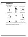
Inspect Shipment
The parts required to assemble and install the reverse osmosis system are included in a parts bag, located inside the shipping carton.
Water supply fitting
Drain adaptor
Hanger washers and screws
RO product water faucet
(Model WHER12)
Monitor
(Model WHER18)
RO product water faucet
(Model WHER18)
Teflon tape
Tank valve
“AA” batteries
(Model WHER18)
Check the reverse osmosis system for possible shipping damage and parts loss. Also inspect and note
any damage to the shipping carton.
Remove and discard (or recycle) all packing materials. To avoid loss of small parts, we suggest you
keep the small parts in the parts bag until you are ready to use them.
4
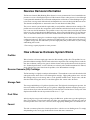
Reverse Osmosis Information
The Reverse Osmosis (RO) Drinking Water System is a water treatment unit. It uses household water
pressure to reverse a natural physical process called osmosis. Water, under pressure, is forced through
a semi-permeable membrane where minerals and impurities are filtered out. Clean drinking water goes
to the faucet or storage tank, while minerals and impurities are sent to the drain with RO waste water.
The minerals and impurities are measured in water as total dissolved solids (TDS).
The reverse osmosis system includes replaceable pre and postfilter sediment-carbon cartridges. The
prefilter removes sand, silt, dirt, rust particles, other sediments, and chlorine from the water supply before it can enter the RO membrane. The postfilter removes any tastes and/or odors that may remain
in the water, after passing through the RO membrane, before going to the RO faucet. To prevent water
waste, an automatic shutoff valve closes when the RO faucet is closed and the storage tank is full.
The reverse osmosis system gives a continuous supply of sparkling clear, delicious water for drinking,
cooking and other uses. The reverse osmosis process makes water very slowly, that is why there is a
2.3 gallon* storage tank. This will enable you to have high quality R.O. product water for your cooking
and drinking water needs.
* Exact storage capacity depends on water pressure.
How a Reverse Osmosis System Works
Prefilter
Water from the cold water supply pipe enters the RO assembly prefilter first. The prefilter has a replaceable sediment cartridge with activated carbon in its composition. The cartridge removes sand, silt,
dirt, other sediments, and up to the ppm of chlorine shown in the specifications from the feed water.
See “Product Specifications” section. Chlorine can adversely effect the RO membrane life. Filtered,
clean, chlorine-- free water flows from the prefilter, to the RO membrane cartridge.
Reverse Osmosis (RO) Cartridge
The RO cartridge is a tightly wound special membrane. The membrane removes the dissolved solids
and organic matter when water is forced through the cartridge. High quality product water exits the
RO cartridge and goes to the storage tank, or to the postfilter and RO faucet. Reject water, with the
dissolved solids and organic matter, is routed through the flow control and to the drain.
Storage Tank
The storage tank holds up to 2.3 gallons of product water. The higher the incoming water pressure, the
more water will be stored in the tank, up to 2.3 gallons. A diaphragm inside the tank keeps water pressurized to about 30 psi, when the tank is full, to provide fast flow to the RO faucet. The dry side of the
diaphram that divides the tank is pressurized with air to 5 - 7 psi.
Post Filter
After leaving the storage tank, but before going to the RO faucet, product water goes through the post
filter. The post filter is an activated carbon type filter. Any remaining tastes and odors are removed
from the product water. Taste-- free, odor-- free, clean, high quality drinking water is available for use.
Faucet
The sink or countertop faucet has a hand operated lever or knob to access drinking water. To comply
with plumbing codes, an air-- gap is built into the faucet drain water connection.
5
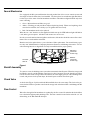
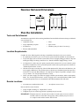
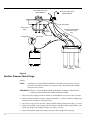
Faucet Electronics
If so equipped, the RO system will monitor the total product flow of the reverse osmosis system and
also length of time the filters have been installed. The faucet base has an indicator light that flashes
to inform you of the status of the RO membrane and filters. This indicator light will flash only when
water is flowing.
S
Green - RO membrane and filters are good.
S
Amber - Warning, pre and post filters will need replacing shortly. Filters need replacing, when
water has been drawn, after 182 days (or 750 gallons have been used).
S
Red - RO membrane needs to be replaced.
When the two “AA” batteries are first applied at initial start up, the LED indicator light will flash in
a red, amber, green sequence. All timers and counters are reset to zero.
In order to reset the monitor time and gallon count feature, the batteries should be removed for a minimum of five seconds and then reinserted.
Batteries need to be replaced once a year at the time of filter replacement. Do not mix battery types,
use only “AA” alkaline batteries. Improper placement of batteries could damage electronics. Use care
when inserting batteries to align them correctly in manifold with the proper polarity.
Electronics
(monitored
models only)
Automatic
Shut Off
Batteries
(monitored
models only)
Figure 1
Shutoff Assembly
To conserve water, the drinking water system has an automatic shutoff system. When the storage tank
has filled to capacity, and the drinking water faucet is closed, pressure closes the shutoff to stop flow
to drain. Pressure in the storage tank is about half of the water supply pressure. After drinking water
is used, and pressure in the system drops, the shutoff opens to allow water flow again.
Check Valve
A check valve (Figure 13) is located in the RO manifold, above the center sump. The check valve prevents a backward flow of product water from the storage tank. A backward flow could damage the RO
membrane.
Flow Control
Water flow through the RO membrane is regulated by the flow control. It maintains the desired flow
rate to obtain the highest quality drinking water. The flow control is located in the end of the 1/4” red
drain tubing, at the RO manifold drain port.
6
Reverse Osmosis Dimensions
15”
13”
STORAGE
TANK
9” dia.
12”
Plan the Installation
Tools and Parts Needed
Assemble the required tools before starting installation. Read and follow the instructions provided with
any tools listed here.
• Adjustable wrench
• Pliers
•
Larger adjustable jaw pliers
•
Pipe wrench
•
Screwdrivers
•
Plumbers putty (for sink, if necessary)
•
Electric drill and drill bit
Location Requirements
Consider all of the following when selecting an installation location for the reverse osmosis.
S For optimum performance your reverse osmosis system should be installed on softened water.
S
To provide supply water to the RO system inlet use the feed supply fitting (provided) or buy and
install pipe fittings for tubing connection. See “Install Cold Water Supply Fitting” section.
S
A refrigerator ice maker may not operate properly when connected to a reverse osmosis system
that has been installed on a water system that operates outside of the specified pressures listed. See
“Product Specifications” section.
S
Chlorine in the water can adversely effect the RO membrane life. Most cities add chlorine to the
water supply to kill bacteria. The prefilter removes chlorine up to the limits shown in the specifications before it enters the RO membrane. It is important to replace the prefilter cartridge at least
every 6 months. See “Product Specifications” section.
S
Check your water supply. The cold water supply to the RO system must be within certain quality
limits. See “Product Specifications” section. If supply water is not within limits, the RO system
can not make product water as it should and reduced RO membrane life will result.
Remote Locations
•
A basement area underneath the sink
•
An adjacent room or closet
Parts needed for remote location:
S
Longer lengths of tubing, see “Repair Parts” section
S
Telephone style wire extension (purchase separtately) may be needed
IMPORTANT: Telephone style wire extension must consist of a male connector on one end and
a female connector on the other to keep proper polarity. Polarity may be reversed
if a coupler is used and the monitor will not work.
7
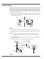
The RO assembly and storage tank is designed for installation under the sink, usually in the kitchen
or bathroom. The RO assembly mounts on a wall surface, or can lay on the cabinet floor next to the
storage tank. Hanger washers and wood screws are included for cabinet wall mounting. The RO product water faucet installs on the sink, or on the countertop next to the sink.
NOTE:
Tubing lengths allow for the removal of the assembly from the hanger washers for
servicing. If tubing lengths are shortened for neater appearance, it may be necessary
to keep the assembly on the hanger washers for service.
RO product
water faucet
(Model WHER12)
RO product
water faucet
(Model WHER18)
cold water
supply
drain adaptor
HOT COLD
Storage
Tank
sink drain
p ---trap
RO Assembly
Figure 2
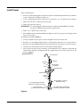
Air Gap Requirements
A suitable drain point is needed for reject water from the RO membrane. A floor drain, laundry tub,
standpipe, sump, etc., is preferred. A sink p-trap drain adaptor is included to install where codes permit,
as an optional drain point. See “Install Drain Adaptor” section.
1---1/2”
airgap
1---1/2”
airgap
1---1/2”
airgap
1---1/2”
airgap
floor drain
8
standpipe
sump
laundry tub
Installation
Install Cold Water Supply Fitting
Check and comply with local plumbing codes as you plan, then install a cold feed (supply) water fitting.
The fitting must provide a leak-- tight connection to the RO 1/4” tubing. A typical connection using the
cold water supply fitting (provided) is shown in Figure 3A. An optional connection, using standard
plumbing fittings (not provided), is shown in Figure 3B.
Cold water supply fitting:
1. Close the house main water shutoff valve, or shutoff valve on cold water line being connected to,
and open faucets to drain water from the sink cold water pipe.
2. Remove nut that connects the cold water faucet to cold water plumbing.
3. Use pipe joint compound or Teflon tape on cold water faucet stud threads and on the male threads
of the water supply fitting that connect to the cold water pipe.
4. Thread water supply fitting onto pipe and reconnect nut to bottom of fitting.
Optional Pipe Fittings (compression type shown):
NOTE:
Be sure to turn off the water supply and open a faucet to drain the pipe.
1. Install a fitting on the kitchen cold water pipe to adapt 1/4” OD tubing. A typical connection is
shown in Figure 3B. If threaded fittings are used, be sure to use pipe joint compound or Teflon tape
on male threads.
A. Water supply connection
(using supplied water supply fitting)
cold water
faucet stud
B.
Water supply typical connection
(using compression fitting)
--- parts not provided ---
water supply fitting
1/4” green tubing
to RO inlet
teflon tape
on threads
cold water
shutoff
cold water
pipe
1/4” compression
fitting
insert
ferrule
cold water
pipe
cold water
shutoff
1/4” tubing
to RO inlet
Figure 3
9
Install Drain Adaptor
Running the drain tubing directly to a floor drain, sump, standpipe, laundry tub is preferred. See “Air
Gap Requirements” section. This can also help eliminate noise in the faucet. However, if that is not
possible or practical, the drain adaptor (provided) installs in the sink drain pipe, always above or ahead
of the p-- trap. The drain adaptor fits 1-1/2” sink drain pipe. Other drain pipe fittings, in addition to the
adaptor, may be needed. Locate so drain tubing from the faucet makes a straight run to the adaptor,
without dips, loops, low spots or kinks.
1. Use a ferrule and nut to assemble the drain tubing connector to the drain adaptor. See Figure 4.
Turn the connector to about 45_ from the 12:00 position, as shown (to 10:00 or 2:00 position as
needed). Tighten the nut securely.
A
B
drain
adaptor
P---trap
P---trap
Figure 4
2. Carefully disassemble the sink drain pipe and clean the tailpiece to assure a leak-tight fit.
3. Install the drain adaptor onto the sink tailpiece, using a ferrule and nut. Snug the nut, but do not
tighten.
NOTE:
If needed, you can cut to shorten the unthreaded end of the adaptor. Do not cut too
short or the adaptor will not make a leak-tight seal with the connecting fitting. See
Figure 5.
4. Assemble the p-- trap to the drain adaptor, and other drain pipe fittings as required (check codes)
to complete the drain run.
5. Tighten all connections, but do not overtighten and break plastic fittings.
sink tailpiece
45_
nut
ferrule
drain adaptor
ferrule
black collet
nut
cut, if needed
drain tubing connector
Figure 5
10
45_
10:00
2:00
Install Faucet
Prepare mounting hole:
1. Select one of the following places for the faucet. Be sure it will fit flat against the surface, and there
is space underneath for tubing (see Figure 9).
S Use an existing sink top hole for a spray hose or other faucet. A 1-- 1/4” diameter hole is needed.
S
Drill a new hole in the countertop next to the sink.
S
Drill a new hole in the sink top.
IMPORTANT: To avoid damaging a sink beyond repair, consult a qualified plumber or installer
for guides to drill holes in porcelain or stainless steel.
2. Drill a 1-- 1/4” diameter hole, if necessary.
3. Place plumbers putty around the drilled hole (Figures 6 and 7) to prevent water leakage around
the base of the faucet.
Assemble faucet (Model WHER12):
1. Loosely assemble the base, spacer, washer and plastic nut onto the faucet stud.
2. Route the 1/4” red tubing through the sink or countertop hole and connect to 1/4” barb on faucet.
3. Route the 3/8” black tubing through sink or the countertop hole and connect to 3/8” barb on faucet.
4. Attach the 3/8” blue tubing to the faucet stud using the tubing adaptor.
5. Lower faucet into place on the countertop, on the underside of the countertop or sink slide the
slotted washer into place and tighten plastic nut. Tighten the nut so the faucet cannot move, but
do not overtighten.
Model WHER12
faucet & spout
1/4” barb
stud
base
3/8” barb
hole in sink or
countertop
plumbers putty
slotted washer
spacer
washer
nut
1/4” red tubing from RO drain
(connect to 1/4” barb on faucet)
3/8” blue tubing
(connect to stud on faucet)
tubing adaptor (connects
to bottom of stud)
3/8” black tubing to drain point
(connect to 3/8” barb on faucet)
Figure 6
11
Assemble Faucet (Model WHER18):
1. Slide the electronics ring onto the faucet stud.
2. Route the 1/4” red tubing through the sink or countertop hole, connect to 1/4” barb on faucet.
3. Route the 3/8” black tubing through the sink or the countertop hole, connect to 3/8” barb on faucet.
4. Lower faucet and electronics ring into place on the countertop. On the underside of the countertop
or sink, loosely assemble the large spacer, small spacer, washer and brass nut onto the faucet stud.
The large spacer can be inverted depending on the thickness of your countertop, if needed.
5. Attach the 3/8” blue tubing to the faucet stud using the tubing adaptor.
6. Route the telephone style wire from the electronics ring through the hole in countertop or sink and
through the slot on the right-- hand side of the RO manifold. This connects to the receptacle on
electronic board located on the RO manifold.
7. Tighten the brass nut. Be sure the telephone style wire is in a position so that it will not be cut,
pinched or kinked before tightening the faucet assembly. Tighten the nut so the faucet cannot
move, but do not overtighten.
Model WHER18
faucet & spout
1/4” barb
stud
hole in sink or
countertop
plumbers putty
3/8” barb
electronics ring
telephone style
wire
large spacer
small spacer
washer
brass nut
1/4” red tubing from RO drain
(connect to 1/4” barb on faucet)
3/8” blue tubing
(connect to stud on faucet)
Figure 7
12
3/8” black tubing to drain point
(connect to 3/8” barb on faucet)
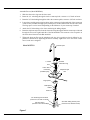
Install RO Assembly
Hang the assembly on the included hanger washers, or lay on the cabinet floor, as desired.
1. Refer to Figure 8 for wall mounting. Hold the assembly up to the wall surface and mark locations
for the hanger washers. Distance needed is 7.2” (approx. 7-7/32”) apart.
2. Install hanger washers at least 15-1/2” up from the cabinet floor, allowing room to remove sumps
from filter heads. Wood screws are provided, or obtain other fasteners as needed.
hanger washer (2)
screw (2)
7.2” (approx. 7---7/32”)
15-1/2” min.
up from floor
Figure 8
Install Storage Tank, Make Remaining Tubing Connections
1. Connect drain tubing, faucet to drain adaptor: Referring to Figure 9, run the loose section of black
3/8” tubing from the faucet to the drain adaptor, with a black collet. Cut this tubing as needed to
route in as straight of a run as possible, without loops, dips, low spots or kinks. Cut the end of the
tubing square. Then push all the way into the fitting. Pull on the tubing to be sure it’s held firmly
in the adaptor fitting. See “Tubing Connection” section.
2. Connect tubing to water supply: Connect the feed (green) tube to the water supply fitting. See
“Tubing Connection” section.
3. Move the storage tank into place next to the RO assembly. You can stand the tank upright, or lay
it on side. Apply no more than two wraps of Teflon tape to the threads on the nipple at the top of
the tank. Hand tighten the tank shutoff valve with the yellow collet onto the tank nipple, then
wrench 1/4 turn only. Be careful not to cross thread.
4. Run the 3/8” yellow tubing to the fitting installed above in step 3. Be sure the end of the tubing
is cut square, and insert all the way into the fitting. Again, pull on the tubing to be sure it’s held
firmly in the fitting.
13
RO product water faucet
(Model WHER12)
RO product water faucet
(Model WHER18)
3/8” black tubing
water supply
fitting
drain
adaptor
HOT COLD
tubing adaptor
telephone style extension
(monitored models
only)
sink p ---trap
yellow collet
Prefilter
RO
Post filter
membrane
Figure 9
Sanitize, Pressure Test & Purge
Sanitize:
NOTE:
Sanitizing is recommended upon installation of the RO system, and after servicing
inner parts. It is important for the service person to have clean hands while handling
inner parts of the system.
IMPORTANT: Be sure to remove the RO membrane and both filter cartridges as follows, before
sanitizing. Chlorine will destroy the RO membrane cartridge.
1. Be sure the water supply to the RO is turned off, and the RO faucet is open to relieve pressure.
2. Remove the RO membrane sump by twisting 1/4 turn left (). Remove the RO cartridge from
sump. Place the cartridge in a clean plastic bag.
3. Be sure the o-ring seal is on the sump. Replace the RO sump by turning to the right () to lock.
4. Remove the postfilter sump, turning to the left. Take the cartridge from the sump and place in the
plastic bag. Replace the sump by turning to the right () to lock.
5. Remove the prefilter sump and cartridge. Also place this cartridge in the clean bag.
14
6. Flush the prefilter sump with fresh water, if needed to clean. Next, fill with water to about 1” from
the top. Add 2 tablespoons of household bleach to water in sump. Do not add chlorine first.
Concentrated, chlorine could attack plastics.
NOTE:
Add bleach to water in sump to avoid plastic damage.
7. Carefully replace the sump in the prefilter location and turn to the right () to lock.
8. Slowly open the water supply to the RO.
9. Open the RO faucet.
10. Allow water to circulate through the RO system until you smell the bleach odor at the faucet. Then
close the faucet and allow the RO to stand idle for 20 minutes.
11. After the 20 minutes open the RO faucet and run water until the bleach odor is gone.
12. Turn off the water supply to the RO.
13. Reinstall the pre filter, post filter and RO cartridge that were removed in steps 1-- 5.
IMPORTANT: Refer to Figure 10, for proper o-- ring orientation, when replacing cartridges.
Leak test:
NOTE:
The sanitizing procedures must be done before leak test.
1. Open the water supply shutoff valve to the RO that was closed during sanitization, step 1.
2. Open the main water supply valve and several house faucets to purge air from the system. Close
faucets when water runs smooth.
3. In about 2 hours, pressure will start to build in the RO system. Then, carefully check all fittings
and connections for water leaks. Correct leaks if any are found.
NOTE:
When the system is first pressurized, water may ‘‘spurt’’ from the faucet airgap hole
in the back of the faucet until air is expelled from the RO system.
Purge RO membrane:
IMPORTANT: The RO cartridge contains a food grade preservative that should be removed
before using water from the system by following the steps below. The
preservative will give product water an unpleasant taste and odor.
NOTE:
Do not remove blue wrapper from R.O. membrane. This will destroy the membrane.
1. Allow the storage tank to fill for about 4 hours. Then open the RO faucet until the tank is empty
and flow stops. Close the RO faucet.
Repeat step 1 to purge the storage tank 6 times. Then the RO system is ready to make product water
for use.
15
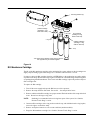
Routine Maintenance
To keep your reverse osmosis system operating and producing high quality water, you must make sure
supply water is always within the limits shown in the specifications. Good supply water helps to assure
longer life from the RO membrane cartridge, prefilter and postfilter cartridges. However, each of these
will wear out in time and need replacement.
This reverse osmosis system contains a replaceable treatment component critical for effective removal of total dissolved solids. The monitor faucet feature provides continuous analysis of the systems performance. For systems not equipped with the monitor faucet function, have your water
tested at least every 6 months to verify your system is performing properly. TDS test kits are available by calling 1-- 800-- 826-- 8553 ext. 47, or check the water testing section of your local phone
directory.
If the RO assembly is wall mounted, you may be able to replace parts with the assembly left on the wall.
If not, simply lift the RO assembly from the mounting washers and lay on the cabinet floor when replacing the prefilter and post filter cartridges and RO membrane.
NOTE:
To prevent spillage, place a container under the RO assembly, or put the RO assembly
in a container to catch the water.
IMPORTANT: Before disconnecting parts, be sure to close the water supply valve to the RO and
close storage tank valve.
Prefilter and Post Filter Cartridges:
Filter life varies depending on local water conditions and the volume of water used. We recommend
you change your filters every 6 months. However, they can be replaced earlier if there is a drop in pressure at the faucet.
To replace the filter cartridges:
1. Turn off the water supply and open the RO faucet to relieve pressure.
2. Remove (turn to the left) both sumps from the filter heads. Be careful . . .the sumps are full of water.
3. Remove and discard the inner cartridges in a proper manner. Flush the insides of the sumps with
fresh water. Do not lose the large o-- ring seals.
4. Insert new cartridges with o-- ring seals towards the top, and with lubricated o-- rings in place, turn
to the right to reattach the sumps.
NOTE:
Use a food grade lubricant such as silicone grease.
5. Remove and replace batteries to reset counter and timer (monitor models).
16
mounting washers (2)
prefilter cartridge
(cartridge o---ring
seals on this end)
RO Cartridge
(cartridge o---ring
seals on this end)
o--ring seal
postfilter cartridge
(cartridge o---ring
seals on this end)
sump
Turn sumps in the direction of the arrow to remove.
Turn opposite way to install and tighten.
Figure 10
RO Membrane Cartridge
The life of the RO membrane cartridge can be maximized by a water softener on the incoming water
supply and performing regular filter changes. See “Prefilters and Post Filters” section.
It’s time to replace the RO cartridge when the red LED flashes or the production rate and/or quality
of product water drops. Product water may begin to taste different or bad, indicating solids and organics
are passing through the RO membrane. To be sure it is the RO cartridge, replace the prefilter and postfilter cartridges first.
To replace the RO cartridge:
1. Turn off the water supply and open the RO faucet to relieve pressure.
2. Remove the sump from the filter head. Be careful . . .the sump is full of water.
3. Remove and discard the RO cartridge in a proper manner. Flush the insides of the sump with fresh
water. Do not lose the large o-- ring seals.
NOTE:
Sanitizing is recommended after servicing inner parts of the system. See “Sanitize,
Pressure Test & Purge” section.
4. Insert new RO cartridges with o-- ring seals towards the top, and with lubricated o-- ring in place,
turn to the right to reattach the sump.
5. Remove and replace batteries to reset counter and timer (monitor models).
6. Purge the RO membrane cartridge. See “Sanitize, Pressure Test & Purge” section.
17
Flow Control
The flow control is vital for proper operation of the RO membrane cartridge. The control keeps water
flow through the membrane at the needed rate to obtain the best quality product water.
Periodically check the flow control to be sure the small hole through it is clean and unrestricted.
o--ring seal
collet
drain port
flow (control)
insert
1/4” tubing
to drain
Figure 11
Tubing Connection (all push---in fitting locations)
This RO system includes push-- in fittings for quick tubing connection. If working with the fittings, do
the following.
Connect Tubing:
1. Use a utility knife to cut the end of tubing square.
2. Inspect the end (about 1”) of the tubing to be sure there are no nicks, scratches or other rough spots.
If needed, cut the tubing again.
3. Push tubing through the collet and all the way into fitting. Full engagement is 11/16” for 1/4”
tubing, and 3/4” for 3/8” tubing.
If using tubing other than tubing supplied with the system, be sure it is of high quality, exact size and
roundness with a smooth surface.
To Disconnect Tubing:
1. Push the collet inward and hold with a finger while pulling the tubing out.
A - Tubing correctly cut and connected
B - Replacing collet and o-ring seal
cut tubing square
collet
Push o-ring seal in to
collet (depress to
bottom of port, then
remove tubing)
follow with collet.
fitting
tubing
end of tubing round and
smooth, with no cuts,
nicks or flat spots
Figure 12
18
11/16” (1/4” tubing)
engagement
3/4” (3/8” tubing)
o--ring seal
collet
Changing Collet and O-- ring:
1. With a small screwdriver remove the collet and o-ring from the fitting. Be careful not to scratch
the internal walls of the collet port.
2. Be sure the port is clean, then lubricate and insert the o-ring seal to the bottom of the port.
3. Push the collet inward until it locks in place.
IMPORTANT: using vinegar or other acid based cleaners on this RO system can degrade some
RO system parts. Use only soap and water for cleaning.
NOTE:
This reverse osmosis system contains a replaceable component critical to the
efficiency of the system. Replacement of the reverse osmosis component should be
with one of identical specifications, as defined by the manufacturer, to assure the
same efficiency and contaminant reduction performance.
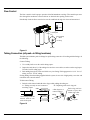
Automatic Shutoff
If the shutoff assembly requires service, be sure to reassemble parts exactly as shown in Figure 13.
Shutoff Assembly
screw (4)
diaphragm
plunger
o-ring
spacer ring
spring
diaphragm
check
valve
ball
Figure 13
19
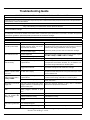
Troubleshooting Guide
REVERSE OSMOSIS SYSTEM CARE GUIDE MODEL NOs. WHER12 and WHER18
1. AT LEAST every 6 months, replace the prefilter and postfilter cartridges or when yellow LED flashes.
2. Replace the RO membrane cartridge when the percent rejection of total dissolved solids (TDS) is less than shown in the specifications
(see B, below) or when red LED flashes.
3. Replace the batteries once per year.
If any of the following occur before the 6 months, replace as directed.
A. Slow Making of Product Water: Replace the prefilter cartridge. If the production rate does not improve, replace the post filter cartridge
and RO membrane cartridge.
B. High Total Dissolved Solids (TDS) in Product Water: Send treated and untreated water samples to a water analysis lab for testing.
It is important to test both the treated and untreated water to determine system performance. If the TDS is not within the system’s
performance guidelines, replace the prefilter, post filter and RO membrane cartridges.
C. Chlorine Taste and/or Odor: Replace the prefilter, post filter and RO membrane cartridges.
OTHER TROUBLESHOOTING
PROBLEM
CAUSE
CORRECTION
Chlorine taste and/or odor The ppm of chlorine in your water supply If the water supply contains more than 2.0 ppm of chlorine, addiin the RO product water
exceeds maximum limits, and has de- tional filtering of the water supply to the RO is needed. Correct this
stroyed the RO membrane.
condition before doing
g maintenance on the RO system.
y
The prefilter is no longer removing chloReplace the prefilter, post filter and RO membrane cartridges.
rine from the water supply.
Other taste and/or odor
Post filter expended.
RO membrane cartridge expended.
Replace
p
the p
post filter cartridge.
g If taste and odor p
persists, replace
p
th prefilter
the
filt cartridge
t id and
d RO membrane
b
cartridge.
t id
Contamination in product water storage. Use sanitizing procedures. Replace the post filter cartridge.
System makes product Water supply to the RO system not with- Check water pressure, if below listed requirement, contact a liwater too slowly
in specifications.
censed plumber. Precondition the water, etc., as needed to conform, before doing maintenance on the RO system.
Prefilter or RO membrane cartridges Replace the prefilter cartridge. If rate does not increase, replace
plugged with sediments.
the postfilter cartridge and RO membrane cartridge.
System delivers lower Storage tank air-charge less than 5 --- 7 Open RO faucet and drain tank until flow slows to a drip. Keep fauamount of product water psi when tank is empty.
cet open and check tank pressure. If low, pressurize to 6 psi. Close
than usual
faucet to refill the tank.
High total dissolved solids Water supply to the RO system not with- Increase water pressure, precondition the water, etc., as needed
product water --- in specifications.
to conform before doing maintenance on the RO system.
((TDS)) in p
fl hi red
flashing
d LED
RO membrane cartridge expended.
Replace the prefilter, postfilter and RO membrane cartridges, flow
control, and screen.
Water leaking from faucet Drain side of faucet airgap (3/8” tubing) Inspect and eliminate restriction or plug. Refer to installation
airgap hole
plugged, restricted, or incorrectly con- instructions for proper drain connection.
nected to drain point.
Continual water flow to Check valve or automatic shutoff as- Clean, repair or replace as needed.
drain
sembly plugged, restricted or parts
worn
Faucet LED indicator light
g
Batteries dead.
Replace with new batteries.
d
does
nott ffunction
ti
after
ft
Batteries installed incorrectly.
Install batteries correctly.
battery change
Static protection device was not dis- Remove batteries for a minimum or one hour and then reinstall.
charged.
Continual water flow to Missing flow restrictor in red drain tube Replace flow restrictor.
drain and no p
product wa- or its corresponding port.
ter
Check ball assembly not seating.
Clean or replace check ball assembly.
NOTE:
20
Sanitizing is recommended after servicing inner parts of the system. See “Sanitize,
Pressure Test and Purge” section.
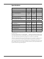
Specifications
Water Specifications
WHER12
WHER18
Metric
Supply water pressure limits
40 --- 100 psi
40 --- 100 psi
280 --- 690 kPa
Supply water temperature limits
40 --- 100 ˚F
40 --- 100 ˚F
5 --- 40˚C
2000 ppm
2000 ppm
---
10 gpg
10 gpg
---
0
0
---
2.0
2.0
---
4 --- 10
4 --- 10
---
Product (quality) water, 24 hours {
14 gallons
22 gallons
53 liters/
83 liters
Product Specifications
WHER12
WHER18
Metric
Percent rejection of TDS, minimum
(new membrane) {
90 --- 95
90 --- 95
---
2.3 gallons
2.3 gallons
8.7 liters
Automatic shutoff control
yes
yes
---
TDS Monitor
no
yes
---
Filter Change Monitor
no
yes
---
Efficiency }
8%
10%
---
Recovery ~
16%
18%
---
Maximum total dissolved solids (TDS)
Maximum water hardness |
Maximum iron, manganese, hydrogen
sulfide
Chlorine in water supply (max. ppm)
Supply water pH limits (pH)
Storage tank capacity (max.)
These systems conform to NSF/ANSI 58 for the specific performance claims as verified and substantiated by test data.
{ feed water supply at 50 psi, 77_F, and 750 TDS - Quality water production, amount of waste
water and percent rejection all vary with changes in pressure, temperature and total dissolved solids.
| For water with hardness greater than 10 grains the use of a softener is recommended.
} Efficiency rating means the percentage of the influent water to the system that is available to the user
as reverse osmosis treated water under operating conditions that approximate typical daily use.
~ Recovery rating means the percentage of the influent water to the membrane portion of the system
that is available to the user as reverse osmosis treated water when the system is operated without a storage tank or when the storage tank is bypassed.
21
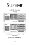
Repair Parts
Manifold Housing
PUSH --- IN FITTINGS
25
| 3/8”
{ 1/4”
24
o--- ring seal
9
collet
10
8
11
7
12
20
6
5
{{
||
4
3
13
21
14
23
o-ring seals
17
22
19
1/4”
Tubing
14
18
15
2
1
16
22
Repair Parts
Key
No.
Part
No.
Key
No.
Part
No.
1
7221128
Sump (3 req.)
16
7205326
Storage Tank
2
7223633
O-- Ring, 2-- 1/4” x 2-- 1/2” (3 req.)
17
7251034
Connector, 1/4 NPT x 3/8 Tube
3
9006062
Screw (2 req.)
18
7208489
Drain Adapter
4
9041700
Hanger Washer (2 req.)
19
7227310
Tee, Feed Adaptor
5
7234210
Paddlewheel & O-- Ring Kit, Model
WHER18 only
20
7273581
Faucet, Model WHER12
6
7234228
Paddlewheel Cover (includes screws),
Model WHER18 only
7263895
Faucet, Model WHER18
21
7235965
Tubing Adaptor, Model WHER12 only
7
7234294
Pwa (includes screw), Model WHER18
only
22
7267124
Spacer, Model WHER18
23
7264841
Rep’l Electronics Ring, Model WHER18
8
7234317
Check Ball Assembly
24
7262564
Cover, order decal below
9
7229451
Screw (4 req.)
7263968
Decal, Cover
10
7229532
Automatic Shut-- off Cover
7209566
Push-in Fitting Kit, 1/4” O
11
7250876
Diaphragm Kit
7209574
Push-in Fitting Kit, 3/8” O
12
7234325
Plunger & Spacer Ring Kit
J
7161823
Tubing, 1/4” x 20’ - white ¡ O
J
7095030
Cone Screen
J
7161784
Tubing, 1/4” x 100’ - white ¡ O
13
7265766
Flow (Control) Insert, Model WHER12
J
7157280
Tubing, 3/8” x 20’ - white ¡ O
7199486
Flow (Control) Insert, Model WHER18
J
7161750
Tubing, 3/8” x 100’ - white ¡ O
14
WHERF
Filter, Carbon Block (2 req.)
15
7264223
RO Membrane Cartridge, Model
WHER12
7266186
RO Membrane Cartridge, Model
WHER18
Description
25
Description
¡ tubing lengths for remote installations, direct replacement for colored lengths of tubing.
Note: This o-ring and collet are for replacement in the manifold housing only. They do not fit the other push-in fittings,
key nos. 17, 18, 20, 21 and 22.
O not included
J not illustrated
To order repair parts call toll free 1-- 866-- 986-- 3223, Monday - Friday, 8 am - 9 pm EST.
Manufactured and warranted by
Ecodyne Water Systems, Inc.
1890 Woodlane Drive
Woodbury, MN 55125
23
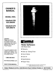
Product Schematic
PRODUCT
WATER
FAUCET
PRODUCT WATER
BLUE
RED
drain flow
control
AUTOMATIC
SHUTOFF
WATER
IN
check
valve
YELLOW
GREEN
air gap
PRODUCT
WATER
STORAGE
gravity
drain
RO
PREFILTER MEMBRANE POSTFILTER
Figure 14
Warranty
ONE YEAR LIMITED WARRANTY ON REVERSE OSMOSIS DRINKING WATER SYSTEM
(except filter cartridges and R. O. membrane)
Warrantor: Ecodyne Water Systems Inc., 1890 Woodlane Drive, Woodbury, MN 55125
Warrantor guarantees, to the original owner, that the Reverse Osmosis Drinking Water System, when installed and maintained in accordance
with the instructions, will be free from defects in materials and workmanship for a period of one year from date of installation.
If, within the first year, a part proves, after inspection, to be defective, Warrantor will, at its sole option, either replace or repair the part without
charge except normal shipping and installation charges. Labor to maintain the equipment is not part of the warranty. Filters and membranes,
which are expendable, are not covered by the warranty.
TO OBTAIN WARRANTY PARTS, SIMPLY CALL 1--866--986--3223, Monday -- Friday, 8 am -- 9 pm EST, for assistance. This warranty
applies only while this product is in use in the United States.
General Provisions
The above warranties are effective provided the Reverse Osmosis Drinking Water System is operated at water pressures not exceeding 100
psi, and at water temperatures not exceeding 100°F; provided further that the Reverse Osmosis Drinking Water System is not subject to abuse,
misuse, alteration, neglect, freezing, accident or negligence; and provided further that the Reverse Osmosis Drinking Water System is not
damaged as the result of any unusual force of nature such as, but not limited to, flood, hurricane, tornado or earthquake.
Warrantor is excused if failure to perform its warranty obligations is the result of strikes, government regulation, materials shortages, or other
circumstances beyond its control.
*THERE ARE NO WARRANTIES ON THE REVERSE OSMOSIS DRINKING WATER SYSTEM BEYOND THOSE SPECIFICALLY
DESCRIBED ABOVE. ALL IMPLIED WARRANTIES, INCLUDING ANY IMPLIED WARRANTY OF MERCHANTABILITY OR
OF FITNESS FOR A PARTICULAR PURPOSE, ARE DISCLAIMED TO THE EXTENT THEY MIGHT EXTEND BEYOND THE
ABOVE PERIODS. THE SOLE OBLIGATION OF WARRANTOR UNDER THESE WARRANTIES IS TO REPLACE OR REPAIR
THE COMPONENT OR PART WHICH PROVES TO BE DEFECTIVE WITHIN THE SPECIFIED TIME PERIOD, AND
WARRANTOR IS NOT LIABLE FOR CONSEQUENTIAL OR INCIDENTAL DAMAGES. NO WARRANTOR DEALER, AGENT,
REPRESENTATIVE, OR OTHER PERSON IS AUTHORIZED TO EXTEND OR EXPAND THE WARRANTIES EXPRESSLY
DESCRIBED ABOVE.
Some states do not allow limitations on how long an implied warranty lasts or exclusions or limitations of incidental or consequential damage,
so the limitations and exclusions in this warranty may not apply to you. This warranty gives you specific legal rights, and you may have other
rights which vary from state to state. This warranty applies to consumer--owned installations only.
R Registered trademark/TM Trademark of Whirlpool, USA, used under license.
E 2004 Whirlpool Corporation. All rights reserved.
24