1
Altivar 32
Variable speed drives for
synchronous and asynchronous motors
Modbus TCP - EtherNet/IP
Communication Manual
S1A28701
03/2010
www.schneider-electric.com
The information provided in this documentation contains general descriptions and/or technical characteristics
of the performance of the products contained herein. This documentation is not intended as a substitute for
and is not to be used for determining suitability or reliability of these products for specific user applications. It
is the duty of any such user or integrator to perform the appropriate and complete risk analysis, evaluation and
testing of the products with respect to the relevant specific application or use thereof. Neither Schneider
Electric nor any of its affiliates or subsidiaries shall be responsible or liable for misuse of the information
contained herein. If you have any suggestions for improvements or amendments or have found errors in this
publication, please notify us.
No part of this document may be reproduced in any form or by any means, electronic or mechanical, including
photocopying, without express written permission of Schneider Electric.
All pertinent state, regional, and local safety regulations must be observed when installing and using this
product. For reasons of safety and to help ensure compliance with documented system data, only the
manufacturer should perform repairs to components.
When devices are used for applications with technical safety requirements, the relevant instructions must be
followed.
Failure to use Schneider Electric software or approved software with our hardware products may result in
injury, harm, or improper operating results.
Failure to observe this information can result in injury or equipment damage.
© 2010 Schneider Electric. All rights reserved.
2
S1A28701 03/2010
Table of Contents
Table of Contents
Safety Information . . . . . . . . . . . . . . . . . . . . . . . . . . . . . . . . . . . . . . . . . . . . . . . . . . . . 6
About the Book . . . . . . . . . . . . . . . . . . . . . . . . . . . . . . . . . . . . . . . . . . . . . . . . . . . . . . . 7
Chapter 1
Presentation . . . . . . . . . . . . . . . . . . . . . . . . . . . . . . . . . . . . . . . . . . . . . . . . . . . . . . . . . . 9
Overview. . . . . . . . . . . . . . . . . . . . . . . . . . . . . . . . . . . . . . . . . . . . . . . . . . . . . . . . . . . . 10
Transparent Ready . . . . . . . . . . . . . . . . . . . . . . . . . . . . . . . . . . . . . . . . . . . . . . . . . . . . 10
Modbus TCP - EtherNet/IP Communication Card Features Overview . . . . . . . . . . . . . 11
Modbus TCP. . . . . . . . . . . . . . . . . . . . . . . . . . . . . . . . . . . . . . . . . . . . . . . . . . . . . . . . . 11
EtherNet/IP . . . . . . . . . . . . . . . . . . . . . . . . . . . . . . . . . . . . . . . . . . . . . . . . . . . . . . . . . . 12
TCP/IP and Ethernet Features . . . . . . . . . . . . . . . . . . . . . . . . . . . . . . . . . . . . . . . . . . . 12
Webserver . . . . . . . . . . . . . . . . . . . . . . . . . . . . . . . . . . . . . . . . . . . . . . . . . . . . . . . . . . 12
Notation . . . . . . . . . . . . . . . . . . . . . . . . . . . . . . . . . . . . . . . . . . . . . . . . . . . . . . . . . . . . 13
Chapter 2
Hardware Setup . . . . . . . . . . . . . . . . . . . . . . . . . . . . . . . . . . . . . . . . . . . . . . . . . . . . . . 14
Hardware Presentation . . . . . . . . . . . . . . . . . . . . . . . . . . . . . . . . . . . . . . . . . . . . . . . . . 15
Firmware and EDS Version Compatibility. . . . . . . . . . . . . . . . . . . . . . . . . . . . . . . . . . . 15
Installation . . . . . . . . . . . . . . . . . . . . . . . . . . . . . . . . . . . . . . . . . . . . . . . . . . . . . . . . . . 15
Wiring . . . . . . . . . . . . . . . . . . . . . . . . . . . . . . . . . . . . . . . . . . . . . . . . . . . . . . . . . . . . . . 18
Installation Topology. . . . . . . . . . . . . . . . . . . . . . . . . . . . . . . . . . . . . . . . . . . . . . . . . . . 19
LED’s Indicators . . . . . . . . . . . . . . . . . . . . . . . . . . . . . . . . . . . . . . . . . . . . . . . . . . . . . . 20
Chapter 3
Configuration and Parameters . . . . . . . . . . . . . . . . . . . . . . . . . . . . . . . . . . . . . . . . . . 22
Network Settings . . . . . . . . . . . . . . . . . . . . . . . . . . . . . . . . . . . . . . . . . . . . . . . . . . . . . 23
Modbus TCP Settings. . . . . . . . . . . . . . . . . . . . . . . . . . . . . . . . . . . . . . . . . . . . . . . . . . 25
FDR Settings . . . . . . . . . . . . . . . . . . . . . . . . . . . . . . . . . . . . . . . . . . . . . . . . . . . . . . . . 28
EtherNet/IP Settings . . . . . . . . . . . . . . . . . . . . . . . . . . . . . . . . . . . . . . . . . . . . . . . . . . . 29
Monitoring of Communication Channels. . . . . . . . . . . . . . . . . . . . . . . . . . . . . . . . . . . . 30
Chapter 4
Configuration of the Drive Commands Settings . . . . . . . . . . . . . . . . . . . . . . . . . . . . 32
Configuration of the Drive for Operation in I/O Profile . . . . . . . . . . . . . . . . . . . . . . . . . 33
Configuration of the Drive for Operation With CiA402 Profile in Combined Mode . . . . 34
Configuration of the Drive for Operation With CiA402 Profile in Separate Mode . . . . . 34
Chapter 5
Network Layer Supported Functions/Protocols . . . . . . . . . . . . . . . . . . . . . . . . . . . . 35
ARP, ICMP and IP Protocol . . . . . . . . . . . . . . . . . . . . . . . . . . . . . . . . . . . . . . . . . . . . . 35
Chapter 6
Transport Layer Protocols. . . . . . . . . . . . . . . . . . . . . . . . . . . . . . . . . . . . . . . . . . . . . . 37
TCP and UDP Protocol. . . . . . . . . . . . . . . . . . . . . . . . . . . . . . . . . . . . . . . . . . . . . . . . . 37
Chapter 7
Modbus TCP Features . . . . . . . . . . . . . . . . . . . . . . . . . . . . . . . . . . . . . . . . . . . . . . . . . 39
Modbus TCP Frames . . . . . . . . . . . . . . . . . . . . . . . . . . . . . . . . . . . . . . . . . . . . . . . . . . 40
ATV32 and VW3 A3 616: Modbus Servers . . . . . . . . . . . . . . . . . . . . . . . . . . . . . . . . . 40
Supported Modbus Functions. . . . . . . . . . . . . . . . . . . . . . . . . . . . . . . . . . . . . . . . . . . . 41
Application Profile with Modbus TCP . . . . . . . . . . . . . . . . . . . . . . . . . . . . . . . . . . . . . . 42
Configuring Communication Detected Fault Management . . . . . . . . . . . . . . . . . . . . . . 42
Configuring Monitor Parameters. . . . . . . . . . . . . . . . . . . . . . . . . . . . . . . . . . . . . . . . . . 44
Chapter 8
Controlling an ATV32 From Modbus TCP (M340) . . . . . . . . . . . . . . . . . . . . . . . . . . . 45
Description of the Configuration . . . . . . . . . . . . . . . . . . . . . . . . . . . . . . . . . . . . . . . . . . 46
Configuration of the Ethernet Module (NOE 100 or NOE 110). . . . . . . . . . . . . . . . . . . 48
Monitor and Control the Exchanges . . . . . . . . . . . . . . . . . . . . . . . . . . . . . . . . . . . . . . . 51
3
Table of Contents
Modbus Messaging . . . . . . . . . . . . . . . . . . . . . . . . . . . . . . . . . . . . . . . . . . . . . . . . . . . 52
Chapter 9
EtherNet/IP Features . . . . . . . . . . . . . . . . . . . . . . . . . . . . . . . . . . . . . . . . . . . . . . . . . . 53
VW3 A3 616 and EtherNet/IP Overview . . . . . . . . . . . . . . . . . . . . . . . . . . . . . . . . . . . . 54
Cyclical Exchanges (Implicit Exchanges) . . . . . . . . . . . . . . . . . . . . . . . . . . . . . . . . . . . 55
Messaging (Explicit Exchanges). . . . . . . . . . . . . . . . . . . . . . . . . . . . . . . . . . . . . . . . . . 59
Detected Fault Management . . . . . . . . . . . . . . . . . . . . . . . . . . . . . . . . . . . . . . . . . . . . 60
Chapter 10
ATV32 Configuration in ETC100 . . . . . . . . . . . . . . . . . . . . . . . . . . . . . . . . . . . . . . . . . 61
Procedure . . . . . . . . . . . . . . . . . . . . . . . . . . . . . . . . . . . . . . . . . . . . . . . . . . . . . . . . . . . 62
Explicit Messaging . . . . . . . . . . . . . . . . . . . . . . . . . . . . . . . . . . . . . . . . . . . . . . . . . . . . 67
Chapter 11
Profiles . . . . . . . . . . . . . . . . . . . . . . . . . . . . . . . . . . . . . . . . . . . . . . . . . . . . . . . . . . . . . 69
Definition of a Profile . . . . . . . . . . . . . . . . . . . . . . . . . . . . . . . . . . . . . . . . . . . . . . . . . . 70
Functional Profiles Supported by the Altivar 32 . . . . . . . . . . . . . . . . . . . . . . . . . . . . . . 71
Chapter 12
CiA®402 - IEC61800-7 Functional Profile . . . . . . . . . . . . . . . . . . . . . . . . . . . . . . . . . . 72
Functional Description . . . . . . . . . . . . . . . . . . . . . . . . . . . . . . . . . . . . . . . . . . . . . . . . . 73
CiA402 State Chart . . . . . . . . . . . . . . . . . . . . . . . . . . . . . . . . . . . . . . . . . . . . . . . . . . . 74
Description of States . . . . . . . . . . . . . . . . . . . . . . . . . . . . . . . . . . . . . . . . . . . . . . . . . . 75
Summary . . . . . . . . . . . . . . . . . . . . . . . . . . . . . . . . . . . . . . . . . . . . . . . . . . . . . . . . . . . 76
Control Word (CMd) . . . . . . . . . . . . . . . . . . . . . . . . . . . . . . . . . . . . . . . . . . . . . . . . . . . 77
Stop Commands . . . . . . . . . . . . . . . . . . . . . . . . . . . . . . . . . . . . . . . . . . . . . . . . . . . . . . 78
Assigning Control Word Bits . . . . . . . . . . . . . . . . . . . . . . . . . . . . . . . . . . . . . . . . . . . . . 78
Status Word (EtA). . . . . . . . . . . . . . . . . . . . . . . . . . . . . . . . . . . . . . . . . . . . . . . . . . . . . 79
Starting Sequence . . . . . . . . . . . . . . . . . . . . . . . . . . . . . . . . . . . . . . . . . . . . . . . . . . . . 80
Sequence for a Drive Powered by the Power Section Line Supply . . . . . . . . . . . . . . . 81
Sequence for a Drive With Separate Control Section . . . . . . . . . . . . . . . . . . . . . . . . . 83
Sequence for a Drive With Line Contactor Control. . . . . . . . . . . . . . . . . . . . . . . . . . . . 86
Chapter 13
CIP Objects Overview . . . . . . . . . . . . . . . . . . . . . . . . . . . . . . . . . . . . . . . . . . . . . . . . . 88
Objects in the AC/DC Drive Device . . . . . . . . . . . . . . . . . . . . . . . . . . . . . . . . . . . . . . . 89
Object 28hex (Motor Data) . . . . . . . . . . . . . . . . . . . . . . . . . . . . . . . . . . . . . . . . . . . . . . 89
Object 29hex (Control Supervisor) . . . . . . . . . . . . . . . . . . . . . . . . . . . . . . . . . . . . . . . . 90
Object 2Ahex (AC/DC Drive) . . . . . . . . . . . . . . . . . . . . . . . . . . . . . . . . . . . . . . . . . . . . 91
Chapter 14
Transparent Ready Features . . . . . . . . . . . . . . . . . . . . . . . . . . . . . . . . . . . . . . . . . . . . 92
Presentation . . . . . . . . . . . . . . . . . . . . . . . . . . . . . . . . . . . . . . . . . . . . . . . . . . . . . . . . . 93
Startup Detailed Behavior. . . . . . . . . . . . . . . . . . . . . . . . . . . . . . . . . . . . . . . . . . . . . . . 94
FDR Operation Behavior . . . . . . . . . . . . . . . . . . . . . . . . . . . . . . . . . . . . . . . . . . . . . . . 95
FDR Settings . . . . . . . . . . . . . . . . . . . . . . . . . . . . . . . . . . . . . . . . . . . . . . . . . . . . . . . . 96
Local Configuration. . . . . . . . . . . . . . . . . . . . . . . . . . . . . . . . . . . . . . . . . . . . . . . . . . . . 97
Downloaded Configuration . . . . . . . . . . . . . . . . . . . . . . . . . . . . . . . . . . . . . . . . . . . . . . 98
Chapter 15
Embedded Webserver . . . . . . . . . . . . . . . . . . . . . . . . . . . . . . . . . . . . . . . . . . . . . . . . 100
Overview. . . . . . . . . . . . . . . . . . . . . . . . . . . . . . . . . . . . . . . . . . . . . . . . . . . . . . . . . . . 101
Connexion to the Webserver . . . . . . . . . . . . . . . . . . . . . . . . . . . . . . . . . . . . . . . . . . . 101
Pages Description . . . . . . . . . . . . . . . . . . . . . . . . . . . . . . . . . . . . . . . . . . . . . . . . . . . 102
FTP Server . . . . . . . . . . . . . . . . . . . . . . . . . . . . . . . . . . . . . . . . . . . . . . . . . . . . . . . . . 111
Chapter 16
Integration in the EtherNet/IP Network . . . . . . . . . . . . . . . . . . . . . . . . . . . . . . . . . . . 112
Installing the EDS File . . . . . . . . . . . . . . . . . . . . . . . . . . . . . . . . . . . . . . . . . . . . . . . . 113
Configuration of the EtherNet/IP Module in the Rockwell PLC. . . . . . . . . . . . . . . . . . 115
Configuring the Implicit Exchanges . . . . . . . . . . . . . . . . . . . . . . . . . . . . . . . . . . . . . . 116
Configuration of the Communication Scanner . . . . . . . . . . . . . . . . . . . . . . . . . . . . . . 118
Configuration of the Communication Period . . . . . . . . . . . . . . . . . . . . . . . . . . . . . . . . 119
Explicit Messaging . . . . . . . . . . . . . . . . . . . . . . . . . . . . . . . . . . . . . . . . . . . . . . . . . . . 120
Assembly Selection . . . . . . . . . . . . . . . . . . . . . . . . . . . . . . . . . . . . . . . . . . . . . . . . . . 122
Chapter 17
CIP Objects . . . . . . . . . . . . . . . . . . . . . . . . . . . . . . . . . . . . . . . . . . . . . . . . . . . . . . . . . 123
Supported Object Classes . . . . . . . . . . . . . . . . . . . . . . . . . . . . . . . . . . . . . . . . . . . . . 124
4
Table of Contents
Identity Object (F1h) . . . . . . . . . . . . . . . . . . . . . . . . . . . . . . . . . . . . . . . . . . . . . . . . . .
Message Router Object (F2h) . . . . . . . . . . . . . . . . . . . . . . . . . . . . . . . . . . . . . . . . . .
TCP/IP Interface Object (F5h) . . . . . . . . . . . . . . . . . . . . . . . . . . . . . . . . . . . . . . . . . .
Ethernet Link Object (F6h) . . . . . . . . . . . . . . . . . . . . . . . . . . . . . . . . . . . . . . . . . . . . .
Assembly Object (04 hex) . . . . . . . . . . . . . . . . . . . . . . . . . . . . . . . . . . . . . . . . . . . . .
Connection Manager Object (06h) . . . . . . . . . . . . . . . . . . . . . . . . . . . . . . . . . . . . . . .
Motor Data Object (28h) . . . . . . . . . . . . . . . . . . . . . . . . . . . . . . . . . . . . . . . . . . . . . . .
Control Supervisor Object (29h) . . . . . . . . . . . . . . . . . . . . . . . . . . . . . . . . . . . . . . . . .
AC/DC Drive Object (2Ah) . . . . . . . . . . . . . . . . . . . . . . . . . . . . . . . . . . . . . . . . . . . . .
Application Object (70h to C7h) / Explicit Messaging . . . . . . . . . . . . . . . . . . . . . . . . .
124
127
127
130
131
133
135
136
137
140
5
Safety Information
Safety Information
§
Important Information
NOTICE
Read these instructions carefully, and look at the equipment to become familiar with the device before trying
to install, operate, or maintain it. The following special messages may appear throughout this documentation
or on the equipment to warn of potential hazards or to call attention to information that clarifies or simplifies a
procedure.
The addition of this symbol to a Danger or Warning safety label indicates that an electrical hazard
exists, which will result in personal injury if the instructions are not followed.
The addition of this symbol to a Danger or Warning safety label indicates that an electrical hazard
exists, which will result in personal injury if the instructions are not followed.
DANGER
DANGER indicates an imminently hazardous situation, which, if not avoided, will result in death or serious
injury.
WARNING
WARNING indicates a potentially hazardous situation, which, if not avoided, can result in death, serious
injury or equipment damage.
CAUTION
CAUTION indicates a potentially hazardous situation, which, if not avoided, can result in injury or equipment
damage.
CAUTION
CAUTION, used without the safety alert symbol, indicates a potentially hazardous situation which, if not
avoided, can result in equipment damage.
PLEASE NOTE
The word “drive” as used in this manual refers to the controller portion of the adjustable speed drive as defined
by NEC.
Electrical equipment should be installed, operated, serviced, and maintained only by qualified personnel. No
responsibility is assumed by Schneider Electric for any consequences arising out of the use of this material.
6
S1A28701 03/2010
About the Book
About the Book
At a Glance
Document Scope
The purpose of this document is to:
• show you how to install the Ethernet fieldbus on your Altivar 32,
• show you how to configure the Altivar 32 to use Ethernet for monitoring and control,
• provide examples of setup using SoMachine and Unity.
NOTE: Read and understand this document and all related documents (see below) before installing,
operating, or maintaining your ATV32.
Validity Note
This documentation is valid for the Altivar 32 Ethernet fieldbus.
Related Documents
Title of Documentation
Reference Number
ATV32 Quick Start
S1A41715
ATV32 Installation manual
S1A28686
ATV32 Programming manual
S1A28692
ATV32 Modbus manual
S1A28698
ATV32 CANopen® manual
S1A28699
ATV32 Communication parameters
S1A44568
ATV32 Atex manual
S1A45605
ATV32 Safety manual
S1A45606
ATV32 other option manuals: see www.schneider-electric.com
You can download the latest versions of these technical publications and other technical information from our
website at www.schneider-electric.com.
Product Related Information
DANGER
UNINTENDED EQUIPMENT OPERATION
• Read and understand this manual before installing or operating the Altivar 32 drive.
• Any changes made to the parameter settings must be performed by qualified personnel..
Failure to follow these instructions will result in death or serious injury.
S1A28701 03/2010
7
About the Book
DANGER
HAZARD OF ELECTRIC SHOCK, EXPLOSION OR ARC FLASH
• Read and understand this manual before installing or operating the Altivar 32 drive. Installation,
adjustment, repair, and maintenance must be performed by qualified personnel.
• The user is responsible for compliance with all international and national electrical code requirements with
respect to grounding of all equipment.
• Many parts of this drive, including the printed circuit boards, operate at the line voltage. DO NOT TOUCH.
Use only electrically insulated tools.
• DO NOT touch unshielded components or terminal strip screw connections with voltage present.
• DO NOT short across terminals PA/+ and PC/– or across the DC bus capacitors.
• Before servicing the drive:
•
- Disconnect all power, including external control power that may be present.
- Place a “DO NOT TURN ON” label on all power disconnects.
- Lock all power disconnects in the open position.
- WAIT 15 MINUTES to allow the DC bus capacitors to discharge.
- Measure the voltage of the DC bus between the PA/+ and PC/– terminals to ensure that the voltage is
less than 42 Vdc.
- If the DC bus capacitors do not discharge completely, contact your local Schneider Electric
representative. Do not repair or operate the drive
Install and close all covers before applying power or starting and stopping the drive.
Failure to follow these instructions will result in death or serious injury.
WARNING
DAMAGE DRIVE EQUIPMENT
Do not operate or install any drive or drive accessory that appears damaged.
Failure to follow these instructions can result in death, serious injury, or equipment damage.
WARNING
LOSS OF CONTROL
• The designer of any control scheme must
- consider the potential failure modes of control paths and,
- for certain critical control functions, provide a means to achieve a safe state during and after a path
failure.
Examples of critical control functions are emergency stop and overtravel stop.
• Separate or redundant control paths must be provided for critical control functions.
• System control paths may include communication links. Consideration must be given to the implications
of unanticipated transmission delays or failures of the link.(1)
Failure to follow these instructions can result in death, serious injury, or equipment damage.
(1) For additional information, refer to NEMA ICS 1.1 (latest edition), “Safety Guidelines for the Application, Installation, and
Maintenance of Solid State Control” and to NEMA ICS 7.1 (latest edition), “Safety Standards for Construction and Guide
for Selection, Installation and Operation of Adjustable-Speed Drive Systems.”
8
S1A28701 03/2010
Presentation
Presentation
1
What's in this Chapter?
This chapter contains the following topics:
Topic
S1A28701 03/2010
Page
Overview
10
Transparent Ready
10
Modbus TCP - EtherNet/IP Communication Card Features Overview
11
Modbus TCP
11
EtherNet/IP
12
TCP/IP and Ethernet Features
12
Webserver
12
Notation
13
9
Presentation
Overview
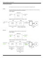
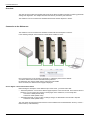
The VW3 A3 616 is a dual port Ethernet communication module that can be used in the following two industrial
communication protocols: Modbus TCP and EtherNet/IP. In addition of the communication services provided
by each protocol, the VW3 A3 616 provides a set of common services at the Ethernet and TCP/IP level. The
VW3 A3 616 offers also an embedded web server (English) which offers comfortable monitoring and
commissioning functions directly from a standard web browser.
Basic Overview According to the Simplified TCP/IP Model
Application
Modbus TCP - EtherNet/IP
Transport
TCP / UDP
Network
IP
Link
Ethernet
Transparent Ready
Introduced by Schneider Electric, the Transparent Ready concept enables transparent communication
between control system devices, production and management. Network technologies and the associated new
services are used to share and distribute data between sensors, PLCs, workstations and third-party devices
in an increasingly efficient manner. Web servers embedded in the network components and control system
devices can be used to:
• Access configuration data transparently
• Perform remote diagnostics
• Incorporate simple human/machine interface functions
This concept is based on the Ethernet TCP/IP industrial standard which proposes a single network that meets
most communication requirements from sensors/actuators to production management systems. Where a
variety of communication systems is usually required, Transparent Ready standard technologies can result in
significant cost savings in the areas of definition, installation, maintenance or training.
10
S1A28701 03/2010
Presentation
Transparent Ready is based on:
• Ethernet TCP/IP-based services meeting control system requirements in terms of functions, performance
and quality of services
• Products including several ranges of PLC, distributed I/O, industrial terminals, variable speed drives,
gateways and an increasing number of partner products
• The ConneXium range of cabling accessories: hubs, switches, cables adapted to the environment and to
the requirements of industrial conditions.
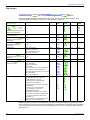
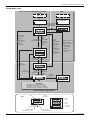
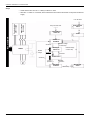
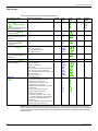
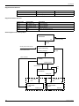
Modbus TCP - EtherNet/IP Communication Card Features Overview
EtherNet/IP
Controller
IO
Scanner
Modbus TCP
Controller
IO
Scanner
EtherNet/IP cyclic
exchanges
EtherNet/IP
messaging
I/O scanner
Modbus TCP
Assemblies
20 - 70
21 - 71
CIP drive
profiles
100 - 101
IO
Scanner
(func 23)
Modbus
Messaging
(func: 3, 6, 16,
23, 43)
CiA402 native
drive profile +
4RW configurable
parameters
Parameters
management
CIP
Explicit
messaging
Faulty Device
replacement
Standard
Web
browser
IE, Mozilla
Embedded
Web server,
Java applets
Drive setup
Modbus TCP
The Modbus application layer is standard. Thousands of manufacturers are already implementing this
protocol. Many have already developed a Modbus TCP/IP connection and numerous products are currently
available. With the simplicity of its protocol and the fast Ethernet throughput data rate of 100 Mbps, Modbus
TCP/IP achieves excellent performance.
S1A28701 03/2010
11
Presentation
EtherNet/IP
EtherNet/IP is a fieldbus based on TCP and UDP. EtherNet/IP extends Ethernet by an advanced industrial
protocol (CIP, Common Industrial Protocol) as an application layer for automation applications in this way,
Ethernet is excellently suited for industrial control. Products from different manufacturers can be networked
without the need for special interface adaptation.
TCP/IP and Ethernet Features
The product supports the following functions via:
• Automatic IP address assignment via BOOTP or DHCP
• Automatic configuration data via FDR (only in Modbus TCP)
• Commissioning via commissioning software SoMove
• Diagnostics and configuration via integrated web server
Webserver
The standard Web server (English only) provides access to the following pages:
• Altivar Viewer
• Data Viewer
• Ethernet
• Security
• Etc...
12
S1A28701 03/2010
Presentation
Notation
Drive Terminal Displays
The graphic display terminal (to be ordered separately - reference VW3 A1 101) menus are shown in square
brackets.
Example: [COMMUNICATION]
The integrated 7-segment display terminal menus are shown in round brackets.
Example: (COM-)
Parameter names are displayed on the graphic display terminal in square brackets.
Example: [Fallback speed]
Parameter codes are displayed on the integrated 7-segment display terminal in round brackets.
Example: (LFF)
Formats
In this manual, hexadecimal values are written as follows: 16#
Binary values are written as follows: 2#
Abbreviations
Req. = Required
Opt. = Optional
S1A28701 03/2010
13
Hardware Setup
Hardware Setup
2
What's in this Chapter?
This chapter contains the following topics:
Topic
14
Page
Hardware Presentation
15
Firmware and EDS Version Compatibility
15
Installation
15
Wiring
18
Installation Topology
19
LED’s Indicators
20
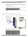
Hardware Setup
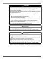
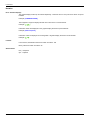
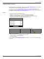
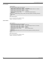
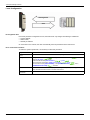
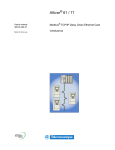
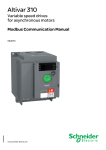
Hardware Presentation
The following figure presents the Modbus TCP - EtherNet/IP module:
Firmware and EDS Version Compatibility
Only VW3 A3 616 option cards, with minimum 1.2IE01 firmware version, are compliant with ATV32.
NOTE: Check the firmware version, on the packaging label (on the right part of the label).
The associated EDS is the following SE_ET_ATV32_0102E.eds. This file is available on
www.schneider-electric.com.
Installation
Check that the card catalog number marked on the label is the same as that on the delivery note corresponding
to the purchase order.
Remove the communication module from its packaging and check that it has not been damaged in transit.
CAUTION
RISK OF DAMAGE TO THE DRIVE
Install only communication modules designed for ATV32. See references in the catalog.
Failure to follow these instructions can result in equipment damage.
DANGER
HAZARD OF ELECTRIC SHOCK, EXPLOSION OR ARC FLASH
Read and understand the precautions in “About the Book” on page 7 before performing the procedure in this
section.
Failure to follow these instructions will result in death or serious injury.
15
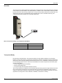
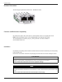
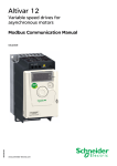
Hardware Setup
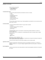
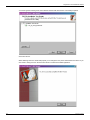
Install the Modbus TCP - EtherNet/IP module in ATV32 as follows:
16
Step
Action
1
Ensure that the power is off.
Locate the option card port on the
bottom of the ATV32.
2
Extract the cover.
3
Insert the VW3 A3 616 module.
4
Check that the module is correctly
inserted and locked mechanically in
the drive.
Comment
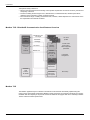
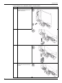
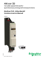
Hardware Setup
Extract the communication module as follows:
Step
Action
1
Ensure that the power is off.
Press the strip.
2
Extract the module while maintaining
the strip pressed.
Comment
17
Hardware Setup
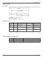
Wiring
The VW3 A3 616 option card is equipped with 2 RJ45 female sockets for the Ethernet connection.
• Use equipotential bonding conductors,
• Use pre-assembled cables to reduce the wiring mistakes,
• Verify that wiring, cables and connected interfaces meet the PELV requirements.
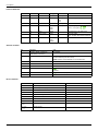
The following table describes the pin out of each RJ45:
18
Pin
Signal
Meaning
1
Tx+
Ethernet transmit line +
2
Tx-
Ethernet transmit line -
3
Rx+
Ethernet receive line +
4
-
-
5
-
-
6
Rx-
Ethernet receive line -
7
-
-
8
-
-
Hardware Setup
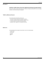
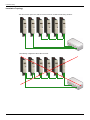
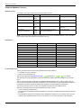
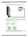
Installation Topology
The VW3 A3 616 option card, with its 2 RJ45 connector, enables several wiring solutions:
The following configuration MUST NOT be used:
19
Hardware Setup
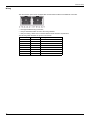
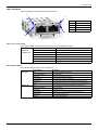
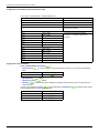
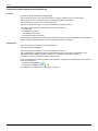
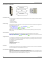
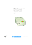
LED’s Indicators
The following figures describes the LEDs status module:
2
3
LED
Description
LNK (1)
Connection A port
MS (2)
Module status
NS (3)
Network status
LNK (4)
Connection B port
4
1
LEDs 1 and 4: Link Activity
These LEDs indicate the status of the Ethernet port A (1) and Ethernet port B (4):
EtherNet/IP
& Modbus TCP
Color & Status
Description
OFF
No link
Flashing Green/Yellow
Power up testing
Green ON
Link at 100Mbps
Yellow ON
Link at 10 Mbps
Green Blink
Activity at 100 Mbps
Yellow Blink
Activity at 10 Mbps
LED 2: Module Status
This LED indicates the status of the module status:
EtherNet/IP
Modbus TCP
20
Color & Status
Description
OFF
No power is supplied to the device
Flashing Green/Red
Power up testing
Green ON
The device is operating correctly.
Green flashing
The device has not been configured
Red flashing
The device has detected a recoverable minor detected fault
Red on
The device has detected a non-recoverable major detected fault
OFF
The device does not have an IP address or powered off
Flashing Green/Red
Power up testing
Green ON
The device is ready
Green flashing
The device is not ready (waiting for cable connection,...)
Red flashing
The device has detected a (CnF)
Red ON
The device has detected a (ILF)
Hardware Setup
LED 3: Network Status
This LED indicates the status of the module status:
Color & Status
EtherNet/IP
Modbus TCP
Description
OFF
The device does not have an IP address or powered off
Flashing Green/Red
Power up testing
Green ON
The device has at least one established connection
Green flashing
The device has no at least one established connection
Red flashing
One or more of the connections in which this device is the
target has timed out. This shall be left only if all time out
connections are reestablished or if the device is reset.
Red on
The device has detected that its IP address is already in use
OFF
The device does not have an IP address or powered off
Flashing Green/Red
Power up testing
Green ON
At least one port is connected and an IP° address has been
obtained
Green flashing 3 times
All ports are unplugged, but the card has an IP address
Green flashing 4 times
Detected error: duplicate IP address
Green flashing 5 times
The card is performing a BOOTP or DHCP sequence
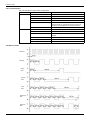
LED Behavior Detail
Flickering
Blinking
Single
flash
Double
flash
Triple
flash
Quadruple
flash
Quintuple
flash
21
Configuration and Parameters
Configuration and Parameters
3
Overview
This chapters describes the parameters of the VW3 A3 616 module. These parameters are described here
according to the local HMI or the Graphic keypad. These settings are also possible from SoMove or from the
embedded web server.
What's in this Chapter?
This chapter contains the following topics:
Topic
22
Page
Network Settings
23
Modbus TCP Settings
25
FDR Settings
28
EtherNet/IP Settings
29
Monitoring of Communication Channels
30
S1A28701 03/2010
Configuration and Parameters
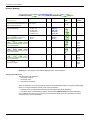
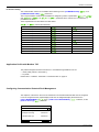
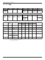
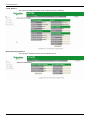
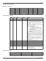
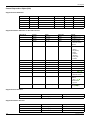
Network Settings
The parameters are accessible via [CONFIGURATION] (COnF-), [FULL] (FULL-),
[COMMUNICATION] (COM-) menu and [COMMUNICATION CARD] (Cbd-) submenu.
Parameter Description
(HMI mnemonic)
Range or Listed Values
Default Long Name
Short
Name
Access
Parameter
Number
[Ethernet protocol] (EthM)
0:Modbus TCP
This parameter defines which protocol is 1:EtherNet/IP
used for implicit exchanges
0
[Modbus TCP]
(MtCP)
(EIP)
R/W
64241
[Rate setting] (rdS)
Rate and data settings
0: Autodetect
1: 10 Mbps Full
2: 10 Mbps Half
3: 100 Mbps Full
4: 100 Mbps Half
Auto
[Auto]
[10M. full]
[10M. half]
[100M. full]
[100M. half]
(AUtO)
(10F)
(10H)
(100F)
(100H)
R/W
64251
[IP mode] (IpM)
Use this parameter to select the IP
address assignment method
0: Man
1: BOOTP
2: DHCP
DHCP
[fixed]
[BOOTP]
[DHCP]
(MAnU)
(bOOt)
(dHCP)
R/W
64250
[IP card] (IPC)
0 to 255 for each 4 fields
(IPC1) (IPC2) (IPC3) (IPC4)
These fields are editable when IP mode
is set to Fixed address
-
[139.160.069.241]
(139)
(160)
(069)
(241)
R/W
64212
64213
64214
64215
[IP Mask] (IPM)
0 to 255 for each 4 fields
(IPM1) (IPM2) (IPM3) (IPM4)
These fields are editable when IP mode
is set to Fixed address
-
[255.255.254.0]
(255)
(255)
(254)
(0)
R/W
64216
64217
64218
64219
0 to 255 for each 4 fields
[IP Gate] (IPG)
(IPG1) (IPG2) (IPG3) (IPG4)
These fields are editable when IP mode
is set to Fixed address
-
[0.0.0.0]
(0)
(0)
(0)
(0)
R/W
64220
64221
64222
64223
[MAC @] (MAC)
MAC address display
-
[00-80-F4-XX-XX-XX] 0080
F4--XX
XXXX
R
64267
64268
64269
[00-80-F4-XX-XX-XX]
NOTE: Before entry begins, the IP address displayed is the active IP address.
Assigning IP Addresses
The drive needs 3 IP addresses:
• The drive IP address.
• The subnet mask.
• The gateway IP address.
These IP addresses can be entered directly: Using the integrated display terminal. Using the graphic display
terminal. Or using the SoMove software. They can be provided by:
• A BOOTP server (correspondence between the MAC address and the IP addresses).
• Or a DHCP server (correspondence between Device Name [DEVICE NAME] and the IP addresses).
If an IP address other than 0.0.0.0 has been entered using the display terminal or the SoMove software,
assignment using a server is disabled.
S1A28701 03/2010
23
Configuration and Parameters
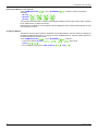
Entering IP Addresses in the Terminal
In the [COMMUNICATION] (COM-) menu, [ETHERNET] (EtH-) submenu, enter the following IP
addresses:
• [IP card] (IPC1) (IPC2) (IPC3) (IPC4),
• [IP Mask] (IPM1) (IPM2) (IPM3) (IPM4),
• [IP Gate] (IPG1) (IPG2) (IPG3) (IPG4).
Turn the drive off and then back on again (control voltage if a separate power supply is being used), otherwise
the IP addresses are not taken into account.
If this address is modified, the new IP address entered is displayed. This IP address will be effective the next
time the drive is turned on.
Configuring BOOTP
The BOOTP service is used to assign IP addresses from the MAC address. The MAC address consisting of 6
hexadecimal digits (00-80-F4-80-xx-yy) must be entered in the BOOTP server. The MAC address appears on
the label attached to the Ethernet card.
In the [COMMUNICATION] (COM-) menu, [ETHERNET] (EtH-) submenu:
• Leave the IP address [IP card] (IPC1) (IPC2) (IPC3) (IPC4) at the value
[0.0.0.0] (0) (0) (0) (0).
• Do not enable the FDR service: [FDR validation] (FdrU) = [No] (nO).
24
S1A28701 03/2010
Configuration and Parameters
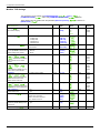
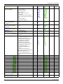
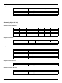
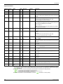
Modbus TCP Settings
The parameters are accessible via [CONFIGURATION] (COnF-), [FULL] (FULL-),
[COMMUNICATION] (COM-) menu and [COMMUNICATION CARD] (Cbd-) submenu.
These settings are only visible when the parameter [Ethernet protocol] (EtHM) is defined on
[ModbusTCP] (MbtP):
Parameter Description
(HMI mnemonic)
Range or Listed Values
Default
Long
Name
Short
Name
Access
Parameter
Number
[MAC @] (MAC)
MAC address display
[00-80-F4-XX-XX-XX]
-
[00-80-F4-XXXX-XX]
0080
F4--XX
XXXX
R
64267
64268
64269
[Rate setting] (rdS)
0: Autodetect
1: 10 Mbps Full
2: 10 Mbps Half
3: 100 Mbps Full
4: 100 Mbps Half
Auto
[Auto]
[10M. full]
[10M. half]
[100M. full]
[100M. half]
(AUtO)
(10F)
(10H)
(100F)
(100H)
R/W
64251
[Ethernet protocol] (EthM)
0:Modbus TCP
1:EtherNet/IP
0
[Modbus TCP]
[EthernetIP]
(MbtP)
(EtIP)
R/W
64241
[IP mode] (IpM)
0: Man
Use this parameter to select the IP 1: BOOTP
address assignment method
2: DHCP
DHCP
[fixed]
[BOOTP]
[DHCP]
(MAnU)
(bOOt)
(dHCP)
R/W
64250
[IP card] (IPC)
0 to 255 for each 4 fields
(IPC1) (IPC2) (IPC3)
(IPC4) These fields are editable
when IP mode is set to Fixed
address
0.0.0.0
[0.0.0.0]
(0)
(0)
(0)
(0)
R/W
64212
64213
64214
64215
[IP Gate] (IPG)
(IPG1) (IPG2) (IPG3)
(IPG4)
These fields are editable when IP
mode is set to Fixed address
0 to 255 for each 4 fields
-
[0.0.0.0]
(0)
(0)
(0)
(0)
R/W
64220
64221
64222
64223
[IP Master] (IPp)
(IPp1) (IPp2) (IPp3)
(IPp4) These fields define the
address of the device which
retains control of the drive
0 to 255 for each 4 fields
0.0.0.0
[0.0.0.0]
(0)
(0)
(0)
(0)
R/W
64234
64235
64236
64237
[IP FDR] (IPF)
0 to 255 for each 4 fields
(IPF1) (IPF2) (IPF3)
(IPF4) These fields displays the
served address of the FDR server
0.0.0.0
[0.0.0.0]
(0)
(0)
(0)
(0)
R/W
64224
64225
64226
64227
[FDR validation] (FdrU)
Enable FDR service
0: no
1: yes
yes
[No]
[Yes]
(nO)
(YES)
R/W
64228
[FDR Action] (FdrA)
IDLE: No command
SAVE: save command
REST: download command
DEL: delete command
IDLE
[IDLE]
[SAVE]
[REST]
[DEL]
(IdLE)
(SAUE)
(rESt)
(dEL)
R/W
64229
[FDR autosave] (FdrS)
Interval for periodic saving of the
FDR service
0: no
1: yes
no
[No]
[Yes]
(nO)
(YES)
R/W
64230
[FDRt. autosave] (Fdrt)
0 to 9999 minutes
0
[0]
(0)
R/W
64231
S1A28701 03/2010
25
Configuration and Parameters
Parameter Description
(HMI mnemonic)
Range or Listed Values
[FDR state] (FdrE)
FDR service status
Default
Long
Name
Short
Name
Access
Parameter
Number
IDLE
- IDLE: idle state
- INIT: initialisation
- CONF: configuration
- RDY: ready
- GET: download the current
configuration
- SET: save the current configuration
- APP: Write the FDR server conf. to the
drive
- OPE: operational
- UCFG: not configured
[IDLE]
[INIT]
[CONF]
[RDY]
[GET]
[SET]
[APP]
[OPE]
[UCFG]
(IdLE)
(INIt)
(CONF)
(rdY)
(GEt)
(SEt)
(APP)
(OPE)
(UCFG)
RW
64232
[FDR file error] (FdrF)
Enable FDR detected fault
management
0: no
1: yes
yes
[No]
[Yes]
(nO)
(YES)
R/W
64240
[Ethernet local conf] (LCFG)
Selection of local or server
configuration
0: no
1: yes
no
[No]
[Yes]
(nO)
(YES)
R/W
64238
[Eth IO scan act] (IOSA)
Enable I/O scanner
0: no
1: Yes
-
[No]
[Yes]
(nO)
(YES)
R/W
64239
[SERVICES] (EWE-)
Enable web services
0: No web services
1: Web server enabled
1
-
-
R/W
-
[Ethernet Timeout] (tOUt)
0.5 to 60 s
0: disabled
2.0
[2.0s]
(2.0)
R/W
64211
[FDR Fault] (Fdrd)
0
- 0: No detected fault
- 2: the FDR configuration file is not
compatible with the drive type
- 3: Detected error reading the FDR
configuration file on the server
- 4: Detected error writing the
configuration file to the server
- 7:Time out for receipt of the FDR
configuration file from the server
- 9: duplicated IP address.
- 12:the FDR configuration file is
missing
- 13: the FDR configuration file
deployment on the drive has detected a
fault (local detected error)
- 14: the configuration file delete
request has detected a fault on the FDR
server
[0]
[2]
[3]
[4]
[7]
[9]
[12]
[13]
[14]
(0)
(2)
(3)
(4)
(7)
(9)
(12)
(13)
(14)
R
64233
[Scan.Out1 address] (OCA1)
Eligible modbus address
CM
[OCA1]
(OCA1)
R/W
15421
[Scan.Out2 address] (OCA2)
Eligible modbus address
LFRD
[OCA2]
(OCA2)
R/W
15422
[Scan.Out3 address] (OCA3)
Eligible modbus address
0
[OCA3]
(OCA3)
R/W
15423
[Scan.Out4 address] (OCA4)
Eligible modbus address
0
[OCA4]
(OCA4)
R/W
15424
[Scan.Out5 address] (OCA5)
Eligible modbus address
0
[OCA5]
(OCA5)
R/W
15425
[Scan.Out6 address] (OCA6)
Eligible modbus address
0
[OCA6]
(OCA6)
R/W
15426
[Scan. IN1 address] (OMA1)
Eligible modbus address
ETA
[OMA1]
(OMA1)
R/W
15401
[Scan. IN2 address] (OMA2)
Eligible modbus address
RFRD
[OMA2]
(OMA2)
R/W
15402
[Scan. IN3 address] (OMA3)
Eligible modbus address
0
[OMA3]
(OMA3)
R/W
15403
[Scan. IN4 address] (OMA4)
Eligible modbus address
0
[OMA4]
(OMA4)
R/W
15404
[Scan. IN5 address] (OMA5)
Eligible modbus address
0
[OMA5]
(OMA5)
R/W
15405
[Scan. IN6 address] (OMA6)
Eligible modbus address
0
[OMA6]
(OMA6)
R/W
15406
[Internal link fault 1] (ILF1)
Option card 1 ILF faults
Eligible modbus address
0
[-]
(-)
R/W
7134
[Network fault] (CnF)
Eligible modbus address
Communication option interruption
0
[-]
(-)
R/W
7132
26
S1A28701 03/2010
Configuration and Parameters
• If control has been reserved: only the control word (CMd) written by the master with control will be
accepted via I/O Scanning or via Modbus TCP messaging. Two TCP connections are reserved for this
device. In this way, you avoid other TCP clients using all the available connections (8 maximum) and the
control master therefore no longer being able to access the drive Modbus TCP server.
NOTE: Other parameters written from other IP addresses are accepted (for example, adjustments or writing
a setpoint). When control has been reserved and another device attempts to write the control word (CMd):
- via I/O Scanning: The Modbus TCP connection for this client is immediately reinitialized.
- via Modbus TCP messaging: Control is denied.
• If control has not been reserved ([IP Master] = [0.0.0.0] (0) (0) (0) (0)), control can come from any IP
address.
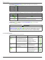
Configuring I/O Scanning
The drive I/O Scanning service can be enabled or disabled in the [COMMUNICATION] (COM-) menu,
[COMMUNICATION CARD] (Cbd-)submenu via parameter [Eth IO scan act] (IOSA).
It is not possible to modify the assignment of the I/O Scanning periodic variables using the display terminal
(integrated or graphic). To configure I/O Scanning, use the standard Web server or the SoMove software.
S1A28701 03/2010
27
Configuration and Parameters
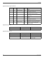
FDR Settings
The parameters are accessible via [CONFIGURATION] (COnF-), [FULL] (FULL-),
[COMMUNICATION] (COM-) menu and [COMMUNICATION CARD] (Cbd-) submenu.
The following table describes the parameters related to the “Fast device replacement settings”. More
information about FDR settings can be found in “FDR Settings” on page 96
Parameter Description
(HMI mnemonic)
Range or Listed Values
Default
Long
Name
Short
Name
Access
Parameter
Number
[IP FDR] (IPF)
(IPF1) (IPF2) (IPF3)
(IPF4)
These fields displays the served
address of the FDR server
0 to 255 for each 4 fields
0.0.0.0
[0.0.0.0]
(0)
(0)
(0)
(0)
R/W
64224
64225
64226
64227
[FDR validation] (FdrU)
Enable FDR service
0: no
1: yes
yes
[No]
[Yes]
(nO)
(YES)
R/W
64228
[Ethernet local conf] (LCFG)
Selection of local or server
configuration
0: no
1: yes
no
[No]
[Yes]
(nO)
(YES)
R/W
64238
[FDR file error] (FdrF)
Enable FDR detected fault
management
0: no
1: yes
yes
[No]
[Yes]
(nO)
(YES)
R/W
64240
[FDR Action] (FdrA)
IDLE: No command
SAVE: save command
REST: download command
DEL: delete command
IDLE
[IDLE]
[SAVE]
[REST]
[DEL]
(IdLE)
(SAUE)
(rESt)
(dEL)
R/W
64229
[FDR autosave] (FdrS)
Interval for periodic saving of the
FDR service
0: no
1: yes
no
[No]
[Yes]
(nO)
(YES)
R/W
64230
0
[FDRt. autosave] (Fdrt)
0 to 9999 minutes
[0]
(0)
R/W
64231
[FDR state] (FdrE)
FDR service status
IDLE
- IDLE: idle state
- INIT: initialisation
- CONF: configuration
- RDY: ready
- GET: download the current configuration
- SET: save the current configuration
- APP: Write the FDR server conf. to the drive
- OPE: operational
- UCFG: not configured
[IDLE]
[INIT]
[CONF]
[RDY]
[GET]
[SET]
[APP]
[OPE]
[UCFG]
(IdLE)
(INIt)
(CONF)
(rdY)
(GEt)
(SEt)
(APP)
(OPE)
(UCFG)
RW
64232
[FDR Fault] (Fdrd)
0
- 0: No detected fault
- 2: the FDR configuration file is not
compatible with the drive type
- 3: Detected error reading the FDR
configuration file on the server
- 4: Detected error writing the configuration
file to the server
- 7:Time out for receipt of the FDR
configuration file from the server
- 9: duplicated IP address.
- 12:the FDR configuration file is missing
- 13: the FDR configuration file deployment
on the drive has detected a fault (local
detected error)
- 14: the configuration file delete request has
detected a fault on the FDR server
[0]
[2]
[3]
[4]
[7]
[9]
[12]
[13]
[14]
(0)
(2)
(3)
(4)
(7)
(9)
(12)
(13)
(14)
R
64233
NOTE: During the application of the configuration, the option use the File Transfer mechanism (FTP) and
some system services. If all the transfers are well finished, the operational state is reached. If the configuration
is ok: the operational state is reached, else if the configuration is not ok: the unconfigured state is reached
(FDR error #14).
28
S1A28701 03/2010
Configuration and Parameters
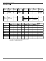
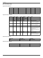
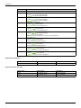
EtherNet/IP Settings
The parameters are accessible via [CONFIGURATION] (COnF-), [FULL] (FULL-),
[COMMUNICATION] (COM-) menu and [COMMUNICATION CARD] (Cbd-) submenu.
These settings are only visible when the parameter [Ethernet protocol] (EtHM) is defined on
[EthernetIP] (EtIP):
Parameter Description
(HMI mnemonic)
Range or Listed Values Default
Long Name
Short
Name
Access
Parameter
Number
[MAC @] (MAC)
MAC address display
[00-80-F4-XX-XX-XX]
-
[00-80-F4-XX-XX-XX]
0080
F4--XX
XXXX
R
64267
64268
64269
[Rate setting] (rdS)
0: Autodetect
1: 10 Mbps Full
2: 10 Mbps Half
3: 100 Mbps Full
4: 100 Mbps Half
Auto
[Auto]
[10M. full]
[10M. half]
[100M. full]
[100M. half]
(AUtO)
(10F)
(10H)
(100F)
(100H)
R/W
64251
[Ethernet protocol] (EthM)
0:Modbus TCP
1:EtherNet/IP
0
[Modbus TCP]
[EthernetIP]
(MbtP)
(EtIP)
R/W
64241
[IP mode] (IpM)
Use this parameter to select the IP
address assignment method
0: Man
1: BOOTP
2: DHCP
DHCP
[fixed]
[BOOTP]
[DHCP]
(MAnU)
(bOOt)
(dHCP)
R/W
64250
[IP card] (IPC)
(IPC1) (IPC2) (IPC3)
(IPC4) These fields are editable
when IP mode is set to Fixed
address
0 to 255 for each 4 fields 0.0.0.0
[0.0.0.0]
(0)
(0)
(0)
(0)
R/W
64212
64213
64214
64215
[IP Gate] (IPG)
(IPG1) (IPG2) (IPG3)
(IPG4)
These fields are editable when IP
mode is set to Fixed address
0 to 255 for each 4 fields -
[0.0.0.0]
(0)
(0)
(0)
(0)
R/W
64220
64221
64222
64223
[Conf. Assembly] (CIO2)
Configured output assembly
20,21,100, 101
20
[20]
-
R
-
[SERVICES] (EWE-)
Enable web services
0: No web services
1: Web server enabled
1
-
-
R/W
-
[Scan.Out1 address] (OCA1)
Eligible modbus address CMD
[OCA1]
(OCA1)
R/W
15421
[Scan.Out2 address] (OCA2)
Eligible modbus address LFRD
[OCA2]
(OCA2)
R/W
15422
[Scan.Out3 address] (OCA3)
Eligible modbus address 0
[OCA3]
(OCA3)
R/W
15423
[Scan.Out4 address] (OCA4)
Eligible modbus address 0
[OCA4]
(OCA4)
R/W
15424
[Scan.Out5 address] (OCA5)
Eligible modbus address 0
[OCA5]
(OCA5)
R/W
15425
[Scan.Out6 address] (OCA6)
Eligible modbus address 0
[OCA6]
(OCA6)
R/W
15426
[Scan. IN1 address] (OMA1)
Eligible modbus address ETA
[OMA1]
(OMA1)
R/W
15401
[Scan. IN2 address] (OMA2)
Eligible modbus address RFRD
[OMA2]
(OMA2)
R/W
15402
[Scan. IN3 address] (OMA3)
Eligible modbus address 0
[OMA3]
(OMA3)
R/W
15403
[Scan. IN4 address] (OMA4)
Eligible modbus address 0
[OMA4]
(OMA4)
R/W
15404
[Scan. IN5 address] (OMA5)
Eligible modbus address 0
[OMA5]
(OMA5)
R/W
15405
[Scan. IN6 address] (OMA6)
Eligible modbus address 0
[OMA6]
(OMA6)
R/W
15406
[Internal link fault 1] (ILF1)
Communication interruption
between option card 1 and drive
Eligible modbus address 0
[-]
(-)
R/W
7134
[Network fault] (CnF)
Communication option detected
fault
Eligible modbus address 0
[-]
(-)
R/W
7132
S1A28701 03/2010
29
Configuration and Parameters
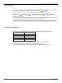
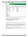
Monitoring of Communication Channels
Command and Reference Channels
All the drive's command and reference parameters are managed on a channel-by-channel basis.
It is possible to identify the last value written for each channel and each command or reference parameter:
Parameter name
Parameter code
Taken into account
by the drive
Control word
Modbus
CANopen
Communication card
(CMd)
(CMd1)
(CMd2)
(CMd3)
Extended control word (CMI)
(CMI1)
(CMI2)
(CMI3)
Speed reference (rpm) (LFrd)
(LFrd1)
(LFrd2)
(LFrd3)
Frequency reference
(0.1 Hz)
(LFr1)
(LFr2)
(LFr3)
(LFr)
PI regulator reference
(PISP)
(PIr1)
(PIr2)
(PIr3)
Analog multiplier
reference
(MFr)
(MFr1)
(MFr2)
(MFr3)
Network Monitoring Criteria
The network is monitored according to the protocol-specific criteria.
Protocol
Criteria
Related detected fault
Integrated Modbus
port
Adjustable time-out for received requests destined for
the drive.
[Modbus fault] (SLF)
Ethernet card
FDR detected fault
IP address duplication detected fault
Adjustable time-out for received control word
(I/O scanning or messaging)
Network overload
[EXTERNAL FAULT COM.] (EPF2)
[NETWORK FAULT] (CNF)
Monitoring of Communication Channels
Communication channels are monitored if they are involved in one of the following parameters:
• The control word ([Cmd value] (CMd)) from the active command channel
• The control word containing the command switch (bit configured on [Cmd switching] (CCS))
• The control word containing the switch for reference 1'1B (bit configured on [Ref 1B switching] (rCb))
• The control word containing the switch for reference 1'2 (bit configured on [Ref. 2 switching] (rFC))
• The frequency or speed reference ([HMI Frequency ref.] (LFr) or LFRD: Nominal speed value) from the
active reference channel
• Summing frequency or speed reference ([HMI Frequency ref.] (LFr) or LFRD: Nominal speed value) 2
(assigned to [Summing ref. 2] (SA2))
• Summing frequency or speed reference ([HMI Frequency ref.] (LFr) or LFRD: Nominal speed value) 3
(assigned to [Summing ref. 3] (SA2))
• Subtracting frequency or speed reference ([HMI Frequency ref.] (LFr) or LFRD: Nominal speed value)
2 (assigned to [Subtract ref. 2] (dA2))
• Subtracting frequency or speed reference ([HMI Frequency ref.] (LFr) or LFRD: Nominal speed value)
3 (assigned to [Subtract ref. 3] (dA3))
• The PID regulator reference (PISP)
• The PID regulator feedback ([AI Virtual 2] (AIU2))
• The reference multiplication coefficient ([Multiplying coeff.] (MFr)) 2 (assigned to
[Multiplier ref. 2] (MA2))
• The reference multiplication coefficient ([Multiplying coeff.] (MFr)) 3 (assigned to
[Multiplier ref. 3] (MA3))
As soon as one of these parameters has been written once to a communication channel, it activates monitoring
for that channel.
If a communication alarm is sent (in accordance with the protocol criteria) by a monitored port or network card,
the drive will trigger a communication interruption.
The drive reacts according to the communication interruption configuration (detected fault, maintenance,
fallback, etc.)
30
S1A28701 03/2010
Configuration and Parameters
If a communication alarm occurs on a channel that is not being monitored, the drive will not trigger a
communication interruption.
Enabling of Communication Channels
A communication channel is enabled once all the parameters involved have been written at least one time.
The drive is only able to start if all channels involved in command and reference are enabled.
Example:
A drive in DSP402 profile is connected to an active communication channel.
It is mandatory to write at least one time the reference and the command in order to switch from “4-Switched
on” to “5-Operation enabled” state
A communication channel is disabled:
• In the event of a communication alarm
• In “forced local“ mode.
Note: On exiting “forced local“ mode:
• The drive copies the run commands, the direction and the forced local reference to the active channel
(maintained).
• Monitoring of the active command and reference channels resumes following a time delay
[Time-out forc. local] (FLOt).
• Drive control only takes effect once the drive has received the reference and the command from the active
channel.
S1A28701 03/2010
31
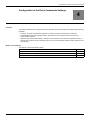
Configuration of the Drive Commands Settings
Configuration of the Drive Commands Settings
4
Overview
This chapter explains how to configure the drive for operation from communication network through 3 following
examples:
• I/O Mode - a simple command Word (based on forward, reverse and reset binary commands).
• Combined Mode (with native profile CiA402) - Both reference and command word come from the
communication network.
• Separate (with native profile CiA402) - Reference and command word come from separate sources: for
example, the command word (in CiA402) comes from the communication network and the reference word
from the HMI.
What's in this Chapter?
This chapter contains the following topics:
Topic
32
Page
Configuration of the Drive for Operation in I/O Profile
33
Configuration of the Drive for Operation With CiA402 Profile in Combined Mode
34
Configuration of the Drive for Operation With CiA402 Profile in Separate Mode
34
S1A28701 03/2010
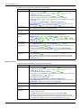
Configuration of the Drive Commands Settings
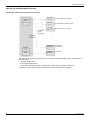
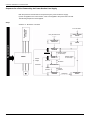
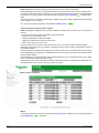
Configuration of the Drive for Operation in I/O Profile
To illustrate the I/O Profile, we will describe a simple example, which can be of course extended with additional
features. The Command word is made of Run forward (bit 0 of CMd), run reverse (bit 1 of CMd), and a
detected fault reset (bit 7 of CMd).
[INPUTS / OUTPUTS CFG] /
[Forward] is assigned to CMD bit 0
[INPUTS / OUTPUTS CFG] /
[Reverse assign.] is assigned to
CMd bit 1
[FAULT MANAGEMENT] /
[FAULT RESET] / [Fault reset] is
assigned to CMd bit 7
Reset
Run reverse
Run forward
The settings will be the following:
[Ref.1 channel] (Fr1)
[HMI] (HMI) (for example)
[RV Inhibition] (rIn)
Default
[Stop Key priority] (PSt)
Default
[Profile] (CHCF)
[I/O profile] (IO)
[Cmd switching] (CCS)
Default
[Cmd channel 1] (Cd1)
[Com. card] (nEt)
The bits of the command word must now be configured.
In the [INPUTS / OUTPUTS CFG] Menu, configure:
[Forward] (Frd)
[Cd00] (Cd00)
[Reverse assign.] (rrS)
[Cd01] (Cd01)
In the [FAULT MANAGEMENT] menu, [FAULT RESET] submenu, configure:
[Fault reset] (rSF)
S1A28701 03/2010
[Cd07] (Cd07)
33
Configuration of the Drive Commands Settings
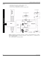
Configuration of the Drive for Operation With CiA402 Profile in Combined Mode
This chapter describes how to configure the settings of the drive if it is controlled in CiA402 Mode. The example
focuses on the Not separate mode (Combined). Additional modes such as the separate Mode are detailed in
the ATV32 Programming manual.
In the Command Menu [Command] (CtL-):
• [Ref.1 channel] (Fr1): is set according to the communication source you can choose in the following
table:
Origin of the control
Ref1 Channel setting
EtherNet/IP - Modbus TCP
[Com. card] (nEt)
• [Profile] (CHCF): defines if the drive operates in combined mode (reference and command from the same
channel).
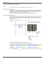
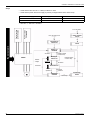
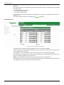
Configuration of the Drive for Operation With CiA402 Profile in Separate Mode
Alternate combinations are possible, see the ATV32 programming manual for the list of possible settings.
Example:
Speed
reference
Control Word
The drive is controlled from the communication (EtherNet) but the reference is adjusted on the local HMI. The
control word comes from the controller and is written according to CiA402 profile.
The settings will be as follows:
34
[Ref.1 channel] (Fr1)
[AI virtual 1] (AIU1)
[RV Inhibition] (rIn)
Default
[Stop Key priority] (PSt)
Default
[Profile] (CHCF)
[Separate] (SEp)
[Cmd switching] (CCS)
Default
[Cmd channel 1] (Cd1)
[Com. card] (nEt)
S1A28701 03/2010
Network Layer Supported Functions/Protocols
Network Layer Supported Functions/Protocols
5
ARP, ICMP and IP Protocol
ARP Protocol
The ARP (Address Resolution Protocol) is a protocol used by the IP (Internet Protocol) network layer protocol
to map IP network addresses to hardware addresses (MAC address). The protocol operates below the
network layer as a part of the OSI link layer, and is used when IP is used over Ethernet.
A host, wishing to obtain a physical address, broadcasts an ARP request onto the TCP/IP network. The host
on the network, that has the IP address in the request, then replies with its physical HA (Hardware Address).
There are four types of ARP messages which may be sent by the ARP protocol. They are identified by two
values in the “operation” field of an ARP message. The types of message are: ARP request; ARP reply.
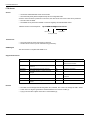
The following table describes the format of an ARP message:
0
8
15 16
31
Hardware Type
HLEN
(Hardware address Length)
Protocol Type
PLEN
(Protocol address Length)
Operation
Sender HA (bytes 0-3)
Sender HA (bytes 4-5)
Sender IP (bytes 0-1)
Sender IP (bytes 2-3)
Target HA (bytes 0-1)
Target HA (bytes 2-5)
Target IP (bytes 0-3)
ARP frames are described as follows:
• ARP Request: it allows to get the hardware (MAC) Address of a remote device.
• Gratuitous ARP: it allows to announce the use of an IP and Hardware Addresses.
• ARP Probe: it allows questioning the network to know if an IP Address is already used without updating the
ARP table of the other hosts on the network.
The following table describes the ARP frames:
ARP Request
S1A28701 03/2010
Gratuitous ARP /
Response
ARP Probe
Sender IP Address
Local IP Address
Local IP Address
Zero
Sender Hardware Address
Local MAC Address
Local MAC Address
Local MAC Address
Target IP Address
Non-zero
(!= Sender IP Address)
Local IP Address
(= Sender IP Address)
IP Address to probe
Target Hardware Address
Zero
Non significant
Zero
35
Network Layer Supported Functions/Protocols
ICMP Protocol
The Option board manages the ICMP protocol.
• ICMP client: not supported
• ICMP server: the managed requests are the following:
Type
Description
Type
Description
0
Echo reply (ping)
11
Time exceeded
3
Destination unreachable
12
Parameter problem
4
Source quench
13
Timestamp request
5
Redirect
14
Timestamp reply
6
Alternate Host Address
15
Information request
8
Echo request (ping)
16
Information reply
9
Router advertisement
17
Address mask request
10
Router solicitation
18
Address mask reply
IP Protocol
The OB (Option Board) implements the IP protocol V4.
SNMP Services
The VW3 A3 316 accepts the Community Name “Schneider” for Reading/Writing and the Community Name
“Public” for Reading only.
MIB
36
Objects
Description
Access
Default Value
SysDescr
Text description of the product
RO
Schneider Electric Altivar Fast
Ethernet TCP/IP Module
SysObjectID
Points in the private MIB on the product RO
reference
1.3.6.1.4.1.3833.1.7.255.6
SysUpTime
Time elapsed since the last power up
Managed by the option
SysContact
Information allowing to contact the node R/W
manager
'' ''
SysName
Node administrative name
R/W
“ATV” or FDR device name if
configured
SysLocation
Physical location of the product
R/W
'' ''
SysService
Indicates the service type offered by the RO
product.
RO
72
S1A28701 03/2010
Transport Layer Protocols
Transport Layer Protocols
6
TCP and UDP Protocol
Connections
The VW3 A3 616 supports maximum 8 concurrent TCP connections.
The VW3 A3 616 device, according to EtherNet/IP specifications, supports:
• 3 concurrent encapsulation sessions,
• 6 concurrent transport class 3 explicit messaging connections,
• more than 1 transport class 3 connection per encapsulation session.
BOOTP and DHCP Protocol
The VW3 A3 616 can use BOOTP and DHCP protocols.
BOOTP & DHCP protocol frames
The following table describes the DHCP frame format:
OP (1byte)
HTYPE (1 byte)
HLEN (1 byte)
HOPS (1 byte)
XID (4 bytes)
SECS (2 bytes)
FLAGS (2 bytes)
CIADDR (4 bytes)
YIADDR (4 bytes)
SIADDR (4 bytes)
GIADDR (4 bytes)
CHADDR (16 bytes)
SNAME (64 bytes)
FILE (128 bytes)
OPTIONS (312 bytes)
The BOOTP frame is the same: only the VW3 A3 616 OP field is different.
S1A28701 03/2010
37
Transport Layer Protocols
DHCP frame fields are described as follows:
Field
Description
op
Message type DHCP Request / DHCP Reply
htype
Address hardware type
hlen
Hardware address length
hops
Used by relay agent
xid
Transaction identifier, random number chosen by the client allowing to associate the request and the
response
secs
Time in seconds since the beginning of the transaction
flags
First bit used for the Broadcast reply flag
ciaddr
Client IP address, only used if the client can respond to ARP request
yiaddr
Client IP address, “your” IP address proposed by the server
siaddr
IP address of the server
giaddr
Gateway IP address, used when a relay agent needs to be crossed
sname
Server Name
file
Location of boot file
options
Optional parameters with DHCP extensions
DHCP messages
The DHCP protocol uses 8 different types of message during the IP assigning process.
The following table describes the 8 messages:
Message
Description
DISCOVER
The client tries to discover the DHCP server using a broadcast
OFFER
The server proposes a configuration
REQUEST
The client chooses a DHCP server and declines other offers
ACK
The chosen server assigns the IP configuration
NAK
The server rejects the client request
DECLINE
The client declines the assigned IP configuration
RELEASE
The client releases Its IP address before the end of the lease
INFORM
The client asks for network information (it already has an IP address)
Operating mode
The choice between DHCP, BOOTP and manual configuration is made through one parameter:
• Manual mode: the VW3 A3 616 uses the address stored in parameter.
• BOOTP: card receives the addresses from BOOTP server.
• DHCP: if the Altivar Device name [XXX] is a valid name, the VW3 A3 616 receives the addresses from the
DHCP server.
38
S1A28701 03/2010
Modbus TCP Features
Modbus TCP Features
7
What's in this Chapter?
This chapter contains the following topics:
Topic
S1A28701 03/2010
Page
Modbus TCP Frames
40
ATV32 and VW3 A3 616: Modbus Servers
40
Supported Modbus Functions
41
Application Profile with Modbus TCP
42
Configuring Communication Detected Fault Management
42
Configuring Monitor Parameters
44
39
Modbus TCP Features
Modbus TCP Frames
TCP Telegrams
Modbus TCP telegrams are not only Modbus standard requests and responses encapsulated in TCP frames.
TCP ADU
Modbus TCP/IP ADU
PDU
(1) TCP header
(2) MBPA: Modbus Application Protocol Header
(3) ADU: Application data Unit
(4) PDU: Protocol data Unit (The Modbus Message itself)
MBAP Header Structure
Fields
Length
Description
Client
Server
Transaction
Identifier
2 Bytes
Identification of a Modbus request / Initialized by the client
response transaction
Recopied by the server
from the received request
Protocol
Identifier
2 Bytes
0= Modbus protocol
Initialized by the client
Recopied by the server
from the received request
Length
2 Bytes
Number of following bytes
Initialized by the client
(request)
Initialized by the server
(response)
Unit
Identifier
1 Byte
Identification of a remote slave
connected on a serial line or on
other buses
Initialized by the client
Recopied by the server
from the received request
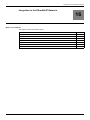
ATV32 and VW3 A3 616: Modbus Servers
40
Unit ID
Modbus TCP server
Accessible parameters
0
Variable speed drive
See ATV32 Communication parameters
251
Ethernet card
See ATV32 Communication parameters
255
I/O scanner
See “I/O Scanner Setting” on page 42
S1A28701 03/2010
Modbus TCP Features
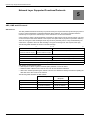
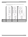
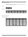
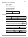
Supported Modbus Functions
Modbus Services
The Modbus TCP option supports the following Modbus services:
Function Name
Code
Description
Remarks
Read holding registers
03
16#03
Read N output words
Max PDU length: 63 words
Write one output word
06
16#06
Write one output word
Write multiple registers
16
16#10
Write N output word
Max PDU length: 63 words
Read/write Multiple registers
23
16#17
Read/write multiple registers
Max PDU length: 20 words (W),
20 words ®
(Sub-function)
Read device Identification
43/14
16#2B
16#OE
Encapsulated interface transport /
Read device identification
See the table below
NOTE: I/O scanner service is based on the function 23. To avoid unpredictable behavior, priority should be
given to this function with regards to the functions 6 and 16.
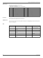
Identification
Id
Value
Comment
16#00
“Schneider electric”
-
16#01
--
-
16#02
“0201”
-
16#04
“ALTIVAR 32”
Drive family
16#05
“ATV-XXXXX”
Drive commercial reference
16#06
“North elevator”
Device Name
16#07
--
-
16#08
2#00000000_00001011
-
16#09
--
-
16#0A
--
-
16#0B
--
-
16#0C
--
-
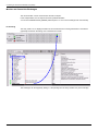
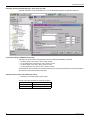
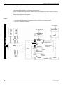
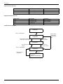
I/O Scanning Service
The I/O scanning service is used to exchange periodic I/O data between:
• A controller or PLC (I/O scanner).
• Devices (I/O scanning servers).
This service is activated with [Eth IO scan act] (IOSA) parameter ((IOSA) = OFF by default).
This exchange is usually performed by implicit services, thus avoiding the need to program the controller
(PLC).
The I/O scanner periodically generates the Read/Write Multiple Registers (23 = 16#17) request. The I/O
scanning service operates if it has been enabled in the PLC and the drive. The drive parameters assigned to
I/O scanning have been selected by default. This assignment can be modified by configuration.
The drive I/O scanning service can also be configured by the Ethernet card Modbus server.
When the I/O scanning service has been enabled in the Altivar 32 drive:
• A TCP connection is assigned to it.
• The parameters assigned in the periodic variables are exchanged cyclically between the Ethernet card and
the drive.
• The parameters assigned to the periodic output variables are reserved for I/O scanning. They cannot be
written by other Modbus services, even if the I/O scanner is not sending its periodic output variables.
S1A28701 03/2010
41
Modbus TCP Features
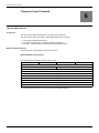
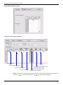
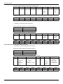
I/O Scanner Setting
The communication scanner is accessible via the following menus: [COMMUNICATION] (COM-) and
[COMMUNICATION CARD] (cbd) submenus.
The 6 output variables and the 6 input variables are assigned by means of parameters (OCA1) to (OCA6)
and (OMA1) to (OMA6). An (OCA x) or (OMA x) parameter with a value of zero is not linked to a
parameter in the drive.
These 6 parameters are described in the table below.
(OCA x) or (OMA x) defines the addresses.
[Scan.Out1 address]
(OCA1)
(CMd)
[Scan.Out2 address]
(OCA2)
(LFrd)
[Scan.Out3 address]
(OCA3)
0
[Scan.Out4 address]
(OCA4)
0
[Scan.Out5 address]
(OCA5)
0
[Scan.Out6 address]
(OCA6)
0
[Scan.IN1 address]
(OMA1)
(EtA)
[Scan.IN2 address]
(OMA2)
(rFrd)
[Scan.IN3 address]
(OMA3)
0
[Scan.IN4 address]
(OMA4)
0
[Scan.IN5 address]
(OMA5)
0
[Scan.IN6 address]
(OMA6)
0
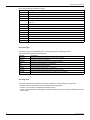
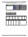
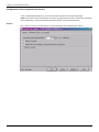
Application Profile with Modbus TCP
The profiles managed with the ATV32 when it is controlled through Modbus TCP are:
• native profile (CiA402 - IEC 61800-7),
• I/O profile.
Please refer to “CiA®402 - IEC61800-7 Functional Profile” on page 72.
Configuring Communication Detected Fault Management
The response of the drive in the event of an Ethernet communication detected fault can be configured.
It can be configured via the graphic display terminal or the integrated display terminal from the
[FAULT MANAGEMENT] (FLt-) menu, [COM. FAULT MANAGEMENT] (CLL-) submenu, via the
[Network fault mgt] (CLL) parameter.
RDY
NET
+0.00Hz
0A
COM. FAULT MANAGEMENT
Network fault mgt
:
Freewheel
CANopen fault mgt
:
Freewheel
Modbus fault mgt
:
Freewheel
Code
42
Quick
S1A28701 03/2010
Modbus TCP Features
The values of the [Network fault mgt] (CLL) parameter, which trigger a drive detected fault
[Com. network] (CnF), are:
Value
Meaning
[Freewheel] (YES)
Freewheel stop (factory setting)
[Ramp stop] (rMP)
Stop on ramp
[Fast stop] (FSt)
Fast stop
[DC injection] (dCI)
DC injection stop
The values of the [Network fault mgt] (CLL) parameter, which do not trigger a drive detected fault, are:
Value
Meaning
[Ignore] (nO)
Detected fault ignored
[Per STT] (Stt)
Stop according to configuration of [Type of stop] (Stt)
[fallback spd] (LFF)
Change to fallback speed, maintained as long as the detected fault persists and the run
command has not been removed
[Spd maint.] (rLS)
The drive maintains the speed at the time the detected fault occurred, as long as the
detected fault persists and the run command has not been removed
The fallback speed can be configured in the [FAULT MANAGEMENT] (FLt-) menu using the
[Fallback speed] (LFF) parameter.
WARNING
LOSS OF CONTROL
If [Network fault mgt] (CLL) = [Ignore] (n0), communication control will be inhibited. For safety reasons,
inhibition of communication fault should only be used for adjustment or special applications purpose.
Failure to follow these instructions can result in death, serious injury, or equipment damage.
CnF and ILF Detected Faults
The following table lists the time-out parameters:
Parameter
Description
Possible Values
Terminal
Display
[Com. network]
(CnF)
(written to the device)
This detected fault is used to indicate that
a network detected fault has occurred.
When the detected fault occurs, the
option position the CNF parameter to the
value corresponding to the detected fault.
When the detected fault has disappeared,
the option writes the CNF parameter to 0
1: Modbus TCP timeout
10: Network overload
11: Loss of carrier
14: Ethernet/IP Scanner timeout
15: Ethernet/IP Idle Poll
16: Ethernet/IP forced EIP trip
17: Application I/O configuration
detected error
[1] (1)
[10] (10)
[11] (11)
[14] (14)
[15] (15)
[16] (16)
[17] (17)
[int. com.link]
(ILF)
This detected fault indicates a critical
13: FDR uncoverable detected error
detected error and can be cleared. It
18: EEPROM detected error
needs a Power Off / Power On to remove 21: Internal detected error
the detected fault
[External fault com.]
(EPF2)
S1A28701 03/2010
8: No valid IP
9: Duplicate IP address
12: FRD unconfigured detected error
13: FDR uncoverable detected error
20: invalid drive config when
activating ODVA profile.
[13] (13)
[18] (18)
[21] (21)
[8] (8)
[9] (9)
[12] (12)
[13] (13)
[20] (20)
43
Modbus TCP Features
Configuring Monitor Parameters
It is possible to select up to 4 parameters to display their values in the [1.2 MONITORING] menu on the graphic
display terminal (to be ordered separately - reference VW3 A1 101).
The selection is made via the [3.3 MONITORING CONFIG.] menu, [CONFIG. COMM. MAP] submenu.
Each parameter, in the range [Address 1 select] ... [Address 4 select], can be used to select the parameter
logic address. An address at zero is used to disable the function.
Example
In the example given here, the monitored words are:
Parameter 1 = Motor current (LCr): logic address 3204, signed decimal format.
Parameter 2 = Motor torque (Otr): logic address 3205, signed decimal format.
Parameter 3 = Last detected fault occurred (LFt): logic address 7121, hexadecimal format.
Disabled parameter: Address W0; default format: Hexadecimal format
•
•
•
•
RDY
NET
+0.00Hz
0A
CONFIG. COMM. MAP.
Address 1 select
:
3204
Format address 1
:
Signed
Address 2 select
:
3205
Format address 2
:
Signed
Address 3 select
:
7121
Code
Quick
One of the three display formats below can be assigned to each monitored word:
Format
Range
Terminal display
Hexadecimal
0000 ... FFFF
[Hex] (HEX)
Signed decimal
-32 767 ... 32 767
[Signed] (SIG)
Unsigned decimal
0 ... 65 535
[Unsigned] (nSG)
NOTE: If a monitored parameter:
• Has been assigned to an unknown address (example: 3200).
• Has been assigned to a protected parameter.
• Has not been assigned.
the value displayed in the [COMMUNICATION MAP] screen will be: “••••” (see “CnF and ILF Detected Faults”
on page 43).
44
S1A28701 03/2010
Controlling an ATV32 From Modbus TCP (M340)
Controlling an ATV32 From Modbus TCP (M340)
8
What's in this Chapter?
This chapter contains the following topics:
Topic
S1A28701 03/2010
Page
Description of the Configuration
46
Configuration of the Ethernet Module (NOE 100 or NOE 110)
48
Monitor and Control the Exchanges
51
Modbus Messaging
52
45
Controlling an ATV32 From Modbus TCP (M340)
Description of the Configuration
The configuration is made of an ATV32 and a M340 with a NOE110 (or NOE100) Ethernet module.
The devices are configured with the (fixed) following IP addresses as follows:
IP: 10.0.0.11
IP: 10.0.0.10
The ATV32 will be controlled through the option communication scanner by means of the I/O scanning service.
It is important to notice that the implicit exchanges are based on the VW3 A3 616 internal communication
scanner and not on the ATV32 internal scanner. The first one is reachable by using the unit ID 255, while the
second one is reachable with the Unit ID 0:
Unit ID: 255
VW3 A3 616
Communication
scanner
Unit ID: 0
ATV32 Internal
Communication
scanner
The option Com scanner parameters start with (OCA x) and (OMA x) and are part of the communication card
submenu (instead of (nCA x), (nMA x) for the drive which are directly located in the Communication main
menu). The usage of the (nCA x), (nMA x) with (via Unit ID 0) is not recommended.
46
S1A28701 03/2010
Controlling an ATV32 From Modbus TCP (M340)
Configuration of the VW3 A3 616 Communication Card
Conf > Full > Communication > Communication card
ETHM = MBTP
Defines the protocol used: Modbus TCP
IPM = MANU
IP address is defined locally
IP card = 10.0.0.11
-
IP Mask 255.0.0.0
-
IP Master = 10.0.0.10
Defines the address of the I/O scanner client
(M340 Ethernet module)
OCA1
8501 > CMD
OCA2
8602 > LFRD
OCA3
-
OCA4
-
OCA5
-
OCA6
-
OMA1
3201 > ETA
OMA2
8604 > RFRD
OMA3
3207 > ULN
OMA4
-
OMA5
-
OMA6
-
In the example we will use the default
parameters + an additional parameter for
monitoring
Configuration of the Command
In the Command Menu [Command] (CtL):
• [Ref1 Channel] (Fr1): is set according to the communication source you can choose in the following
table:
Origin of the control
Ref1 Channel setting
Modbus TCP
[Com. card] (nEt)
• [Rv Inhibition] (rIn): default.
• [Stop Key priority] (PSt): default.
• [Profile] (CHCF): defines if the drives operates in combined mode (reference and command from the
same channel)
For the current example, [Profile] (CHCF) will be adjusted to [Combined] (SIM) as reference and control
are originated from the communication network:
Profile
S1A28701 03/2010
Ref1 Channel setting
CiA402
[Combined] (SIM)
Separate
[Separate] (SEp)
I/O Profile
[I/O Mode] (IO)
47
Controlling an ATV32 From Modbus TCP (M340)
Configuration of the Ethernet Module (NOE 100 or NOE 110)
Create a new logical network in the section:
Configuration of the IP Settings
48
S1A28701 03/2010
Controlling an ATV32 From Modbus TCP (M340)
Enable Messaging With the ATV32
Configure I/O Scanning With the ATV32
ATV IP address
Length: 7
Unit ID: 255 (option card)
Time out for monitoring
Period: here 10 ms
1st address of the %MW for the
read data (ATV > M340)
1st address of the %MW for the
read data (ATV > M340)
NOTE: The length of the communication is 6 words, but the first word of the I/O scanning service is reserved.
In practice, (OMA1) will be linked to %MW101 and (OCA1) will be linked to %MW201.
S1A28701 03/2010
49
Controlling an ATV32 From Modbus TCP (M340)
1st address of the %MW for the written data (M340 > ATV) is shown below:
1st address of the %MW for the
written data (M340 > ATV)
Default values if I/O scanning
is stopped or detect a fault.
1st address of the %MW for the
read data (M340 > ATV)
Length: 7
NOTE: The length of the communication is 6 words, but the first word of the I/O scanning service is reserved.
In practice, (OMA1) will be linked %MW101 and (OCA1) will be linked to %MW201.
Start and Check the Exchanges
Once the project is
built, it can be downloaded to the PLC and then launched. The exchanges (implicit) should start immediately:
50
S1A28701 03/2010
Controlling an ATV32 From Modbus TCP (M340)
Monitor and Control the Exchanges
The communication can be monitored with several I/O objects.
In the example below, the I/O objects have been prefixed EthStatus.
You can check EthStatus.MOD_ERROR (will be equal to 1 if one or more exchanges are unsuccessful).
I/O Scanning
The array %IW0.1.0.1:4 displays the status of the overall active I/O scanning Client/server. This table is
graphically animated in the debug view of the Ethernet module:
The exchanges can be stopped by setting to 1 the pending bit in the array %QW0.1.0.0 (in the example).
S1A28701 03/2010
51
Controlling an ATV32 From Modbus TCP (M340)
Modbus Messaging
Access to the drive parameters is also available by means of the Modbus read / write functions. With the M340,
this feature is achieved with the functions READ_VAR, WRITE_VAR.
Example with READ_VAR:
if not ReadVarbusy then
READ_VAR( ADDM ('0.1.0{10.0.0.11}0'), '%MW' ,3603,2, ReadvarMGT, %MW124:4);
END_If;
READ_VAR address value:
3603
logic address of the 1st read word in the ATV32
2
Numbers of %MW
ReadvarMGT
1st word destination address
%MW124:4
Read_Var request status array
Readvarbusy
bit member of the array %MW124:4
The path to the device is obtained by the ADDM function with the following syntax:
52
0.1.0
Ethernet module
{10.0.0.11}
The IP address of the module
0: UnitID
Drive Unit ID (see “Modbus TCP Features” on page 39 for more details)
S1A28701 03/2010
EtherNet/IP Features
EtherNet/IP Features
9
What's in this Chapter?
This chapter contains the following topics:
Topic
S1A28701 03/2010
Page
VW3 A3 616 and EtherNet/IP Overview
54
Cyclical Exchanges (Implicit Exchanges)
55
Messaging (Explicit Exchanges)
59
Detected Fault Management
60
53
EtherNet/IP Features
VW3 A3 616 and EtherNet/IP Overview
EtherNet/IP Communication Card Features Overview
Master
Controller
I/O Scanner
EtherNet/IP
Cyclic
exchanges
Assemblies
20 - 70
CIP basic speed control profile
Assemblies
21 - 71
CIP extended speed control profile
Assemblies
100 - 101
Native drive profile, I/O profile
EtherNet/IP
messaging
Standard
Web
browser IE,
Mozilla
CIP Explicit
messaging
Parameters
management
Embedded
Web server
Drive setup
The Altivar 32, equipped with the VW3 A3 616, is compliant with the ODVA drive profile. It supports the 3
following profiles:
• CIP basic speed control
• CIP extended speed control
• ATV32 native profile (IEC 61800-7 CiA402) and I/O profile only for assembly 100 and 101.
In addition to these cyclic exchanges, the VW3 A3 616 also supports explicit messaging.
54
S1A28701 03/2010
EtherNet/IP Features
Cyclical Exchanges (Implicit Exchanges)
Overview
This part gives a description of the 3 assembly sets and how to configure them.
Principle of Control configuration
By the configuration of the control, it is possible to decide from what channel the drive receives its commands
and setpoint, either permanently or depending on a switching command. Numerous configurations are
possible. For more information, refer to the Programming manual and Communication parameters manual.
The following configurations are some of the available possibilities.
The selection of the assembly set is made with the EtherNet/IP communication adapter.
Control With Communication Scanner
If the default assemblies (100, 101) are selected, the Altivar 32 will be controlled according to its native profile
CiA402.-IEC-61800-7 (See “CiA®402 - IEC61800-7 Functional Profile” on page 72). By configuring the
communication scanner, it is possible to assign any relevant parameter of the drive to the 6 input and 6 output
variables of the assemblies.
EtherNet/IP
scanner
EtherNet/IP option
Altivar
The mapping of the 100-101 assemblies is
made with the communication scanner
100-101
Native drive profile
CiA402
(OCA1)
(OMA1)
(OCA2)
(OMA2)
(OCA3)
(OMA3)
(OCA4)
(OMA4)
(OCA5)
(OMA5)
(OCA6)
(OMA6)
Assembly
100
Assembly
101
Up to additional
parameters are
mapped
This configuration can be made with:
• HMI
• Keypad
• SoMove
• Webserver
The size of the assembly (100, 101) is fixed and is equal to 6 words.
The mapping of the other parameters is made with the communication scanner.
The configuration of the addresses defined with (OCA x) and (OMA x) can be made with the graphic keypad:
• For assembly 100: [COMMUNICATION] (COM-) menu, [COMMUNICATION CARD] (Cbd-)
submenu.
• For assembly 101: [COMMUNICATION] (COM-) menu, [COMMUNICATION CARD] (Cbd-)
submenu.
See menu [1.2 MONITORING] (MOn-) > COMMUNICATION MAP to monitor the communication scanner.
S1A28701 03/2010
55
EtherNet/IP Features
Assembly Set Selection With RS Logix - From Controller Side
Example of selection of the assemblies 100, 101 in the EtherNet/IP adapter configuration dialog box.
Control According to ODVA AC Drive Profile
The ODVA AC drive profile is activated when one of the following assemblies is selected:
20: Basic speed control output, size 2 words / 8 bytes
21: Extended speed control output, size 2 words / 8 bytes
70: Basic speed control input, size 2 words / 8 bytes
71: Extended speed control input, size 2 words / 8 bytes
•
•
•
•
The EtherNet/IP card translates the commands, behavior and monitoring information from of ODVA profile (on
the network) to the CiA402 profile (in the drive).
CIP Basic Speed Control (Assemblies 20 and 70)
• Assembly 20: CIP basic speed control output
The following table describes the assembly mapping:
56
Word Number
Definition
0
CIP basic command word
1
Speed setpoint (rpm)
S1A28701 03/2010
EtherNet/IP Features
The following table describes the CIP basic command word:
Bit 7
Bit 6
Bit 5
Bit 4
Bit 3
Not used
Not used
Not used
Not used
Not used
Bit 2
Bit 1
Fault reset
0= No
command
1= Fault
reset
(1)
Not used
Bit 0
Run forward
(2)
0= Stop
1= Run
(1) Active on rising edge
(2) Active on level
Bit 15
Bit 14
Not used
Not used
Bit 13
Bit 12
Not used
Not used
Bit 11
Not used
Bit 10
Not used
Bit 9
Bit 8
Not used
Not used
• Assembly 70: CIP basic speed control input
The following table describes the assembly mapping:
Word Number
Definition
0
CIP basic status word
1
Actual speed (rpm)
The following table describes the CIP basic status word:
Bit 7
Bit 6
Bit 5
Bit 4
Bit 3
Not used
Not used
Not used
Not used
Not used
Bit 15
Bit 14
Not used
Not used
Bit 13
Bit 12
Not used
Not used
Bit 2
Bit 11
Not used
Bit 1
Running
0= Stopped
1= Running
Not used
Bit 10
Not used
Bit 0
Faulted
0= No fault
1= Fault
Bit 9
Bit 8
Not used
Not used
CIP Extended Speed Control (Assemblies 21 and 71)
• Assembly 21: CIP extended speed control output
The following table describes the assembly mapping:
Word Number
Definition
0
CIP extended command word
1
Speed setpoint (rpm)
The following table describes the CIP extended command word:
Bit 7
Bit 6
Not used Network setpoint
0 = Setpoint by
terminals
1= Setpoint by
network
Bit 5
Network command
Bit 4
Bit 3
Not used
Not used
0 = Setpoint by
terminals
1= Setpoint by network
Bit 2
Fault reset
0= No
command
1= Fault
reset
Bit 1 Bit 0
(1)
Run forward / reverse
00= Quick stop
01= Run forward
10= Run reverse
11= Freewheel stop
(1) Active on rising edge
Bit 15
Not used
S1A28701 03/2010
Bit 14
Not used
Bit 13
Not used
Bit 12
Not used
Bit 11
Not used
Bit 10
Not used
Bit 9
Bit 8
Not used
Not used
57
EtherNet/IP Features
Network setpoint and network address management
The assembly 21 uses the setpoint and reference switching of the Altivar 32. The VW3 A3 616, when
configured with the assembly 21, links the bit 5 and the bit 6 to C312 and C313 respectively. To operate
correctly, the Command settings of the ATV32 must be as follows:
Menu
Parameter
Permitted value
[COMMAND] (CtL-)
[APPLICATION FUNCT.] (FUn-)
[REFERENCE SWITCH.] (rEF-)
[Profile] (CHCF)
[Separate] (SEP)
[Ref.1 channel] (Fr1)
[Com. card] (nEt)
[Ref.2 channel] (Fr2)
[Ref. Al1] (Al1) or [Ref. Al2] (Al2)
[Cmd channel 1] (Cd1)
[Com. card] (nEt)
[Cmd channel 2] (Cd2)
[Terminals] (tEr)
[Cmd switching] (CCS)
[C312] (C312)
[Ref.2 switching] (rFC)
[C313] (C313)
• Assembly 71: CIP extended speed control input
The following table describes the assembly mapping:
Word Number
Definition
0
CIP extended status word
1
Actual speed (rpm)
The following table describes the CIP extended status word:
Bit 7
At reference
0= Reference
not reached
1= Reference
reached
Bit 15
Not used
58
Bit 6
Bit 5
Setpoint from
network
0= Setpoint from
terminals
1= Setpoint from
network
Command from
network
0= Command
from terminals
1= Command
from network
Bit 14
Not used
Bit 13
Not used
Bit 4
Ready
Bit 2
Run forward / reverse
0= Not ready 00= Stopped
1= Ready
01= Running forward
10= Running reverse
11= Not used
Bit 12
Not used
Bit 3
Bit 11
Not used
Bit 10
Bit 1
Bit 0
Not used
Warning
0= No
warning
1= Warning
Bit 9
Bit 8
Bit 8 to 10 are used for the drive state
000= Not used
001= Startup
010= Not ready
011= Ready
100= Enabled
101= Stopping
110= Fault stop
111= Faulted
S1A28701 03/2010
EtherNet/IP Features
Messaging (Explicit Exchanges)
Introduction
All the ATV32 parameters can be accessed by R/W as CIP objects.
Altivar Parameters Path
The Altivar parameters are grouped in classes:
• Each application class has only 1 instance.
• Each instance groups 200 parameters.
• Each attribute in an instance relates to a parameter.
The first parameter registered in the first application class (class code: 16#70 = 112) has the logical address
3000.
Examples
The following table describes the examples of logical addresses:
Logical Address
Path Hexadecimal
Path Decimal
3000
16#70 / 01 / 01
112 / 1 / 1
3100
16#70 / 01 / 65
112 / 1 / 101
3200
16#71 / 01 / 01
113 / 1 / 1
64318
16#A2 / 1 / 77
418 / 1 / 119
An example of explicit messaging is shown below. The value of the ACC parameter
(Modbus @ = 9001 / CIP address 16#2A:1:16#12) is modified when the variable “bit01” is toggled ON.
S1A28701 03/2010
59
EtherNet/IP Features
Detected Fault Management
An EtherNet/IP time out is triggered if the card does not receive any cyclic messages (within a predefined time
period).
This period is managed by the EtherNet/IP controller (not by the drive) and is configured in its module
properties box. The duration of the time out is defined by the RPI (Request packet intervals).
Configuration can be performed using the graphic display terminal or integrated display terminal using the
[Network fault mgt] (CLL) parameter in the [FAULT MANAGEMENT] (FLt-) menu,
[COM. FAULT MANAGEMENT] (CLL-) submenu.
60
S1A28701 03/2010
ATV32 Configuration in ETC100
ATV32 Configuration in ETC100
10
What's in this Chapter?
This chapter contains the following topics:
Topic
S1A28701 03/2010
Page
Procedure
62
Explicit Messaging
67
61
ATV32 Configuration in ETC100
Procedure
Create a New Project and Add the ETC100 Module
Open the ETC100 Module
• Choose the Network name (1)
• Choose the input and output size (2)
• Launch the Ethernet/IP configuration tool (3)
1
2
3
62
S1A28701 03/2010
ATV32 Configuration in ETC100
Define the ETC100 Network Parameter
• Double-click on ETC100 module (1)
• Configure ETC100 (2)
- IP address
- Mask
- Gateway
1
2
In EIP Configuration Tool, Insert the ATV32 EDS File
Follow the EIP configuration tool to add the ATV32 EDS file.
S1A28701 03/2010
63
ATV32 Configuration in ETC100
Add the ATV32
•
•
•
•
•
Double-click on ATV32 (1)
Choose a name (2)
Select the device number (3)
Select “link parameter” (4)
Configure the ATV32 IP Address (5)
2
4
3
5
1
Assemblies Configuration
Here is a selection of Native drive control (Assembly 100-101):
64
S1A28701 03/2010
ATV32 Configuration in ETC100
Item Configuration
This configuration pre-defines the input and output. This input and output can be used in UNITY.
•
•
•
•
Double-click on assembly configured (1)
Select all the items (2)
Define the items (3)
Choose “word” and click on OK (4)
1
2
3
4
Item configured
After this operation, you can save and close the EIP configuration tool.
S1A28701 03/2010
65
ATV32 Configuration in ETC100
Unity Update
When the configuration has been changed in the EIP configuration tool, it is necessary to update the UNITY
configuration.
After this update, the Items configured in EIP configuration tool are present and can be used in UNITY
program.
66
S1A28701 03/2010
ATV32 Configuration in ETC100
Explicit Messaging
An example of explicit messaging is shown below. The value of the ACC parameter
(Modbus @ = 9001 / CIP address 16#8E:01:02).
Get Single Attribute
(*Get single attribut*)
if not reading_diagnostic [0] .0 and %M0 then
reading_request_contents [0] :=16#0000; (*Reserved*)
reading_request_contents [1] :=16#030E; (*03 - Request length in words / 0E - Get single*)
reading_request_contents [2] :=16#8E20; (*Class*)
reading_request_contents [3] :=16#0124; (*Instance*)
reading_request_contents [4] :=16#0230; (*Attribut*)
reading_diagnostic [3] :=16#0A;
(*Fixed size of request in bytes*)
SEND_REQ (addr(‘0.2.0.1’),16#000E,reading_request_contents,reading_diagnostic,reading_results);
%M0:=False
End_if;
SEND_REQ description:
(0.2.0.1): Rack.location.way.equipment number
16#000E: messaging CIP (mandatory)
Set Single Attribute
(*Set single attribut*)
if not writing_diagnostic [0] .0 and %M1 then
writing_request_contents [0] :=16#0000; (*Reserved*)
writing_request_contents [1] :=16#0310; (*03 - Request length in words / 10 - SET single*)
writing_request_contents [2] :=16#8E20; (*Class*)
writing_request_contents [3] :=16#0124; (*Instance*)
writing_request_contents [4] :=16#0230; (*Attribut*)
writing_request_contents [5] :=35;
(*value to write*)
writing_diagnostic [3] :=16#0c;
(*size of request in bytes*)
SEND_REQ (addr(‘0.2.0.1’),16#000E,writing_request_contents,writing_diagnostic,writing_results);
%M1:=False
End_if;
SEND_REQ description:
(0.2.0.1): Rack.location.way.equipment number
16#000E: messaging CIP (mandatory)
S1A28701 03/2010
67
ATV32 Configuration in ETC100
Get All Attribute
(*Get all attribut*)
if not reading_diagnostic_all [0] .0 and %M2 then
reading_request_contents_all [0] :=16#0000; (*Reserved*)
reading_request_contents_all [1] :=16#0201; (*02 - Request length in words / 01 - Get All*)
reading_request_contents_all [2] :=16#8E20; (*Class*)
reading_request_contents_all [3] :=16#0124; (*Instance*)
reading_diagnostic_all [3] :=16#08;
(*Fixed size of request in bytes*)
SEND_REQ
(addr(‘0.2.0.1’),16#000E,reading_request_contents_all,reading_diagnostic_all,reading_results_all);
%M2:=False
End_if;
SEND_REQ description:
(0.2.0.1): Rack.location.way.equipment number
16#000E: messaging CIP (mandatory)
Set All Attribute
(*Set all attribut*)
if not reading_diagnostic_all [0] .0 and %M3 then
writing_request_contents_all [0] :=16#0000; (*Reserved*)
writing_request_contents_all [1] :=16#0202; (*02 - Request length in words / 02 - SET All*)
writing_request_contents_all [2] :=16#8E20; (*Class*)
writing_request_contents_all [3] :=16#0124; (*Instance*)
writing_diagnostic_all [3] :=16#2A;
(*size of request in bytes*)
SEND_REQ
(addr(‘0.2.0.1’),16#000E,writing_request_contents_all,writing_diagnostic_all,writing_results_all);
%M3:=False
End_if;
SEND_REQ description:
(0.2.0.1): Rack.location.way.equipment number
16#000E: messaging CIP (mandatory)
68
S1A28701 03/2010
Profiles
Profiles
11
What's in this Chapter?
This chapter contains the following topics:
Topic
S1A28701 03/2010
Page
Definition of a Profile
70
Functional Profiles Supported by the Altivar 32
71
69
Profiles
Definition of a Profile
There are three types of profile:
• Communication profiles
• Functional profiles
• Application profiles
Communication Profiles
A communication profile describes the characteristics of the bus or network:
Cables
Connectors
Electrical characteristics
Access protocol
Addressing system
Periodic exchange service
Messaging service
...
•
•
•
•
•
•
•
•
A communication profile is unique to a type of network (Modbus CIP, Profibus DP, etc.) and is used by various
different types of device.
Functional Profiles
A functional profile describes the behavior of a type of device. It defines:
• Functions
• Parameters (name, format, unit, type, etc.)
• Periodic I/O variables
• State chart(s)
• ...
A functional profile is common to all members of a device family (variable speed drives, encoders, I/O
modules, displays, etc.).
They can feature common or similar parts. The standardized (IEC 61800-7) functional profiles of variable
speed drives are:
• CiA402
• PROFIDRIVE
• CIP
DRIVECOM has been available since 1991.
CiA402 “Device profile for drives and motion control” represents the next stage of this standard’s development
and is now part of the IEC 61800-7 standard.
Some protocols also support the ODVA (Open DeviceNet Vendor Association) profile.
Application Profiles
Application profiles define in their entirety the services to be provided by the devices on a machine. For
example, “CiA DSP 417-2 V 1.01 part 2: CANopen application profile for lift control systems - virtual device
definitions”.
Interchangeability
The aim of communication and functional profiles is to achieve interchangeability of the devices connected via
the network.
70
S1A28701 03/2010
Profiles
Functional Profiles Supported by the Altivar 32
I/O Profile
Using the I/O profile simplifies PLC programming.
The I/O profile mirrors the use of the terminal strip for control by utilizing 1 bit to control a function.
With an Altivar 32, the I/O profile can also be used when controlling via a network.
The drive starts up as soon as the run command is sent.
15 bits of the control word (bits 1 to 15) can be assigned to a specific function.
This profile can be developed for simultaneous control of the drive via:
The terminals
The Modbus control word
The CANopen control word
The network module control word
•
•
•
•
The I/O profile is supported by the drive itself and therefore in turn by all the communication ports (integrated
Modbus, CANopen, Ethernet, Profibus DP, DeviceNet communication modules).
CiA402 Profile
The drive only starts up following a command sequence.
The control word is standardized.
5 bits of the control word (bits 11 to 15) can be assigned to a function.
The CiA402 profile is supported by the drive itself and therefore in turn by all the communication ports
(integrated Modbus, CANopen, Ethernet, Profibus DP, DeviceNet communication modules).
The Altivar 32 supports the CiA402 profile’s “Velocity mode”.
In the CiA402 profile, there are two modes that are specific to the Altivar 32 and characterize command and
reference management:
• Separate mode [Separate] (SEP)
• Not separate mode [Not separ.] (SIM)
See “CiA®402 - IEC61800-7 Functional Profile” on page 72.
S1A28701 03/2010
71
CiA®402 - IEC61800-7 Functional Profile
CiA®402 - IEC61800-7 Functional Profile
12
What's in this Chapter?
This chapter contains the following topics:
Topic
72
Page
Functional Description
73
CiA402 State Chart
74
Description of States
75
Summary
76
Control Word (CMd)
77
Stop Commands
78
Assigning Control Word Bits
78
Status Word (EtA)
79
Starting Sequence
80
Sequence for a Drive Powered by the Power Section Line Supply
81
Sequence for a Drive With Separate Control Section
83
Sequence for a Drive With Line Contactor Control
86
S1A28701 03/2010
CiA®402 - IEC61800-7 Functional Profile
Functional Description
Drive operation involves two main functions, which are illustrated in the diagrams below.
CiA402
The main parameters are shown with their CiA402 name and their CiA402/Drivecom index (the values in
brackets are the CANopen addresses of the parameter).
Control diagram:
Statemachine
Controlword
(6040)
Statusword
(6041)
Simplified diagram of speed control in “Velocity” mode:
Limit
Ramp
Power device
vl_velocity_
demand(6043)
vl_target_velocity
(6042)
vl_velocity_min_max amount
(6046)
vl_velocity_acceleration (6048)
vl_velocity_acceleration (6049)
vl_control_effort
(6044)
Altivar 32
These diagrams translate as follows for the Altivar system.
Control diagram:
Statemachine
Control word
(CMd)
Status word
(EtA)
Simplified diagram of speed control in “Velocity” mode:
Reference limit
Power module
Speed reference
after ramp
(FrHd)
Speed reference
(LFrd)
Speed min amount 1
(SMIL)
Speed max amount 1
(SMAL)
S1A28701 03/2010
Ramp
Acceleration - Speed delta 1
SPAL
Acceleration - Time delta
SPAt
Deceleration - Speed delta 1
SPdL
Deceleration - Time delta
SPdt
Actual speed value
rFrd
73
CiA®402 - IEC61800-7 Functional Profile
CiA402 State Chart
Power section line supply present or absent
Fault
Entry into
state chart
From all states
Fault
Fault reaction active
Not ready to switch on
Fault disappeared
and faults reset
CMD=16#0080
Fault
Switch on disabled
or
Disable voltage
CMD=16#0000
or
STOP key
or
freewheel stop at
the terminals
or
STO (Safe
Torque Off)
Shutdown
CMD=16#0006
Disable
voltage
CMD=16#0000
or
Quick stop
CMD=16#0002
or
STOP key
Disable
voltage
CMD=16#0000
or
Quick stop
CMD=16#0002
or
STOP key
or
freewheel stop
at the terminals
or
modification
of a configuration
parameter
Ready to switch on
or
Switch on
CMD=16#0007
If Quick stop option code
= 2:
transition after stop.
If Quick stop option code
= 6:
Disable voltage
CMD=16#0000
or
STOP key
or
freewheel stop at
terminals
Shutdown
CMD=16#0006
Switched on
Shutdown
CMD=16#0006
Switch on
CMD=16#xxxF
Enable
operation
CMD=16#xxxF
Disable
operation
CMD=16#xxxF
or
fast stop
Operation enabled
Quick stop
CMD=16#0002
Quick stop active
Examples:
ETA=16#0637: Stop or forward, speed reached
ETA=16#8637: Stop or reverse, speed reached
ETA=16#0237: Forward, accelerating or decelerating
ETA=16#8237: Reverse, accelerating or decelerating
Power section line supply present
Key:
Value of
status word
State
Power
absent
Switched on
Power
present
Enable
operation
CMD=16#xxxF
Transition condition
with example of command
74
Power absent
or present
Status display on
graphic display terminal
S1A28701 03/2010
CiA®402 - IEC61800-7 Functional Profile
Description of States
Each state represents an internal reaction by the drive.
This chart will change depending on whether the control word is sent (CMd) or an event occurs (a detected
fault, for example).
The drive state can be identified by the value of the status word (EtA).
State
Drive internal reaction
1 - Not ready to switch on
Initialization starts. This is a transient state invisible to the communication network.
2 - Switch on disabled
The drive is inactive.
The drive is locked, no power is supplied to the motor.
For a separate control section, it is not necessary to supply AC power to the power section.
For a separate control section with line contactor, the contactor is not controlled.
The configuration and adjustment parameters can be modified.
3 - Ready to switch on
Awaiting power section line supply.
For a separate control section, it is not necessary to supply AC power to the power section, but the system will expect
it in order to change to state “4 - Switched on”.
For a separate control section with line contactor, the contactor is not controlled.
The drive is locked, no power is supplied to the motor.
The configuration and adjustment parameters can be modified.
4 - Switched on
The drive is supplied with AC power but is stationary.
For a separate control section, the power section line supply must be present.
For a separate control section with line contactor, the contactor is controlled.
The drive is locked, no power is supplied to the motor.
The power stage of the drive is ready to operate, but voltage has not yet been applied to the output.
The adjustment parameters can be modified.
Modification of a configuration parameter returns the drive to state “2 - Switch on disabled”.
5 - Operation enabled
The drive is running.
For a separate control section, the power section line supply must be present.
For a separate control section with line contactor, the contactor is controlled.
The drive is unlocked, power is supplied to the motor.
The drive functions are activated and voltage is applied to the motor terminals.
If the reference is zero or the “Halt” command is applied, no power is supplied to the motor and no torque is applied.
[Auto tuning] (tUn) requires an injection of current into the motor. The drive must therefore be in state
“5 - Operation enabled” for this command.
The adjustment parameters can be modified.
The configuration parameters cannot be modified.
NOTE: The command “4 - Enable operation” must be taken into consideration only if the channel is valid. In
particular, if the channel is involved in the command and the reference, transition 4 will take place only after the
reference has been received for the first time.
The reaction of the drive to a “Disable operation” command depends on the value of the
[Dis. operat opt code] (dOtd) parameter:
- If the [Dis. operat opt code] (dOtd) parameter has the value 0, the drive changes to “4 - Switched on” and
stops in freewheel stop.
- If the [Dis. operat opt code] (dOtd) parameter has the value 1, the drive stops on ramp and then changes
to “4 - Switched on”.
6 - Quick stop active
Emergency stop.
The drive performs a fast stop, after which restarting will only be possible once the drive has changed to the
“Switch on disabled” state.
During fast stop, the drive is unlocked and power is supplied to the motor.
The configuration parameters cannot be modified.
The condition for transition 12 to state “2 - Switch on disabled” depends on the value of the parameter Quick stop
mode (QStd):
If the Quick stop mode parameter has the value FST2, the drive stops according to the fast stop ramp and then
changes to state “2 - Switch on disabled”.
If the Quick stop mode parameter has the value FST6, the drive stops according to the fast stop ramp and then
remains in state “6 - Quick stop active” until:
- A “Disable voltage” command is received.
- Or the STOP key is pressed.
- Or there is a freewheel stop command via the terminals.
S1A28701 03/2010
75
CiA®402 - IEC61800-7 Functional Profile
State
Drive internal reaction
7 - Fault reaction active
Transient state during which the drive performs an action appropriate to the type of detected fault.
The drive function is activated or deactivated according to the type of reaction configured in the detected fault
management parameters.
8 - Fault
Drive has detected a fault.
The drive is locked, no power is supplied to the motor.
Summary
State
Power section line supply for
separate control section
Power supplied to motor
Modification of configuration
parameters
1 - Not ready to switch on
Not required
No
Yes
2 - Switch on disabled
Not required
No
Yes
3 - Ready to switch on
Not required
No
Yes
4 - Switched on
Required
No
Yes, return to
“2 - Switch on disabled” state
5 - Operation enabled
Required
Yes
No
6 - Quick stop active
Required
Yes, during fast stop
No
7 - Fault reaction active
Depends on detected fault
management configuration
Depends on detected fault
management configuration
-
8 - Fault
Not required
No
Yes
76
S1A28701 03/2010
CiA®402 - IEC61800-7 Functional Profile
Control Word (CMd)
bit 7
bit 6
bit 5
bit 4
bit 3
bit 1
bit 0
Fault reset
Reserved (=0)
Reserved (=0)
Reserved (=0)
Enable operation Quick stop
Enable voltage
Switch on
1 = Run
command
0 = Emergency
stop
Authorization to
supply AC
power
Contactor
control
0 to 1 transition
= Ack. fault
bit 2
bit 15
bit 14
bit 13
bit 12
bit 11
bit 10
bit 9
bit 8
Manufacturer
specific
Assignable
Manufacturer
specific
Assignable
Manufacturer
specific
Assignable
Manufacturer
specific
Assignable
Manufacturer
specific
Reserved (=0)
Reserved (=0)
Halt
Command
Transition
address
Final state
bit 7
Shutdown
2, 6, 8
3 - Ready to switch x
on
Switch on
3
4 - Switched on
Enable operation 4
Disable
operation
0 = Forward
direction asked
1= Reverse
direction asked
bit 3
bit 1
bit 0
Example value
Quick stop Enable
voltage
Switch on
x
1
1
0
16#0006
x
x
1
1
1
16#0007
5 - Operation
enabled
x
1
1
1
1
16#000F
5
4 - Switched on
x
0
1
1
1
16#0007
Disable voltage
7, 9, 10, 12
2 - Switch on
disabled
x
x
x
0
x
16#0000
Quick stop
11
6 - Quick stop
active
x
x
0
1
x
16#0002
7, 10
2 - Switch on
disabled
15
2 - Switch on
disabled
0V1
x
x
x
x
16#0080
Fault reset
Fault reset Enable
operation
bit 2
Halt
x: Value is of no significance for this command.
0 V 1: Command on rising edge.
S1A28701 03/2010
77
CiA®402 - IEC61800-7 Functional Profile
Stop Commands
The “Halt” command enables movement to be interrupted without having to leave the “5 - Operation enabled”
state. The stop is performed in accordance with the [Type of stop] (Stt) parameter.
If the “Halt” command is active, no power is supplied to the motor and no torque is applied.
Regardless of the assignment of the [Type of stop] (Stt) parameter ([Fast stop assign] (FSt),
[Ramp stop] (rMP), [Freewheel] (nSt), or [DC injection assign.] (dCI)), the drive remains in the “5 Operation enabled” state.
A Fast Stop command at the terminals or using a bit of the control word assigned to Fast Stop causes a change
to the “4 - Switched on” state. A “Halt” command does not cause this transition.
A Freewheel Stop command at the terminals or using a bit of the control word assigned to Freewheel Stop
causes a change to the “2 - Switch on disabled” state. A “Halt” command does not cause this transition.
Assigning Control Word Bits
In the CiA402 profile, fixed assignment of a function input is possible using the following codes:
Bit
Network module
bit 11
C311
bit 12
C312
bit 13
C313
bit 14
C314
bit 15
C315
For example, to assign the DC injection braking to bit 13 of Ethernet, simply configure the
[DC injection assign.] (dCI) parameter with the [C313] (C313) value.
Bit 11 is assigned by default to the operating direction command [Reverse assign.] (rrS).
78
S1A28701 03/2010
CiA®402 - IEC61800-7 Functional Profile
Status Word (EtA)
bit 7
bit 6
bit 5
bit 4
bit 3
bit 2
bit 1
bit 0
Warning
Switch on
disabled
Quick stop
Voltage
enabled
Fault
Operation
enabled
Switched on
Ready to switch
on
Alarm
Power section
line supply
disabled
0 = Emergency
stop
Power section
line supply
present
Fault
Running
Ready
1 = Awaiting
power section
line supply
bit 15
bit 14
bit 13
bit 12
bit 11
bit 10
bit 9
bit 8
Manufacturer
specific
Direction of
rotation
Manufacturer
specific
Stop via STOP
key
Reserved (=0)
Reserved (=0)
Internal limit
active
Target reached
Remote
Reserved (=0)
Reference
outside limits
Reference
reached
Command or
reference via
network
Status
bit 6
bit 5
bit 4
bit 3
bit 2
bit 1
bit 0
ETA
masked by
Switch on
disabled
Quick stop
Voltage
enabled
Fault
Operation
enabled
Switched
on
Ready to
switch on
1 -Not ready to
switch on
0
x
x
0
0
0
0
-
2 -Switch on
disabled
1
x
x
0
0
0
0
16#0040
3 -Ready to switch
on
0
1
x
0
0
0
1
16#0021
4 -Switched on
0
1
1
0
0
1
1
16#0023
5 -Operation
enabled
0
1
1
0
1
1
1
16#0027
6 -Quick stop active 0
0
1
0
1
1
1
16#0007
7 -Fault reaction
active
0
x
x
1
1
1
1
-
8 -Fault
0
x
x
1
0
0
0
16#0008 (2)
or 16#0028
16#006F (1)
(1) This mask can be used by the PLC program to test the chart state.
(2) Detected fault following state “6 - Quick stop active”.
x: In this state, the value of the bit can be 0 or 1.
S1A28701 03/2010
79
CiA®402 - IEC61800-7 Functional Profile
Starting Sequence
The command sequence in the state chart depends on how power is being supplied to the drive.
Power section line
supply
Control section
power supply
Power section line
supply
Control section
power supply
Power section line
supply
Control section
power supply
Power section line
supply
There are three possible scenarios:
DRIVE
DRIVE
DRIVE
Direct
Direct
Line contactor controlled by the drive
Not separate (1)
Separate
Separate
(1) The power section supplies the control section.
80
S1A28701 03/2010
CiA®402 - IEC61800-7 Functional Profile
Sequence for a Drive Powered by the Power Section Line Supply
Both the power and control sections are powered by the power section line supply.
If power is supplied to the control section, it has to be supplied to the power section as well.
The following sequence must be applied:
Step 1
Send the “2 - Shutdown” command
Power section
line supply
From all states
Fault reaction
active
Entry into state chart
Bus or network
Not ready to
switch on
Switch on
disabled
Disable voltage
or Quick stop
Shutdown
Ready to
switch on
DRIVE
Disable
voltage
Switch on
Disable voltage
or Quick stop
Shutdown
Switched on
Shutdown
Enable
operation
Disable
operation
Operation
enabled
S1A28701 03/2010
Fault
Quick stop
Quick stop
active
81
CiA®402 - IEC61800-7 Functional Profile
Step 2
• Check that the drive is in the “3 - Ready to switch on” state.
• Then send the “4 - Enable operation” command.
• The motor can be controlled (send a reference not equal to zero).
Power section
line supply
From all states
Fault reaction
active
Entry into state chart
Bus or network
Not ready to
switch on
Fault
Switch on
disabled
Disable voltage or
Quick stop
Switch on
Disable
voltage
Disable voltage
or Quick stop
Ready to
switch on
DRIVE
Switch on
Shutdown
Switched on
Shutdown
Enable
operation
Disable
operation
Operation
enabled
Quick stop
Quick stop
active
NOTE: It is possible, but not necessary, to send the “3 - Switch on” command followed by the “4 - Enable
Operation” command to switch successively into the states “3 - Ready to Switch on”, “4 - Switched on” and
then “5 - Operation Enabled”.
The “4 - Enable operation” command is sufficient.
82
S1A28701 03/2010
CiA®402 - IEC61800-7 Functional Profile
Sequence for a Drive With Separate Control Section
Power is supplied separately to the power and control sections.
If power is supplied to the control section, it does not have to be supplied to the power section as well.
The following sequence must be applied:
Step 1
From all states
Power section
line supply
Control section
power supply
• The power section line supply is not necessarily present.
• Send the “2 - Shutdown” command
Fault reaction
active
Entry into state chart
Bus or network
Not ready to
switch on
Switch on
disabled
Disable voltage or
Quick stop
Shutdown
Ready to
switch on
DRIVE
Disable
voltage
Shutdown
Switch on
Disable voltage
or Quick stop
Shutdown
Switched on
Enable
operation
Disable
operation
Operation
enabled
S1A28701 03/2010
Fault
Quick stop
Quick stop
active
83
CiA®402 - IEC61800-7 Functional Profile
Step 2
• Check that the drive is in the “3 - Ready to switch on” state.
• Check that the power section line supply is present (“Voltage enabled” of the status word).
Power section line supply
Terminal display
Status word
Absent
nLP
16#pp21
Present
rdY
16#pp31
From all states
Power section
line supply
Control section
power supply
• Send the “3 - Switch on” command
Fault reaction
active
Entry into state chart
Bus or network
Not ready to
switch on
Switch on
disabled
Disable voltage
or Quick stop
Shutdown
Ready to
switch on
DRIVE
Disable
voltage
Shutdown
Switch on
Disable voltage
or Quick stop
Shutdown
Switched on
Enable
operation
Disable
operation
Operation
enabled
84
Fault
Quick stop
Quick stop
active
S1A28701 03/2010
CiA®402 - IEC61800-7 Functional Profile
Step 3
Check that the drive is in the “4 - Switched on” state.
Then send the “4 - Enable operation” command.
The motor can be controlled (send a reference not equal to zero).
If the power section line supply is still not present in the “4 - Switched on” state after a time delay
[Mains V. time out] (LCt), the drive will switch to detected fault mode [input contactor] (LCF).
From all states
Power section
line supply
Control section
power supply
•
•
•
•
Fault reaction
active
Entry into state chart
Bus or network
Not ready to
switch on
Switch on
disabled
Shutdown
Disable voltage
or Quick stop
Ready to
switch on
DRIVE
Disable
voltage
Switch on
Disable voltage
or Quick stop
Shutdown
Switched on
Shutdown
Enable
operation
Disable
operation
Operation
enabled
S1A28701 03/2010
Fault
Quick stop
Quick stop
active
85
CiA®402 - IEC61800-7 Functional Profile
Sequence for a Drive With Line Contactor Control
Power is supplied separately to the power and control sections.
If power is supplied to the control section, it does not have to be supplied to the power section as well. The
drive controls the line contactor.
The following sequence must be applied:
Step 1
• The power section line supply is not present as the line contactor is not being controlled.
• Send the “2 - Shutdown” command
Bus or network
Power section
line supply
Control section
power supply
From all states
Not ready to
switch on
Fault
Switch on
disabled
Disable voltage or Quick
stop
Shutdown
Ready to
switch on
DRIVE
Disable
voltage
Switch on
Disable voltage or
Quick stop
Shutdown
Switched on
Shutdown
Enable
operation
Disable
operation
Operation
enabled
86
Fault reaction
active
Entry into state chart
Quick stop
Quick stop
active
S1A28701 03/2010
CiA®402 - IEC61800-7 Functional Profile
Step 2
• Check that the drive is in the “3 - Ready to switch on” state.
• Send the “3 - Switch on” command, which will close the line contactor and switch on the power section line
supply.
Bus or network
Power section
line supply
Control section
power supply
From all states
Not ready to
switch on
Fault
Switch on
disabled
Disable voltage
or Quick stop
Shutdown
Ready to
switch on
DRIVE
Disable
voltage
Switch on
Disable voltage
or Quick stop
Shutdown
Switched on
Shutdown
Enable
operation
Disable
operation
Operation
enabled
S1A28701 03/2010
Fault reaction
active
Entry into state chart
Quick stop
Quick stop
active
87
CIP Objects Overview
CIP Objects Overview
13
Overview
This chapter shows an overview of the CIP objects. For more details, please refer to the “CIP Objects” on
page 123.
What's in this Chapter?
This chapter contains the following topics:
Topic
88
Page
Objects in the AC/DC Drive Device
89
Object 28hex (Motor Data)
89
Object 29hex (Control Supervisor)
90
Object 2Ahex (AC/DC Drive)
91
S1A28701 03/2010
CIP Objects Overview
Objects in the AC/DC Drive Device
The following table gives the list of objects that shall be implemented in the options:
Object
Description
Identity
This object provides identification of and general information about the device
Message Router
The Message Router Object provides a messaging connection point through which a Client
may address a service to any object class or instance residing in the physical device
Ethernet Link
The Ethernet Link Object maintains link-specific counters and status information for a
Ethernet 802.3 communications interface
TCP/IP Interface
The TCP/IP Interface Object provides the mechanism to configure a device's TCP/IP
network interface. Examples of configurable items include the device's IP Address,
Network Mask, and Gateway Address
Connection manager
Use this object for connection and connectionless communications, including establishing
connections across multiple subnets
Assemblies
The Assembly Object binds attributes of multiple objects, which allows data to or from each
object to be sent or received over a single connection
Control supervisor
Manages drive functions, operational states and control
AC/DC drive
Provides drive configuration
Motor data
Defines motor data for the motor connected to the device
Object 28hex (Motor Data)
S1A28701 03/2010
Path
CIP name
Altivar name
16#28/01/03 = 40/1/3
MotorType
Squirrel Cage Induction Motor
16#28/01/06 = 40/1/6
RatedCurrent
Rated mot. current
16#28/01/07 = 40/1/7
RatedVoltage
Rated motor volt.
16#28/01/09 = 40/1/9
RatedFreq
Rated motor freq.
16#28/01/0F = 40/1/15
BaseSpeed
Rated motor speed
89
CIP Objects Overview
Object 29hex (Control Supervisor)
Path
CIP name
Altivar name
16#29/01/03 = 41/1/3
Run1
-
16#29/01/07 = 41/1/7
Running1
-
16#29/01/0A = 41/1/10
Faulted
-
16#29/01/0C = 41/1/12
FaultRst
-
16#29/01/0D = 41/1/13
FaultCode
CiA402 detected fault code
Control Supervisor State Transition Diagram
Non-Existent
Switch off
Switch on
Reset
Fault detected
Startup
Initialization complete
Not_Ready
Fault reset
Fault detected
Main Power on
Fault detected
Ready
Main Power off
Faulted
Fault_Stop
complete
Stop complete
Fault_Stop
Run
Stopping
Fault detected
Enabled
The Servo 3 drive state machine shall be supported as well. This state machine is already defined by D-SW.
90
S1A28701 03/2010
CIP Objects Overview
Object 2Ahex (AC/DC Drive)
AC/DC Drive
S1A28701 03/2010
Path
CIP Name
Altivar Name
CIP Configuration Parameter Name
16#2A/01/07 = 42/1/4
NetRef
-
Requests speed reference to local or
from network
16#2A/01/07 = 42/1/7
SpeedActual
Output velocity
Speed Actual
16#2A/01/08 = 42/1/8
SpeedRef
Speed setpoint
Speed Reference
16#2A/01/09 = 42/1/9
CurrentActual
Motor current
Current Actual
16#2A/01/0A = 42/1/10
CurrentLimit
Mot. therm. current
Current Limit
16#2A/01/0B = 42/1/11
TorqueActual
Output torque (Nm)
Torque Actual
16#2A/01/12 = 42/1/18
AccelTime
CIP acceleration time
Acceleration Time
16#2A/01/13 = 42/1/19
DecelTime
CIP deceleration time
Deceleration Time
16#2A/01/14 = 42/1/20
LowSpdLimit
CIP Low speed limit
Low Speed Limit
16#2A/01/15 = 42/1/21
HighSpdLimit
CIP High speed limit
High Speed Limit
91
Transparent Ready Features
Transparent Ready Features
14
What's in this Chapter?
This chapter contains the following topics:
Topic
92
Page
Presentation
93
Startup Detailed Behavior
94
FDR Operation Behavior
95
FDR Settings
96
Local Configuration
97
Downloaded Configuration
98
S1A28701 03/2010
Transparent Ready Features
Presentation
The FDR (Fast Device Replacement) service is used to simplify the maintenance of drives connected on the
Ethernet network. In the event of a drive malfunction, this service automatically reconfigure its replacement.
The new drive (FDR client) retrieves:
• its IP addresses and the FDR file path from a DHCP server
• the FDR file from an FTP server, if the drive is not configured in local configuration
In practice, the DHCP server and the FTP server are the same device (PLCs: TSX Premium, Quantum PLC
or dedicated PCs).
The FDR file contains:
• the Ethernet parameters (configuration of I/O scanning, FDR etc.)
• the drive parameters (drive, functions, application, etc.)
The FDR service is based on identification of the device by a “Device Name”. In the case of the Altivar 32 drive,
this is represented by the [DEVICE NAME] (PAn) parameter.
Configuration using the drive graphic display terminal or the integrated display terminal is explained in the
“Configuration of the Drive Commands Settings” on page 32. Configuration using the standard Web server is
explained in the “Embedded Webserver” on page 100. For configuration using the SoMove software
workshop, refer to the software online help.
NOTE: Check that all the network devices do have different “Device Names”.
The FDR server controls duplication of “Device Names” (it does not assign an IP address that has already
been assigned and is active).
If the same IP address is supplied on 2 devices, the 2nd should trigger an IP address duplication (network
management detected fault which leads to a drive detected fault [External fault com.] (EPF2) by default).
If the FDR service has been enabled, the Ethernet card attempts to restore its IP addresses on each
power-up. Each time the procedure detects a fault, the Ethernet card reiterates its FDR requests (DHCP).
Where the configuration also needs to be downloaded by the FDR server:
After assigning the Ethernet card IP addresses, if the configuration download detects a fault, the Ethernet card
detects a network management detected fault (which leads to a drive detected fault
[External fault com.] (EPF2) by default).
S1A28701 03/2010
93
Transparent Ready Features
Startup Detailed Behavior
Ready
[Parameter file
management supported]
[FDR Local config=0]
Start random timer
Get configuration
(from FDR Server)
[FDR Local config=1]
[No valid response after N retries]
[Access OK]
Check stored
configuration
Check served
configuration
[Served Conf OK]
[Served Conf NOK or empty]
[Stored
Configuration
NOK]
[Stored
Configuration
OK]
Check FDR
error mgt.
Copy served ->
Stored
FDR error
[Local storage NOK]
FDR error mgt=1
[Local storage OK]
Apply
configuration
[Apply OK]
Unrecoverable
detected fault
[Apply NOK]
Operational
Unconfigurred and
ETH detected error
94
S1A28701 03/2010
Transparent Ready Features
FDR Operation Behavior
Delete Configuration
(In FDR Server)
[Triggered Deleted]
[Delete performed]
Operational
[Triggered Backup]
[Triggered Restore]
Store configuration
(on FDR Server)
(Stored -> Served)
Get configuration
(from FDR Server)
[No valid response after N retries]
[Store OK]
[Access OK]
Check served
configuration
[Served Conf NOK or empty]
[Served Conf OK]
Copy served ->
Stored
[Local Storage NOK]
[Local Storage OK]
Apply device params
(Stored -> Current)
Unrecovable
detected fault
[Apply OK]
[No valid response after N retries]
Check FDR
error mgt.
FDR error mgt=0
FDR error mgt=1
Unconfigurred and
ETH detected error
S1A28701 03/2010
95
Transparent Ready Features
FDR Settings
The following table describes the FDR setting parameters:
Parameter Description
(HMI mnemonic)
Range or Listed Values
Default
Long
Name
Short
Name
Access
Parameter
Number
[IP FDR] (IPF-)
(IPF1) (IPF2) (IPF3)
(IPF4)
These fields displays the served
address of the FDR server
0 to 255 for each 4 fields
0.0.0.0
[0.0.0.0]
(0)
(0)
(0)
(0)
R/W
64224
64225
64226
64227
[FDR validation] (FdrU)
Enable FDR service
0: no
1: yes
yes
[No]
[Yes]
(nO)
(YES)
R/W
64228
[Ethernet local conf] (LCFG)
Selection of local or server
configuration
0: no
1: yes
no
[No]
[Yes]
(nO)
(YES)
R/W
64238
[FDR file error] (FdrF)
Enable FDR detected fault
management
0: no
1: yes
yes
[No]
[Yes]
(nO)
(YES)
R/W
64240
[FDR Action] (FdrA)
IDLE: No command
SAVE: save command
REST: download command
DEL: delete command
IDLE
[IDLE]
[SAVE]
[REST]
[DEL]
(IdLE)
(SAUE)
(rESt)
(dEL)
R/W
64229
[FDR autosave] (FdrS)
Interval for periodic saving of the
FDR service
0: no
1: yes
no
[No]
[Yes]
(nO)
(YES)
R/W
64230
0
[FDRt. autosave] (Fdrt)
0 to 9999 minutes
[0]
(0)
R/W
64231
[FDR state] (FdrE)
FDR service status
IDLE
- IDLE: idle state
- INIT: initialisation
- CONF: configuration
- RDY: ready
- GET: download the current configuration
- SET: save the current configuration
- APP: Write the FDR server conf. to the drive
- OPE: operational
- UCFG: not configured
[IDLE]
[INIT]
[CONF]
[RDY]
[GET]
[SET]
[APP]
[OPE]
[UCFG]
(IdLE)
(INIt)
(CONF)
(rdY)
(GEt)
(SEt)
(APP)
(OPE)
(UCFG)
RW
64232
[FDR Fault]
(Fdrd)
0
- 0: No detected fault
- 2: the FDR configuration file is not
compatible with the drive type
- 3: Detected error reading the FDR
configuration file on the server
- 4: Detected error writing the configuration
file to the server
- 7:Time out for receipt of the FDR
configuration file from the server
- 9: duplicated IP address.
- 12:the FDR configuration file is missing
- 13: the FDR configuration file deployment
on the drive has detected a fault (local
detected error)
- 14: the configuration file delete request has
detected a fault on the FDR server
[0]
[2]
[3]
[4]
[7]
[9]
[12]
[13]
[14]
(0)
(2)
(3)
(4)
(7)
(9)
(12)
(13)
(14)
R
64233
NOTE: During the application of the configuration, the option use the File Transfer mechanism (FTP) and
some system services. If all the transfers are well finished, the operational state is reached. If the configuration
is ok: the operational state is reached, else if the configuration is not ok: the unconfigured state is reached
(FDR error #14).
96
S1A28701 03/2010
Transparent Ready Features
Local Configuration
IP Assignment
Save
IP Assignment Save
If the drive parameter configuration is local, the FDR server only assigns the following IP addresses:
• Card IP address,
• Subnet mask,
• Gateway IP address.
On connection to the network, the drive automatically saves its parameters in the FDR server.
Drive Connection Procedure
To make the system operational, it is necessary to follow this procedure:
S1A28701 03/2010
Step
Action
Configure the FDR
server
See the PLC manual or the section on software setup using PL7
Configure the drive
In the [COMMUNICATION] (COM-) menu, [COMMUNICATION CARD] (Cbd-) submenu:
Configure [IP mode] (IPM)=DHCP
Enable the FDR service: [FDR validation] (FdrU) = [Yes] (YES)
Select local drive configuration: [FDR Local Config.] (LCFG) = [Yes] (YES)
Enter the device name, [DEVICE NAME], in the [COMMUNICATION] (COM-) menu,
[COMMUNICATION CARD] (Cbd-) submenu
Turn off the drive
Turn the drive off and then back on again (control voltage if a separate power supply is being
used), otherwise the device name is not taken into account
Connect the drive to
the network
Connect the drive and the FDR server (PLC) to the Ethernet network
97
Transparent Ready Features
Downloaded Configuration
IP Assignment
Save
Downloading
IP Assignment Save
If the drive parameter configuration has been downloaded, the FDR server assigns the following addresses:
Card IP address,
Subnet mask,
Gateway IP address,
FDR server IP address.
•
•
•
•
Periodic Saving
Periodic saving of the drive configuration can be configured on the FDR server in either local configuration or
downloaded configuration mode.
In the [COMMUNICATION] (COM-) menu, [ETHERNET] (EtH-) submenu,
• Select: [FDR autosave] (FdrS) = [Yes] (YES).
• Set the [FDR t.autosave] (Fdrt) parameter.
NOTE: Saving too often risks overburdening the network and adversely affecting its performance (factory
setting: 10 min).
Other Commands
On request, the configuration saved in the FDR server can be downloaded to the drive using the
[FDR Action] (FdrA) command = [REST] (rESt). The saved configuration can be deleted from the FDR
server using the [FDR Action] (FdrA) command = [DEL] (dEL).
Configuration File
The configuration file, XXXX.prm where XXXX is the DeviceName, is an HTML file which contains the entire
drive configuration as a comment. The HTML format is a simple way of providing the user with a summary of
the configuration. An example appears below:
FDR Configuration File
File Revision: 2
ATV Revision: 1.0IE1.0
Catalog number: ATV-32HU15M3
CheckSum File: SE92
Limitations
The FDR service is able to store the current configuration of the drive, but does not provide the possibility to
store multi-configurations or multi-parameters configurations.
Drive Parameters (Configuration)
In the procedure described below, the configuration file is supplied to the FDR server, via the Ethernet network,
using a save command performed on the drive graphic display terminal.
NOTE: This procedure can also be performed using a Web browser, which is more user-friendly than the drive
graphic display terminal (see “Embedded Webserver” on page 100).
98
S1A28701 03/2010
Transparent Ready Features
For the first use, it is necessary to follow the procedure below:
Step
Action
Configure the drive
In the [COMMUNICATION] (COM-) menu, [ETHERNET] (EtH-) submenu:
•
Leave the IP address [IP card] (IPC1) (IPC2) (IPC3) (IPC4) at the value
[0.0.0.0] (0) (0) (0) (0)
•
•
Enable the FDR service: [FDR validation] (FdrU) = [Yes] (YES)
Caution, before the first connection, you must select local drive configuration:
[FDR Local Config.] (LCFG) = [Yes] (YES). The drive must first supply the configuration
to the server.
Enter the device name, [DEVICE NAME], in the [DISPLAY CONFIG.] menu,
[USER PARAMETERS] submenu. This menu can only be accessed in expert mode: In the
[ACCESS LEVEL] (LAC-) menu, set the level to [expert] (EPr)
Turn off the drive
Turn the drive off and then back on again (control voltage if a separate power supply is being
used), otherwise the device name is not taken into account
Connect the drive to
the network
Connect the drive and the FDR server (PLC) to the Ethernet network
Configure the FDR
server (see the PLC
manual)
The server downloads the IP addresses to the Ethernet card.
Check that the operation has proceeded correctly: you can also check, in the
[COMMUNICATION] (COM-) menu, [ETHERNET] (EtH-) submenu whether the
[IP card] (IPC1) (IPC2) (IPC3) (IPC4), [IP Mask] (IPM1) (IPM2) (IPM3)
(IPM4) and [IP Gate] (IPG1) (IPG2) (IPG3) (IPG4) parameters have values other
than [0.0.0.0] (0) (0) (0) (0)
Supply the FDR
server with the
configuration file
Configure the drive parameters.
In the [COMMUNICATION] (COM-) menu, [ETHERNET] (EtH-) submenu:
Specify that the drive configuration is to be downloaded from the FDR server on each power-up:
[FDR Local Config.] (LCFG) = [No] (nO).
Send a save command to the FDR server: [FDR Action] (FdrA) = [SAVE] (SAUE).
After execution of the command, the [FDR Action] (FdrA) parameter reverts to the value
[IDLE] (IdLE)
Check that the system Check that the operation has proceeded correctly: the [FDR state] (FdrE) parameter should
is operational
be at the value [OPE] (OPE)
If the save operation has not been successful, the card detects a communication (network
management) detected fault which, in factory settings mode, triggers a drive detected fault
[External fault com.] (EPF2)
Replacing a Drive
For replace a drive, it is necessary to follow the procedure below:
Step
Action
Configure the drive
In the [COMMUNICATION] (COM-) menu, [ETHERNET] (EtH-) submenu:
•
Leave the IP address [IP card] (IPC1) (IPC2) (IPC3) (IPC4) at the value
[0.0.0.0] (0) (0) (0) (0)
•
•
Enable the FDR service: [FDR validation] (FdrU) = [Yes] (YES)
Specify that the drive configuration is to be downloaded from the FDR server on each powerup: [FDR Local Config.] (LCFG) = [No] (nO).
These configurations are the default values
Enter the device name, [DEVICE NAME], in the [DISPLAY CONFIG.] menu,
[USER PARAMETERS] submenu. This menu can only be accessed in expert mode: In the
[ACCESS LEVEL] (LAC-) menu, set the level to [expert] (EPr)
Turn off the drive
Turn the drive off and then back on again (control voltage if a separate power supply is being
used), otherwise the device name is not taken into account
Connect the drive to
the network
Connect the drive and the FDR server (PLC) to the Ethernet network
Check that the drive is Check that the operation has proceeded correctly:
operational
• The “STS” LED should be on
•
The [FDR state] (FdrE) parameter should be at the value [OPE] (OPE)
If downloading has not been possible after a period of 2 min following assignment of the IP
addresses, the card detects a communication (network management) detected fault which, in
factory settings mode, triggers a drive detected fault [External fault com.] (EPF2)
S1A28701 03/2010
99
Embedded Webserver
Embedded Webserver
15
What's in this Chapter?
This chapter contains the following topics:
Topic
100
Page
Overview
101
Connexion to the Webserver
101
Pages Description
102
FTP Server
111
S1A28701 03/2010
Embedded Webserver
Overview
The VW3 A3 616 provides an integrated web server which allows several function like: monitoring, parameter
settings and diagnostics. This chapter describes the services provided by this webserver.
The webserver can be accessed from standard Browsers like Internet Explorer or Firefox.
Connexion to the Webserver
The webserver can be accessed from standard browsers like Internet Explorer or Firefox.
In the following example, the ATV32 has received the IP address 10.0.0.5:
First connect the PLC to the ATV32 by typing http:// followed by the ATV32 IP address.
You will be asked to first enter a User Name and a password.
By default the user name is USER and the password is also USER.
Once connected, the webserver home page is displayed.
Access Rights - Password and User Names
Before stating the description of the different topics of the server, you should notice that:
• “Web read password”: Access to the different pages requires a User access level. This is the first level of
password, you can monitor and access to all the pages of the webserver, but not modify data.
- User name: USER (default value)
- Password: USER (default value)
• “Web write password”: Access to data or settings change, an Administrator access level is required.
- Password: USER (default value).
The user names and the password of both level can be modified from the administration section (> homer >
Network Setup > Administration).
S1A28701 03/2010
101
Embedded Webserver
Web Server Site Map
Home
Monitoring
Altivar viewer
Drive parameters
Network settings
Modbus TCP - I/O scanner configuration
Ethernet/IP - I/O scanner configuration
Fast device replacement
Administration
Diagnostics
TCP/IP statistics
CIP and Ethernet/IP statistics
Pages Description
Home Page
The home page or “Home” menu contain the following item:
A “Languages” submenu containing a link to the “English” page.
The only link in the “Languages” submenu sends the user to the home page in English and configures the Web
browser to open the HTML pages located in the corresponding directory.
(example: the “http://139.160.69.241/html/english/” directory becomes the standard directory in the case of
English).
102
S1A28701 03/2010
Embedded Webserver
Note About Java Applets
The Webserver downloads Java programs called “applets” to your computer. These applets communicate with
the drive using Modbus services (on port 502), thus establishing one or more connections between the
computer and the drive. Until an applet has been fully transmitted from the drive to the browser, a gray
rectangle appears in the place reserved for it in the page.
The applets associated with the Web pages monitor communication with the drive. When the drive no longer
responds to requests to update the data, the message “Link down” is displayed in one field and all the other
field contents are emptied.
Subsequently, the description of each page indicates the data refresh period requested by the applet loaded
on the computer. The refresh period actually observed depends on:
• The performance of the computer on which the Web browser is running,
• The communication system response time,
• The amount of data to be refreshed on the page.
Monitoring Menu
The “Monitoring” menu contains the two following items:
• A link to the “Altivar viewer” page:
The state indicated in the “Altivar State” field corresponds to the display on the drive integrated display
terminal. A delay may sometimes be noticed between the displays on the Web server and the display terminal,
depending on the performance of the computer used to display the pages using a Web browser and the
communication system performance.
The motor speed displayed on the “Motor Speed” gauge is calibrated according to the maximum frequency
[Max frequency] (tFr) and the number of pairs of poles [Pr] (PPn).
The LI… area gives the state of the drive terminals (logic inputs LI1 to LI16, logic outputs LO1, relay outputs
R1 to R2, analog inputs AI1 to AI3 and analog output AO1. When a logic input is active, the LED is green.
When a logic output is active, the LED is red.
S1A28701 03/2010
103
Embedded Webserver
• A link to the “Drive parameters” page:
This page is used to display the drive parameters and to modify their values.
The parameters are arranged in groups, and are consistent with the keypad and user manuals.
The display mode for each value depends on the nature of the parameter:
• The unit for the physical values is displayed in the “Unit” column.
• The registers (bit fields) are displayed in hexadecimal format (16#xxxx).
• Signed values are displayed as such.
To begin the monitoring, click on the “Start animation” button:
To modify the parameter value, click on the “Write value of selected row” button then select the parameter to
modify.
It is only possible to modify the parameter values after entering the “Write password” (see “Access Rights Password and User Names” on page 101). Click on the “Password” button to enter this password. An entry
field then appears in the parameter table, and also a “Cancel” button, for cancelling the password entry. After
entering the password, press the Enter key so that it is taken into account by the Web browser.
When the value of a parameter cannot be modified, the following warning appears: “This parameter can't be
written!”.
This is the case for all parameters until you have correctly entered the Password.
If I/O Scanning has been enabled, modifying the value of a parameter assigned to periodic output variables
will have no effect since this value is updated cyclically by the PLC. The same applies if a parameter is written
periodically by a Modbus service.
104
S1A28701 03/2010
Embedded Webserver
Network Parameters
Modbus Scanner
This page is used to:
• Enable or disable I/O Scanning.
• Display and modify assignment of the I/O Scanning periodic variables.
• Set the communication monitoring time out.
All modifications are protected by the “Write password” modification password.
Click on the “PassWord” button to enter the”Write password”.
After correctly entering the password, you can access “I/O scanner”, “Time Out (s)”, “Master”, “Output
parameters”, “Input parameters” and the “Save” and “Abort” buttons.
By default, the password is “USER”. It can be modified in the “Data write password” page.
Enabling I/O Scanning
Control by the I/O scanner is enabled if the “I/O scanner” field is at the value “Yes” and is disabled by the value
“No”.The “I/O scanner” field corresponds to the parameter [IO Scan.activ.] (IOSA).
S1A28701 03/2010
105
Embedded Webserver
NOTE: Disabling I/O Scanning results in loss of control if a PLC is using an I/O scanner.
Before disabling I/O Scanning, you must disable the time out (set the value to 0). However, communication
monitoring remains active and the card triggers a communication detected fault at the end of the period defined
by the time out. In factory settings mode, the drive then changes to [Com. network] (CnF) detected fault
mode.
Once the value in the “I/O scanner” field has been modified, it may take a while to update the page, depending
on the capacity of your computer.
The “I/O scanner” field corresponds to the parameter [IO Scan.activ.] (IOSA).
Assigning the I/O Scanning periodic variables
NOTE: Modifying the assignment of the periodic variables can result in loss of control if a PLC is using an I/O
scanner.
To modify the I/O Scanning periodic variables, proceed as follows:
• Enter “No” in the “I/O scanner” field.
• Modify the assignment of periodic variables.
• Apply these modifications using the “Save” button.
• Enter “Yes” in the “I/O scanner” field.
Once the value in the “I/O scanner” field has been set to “No”, it may take a while to update the page,
depending on the capacity of your computer. A dropdown menu is used to modify the assignment of each of
the periodic variables.
Click on the periodic variable whose assignment you wish to modify, then choose the code corresponding to
the drive parameter to be assigned. The parameter can be chosen from the drop down list or directly entered
with its Modbus address.
All modifications to “Output parameters” and/or “Input parameters” can be confirmed by clicking on the “Save”
button or canceled by clicking the “Abort” button.
Each time the “Save” button is pressed, the address table will be saved to an EEPROM on the Ethernet card.
The assignments are now saved, even if the power is turned off.
Master
To configure reservation, enter an IP address other than [0.0.0.0] in the “Master” field. This field is equivalent
to the [IP Master] (IPP-) parameter.
106
S1A28701 03/2010
Embedded Webserver
Time out
This page can also be used to modify the communication monitoring “time out”. All entries must be confirmed
by pressing “Enter”.
The accepted values are as follows:
• 0: No communication check.
• 0.5 to 60.0 s: Time out value.
See “Configuring Communication Detected Fault Management” on page 42. The default time out value is 2 s
(display: “2.0”).
The “Time Out” field corresponds to the [time out] (tOUt) parameter.
EtherNet/IP Scanner
A dropdown menu is used to modify the assignment of each of the periodic variables.
Click on the periodic variable whose assignment you wish to modify, then choose the code corresponding to
the drive parameter to be assigned.
The parameter can be chosen from the drop down list or directly entered with its Modbus address.
All modifications to “Output parameters” and/or “Input parameters” can be confirmed by clicking on the “Save”
button or canceled by clicking on the “Abort” button.
NOTE: These modifications will be taken into account when the power is switched off /on.
Each time the “Save” button is pressed the address table will be saved to an EEPROM on the Ethernet card.
The assignments are now saved, even if the power is turned off.
S1A28701 03/2010
107
Embedded Webserver
Fast Device Replacement
This page displays the main parameters used by the VW3 A3 616 Ethernet card FDR function and is used to
configure these parameters. See the “FDR Service” chapter in this section for more information.
Administration
This page is used to modify the Web read and the web write password. See “Access Rights - Password and
User Names” on page 101.
108
S1A28701 03/2010
Embedded Webserver
TCP/IP Statistics
This page gives detailed information about the Ethernet status and settings.
Modbus Messaging Statistics
This page gives detailed information about the Modbus server.
S1A28701 03/2010
109
Embedded Webserver
EtherNet/IP Statistics
This page gives detailed information about the status and the CIP* settings.
CIP: Common Industrial Protocol
110
S1A28701 03/2010
Embedded Webserver
FTP Server
Access
• Access the embedded Web server resource files.
• Store the FDR (Faulty Device Replacement) service configuration files.
Access to the FTP server is protected. To access it, the user has to enter a user name and a password:
• The user name is USER.
• The default HTTP password is USER. It can be changed by the standard Web server.
Address format in Internet Explorer:
ftp://USER:[email protected]
user name
IP address
HTTP password
Restrictions:
• The “FDR” folder is “fixed” and cannot be removed.
• The file names can be up to 48 characters long (maximum).
SNMP Agent
The VW3 A3 616 is compliant with SNMP V1.0.
Supported Functions
Objects
Description
Access
Default Value
SysDescr
Text description of the product
RO
Schneider Electric Altivar Fast
Ethernet TCP/IP Module
SysObjectID
Points in the private MIB on the product
reference
RO
1.3.6.1.4.1.3833.1.7.255.6
SysUpTime
Time elapsed since the last power up
RO
Managed by the option
SysContact
Information allowing to contact the node
manager
R/W
'' ''
SysName
Node administrative name
R/W
“ATV” or FDR device name if
configured
SysLocation
Physical location of the product
R/W
'' ''
SysService
Indicates the service type offered by the
product.
RO
72
Remark
• The VW3 A3 616 manages the following PDU: GET, GetNext, Set. it does not manage the PDU “TRAP”.
• A SET with a too big size generates a standard detected error named: “tooBit (1)”
• Trying to access other objects must return “noSuchName (2)”,
S1A28701 03/2010
111
Integration in the EtherNet/IP Network
Integration in the EtherNet/IP Network
16
What's in this Chapter?
This chapter contains the following topics:
Topic
112
Page
Installing the EDS File
113
Configuration of the EtherNet/IP Module in the Rockwell PLC
115
Configuring the Implicit Exchanges
116
Configuration of the Communication Scanner
118
Configuration of the Communication Period
119
Explicit Messaging
120
Assembly Selection
122
S1A28701 03/2010
Integration in the EtherNet/IP Network
Installing the EDS File
The EDS file of the VW3 A3 616 communication card can be downloaded from Schneider-electric.com.
To install the new EDS file, you can launch the EDS wizard from the Tools entry of RS-Networx menu.
Select “register an EDS file”:
Click “Next” button.
Select the location where the EDS file has been recorded:
Click “Next” button.
S1A28701 03/2010
113
Integration in the EtherNet/IP Network
You should get the following result, that indicates that the EDS file has been successfully imported:
Click “Next” button.
When selecting “Next” the wizard will propose you to change the icon picture associated to the device. If you
don't need to change the icon file click “Next” button to terminate the EDS registration.
114
S1A28701 03/2010
Integration in the EtherNet/IP Network
Configuration of the EtherNet/IP Module in the Rockwell PLC
In the example below, the module is installed in the first slot of the local base plate of a 1756 CPU:
The VW3 A3 616 module is identified with the symbol: Generic Module. This identifier will be used later with
tools such the Class Instance editor.
S1A28701 03/2010
115
Integration in the EtherNet/IP Network
Configuring the Implicit Exchanges
The ATV32 allows the use of 3 assemblies set as described in previous chapter. In the example we have
selected the assemblies 100 and 101 are relative to the ATV32 native Profile (CiA402 velocity mode).
116
S1A28701 03/2010
Integration in the EtherNet/IP Network
Once configured, the data objects are automatically updated and linked with the implicit exchanges
mechanism:
The assemblies are linked to the Option card communication scanner - see relative chapter - the example is
based on the default values of the communication scanner.
I/O
Input
Output
S1A28701 03/2010
PLC data
ATV32 parameter
Linked to: (Through Communication scanner)
ATV32:I.Data[0]
(OMA1)
(EtA)
ATV32:I.Data[1]
(OMA2)
(rFrd)
ATV32:O.Data[0]
(OCA1)
(CMd)
ATV32:O.Data[1]
(OCA2)
(LFrd)
117
Integration in the EtherNet/IP Network
Configuration of the Communication Scanner
The communication scanner is accessible via the following menus: [COMMUNICATION] (COM-) and
[COMMUNICATION CARD] (cbd) submenus.
The 6 output variables and the 6 input variables are assigned by means of parameters (OCA1) to (OCA6)
and (OMA1) to (OMA6). An (OCA x) or (OMA x) parameter with a value of zero is not linked to a
parameter in the drive.
These 6 parameters are described in the table below.
(OCA x) or (OMA x) defines the addresses.
118
[Scan.Out1 address]
(OCA1)
(CMd)
[Scan.Out2 address]
(OCA2)
(LFrd)
[Scan.Out3 address]
(OCA3)
0
[Scan.Out4 address]
(OCA4)
0
[Scan.Out5 address]
(OCA5)
0
[Scan.Out6 address]
(OCA6)
0
[Scan.IN1 address]
(OMA1)
(EtA)
[Scan.IN2 address]
(OMA2)
(rFrd)
[Scan.IN3 address]
(OMA3)
0
[Scan.IN4 address]
(OMA4)
0
[Scan.IN5 address]
(OMA5)
0
[Scan.IN6 address]
(OMA6)
0
S1A28701 03/2010
Integration in the EtherNet/IP Network
Configuration of the Communication Period
In the module properties dialog box, you must also define the period for the implicit exchanges.
NOTE: This is also used for monitoring the connection. The option will time-out its connexion after a fixed time
which is defined by 3 X RPI period (Requests packet Interval), only for Rockwell automat.
Example
RPI = 20ms. Time out occurs after 60ms if no implicit exchanges are requested by the scanner.
S1A28701 03/2010
119
Integration in the EtherNet/IP Network
Explicit Messaging
By using the MSG function of the PLC, it is possible to get or set the value of the parameters. The access to
the parameters is obtained by the use of the CIP addresses.
120
S1A28701 03/2010
Integration in the EtherNet/IP Network
Then define the Path to the device:
S1A28701 03/2010
121
Integration in the EtherNet/IP Network
Assembly Selection
The choice of the assembly set should be done from the PLC, by applying the required assembly number to
the following objects:
• Output assembly: 5/0/64
• Input assembly: 5/0/65
The default setting of these assemblies is 100 and 101.
It is recommended to set by program (when PLC starts) the assemblies needed for the application.
122
S1A28701 03/2010
CIP Objects
CIP Objects
17
What's in this Chapter?
This chapter contains the following topics:
Topic
S1A28701 03/2010
Page
Supported Object Classes
124
Identity Object (F1h)
124
Message Router Object (F2h)
127
TCP/IP Interface Object (F5h)
127
Ethernet Link Object (F6h)
130
Assembly Object (04 hex)
131
Connection Manager Object (06h)
133
Motor Data Object (28h)
135
Control Supervisor Object (29h)
136
AC/DC Drive Object (2Ah)
137
Application Object (70h to C7h) / Explicit Messaging
140
123
CIP Objects
Supported Object Classes
Three categories of object classes can be defined:
• CIP device on Ethernet/IP
• AC/DC drive
• VSD specific
These objects are detailed in the table below:
Object class
Class ID
Cat.
No. of
instances
Effect on behavior interface
Identity
16#01
1
1
Supports the reset service
Message router
16#02
1
1
Explicit message connection
Ethernet link
16#F6
1
1
Counter and status information
TCP/IP interface
16#F5
1
1
TCP/IP configuration
Connection manager
16#05
1
1
Motor data
16#28
2
1
Defines data for the motor connected to the
device
Control supervisor
16#29
2
1
Manages drive functions, operational states,
and control
AC/DC drive
16#2A
2
1
Provides drive configuration
Assembly
16#04
2
12
Defines I/O data format
3
1
Vendor specific object - drive’s parameters
Application
Identity Object (F1h)
The Identity object provides identification and status information about the drive.
Class Code
Hexadecimal
Decimal
16#01
1
Class Attributes
124
Attribute ID
Access
Name
Data type
Value
Details
1
Get
Revision
UINT
1
-
2
Get
Max Instances
UINT
1
1 defined instance
3
Get
Number of
Instances
UINT
1
-
4
Get
Optional attribute
list
UINT
1
-
6
Get
Max ID of class
attributes
UINT
7
-
7
Get
Max ID of instance UINT
attribute
17
-
S1A28701 03/2010
CIP Objects
Instance Attributes
Attribute ID
Access
Name
Data type
Value
Details
1
Get
Vendor ID
UINT
f(Brand)
243
2
Get
Device type
UINT
f(Brand)
00h
02h
AC/DC drive profile (02h)
3
Get
Product code
UINT
f(Brand)
16#1808
4
Get
Revision
Struct of:
USINT
USINT
f(Brand)
Major = High byte of (C1SU)
Minor = Low byte of (C1SU)
5
Get
Status
WORD
-
See definition in the table below
6
Get
Serial number
UDINT
-
1st byte: 16#18
2nd…4th byte: last 3 bytes of MAC-ID
7
Get
Product name
Struct of:
USINT
STRING
-
ATV32
Bit
Definition
How
0
Owned by Master (predefined
Master/Slave Connection)
No interface
2
Configured
If any of the product (option + drive) NVS attributes has changed
from their default (out of box values)
NOTE: Network comm attributes are not included here.
4-7
Extended device status: See below
-
8
Minor Recoverable Fault
No minor rec. fault
9
Minor Unrecoverable Fault
No minor unrec. fault
10
Major Recoverable Fault
CnF detected error or CIP connection timeout or Eth network
overload
11
Major Unrecoverable Fault
ILF detected fault, eeprom failed, OB hardware detected error
Others
Reserved 0
-
Attribute 5–Status
Bit 4-7 Definition
S1A28701 03/2010
Bit 4-7
Definition
How
0000
Self testing or unknown
Not used
0001
Firmware update in progress
Not used
0010
At least on faulted I/O connection
-
0011
No I/O connections established
-
0100
Non-volatile configuration bad
Non volatile memory detected error in OB
0101
Major fault - either bit 10 or 11 is true
Bit 10 or 11 is true
0110
At least one I/O connection in run mode
-
0111
At least one I/O connection established, all in idle mode -
1000
1001
Reserved, shall be 0
-
1 0 1 0 to
1111
Vendor specific
-
125
CIP Objects
Supported Class Services
Service code
Service Name
Description
01 hex
Get_Attribute_All
Read all attributes
0E hex
Get_Attribute_Single
Read one attributes
Supported Instance Services
Service code
Service Name
Description
01 hex
Get_Attribute_All
Read all attributes
0E hex
Get_Attribute_Single
Read one attributes
10 hex
Set_Attribute_Single
Write one attribute
05 hex
Reset
Perform the reset of the drive
State Diagram for the Identity Object
Nonexistent
Power loss
(from any state)
Off
Power
Applied
Identity object reset service
Device self testing
(from any state except Major
unrecoverable fault)
Failed
tests
Flashing red/green
Passed
tests
Fault corrected
Standby
Flashing green
Activated
Desactivated
Minor
fault
Operational
Solid green
Major
recoverable
fault
Major
recoverable
fault
Major
unrecoverable
fault
Flashing red
126
Major
unrecoverable
fault
Solid red
S1A28701 03/2010
CIP Objects
Message Router Object (F2h)
The Message router object is the element through which all the “Explicit messages” objects pass in order to
be directed towards the objects they are truly destined to.
Class Code
Hexadecimal
Decimal
16#02
2
Attribute ID
Access
1
2
Class Attributes
Name
Need
Data type
Value
Details
Get
Revision
Opt.
UINT
1
-
Get
Max instances
Opt.
UNT
1
1 Defined
instance
TCP/IP Interface Object (F5h)
Supported Class Attributes
S1A28701 03/2010
Attribute ID
Access
Name
Data type
Value
Details
1
Get
Revision
UINT
1
-
2
Get
Max Instances
UINT
1
1 defined instance
3
Get
Number of
Instances
UINT
1
-
4
Get
Optional attribute
list
UINT
1
-
5
Get
Optional service
list
UINT
1
-
6
Get
Max ID of class
attributes
UINT
7
-
7
Get
Max ID of instance UINT
attribute
6
-
127
CIP Objects
Supported Instance Attributes
Attribute
ID
Access
Name
Data type
Details
1
Get
Status
DWORD
0 = The Interface Configuration attribute has not been
configured
1 = The Interface Configuration attribute contains valid
configuration
2
Get
Configuration
capability
DWORD
Bit 0 = 1 (TRUE) shall indicate the device is capable of
obtaining its network configuration via BOOTP
Bit 1 = 1 (TRUE) shall indicate the device is capable of
resolving host names by querying a DNS server
Bit 2 = 1 (TRUE) shall indicate the device is capable of
obtaining its network configuration via DHCP
Bit 3 = 1 (TRUE) shall indicate the device is capable of
sending its host name in the DHCP request
Bit 4 = 1 (TRUE) shall indicate the Interface Configuration
attribute is setable.
Bit 5-31: reserved
3
Get/Set
Configuration
control
DWORD
Bits 0-3 Start-up configuration
0 = The device shall use the interface configuration values
previously stored
1 = The device shall obtain its interface configuration values
via BOOTP
2 = The device shall obtain its interface configuration values
via DHCP upon start-up (1)
3-15 = Reserved for future use
Bit 4 = 1 (TRUE), the device shall resolve host names by
querying a DNS server
Bit 5-31: reserved
4
5
Get
Get/Set
Physical Link Object STRUCT of
UINT
EPATH
Path Size
Path: Logical segments identifying the physical link object
Example [20][F6][24][01]: [20] = 8 bit class segment type;
[F6] = Ethernet Link Object class; [24] = 8 bit instance
segment type; [01] = instance 1
Interface
Configuration
STRUCT of
UDINT
UDINT
UDINT
UDINT
UDINT
String
IP address (0: no address configured)
Network Mask (0: no Network mask configured)
Gateway address (0: no address configured)
Name server address (0: no address configured)
Name server address 2 (0: no address configured)
Domain Name
6
Get/Set
Host Name
String
Read/write name of the drive
8
Get/Set
TTL value
USINT
TTL value for Ethernet/IP multicast packets
9
Get/Set
Mcast Config
Struct Of.
IP Multicast address configuration
Alloc Control
USINT
0 - Use default allocation algorithm to generate multicast
addresses
1 - Multicast addresses shall be allocated according to the
values in Num Mcast and Mcast Start Addr
Reserved
USINT
Shall be 0
Num Mcast
UINT
Number of multicast addresses to allocate for EtherNet/IP
Mcast Start Addr
UDINT
Starting multicast address from which to begin allocation
(1) If set option board parameter OBP:FDRU=0 will also be set to implicitly disable the FDR mechanism on the DHCP
protocol. This to be compatible with CIP tools that has configured the device to operate in a non-FDR specific
environment. The user has to manually enable the feature if desired to be used.
128
S1A28701 03/2010
CIP Objects
Supported Class Services
Service Code
Service Name
Description
01 hex
Get_Attribute_All
Read all attributes
0E hex
Get_Attribute_Single
Read one attribute
10 hex
Set_Attribute_Single
Write one attribute
Service Code
Service Name
Description
0E hex
Get_Attribute_Single
Read one attribute
10 hex
Set_Attribute_Single
Write one attribute
01 hex
Get_Attribute_All
Supported Instance Services
TCP/IP Interface Behavior
Nonexistent
Status = 16#00000000
Powerup/Reset
BOOTP/DHCP
disabled AND
stored config is
valid
Obtaining initial
configuration
BOOTP OR
DHCP enabled
BOOTP/DHCP disabled
AND stored config invalid
Waiting for
configuration
Set_Attributes request
received
Status = 16#00000000
Change interface
configuration
BOOTP/DHCP
response received
Applying
configuration
Configuration
applied
TCP/IP network interface
configured
(Status = 16#00000000)
S1A28701 03/2010
129
CIP Objects
Ethernet Link Object (F6h)
Supported Class Attributes
Attribute ID
Access
Name
Data type
Value
Details
1
Get
Revision
UINT
1
-
2
Get
Max Instances
UINT
1
1 defined instance
3
Get
Number of Instances
UINT
1
-
6
Get
Max ID of class attributes
UINT
7
-
7
Get
Max ID of instance attribute
UINT
6
-
Supported Instance Attributes
Attribute
ID
Access
Name
Data type
Details
1
Get
Interface Speed
UDINT
Interface speed currently in use
2
Get
Interface Flags
DWORD
Bit 0: Link Status Indicates whether or not the Ethernet
802.3 communications interface is connected to an
active network. 0 indicates an inactive link; 1 indicates an
active link
Bit 1: Half/Full Duplex Indicates the duplex mode
currently in use. 0 indicates the interface is running half
duplex; 1 indicates full duplex
Bit 2-4: Negotiation Status
- 0 = Auto-negotiation in progress
- 1 = Auto-negotiation and speed detection failed
- 2 = Auto negotiation failed but detected speed
Duplex was defaulted
- 3 = Successfully negotiated speed and duplex
- 4 = Auto-negotiation not attempted. Forced speed
and duplex
Bit 5: Manual Setting Requires Reset. 0 indicates the
interface can activate changes to link parameters (autonegotiate, duplex mode, interface speed) automatically.
1 indicates the device requires a Reset service be issued
to its Identity Object in order for the changes to take
effect.
Bit 6: Local Hardware Fault. 0 indicates the interface
detects no local hardware fault; 1 indicates a local
hardware fault is detected. The meaning of this is
product-specific
Bit 7-31: Reserved Shall be set to zero
3
Get
Physical Address
USINT [6]
MAC layer address
4
Get
Interface counters
-
-
5
Get
Media counters
-
-
6
Get/Set
Interface Control
-
Force auto negotiate, half full and speed
7
Get
Interface Type
USINT
2
10
Get
Interface Label
SHORT_STRING RS3: Instance 1: “Left”
RS3: Instance 2: “Right”
SERVO3: Instance 1: “Top”
SERVO3: Instance 2: “Bottom”
Supported Class Services
130
Service code
Service Name
Description
0E hex
Get_Attribute_Single
Read one attribute
01 hex
Get_Attribute_All
-
S1A28701 03/2010
CIP Objects
Supported Instance Services
Service Code
Service Name
Description
0E hex
Get_Attribute_Single
Read one attribute
10 hex
Set_Attribute_Single
Write one attribute
01 hex
Get_Attribute_All
-
4C hex
Get_And_Clear
Same than Get_Attribute_Single
Assembly Object (04 hex)
Supported Class Attributes
Attribute ID
Access
Name
Data type
Value
Details
1
Get
Revision
UINT
2
-
2
Get
Max Instances
UINT
1
1 defined instance
3
Get
Number of Instances
UINT
1
6
Get
Max ID of class attributes
UINT
7
7
Get
Max ID of instance attribute
UINT
3
Supported Instances
Attribute ID
Access
Name
Data type
3
Get/Set
Data
ARRAY OF BYTE
4
Get
Size
UINT
Value
Details
Supported Instances for Altivar 32
Instance
Type
Name
20
AC Drive Output
CIP Basic Speed Control Output
21
AC Drive Output
CIP Extended Speed Control Output
70
AC Drive Input
CIP Basic Speed Control Input
71
AC Drive Input
CIP Extended Speed Control Input
100
AC Drive Output
Native Drive Output
101
AC Drive Input
Native Drive Input
Service code
Service Name
Description
0E hex
Get_Attribute_Single
Read one attribute
Service Code
Service Name
Description
0E hex
Get_Attribute_Single
Read one attribute
10 hex
Set_Attribute_Single
Write one attribute
Supported Class Services
Supported Instance Services
S1A28701 03/2010
131
CIP Objects
Output instance data description
Instance
Byte
Bit7
Bit6
Bit5
Bit4
Bit3
Bit2
Bit1
Bit0
20
0
X
X
X
X
X
Fault Reset
0 = No
command
1= Fault
Reset
X
Run
Forward
0 = Stop
1 = Run
1
X
X
X
X
X
X
X
X
2-3
Speed Actual (rpm)
0
X
Net
Reference
0 = Local, by
terminal
1= Network
Net
Command
0 = Local
1 = Network
X
X
Fault Reset
0=No
command
1= Fault
Reset
Run Fwd / Reverse:
00: Quick stop
01: Run forward
10: Run reverse
11: No action (no freewheel
stop as in legacy because
asked by CIP)
1
X
X
X
X
X
X
X
X
2-3
Speed Actual (rpm)
0-1
I/O Scanning word 1
2-3
I/O Scanning word 2
4-5
I/O Scanning word 3
6-7
I/O Scanning word 4
21
100
70
71
101
132
8-9
I/O Scanning word 5
10-11
I/O Scanning word 6
0
X
X
X
X
X
0 = Stopped
1 = Running
X
0 = No fault
1 = Fault
1
X
X
X
X
X
X
X
X
Warning
0 = No
warning
1 = Warning
Not used
2-3
Speed Actual (rpm)
0
At
Reference
0 = Not
reached
1 = Reached
Ref From
Net
0 = From
terminal
1 = From
network
Cmd From
Net
0 = From
terminal
1 = From
network
Ready
0 = Not
ready
1 =Ready
Running Fwd / reverse
00: Stopped
01: Running Forward
10: Running reverse
11: Not used
1
X
X
X
X
X
2-3
Speed Actual (rpm)
0-1
Scanner Read word 1
2-3
Scanner Read word 2
4-5
Scanner Read word 3
6-7
Scanner Read word 4
8-9
Scanner Read word 5
10-11
Scanner Read word 6
000: Not used
001: Startup
010: Not ready
011: Ready
100: Enabled
101: Stopping
110: Fault stop
111: Faulted
S1A28701 03/2010
CIP Objects
Connection Manager Object (06h)
Class Code
Hexadecimal
Decimal
16#05
5
Attribute ID
Access
1
2
Class Attributes
Name
Need
Data type
Value
Details
Get
Revision
Opt.
UINT
1
-
Get
Max instances
Opt.
UINT
4
3 defined
instances
Attributes of Instance 1 - Explicit Message Instance
Attribute ID Access Name
Need Data type
Value
Details
1
Get
State
Req.
USINT
-
0: Non-existent
3: Established
5: Deferred Delete
2
Get
Instance_type
Req.
USINT
0
Explicit Message
3
Get
TransportClass_trigger
Req.
BYTE
16#83
Class 3 server
4
Get
Produced_connection_id
Req.
UINT
10xxxxxx011 xxxxxx = Node address
5
Get
Consumed_connection_id
Req.
UINT
10xxxxxx100 xxxxxx = Node address
6
Get
Initial_comm_characteristics Req.
BYTE
16#21
Explicit messaging via Group
2
7
Get
Produced_connection_size
Req.
UINT
36
Produced data maximum
size (in bytes)
8
Get
Consumed_connection_size Req.
UINT
36
Consumed data maximum
size (in bytes)
9
Get/Set
Expected_packet_rate
Req.
UINT
2500
2.5 sec. (TimeOut)
12
Get/Set
Watchdog_timeout_action
Req.
USINT
1 or 3
1: Auto-Delete
3: Deferred Delete (Default)
13
Get
Produced connection path
length
Req.
UINT
0
Length of attribute 14 data
14
Get
Produced connection path
Req.
Array of
UINT
Null
Empty
15
Get
Consumed connection path
length
Req.
UINT
0
Length of attribute 16 data
16
Get
Consumed connection path
Req.
Array of
UINT
Null
Empty
Refer to Ethernet/ specification for more information.
Supported Class Attributes
S1A28701 03/2010
Attribute
ID
Access Name
Data type
Value Details
1
Get
Revision
UINT
1
-
2
Get
Max Instances
UINT
1
1 defined instance
3
Get
Number of Instances
UINT
1
-
4
Get
Optional attribute list
STRUCT of
6
Get
Max ID of class attributes
UINT
7
Get
Max ID of instance attributes
UINT
List of optional attribute numbers
7
Attribute ID number of last class attribute
133
CIP Objects
Supported Instance1 (Explicit) Attributes
Attribute ID
Access
Name
Data type
Details
1
Get
Open Requests
UINT
Number of Forward Open service requests
received.
2
Get
Open Format Rejects
UINT
Number of Forward Open service requests which
were rejected due to bad format.
3
Get
Open Resources Rejects
UINT
Number of Forward Open service requests which
were rejected due to lack of resources.
4
Get
Open Other Rejects
UINT
Number of Forward Open service requests which
were rejected for reasons other than bad format or
lack of resources.
5
Get
Close Requests
UINT
Number of Forward Close service requests
received.
6
Get
Close Format Requests
UINT
Number of Forward Close service requests which
were rejected due to bad format.
7
Get
Close Other Requests
UINT
Number of Forward Close service requests which
were rejected for reasons other than bad format.
8
Get
Connection Timeouts
UINT
Total number of connection timeouts that have
occurred in connections controlled by this
Connection Manager
Supported Class Services
Service code
Service Name
Description
01 hex
Get_Attribute_All
Read all attributes
0E hex
Get_Attribute_Single
Read one attribute
Service Code
Service Name
Description
0E hex
Get_Attribute_Single
Read one attribute
10 hex
Set_Attribute_Single
Write one attribute
4Ehex
Forward_Close
Closes a connection
54hex
Forward_Open
Opens a connection, maximum data
size is 511 bytes
Supported Instance Services
134
S1A28701 03/2010
CIP Objects
Motor Data Object (28h)
Supported Class Attributes
Attribute ID
Access
Name
Data type
Value
Details
1
Get
Revision
UINT
1
-
2
Get
Max Instances
UINT
1
1 defined instance
3
Get
Number of Instances
UINT
1
-
6
Get
Max ID of class attributes
UINT
7
-
7
Get
Max ID of instance attribute
UINT
15
-
Supported Instance Attributes
Attribute ID
Access
Name
Need
Data type
ATV32
Details
1
Get
NumAttr
Opt.
USINT
No
-
2
Get
Attributes List
Opt.
USINT (ARRAY) No
-
3
Get
MotorType
Req.
USINT
Yes
-
6
Get/Set
RatedCurrent
Req.
UINT
Yes
Motor nominal current
Linked to NCR drive parameter.
NCR unit is 0,1 A as attribute 6.
7
Get/Set
RatedVoltage
Req.
UINT
Yes
Motor nominal voltage
Linked to UNS drive parameter
UNS unit is 1V as attribute 7
8
Get/Set
RatedPower
Opt.
UINT
No
-
9
Get/Set
RatedFreq
Opt.
UINT
Yes
Motor nominal frequency
Linked to FRS drive parameter
FRS unit is 0,1 Hz.
The parameter value has to be
divided by 10 to be in the unit of
attribute 9
12
Get/Set
PoleCount
Opt.
UINT
No
-
15
Get/Set
BaseSpeed
Opt.
UINT
Yes
Motor nominal speed
Linked to NSP drive parameter
NSP unit is 1rpm as attribute 15
Supported Class Services
Service Code
Service Name
Description
0E hex
Get_Attribute_Single
Read one attribute
Service Code
Service Name
Description
0E hex
Get_Attribute_Single
Read one attribute
10 hex
Set_Attribute_Single
Write one attribute
Supported Instance Services
S1A28701 03/2010
135
CIP Objects
Control Supervisor Object (29h)
Supported Class Attributes
Attribute ID
Access
Name
Data type
Value
Details
1
2
Get
Revision
UINT
1
-
Get
Max Instances
UINT
1
1 defined instance
3
6
Get
Number of Instances
UINT
1
-
Get
Max ID of class attributes
UINT
7
-
7
Get
Max ID of instance attribute UINT
17
-
Supported Instance Attributes for Schneider Electric
Attribute ID
Access
Name
Data type
Details
3
Get/Set
Run Fwd
BOOL
On edge (0 --> 1)
4
Get/Set
Run Rev
BOOL
On edge (0 --> 1)
5
Get/Set
Net Ctrl
BOOL
0: Local Control
1: Network Control
(default)
6
Get
State
USINT
See state machine:
0:
1: Startup
2: Not_Ready
3: Ready
4: Enabled
5: Stopping
6: Fault_stop
7: Faulted
7
Get
Running Fwd
BOOL
ETA.15 = 0
8
Get
Running Rev
BOOL
ETA.15=1
9
Get
Ready
BOOL
ETA.1=1
10
Get
Faulted
BOOL
ETA.7=1
12
Get/Set
Fault Rst
BOOL
CMD.7 = 1.
13
Get
Fault Code
UINT
Parameter Errd
15
Get
Ctrl From Net
BOOL
0: Local Control
1: Network Control
16
Get/Set
DN Fault Mode
USINT
Action on loss of CIP
network.
0: Stop + CnF
detected fault
1: Ignored
17
Get/Set
ForceFault/Trip
BOOL
Force CnF detected
fault (On edge)
Supported Class Services
Service Code
Service Name
Description
0E hex
Get_Attribute_Single
Read one attribute
Service Code
Service Name
Description
0E hex
Get_Attribute_Single
Read one attribute
10 hex
Set_Attribute_Single
Write one attribute
05 hex
Reset
Reset drive
Supported Instance Services
136
S1A28701 03/2010
CIP Objects
Control Supervisor States
Non-Existent
Switch off
Switch on
Startup
Reset
Fault detected
Main power off
Faulted
Fault Reset
Initialization complete
Fault stop complete
Fault detected
Not_Ready
Main power on
Main power off
Fault_Stop
Fault detected
Ready
Stop complete
Run
Stopping
Stop
Enabled
AC/DC Drive Object (2Ah)
Supported Class Attributes
S1A28701 03/2010
Attribute ID
Access
Name
Data type
Value
Details
1
Get
Revision
UINT
1
-
2
Get
Max Instances
UINT
1
1 defined instance
3
Get
Number of Instances
UINT
1
-
6
Get
Max ID of class attributes
UINT
7
-
7
Get
Max ID of instance attribute
UINT
21
-
137
CIP Objects
Supported Instance
Attribute Access
ID
Name
Need
Data type
ATV32
Comments
1
Get
NumAttr
Opt.
USINT
No
-
2
Get
Attributes List
Opt.
USINT (ARRAY) No
-
3
Get
At Reference
Opt.
BOOL
Yes
Use the result of the “reference reached” function of the device.
No more, no less specific adjustment than what is in the drive
function.
4
Get/Set
NetRef
Req.
BOOL
Yes
Image of the NetRef signal received from the network.
'Get' order returns the value written by 'Set' order.
Used to manage the reference channel.
6
Get
Drive mode
Req.
USINT
Yes
Used to get the drive mode.
In the standard, the attribute can also be used to set the drive
mode, but it is not possible on our products.
Value is fixed at 1.
NOTE: On other drives this value main depends on the Motor
control law set in the device.
7
Get
Speed Actual
Req.
INT
Yes
Used to get the value of the motor Speed.
Unit: rpm
8
Get/Set
SpeedRef
Req.
INT
Yes
Image of the Speed Reference signal received from the
network.
Unit: rpm
'Get' order returns the value written by 'Set' order
Used to set the speed reference in the drive.
9
Get
Current Actual
Opt.
INT
Yes
Used to get the value of the current in the motor.
Unit: 0.1 Amps
10
Get/Set
Current Limit
Opt.
INT
Yes
Unit: 0,1 Amps.
Used to set or get the current value used for the motor thermal
protection.
11
Get
Torque Actual
Opt.
INT
Yes
Used to get the value of the motor torque
Unit: 1 N.m
15
Get
Power Actual
Opt.
INT
No
Used to get the value of the output power.
Unit 1 <--> 1/2PowerScale.
18
Get/Set
AccelTime
Opt.
UINT
Yes
Used to get and set the acceleration time(1)
Units ms (2)
19
Get/Set
DecelTime
Opt.
UINT
Yes
Used to get and set the deceleration time(1)
Units: ms(2)
20
Get/Set
LowSpdLimit
Opt.
UINT
Yes
Used to get and set the low speed limit.
Units: rpm
21
Get/Set
HighSpdLimit
Opt.
UINT
Yes
Used to get and set the high speed limit.
Units: rpm
26
Get/Set
PowerScale
Opt.
SINT
No
28
Get/Set
TimeScale
Opt.
SINT
No
Default value = 0
29
Get
RefFromNet
Opt.
BOOL
No
Used to know if the drive is processing the reference sent by the
NetWork that asks the Attribute 29 value
46
Get
Cumulative Run
Time
Brand UINT
No
Cumulative run time
(1) For the standard, the acceleration and deceleration time are given to go from 0 to HighSpdLimit (attribute 21 of AC/DC
drive object). For Altivar 32, the acceleration and deceleration time are given to go from 0 to the motor nominal frequency
((FrS) parameter).
(2) Altivar 32: In the drive, the unit of acceleration and deceleration time depends on INR parameter.
(Inr) = 0: acceleration and deceleration time are in 0,01s
(Inr) = 1 (factory setting): acceleration and deceleration time are in 0,1s
(Inr) = 2: acceleration and deceleration time are in 1s
The minimal requirement is to have this attribute in ms when (Inr) parameter is in factory setting.
138
S1A28701 03/2010
CIP Objects
Attribute ID
Details
3
Attribute value = value of bit 10 of ETA drive parameter (TBC)
7
Motor speed.
Linked to (rFrd) drive parameter (TBC).
(rFrd is in 1rpm on ATV32 as attribute 7
8
Speed reference.
Linked to (LFrd drive parameter (TBC).
(LFrd) is in 1rpm on ATV32 as attribute 8
9
Actual current in the motor.
Linked to (LCr) drive parameter.
(LCr) is in 0,1A on ATV32 as attribute 9
10
Current value used for the motor thermal protection.
Linked to (ItH) drive parameter.
(ItH) is in 0,1A on ATV32 as attribute 10
11
Actual torque in the motor.
Linked to (Otrn) drive parameter (TBC).
(Otrn) is in 0,1 N.m on ATV32.
The value has to be multiplied by 10 to be in the unit of attribute 11
18
Acceleration time.
Linked to (ACC) drive parameter.
See note (2) of the specification above
19
Deceleration time.
Linked to (DEC) drive parameter.
See note (2) of the specification above
20
Low speed.
Linked to (SMIL) drive parameter.
(SMIL) is in 1rpm on ATV32 as attribute 20
21
High speed.
Linked to (SMAL) drive parameter.
(SMAL) is in 1rpm on ATV32 as attribute 21
Supported Class Services
Service Code
Service Name
Description
0E hex
Get_Attribute_Single
Read one attribute
Supported Instance Services
S1A28701 03/2010
Service Code
Service Name
Description
0E hex
Get_Attribute_Single
Read one attribute
10 hex
Set_Attribute_Single
Write one attribute
139
CIP Objects
Application Object (70h to C7h) / Explicit Messaging
Application Object Behavior
Class = ((AdL - 3000) / 200) + 70h
Instance = 1
Attribute = (AdL % 200) + 1
AdL = (Class - 70h) * 200 + Attribute - 1 + 3000
This rule allows the access to address under 20599. The other address are not accessible.
The drive parameters are grouped into classes.
• Each application class has only 1 instance.
• Each instance groups 200 parameters.
• Each attribute in an instance relates to a parameter.
Example:
Drive logical address
Hexadecimal path
3 000
16# 70 / 01 / 01
3 100
16# 70 / 01 / 65
3 200
16# 71 / 01 / 01
Supported Class Attributes
Attribute ID
Access
Name
Data type
Value
Details
1
Get
Revision
UINT
1
-
2
Get
Max Instances
UINT
1
1 defined instance
3
Get
Number of Instances
UINT
1
-
6
Get
Max ID of class attributes
UINT
7
-
7
Get
Max ID of instance attribute
UINT
X
-
Supported Instance Attributes
Attribute ID
Access
Name
Data type
Details
1
Get/Set
1st parameter of the
block
UINT
Value returned by the
drive at Address xx
..
..
..
..
Value returned by the
drive at Address xx
X
Get/Set
Last parameter of the
block
UINT
Value returned by the
drive at Address xx
Supported Class Services
Service Code
Service Name
Description
0E hex
Get_Attribute_Single
Read one attribute
Supported Instance Services
140
Service Code
Service Name
Description
0E hex
Get_Attribute_Single
Read one attribute
10 hex
Set_Attribute_Single
Write one attribute
S1A28701 03/2010
ATV32_EtherNet_Manual_S1A28701_01
03/2010