1
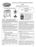
EMPIRE
Comfort Systems
INSTALLATION INSTRUCTIONS
AND
OWNER'S MANUAL
The Heritage Cast Iron Stoves
CAST IRON
UNVENTED ROOM HEATER
MODELS
VFP30CA30(B,F,M,S,W)N-1
VFP30CA30(B,F,M,S,W)P-1
GAS-FIRED
This appliance may be installed in an aftermarket,
permanently located, manufactured (mobile) home,
where not prohibited by local codes.
This appliance is only for use with the type of gas
indicated on the rating plate. This appliance is not
convertible for use with other gases.
WARNING: If the information in these instructions are not followed exactly, a fire or explosion
may result causing property damage, personal
injury or loss of life.
— Do not store or use gasoline or other flammable vapors and liquids in the vicinity of this or
any other appliance.
— WHAT TO DO IF YOU SMELL GAS
• Do not try to light any appliance.
• Do not touch any electrical switch; do not
use any phone in your building.
• Immediately call your gas supplier from a
neighbor’s phone. Follow the gas supplier’s instructions.
• If you cannot reach your gas supplier, call
the fire department.
— Installation and service must be performed by
a qualified installer, service agency or the gas
supplier.
Installer: Leave this manual with the appliance.
Consumer: Retain this manual for future
reference.
This is an unvented gas-fired heater. It uses air
(oxygen) from the room in which it is installed.
Provisions for adequate combustion and ventilation
air must be provided. Refer to page 7 .
WARNING: If not installed, operated and maintained in accordance with the manufacturer's
instructions, this product could expose you to
substances in fuel or from fuel combustion which
can cause death or serious illness.
WATER VAPOR: A BY-PRODUCT OF
UNVENTED ROOM HEATERS
Water vapor is a by-product of gas combustion. An
unvented room heater produces approximately one
(1) ounce (30 ml) of water for every 1,000 BTU's
(.3KW's) of gas input per hour. Refer to page 6.
Page 1
TABLE OF CONTENTS
SECTION
PAGE
IMPORTANT SAFETY INFORMATION .............................................................................3
SAFETY INFORMATION FOR USERS OF LP-GAS .........................................................4
INTRODUCTION ..................................................................................................................5
SPECIFICATIONS.................................................................................................................6
WATER VAPOR: A BY-PRODUCT OF UNVENTED ROOM HEATERS..........................6
PROVISIONS FOR ADEQUATE COMBUSTION & VENTILATION AIR .......................7
GAS SUPPLY.........................................................................................................................8
CLEARANCES ......................................................................................................................9
ADJUSTING AIR SHUTTER .............................................................................................10
LOG PLACEMENT .............................................................................................................11
OPERATING GUIDELINES ...............................................................................................12
LIGHTING INSTRUCTIONS .............................................................................................13
PILOT FLAME CHARACTERISTICS ...............................................................................14
MAIN BURNER FLAME CHARACTERISTICS ..............................................................15
WIRING ....................................................................................................................... 16 - 17
MAINTENANCE.................................................................................................................17
TROUBLESHOOTING ............................................................................................... 18 - 19
HOW TO ORDER REPAIR PARTS ....................................................................................19
PARTS LIST .........................................................................................................................20
PARTS VIEW .......................................................................................................................21
CASTING PARTS LIST ......................................................................................................22
CASTING PARTS VIEW ....................................................................................................23
ACCESSORY SIDE SHELVES INSTALLATION INSTRUCTIONS ...............................24
OPTIONAL STONE INLAY INSTALLATION INSTRUCTIONS ....................................24
OPTIONAL BLOWER INSTALLATION INSTRUCTIONS ..................................... 25 - 27
SERVICE NOTES .......................................................................................................... 28-30
QUICK REFERENCE .........................................................................................................31
Page 2
24214-1-0808
IMPORTANT SAFETY INFORMATION
THIS IS A HEATING APPLIANCE
DO NOT OPERATE THIS APPLIANCE WITHOUT FRONT PANEL INSTALLED.
• An unvented room heater having an input rating of more than
6,000 Btu per hour shall not be installed in a bathroom.
• An unvented room heater having an input rating of more
than 10,000 Btu per hour shall not be installed in a bedroom
or bathroom.
• Due to high temperatures, the appliance should be located
out of traffic and away from furniture and draperies.
• Children and adults should be alerted to the hazard of high
surface temperature and should stay away to avoid burns
or clothing ignition.
• Young children should be carefully supervised when they
are in the same room with the appliance.
• Do not place clothing or other flammable material on or
near the appliance.
• Keep burner and control compartment clean.
• Installation and repair should be done by a QUALIFIED
SERVICE PERSON. The appliance should be inspected
before use and at least annually by a professional service
person. More frequent cleaning may be required due to
excessive lint from carpeting, bedding materials, etc. It
is imperative that control compartments, burners and
circulating air passageways of the appliance be kept
clean.
• WARNING: ANY CHANGE TO THIS HEATER OR ITS
CONTROLS CAN BE DANGEROUS.
Any safety screen or guard removed for servicing an appliance must be replaced prior to operating the heater.
• WARNING: DO NOT operate this appliance unless
all components including logs, burners, and controls
are in good working condition. Never operate this
appliance if any log or twig is broken, or out of their
intended position. Refer to the Log set placement
instructions for correct log and twig positioning.
Replacement components are available through your local
dealer as indicated in the How to Order Repair Parts section
of the appliance manual.
• DO make a periodic visual check of pilot and burners. Clean
and replace damaged parts.
• DO NOT use this room heater if any part has been under
water. Immediately call a qualified service technician to
inspect the room heater and to replace any part of the
control system and any gas control which has been under
water.
• Due to high surface temperatures, keep children, clothing
and furniture away.
• Under no circumstances should any solid fuels (wood, coal,
paper or cardboard etc.) be used in this appliance.
• The flow of combustion and ventilation air must not be
obstructed in any way.
• WARNING: Failure to keep the primary air opening(s)
of the burner(s) clean may result in sooting and property
damage.
• Keep appliance area clear and free from combustible materials, gasoline and other flammable vapors and liquids.
• WARNING: Do not use a blower insert, heat exchanger insert
or other accessory not approved for use with heater.
WARNING
When used without adequate combustion and ventilation air,
heater may give off CARBON MONOXIDE, an odorless,
poisonous gas.
Do not install heater until all necessary provisions are
made for combustion and ventilation air. Consult the written instructions provided with the heater for information
concerning combustion and ventilation air. In the absence
of instructions, refer to the National Fuel Gas Code, ANSI
Z223.1/NFPA 54, Air for Combustion and Ventilation, or
applicable local codes.
This heater is equipped with a PILOT LIGHT SAFETY
SYSTEM designed to turn off the heater if not enough fresh
air is available.
DO NOT TAMPER WITH PILOT LIGHT SAFETY
SYSTEM!
If heater shuts off, do not relight until you provide fresh air.
If heater keeps shutting off, have it serviced. Keep burner
and control compartment clean.
24214-1-0808
CARBON MONOXIDE POISONING MAY LEAD TO
DEATH.
Early signs of carbon monoxide poisoning resemble the flu,
with headache, dizziness and/or nausea. If you have these
signs, heater may not be working properly. Get fresh air at
once! Have heater serviced.
Some people — pregnant women, persons with heart or lung
disease, anemia, those under the influence of alcohol , those
at high altitudes — are more affected by carbon monoxide
than others.
The pilot light safety system senses the depletion of oxygen
at its location. If this heater is installed in a structure having a high vertical dimension, the possibility exists that the
oxygen supply at the higher levels will be less than that at
the heater. In this type of application, a fan to circulate the
structure air will minimize this effect. The use of this fan will
also improve the comfort level in the structure. When a fan is
used to circulate air, it should be located so that the air flow
is not directed at the burner.
Page 3
SAFETY INFORMATION FOR USERS OF LP-GAS
Propane (LP-Gas) is a flammable gas which can cause fires
and explosions. In its natural state, propane is odorless and
colorless. You may not know all the following safety precautions which can protect both you and your family from an
accident. Read them carefully now, then review them point
by point with the members of your household. Someday when
there may not be a minute to lose, everyone's safety will depend
on knowing exactly what to do. If, after reading the following
information, you feel you still need more information, please
contact your gas supplier.
LP-GAS WARNING ODOR
If a gas leak happens, you should be able to smell the gas because of the odorant put in the LP-Gas.
That's your signal to go into immediate action!
• Do not operate electric switches, light matches, use your phone.
Do not do anything that could ignite the gas.
• Get everyone out of the building, vehicle, trailer, or area. Do
that IMMEDIATELY.
• Close all gas tank or cylinder supply valves.
• LP-Gas is heavier than air and may settle in low areas such as
basements. When you have reason to suspect a gas leak, keep
out of basements and other low areas. Stay out until firefighters
declare them to be safe.
• Use your neighbor's phone and call a trained LP-Gas service
person and the fire department. Even though you may not continue to smell gas, do not turn on the gas again. Do not re-enter
the building, vehicle, trailer, or area.
• Finally, let the service man and firefighters check for escaped
gas. Have them air out the area before you return. Properly
trained LP-Gas service people should repair the leak, then check
and relight the gas appliance for you.
NO ODOR DETECTED - ODOR FADE
Some people cannot smell well. Some people cannot smell the
odor of the chemical put into the gas. You must find out if you
can smell the odorant in propane. Smoking can decrease your
ability to smell. Being around an odor for a time can affect your
sensitivity or ability to detect that odor. Sometimes other odors
in the area mask the gas odor. People may not smell the gas odor
or their minds are on something else. Thinking about smelling a
gas odor can make it easier to smell.
The odorant in LP-gas is colorless, and it can fade under some
circumstances. For example, if there is an underground leak, the
movement of the gas through soil can filter the odorant. Odorants
in LP-Gas also are subject to oxidation. This fading can occur if
there is rust inside the storage tank or in iron gas pipes.
The odorant in escaped gas can adsorb or absorb onto or into walls,
masonry and other materials and fabrics in a room. That will take
some of the odorant out of the gas, reducing its odor intensity.
LP-Gas may stratify in a closed area, and the odor intensity could
vary at different levels. Since it is heavier than air, there may be
more odor at lower levels. Always be sensitive to the slightest gas
odor. If you detect any odor, treat it as a serious leak. Immediately
go into action as instructed earlier.
SOME POINTS TO REMEMBER
• Learn to recognize the odor of LP-gas. Your local LP-Gas
Dealer can give you a "Scratch and Sniff" pamphlet. Use it to
find out what the propane odor smells like. If you suspect that
your LP-Gas has a weak or abnormal odor, call your LP-Gas
Dealer.
• If you are not qualified, do not light pilot lights, perform service,
or make adjustments to appliances on the LP-Gas system. If
you are qualified, consciously think about the odor of LP-Gas
prior to and while lighting pilot lights or performing service or
making adjustments.
• Sometimes a basement or a closed-up house has a musty smell
that can cover up the LP-Gas odor. Do not try to light pilot
lights, perform service, or make adjustments in an area where
the conditions are such that you may not detect the odor if there
has been a leak of LP-Gas.
• Odor fade, due to oxidation by rust or adsorption on walls of
new cylinders and tanks, is possible. Therefore, people should
be particularly alert and careful when new tanks or cylinders
are placed in service. Odor fade can occur in new tanks, or
Page 4
reinstalled old tanks, if they are filled and allowed to set too
long before refilling. Cylinders and tanks which have been out
of service for a time may develop internal rust which will cause
odor fade. If such conditions are suspected to exist, a periodic
sniff test of the gas is advisable. If you have any question about
the gas odor, call your LP-gas dealer. A periodic sniff test of
the LP-gas is a good safety measure under any condition.
• If, at any time, you do not smell the LP-Gas odorant and you
think you should, assume you have a leak. Then take the same
immediate action recommended above for the occasion when
you do detect the odorized LP-Gas.
• If you experience a complete "gas out," (the container is under
no vapor pressure), turn the tank valve off immediately. If the
container valve is left on, the container may draw in some air
through openings such as pilot light orifices. If this occurs, some
new internal rusting could occur. If the valve is left open, then
treat the container as a new tank. Always be sure your container
is under vapor pressure by turning it off at the container before
it goes completely empty or having it refilled before it is completely empty.
24214-1-0808
INTRODUCTION
Always consult your local Building Department regarding regulations,
codes or ordinances which apply to the installation of an unvented
room heater.
This appliance may be installed in an aftermarket* permanently
located, manufactured (mobile) home, where not prohibited by state
or local codes.
*Aftermarket: Completion of sale, not for purpose of resale, from the
manufacturer.
This appliance is only for use with the type of gas indicated on the
rating plate.
Instructions to Installer
1. Installer must leave instruction manual with owner after
installation.
2. Installer must have owner fill out and mail warranty card supplied
with unvented room heater.
3. Installer should show owner how to start and operate unvented
room heater.
This product is design certified in accordance with American National
Standards Institute Z21.11.2 by Underwriters Laboratories (UL) as
an Unvented Room Heater and should be installed according to these
instructions.
Notice: Remove screw in valve cover. Screw is required to prevent
shipping damage.
Attention: During initial use of ceramic log you will detect an odor
as the ceramic log is cured.
Any alteration of the original design, installed other than as shown
in these instructions or use with a type of gas not shown on the
rating plate is the responsibility of the person and company making
the change. Do not operate this appliance unless all components
including logs, burners, and controls are in good working condition.
Never operate this appliance if any log or twig is broken, or out
of their intended position. Refer to Log Placement on page 11 for
correct log and twig positioning.
Replacement parts are available through your local dealer as
indicated in the Parts Sections on pages 19 through 23.
Warning: This appliance is equipped for (natural or propane)
gas. Field conversion is not permitted.
Warning: This unit is not for use with solid fuels.
Important
All correspondence should refer to complete Model Number, Serial
Number and type of gas.
Notice: During initial firing of this unit, its paint will bake out, and
smoke may occur. To prevent triggering of smoke alarms, ventilate
the room in which the unit is installed.
Installation in Residential Garages
Gas utilization equipment in residential garages shall be installed so
that all burners and burner ignition devices are located not less than
18" (457 mm) above the floor.
Such equipment shall be located, or protected, so it is not subject to
physical damage by a moving vehicle.
placement. Do not install unit with damaged, incomplete, or substitute
parts. Read all instructions before starting installation and follow these
instructions carefully during installation to insure maximum benefit
and safety. Failure to follow them will void your warranty and may
present a fire hazard.
The warranty will be voided by, and the warranter disclaims any
responsibility for the following actions:
•
Installation of any damaged fireplace.
•
Modification of the fireplace.
•
Installation other than as instructed by Empire Comfort Systems
Inc.
•
Improper positioning of the logs.
•
Installation and/or use of any component part not manufactured
or approved by manufacturer.
Qualified Installing Agency
Installation and replacement of gas piping, gas utilization equipment or
accessories and repair and servicing of equipment shall be performed
only by a qualified agency. The term "qualified agency" means any
individual, firm, corporation or company which either in person
or through a representative is engaged in and is responsible for (a)
the installation or replacement of gas piping or (b) the connection,
installation, repair or servicing of equipment, who is experienced in
such work, familiar with all precautions required and has complied
with all the requirements of the authority having jurisdiction.
State of Massachusetts: The installation must be made by a licensed
plumber or gas fitter in the Commonwealth of Massachusetts.
Sellers of unvented propane or natural gas-fired supplemental room
heaters shall provide to each purchaser a copy of 527 CMR 30 upon
sale of the unit. In the State of Massachusetts, unvented propane or
natural gas fired space heaters shall be prohibited in bedrooms and
bathrooms.
The installation must conform with local codes or, in the absence of local
codes, with the National Fuel Gas Code, ANSI Z223.1/NFPA 54.*
*Available from the American National Standards Institute, Inc., 11
West 42nd St., New York, N.Y. 10036.
Warning: ANY CHANGE TO THIS FIREPLACE OR ITS
CONTROLS CAN BE DANGEROUS.
Improper installation or use of the fireplace can cause serious
injury or death from fire, burns, explosions, or carbon monoxide
poisoning.
Any alteration of the original design, installed other than shown
in these instructions or use with a type of gas not shown on the
rating plate is the responsibility of the person and company making
the change.
High Altitudes
For altitudes/elevations above 2,000 feet (610 m), ratings should be
reduced at the rate of 4 percent for each 1,000 feet (305 m) above sea
level. Contact the manufacturer or your gas company before changing
spud/orifice size.
Preparation
This vent free gas fireplace and its components are tested and safe
when installed in accordance with this Installation Manual. Report
to your dealer any parts damaged in shipment, specifically check log
24214-1-0808
Page 5
SPECIFICATIONS
Model
Input BTU/HR (KW/H) Maximum
BTU/HR (KW/H) Minimum
Height
Width
Depth
Gas Inlet
VFP30CA30(B,F,M,S,W)
32,000 (9.4)
22,400 (6.6)
27 3/4" (704.9 mm)
28 1/16" (712.8 mm)
17 1/8" (435.0 mm)
3/8" (9.5 mm)
Accessories
Shelf Kit - Includes both left & right shelves
CSK-B
Porcelain Black
CSK-F
Matte Black
CSK-M
Porcelain Mahogany
CSK-S
Porcelain Sand
CSK-W
Matte Pewter
Accessories
FRBC
Battery Operated Remote Control
FRBTC
Battery Operated Remote Control w/Thermostat
FRBTP
7-Day Programmable Remote
FREC
Electric Remote Control
FWS
Wall Switch
TMV
Millivolt Wall Thermostat - Reed Switch
TRW
Remote Wall Thermostat
CIB
Automatic Blower
Stone Inlay Replaces Standard Grill Top
CSI-8V
Stone Inlay
Venetian Gold
CSI-9A
Stone Inlay
Adobe Frost
CSI-10M
Stone Inlay
Patina Mocha
Stone Inlay
Temple Gray
CSI-11G
CSI-12A
Stone Inlay
American Beauty
WATER VAPOR: A BY-PRODUCT OF UNVENTED ROOM HEATERS
Water vapor is a by-product of gas combustion. An unvented room
heater produces approximately one (1) ounce (30 ml) of water for
every 1,000 BTU's (.3KW's) of gas input per hour.
Unvented room heaters must be used as supplemental heat
(a room) rather than a primary heat source (an entire house). In most
supplemental heat applications, the water vapor does not create a
problem. In most applications, the water vapor enhances the low
humidity atmosphere experienced during cold weather.
Page 6
The following Steps will help insure that water vapor does not
become a problem.
1. Be sure the heater is sized properly for the application, including
ample combustion air and circulation air.
2. If high humidity is experienced, a dehumidifier may be used to
help lower the water vapor content of the air.
3. Do not use an unvented room heater as the primary heat source
(an entire house).
24214-1-0808
PROVISIONS FOR ADEQUATE COMBUSTION & VENTILATION AIR
This heater shall not be installed in a confined space or unusually
tight construction unless provisions are provided for adequate
combustion and ventilation air.
The National Fuel Gas Code, ANSI Z223.1 defines a confined space
as a space whose volume is less than 50 cubic feet per 1,000 Btu per
hour (4.8 m3 per kw) of the aggregate input rating of all appliances
installed in that space and an unconfined space as a space whose
volume is not less than 50 cubic feet per 1,000 Btu per hour (4.8 m3
per kw) of the aggregate input rating of all appliances installed in
that space. Rooms communicating directly with the space in which
the appliances are installed, through openings not furnished with
doors, are considered a part of the unconfined space.
The following example is for determining the volume of a typical
area in which the VFP30 may be located and for determining if
this area fits the definition of an unconfined space.
The maximum input of the VFP30 is 32,000 Btu per hour. Based
on the 50 cubic feet per 1,000 Btu per hour formula, the minimum
area that is an unconfined space for installation of the VFP30 is
1,600 cubic feet, 50 cubic feet x 32 = 1,600 cubic feet. To determine
the cubic feet of the area in which the VFP30 is to be installed,
measure the length, width and height of the area. Example: The
area measures 17 feet in length, 12 feet in width and 8 feet in
height, the area is 1,632 cubic feet. The VFP30 can be installed
in this unconfined space with no requirement to provide additional
combustion and ventilation air.
24214-1-0808
Warning: If the area in which the heater may be operated is smaller
than that defined as an unconfined space or if the building is of
unusually tight construction, provide adequate combustion and
ventilation air by one of the methods described in the National
Fuel Gas Code, ANSI Z223.1/NFPA 54, Air for Combustion and
Ventilation, or applicable local codes.
Unusually Tight Construction
The air that leaks around doors and windows may provide enough
fresh air for combustion and ventilation. However, in buildings of
unusually tight construction, you must provide additional fresh
air.
Unusually tight construction is defined as construction
where:
a. Walls and ceilings exposed to the outside atmosphere have
a continuous water vapor retarder with a rating of one perm
or less with openings gasketed or sealed, and
b. Weather-stripping has been added on openable windows and
doors, and
c. Caulking or sealants are applied to areas such as joints
around window and door frames, between sole plates and
floors, between wall-ceiling joints, between wall panels, at
penetrations for plumbing, electrical, and gas lines, and at
other openings.
If the VFP30 heater is installed in a building of unusually tight
construction, adequate air for combustion, ventilation and dilution of flue gases shall be provided in accordance with ANSI
Z223.1/NFPA54.
Page 7
GAS SUPPLY
Check all local codes for requirements, especially for the size and
type of gas supply line required.
Recommended Gas Pipe Diameter
Pipe Length
Schedule 40 Pipe
Tubing, Type L
Inside Diameter
Outside Diameter
Nat.
L.P.
Nat.
L.P.
0-10 feet
1/2”
3/8”
1/2”
3/8”
0-3 meters 12.7 mm 9.5 mm 12.7 mm
9.5 mm
10-40 feet
1/2”
1/2”
5/8”
1/2”
4-12 meters 12.7 mm 12.7 mm 15.9 mm 12.7 mm
40-100 feet
1/2”
1/2”
3/4”
1/2”
13-30 meters 12.7 mm 12.7 mm 19 mm
12.7 mm
100-150 feet
3/4”
1/2”
7/8”
3/4”
31-46 meters 19 mm 12.7 mm 22.2 mm
19 mm
Note: Never use plastic pipe. Check to confirm whether your local
codes allow copper tubing or galvanized.
Note: Since some municipalities have additional local codes, it is
always best to consult your local authority and installation code.
Installing a New Main Gas Cock
Each appliance should have its own manual gas cock.
A manual main gas cock should be located in the vicinity of
the unit. Where none exists, or where its size or location is not
adequate, contact your local authorized installer for installation
or relocation.
Compounds used on threaded joints of gas piping shall be resistant
to the action of liquefied petroleum gases. The gas lines must be
checked for leaks by the installer. This should be done with a soap
solution watching for bubbles on all exposed connections, and if
unexposed, a pressure test should be made.
Never use an exposed flame to check for leaks. Appliance must
be disconnected from piping at inlet of control valve and pipe
capped or plugged for pressure test. Never pressure test with
appliance connected; control valve will sustain damage!
A gas valve and ground joint union should be installed in the gas
line upstream of the gas control to aid in servicing. It is required
by the National Fuel Gas Code that a drip line be installed near
the gas inlet. This should consist of a vertical length of pipe tee
connected into the gas line that is capped on the bottom in which
condensation and foreign particles may collect.
The use of the following gas connectors is recommended:
— ANS Z21.24 Appliance Connectors of Corrugated Metal Tubing
and Fittings
— ANS Z21.45 Assembled Flexible Appliance Connectors of
Other Than All-Metal Construction
The above connectors may be used if acceptable by the authority
having jurisdiction The state of Massachusetts requires that a flexible
appliance connector cannot exceed three feet in length.
Page 8
Figure 1
Pressure Testing of the Gas Supply System
1. To check the inlet pressure to the gas valve, a 1/8" (3 mm) N.P.T.
plugged tapping, accessible for test gauge connection, must be
placed immediately upstream of the gas supply connection to
the appliance.
2. The appliance and its individual shutoff valve must be
disconnected from the gas supply piping system during any
pressure testing of that system at test pressures in excess of
1/2 psig (3.5 kPa).
3. The appliance must be isolated from the gas supply piping
system by closing its individual manual shutoff valve during
any pressure testing of the gas supply piping system at test
pressures equal to or less than 1/2 psig (3.5 kPa).
Attention! If one of the above procedures results in pressures in
excess of 1/2 psig (14" w.c.) (3.5 kPa) on the appliance gas valve,
it will result in a hazardous condition.
Checking Manifold Pressure
Natural gas will have a manifold pressure of approximately
3.5" w.c. (.871 kPa) for maximum input or 1.7" w.c. (.423 kPa) for
minimum input at the pressure regulator outlet with the inlet pressure
to the pressure regulator from a minimum of 4.5" w.c. (1.245 kPa)
for the purpose of input adjustment to a maximum of 10.5" w.c.
(2.614 kPa). Propane gas will have a manifold pressure approximately
10.0" w.c. (2.49 kPa) for maximum input or 6.3" w.c. (1.568 kPa)
for minimum input at the pressure regulator outlet with the inlet
pressure to the pressure regulator from a minimum of 11.0" w.c.
(2.739 kPa) for the purpose of input adjustment to a maximum of
13.0" w.c. (3.237 kPa).
NOTE: The gas control is equipped with a captured screw type
pressure test point, therefore it is not necessary to provide a 1/8"
test point up stream of the control.
A test gauge connection is located downstream of the gas appliance
pressure regulator for measuring gas pressure. The connection is a
1/8 inch (3 mm) N.P.T. plugged tapping.
24214-1-0808
CLEARANCES
Clearances (Figures 2, 3, and 4)
When facing the front of the appliance the following minimum
clearances to combustible construction must be maintained.
Top of appliance (ceiling)
36 inches
Rear Wall
2 inches
Side Wall
6 inches
Heater Corners (45° angle) to Wall
4 inches
Floor
0 inches
4” (102mm) HEATER CORNERS
TO SIDE WALL
Provide adequate clearances around air openings.
Adequate accessibility clearances for purposes of servicing and
proper operation must be provided.
Installation on Rugs and Tile
This appliance must be installed on a flat, solid, continuous surface
(e.g. wood, metal, concrete). This may be the floor, or it may be
raised up on a platform to enhance its visual impact. The appliance may be installed on carpeting, vinyl, wood flooring or other
combustible material.
NOTE: HEATER INSTALLED AT
45° ANGLE IN CORNER
4”
(102mm)
Figure 3
36” (91cm) TO CEILING OR
HORIZONTAL PROJECTION
ABOVE APPLIANCE
6” (153mm) TO SIDE WALL
OR COMBUSTIBLE
MATERIAL
Figure 2
2” (51mm) TO COMBUSTIBLE MATERIAL
Figure 4
24214-1-0808
Page 9
ADJUSTING AIR SHUTTER
The air shutter has been factory set to the optimum performance
level for this appliance. LP air shutter is not adjustable.
1.
2.
3.
4.
5.
6.
7.
8.
9.
10.
11.
12.
13.
14.
15.
16.
Remove cast iron top and carefully set aside.
Remove cast iron front and carefully set aside.
Remove screen door by removing two (2) screws. See Figure
5.
Carefully remove logs and set aside.
Remove the log shelf by removing the two (2) screws securing
the log shelf to the rear wall. See Figure 6.
Remove the burner by removing the two (2) screws at the front
of the burner as shown in Figure 7.
Carefully remove the burner by lifting straight up.
Loosen the two (2) nuts on the air shutter shown in Figure 8 to
adjust the air shutter. Figure 8 call-out demonstrates the proper
locations for Natural Gas. LP utilizes a fixed air shutter.
Tighten the two (2) nuts back down locking the air shutter in
place. Be sure that the air shutter is the same distance from
the burner orifice on both sides of the air shutter for proper
burner fit up.
Carefully replace the burner by dropping it down over the
orifice holder and air shutter lining up the front mounting holes
with the holes on the firebox.
Replace the two (2) screws at the front of the burner shown in
Figure 7.
Replace the log shelf by replacing the two (2) screws removed
in Step 4 securing the log shelf to the rear wall.
Replace Logs. See Page 11.
Replace the screen door by replacing the two (2) screws removed in Step 3.
Replace cast iron front.
Replace cast iron top.
Figure 6
Figure 7
Note: Be sure air shutter is adjusted and tightened evenly to
ensure proper fit, failure to evenly adjust air shutter can cause
improper combustion. Only a certified technician should adjust
the air shutter.
DIM. “A”
NAT
9/16”
LPG
1”
LOOSEN (2) NUTS
DIM. “A”
Figure 5
Page 10
Figure 8
24214-1-0808
LOG PLACEMENT
1.
2.
3.
4.
5.
6.
7.
8.
9.
10.
11.
12.
13.
14.
15.
Remove cast iron top and carefully set aside.
Remove cast iron front and carefully set aside.
Lower valve cover on firebox.
Release two door latches at bottom of firebox.
Grasp bottom of glass frame, lift glass frame upward in order
to release glass frame from lip on top of firebox.
Remove logs from shipping crate. Remove all protective
packaging from logs and interior of firebox.
Place rear log onto two (2) pins on rear log support.
Place center left front log onto flat portion of left side of
burner.
Place right front log onto flat portion on right side of burner. Toe
of right front log should rest in groove on ember bed twig.
Place front left log chunk onto flat portion of burner on left
front side.
Place left twig onto left side pin on rear log with toe resting
on the groove in the left front log.
Place right twig onto right side pin on rear log with toe resting
all the way to the right on the right front log.
Align and place top of glass frame over lip on top of firebox.
Grasp bottom of glass frame, push inward and place glass
frame onto firebox.
Attach two door latches to bottom of firebox.
Log placement is completed.
LEFT TWIG
RIGHT TWIG
REAR LOG
FRONT
RIGHT LOG
CENTER
LEFT LOG
FRONT LEFT
LOG CHUNK
BURNER TOP
Figure 9
16. Install cast iron front.
17. Install cast iron top.
Refer to Figure 9 for the following warning.
Warning: Failure to position the parts in accordance with
this diagram or failure to use only parts specifically approved
with this appliance may result in property damage or personal
injury.
LEFT TWIG
REAR LOG
RIGHT TWIG
FRONT LEFT
LOG CHUNK CENTER
LEFT LOG
Log Placement - Top View
24214-1-0808
FRONT
RIGHT LOG
LEFT TWIG
FRONT LEFT
LOG CHUNK
REAR LOG
RIGHT TWIG
CENTER
LEFT LOG
FRONT
RIGHT LOG
Log Placement - Front View
Page 11
OPERATING GUIDELINES
Before operating this heater, please review the safety warnings
pages at the beginning of this manual and those precautions and
warnings listed below.
1. Know what type of ignition system this model has (standing
pilot) and follow the applicable SAFETY and LIGHTING
instructions.
2. Check to ensure there are no gas leaks. If you are unsure, turn gas
off to the heater and call a service person or your gas utility.
CAUTION: Clothing or other flammable material should not
be placed on or near the appliance.
WARNING: Children and adults should be alerted to the
hazard of high surface temperature and should stay away
to avoid burns or clothing ignition. Young children should
be carefully supervised when they are in the same room as
the appliance.
3. Tampering is DANGEROUS and voids all warranties. Any
component that is found to be faulty, must be replaced with an
approved component.
Initial Lighting (Figure 10)
Upon completing the gas line or turning the gas valve "ON" after it
has been in the "OFF" position, a small amount of air will be in the
lines. When first lighting the appliance, it will take a few minutes
for the lines to purge themselves of this air. Once the purging is
complete, the appliance will light and operate satisfactorily.
Subsequent lightings of the appliance will not require such purging
if the gas valve is not turned to "OFF."
Standing Pilot Operation
1. Follow the SAFETY and LIGHTING INSTRUCTIONS for
standing pilot controls found in this manual and on labels found
attached to the appliance.
Page 12
CAUTION: During the initial purging and subsequent lightings,
never allow the gas valve control knob to remain depressed in
the "pilot" position without pushing the piezo ignitor button
at least once every second.
2. D u r i n g t h e
heating season,
leave
the
control valve
knob in the
"ON" position.
This will allow
the pilot flame
to remain lit.
Turn the burner
Figure 10
flame on or off
with the appliance REMOTE/OFF/ON rocker switch, wall
switch, remote control kits or 750 millivolt wall thermostat.
NOTE: The gas control valve allows you to increase or decrease the
height of the main burner flame. The control valve has a pressure
regulator with a knob as shown in Figure 10 . Rotate the knob
clockwise to "HI" to increase the flame height and counterclockwise
to "LO" to decrease the flame height.
3. When the heating season is over, turn the REMOTE/OFF/ON
switch to "OFF" and the control valve to "OFF". The system,
including the pilot light, will be shut down.
Maximum and Minimum Input
The gas valve on the appliance allows the input to adjust between
a maximum input of 32,000 Btuh to a minimum input of 22,400
Btuh. Please be advised, the maximum input provides the greatest
amount of yellow flame and ember glow on the log set. The minimum
input substantially decreases the yellow flame and ember glow on
the log set.
24214-1-0808
LIGHTING INSTRUCTIONS
FOR YOUR SAFETY READ BEFORE LIGHTING
WARNING: IF YOU DO NOT FOLLOW THESE INSTRUCTIONS EXACTLY, A FIRE OR EXPLOSION MAY RESULT CAUSING PROPERTY DAMAGE, PERSONAL INJURY OR LOSS OF LIFE.
A. This appliance has a pilot which must be lighted by hand.
When lighting the pilot, follow these instructions exactly.
B. BEFORE LIGHTING smell all around the appliance area for
gas. Be sure to smell next to the floor because some gas is
heavier than air and will settle on the floor.
WHAT TO DO IF YOU SMELL GAS
• Do not try to light any appliance
• Do not touch any electrical switch; do not use any phone
in your building
• Immediately call your gas supplier from a neighbor's
phone. Follow the gas supplier's instructions.
•
If you can not reach your gas supplier, call the fire department.
C. Use only your hand to push in or turn the gas control knob.
Never use tools. If the knob will not push in or turn by hand,
don't try to repair it, call a qualified service technician. Force
or attempted repair may result in a fire or explosion.
D. Do not use this appliance if any part has been under water.
Immediately call a qualified service technician to inspect the
appliance and to replace any part of the control system and
any gas control which has been under water.
LIGHTING INSTRUCTIONS
1.
STOP! Read the safety information above.
2.
Set the thermostat to lowest setting.
3.
Turn off all electric power to the appliance (if applicable).
4.
Lower valve cover.
5.
Push in gas control knob slightly
and turn clockwise
to "OFF."
NOTE: Knob cannot be turn from
"PILOT" to "OFF" unless knob is pushed in slightly. Do not
force.
6.
9.
Wait ten (10) minutes to clear out any gas. Then smell for
gas, including near the floor. If you smell gas, STOP! Follow "B" in the safety
information above on
this plate. If you do not
smell gas, go to the next
Step.
•
•
Push in control knob all the way and hold in. Repeatedly
push the Piezo Ignitor Button until the pilot is lit. Continue
to hold the control knob in for about one (1) minute after the
pilot is lit. Release knob and it will pop back up. Pilot should
remain lit. If it goes out, repeat Steps 5 through 9.
If knob does not pop up when released, stop and immediately call a qualified service technician or gas supplier.
If the pilot will not stay lit after several tries, turn the gas
control knob to "OFF" and call your service technician or
gas supplier.
10. Attention! Gas control has an INTERLOCK latching device. When the pilot is initially lit and the safety magnet is
energized (pilot stays "on"), the INTERLOCK latching device becomes operative. If the gas control is turned to "OFF"
position or gas flow to the appliance shut off, the pilot cannot be relighted until the safety magnet is de-energized (approximately 60 seconds). There will be an audible "click"
when the safety magnet in the gas control is de-energized.
Pilot can now be relighted. Repeat Steps 5 thru 9.
11. Turn gas control knob counterclockwise
7.
Find pilot - The pilot is attached to the main burner behind
the front log.
12. Raise valve cover.
8.
Turn gas control knob counterclockwise
"PILOT."
14. Set thermostat to desired setting.
to
to "ON."
13. Turn on all electric power to the appliance (if applicable).
TO TURN OFF GAS APPLIANCE
1.
Set the thermostat to lowest setting.
4.
2.
Turn off all electric power to the appliance if service is to be
performed (if applicable).
Push in gas control knob slightly and turn clockwise
to "OFF."
5.
Raise valve cover.
3.
Lower valve cover.
24214-1-0808
Page 13
PILOT FLAME CHARACTERISTICS
Figure 11 shows a correct pilot flame pattern. The correct flame
will be blue and will extend beyond the thermocouple and thermopile. The flame will surround the thermocouple and thermopile
just below the tip. A slight yellow flame may occur where the pilot
flame and main burner flame meet. Figure 12 shows an incorrect
pilot flame pattern. The incorrect pilot flame is not touching the
thermocouple or thermopile. This will cause the thermocouple or
thermopile to cool. When the thermocouple cools, the heater will
shut down.
Cleaning and Maintenance/Pilot
Oxygen Depletion Sensor Pilot (Figure 13)
When the pilot has a large yellow tip flame, clean the Oxygen
Depletion Sensor as follows:
1. Clean the ODS pilot by loosening nut B from the pilot tubing.
When this procedure is required, grasp nut A with an open
wrench.
2. Blow air pressure through the holes indicated by the arrows.
This will blow out foreign materials such as dust, lint and spider
webs. Tighten nut B also by grasping nut A.
Figure 13
Correct Pilot Flame Pattern
Figure 11
Incorrect Pilot Flame Pattern
Figure 12
If pilot flame pattern is incorrect, as shown in Figure 12
• See Troubleshooting, pages 18 and 19.
Page 14
24214-1-0808
MAIN BURNER FLAME CHARACTERISTICS
Figure 14 shows a correct main burner flame pattern. Figure 15
shows an incorrect main burner flame pattern.
Cleaning and Maintenance / Main Burner
Warning: Turn off heater and let cool before cleaning.
If main burner flame pattern is incorrect, as shown in Figure 15:
• See Troubleshooting, pages 18 and 19.
After use, cleaning of the main burner may be required for the
proper flame. The main burner may be cleaned by applying air
pressure to the ports on the main burner.
Cleaning the Log Set and Firebox
CAUTION: Do not handle these logs with your bare hands.
Always wear gloves to prevent skin irritation.
YELLOW FLAMES
During the annual inspection and maintenance appointment, the
service person should clean dust, lint, and any light accumulation
from the logs and the firebox area. An extra-soft brush should be
used on the logs and burner as they are extremely fragile; a vacuum
cleaner may be used on the firebox. If at any time the logs cannot
be removed or installed without forcing, the cause must be found.
The logs must never be forced.
CAUTION: The ceramic logs are durable when handled and
installed properly. However, they are delicate and may be damaged
easily if not handled with care. Handling damage to the ceramic
logs is not covered by warranty.
DO NOT HANDLE LOGS WHILE THEY ARE HOT. ALLOW
PLENTY OF TIME FOR THE APPLIANCE TO COOL COMPLETELY BEFORE HANDLING.
PLEASE NOTE
It is normal for appliances fabricated of steel to give off
some expansion and/or contraction noises during the start
up or cool down cycle. Similar noises are found with your
furnace heat exchanger or car engine.
Correct Main Burner Flame
Figure 14
BLUE FLAMES
Incorrect Main Burner Flame
Figure 15
24214-1-0808
Page 15
WIRING
ON/OFF/REMOTE Switch
This product is equipped with an ON/OFF/REMOTE switch which
is located on the wire channel. A wire harness is attached to the
ON/OFF/REMOTE switch. The red, black and green (wires) female
push-ons attach to the ON/OFF/REMOTE switch. At the opposite
end of the wire harness, the black and green (wires) female pushons attach to the gas valve. An additional green wire and the red
wire, which are stripped and bare, will attach to the 750 millivolt
wall thermostat accessory, or, to one of the other accessories that
can be purchased for use with your log set.
Operation of ON/OFF/REMOTE Switch with no Accessories
To ignite main burner, turn the control knob on the gas valve from
the PILOT position to the ON position. Turn the ON/OFF/REMOTE
switch from the OFF position to the ON position. The additional green
wire and red wire, which are stripped and bare are not used.
Operation of ON/OFF/REMOTE Switch with Accessories
750 Millivolt Wall Thermostat
Connect the green and red, stripped and bare, wires on the ON/
OFF/REMOTE switch wire harness to the wall thermostat. Turn the
ON/OFF/REMOTE switch on the wire channel to the REMOTE
position. Set the wall thermostat to the desired temperature.
It is important to use wire of a gauge proper for the length of the
wire:
RECOMMENDED WIRE GAUGES
Maximum
Length
1' to 10'
10' to 25'
25' to 35'
Wire
Gauge
18
16
14
Wall Switch, FWS-1
Connect the green and red, stripped and bare, wires on the ON/OFF/
REMOTE switch wire harness to the wall switch. Turn the ON/OFF/
REMOTE switch on the wire channel to the REMOTE position.
Pivot the rocker switch on the FWS-1 to the ON position.
Battery Operated Remote Control, FRBC, FRBTP,
TRW, and FRBTC
Connect the green and red, stripped and bare, wires on the ON/
OFF/REMOTE switch wire harness to the remote receiver that is a
component in the FRBC and FRBTC. Turn the ON/OFF/REMOTE
switch on the wire channel to the REMOTE position. Follow instructions in the FRBC and FRBTC to complete installation.
Note: If batteries fail in FRBC or FRBTC, and immediate heat is
desired, turn the ON/OFF/REMOTE switch on wire channel from
the REMOTE position to the ON position.
Wiring of ON/OFF/REMOTE Switch with 750 Millivolt Wall
Thermostat Accessory and Another Accessory
Connect the green and red, stripped and bare, wires on the ON/OFF/
REMOTE switch wire harness to the 750 millivolt wall thermostat
AND to the remote receiver that is a component in the FRBC, FREC
OR to the FWS, wall switch.
1. Connect (1) wire from the 750 millivolt wall thermostat and (1)
wire from appropriate accessory to the GREEN, stripped and
bare wire from the ON/OFF/REMOTE wire harness.
2. Connect (1) wire from the 750 millivolt wall thermostat and (1)
wire from appropriate accessory to the RED, stripped and bare
wire from the ON/OFF/REMOTE wire harness.
Note: When the appliance is in the MANUAL mode and the
batteries fail in the FRBC or if the electric (120 volt) fails in the
FREC, and immediate heat is desired, turn the ON/OFF/REMOTE
switch on wire channel from the REMOTE position to the ON
position.
Manual Operation
1. Turn ON/OFF/REMOTE switch on wire channel to REMOTE
position.
2. Turn wall thermostat OFF.
3. Turn accessory, FRBC, FREC, FRBTP, TRW or FWS, ON.
Appliance is now in the manual mode. You must turn the appliance
ON or OFF with appropriate accessory.
Wall Thermostat Operation
1. Turn the ON/OFF/REMOTE switch on wire channel to REMOTE
position.
2. Turn accessory, FRBC, FREC or FWS, OFF.
3. Turn wall thermostat ON and set appropriate temperature. Wall
thermostat will cycle the appliance ON and OFF.
Installation of Remote Receiver
(Figure 16)
1. Attach, from left to right, the slide-on cover plate onto the remote
receiver. ON will be to the top and OFF will be to the bottom
on the slide-on cover plate.
2. Push the receiver slide button onto the receiver slide switch.
Reverse installation of the slide button if it is off center.
3. Attach Velcro loop on the left side of the valve cover support.
4. Attach Velcro hook onto remote receiver. The word TOP on the
remote receiver should be to the top when installed onto valve
cover support.
5. Attach Velcro hook on remote receiver onto Velcro loop on
valve cover support.
Refer to remote control installation and operating instructions
for more details on remote control.
Electric (120 volt) Operated Remote Control, FREC
Connect the green and red, stripped and bare, wires on the ON/OFF/
REMOTE switch wire harness to the wires on remote receiver that
is a component in the FREC. Turn the ON/OFF/REMOTE switch
on the wire channel to the REMOTE position. Follow instructions
in the FREC to complete installation.
Note: If electric (120 volt) fails in FREC, and immediate heat is
desired, turn the ON/OFF/REMOTE switch on wire channel from
the REMOTE position to the ON position.
REMOTE
RECEIVER
ATTACH VELCRO TO
VALVE COVER BRACKET
Figure 16
Page 16
24214-1-0808
WIRING (continued)
Wiring Diagram
WIRING DIAGRAM
H
REMOTE CONTROL RECEIVER/
THERMOSTAT/ CONTROLE E
DISTANCE DU RECEPTEUR
N
(OPTIONAL) THERMOSTAT
(FACULATIVE) THERMOSTAT
(OPTIONAL) WALL SWITCH
INTERRUPTEUR MURAL
(FACULTATIVE)
REMOTE/OFF/ON SWITCH
A DISTANCE/OUVERT/
FERME INTERRUPTEUR
GAS VALVE
VALVE DE GAZ
(OPTIONAL) REMOTE CONTROL RECEIVER
(FACULTATIVE) CONTROLE E DISTANCE
DU RECEPTEUR
REMOTE/OFF/ON SWITCH
A DISTANCE/FERME/OUVERT
INTERRUPTEUR
REMOTE
OFF
ON
THERMOPILE
PILOT
VEILLEUSE
THERMOCOUPLE
(LPG)
GAS VALVE
THERMOCOUPLE
(NATURAL)
IF ANY OF THE ORIGINAL WIRE
AS SUPPLIED WITH THIS UNIT
MUST BE REPLACED, IT MUST BE
REPLACED WITH NUMBER 18, 150°C
WIRE OR ITS EQUIVALENT.
SI UN DES FILS ELECTRIQUES
ORIGINAUX, VENANT DU FABRICANT
AVEC CETTE UNITE, DOIT ETRE
REMPLACE, VOUS DEVEZ LE
REMPLACER AVEC UN FIL
ELECTRIQUE DE NUMERO 18,
150 ° C DU L'EQUIVALENT.
Figure 17
MAINTENANCE
IMPORTANT: Turn off gas before servicing appliance. It is
recommended that a qualified service technician perform these
check-ups at the beginning of each heating season.
• Clean Burner and Control Compartment
Keep the control compartment, logs and burner area surrounding
the logs clean by vacuuming or brushing at least twice a year.
Cleaning Procedure (Figure 18)
1. Turn off pilot light at gas valve.
2. Remove screen front. [(2) 10 x 1/2" screws]
3. Vacuum burner compartment especially around orifice/primary
air openings. See Page 10, Adjusting Air Shutter.
4. Replace screen front. [(2) 10 x 1/2" screws]
5. Ignite pilot. (See Lighting Instructions, page 13)
6. Operate the main burner and visually check to make sure
the flame pattern appears similar to the pictorial illustration
shown for proper main burner flame pattern, Figure 14. If it
appears abnormal call a service person.
Verify proper operation after servicing.
24214-1-0808
Figure 18
Page 17
TROUBLESHOOTING
SYMPTOMS - POSSIBLE CAUSES AND CORRECTIONS
IMPORTANT: Operating heater where impurities in air exist may create odors. Cleaning supplies, paint, paint remover, cigarette smoke,
cements and glues, new carpet or textiles, etc., create fumes. These fumes may mix with combustion air and create odors.
1. When ignitor button is pressed, there is no spark at ODS/
pilot.
a. Ignitor electrode positioned wrong - Replace ignitor.
b. Ignitor electrode broken - Replace ignitor.
c. Ignitor electrode not connected to ignitor cable - Reconnect
ignitor cable.
d. Ignitor cable pinched or wet - Free ignitor cable if pinched
by any metal or tubing. Keep ignitor cable dry.
e. Broken ignitor cable - Replace ignitor cable.
f. Bad piezo ignitor - Replace piezo ignitor.
2. When ignitor button is pressed, there is spark at ODS/pilot,
but no ignition.
a. Gas supply turned off or manual shutoff valve closed - Turn
on gas supply or open manual shutoff valve.
b. Control knob not in PILOT position - Turn gas control knob
to PILOT position.
c. Control knob not pressed in while in PILOT position - Press
in control knob while in PILOT position.
d. Air in gas lines when installed - Continue holding down
control knob. Repeat igniting operation until air is
removed.
e. Depleted gas supply - Contact local gas company.
f. ODS/pilot is clogged - Clean ODS/pilot or replace ODS/pilot
assembly.
g. Gas regulator setting is not correct - Replace gas
regulator.
3. ODS/pilot lights but flame goes out when control knob is
released.
a. Control knob not fully pressed in - Press in control knob
fully.
b. Control knob not pressed in long enough - After ODS/pilot
lights, keep control knob pressed in 30 seconds.
c. Safety interlock system has been triggered (thermostat
models only) - Wait one minute for safety interlock system
to reset. Repeat ignition operation.
d. Manual Shutoff valve not fully open - Fully open manual
shutoff valve.
e. Thermocouple connection loose at control valve - Hand
tighten until snug, then tighten 1/4 turn more.
f. Pilot flame not touching thermocouple, which allows
thermocouple to cool, causing pilot flame to go out. This
problem could be caused by either 1) low gas pressure
- Contact local gas company or 2) dirty or partially
clogged ODS/pilot - Clean ODS/pilot or replace ODS/pilot
assembly.
g. Thermocouple damaged - Replace thermocouple.
h. Control valve damaged - Replace control valve.
4. Main burner does not light after ODS/pilot is lit.
a. Main burner orifice clogged - Clean main burner or replace
main burner orifice.
b. Main burner orifice diameter is too small - Replace main
burner orifice.
c. Inlet gas pressure is too low - Contact local gas
company.
Page 18
5. Pilot burning, no gas to burner, valve knob "ON", on/off
switch "ON."
a. "On/Off" switch, wall switch, remote control or wires
defective - Check "on/off" switch and wires for proper
connections. Place jumper wires across terminal at switch
- if burner comes on, replace defective switch. If OK, place
jumper wires across switch wires at gas valve-if burner
comes on, wires are faulty or connections are bad.
b. Thermopile may not be generating sufficient millivolts
- If the pilot flame is not close enough physically to the
thermopile, clean the ODS/pilot.
- Be sure the wire connections from the thermopile at the
gas valve terminals are tight and the thermopile is fully
inserted into the pilot bracket.
- Check the thermopile with a millivolt meter. Take the
reading at TH-TP & TP terminals of the gas valve. The
meter should read 350 millivolts minimum, while holding
the valve knob depressed in the PILOT position, with
the pilot lit, and the ON/OFF switch in the OFF position.
Replace the faulty thermopile if the reading is below the
specified minimum.
- With the pilot in the ON position, disconnect the thermopile
leads from the valve. Take a reading at the thermopile leads.
The reading should be 350 millivolts minimum. Replace
the thermopile if the reading is below the minimum.
c. Defective valve - Turn valve knob to "ON." Place ON/OFF
switch to "ON." Check with millivolt meter at thermopile
terminals. Millivolt meter should read greater than 200
millivolts. If the reading is okay and the main burner does
not ignite, replace the gas valve
d. Plugged main burner orifice - Check main burner orifice
for blockage and remove.
6. Delayed ignition of main burner.
a. Manifold pressure is too low - Contact local gas
company.
b. Main burner orifice clogged - Clean main burner and main
burner orifice.
7. If burning at main burner orifice occurs (a loud, roaring
blow torch noise).
a. You must turn off burner assembly and contact a qualified
service person.
b. Main burner orifice is clogged or damaged – Clean main
burner and main burner orifice or replace main burner
orifice.
c. Damaged main burner – Replace damaged main burner.
d. Gas regulator defective – Replace gas regulator.
8. Yellow flame in front section of main burner during main
burner combustion.
a. Not enough air - Check main burner for dirt and debris. If
found, clean main burner.
b. Gas regulator defective - replace gas regulator.
24214-1-0808
TROUBLESHOOTING (continued)
9. Slight smoke or odor during initial operation.
a. Residues from manufacturing processes and logs curing
- Problem will stop after a few hours of operation.
10. Heater produces a whistling noise when main burner is
lit.
a. Turning control knob to HI position when main burner is
cold - Turn control knob to LO position and let warm up
for a minute.
b. Air in gas line - Operate main burner until air is removed
from line. Have gas line checked by local gas company.
c. Air passageways on heater blocked - Observe minimum
installation clearances (see page 9).
d. Dirty or partially clogged main burner orifice - Clean main
burner and main burner orifice or replace main burner
orifice.
11. Heater produces a clicking/ticking noise just after main
burner is lit or shut off.
a. Metal expanding while heating or contracting while cooling
- This is common with most heaters. If noise is excessive,
contact service person.
12. Heater produces unwanted odor.
a. Heater burning vapors from paint, hair spray, glues, cleaners,
chemicals, new carpet, etc. - Open window to ventilate
room. Stop using odor causing products while heater is
operating.
b. Low fuel supply - Refill supply tank.
c. Gas leak - Locate and correct all leaks.
13. Heater shuts off in use (ODS operates).
a. Not enough fresh air is available - Open window and/or
door for ventilation.
b. Low line pressure - Contact local gas company.
c. ODS/pilot is partially clogged - Clean ODS/pilot.
14. Gas odor even when control knob is in OFF position.
a. Gas leak - Locate and correct all leaks.
b. Control valve defective - Replace control valve.
15. Gas odor during combustion.
a. Foreign matter between logs and main burner - remove
foreign matter.
b. Gas leak - Locate and correct all leaks.
HOW TO ORDER REPAIR PARTS
Parts can be ordered only through your service person or dealer. For best results, the service person or dealer should order parts through
the distributor. Parts can be shipped directly to the service person/dealer.
All parts listed in the Parts List have a Part Number. When ordering parts, first obtain the Model Number from the name plate on your
equipment. Then determine the Part Number (not the Index Number) and the Description of each part from the following appropriate
illustration and list. Be sure to give all this information.
Heater Model Number
Heater Serial Number
Part Number
Part Description
Type of Gas (Propane or Natural)
Do not order bolts, screws, washers or nuts. They are standard hardware items and can be purchased at any local hardware store.
Shipments contingent upon strikes, fires and all causes beyond our control.
Empire Comfort Systems, Inc. Nine Eighteen Freeburg Ave. Belleville, Illinois 62222-0529
24214-1-0808
Page 19
PARTS LIST
PLEASE NOTE: When ordering parts, it is very important that part number and description of part coincide.
INDEX NO.
1
2
3
4
5
6
7
7
8
9
10
11
12
13
13
14
14
15
16
17
18
19
20
21
22
23
23
24
25
26
27
28
29
30
31
32
33
34
35
NOT SHOWN
PART NO.
15484
24043
23938
24034
24017
15567
R-3624
R-3623
24560
24563
P-253
24429
R-7572
P-184
P-250
24215
24430
24041
15977
24024
24246
24562
R-7063
24561
R-2423
R-9368
R-3625
R-9760
15516
R-9616
R-9615
R-9613
R-9618
R-9617
R-9614
24035
24211
R-3436
24555
R-9698
DESCRIPTION
OUTLET BAFFLE
FIREBOX BRACE (2 REQUIRED)
FIREBOX TOP
FIREBOX WALLS
REAR LOG SUPPORT
SCREEN FRAME ASSEMBLY
PILOT ASSEMBLY - NAT
PILOT ASSEMBLY - LPG
PILOT BRACKET
BURNER ASSEMBLY
FITTING, ORIFICE ANGLED
BRACKET, ORIFICE HOLDER
JAMB NUT
ORIFICE #35 - NAT
ORIFICE #1.65mm - LPG
AIR SHUTTER BRACKET - NAT
AIR SHUTTER BRACKET - LPG
FIREBOX BOTTOM
VALVE BRACKET
TUBING ASSEMBLY (VALVE TO BURNER)
TUBING ASSEMBLY (VALVE TO PILOT) (LPG ONLY)
TUBING ASSEMBLY (REGULATOR TO PILOT) (NAT ONLY)
PILOT REGULATOR (NAT ONLY)
TUBING ASSEMBLY (VALVE TO REGULATOR) (NAT ONLY)
CONNECTOR, MALE 5/16
VALVE - NAT
VALVE - LP
PIEZO IGNITER
VALVE COVER ASSEMBLY
LOG - FRONT LEFT CHUNK
LOG - CENTER LEFT
LOG - REAR
LOG - LEFT TWIG
LOG - RIGHT TWIG
LOG - FRONT RIGHT
REAR COVER
WIRE CHANNEL - RIGHT
REMOTE/OFF/ON SWITCH
WIRE CHANNEL - LEFT
WIRE ASSEMBLY
USE ONLY MANUFACTURER'S REPLACEMENT PARTS. USE OF ANY OTHER PARTS COULD CAUSE INJURY OR DEATH.
Page 20
24214-1-0808
PARTS VIEW
1
2
3
4
5
7
6
30
7
8
29
9
28
11
12
14
13
31
15
27
10
34
35
16
17
32
19
23
22
33
26
18
20
21
24
25
24214-1-0808
Page 21
CASTING PARTS LIST
PLEASE NOTE: When ordering parts, it is very important that part number and description of part coincide.
INDEX
NO.
PART
NO.
DESCRIPTION
INDEX
NO.
PART
NO.
COMMON PARTS
DESCRIPTION
PORCELAIN BLACK
11
R-9671
INSERT TAB (4 REQUIRED)
1
R-9571
VENT OPENING INSERT
NS
R-9669
HINGE PIN (4 REQUIRED)
2
R-9570
TOP INSERT - RIGHT
NS
R-9670
BOLT, 1/4-20 X 1/2” (24 REQUIRED)
3
R-9569
TOP INSERT - LEFT
MATTE BLACK
4
R-9568
CASTING TOP
1
R-9539
VENT OPENING INSERT
5
R-9681
CASTING FRONT
2
R-9538
TOP INSERT - RIGHT
6
R-9567
CASTING SIDE - RIGHT
3
R-9537
TOP INSERT - LEFT
7
R-9566
CASTING SIDE - LEFT
4
R-9536
CASTING TOP
8
R-9683
CASTING DOOR - RIGHT
5
R-9666
CASTING FRONT
9
R-9682
CASTING DOOR - LEFT
6
R-9535
CASTING SIDE - RIGHT
10
24191
7
R-9534
CASTING SIDE - LEFT
FIREBOX SUPPORT BRACKET
(2 REQUIRED)
8
R-9668
CASTING DOOR - RIGHT
12
R-9565
CASTING LEG B
9
R-9667
CASTING DOOR - LEFT
13
R-9564
10
24042
FIREBOX SUPPORT BRACKET
(2 REQUIRED)
1
R-9587
VENT OPENING INSERT
12
R-9533
CASTING LEG B
2
R-9586
TOP INSERT - RIGHT
13
R-9532
CASTING LEG A
3
R-9585
TOP INSERT - LEFT
MATTE PEWTER
4
R-9584
CASTING TOP
CASTING LEG A
PORCELAIN SAND
1
R-9555
VENT OPENING INSERT
5
R-9700
CASTING FRONT
2
R-9554
TOP INSERT - RIGHT
6
R-9583
CASTING SIDE - RIGHT
3
R-9553
TOP INSERT - LEFT
7
R-9582
CASTING SIDE - LEFT
4
R-9552
CASTING TOP
8
R-9702
CASTING DOOR - RIGHT
5
R-9693
CASTING FRONT
9
R-9701
CASTING DOOR - LEFT
6
R-9551
CASTING SIDE - RIGHT
10
24191
7
R-9550
CASTING SIDE - LEFT
FIREBOX SUPPORT BRACKET
(2 REQUIRED)
8
R-9695
CASTING DOOR - RIGHT
12
R-9581
CASTING LEG B
9
R-9694
CASTING DOOR - LEFT
13
R-9580
CASTING LEG A
10
24042
FIREBOX SUPPORT BRACKET
(2 REQUIRED)
1
R-9603
VENT OPENING INSERT
12
R-9549
CASTING LEG B
2
R-9602
TOP INSERT - RIGHT
13
R-9548
CASTING LEG A
3
R-9601
TOP INSERT - LEFT
4
R-9600
CASTING TOP
5
R-9707
CASTING FRONT
6
R-9599
CASTING SIDE - RIGHT
7
R-9598
CASTING SIDE - LEFT
8
R-9709
CASTING DOOR - RIGHT
9
R-9708
CASTING DOOR - LEFT
10
24191
FIREBOX SUPPORT BRACKET
(2 REQUIRED)
12
R-9597
CASTING LEG B
13
R-9596
CASTING LEG A
PORCELAIN MAHOGANY
USE ONLY MANUFACTURER'S REPLACEMENT PARTS. USE OF ANY OTHER PARTS COULD CAUSE INJURY OR DEATH.
Page 22
24214-1-0808
CASTING PARTS VIEW
1
2
3
4
11
6
11
5
10
7
11
10
11
12
9
8
13
12
13
24214-1-0808
Page 23
ACCESSORY SIDE SHELVES INSTALLATION INSTRUCTIONS
Installing Accessory Side Shelves:
1. Remove cast iron or stone inlay inserts from casting top and
carefully set them aside.
2. Remove cast iron top from stove and place upside down on a
flat, soft smooth surface to avoid damage.
3. Remove (4) ¼-20 hex head bolts from the outer edges of cast
iron top.
4. Place left and right side shelves in place shown in Figure 19.
5. Replace (4) ¼-20 hex head bolts to attach side shelves to
cast iron top, be sure shelf is tight to casting top before fully
tightening bolts.
6. Remove (8) ¼-20 hex head bolts from side shelves.
7. Replace cast iron top on unit.
8.
9.
Attach side shelf supports one at a time, using (2) ¼-20 hex
head bolts per support, sliding support flush to casting before
fully tightening bolts as shown in Figure 20.
Replace cast iron or stone inlay inserts into casting top.
Note: Be sure to remove side shelf supports prior to removing
cast iron top to eliminate potential scratching or chipping to the
cast iron sides.
Note: Due to inherent properties of the casting process, non-combustible shims may be required to level accessory side shelves to
the casting top. These shims are provided in the form of washers
to be used on either side of the bolts. See Figure 19. If accessory
shelf angles downward, toward the floor, washer(s) will need to be
added to the center side of the bolt. Conversley, if the accessory
side shelf angles upward, toward the ceiling, washer(s) will need
to be added to the outside of the top casting side of the bolt. See
Figure 22.
Figure 19
BOTTOM VIEW
Figure 21
WASHER PLACEMENT
(OUTSIDE OF TOP
CASTING SIDE BOLT)
WASHER PLACEMENT
(CENTER SIDE OF BOLT)
Figure 20
BOTTOM VIEW
Figure 22
OPTIONAL STONE INLAY INSTALLATION INSTRUCTIONS
Installation of Optional Stone Inlay
1. Remove left cast iron insert and right cast iron insert from
casting top.
Page 24
2. Insert left stone inlay and right stone inlay into casting top.
3. Installation of stone inlay is completed.
24214-1-0808
OPTIONAL BLOWER INSTALLATION INSTRUCTIONS
Installing Optional CIB-3 Blower
1. Loosen, but do not remove, four (4) hex-head screws located
on the exterior, bottom of the appliance.
2. Position the blower assembly at the rear of the appliance. The
blower assembly has four (4) keyholes for attachment to the
exterior, bottom of the appliance.
3. Place the large diameter holes in the keyholes over and behind
the four (4) hex-head screws that were loosened in Step 1.
Push inward on the blower assembly to lock the keyholes into
position behind the screws. Tighten four (4) hex-head screws to
secure blower assembly to exterior, bottom of the appliance.
4. Remove wire channel-left from appliance by removing (2) 10
x 1/2" screws on left side of the appliance.
5. Bend the fan control tab, located on the right side of the back
of the unit, inward toward the unit. See Figure 23. Be sure tab
is bent at lest 90 degrees to allow fan control bracket to slide
into slot.
6. Route fan control wires through rectangular notch on wire
channel - left.
7. Attach 1/4" push-on terminal from blue wire on the fan control
to the AUTO (top) tab on the switch.
8.
9.
10.
11.
12.
13.
14.
15.
Attach 1/4" push-on terminal from black wire to the OFF
(middle) tab on the switch.
Attach 1/4" push-on terminal from white wire on the fan control
to the ON (bottom) tab on the switch.
Insert AUTO/OFF/ON switch into rectangular notch on wire
channel - left..
Attach fan control wires to fan control.
Attach fan control with bracket onto rear cover with
two (2) 10 x 1/2" screws provided in hardware package.
Route wires from fan control and ON/OFF/REMOTE switch
within wire channel.
Attach wire channel to channel divider with two (2) 10 x 1/2"
screws from Step 4.
Installation of optional CIB-3 blower is completed.
Fan Control
The fan control is a non-adjustable automatic type The fan control
will require between 5 and 10 minutes of main burner operation
before the fan control "closes" and activates the blower. The blower
will continue to run between 5 and 10 minutes after the main
burner shuts off, before the fan control "opens" and deactivates
the blower.
AUTO/OFF/ON SWITCH
FAN CONTROL
BLOWER ASSEMBLY
Figure 23
24214-1-0808
Page 25
OPTIONAL BLOWER INSTALLATION INSTRUCTIONS
Cleaning
The blower wheel will collect lint and could require cleaning once
a year. If the air output decreases or the noise level increases, it
indicates a dirty wheel.
Blower Motor
The blower motor does not have oiling holes. Do not attempt to
oil blower motor.
Wiring
The appliance, when installed, must be electrically grounded in
accordance with local codes or, in the absence of local codes, with
the National Electrical Code, ANSI/NFPA 70 or Canadian Electrical
Code, CSA C22.1, if an external electrical source is utilized. This
appliance is equipped with a three-prong [grounding] plug for
your protection against shock hazard and should be plugged
directly into a properly grounded three-prong receptacle. Do
not cut or remove the grounding prong from this plug. For an
ungrounded receptacle, an adapter, which has two prongs and a
wire for grounding, can be purchased, plugged into the ungrounded
receptacle and its wire connected to the receptacle mounting screws.
With this wire completing the ground, the appliance cord plug can
be plugged into the adapter and be electrically grounded.
CAUTION: Label all wires prior to disconnection when servicing
controls. Wiring errors can cause improper and dangerous
operation. Verify proper operation after servicing.
WARNING:
Unplugging of blower accessory will not stop the heater
from cycling. To shut heater off: Turn temperature dial or
thermostat to lowest setting. Turn knob on gas control to
"OFF," depressing slightly. Do not force.
Figure 24
Page 26
24214-1-0808
OPTIONAL BLOWER INSTALLATION INSTRUCTIONS
7
6
8
9
10
5
4
3
11
2
1
PARTS LIST
24214-1-0808
INDEX
NUMBER
PART
NUMBER
DESCRIPTION
1
R-1454
BRASS BUSHING
2
R-1499
RUBBER GROMMET
3
24231
BLOWER HOUSING
4
R-1410
STRAIN RELIEF BUSHING
5
R-9211
BLOWER ASSEMBLY
6
24225
BLOWER COVER
7
R-6159
CORD SET
8
R-9699
WIRE HARNESS
9
R-2503
FAN CONTROL
10
24222
FAN CONTROL BRACKET
11
R-2805
AUTO OFF/ON SWITCH
Page 27
SERVICE NOTES
Page 28
24214-1-0808
SERVICE NOTES
24214-1-0808
Page 29
SERVICE NOTES
Page 30
24214-1-0808
EMPIRE
Web Site: www.empirecomfort.com
Empire Comfort Systems
918 Freeburg Avenue
Belleville, Illinois 62220-2623
Comfort Systems
The Heritage Cast Iron Stoves
Models:
VFP30CA30B, VFP30CA30F, VFP30CA30M, VFP30CA30S,
VFP30CA30W
Specifications
Model
GAS-FIRED
VFP30CA30(B,F,M,S,W)
Input BTU/HR (KW/H) Maximum
32,000 (9.4)
BTU/HR (KW/H) Minimum
22,400 (6.6)
Height
27 3/4" (704.9 mm)
Width
28 1/16" (712.8 mm)
Depth
17 1/8" (435.0 mm)
Gas Inlet (Pipe)
3/8" (9.5 mm)
Clearances
In selecting a location for installation, it is necessary to provide adequate accessibility clearances for servicing and proper operation.
Locating the Vent Free Cast Iron Stove
When facing the front of the appliance the following minimum clearances to combustible construction must be maintained.
Top of appliance (ceiling) 36 inches
Heater Corners (45° angle) to Wall 4 inches
Rear Wall
2 inches
Floor
0 inches
Side Wall
6 inches
Provide adequate clearances around air openings.
Adequate accessibility clearances for purposes of servicing and proper operation must be provided.
Installation on Rugs and Tile
This appliance must be installed on a flat, solid, continuous surface (e.g. wood, metal, concrete). This may be the floor, or it may
be raised up on a platform to enhance its visual impact. The appliance may be installed on carpeting, vinyl, wood flooring or other
combustible material.
4” (102mm) HEATER CORNERS
TO SIDE WALL
36” (91cm) TO CEILING OR
HORIZONTAL PROJECTION
ABOVE APPLIANCE
6” (153mm) TO SIDE WALL
OR COMBUSTIBLE
MATERIAL
NOTE: HEATER INSTALLED AT
45° ANGLE IN CORNER
24214-1-0808
4”
(102mm)
2” (51mm) TO COMBUSTIBLE MATERIAL
Page 31
EMPIRE
Comfort Systems
Empire Comfort Systems Inc.
918 Freeburg Ave. Belleville, IL 62220
PH: 618-233-7420 or 800-851-3153
FAX: 618-233-7097 or 800-443-8648
[email protected]
www.empirecomfort.com
Page 32
24214-1-0808