1
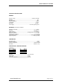
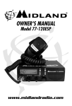
Owner’s Manual 77-120 ESP
Owner’s Manual 77-120ESP
http://www.midlandradio.com
www.midlandradio.com
Page 1 of 13
Owner’s Manual 77-120 ESP
Table of Contents
I.
II.
III.
IV.
V.
VI.
VII.
VIII.
IX.
X.
XI.
Introduction
How to install your Midland mobile CB
Check the requirements for your vehicle before you begin installation
Installation and operating accessories furnished with your Midland CB
Where to locate your CB transceiver
Mechanical Mounting
Power wiring (negative ground only)
Mounting the main unit
Installation of microphone hanger
Antenna
a. How to select, position install and tune the right one for you?
b. Where you locate your antenna does make a difference.
c. Antenna Installation
d. Tuning your antenna
Function & Location of Controls
a.
b.
c.
d.
e.
f.
g.
h.
i.
j.
k.
l.
m.
n.
o.
p.
q.
XII.
Front Panel Controls
Microphone Connector
ON/OFF Volume
MIC Gain
Squelch Control
RF Gain Control
Rotary Channel Selector
Channel Display
Frequency Display
TX Indicator
WX Indicator
ESP Indicator
S/RF Display
CB/WX
CH.9 Switch
ESP
FRQ
Back Panel
a. Antenna Connector
b. S-Meter Jack
c. EXT Speaker Jack
XIII.
How to operate your Transceiver for CB Use.
XIV.
How to operate your transceiver for weather receive
XV.
How ESP2 works
XVI.
Technical Data
XVII.
Warranty
www.midlandradio.com
Page 2 of 13
Owner’s Manual 77-120 ESP
Introduction Your 40 channel CB represents the state of the art in high tech engineering. This
unit is not only a full feature CB transceiver but incorporates a high performance
10 channel NOAA weather bureau VHF receiver. The full 10-channel weather
receiver allows use on all current and future NOAA weather bureau channels
plus Canadian and international channels. The unit incorporates microprocessor
controlled PLL circuitry for precise tuning and increased function. Receiver noise
and interference can now be largely eliminated by the new ESP2™ noise
reduction system. Also included is a backlighted Liquid Crystal Display (LCD)
digital information center that out-dates CB’s with LED readouts.
How to install your Midland mobile CB?
This transceiver may be installed in any 12 volt negative ground-system
car or truck. Almost all current U.S. and foreign vehicles use a negative system,
but some older models and some newer large trucks may have a positive
ground.
Check the requirements for your vehicle before you begin installation.
Generally, you have a negative-ground system if the minus ( - ) battery
terminal is connected to the motor block. Contact your dealer in the event you
are unable to determine your vehicle’s polarity system.
Installation and operating accessories furnished with your Midland CB:
1. Easy removal mounting bracket system.
2. Microphone bracket system.
3. All main-unit and microphone mounting hardware needed for normal
installation.
4. Plug-in microphone with coil cord.
5. FCC part 95, Subpart D.
6. Owner’s Manual.
Where to locate your CB transceiver.
Your new Midland CB is designed to be installed under the dash or
vertically on a console of your vehicle. Safety and convenience are the primary
considerations in deciding exactly where to locate your radio.
Caution: Be sure that the unit is located so that it does not interfere with the
driver or impair access to any controls. Connecting cables must be routed and
secured in such a manner as not to interfere with the operation of the brake,
accelerator or other controls. Interference from either the unit or connecting
cables may contribute to the loss of control of the vehicle.
www.midlandradio.com
Page 3 of 13
Owner’s Manual 77-120 ESP
Mechanical mounting
Note: Extreme care should be exercised when drilling into dash to avoid damage
to under-dash electronic ignition, cruise control, instrument and / or accessory
wiring. Your unit must be mounted so as not to interfere with air bag (SRS)
operation.
Step 1: Heeding the caution, use the mounting bracket as a template for marking
the location of screw holes under the dash. Use an awl, nail or other sharp
pointed object to mark the metal.
Step 2: Drill a 1/8” hole for each screw hole in the mounting bracket. Attach the
bracket to the dash with the 3/8” Phillips machine screws provided.
.
Step 3: Locate and secure the radio into the mounting bracket allowing working
space for later power connections.
Power wiring (negative ground only).
Step 1: If you have not determined whether your vehicle has a negative or
positive ground, do so now. Then disconnect the negative lead from the battery
to prevent short circuits that can occur during wiring.
Step 2: With negative ground, connect the red wire (the one with in-line fuse
holder) to either the ( a ) fuse block radio circuit (filtered), ( b ) cigarette lighter
(unfiltered for noise), or ( c ) directly to the positive post on your battery.
(Usually, the fuse block is the most convenient connecting point. It is also
possible to connect to the Accessory terminal on the fuse block, so that your CB
automatically goes off when the ignition goes off, preventing accidental battery
drainage.)
Note: In many new vehicles the only circuit that has noise filtering is the radio
circuit. Then tightly connect the black wire directly to the vehicle’s metal frame. A
good direct metal - to - metal ground is essential for optimum performance.
Installations using the cigarette lighter socket for power require an extra ground
wire from the radio chassis to the vehicle if the radio is not fastened to a
grounded part of the vehicle.
Step 3: Plug - in the power cord to the receptacle provided on the back of the
transceiver.
www.midlandradio.com
Page 4 of 13
Owner’s Manual 77-120 ESP
Mounting the main unit.
Step 1: Position the main unit between the bracket arms in line with the retention
knobs. Set the angle for optimum operating comfort and accessibility.
Step 2: Tighten the retention knobs.
Installation of microphone hanger.
Mounting holes are provided on the microphone hanger bracket. The bracket
can be attached to the vehicle dash, or other convenient location.
www.midlandradio.com
Page 5 of 13
Owner’s Manual 77-120 ESP
Antenna How to select, position install and tune the right one for you?
Basically, you have two types of mobile CB antennas - full-length whip and
loaded whip - and a variety of types of mounts (depending on where you locate
your antenna) to choose from.
Midland markets a broad line of high-performance antennas. The dealer who
sold you your Midland CB can advise which type is best for you.
Where you locate your antenna does make a difference.
Some general rules for antenna location that can aid CB performance:
1. Put your antenna mount as high on the vehicle as possible.
2. The higher the proportion of antenna length that is above the roof, the better.
3. If possible, mount the antenna in the center of whatever surface you choose.
4. Keep antenna cables away from noise sources, such as the ignition system,
gauges, electric fuel pumps, etc.
5. Make sure you have a solid metal-to-metal ground.
6. Exercise care to prevent cable damage.
Essentially, you have five location choices: the roof, gutter, rear deck, front cowl
or rear bumper. Where you decide to locate your antenna will determine the type
of antenna you install. Again consult your Midland CB dealer for advice and
guidance, and measure your needs against the attributes of the various Midland
antenna models he carries. Weather radio performance may be degraded by
use of a base loaded antenna.
Antenna installation.
Follow the manufacturer’s installation instructions carefully.
Warning: Never operate your CB radio without attaching an antenna or with a
broken antenna cable. This can result in damage to transmitter circuitry.
www.midlandradio.com
Page 6 of 13
Owner’s Manual 77-120 ESP
Tuning your antenna.
Some antennas are factory tuned. However, performance can usually be
improved by slightly lengthening or shortening its length, using a Standing Wave
Radio (SWR) meter. For the exact procedures to be used refer to the antenna
manufacturer’s installation manual.
You can buy an SWR meter separately or have your antenna checked by your
Midland CB Dealer’s service department or a two-way comm shop.
www.midlandradio.com
Page 7 of 13
Owner’s Manual 77-120 ESP
FUNCTION AND LOCATION OF CONTROLS
FRONT PANEL CONTROLS
1. MICROPHONE CONNECTOR: Plug in the supplied microphone to this
connector. The collar ring has a screw on locking ring. Push the ring onto
the units collar and screw on until it is tight.
2. ON/OFF VOLUME: In the off position your transceiver’s power is off. Turn
this control clockwise to switch on the unit and adjust the volume.
3. MIC GAIN: Rotating this control fully clockwise will result in
the greatest microphone output. /rotating the control counter-clockwise
reduces the microphone output, improving the sound in high noise
environments. This control can also be used to control optional power
microphone output.
4. SQUELCH CONTROL: Adjust this control until background noise just
disappears. If the control is adjusted too far clockwise it may cause
muting of weaker signals.
5. RF GAIN CONTROL: This control adjusts the receiver, sensitivity. Adjust
the control for best reception of distant or local stations. Begin with
control fully clockwise. To reduce reception of unwanted distant stations,
turn control counter-clockwise until only desired stations are heard.
www.midlandradio.com
Page 8 of 13
Owner’s Manual 77-120 ESP
6. ROTARY CHANNEL SELECTOR: This easy to operate control allows
changing of weather or CB channel, either up or down. This control will
not operate when emergency channel 9 has been selected by using the
“CH9” button or when the channel “LOCK” function has been activated.
7. CHANNEL DISPLAY: LCD (liquid crystal display) read-out of selected CB
or weather channel.
8. FREQUENCY DISPLAY. Displays channel frequency in MHz and kHz when the
“FRQ” switch is on.
9. TX INDICATOR: LCD indicator for showing the unit is transmitting.
10. WX INDICATOR: When this indicator is illuminated it indicates your unit
is in the weather receive mode. Weather channels are displayed.
11. ESP. INDICATOR: Indicates the ESP2™ “Noise Killer“ circuit has been
activated.
12. S/RF DISPLAY: LCD read-out of received signal strength and relative
transmitter power output.
13. CB/WX: This button causes your unit to change modes between NOAA
weather bureau receiver and CB operation.
14. CH.9 SWITCH: Press this for quick selection of emergency channel 9.
All other channels are locked out when channel 9 is activated by using
the “CH9” switch. Switch off “CH9” switch to return to normal CB
operation.
15. ESP: Pressing this button controls the ESP2™ audio system. Channel
noises are reduced and voices enhanced when ESP2™ is active.
16. FRQ: This switch selects Frequency in MHz display instead of channel
numbers.
BACK PANEL
ANTENNA CONNECTOR: Connect a standard 50-ohm CB antenna to this
connector.
S-METER JACK: A DC voltmeter may be connected to this jack for
precision monitoring of received signal strength.
www.midlandradio.com
Page 9 of 13
Owner’s Manual 77-120 ESP
EXT SPEAKER JACK: When a speaker is connected to this jack the
internal speaker is by-passed. All received signals will be heard through
the external speaker when it is connected. The speaker connected to the
“EXT” jack should be rated at 8 ohms and 5 watts or more.
HOW TO OPERATE YOUR TRANSCEIVER FOR CB USE
You should become familiar with the controls and complete the preceding
installation instructions before attempting operation of your CB.
1. Adjust the squelch control fully counter-clockwise
2. Rotate the on/off volume control clockwise to turn the unit on. Adjust the
volume for a normal listening level.
3. Select the desired channel by the rotary channel selector. Rotate the squelch
control until the background noise is just quieted. You are now in the receive
mode.
NOTE: If the channel will not change, check that the “CH9 switch is not on. In
this case switch the “CH9” switch off to deactivate this function
4. To transmit press the PTT bar on the side of the microphone. Hold the
microphone 2 to 3 inches from your lips and speak in a normal voice.
5. To receive simply release the PTT bar.
TO OPERATE YOUR TRANSCEIVER FOR WEATHER RECEIVE
1. Follow steps 1 and 2 above.
2. Press the “WX” button.
3. Using the rotary channel selector select the active channel in your area.
www.midlandradio.com
Page 10 of 13
Owner’s Manual 77-120 ESP
How ESP2™ works to make your CB sound better.
The ESP2™ noise reduction system constantly monitors the signal strength and
the type of noise present. When the signal strength is too low for good reception,
the receiver sound is automatically adjusted to dramatically reduce the noise that
comes through the speaker. While the noise is decreased the actual sounds you
need to hear are increased.
Skip interference can cause whistles and howling sounds. Electrical interference from power
lines, ignition systems or other sources can produce low humming and buzzing noise. These
high and low sounds are not needed for communications. ESP2™ can determine the difference
between undesired noises and sounds you want to hear and filter the noises out.
These results ESP2™ can accomplish without decreasing receiver range (it
usually increases range). Most importantly, ESP2™ works by itself and does not
need to be listening to other ESP2™ equipped CB’s to be 100% effective.
The end result of ESP™ is that you can lower or completely stop using your
squelch control. You will hear weak signals that cause other CB’s to hear only
noise. With this new patented sound control system you will find yourself using
your CB more thereby increasing your safety and enjoyment.
www.midlandradio.com
Page 11 of 13
Owner’s Manual 77-120 ESP
TECHNICAL SPECIFICATIONS
GENERAL
Frequency range ..........................................................................26.965-27.405 MHz
Channels ..............................................................................................................40
Modulation type ...................................................................................................AM
Antenna impedance .......................................................................................50 Ohm
Loudspeaker ...................................................................................................8 Ohm
Microphone ..................................................................................................Electret
Power Supply ....................................................................13.8 VDC negative ground
RECEIVER ( CB, 26.965-27.405 MHz )
Sensitivity at 10db S/N......................................................................................0.6 uV
Selectivity .............................................................................................6 db @ 5 Khz
Squelch range ......................................................................................0.5 uV-500 uV
Audio output power ..................................................3.0 W @ 8 Ohm ( 10% distortion)
Distortion at 1000 mV ............................................................................................3%
Audio frequency response ........................................................................400-2400 Hz
Intermediate frequency .......................................................I ° 10.695 MHz II ° 455 Khz
Spurious response ................................................................ .............more than 45 db
TRANSMITTER
RF Output Power ................................................................................................4.0 W
Frequency Tolerance .........................................................................................0.005%
Harmonic Suppression ..........................................................................More than 60 db
Modulation ...........................................................................................AM 90% ( ± 5%)
SPECIFICATION - WEATHER RECEIVER
CHANNELS
00
163.275
01
162.550
02
162.400
03
162.475
04
162.425
05
06
07
08
09
162.450
162.500
162.525
161.650
161.775
Sensitivity _________________________________1.0 uV for 20 db
Audio Power _______________________________3.0 W
Audio Load ________________________________8 ohms
Intermediate Frequency ______________________455 Khz
www.midlandradio.com
Page 12 of 13
Owner’s Manual 77-120 ESP
LIMITED WARRANTY.
Midland Consumer Radio will repair or replace, at its option without charge, any Midland Mobile, Base Station, or full
power Hand-Held Citizens Band transceiver which fails due to a defect in material or workmanship within one year
following the initial consumer purchase.
This warranty does not include any carrying cases, earphones, or telescoping antennas which may be a part of or
included with the warranted product, or the cost of labor for removal or re-installation of the product in a vehicle or other
mounting.
Performance of any obligation under this warranty may be obtained by returning the warranted product, freight prepaid,
along with proof of purchase date, to Midland Consumer Radio, Warranty Service Department 1670 North Topping,
Kansas City, Missouri 64120, or to any “ Midland Authorized Warranty Service Station,” or to the place of purchase ( if a
participating dealer).
Warranty information and the location of the nearest “Midland Authorized Warranty Service Station,” may be obtained by
writing Midland Consumer Radio, Warranty Service Department.
This warranty gives you specific legal rights, and you may also have other rights which vary from state to state.
Note: The above warranty applies only to merchandise purchased in the United States of America or any of the
territories or possessions or from U.S. military exchange. For warranty coverage on merchandise purchased elsewhere,
consult the supplemental warranty information included with this product or ask your dealer.
SERVICE
If it ever becomes necessary to return your unit for service:
Pack the unit in its original box and packing, Improper packing may result in damage during shipment. Include $7.50 for
return postage and handling. (Note: Some states do not require you to pay for postage and handling).
Include a full description of any problems. Include your telephone number.
You do not need to return accessory items (brackets, screws, power cord, antenna, etc.) unless they may be directly
related to the problem.
Include a photocopy of the bill of sale or other proof of purchase showing the date of sale. This information must be
included before warranty service can be considered.
A flat rate of $45.00 will apply to repairs not covered by warranty. Send only cashiers check, money order or Master Card
or Visa card number.
MIDLAND RADIO CORPORATION
1120 Clay Street
North Kansas City, MO 64116
Phone 816-241-8500. Fax 816-241-5713
E-mail: [email protected]
Or visit us at www.midlandradio.com
FCC Compliance Information
Midland Citizens Band Transceiver
Model 77-120ESP
This device complies with part 15 of the FCC Rules. Operation is subject to the following two
conditions:
(1) This device may not cause harmful interference
(2) This device must accept any interference received including interference that may cause
undesired operation.
For compliance information contact: Midland Radio Corporation
www.midlandradio.com
Page 13 of 13